determining the permeability of soil at unversiti malaysia paihang ...
9. SOIL PERMEABILITY
9.0 Why is it important to determine soil permeability?
The dikes of the pond should be built with soil which will ensure a good water retention. Again, soil quality will have to
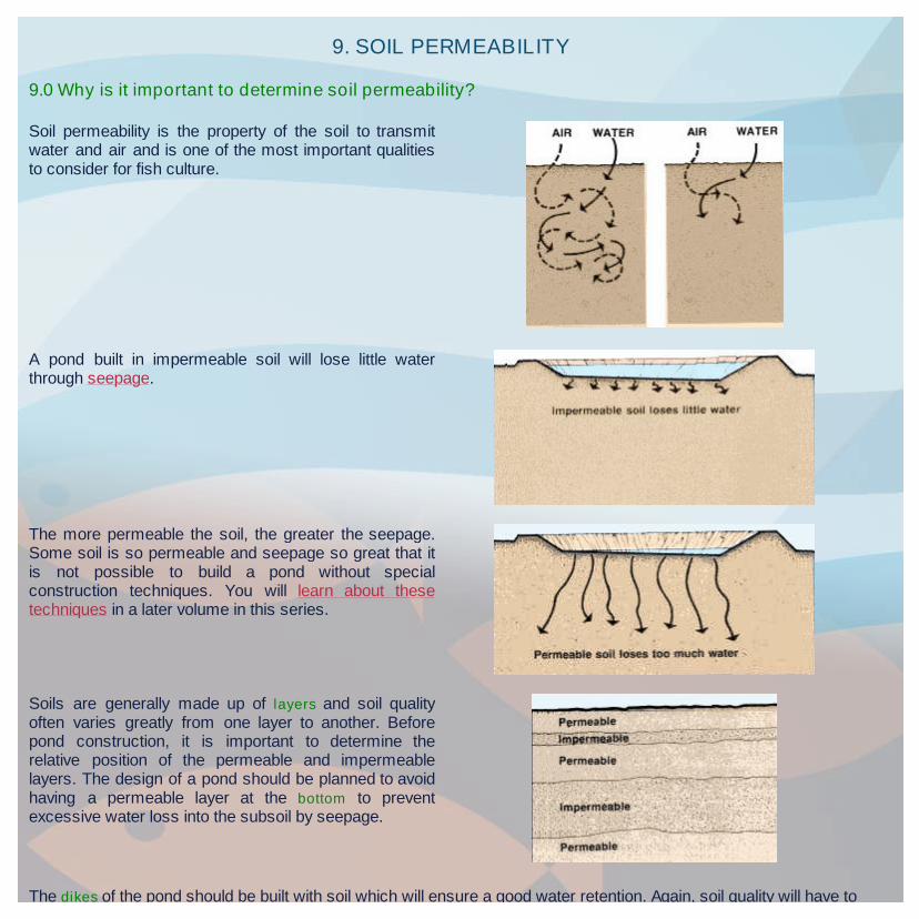
Soil permeability is the property of the soil to transmitwater and air and is one of the most important qualitiesto consider for fish culture.
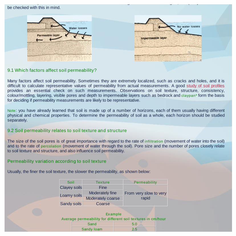
A pond built in impermeable soil will lose little waterthrough seepage.
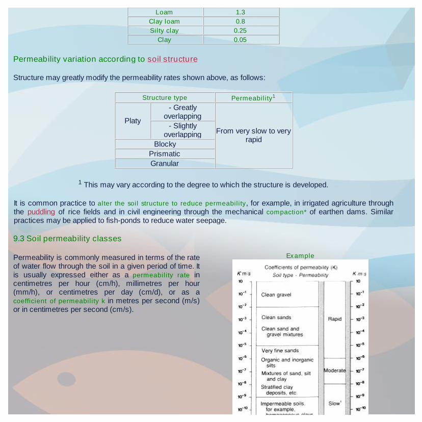
The more permeable the soil, the greater the seepage.Some soil is so permeable and seepage so great that itis not possible to build a pond without specialconstruction techniques. You will learn about thesetechniques in a later volume in this series.
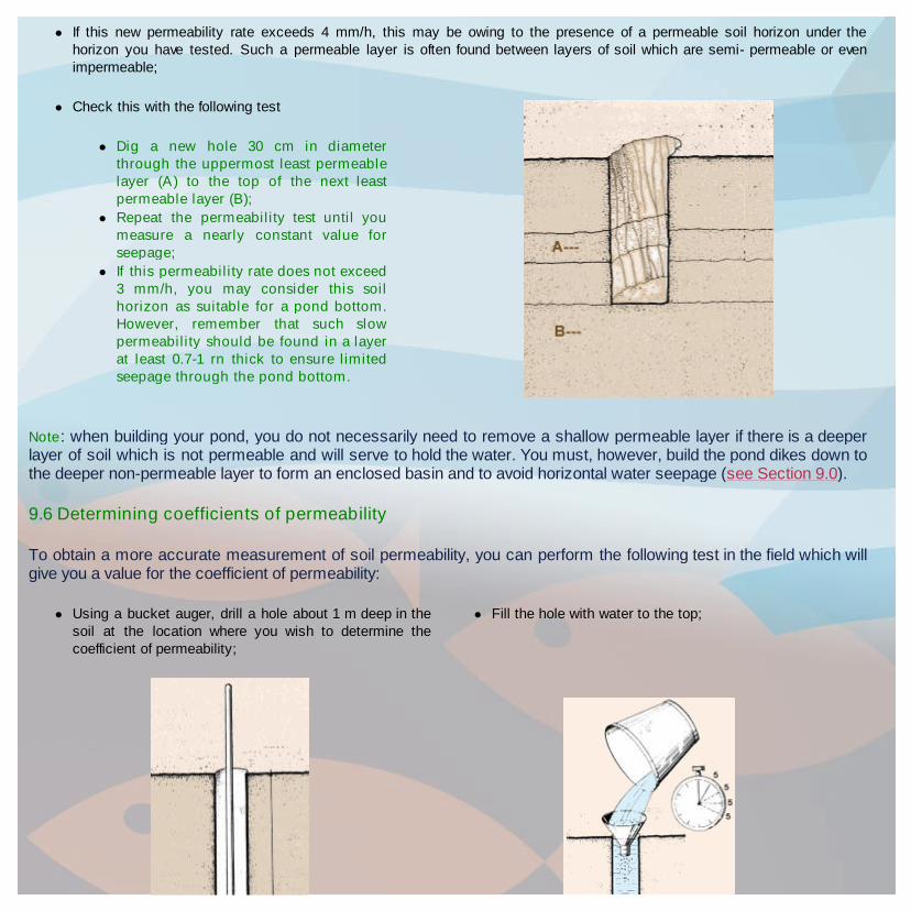
Soils are generally made up of layers and soil qualityoften varies greatly from one layer to another. Beforepond construction, it is important to determine therelative position of the permeable and impermeablelayers. The design of a pond should be planned to avoidhaving a permeable layer at the bottom to preventexcessive water loss into the subsoil by seepage.
The dikes of the pond should be built with soil which will ensure a good water retention. Again, soil quality will have tobe checked with this in mind.
9.1 Which factors affect soil permeability?
Many factors affect soil permeability. Sometimes they are extremely localized, such as cracks and holes, and it isdifficult to calculate representative values of permeability from actual measurements. A good study of soil profilesprovides an essential check on such measurements. Observations on soil texture, structure, consistency,colour/mottling, layering, visible pores and depth to impermeable layers such as bedrock and claypan* form the basisfor deciding if permeability measurements are likely to be representative.
Note: you have already learned that soil is made up of a number of horizons, each of them usually having differentphysical and chemical properties. To determine the permeability of soil as a whole, each horizon should be studiedseparately.
9.2 Soil permeability relates to soil texture and structure
The size of the soil pores is of great importance with regard to the rate of infiltration (movement of water into the soil)and to the rate of percolation (movement of water through the soil). Pore size and the number of pores closely relateto soil texture and structure, and also influence soil permeability.
Permeability variation according to soil texture
Usually, the finer the soil texture, the slower the permeability, as shown below:
Soil Texture Permeability
Clayey soils Fine
From very slow to veryrapid
Loamy soilsModerately fine
Moderately coarse
Sandy soils Coarse
Example
Average permeability for different soil textures in cm/hour
Sand 5.0
Sandy loam 2.5
Permeability variation according to soil structure
Structure may greatly modify the permeability rates shown above, as follows:
Loam 1.3
Clay loam 0.8
Silty clay 0.25
Clay 0.05
1 This may vary according to the degree to which the structure is developed.
It is common practice to alter the soil structure to reduce permeability, for example, in irrigated agriculture throughthe puddling of rice fields and in civil engineering through the mechanical compaction* of earthen dams. Similarpractices may be applied to fish-ponds to reduce water seepage.
Structure type Permeability1
Platy
- Greatlyoverlapping
From very slow to veryrapid
- Slightlyoverlapping
Blocky
Prismatic
Granular
9.3 Soil permeability classes
Permeability is commonly measured in terms of the rateof water flow through the soil in a given period of time. Itis usually expressed either as a permeability rate incentimetres per hour (cm/h), millimetres per hour(mm/h), or centimetres per day (cm/d), or as acoefficient of permeability k in metres per second (m/s)or in centimetres per second (cm/s).
Example

For agriculture and conservation uses, soil permeability classes are based on permeability rates, and for civil
engineering, soil permeability classes are based on the coefficient of permeability (see Tables 15 and 16).
For fish culture, two methods are generally used to determine soil permeability. They are:
The coefficient of permeability;
The seepage rate.
For the siting of ponds and the construction of dikes, the coefficient of permeability is generally used to qualify thesuitability of a particular soil horizon:
Dikes without any impermeable clay core may be built from soils having a coefficient of permeability less than
K = 1 x 10⁻⁴ m/s;
Pond bottoms may be built into soils having a coefficient of permeability less than K = 5 x 10⁻⁶ m/s.
For pond management, the seepage rate is generally used:
In commercial pond culture, an average seepage rate of 1 to 2 cm/d is considered acceptable, but corrective measuresshould be taken to reduce soil permeability when higher values exist, particularly when they reach 10 cm/d or more.
9.4 Measurement of soil permeability in the laboratory
When you take an undisturbed sample to a testing laboratory, to measure permeability, a column of soil is placedunder specific conditions such as water saturation and constant head of water. The result will be given to you either asa permeability rate (see Table 15), or as a coefficient of permeability (see Table 16).
TABLE 15
Soil permeability classes for agriculture and conservation
Soil permeabilityclasses
Permeability rates1
cm/hour cm/day
Very slowLess than
0.13Less than 3
Slow 0.13 - 0.3 3 - 12
Moderately slow 0.5 - 2.0 12 - 48
Moderate 2.0 - 6.3 48 - 151
Moderately rapid 6.3 - 12.7 151 - 305
Rapid 12.7 - 25 305 - 600
Very rapid More than 25 More than 600
TABLE 16
Soil permeability classes for civil engineering
Soil permeabilityclasses
Coefficient ofpermeability (K in m/s)
Lower limit Upper limit
Permeable 2 x 10⁻⁷ 2 x 10⁻¹
Semi-permeable 1 x 10-11 1 x 10⁻⁵
Impermeable 1 x 10-11 5 x 10⁻⁷

9.5 Measurement of soil permeability in the field
To measure soil permeability in the field, you can use one of the following tests:
The visual evaluation of the permeability rate of soil horizons;
A simple field test for estimating soil permeability;
A more precise field test measuring permeability rates.
The visual evaluation of the permeability rate of soil horizons
The permeability of individual soil horizons may be evaluated by the visual study of particular soil characteristics whichhave been shown by soil scientists to be closely related to permeability classes. The most significant factor inevaluating permeability is structure: its type, grade, and aggregation characteristics, such as the relationship betweenthe length of horizontal and vertical axes of the aggregates and the direction and amount of overlap.
Although neither soil texture nor colour mottling alone are reliable clues, these soil properties may help to estimatepermeability when considered together with the structural characteristics. To evaluate visually the permeability of soilhorizons:
Examine a fresh soil profile in an open pit;
Determine the soil horizons present;
Using Table 17A, evaluate the permeability class to which each horizon belongs, carefully studying the structuralcharacteristics of the soil;
Confirm your results through the other soil properties shown in Table 17B;
Ranges of permeability rates may then be found in Table 15.
1 Saturated samples under a constant water head of 1.27
cm
TABLE 17AVisual indicators of permeability: structural characteristics of soil

A simple field test for estimating soil permeability
TABLE 17 BVisual Indicators of permeability: texture, physical behaviour and colour of soil

Dig a hole as deep as your waist; Early in the morning, fill it with water to the top;
By the evening, some of the water will have sunk into thesoil;
Fill the hole with water to the top again, and cover it withboards or leafy branches;
If most of the water is still in the hole the next morning,the soil permeability is suitable to build a fish-pond here;

A more precise field test for measuring permeability rates
Repeat this test in several other locations as manytimes as necessary, according to the soil quality.
Carefully examine the drawings you have made whenstudying your soil profiles;
Note: you could also use the visual method (see Tables
17A and 17B) to estimate permeability.
On the basis of texture and structure, determine whichsoil horizons seem to have the slowest permeability;
Mark the soil horizons on your drawings which seem tohave the slowest permeability. Use a coloured pencil;
Note: water seeps into the soil both horizontally andvertically, but you need only be concerned with thevertical water seepage because this is mainly whathappens in ponds.
Dig a hole approximately 30 cm in diameter until youreach the uppermost least permeable horizon;
Thoroughly smear the sides of the hole with heavy wetclay or line them with a plastic sheet, if available, tomake them waterproof;
Pour water into the hole to a level of about 10 cm;

At first, the water will seep down rather quickly, and you will have to refill as it disappears. When the pores of the soil are fullof water, seepage will slow down. You are then ready to measure the permeability of the soil horizon at the bottom of thehole;
Make sure that the water in the hole is about 10 cmdeep as before. If it is not, add water to reach that level;
Put a measuring stick into the water and record theexact water depth, in millimetres (mm);
Check the water level in the hole every hour for severalhours. Record the rate of seepage for each hourlyperiod. If the water disappears too rapidly, add water tobring the level up to 10 cm again. Measure the waterdepth very carefully;

If the permeability rate is faster than 5 mm/h, this may be owing to a strongly developed structure in the soil. In suchcases, you try to reduce the permeability rate by destroying the structure, as follows:
If this new permeability rate does not exceed 4 mm/h, you may consider this soil horizon as suitable for a pond bottom.However, the entire bottom of the pond will have to be puddled before filling it with water;
When your hourly measurements become nearly thesame, the rate of permeability is constant and you maystop measuring;
If there are great differences in seepage each hour,continue pouring water into the hole to keep the level at10 cm until the rate of seepage remains nearly thesame;
Note: a soil horizon with suitable permeability for a pondbottom should also be at least 0.7-1 m thick, unlesslower horizons exist with suitable permeability andthickness.
Now compare your results with the following values:
Permeability rate inmm/h
Suitability of horizon for a pond bottom
Slower than 2 Acceptable seepage: soil suitable
2-5Fast seepage: soil suitable ONLY if seepage due to soil structure which will disappearwhen pond is filled
5-20Excessive seepage: soil unsuitable unless seepage can be reduced as describedbelow
Puddle the bottom soil of the hole as deep as you can; Repeat the more precise permeability test until you canmeasure a nearly constant value for seepage.
If this new permeability rate exceeds 4 mm/h, this may be owing to the presence of a permeable soil horizon under thehorizon you have tested. Such a permeable layer is often found between layers of soil which are semi- permeable or evenimpermeable;
Note: when building your pond, you do not necessarily need to remove a shallow permeable layer if there is a deeperlayer of soil which is not permeable and will serve to hold the water. You must, however, build the pond dikes down tothe deeper non-permeable layer to form an enclosed basin and to avoid horizontal water seepage (see Section 9.0).
9.6 Determining coefficients of permeability
To obtain a more accurate measurement of soil permeability, you can perform the following test in the field which willgive you a value for the coefficient of permeability:
Check this with the following test
Dig a new hole 30 cm in diameterthrough the uppermost least permeablelayer (A) to the top of the next leastpermeable layer (B);
Repeat the permeability test until youmeasure a nearly constant value forseepage;
If this permeability rate does not exceed3 mm/h, you may consider this soilhorizon as suitable for a pond bottom.However, remember that such slowpermeability should be found in a layerat least 0.7-1 rn thick to ensure limitedseepage through the pond bottom.
Using a bucket auger, drill a hole about 1 m deep in thesoil at the location where you wish to determine thecoefficient of permeability;
Fill the hole with water to the top;
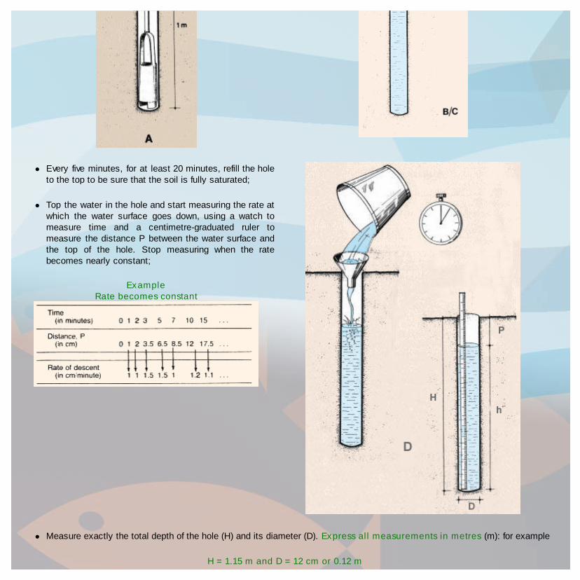
Measure exactly the total depth of the hole (H) and its diameter (D). Express all measurements in metres (m): for example
H = 1.15 m and D = 12 cm or 0.12 m
Every five minutes, for at least 20 minutes, refill the holeto the top to be sure that the soil is fully saturated;
Top the water in the hole and start measuring the rate atwhich the water surface goes down, using a watch tomeasure time and a centimetre-graduated ruler tomeasure the distance P between the water surface andthe top of the hole. Stop measuring when the ratebecomes nearly constant;
ExampleRate becomes constant

For each of the above two consecutive measurements of time/distance, calculate the coefficient of permeability K usingthe following formula:
K= (D÷2) x In (h1÷ h2) / 2 (t2- t1)
where (D ÷ 2) is the radius of the hole or half its diameter in metres; In refers to the Napierian or natural logarithm;
h1 and h2 are the two consecutive depths of water in metres, h1 at the start and h2 at the end of the time interval;
(t2 - t1 ) expresses the time interval between two consecutive measurements, in seconds;
Note: the h-values may be readily calculated as the differences between the total depth of the hole H and thesuccessive P values. Be careful to express all the measurements in metres and seconds so as to obtain K in m/s.
Now compare your K values (in m/s) with those in Table 16.
Example
If (D ÷ 2) = 0.12 m ÷ 2 = 0.06 m and H = 1.15 m, calculations of the various K values are made progressively according to theformula (see Table 18).
Note: for obtaining the natural logarithm of (h1 ÷ h2), you will have to use either a logarithmic table or a pocket
calculator.
Remember that 10 - 6 = 0.000001 and 6.8 x 10-6 = 0.0000068, the negative exponent of 10 reflecting the decimal placeto be given to the multiplicant.
If you wish to compare a K value (m/s) with permeability rates (cm/day), multiply K by 8 640 000 or 864 x 104 such asfor example:
K = 1 x 10⁻⁵ m/s = 86.4 cm/day
TABLE 18Successive steps for the calculation of coefficients of permeability on the basis of field measurements
(for a test hole with H = 1.15 m and D = 0.12 m)
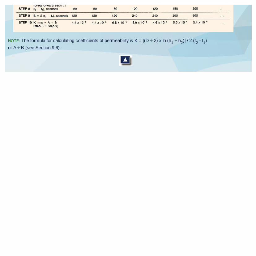
NOTE: The formula for calculating coefficients of permeability is K = [(D ÷ 2) x In (h1
÷ h2)] / 2 (t
2- t
1)
or A ÷ B (see Section 9.6).