9. Dynamic stability of industrial networks
36
747 Publication, traduction et reproduction totales ou partielles de ce document sont rigoureusement interdites sauf autorisation écrite de nos services. The publication, translation and reproduction, either wholly or partly, of this document are not allowed without our written consent. Industrial electrical network design guide T & D 6 883 427/AE 9. Dynamic stability of industrial networks
Transcript of 9. Dynamic stability of industrial networks

747
Publication, traduction et reproduction totales ou partielles de ce document sont rigoureusement interdites sauf autorisation écrite de nos services.The publication, translation and reproduction, either wholly or partly, of this document are not allowed without our written consent.
Industrial electrical network design guide T & D 6 883 427/AE
9. Dynamic stability of industrialnetworks

748
Publication, traduction et reproduction totales ou partielles de ce document sont rigoureusement interdites sauf autorisation écrite de nos services.The publication, translation and reproduction, either wholly or partly, of this document are not allowed without our written consent.
Industrial electrical network design guide T & D 6 883 427/AE
9. DYNAMIC STABILITY OF INDUSTRIAL NETWORKS
Because electrical energy is difficult to store, there must be a continuous balance betweenproduction and consumption. Indeed, the only stored energies in an electrical network are thekinetic energy of rotating machines and the energy of capacitors: these have storagecapacities of several seconds.
The generators, loads and electrical networks that connect them up have mechanical andelectrical inertias which make it difficult to maintain a balance guaranteeing relatively constantfrequency and voltage.
Normally, when confronted with a power variation, the electrical system recovers its stabilityafter several oscillations.
In some cases, the oscillating operating conditions may diverge. It is necessary to carry outstudies to determine the means to be implemented in order to avoid this phenomenon andguarantee stability of the electrical network.
Studies are especially necessary in the case of industrial networks which have one or moregenerator sets and motors.
This chapter will allow us to understand why instability may occur, what are the most frequentcauses and what are the induced effects. It gives the precautions to be taken, shows how astudy is carried out and provides an example.
n network stability
This is characterised by variations in the active and reactive powers which flow through thenetwork and is measured by variations in time of voltages, currents and frequenciesassociated with these powers.
Several definitions characterise network stability:
o steady-state stability
The network has a stable behaviour; this means that when it is subject to small disturbances, itreturns to its initial operating point with possible damped oscillations up to the return to abalanced state.
o transient-state stability
When there is a change from a static stable state to a different state, following a lengthydisturbance, whether intentional or not, this change in balance is accompanied by a dampedoscillating variable state considered as being acceptable with respect to pre-defined voltage,frequency and duration intervals ( ∆ ∆U f, , duration → below a maximum value).
749
Publication, traduction et reproduction totales ou partielles de ce document sont rigoureusement interdites sauf autorisation écrite de nos services.The publication, translation and reproduction, either wholly or partly, of this document are not allowed without our written consent.
Industrial electrical network design guide T & D 6 883 427/AE
o transient-state instability
This can be seen when, following a considerable disturbance, the oscillating state is divergent.It induces a loss of power supply.
o dynamic-state stability
The network is capable of avoiding any divergent oscillating state and returning to anacceptable stable state. This includes possible intervention of the protections and automaticdevices.
Dynamic stability studies consist in:
- imagining the main critical scenarios such as a short circuit, loss of generator sets, loss ofutility power supply, considerable load variation, etc.
- predicting the behaviour of the network when faced with these disturbances
- deciding on the means to be implemented such as types of protection and settings, loadshedding/restoration, forbidden configurations, etc., which allow instability to be avoided
These studies thus allow us to understand the behaviour of the network and determine themeans of reducing the risks of loss of power supply.

750
Publication, traduction et reproduction totales ou partielles de ce document sont rigoureusement interdites sauf autorisation écrite de nos services.The publication, translation and reproduction, either wholly or partly, of this document are not allowed without our written consent.
Industrial electrical network design guide T & D 6 883 427/AE
9.1. Behaviour of an industrial electrical network
The behaviour of an electrical network on occurrence of transient phenomena depends on thebehaviour of each of its elements. Starting from a stable state, these elements will influencethe transient behaviour of the entire network. At the end of disturbance, they will either be inthe same stable state as before, or in a different stable state, or in an unstable state, whichgenerally leads to the loss of one or several elements through the activation of protections. It isimportant, therefore, to know the behaviour of each element in order to determine thebehaviour of the entire electrical network.
n passive loads
These are loads such as lighting, heating, capacitors, etc. having the following electricalvariation laws:
PV
VP
nn=
⋅
2
(heating, lighting, etc.)
QV
VQ
nn=
⋅
2
(capacitors)
n power electronic assemblies
More and more loads of this type are to be found in industrial networks (see § 3.4.7).
They are generally highly sensitive to voltage variations. For example, a varying speed motorcan be de-energized by a protection for a voltage variation of roughly - 15 %.
n transformers and cables
Transformers and cables which ensure the flow of electrical energy between sources andloads are characterised by their impedances. These create voltage drops and Joule losseswhich depend on the current flowing through them.
The values of these impedances are very influential in transient operating conditions:
- high inrush currents cause voltage drops which may be critical- high reactances between sources may induce long duration oscillations.

751
Publication, traduction et reproduction totales ou partielles de ce document sont rigoureusement interdites sauf autorisation écrite de nos services.The publication, translation and reproduction, either wholly or partly, of this document are not allowed without our written consent.
Industrial electrical network design guide T & D 6 883 427/AE
n asynchronous machines
Owing to their behaviour and their majority presence in industrial networks (up to 80 % ofconsumed power in some installations), asynchronous motors play a preponderant role instability phenomena.
o influence of voltage dips
Figure 9-1 shows torque curves in relation to the speed of a double cage asynchronous motorfeeding a pump (see § 3.3.1).
B
A
N
N s
0.1 0.5 0.6 0.8 1
1
0.8
0.2load torque
O
torque at Vn
torque at 0.7 Vn
T
T n
N
Ns: speed in relation to motor synchronism speed
T
Tn: torque in relation to motor nominal torque
Figure 9-1: torque curves in relation to the speed of a double cage asynchronous motor feeding a pump
The operating point ( O ) is located at the intersection of the motor torque and load torquecurves. The motor torque is proportional to the square of the voltage (see § 3.3.1 andfig. 3-15).
Motor stability depends on the relative positions of the motor torque and load torque curves. Ifthe motor suffers an interruption or a high voltage dip, it will slow down and operate at areduced speed, e.g. 60% of the synchronism speed. The reduction in speed is all the greaterthe smaller the inertia. Its ability to reaccelerate and return to its original stable state dependson the voltage value when it is recovered.
752
Publication, traduction et reproduction totales ou partielles de ce document sont rigoureusement interdites sauf autorisation écrite de nos services.The publication, translation and reproduction, either wholly or partly, of this document are not allowed without our written consent.
Industrial electrical network design guide T & D 6 883 427/AE
Let us assume that, owing to the current inrushes in the network, the voltage is equal to 0 7. Vn
at that moment. The motor torque is only just above the load torque (point B in relation to pointA, see fig. 9-1). The motor will "creep" (accelerate very slowly), and be disconnected from thenetwork through the activation of excessive start-up time, rotor locking or undervoltageprotections (see § 7.9 and 7.12 of the Protection guide).
Figure 3-14 shows that once the motor has slowed down a little, it absorbs a high current. Thiscurrent causes voltage drops which makes reacceleration all the more difficult. If all the motorsof an industrial installation slow down (e.g. after a high voltage dip in the public distributionnetwork), the current absorbed by all the motors on reacceleration creates voltage drops whichmay make reacceleration impossible. The solution is often to use an automatic fast-actingload-shedding and progressive load restoration device. Stability may thus be improved byreducing current inrushes and hence voltage drops.
To sum up, asynchronous motors are important elements in dynamic stability; they mayencounter operating difficulties following the sudden passage of a reduced voltage supply.
o influence of undervoltages
The absence of supply voltage does not immediately eliminate voltage at the motor terminals.Indeed, the flux stored in the motor cannot be extinguished instantaneously. The rotating fieldcreated by the rotor then induces a "remanent" voltage in the stator the amplitude of whichdecreases exponentially (time constant equal to several tenths of a second). The frequency ofthis voltage decreases with the rotation speed. If, when voltage reappears on the network, it isin phase opposition with a remanent voltage having an amplitude which has decreased verylittle, a high overcurrent is then generated which may reach twice the motor starting peak, i.e.12 to 15 times its nominal current.
This may have considerable consequences on the motor:
- additional heating and electrodynamic stress in the windings possibly causing insulationbreakdowns
- torque jolt possibly leading to unacceptable mechanical stress (especially on couplings).
The means of providing against this risk is to install a remanent undervoltage protection whichforbids supply restoration if the remanent voltage is above a threshold generally set at a valueclose to 20% of Vn (see § 7.13. of the Protection guide).

753
Publication, traduction et reproduction totales ou partielles de ce document sont rigoureusement interdites sauf autorisation écrite de nos services.The publication, translation and reproduction, either wholly or partly, of this document are not allowed without our written consent.
Industrial electrical network design guide T & D 6 883 427/AE
n synchronous machines
These play a predominant role in network stability phenomena.
Paragraph 4.2 explains the operation of synchronous machines and their steady-state stability.
The following are the main equations which govern their operation:
E V X Id= +
PEV
Xd=
3sin δ
E : internal electromotive force (e.m.f.); its value varies proportionally to the direct current that flows through the
rotor (without saturation)
V : voltage at the machine terminals
Xd : synchronous reactance
I : current circulating at the machine terminals
P : machine active power
δ : angular variation equal to the phase angle of E in relation to V or the mechanical angle between the rotor
shaft E and the synchronous reference made up of the voltage V at the machine terminals
The fundamental rule of generator steady-state stability, i.e. its ability to meet a slow loadvariation, should be pointed out here: operation is only stable if the angular variation δremains below 90 °.

754
Publication, traduction et reproduction totales ou partielles de ce document sont rigoureusement interdites sauf autorisation écrite de nos services.The publication, translation and reproduction, either wholly or partly, of this document are not allowed without our written consent.
Industrial electrical network design guide T & D 6 883 427/AE
o dynamic stability of synchronous machines connected to an infinite power network
Dynamic stability problems come from the machine changing from a stable state to a differentstate. Let us consider the case of a machine connected to a public distribution network whichis subject to a surge of mechanical power supplied by the turbine. The turbine suddenly goesfrom a supplied power P1 to a supplied power P2 (see fig. 9-2).
A
B CD
E
P
90°
P2
1 2 3
P1
Figure 9-2: displacement of the generator operating point following an increase in mechanical power
The slow increase in power from P1 to P2 would slowly cause a displacement from point A
to point C while remaining on the curve. But the sudden application of this power increasedoes not directly lead to point C. It is indeed impossible, taking into account the mechanicalinertias, to suddenly go from an angular variation δ1 to an angular variation of δ 2 . Thus the
machine instantaneously goes from point A to point B, then the angle δ increases from δ1
to δ 2 . But on arriving at point C stabilisation is not immediate. The mechanical inertia of the
machine brings its operating point up to D . From here, deceleration down to point C is finallystabilised, possibly after several oscillations.
The calculations carried out using the mechanical and electrical energies of the machine showthat the position of point E is defined by the law of areas; areas ABC and CDE are equal.Indeed, we can show that area ABC is proportional to the mechanical energy stored when themachine moves from point B to point C and area CDE when it moves from point D topoint C .
Consequently, the maximum angular variation δ max may be above 90 ° for a transient period.
The dynamic stability limit is thus higher than the static stability.

755
Publication, traduction et reproduction totales ou partielles de ce document sont rigoureusement interdites sauf autorisation écrite de nos services.The publication, translation and reproduction, either wholly or partly, of this document are not allowed without our written consent.
Industrial electrical network design guide T & D 6 883 427/AE
Nevertheless, it is possible that the difference between P1 and P2 is so great that there is no
point D allowing the law of areas to be complied with (see fig. 9-3). The generatoraccelerates from point B to point C , then up to point X . At this point, it continues toaccelerate remaining on the curve and the power transmitted to the network decreasesbecoming negative (motor operation). The angle δ continuously increases and there is a lossof synchronism through overspeed.
A
B C
P
90°
P1
P2
1 2
X
180°
Figure 9-3: instability following a sudden increase in mechanical power
Following a similar logic, we can arrive at the following two conclusions:
- the risks of loss of dynamic stability are related to sudden and considerable changes innetwork state, mechanical power or exciting current supplied to the generators
- the risks of loss of dynamic stability are all the greater the closer the power supplied by themachine is to the static stability limit.
The notion of steady-state stability is evaluated through the expression of the synchronizing torque:
TT P EV
Xsel
d= =
∂∂ δ ω
δ3
cos (see § 4.2.1.1 - Static stability)
Tel : electromagnetic load torque
Indeed, when δ is low, cosδ is high, as well as ∂∂ δTel ; in this case, a small variation of δ
causes a large torque variation and thus an energetic return to the balanced state. Reciprocally,
when δ is close to π2
, a variation of δ causes a small torque variation and thus a much less
energetic return to the balanced state. Thus, a high value of Ts (lowδ ) encourages stability and
thus maintenance of synchronism. On the other hand, a low value of Ts (δ close to π2
) renders
the machine unstable when δ varies which causes loss of synchronism.

756
Publication, traduction et reproduction totales ou partielles de ce document sont rigoureusement interdites sauf autorisation écrite de nos services.The publication, translation and reproduction, either wholly or partly, of this document are not allowed without our written consent.
Industrial electrical network design guide T & D 6 883 427/AE
In practice, industrial generators are generally made up so that the angular variation is almostequal to 70° for the nominal active power and zero reactive power, so that a margin of stabilityis kept in the event of a transient disturbance. However, if the generator absorbs reactivepower, δ comes close to 90 ° and the risk of instability is greater on occurrence of adisturbance.
Furthermore, generator speed and voltage regulators play an essential role in the improvementof network stability when disturbances occur.
n regulations
The purpose of regulations is to allow correct operation during variations of load or drivingpower:
- voltage and frequency stability for an independent network
- active and reactive power stability of generators when they are connected to a publicdistribution network
Let us take the simple case of a generator, the only voltage supply source of an independentnetwork, which is fitted with a speed regulator.
The network frequency, proportional to the generator rotation speed, is set by the primaryspeed regulation of the mechanical drive; the mechanical power is adapted to the power to besupplied so that the required frequency is maintained. Thus, automatic regulation is defined byits droop which expresses the frequency variation in relation to the power (see fig. 9-4).
P
f
f0
f0 2%
f0 2%
P 0 Pn
2Pn
P P
f f
n
0
droop lineat P = 0
(secondary regulation)
primary regulationdroop line
droop line at(secondary regulation)
P Pn
action of secondary regulation
B
A
Figure 9-4: generator droop line (primary regulation) and action of secondary regulation

757
Publication, traduction et reproduction totales ou partielles de ce document sont rigoureusement interdites sauf autorisation écrite de nos services.The publication, translation and reproduction, either wholly or partly, of this document are not allowed without our written consent.
Industrial electrical network design guide T & D 6 883 427/AE
Any increase in the active power supplied causes a drop in frequency and vice versa. Thus, forexample, a droop of 4 % guarantees a frequency varying from 49 to 51 Hz (50 Hz x 4% = 2Hz) when the power supplied varies from 0 to Pn .
To overcome this variation, it is possible to introduce compensation that shifts the droop lineprallel fashion in relation to the speed through a secondary regulation (see fig. 9-4). Thus, thefrequency is maintained at f0 whatever the power supplied. For example, points ( )A P Pn=
and ( )B P = 0 in figure 9-4.
In dynamic operating conditions, the time constants of the system (machine + regulators) areseveral hundred ms to several seconds. A PID type regulator enables the unavoidableconsequences of this relative slowness to be partially overcome.
When two generators are connected up, the assembly operating point depends on theirrespective droop and power (see fig. 9-5).
Any power variation is accompanied by a frequency variation and the power sharing betweenthe generators depends on their respective droop. It is thus possible to imagine multipleoperating configurations.
P
f
f0
f0 2%
f0 2%
generator 2droop line
f
generator 1droop line
P n2
2
P n1
2
A
BB'
CC'
MM'
P2 P n2 P n1P1
The characteristic points are:
( )A f P P
B B fP Pn n
→ + = =
→
0 1 2
01 2
2 0 0
2 2
%
'
, ,
, , ,
( )
( )
M M f P P
C C f P Pn n
, , ,
, , ,
'
' %
→
→ −
1 2
0 1 22
Figure 9-5: operating points of two connected-up generators in relation to their droop line

758
Publication, traduction et reproduction totales ou partielles de ce document sont rigoureusement interdites sauf autorisation écrite de nos services.The publication, translation and reproduction, either wholly or partly, of this document are not allowed without our written consent.
Industrial electrical network design guide T & D 6 883 427/AE
The case of a generator connected to a public distribution network continues on from theprevious case for which the network has a practically zero droop. The network frequency isapplied to the generator and its regulation is thus carried out by the secondary regulationwhich modifies the power in relation to the set-point (see fig. 9-6).
P
f
Pn
action of secondary regulation(regulation of P)
P Pn
P = 0
K L M
public distributionnetwork droop line
fnet
fnet : public distribution network frequency
The characteristic points are:
( )( )
K f P
M f P
net
net n
→ =
→
,
,
0 L fP
netn→
,
2
Figure 9-6: power regulation of a generator connected to a public distribution network
To summarise, the action of the generator drive machine regulator allows the networkfrequency (independent operation) or the active power (operation connected to the network)to be modified.
If we use the same logic with the generator exciting current regulator, we obtain the followingresults:
- when the generator is alone (independent operation), the regulator modifies the voltagemagnitude
- when the generator is connected to the public distribution network, the regulator modifiesthe reactive power of the generator.

759
Publication, traduction et reproduction totales ou partielles de ce document sont rigoureusement interdites sauf autorisation écrite de nos services.The publication, translation and reproduction, either wholly or partly, of this document are not allowed without our written consent.
Industrial electrical network design guide T & D 6 883 427/AE
n public distribution network
The frequency and voltage magnitude characteristics in normal operating conditions arecontractually guaranteed by the utility (see EN 50 160 table 4-1).
The utility gives the short-circuit power at the take-over point (generally three values: high, lowand average, which depend on the configuration of its network, see § 4.1).
Public distribution network faults are reflected on the customer site; their characteristics andoccurrence depend on the specific characteristics of the network (overhead or underground,earthing system, harsh environment, etc.). The utility protection system gives standard powersupply interruption times.
n the protection, control and monitoring system
During transient phenomena, the protections act when one or several electrical variablesexceed their pre-defined thresholds for a duration exceeding their time delays (see Protectionguide).
Automatic load-shedding/restoration or source changeover systems act to save the powersupply to priority loads or to help the network to return to a stable state.
The protections and automatic systems thus have a considerable influence on networkstability.
760
Publication, traduction et reproduction totales ou partielles de ce document sont rigoureusement interdites sauf autorisation écrite de nos services.The publication, translation and reproduction, either wholly or partly, of this document are not allowed without our written consent.
Industrial electrical network design guide T & D 6 883 427/AE
9.2. Industrial network dynamic stability study
The purpose of this paragraph is to supply a general description of the objectives of studiesand what they involve and to give information about the causes, effects and remedies ofdynamic instability.
A study carried out by the Schneider "Electrical Engineering and Systems department" is givenas an example.
9.2.1. Study objectives
Dynamic stability studies consist in determining the variations in time of electrical variables atdifferent points of a network and the development of the mechanical parameters of rotatingmachines, following heavy disturbances.
The aim of these studies is to find:
- the network operating conditions ensuring good continuity of supply to loads
- the maximum power that can be backed up during a disturbance
- optimum protection setting values which encourage stability and avoid spurious trippingduring non-critical disturbances
- load-shedding/restoration programmes during a disturbance which allow continuity of supplyto priority loads to be ensured (see § 12.2.3.3.)
- the best machine regulator settings.
Each study is a specific case depending on:
- the type of sources- the types of loads- the network structure- the network operating mode- the causes of instability taken into account.
There are various reasons for carrying out dynamic stability studies:
- preventive study during the design of the network- addition of generators and/or high power loads on an existing network- curative study following an incident.
When the study is carried out before the installation is built, different factors determiningstability can be changed. Thus, once the network behaviour during transient operatingconditions is fully understood, its operation in relation to pre-defined constraints can beoptimised.

761
Publication, traduction et reproduction totales ou partielles de ce document sont rigoureusement interdites sauf autorisation écrite de nos services.The publication, translation and reproduction, either wholly or partly, of this document are not allowed without our written consent.
Industrial electrical network design guide T & D 6 883 427/AE
Studies can be global or limited to a precise problem. For example, in the case of a generatorconnected to the public distribution network, it is useful to determine the maximum power thatthe utility can supply during normal operation so that in the case of disconnection thegenerator correctly feeds the priority loads,
9.2.2. Causes of instability
n electrical phenomena
The disturbance phenomena which affects a network's stability are those which causevariations in active and/or reactive power.
o source disturbances
- voltage dips and drops
- short and long supply interruptions
- frequency variation (independent network).
o network load variation
For example:
- at nominal load, the generators have a low synchronizing torque as the value of the angularvariation δ comes close to 90 °
- at no-load a network can become capacitive. The generators then absorb reactive power,which means that the value of the angular variation δ tends to come close to 90°.
o electrical faults
The most problematic is the three-phase short circuit as during the presence of the fault:
- the power supplied to loads is zero since U = 0
- generator acceleration is maximum.

762
Publication, traduction et reproduction totales ou partielles de ce document sont rigoureusement interdites sauf autorisation écrite de nos services.The publication, translation and reproduction, either wholly or partly, of this document are not allowed without our written consent.
Industrial electrical network design guide T & D 6 883 427/AE
n structure and network operating mode
Numerous parameters influence the stability:
- the way machines are connected up and connected to the public distribution network
- the location and power of priority and non priority busbars
- the generator operating point which determines the synchronizing torque Ts
- the synchronous machine regulation mode; regulations are carried out on the speed oractive power, on the voltage or reactive power
- the impedances of cables or lines (e.g. of parallel transformers)
- the types of protection and their settings, the connection-disconnection logic, the load-shedding/restoration programmes
- the relative characteristics of the motor torque and load torque curves (see fig. 3-17 andtable 3-3)
- the inertia of the rotating machines.
n industrial process operation
In back pressure turbo-generator operation, part of the steam is used for the industrial processand the rest is used to produce electrical energy. Thus, variations in the steam requirement ofthe industrial process cause variations in mechanical power supplied by the turbine. Thesevariations can cause unstable electrical network operating states due to the resulting powerfluctuations and oscillations.
Fluctuating loads, such as an arc furnace, welding machine, electron torches, etc., causepower variations which can make the network unstable.
9.2.3. The effects of instability
n on rotating machines
During transient periods, the exchanges of power between machines and between machinesand network give torque jolts; the resulting mechanical stress can cause mechanical damage(shafts snapped).
Used to supply power beyond their capacity, the generators are subjected to frequency andvoltage drops. Their voltage and speed regulations may be in resonance with a disturbanceand amplify the effects of instability.

763
Publication, traduction et reproduction totales ou partielles de ce document sont rigoureusement interdites sauf autorisation écrite de nos services.The publication, translation and reproduction, either wholly or partly, of this document are not allowed without our written consent.
Industrial electrical network design guide T & D 6 883 427/AE
The motors slow down as they undergo frequency oscillations and voltage drops. The instantthe disturbance is cleared, the current absorbed and induced voltage drops are high and motorreacceleration is thus difficult. Some motors creep or even stall with abnormal overheating andthe network finds it more difficult to return to stable operation unless large loads are rapidlyshed.
n on the network
The circulation of high currents causes damage due to equipment overheating (transformers,cables, etc.).
Voltage drops cause some sensitive devices (contactors, electronics, etc.) to operateabnormally.
Putting one or several generators out of service destroys the consumption-production balanceand may cause the total collapse of the network.
9.2.4. Handling instability
There are different provisions to prevent the stability limit from being overstepped. They areapplied to generators, the network and loads and their purpose is either to avoid instability orefficiently deal with it as soon as it starts .
n applied to generators
The use of high mechanical inertia generator sets reduces the influence of load variations. But thissolution is more and more difficult to implement as mechanical inertia is being increasingly reduced.
The choice of regulators and regulator settings determine machine response times. They mustbe set with respect to possible disturbances.
The choice of generator operating point is important; a small angular variation and thus a highsynchronizing torque improves stability. To meet this requirement, the generator must:
- supply reactive power; it is thus preferable to put the compensation capacitors out ofservice when the generators are operating independent of the network
- have a mechanical power and exciting current reserve margin.
Installing protections against active power reversals on the generators (see § 7.19 of theProtection guide) allows motor operation on drive machine breakdown to be avoided. Networkstability is thus improved and the drive machine is not destroyed.

764
Publication, traduction et reproduction totales ou partielles de ce document sont rigoureusement interdites sauf autorisation écrite de nos services.The publication, translation and reproduction, either wholly or partly, of this document are not allowed without our written consent.
Industrial electrical network design guide T & D 6 883 427/AE
n applied to the network
Reducing cable and line impedances encourages the return to a stable state after an incident.Source redundancy and the possibility of shedding non-priority loads reduces the duration anddepth of voltage dips once the cause of disturbance has been removed.
Load-shedding/restoration per increment of power avoids large disturbances. The fast andselective clearance of a short circuit limits its consequences on the network. The protectionsystem must be designed with the various instability scenarios in mind.
The use of logic or differential selectivity (see § 9.3 and 7.6 of the Protection guide) instead oftime-graded selectivity reduces the short-circuit clearance time and thus prevents largedisturbances.
Separate phase tripping to clear single-phase faults in transmission networks and the use ofshunt circuit-breakers for MV distribution networks have beneficial effects on industrial networkstability.
Installing a protection against active power reversals at the utility take-over point allows theindustrial network to be disconnected when a disturbance occurs on the public distributionnetwork and thus avoids a possible cause of instability.
n applied to loads
The use of electronic motor power supply systems (see § 3.3.4) reduces the transient currentsof the motors during voltage or load torque variations.
Installing protections against active power reversals (see § 7.19 of the Protection guide) andundervoltage protections on large motors (see § 7.12 of the Protection guide) improvesstability.
765
Publication, traduction et reproduction totales ou partielles de ce document sont rigoureusement interdites sauf autorisation écrite de nos services.The publication, translation and reproduction, either wholly or partly, of this document are not allowed without our written consent.
Industrial electrical network design guide T & D 6 883 427/AE
9.3. Stability studies
The dynamic stability of a network is the ability of the network to return to normal operationfollowing a heavy disturbance. A stability study thus consists in analysing the electrical andmechanical behaviour of the machines between the instant the disturbance occurs and themoment when, once the disturbance has been cleared, the network returns or does not returnto normal operating conditions.
There are three aspects to the problem:
n electrical
Conventional network equations (Kirchoff's law) are used for this. The machines arerepresented by Park equations which allow transient states to be studied.
During the transient period, the subtransient reactances ( )Xd" and transient reactances ( )Xd
'
of the machines must be taken in order to carry out the calculations (see § 4.1.2. of theProtection guide); these are used for any dynamic phenomena.
n the dynamics of variations around a balanced state
This uses the speed and exciting regulator transfer functions.
n mechanical
For this aspect, it is necessary to know whether the speed of the machines is maintained ornot using the mechanical equations of each machine:
Jd
dtT Tm l
ω= −
J : moment of inertia of the generator and its drive machine or of the motor and its loadTm : motor torque (mechanical for a generator, electrical for a motor)
Tl : load torque (electrical for a generator, mechanical for a motor)

766
Publication, traduction et reproduction totales ou partielles de ce document sont rigoureusement interdites sauf autorisation écrite de nos services.The publication, translation and reproduction, either wholly or partly, of this document are not allowed without our written consent.
Industrial electrical network design guide T & D 6 883 427/AE
9.3.1. Calculating methods used
n analytical method (manual)
In the case of simple networks, i.e. for networks which only have one machine (possibly two) andpassive loads, the analytical description of the machine's parameters in case of disturbances canbe carried out without too much difficulty.
This analysis is possible in the case where the speed can be considered as being constant.The equations of the machines allow their behaviour to be described with sufficient accuracyeven if some parameters are neglected.
The different analysis methods (Behn-Eschenburg, Potier's diagram, Blondel's diagram) canbe used to determine the efficiency, exciting current and voltage drops of generators andmotors. Applied to machines, the Park transform can be used to analyse the steady state aswell as transient states.
n simulation on a small-scale network
In more complex cases, designers for a long time used small-scale network simulationmethods; this enables the behaviour of the machines to be reproduced on a smaller scale(laws of similitude). Although it produces good results, this method requires considerableresources and especially a lot of preparation time to build the small-scale network representingthe installation to be studied. Furthermore, this method, which has practically been abandonedtoday, only applied to networks having a stable structure.
n numerical simulation
This method is currently the one which is universally employed. A computer is used tonumerically resolve the systems of equations which describe the behaviour of the network andmachines. The increasing capacity of today's micro-computers allows large networks to besimulated in a reasonable period of time and detailed analyses of the behaviour of machinesand network elements to be carried out.
All loads and all generators contribute to the operation of the entire assembly and act on eachother; the scale of the problem is thus very broad and, to remain within an area compatiblewith the capacity of a micro-computer, it is advisable to simplify data so as only to representseveral dozen machines:
- by grouping together passive loads
- by grouping together motors in the form of "equivalent motors" having identical behaviour
- by grouping together generators in the form of "equivalent generators" having identicalbehaviour
- by assimilating a very powerful source with a perfect source in series with an impedance(case of utility power supply).

767
Publication, traduction et reproduction totales ou partielles de ce document sont rigoureusement interdites sauf autorisation écrite de nos services.The publication, translation and reproduction, either wholly or partly, of this document are not allowed without our written consent.
Industrial electrical network design guide T & D 6 883 427/AE
These calculation preliminaries are obviously very important since they define hypotheseswhich must be reasonably complex and representative of reality.
The resolution method adopted is a step by step method taking into account:
- slow varying variables such as the motor torque, rotor speed, field magnet flux and excitingvoltage (time constants > 100 ms)
- fast varying variables such as current and voltage in the different network branches anddifferent machine circuits, the voltage at the machine terminals and the power supplied(time constants < 50 ms).
Software enabling all industrial network cases to be dealt with, such as the Schneider MG-STAB calculation program, is used to implement this method.
9.3.2. Development of a study
A stability study is carried out according to a certain logic and is broken down into severalstages which have been summarised below.
n calculation preliminaries
The accuracy of results is directly related to the exactitude of the network data; the studybegins by the data being collected taking the exact numerical values of the network elementcharacteristics. If they are not available, standard values are used.
Next, the mathematical model consists in quantitatively describing the physical laws whichgovern the operation of the network elements and their cables, in the form of a data file.
The calculation of the initial load flow is determined by the specific program which processesthe data file:
- voltages at node points, currents and powers in branches, sources and loads
- operating point of machines.

768
Publication, traduction et reproduction totales ou partielles de ce document sont rigoureusement interdites sauf autorisation écrite de nos services.The publication, translation and reproduction, either wholly or partly, of this document are not allowed without our written consent.
Industrial electrical network design guide T & D 6 883 427/AE
n simulations
The structure and elements of a network vary from one study to another; there are numeroustypes of disturbance and their point of application is variable.
After looking at the arrangement studied, the specialist will select disturbances and their pointof application depending on the critical level of the problem.
In general, the main disturbances studied are public distribution network supply interruptions,short circuits, loss of network elements (cables, transformers, generators, etc.), starting oflarge motors and variations in generator mechanical power following the occurrence ofphenomena related to the operation of the industrial process (see § 9.2.2 - back pressureturbo-generator operation).
The calculations of the dynamic state with respect to possible disturbances reproduce thenetwork behaviour and allow the actions to be taken to be determined. The different scenariosare studied so that all the chosen cases can be dealt with and sensitivity to variations on datavalues be determined.
n results
These are mainly shown by time/development curves:
- voltages on different busbars, currents in cables and powers carried
- machine data (speed, electrical and mechanical torques, excitation)
- excitation and mechanical drive regulations.
To conclude, they determine operation of the electrical network on occurrence of a disturbanceand allow:
- the stability to be checked
- the back-up capacity after a disturbance to be known
- the protection system to be validated
- the regulations to be set.

769
Publication, traduction et reproduction totales ou partielles de ce document sont rigoureusement interdites sauf autorisation écrite de nos services.The publication, translation and reproduction, either wholly or partly, of this document are not allowed without our written consent.
Industrial electrical network design guide T & D 6 883 427/AE
9.4. example of a study
The case presented below is taken from an actual study of a typical industrial network in heavyindustry; the impact of a three-phase short circuit on the secondary of a 63/20 kV transformerhas been studied.
n network description
The network comprises (see fig. 9-7):
- a 63 kV power supply from the public distribution network.
- two 63/20 kV transformers feeding the factory's 20 kV busbar.
- an internal production source made up of two generators, which can be connected up,feeding the 20 kV busbar via two 3.2/20 kV step-up transformers.
- asynchronous motors with a 5.5 kV supply via 20/5.5 kV transformers connected to the20 kV busbar. Some of these motors are equivalent machines.
- an equivalent passive load representing all the other factory loads.
The transformer incoming feeders are fitted with directional overcurrent and earth faultprotection (see § 7.3 and 7.4 of the Protection guide).

770
Publication, traduction et reproduction totales ou partielles de ce document sont rigoureusement interdites sauf autorisation écrite de nos services.The publication, translation and reproduction, either wholly or partly, of this document are not allowed without our written consent.
Industrial electrical network design guide T & D 6 883 427/AE
Figure 9-7: network description

771
Publication, traduction et reproduction totales ou partielles de ce document sont rigoureusement interdites sauf autorisation écrite de nos services.The publication, translation and reproduction, either wholly or partly, of this document are not allowed without our written consent.
Industrial electrical network design guide T & D 6 883 427/AE
n objective of the study
o disturbance studied
A solid three-phase short circuit on the secondary of one of the 63/20 kV transformers.
o event to be prevented
The fault must not lead to the loss of the 5.5 MVA motors.
o question to be solved
What is the maximum allowable fault clearance time avoiding dynamic instability?
n qualitative description of phenomena
o on occurrence of the fault
The voltage at the short-circuit point is zero as well as on the 20 kV busbar (the line/cableimpedances are negligible). The electrical power supplied by the generator sets goes from theinitial value to a very low value due to the losses in the step-up transformers; this considerabledrop in active power supplied results in acceleration of the generators as they are still drivenby the turbines, the mechanical regulations of which do not react instantaneously. At the sametime, the voltage regulator controls the increase in exciting current up to its maximum value totry to correct the reduction in voltage.
The motors supply the short circuit until their flux is extinguished and then the absence ofmotor torque, due to the very low voltage, leads to their slowing down.
The public distribution network supplies a current which depends on its short-circuit power andthe equivalent impedance of the two parallel transformers.
o fault clearance
The directional overcurrent protection is activated and causes the circuit-breakers upstreamand downstream of the faulty transformer to be tripped.

772
Publication, traduction et reproduction totales ou partielles de ce document sont rigoureusement interdites sauf autorisation écrite de nos services.The publication, translation and reproduction, either wholly or partly, of this document are not allowed without our written consent.
Industrial electrical network design guide T & D 6 883 427/AE
o following fault clearance
The voltage reappears on the 20 kV busbar; its value depends on the combined action of thepublic distribution network, the generators being excited to their maximum limit and the loadcurrent inrush.
The generators are no longer in phase with each other, or with the network (indeed eachsource has changed independently of the others since the voltage at their terminals waspractically zero) and their speeds are different. They supply a low power since the mechanicalpower of the turbines has been decreased by the regulators. Indeed, these have seen a dropin active power demand but they have a delayed reaction; the generators will thus slow down.
The motors have slowed down, the rotating field of the rotor is phase shifted in relation to therotating field of the stator produced by the network, and their speeds are different. Thisinduces considerable voltage drops in the cables since all the motors try to reaccelerate at thesame time.
Oscillating exchanges of energy then occur between the various machines through thenetwork cables and transformers. If the generator speed variations which are at the origin ofthese transient phenomena decrease, the network returns to its normal operating state. If thisis not the case, the generators do not stabilise and pull out of synchronism and theasynchronous motors stall or creep.
We can thus see that the study of the behaviour of this network requires a complex calculationto determine whether it is able or unable to return to a stable operating state and for theelectrical and mechanical variables to be known.
n quantitative study
After having calculated the steady state for a period of 0.1 seconds (we can thus be sure thatthe model is valid), the short circuit on the 63/20 kV transformer secondary is simulated thencleared by the simultaneous opening of the circuit-breakers upstream and downstream of thetransformer; the calculation is then continued for a period of 5 seconds, which is long enoughto analyse the network behaviour.
The network behaviour is determined for two hypothetical protection activation times: 300 and350 ms. These two values are close to the acceptable limit aimed at.
Note: in order to simplify the example, we only take into account the protections upstream anddownstream of the two 63/20 kV transformers.
We shall now examine the result of the simulation concerning one of the 12.5 MVA generators(they are both identical), and one of the 5.5 MVA motors.

773
Publication, traduction et reproduction totales ou partielles de ce document sont rigoureusement interdites sauf autorisation écrite de nos services.The publication, translation and reproduction, either wholly or partly, of this document are not allowed without our written consent.
Industrial electrical network design guide T & D 6 883 427/AE
o the generator
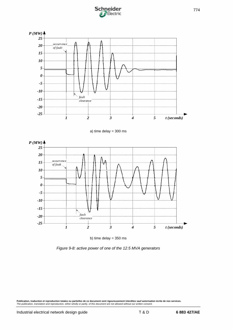
� active power analysis (see fig. 9-8)
The moment the fault occurs, the active power supplied by the generator greatly decreasesand remains at a very low value throughout the duration of the fault.
When the fault is cleared, an active power oscillation occurs which corresponds to theexchanges between this generator, the other generator and the public distribution network.This exchange of power corresponds to the power required for synchronism to be recoveredbetween the generator voltage and the distribution network voltage. If the protections areactivated after 300 ms (fault cleared by the circuit-breaker 40 ms later), the power oscillations(alternately positive and negative values) rapidly decrease becoming stabilised at the initialvalue (see fig. 9-8-a). On the other hand, in the case of activation after 350 ms, the oscillationscontinue without presenting a significant decrease; the generator is not capable of recoveringsynchronism (see fig. 9-8-b).
774
Publication, traduction et reproduction totales ou partielles de ce document sont rigoureusement interdites sauf autorisation écrite de nos services.The publication, translation and reproduction, either wholly or partly, of this document are not allowed without our written consent.
Industrial electrical network design guide T & D 6 883 427/AE
P (MW)25
20
15
10
5
0
-5
-10
-15
-20
-251 2 3 4 5 t (seconds)
occurrenceof fault
faultclearance
a) time delay = 300 ms
P (MW)25
20
15
10
5
0
-5
-10
-15
-20
-251 2 3 4 5 t (seconds)
occurrenceof fault
faultclearance
b) time delay = 350 ms
Figure 9-8: active power of one of the 12.5 MVA generators

775
Publication, traduction et reproduction totales ou partielles de ce document sont rigoureusement interdites sauf autorisation écrite de nos services.The publication, translation and reproduction, either wholly or partly, of this document are not allowed without our written consent.
Industrial electrical network design guide T & D 6 883 427/AE
� reactive power analysis (see fig. 9-9)
When the fault occurs, the reactive power greatly increases and remains at a high valuethroughout the duration of the fault, roughly 2.7 times the value before the fault occurred. Itincreases again when the fault is cleared owing to the return of the voltage to a normal value.Indeed, the loads then have a great need of reactive power in order to recover their normalmagnetizing flux. If the protections are activated after 350 ms, the loss of synchronismprevents the reactive power from stabilising (see fig. 9-9-b).
Q (Mvar)20
16
12
8
4
0
-4
-81 2 3 4 5 t (seconds)
occurrenceof fault
faultclearance
a) time delay = 300 ms
Q (Mvar)20
16
12
8
4
0
-4
-81 2 3 4 5 t (seconds)
occurrenceof fault
faultclearance
b) time delay = 350 ms
Figure 9-9: reactive power of one of the 12.5 MVA generators

776
Publication, traduction et reproduction totales ou partielles de ce document sont rigoureusement interdites sauf autorisation écrite de nos services.The publication, translation and reproduction, either wholly or partly, of this document are not allowed without our written consent.
Industrial electrical network design guide T & D 6 883 427/AE
� speed analysis (see fig. 9-10)
When the short circuit occurs, the speed increases as the network active power demand isvery low while the turbines continue to supply mechanical power.
Clearance of the fault leads to the generator slowing down and its speed begins to oscillate.
If the protections are activated after 350 ms (see fig. 9-10-b), the generator does not recover astable operating state.
1.039
1.017
1
0.984
0.962
0.9401 2 3 4 5 t (seconds)
NNs
occurrenceof fault
faultclearance
a) time delay = 300 ms
1.039
1.017
1
0.984
0.962
0.9401 2 3 4 5 t (seconds)
NNs
occurrenceof fault
faultclearance
b) time delay = 350 ms
Figure 9-10: speed of one of the 12.5 MVA generators

777
Publication, traduction et reproduction totales ou partielles de ce document sont rigoureusement interdites sauf autorisation écrite de nos services.The publication, translation and reproduction, either wholly or partly, of this document are not allowed without our written consent.
Industrial electrical network design guide T & D 6 883 427/AE
� voltage analysis (see fig. 9-11)
If the protections are activated after 300 ms (see fig. 9-11-a), the voltage quickly recovers itsnominal value after clearance of the fault.
On the other hand, the voltage does not recover its nominal value and even tends to decreaseif the protections are activated after 350 ms (see fig. 9-11-b).
3500
2800
2100
1400
700
01 2 3 4 5 t (seconds)
U (V)
occurrenceof fault
faultclearance
a) time delay = 300 ms
3500
2800
2100
1400
700
01 2 3 4 5 t (seconds)
U (V)
occurrenceof fault
faultclearance
b) time delay = 350 ms
Figure 9-11: voltage of one of the 12.5 MVA generators

778
Publication, traduction et reproduction totales ou partielles de ce document sont rigoureusement interdites sauf autorisation écrite de nos services.The publication, translation and reproduction, either wholly or partly, of this document are not allowed without our written consent.
Industrial electrical network design guide T & D 6 883 427/AE
o current development (see fig. 9-12)
If the protections are activated after 300 ms, the current, just like the voltage, recovers its initialvalue (see fig. 9-12-a); however, it remains at a high average value if the protections areactivated after 350 ms (see fig. 9-12-b).
In the case of activation after 350 ms, the protections ensuring the safeguard of the generatormust cause it to be put out of service. This does not, however, ensure correct operation of theinstallation.
9000
7200
5400
3600
1800
01 2 3 4 5 t (seconds)
I (A)
occurrenceof fault
faultclearance
a) time delay = 300 ms
9000
7200
5400
3600
1800
01 2 3 4 5 t (seconds)
I (A)
occurrenceof fault
faultclearance
b) time delay = 350 ms
Figure 9-12: current of one of the 12.5 MVA generators

779
Publication, traduction et reproduction totales ou partielles de ce document sont rigoureusement interdites sauf autorisation écrite de nos services.The publication, translation and reproduction, either wholly or partly, of this document are not allowed without our written consent.
Industrial electrical network design guide T & D 6 883 427/AE
o behaviour of a motor
The behaviour of the motors is also representative of the instability observed when theprotection time delay is too long.When it is equal to 350 ms, in spite of the fault being cleared, the speed of the motorcontinues to decrease (see fig. 9-13-b), and the current absorbed is maintained at an averagevalue close to 2 In (see fig. 9-14-b).
This operation is critical for the motor (overheating of the windings) and may be dangerous forthe machine driven. It is essential that the protections put the motor out of service.
1
0.998
0.976
0.964
0.952
0.9401 2 3 4 5 t (seconds)
NNs
occurrenceof fault
faultclearance
a) time delay = 300 ms
1
0.96
0.92
0.88
0.84
0.81 2 3 4 5 t (seconds)
NNs
occurrenceof fault
faultclearance
b) time delay = 350 ms
Figure 9-13: speed of one of the 5.5 MVA motors

780
Publication, traduction et reproduction totales ou partielles de ce document sont rigoureusement interdites sauf autorisation écrite de nos services.The publication, translation and reproduction, either wholly or partly, of this document are not allowed without our written consent.
Industrial electrical network design guide T & D 6 883 427/AE
2500
2000
1500
1000
500
01 2 3 4 5 t (seconds)
I (A)
occurrenceof fault
faultclearance
a) time delay = 300 ms
occurrenceof fault
2500
2000
1500
1000
500
01 2 3 4 5 t (seconds)
I (A)
faultclearance
b) time delay = 350 ms
Figure 9-14: current of one of the 5.5 MVA motors

781
Publication, traduction et reproduction totales ou partielles de ce document sont rigoureusement interdites sauf autorisation écrite de nos services.The publication, translation and reproduction, either wholly or partly, of this document are not allowed without our written consent.
Industrial electrical network design guide T & D 6 883 427/AE
n conclusions of the study
The study of the impact of a three-phase short circuit on the 63/20 kV transformer secondaryshows that:
- setting the transformer protection time delay at 350 ms is unacceptable
- 300 ms is the maximum limit
- 250 ms allows a security margin.

782
Publication, traduction et reproduction totales ou partielles de ce document sont rigoureusement interdites sauf autorisation écrite de nos services.The publication, translation and reproduction, either wholly or partly, of this document are not allowed without our written consent.
Industrial electrical network design guide T & D 6 883 427/AE
CHAPTER 9 BIBLIOGRAPHY
n standards
o EN 50160 (05.1995): voltage characteristics of electricity supplied by public distributionsystems
n Schneider cahiers techniques
o MV public distribution networks throughout the world, Cahier Technique n° 155,Ch. Puret
o Automatic changeover switching on L.V. and H.V. network supplies, Cahier Technique n° 75, G. Thomasset
o Control, monitoring and protection of HV motors, Cahier Technique n° 165, JY. Blanc
o HV industrial network design, Cahier Technique n° 169, G. Thomasset
o Protection of industrial and commercial MV networks, Cahier Technique n° 174, A. Sastré