8.3.2 Parameter Setting of the FOCAS1/Ethernet Function 8 ... · Set the TCP/IP–related items of...
22
8. EMBEDDED ETHERNET FUNCTION B–63525EN/02 614 When configuring a large network or expanding an existing network, consult with your network manager to set an IP address, subnet mask, and router IP address. This subsection describes the settings required to operate the FOCAS1/Ethernet function (or DNC1/Ethernet function) when the embedded Ethernet function for the Series 16i/18i/21i/160i/180i/210i/ 160is/180is/210is–B is used. CAUTION When using the embedded Ethernet function for the first time, make various settings including IP address setting carefully and conduct a communication test sufficiently, consulting with your network manager. Note that if an incorrect IP address is set, for example, the entire network can suffer from a communication error. NOTE 1 The FOCAS1/Ethernet function allows up to five FOCAS1/ Ethernet clients to be connected to one CNC. 2 If multiple application software products or multiple personal computers access the CNC simultaneously, the communication load on the CNC can increase, resulting in decreased communication speed and degraded CNC screen display processing. 8.3.1.5 Configuring a large network 8.3.2 Parameter Setting of the FOCAS1/Ethernet Function 8.3.2.1 Notes on using the FOCAS1/Ethernet function for the first time
Transcript of 8.3.2 Parameter Setting of the FOCAS1/Ethernet Function 8 ... · Set the TCP/IP–related items of...

8. EMBEDDED ETHERNET FUNCTION B–63525EN/02
614
When configuring a large network or expanding an existing network,consult with your network manager to set an IP address, subnet mask, androuter IP address.
This subsection describes the settings required to operate theFOCAS1/Ethernet function (or DNC1/Ethernet function) when theembedded Ethernet function for the Series 16i/18i/21i/160i/180i/210i/160is/180is/210is–B is used.
CAUTION
When using the embedded Ethernet function for the firsttime, make various settings including IP address settingcarefully and conduct a communication test sufficiently,consulting with your network manager.Note that if an incorrect IP address is set, for example, theentire network can suffer from a communication error.
NOTE
1 The FOCAS1/Ethernet function allows up to five FOCAS1/Ethernet clients to be connected to one CNC.
2 If multiple application software products or multiplepersonal computers access the CNC simultaneously, thecommunication load on the CNC can increase, resulting indecreased communication speed and degraded CNCscreen display processing.
8.3.1.5
Configuring a large
network
8.3.2Parameter Setting ofthe FOCAS1/EthernetFunction
8.3.2.1
Notes on using the
FOCAS1/Ethernetfunction for the first time

B–63525EN/02 8. EMBEDDED ETHERNET FUNCTION
615
On the Ethernet parameter setting screen, set the parameters for operatingthe FOCAS1/Ethernet function.
Display
1 Place the CNC in the MDI mode.
2 Press the function key SYSTEM .
3 Press the continuous menu key at the right end of the soft key display.
4 Press the [ETHPRM] soft key. The Ethernet parameter setting screenappears. The Ethernet functions currently available are displayed
The upper row displays the usable embedded Ethernet functiondevice.The embedded port or PCMCIA card is displayed.The lower row displays the usable Ethernet option boards. When nooption board is installed, no information is displayed.
5 By pressing the [EMBEDD] soft key, the parameters for the embeddedEthernet port can be set.By pressing the [PCMCIA] soft key, the parameters for the PCMCIAEthernet card can be set.
NOTE
The parameters for the embedded Ethernet port and theparameters for the PCMCIA Ethernet card are independentof each other.
6 By using the MDI keys and soft keys, enter and update data.
7 Switch the screen display with the page keys PAGE
PAGE
.
8.3.2.2
FOCAS1/Ethernet
parameter setting screen
Procedure

8. EMBEDDED ETHERNET FUNCTION B–63525EN/02
616
If data is already registered, the data is displayed.

B–63525EN/02 8. EMBEDDED ETHERNET FUNCTION
617
Display item and setting items
The item related to the embedded Ethernet function is displayed.
Item Description
MAC ADDRESS Embedded Ethernet MAC address
Set the TCP/IP–related items of the embedded Ethernet.
Item Description
IP ADDRESS Specify the IP address of the embedded Ethernet.(Example of specification format: ”192.168.1.1”)
SUBNET MASK Specify a mask address for the IP addresses of the network.(Example of specification format: ”255.255.255.0”)
ROUTER IP ADDRESS
Specify the IP address of the router.Specify this item when the network contains a router.(Example of specification format: ”192.168.1.254”)
Set the items related to the FOCAS1/Ethernet function.
Item Description
PORT NUMBER(TCP)
Specify a port number to be used with the FOCAS1/Ethernetfunction. The valid input range is 5001 to 65535.When using a port number for the DNC1/Ethernet function, referto ”FANUC Personal Computer FA System Windows NT Ver-sion OPERATOR’S MANUAL (B–75044EN)”.
PORT NUMBER(UDP)
Specify this item when using the DNC1/Ethernet function.Specify a UDP port number for transmitting UDP broadcastdata.The valid input range is 5001 to 65535.For details, refer to ”FANUC Personal Computer FA SystemWindows NT Version OPERATOR’S MANUAL (B–75044EN)”.Set 0 when using the FOCAS1/Ethernet function or when trans-mitting no UDP broadcast data.
TIME INTERVAL(NOTE 1)
Specify this item when using the DNC1/Ethernet function.Specify a time interval at which UDP broadcast data specifiedabove with a UDP port number is transmitted. The unit is 10 ms. The valid input range is 10 to 65535. Thismeans that a value less than 100 ms cannot be specified.Set 0 when using the FOCAS1/Ethernet function or when trans-mitting no UDP broadcast data.Example)100: Broadcast data is transmitted at intervals of one second[1000 ms] (= 100 � 10).
Display item related tothe embedded Ethernetfunction
Embedded EthernetTCP/IP setting items
FOCAS1/Ethernet settingitems

8. EMBEDDED ETHERNET FUNCTION B–63525EN/02
618
NOTE
1 When a small value is set for the item of time interval,communication load increases, and the performance of thenetwork can be adversely affected.
2 The parameters for the PCMCIA Ethernet card are set to thefollowing default values before shipment:IP address: 192.168.1.1Subnet mask: 255.255.255.0Router IP address: NoneTCP port number: 8193UDP port number: 0Time interval: 0

B–63525EN/02 8. EMBEDDED ETHERNET FUNCTION
619
An example of minimum setting required to operate theFOCAS1/Ethernet function on a small network is provided below.In this example, one personal computer is connected to two CNCsthrough FOCAS1/Ethernet.
� On Personal Computer 1, the client of the FOCAS1/Ethernet functionoperates.
� On CNC 1 and CNC 2, the server of the FOCAS1/Ethernet functionoperates
10BASE–T or 100BASE–TX
CNC 1 CNC 2 PC 1
CNC 1 CNC 2
IP address 192.168.1.1 192.168.1.2
Subnet mask 255.255.255.0 255.255.255.0
Router IP address None None
TCP port number 8193 8193
UDP port number 0 0
Time interval 0 0
PC 1
IP address 192.168.1.101
Subnet mask 255.255.255.0
Default gateway None
CNC 1 NC IP address 192.168.1.1
NC TCP port number 8193
CNC 2 NC IP address 192.168.1.2
NC TCP port number 8193
8.3.2.3
Using the
FOCAS1/Ethernetfunction on a smallnetwork
The Ethernet parameter screen is used forsetting.
”Microsoft TCP/IP property” of the personal computer(Windows 95/98/NT/2000) is used for setting.
The arguments of the data window library functioncnc_allclibhndl3 are used for setting.

8. EMBEDDED ETHERNET FUNCTION B–63525EN/02
620
An example of minimum setting required to operate the DNC1/Ethernetfunction on a small network is provided below.In this example, one personal computer is connected to two CNCsthrough DNC1/Ethernet.
� On Personal Computer 1, the client of the DNC1/Ethernet functionoperates.
� On CNC 1 and CNC 2, the server of the DNC1/Ethernet functionoperates.
10BASE–T or 100BASE–TX
CNC 1 CNC 2 PC 1
CNC 1 CNC 2
IP address 192.168.1.1 192.168.1.2
Subnet mask 255.255.255.0 255.255.255.0
Router IP address None None
TCP port number 8193 8193
UDP port number 8192 8192
Time interval 100 100
PC 1
IP address 192.168.1.101
Subnet mask 255.255.255.0
Default gateway None
FANUC_C4_SERVER 8192/udp
CNC 1 Machine No. 1
NC IP address 192.168.1.1
NC TCP port number 8193
CNC 2 Machine No. 2
NC IP address 192.168.1.2
NC TCP port number 8193
8.3.2.4
Using the DNC1/Ethernet
function on a smallnetwork
The Ethernet parameter screen is used forsetting.
”Microsoft TCP/IP property” of the personal computer(Windows NT) is used for setting.
Refer to ”FANUC Personal Computer FA System Win-dows NT Version OPERATOR’S MANUAL”.
B–63525EN/02 8. EMBEDDED ETHERNET FUNCTION
621
When configuring a large network or expanding an existing network,consult with your network manager to set an IP address, subnet mask, androuter IP address.
This subsection describes the settings required to operate the FTP filetransfer function when the embedded Ethernet function for the Series16i/18i/21i/160i/180i/210i/160is/180is/210is–B is used.
CAUTION
When using the embedded Ethernet function for the firsttime, make various settings including IP address settingcarefully and conduct a communication test sufficiently,consulting with your network manager.Note that if an incorrect IP address is set, for example, theentire network can suffer from a communication error.
NOTE
With the FTP file transfer function, only one FTP sessioncan be established with one CNC.
8.3.2.5
Configuring a large
network
8.3.3Parameter Setting ofthe FTP File TransferFunction
8.3.3.1
Notes on using the FTP
file transfer function forthe first time
8. EMBEDDED ETHERNET FUNCTION B–63525EN/02
622
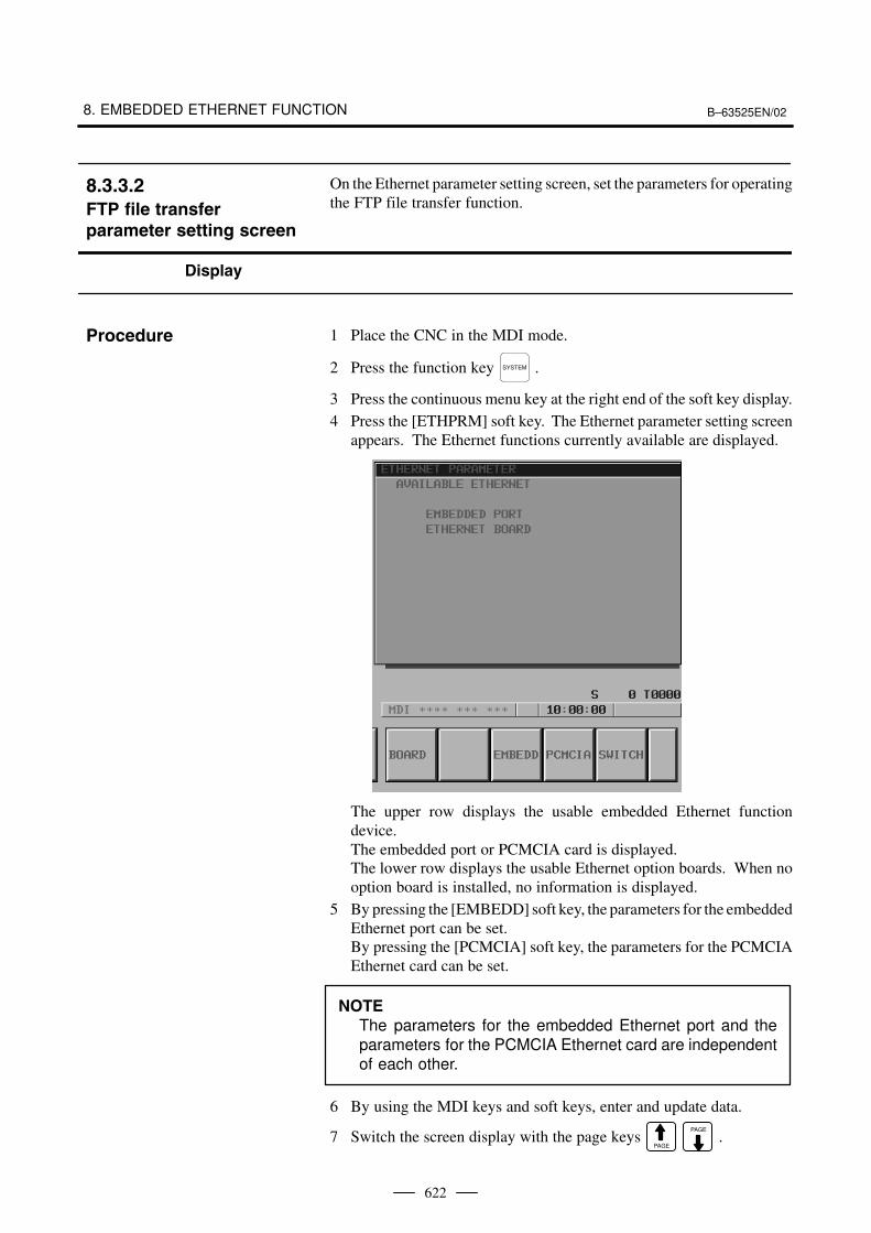
On the Ethernet parameter setting screen, set the parameters for operatingthe FTP file transfer function.
Display
1 Place the CNC in the MDI mode.
2 Press the function key SYSTEM .
3 Press the continuous menu key at the right end of the soft key display.
4 Press the [ETHPRM] soft key. The Ethernet parameter setting screenappears. The Ethernet functions currently available are displayed.
The upper row displays the usable embedded Ethernet functiondevice.The embedded port or PCMCIA card is displayed.The lower row displays the usable Ethernet option boards. When nooption board is installed, no information is displayed.
5 By pressing the [EMBEDD] soft key, the parameters for the embeddedEthernet port can be set.By pressing the [PCMCIA] soft key, the parameters for the PCMCIAEthernet card can be set.
NOTE
The parameters for the embedded Ethernet port and theparameters for the PCMCIA Ethernet card are independentof each other.
6 By using the MDI keys and soft keys, enter and update data.
7 Switch the screen display with the page keys PAGE
PAGE
.
8.3.3.2
FTP file transfer
parameter setting screen
Procedure

B–63525EN/02 8. EMBEDDED ETHERNET FUNCTION
623
If data is already registered, the data is displayed.

8. EMBEDDED ETHERNET FUNCTION B–63525EN/02
624
Display item and setting items
The item related to the embedded Ethernet function is displayed.
Item Description
MAC ADDRESS Embedded Ethernet MAC address
Set the TCP/IP–related items of the embedded Ethernet.
Item Description
IP ADDRESS Specify the IP address of the embedded Ethernet.(Example of specification format: ”192.168.1.1”)
SUBNET MASK Specify a mask address for the IP addresses of the network.(Example of specification format: ”255.255.255.0”)
ROUTER IP ADDRESS
Specify the IP address of the router.Specify this item when the network contains a router.(Example of specification format: ”192.168.1.254”)
Make settings related to the FTP file transfer function.Settings for up to three host computers can be made.
Item Description
PORT NUMBER Specify a port number to be used with the FTP file transfer func-tion.An FTP session is used, so that ”21” is to be specified usually.
IP ADDRESS Specify the IP address of the host computer.(Example of specification format: ”192.168.1.150”)
USERNAME Specify a user name to be used for logging in to the host com-puter with FTP.(Up to 31 characters can be specified.)
PASSWORD Specify a password for the user name specified above.Be sure to set a password.(Up to 31 characters can be specified.)
LOGIN DIR Specify a work directory to be used when logging in to the hostcomputer.(Up to 127 characters can be specified.)
Display item related tothe embedded Ethernetfunction
Embedded EthernetTCP/IP setting items
FTP file transfer settingitems

B–63525EN/02 8. EMBEDDED ETHERNET FUNCTION
625
The NC parameters related to the FTP file transfer function are describedbelow.
0020 I/O CHANNEL: Input/output device selection
[Data type] Byte
[Valid data range] 9: Select the embedded Ethernet as the input/output device.
0931 Special character (No. 1)
0932 Special character (No. 2)
0933 Special character (No. 3)
0934 Special character (No. 4)
0935 Special character (No. 5)
[Data type] Byte
[Valid data range] 32 to 126
NC parameters No. 931 to No. 935 enable soft keys to substitute forcharacters unavailable with the MDI keys.When a number other than 0 is set in each of these parameters, [CHAR–1]to [CHAR–5] are displayed in the input soft keys for special characters.
Example) When 33 is set in parameter No. 931, pressing the [CHAR–1]soft key enters ”!”.
8.3.3.3
Parameters
Parameters
8. EMBEDDED ETHERNET FUNCTION B–63525EN/02
626
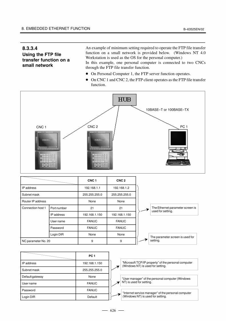
An example of minimum setting required to operate the FTP file transferfunction on a small network is provided below. (Windows NT 4.0Workstation is used as the OS for the personal computer.)In this example, one personal computer is connected to two CNCsthrough the FTP file transfer function.
� On Personal Computer 1, the FTP server function operates.
� On CNC 1 and CNC 2, the FTP client operates as the FTP file transferfunction.
10BASE–T or 100BASE–TX
CNC 1 CNC 2 PC 1
CNC 1 CNC 2
IP address 192.168.1.1 192.168.1.2
Subnet mask 255.255.255.0 255.255.255.0
Router IP address None None
Connection host 1 Port number 21 21
IP address 192.168.1.150 192.168.1.150
User name FANUC FANUC
Password FANUC FANUC
Login DIR None None
NC parameter No. 20 9 9
PC 1
IP address 192.168.1.150
Subnet mask 255.255.255.0
Default gateway None
User name FANUC
Password FANUC
Login DIR Default
8.3.3.4
Using the FTP file
transfer function on asmall network
The Ethernet parameter screen isused for setting.
The parameter screen is used forsetting.
”Microsoft TCP/IP property” of the personal computer(Windows NT) is used for setting.
”User manager” of the personal computer (WindowsNT) is used for setting.
”Internet service manager” of the personal computer(Windows NT) is used for setting.

B–63525EN/02 8. EMBEDDED ETHERNET FUNCTION
627
When configuring a large network or expanding an existing network,consult with your network manager to set an IP address, subnet mask, androuter IP address.
This subsection describes the method of parameter input when theembedded Ethernet function for the Series 16i/18i/21i/160i/180i/210i/160is/180is/210is–B is used.
Basic method of data input
The basic method of data input is described below, using an example ofIP address input.
1 Place the CNC in the MDI mode.
2 Display the Ethernet parameter screen.
3 Move the cursor to a desired input item with cursor keys.
4 Type data with MDI keys.
5 Press the [INPUT] soft key or the function key INPUT to enter the data.
NOTEWhen deleting numeric data already set, enter 0. Whendeleting character data already set, enter SP (space).
Example) Setting 192.168.1.1 as IP address data
(a) Move the cursor to the item of IP address.
8.3.3.5
Configuring a large
network
8.3.4CommunicationParameter InputMethod
Procedure
8. EMBEDDED ETHERNET FUNCTION B–63525EN/02
628
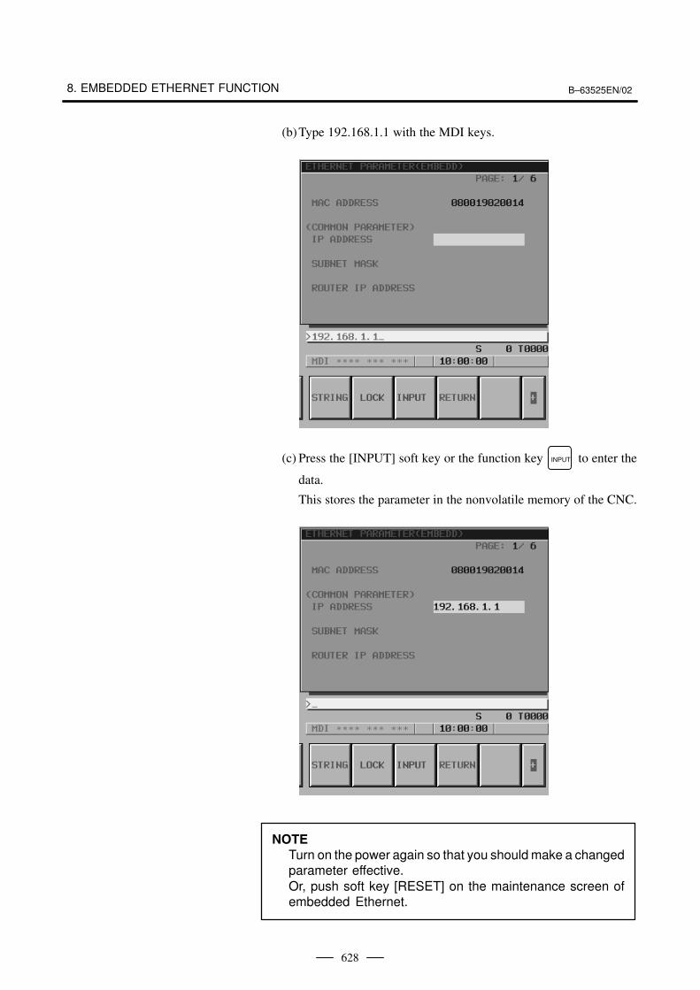
(b)Type 192.168.1.1 with the MDI keys.
(c) Press the [INPUT] soft key or the function key INPUT to enter the
data.
This stores the parameter in the nonvolatile memory of the CNC.
NOTE
Turn on the power again so that you should make a changedparameter effective.Or, push soft key [RESET] on the maintenance screen ofembedded Ethernet.

B–63525EN/02 8. EMBEDDED ETHERNET FUNCTION
629
Method of lowercase character input
The method of entering lowercase characters when specifying a username, password, and login DIR is described below.
1 Place the CNC in the MDI mode.
2 Display the Ethernet parameter screen.
3 Move the cursor to a desired input item with cursor keys.
4 When the [UNLOCK] soft key is displayed, uppercase characters areactually entered through MDI keys. For lowercase character input,press the [UNLOCK] soft key. The soft key display changes from[UNLOCK] to [LOCK].
5 Then, press the MDI keys A through Z. All of these characters areentered as lowercase characters.
6 To enter uppercase characters, press the [LOCK] soft key.
Method of entering a long character string
The method of entering a character string longer than 32 characters forspecifying a login DIR is described below.As an example, the processing for setting the character string”/NCDATA/NCPROGRAM/LINE001/GROUP002” is described.
1 Place the CNC in the MDI mode.
2 Display the Ethernet parameter screen.
Procedure
Procedure

8. EMBEDDED ETHERNET FUNCTION B–63525EN/02
630
3 Move the cursor to LOGIN DIR with cursor keys.
4 Press the [STRING] soft key. The cursor position and soft key displaychange as shown below.
B–63525EN/02 8. EMBEDDED ETHERNET FUNCTION
631
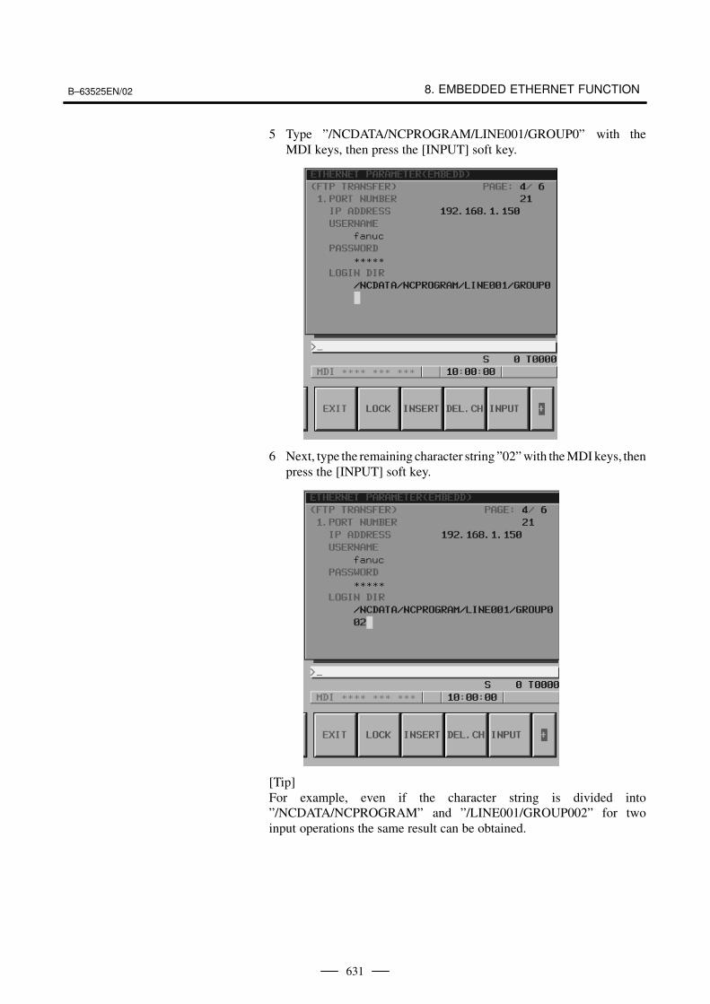
5 Type ”/NCDATA/NCPROGRAM/LINE001/GROUP0” with theMDI keys, then press the [INPUT] soft key.
6 Next, type the remaining character string ”02” with the MDI keys, thenpress the [INPUT] soft key.
[Tip]For example, even if the character string is divided into”/NCDATA/NCPROGRAM” and ”/LINE001/GROUP002” for twoinput operations the same result can be obtained.

8. EMBEDDED ETHERNET FUNCTION B–63525EN/02
632
7 To insert ”/FACTORY0010” between ”NCPROGRAM” and”/LINE001”, move the cursor to ”/” prefixed to ”LINE001” then type”/FACTORY0010” with the MDI keys. Finally, press the [INSERT]soft key.
8 To delete a character, move the cursor to the character to be deleted,then press the [DEL.CH] soft key. This operation deletes a characteron which the cursor is placed one at a time.
9 To overwrite a character, move the cursor to the character to beoverwritten, then type a desired character with the MDI key. Finally,press the [INPUT] soft key. This operation overwrites a character onwhich the cursor is placed.
10 Upon completion of character string input, press the [RETURN] softkey. This operation returns the cursor position and soft key display tothe state of step 1, and stores the set data in the nonvolatile memoryof the CNC.
B–63525EN/02 8. EMBEDDED ETHERNET FUNCTION
633
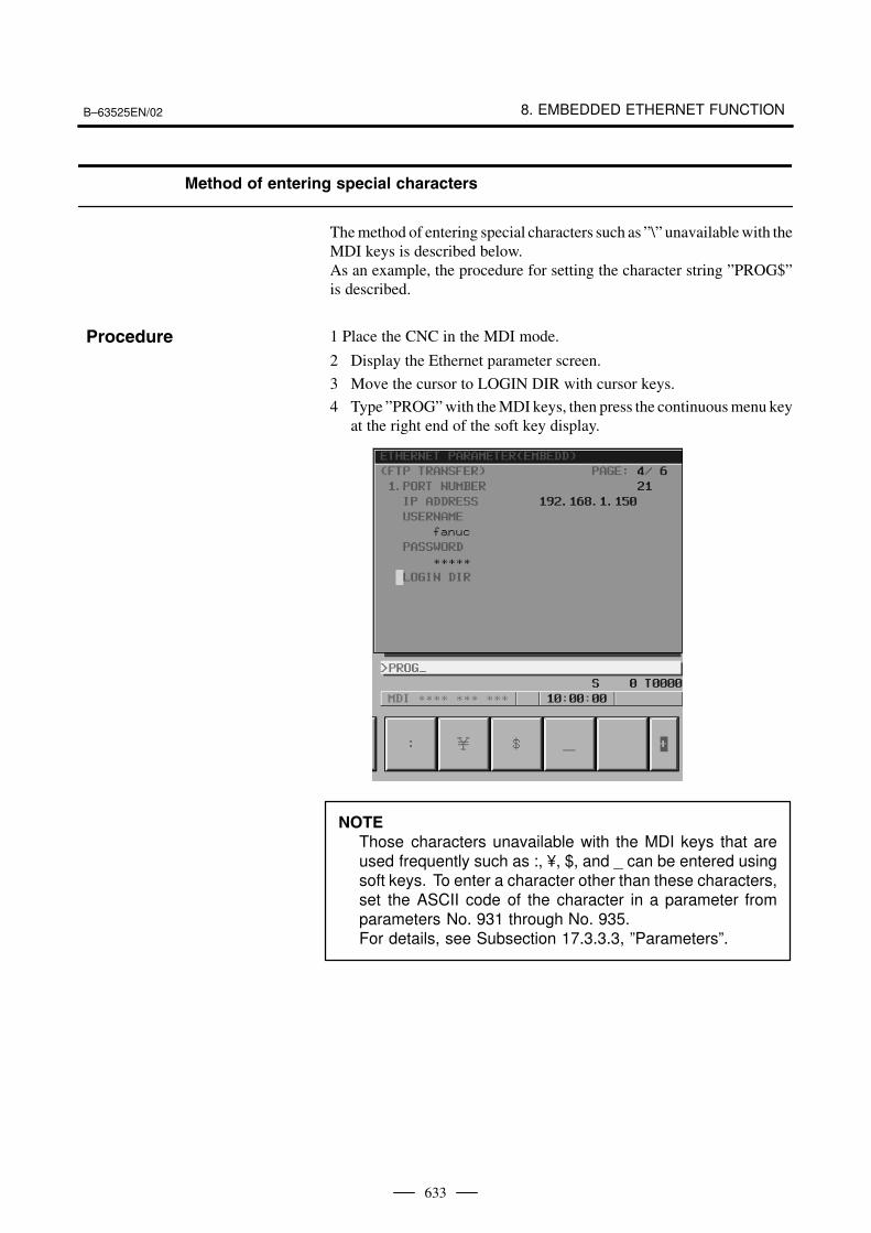
Method of entering special characters
The method of entering special characters such as ”\” unavailable with theMDI keys is described below.As an example, the procedure for setting the character string ”PROG$”is described.
1 Place the CNC in the MDI mode.
2 Display the Ethernet parameter screen.
3 Move the cursor to LOGIN DIR with cursor keys.
4 Type ”PROG” with the MDI keys, then press the continuous menu keyat the right end of the soft key display.
NOTE
Those characters unavailable with the MDI keys that areused frequently such as :, ¥, $, and _ can be entered usingsoft keys. To enter a character other than these characters,set the ASCII code of the character in a parameter fromparameters No. 931 through No. 935.For details, see Subsection 17.3.3.3, ”Parameters”.
Procedure

8. EMBEDDED ETHERNET FUNCTION B–63525EN/02
634
5 Press the [$] soft key.
6 Press the [INPUT] soft key.

B–63525EN/02 8. EMBEDDED ETHERNET FUNCTION
635
There are two types of embedded Ethernet devices: the embeddedEthernet port and PCMCIA Ethernet card.
Screen operation is required to switch between these two types of devices.
1 Place the CNC in the MDI mode.
2 Press the function key SYSTEM .
3 Press the continuous menu key at the right end of the soft key display.
4 Press the [ETHPRM] soft key. The Ethernet parameter setting screenappears. The Ethernet functions currently available are displayed.
The upper row displays the usable embedded Ethernet functiondevice.The embedded port or PCMCIA card is displayed.The lower row displays the usable Ethernet option boards. When nooption board is installed, no information is displayed.
8.4SWITCHING
BETWEEN THEEMBEDDED
ETHERNET DEVICES
Procedure