827994 thermocouple
9
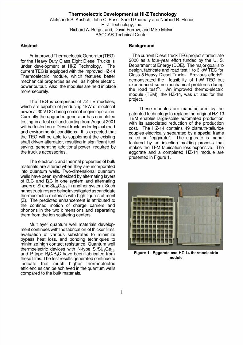
1 Figure 1. Eggcrate a nd HZ-14 t hermoelectric module Thermoelect ric Development at Hi-Z Technology Aleksandr S. Kushch, John C. Bass, Saeid Ghamaty and Norbert B. Elsner Hi-Z Technology, Inc. Richard A. Bergstrand, David Furrow, and Mike Melvin PACCAR Technical Center Abstract A n improved Thermoelectric Generator (TEG) for the Heavy Duty Class Eight Diesel Trucks is under development at Hi-Z Technology. The current TEG is equipped with the improved HZ- 14 Thermoelectric module, which features better mechanical properties as well as higher electric power output. Also, the modules are held in place more securely. The TEG is comprised of 72 TE modules, which are capable of producing 1kW of electrical power at 30 V DC during nominal engine operation. Currently the upgraded generator has completed testing in a test cell and starting from August 2001 will be tested on a Diesel truck under typical road and env ironmental conditions. It is expected that the TEG will be able to supplement the existing shaft driven alternator, resulting in significant fuel saving, generating additional power required by the truck’s accessories. The electronic and thermal properties of bulk materials are altered when they are incorporated into quantum wells. Two-dimensional quantum wells have been synthesized by alternating layers of B 4 C and B 9 C in one system and alternating layers of Si and Si 0.8 Ge 0.2 in another system. Such nanostructures are being investigated as candidate thermoelectric materials with high figures of merit (Z). The predicted enhancement is attributed to the confined motion of charge carriers and phonons in the two dimensions and separating them from the ion scattering centers. Multilayer quantum well materials develop- ment continues with the fabrication of thicker films, evaluation of various substrates to minimize bypass heat loss, and bonding techniques to minimize high contact resistance. Quantum well thermoelectric devices with N-type Si/Si 0.8 Ge 0.2 and P-type B 4 C/B 9 C have been fabricated from these films. The test results generated continue to indicate that much higher thermoelectric efficienci es can be achieved in the quantum wells compared to the bulk materials. Background The current Diesel truck TEG project started la te 2000 as a four-year effort funded by the U. S. Department of Energy (DOE). The major goal is t o design, fabricate and road test 1 to 3 kW TEG for Class 8 Heavy Diesel Trucks. Previous efforts (1) demonstrated the feasibility of 1kW TEG but experienced some mechanical problems during the road test (2) . An improved thermo-electric module (TEM), the HZ-14, was utilized for this project. These modules are manufactured by the patented technology to replace the original HZ-13 TEM enables large-scale automated production with its associated reduction of the production cost. The HZ-14 contains 49 bismuth-telluride couples electrically separated by a special frame called an “eggcrate”. The eggcrate is manu- factured by an injection molding process that makes the TE M fabr ication less expensive. The eggcrate and a completed HZ-14 module are presented in Figure 1.
-
Upload
srinivasan-venugopalan -
Category
Documents
-
view
231 -
download
0
Transcript of 827994 thermocouple
8/3/2019 827994 thermocouple
http://slidepdf.com/reader/full/827994-thermocouple 1/9
1
Figure 1. Eggcrate and HZ-14 thermoelectricmodule
Thermoelectric Development at Hi-Z TechnologyAleksandr S. Kushch, John C. Bass, Saeid Ghamaty and Norbert B. Elsner
Hi-Z Technology, Inc.Richard A. Bergstrand, David Furrow, and Mike Melvin
PACCAR Technical Center
Abstract
An improved Thermoelectric Generator (TEG)
for the Heavy Duty Class Eight Diesel Trucks isunder development at Hi-Z Technology. Thecurrent TEG is equipped with the improved HZ-14Thermoelectric module, which features bettermechanical properties as well as higher electricpower output. Also, the modules are held in placemore securely.
The TEG is comprised of 72 TE modules,which are capable of producing 1kW of electricalpower at 30 V DC during nominal engine operation.Currently the upgraded generator has completed
testing in a test cell and starting from August 2001will be tested on a Diesel truck under typical roadand environmental conditions. It is expected thatthe TEG will be able to supplement the existingshaft driven alternator, resulting in significant fuelsaving, generating additional power required bythe truck’s accessories.
The electronic and thermal properties of bulkmaterials are altered when they are incorporatedinto quantum wells. Two-dimensional quantumwells have been synthesized by alternating layers
of B4C and B9C in one system and alternatinglayers of Si and Si0.8Ge0.2 in another system. Suchnanostructures are being investigated as candidatethermoelectric materials with high figures of merit(Z). The predicted enhancement is attributed tothe confined motion of charge carriers andphonons in the two dimensions and separatingthem from the ion scattering centers.
Multilayer quantum well materials develop-ment continues with the fabrication of thicker films,evaluation of various substrates to minimizebypass heat loss, and bonding techniques tominimize high contact resistance. Quantum wellthermoelectric devices with N-type Si/Si0.8Ge0.2and P-type B4C/B9C have been fabricated fromthese films. The test results generated continue toindicate that much higher thermoelectricefficiencies can be achieved in the quantum wellscompared to the bulk materials.
Background
The current Diesel truck TEG project started late
2000 as a four-year effort funded by the U. S.Department of Energy (DOE). The major goal is todesign, fabricate and road test 1 to 3 kW TEG forClass 8 Heavy Diesel Trucks. Previous efforts(1)
demonstrated the feasibility of 1kW TEG butexperienced some mechanical problems duringthe road test(2). An improved thermo-electricmodule (TEM), the HZ-14, was utilized for thisproject.
These modules are manufactured by thepatented technology to replace the original HZ-13TEM enables large-scale automated productionwith its associated reduction of the productioncost. The HZ-14 contains 49 bismuth-telluridecouples electrically separated by a special framecalled an “eggcrate”. The eggcrate is manu-factured by an injection molding process thatmakes the TEM fabrication less expensive. Theeggcrate and a completed HZ-14 module arepresented in Figure 1.

8/3/2019 827994 thermocouple
http://slidepdf.com/reader/full/827994-thermocouple 2/9
2
0
1
2
3
4
0
2 4
6
8
10
12
14
0 2 4 6 8 10 12 14 16 Current (Amps)
Current - Voltage CurvesHZ-14 with 200°C Temp Difference
Voltage
Power
Figure 2. ÄT vs. Open Circuit Voltage
Figure 3. Power vs. Open Circuit Voltage
Figure 4. Electronic LoadingDevice
A set of 72 TEM (8 arrays with 9 module ineach array) was selected for this project byperformance and thickness. The TEM thicknessvariation for each array was less than 0.001" toensure uniform compression of the modules.
In order to prevent TEM lateral movementaluminum strips (0.032" thick) were epoxy bondedto the heat sinks on each side of the module. In
addition, RTV was applied to the heat sink at theTEM corner.
A new high temperature thermally conductivegrease was formulated and tested at Hi-Z. It hasdemonstrated superior performance at the TEMhot side operating temperature (about 250 - 275°C)and was selected for the TEG assembling.
TEG Hot Air Test
Prior to in-cell testing, the TEG was tested at Hi-Z with the hot air blower that simulated Dieselengine exhaust. The hot air blower (with integratedheater) is capable of supplying about 165 cfm of airheated up to 500°C. This test was conducted inorder to check the general functionality of the TEGand major subsystems such as electrical (array
interconnection, bus bars, terminals), coolingsystem and measurement system.
Two loading devices were designed andfabricated. The first one - electronic loading device(ELD) allows for fine-tuning the load and to settingthe optimal voltage/current conditions. The ELD isshown in Figure 4. The second loading device iscomprised of six car headlights, interconnected inparallel/series way to match the TEG resistance.
The TEG is equipped with the 12 thermo-couples that measure the temperatures at differentplaces the generator, such as hot and cold side ofthe TEMs, temperatures on the face of the heat
exchanger and heat sinks.One array of the TEMs (heat sink #1) has
special wiring that allows measuring open circuitvoltage and voltage under loading from individualmodules. These measurements indicate how
8/3/2019 827994 thermocouple
http://slidepdf.com/reader/full/827994-thermocouple 3/9
3
TEG Power, W
0
100
200
300
400
500
600
700
800
900
1000
0 50 100 150 200 250 300
Engine load, HP
T E G P o w e r , W
1300 RPM
1500 RPM
1700 RPM
1900 RPM
2100 RPM
2200 RPM
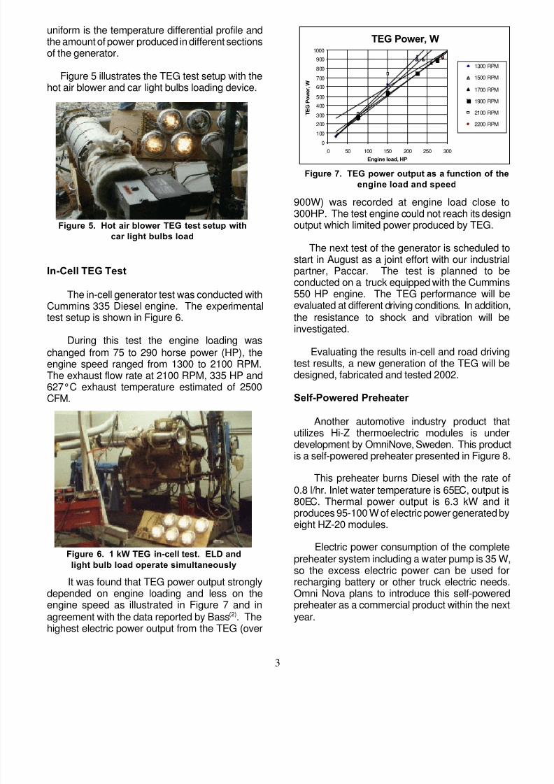
Figure 7. TEG power output as a function of theengine load and speed
Figure 5. Hot air blower TEG test setup withcar light bulbs load
Figure 6. 1 kW TEG in-cell test. ELD andlight bulb load operate simultaneously
uniform is the temperature differential profile andthe amount of power produced in different sectionsof the generator.
Figure 5 illustrates the TEG test setup with thehot air blower and car light bulbs loading device.
In-Cell TEG Test
The in-cell generator test was conducted withCummins 335 Diesel engine. The experimentaltest setup is shown in Figure 6.
During this test the engine loading waschanged from 75 to 290 horse power (HP), theengine speed ranged from 1300 to 2100 RPM.The exhaust flow rate at 2100 RPM, 335 HP and627°C exhaust temperature estimated of 2500CFM.
It was found that TEG power output stronglydepended on engine loading and less on theengine speed as illustrated in Figure 7 and inagreement with the data reported by Bass(2). Thehighest electric power output from the TEG (over
900W) was recorded at engine load close to300HP. The test engine could not reach its designoutput which limited power produced by TEG.
The next test of the generator is scheduled tostart in August as a joint effort with our industrial
partner, Paccar. The test is planned to beconducted on a truck equipped with the Cummins550 HP engine. The TEG performance will beevaluated at different driving conditions. In addition,the resistance to shock and vibration will beinvestigated.
Evaluating the results in-cell and road drivingtest results, a new generation of the TEG will bedesigned, fabricated and tested 2002.
Self-Powered Preheater
Another automotive industry product thatutilizes Hi-Z thermoelectric modules is underdevelopment by OmniNove, Sweden. This productis a self-powered preheater presented in Figure 8.
This preheater burns Diesel with the rate of0.8 l/hr. Inlet water temperature is 65EC, output is80EC. Thermal power output is 6.3 kW and itproduces 95-100 W of electric power generated byeight HZ-20 modules.
Electric power consumption of the completepreheater system including a water pump is 35 W,so the excess electric power can be used forrecharging battery or other truck electric needs.Omni Nova plans to introduce this self-poweredpreheater as a commercial product within the nextyear.
8/3/2019 827994 thermocouple
http://slidepdf.com/reader/full/827994-thermocouple 4/9
4
Figure 8. Self Powered Fluid Heater
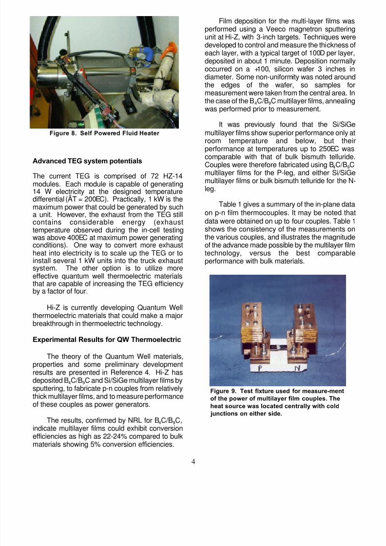
Figure 9. Test fixture used for measure-mentof the power of multilayer film couples. Theheat source was located centrally with cold
junctions on either side.
Advanced TEG system potentials
The current TEG is comprised of 72 HZ-14modules. Each module is capable of generating
14 W electricity at the designed temperaturedifferential (ÄT = 200EC). Practically, 1 kW is themaximum power that could be generated by sucha unit. However, the exhaust from the TEG stillcontains considerable energy (exhausttemperature observed during the in-cell testingwas above 400EC at maximum power generatingconditions). One way to convert more exhaustheat into electricity is to scale up the TEG or toinstall several 1 kW units into the truck exhaustsystem. The other option is to utilize moreeffective quantum well thermoelectric materials
that are capable of increasing the TEG efficiencyby a factor of four.
Hi-Z is currently developing Quantum Wellthermoelectric materials that could make a majorbreakthrough in thermoelectric technology.
Experimental Results for QW Thermoelectric
The theory of the Quantum Well materials,properties and some preliminary developmentresults are presented in Reference 4. Hi-Z has
deposited B4C/B9C and Si/SiGe multilayer films bysputtering, to fabricate p-n couples from relativelythick multilayer films, and to measure performanceof these couples as power generators.
The results, confirmed by NRL for B4C/B9C,indicate multilayer films could exhibit conversionefficiencies as high as 22-24% compared to bulkmaterials showing 5% conversion efficiencies.
Film deposition for the multi-layer films wasperformed using a Veeco magnetron sputteringunit at Hi-Z, with 3-inch targets. Techniques weredeveloped to control and measure the thickness ofeach layer, with a typical target of 100D per layer,deposited in about 1 minute. Deposition normallyoccurred on a +100, silicon wafer 3 inches indiameter. Some non-uniformity was noted aroundthe edges of the wafer, so samples for
measurement were taken from the central area. Inthe case of the B4C/B9C multilayer films, annealingwas performed prior to measurement.
It was previously found that the Si/SiGemultilayer films show superior performance only atroom temperature and below, but theirperformance at temperatures up to 250EC wascomparable with that of bulk bismuth telluride.Couples were therefore fabricated using B4C/B9Cmultilayer films for the P-leg, and either Si/SiGemultilayer films or bulk bismuth telluride for the N-
leg.Table 1 gives a summary of the in-plane data
on p-n film thermocouples. It may be noted thatdata were obtained on up to four couples. Table 1shows the consistency of the measurements onthe various couples, and illustrates the magnitudeof the advance made possible by the multilayer filmtechnology, versus the best comparableperformance with bulk materials.
8/3/2019 827994 thermocouple
http://slidepdf.com/reader/full/827994-thermocouple 5/9
5
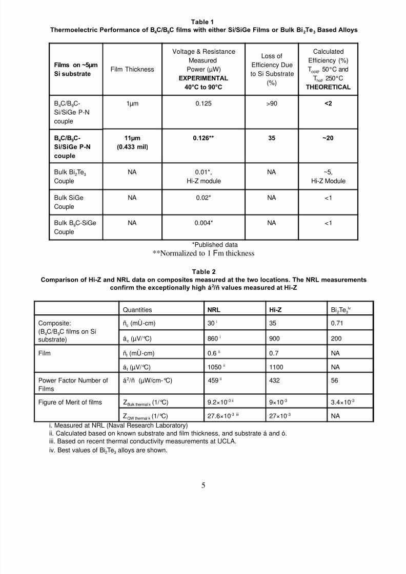
Table 1Thermoelectric Performance of B4C/B9C films with either Si/SiGe Films or Bulk Bi2Te3 Based Alloys
Films on ~5µmSi substrate
Film Thickness
Voltage & ResistanceMeasured
Power (µW)EXPERIMENTAL
40°C to 90°C
Loss ofEfficiency Dueto Si Substrate
(%)
CalculatedEfficiency (%)Tcold. 50°C and
Thot. 250°CTHEORETICAL
B4C/B9C-Si/SiGe P-Ncouple
1µm 0.125 >90 <2
B4C/B9C-Si/SiGe P-N
couple
11µm(0.433 mil)
0.126** 35 ~20
Bulk Bi2Te3
CoupleNA 0.01*,
Hi-Z moduleNA ~5,
Hi-Z Module
Bulk SiGeCouple NA 0.02* NA <1
Bulk B9C-SiGeCouple
NA 0.004* NA <1
*Published data**Normalized to 1 Fm thickness
Table 2Comparison of Hi-Z and NRL data on composites measured at the two locations. The NRL measurements
confirm the exceptionally high á2 /ñ values measured at Hi-Z
Quantities NRL Hi-Z Bi2Te3iv
Composite:(B4C/B9C films on Sisubstrate)
ñc (mÙ-cm) 30 i 35 0.71
ác (µV/°C) 860 i 900 200
Film ñf (mÙ-cm) 0.6 ii 0.7 NA
á f (µV/°C) 1050 ii 1100 NA
Power Factor Number ofFilms
á2 /ñ (µW/cm-°C) 459 ii 432 56
Figure of Merit of films ZBulk thermal k (1/°C) 9.2×10⁻³ ii 9×10⁻³ 3.4×10⁻³
ZQW thermal k (1/°C) 27.6×10⁻³ iii 27×10-3 NA
i. Measured at NRL (Naval Research Laboratory)ii. Calculated based on known substrate and film thickness, and substrate á and ó.iii. Based on recent thermal conductivity measurements at UCLA.iv. Best values of Bi2Te3 alloys are shown.
8/3/2019 827994 thermocouple
http://slidepdf.com/reader/full/827994-thermocouple 6/9
6
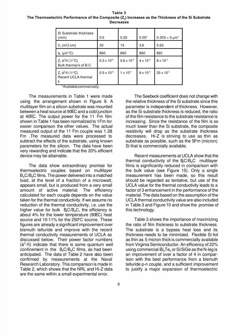
Table 3The Thermoelectric Performance of the Composite (Zc) Increases as the Thickness of the Si Substrate
Decreases
Si Substrate thickness(mm) 0.5 0.25 0.05* 0.005 = 5 µm*
ñc (mÙ-cm) 30 15 3.6 0.63
ác (µV/°C) 860 860 860 860
Zc á2 /ñ (1/°C)Bulk thermal k of B-C
0.3 x 10⁻³ 0.6 x 10⁻³ 4 x 10⁻³ 8 x 10⁻³
Zc á2 /ñ (1/°C)Recent UCLA thermalk
0.5 x 10⁻³ 1 x 10⁻³ 9 x 10⁻³ 25 x 10-3
*Available commercially.
The measurements in Table 1 were madeusing the arrangement shown in Figure 9. Amultilayer film on a silicon substrate was mountedbetween a heat source at 90EC and a cold junction
at 40EC. The output power for the 11 Fm filmshown in Table 1 has been normalized to 1Fm foreasier comparison the other values. The actualmeasured output of the 11 Fm couple was 1.38Fm .The measured data were processed tosubtract the effects of the substrate, using knownparameters for the silicon. The data have beenvery rewarding and indicate that the 20% efficientdevice may be attainable.
The data show extraordinary promise forthermoelectric couples based on multilayer
B4C/B9C films. The power delivered into a matchedload, at the level of a fraction of a microwatt,appears small, but is produced from a very smallamount of active material. The efficiencycalculated for each couple depends on the valuetaken for the thermal conductivity. If we assume noreduction of the thermal conductivity, i.e. use thehigher value for bulk B4C/B9C, the efficiency isabout 4% for the lower temperature (90EC) heatsource and 10-11% for the 250oC source. Thesefigures are already a significant improvement overbismuth telluride and improve with the recent
thermal conductivity measurements of UCLA asdiscussed below. Their power factor numbers(á2 /ñ) indicate that there is some quantum wellconfinement in the B4C/B9C films, as had beenanticipated. The data of Table 2 have also beenconfirmed by measurements at the NavalResearch Laboratory. This comparison is made inTable 2, which shows that the NRL and Hi-Z dataare the same within a small experimental error.
The Seebeck coefficient does not change withthe relative thickness of the Si substrate since thisparameter is independent of thickness. However,as the Si substrate thickness is reduced, the ratio
of the film resistance to the substrate resistance isincreasing. Since the resistance of the film is somuch lower than the Si substrate, the compositeresistivity will drop as the substrate thicknessdecreases. Hi-Z is striving to use as thin assubstrate as possible, such as the 5Fm (micron)Si that is commercially available.
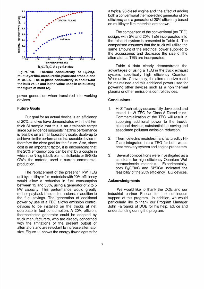
Recent measurements at UCLA show that thethermal conductivity of the B4C/B9C multilayerfilms is significantly reduced in comparison withthe bulk value (see Figure 15). Only a single
measurement has been made, so this resultshould be regarded as tentative, but use of theUCLA value for the thermal conductivity leads to afactor of 3 enhancement in the performance of thematerial. The data based on the assumption of theUCLA thermal conductivity value are also includedin Table 3 and Figure 10 and show the promise ofthis technology.
Table 3 shows the importance of maximizingthe ratio of film thickness to substrate thickness.The substrate is a bypass heat loss and its
thickness needs to be minimized. Flexible Si foilas thin as 5 micron thick is commercially availablefrom Virginia Semiconductor. An efficiency of 22%using commercial Bi2Te3 or Si/SiGe as the N-leg isan improvement of over a factor of 4 in compar-ison with the best performance from a bismuthtelluride p-n couple, and a sufficient improvementto justify a major expansion of thermoelectric
8/3/2019 827994 thermocouple
http://slidepdf.com/reader/full/827994-thermocouple 7/9
7
Figure 10. Thermal conductivity of B4C/B9Cmultilayer film, measured in-plane and cross-planeat UCLA. The in-plane conductivity is about1/3of the bulk value and is the value used in calculatingthe figure of merit (Z).
power generation when translated into working
devices.Future Goals
Our goal for an actual device is an efficiencyof 20%, and we have demonstrated with the 5 Fmthick Si sample that this is an attainable targetsince our evidence suggests that this performanceis feasible on a small laboratory scale. Scale-up toachieve similar performance in a useable device istherefore the clear goal for the future. Also, sincecost is an important factor, it is encouraging that
the 20% efficiency goal can be met by a couple inwhich the N-leg is bulk bismuth telluride or Si/SiGeQWs, the material used in current commercialproduction.
The replacement of the present 1 kW TEGunit by multilayer film materials with 20% efficiencywould allow a reduction in fuel consumptionbetween 12 and 30%, using a generator of 2 to 5kW capacity. This performance would greatlyreduce payback time and emissions, in addition tothe fuel savings. The generation of additional
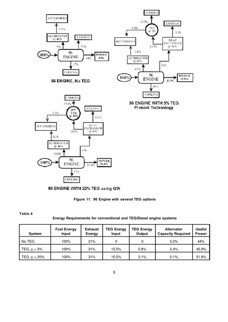
power by use of a TEG allows emission controldevices to be installed on the trucks at netdecrease in fuel consumption. A 20% efficientthermoelectric generator could be adopted bytruck manufacturers, who are already concernedwith the limitations of the present output ofalternators and are reluctant to increase alternatorsize. Figure 11 shows the energy flow diagram for
a typical 96 diesel engine and the affect of addingboth a conventional thermoelectric generator of 5%efficiency and a generator of 20% efficiency basedon multilayer film materials are shown.
The comparison of the conventional (no TEG)design, with 5% and 20% TEG incorporated intothe exhaust system is presented in Table 4. Thecomparison assumes that the truck will utilize the
same amount of the electrical power supplied tothe accessories and decrease the size of thealternator as TEG are incorporated.
Table 4 data clearly demonstrates theadvantages of using a TEG in the truck exhaustsystem, specifically high efficiency QuantumWells units. Conversely, the alternator size couldbe maintained and this additional power used forpowering other devices such as a non thermalplasma or other emissions control devices.
Conclusions
1. Hi-Z Technology successfully developed andtested 1 kW TEG for Class 8 Diesel truck.Commercialization of the TEG will result insupplying additional power to the truck’selectrical devices, substantial fuel saving andassociated pollutant emission reduction.
2. Thermoelectric modules manufactured by Hi-Z are integrated into a TEG for both wasteheat recovery system and engine preheaters.
3. Several compositions were investigated as acandidate for high efficiency Quantum Wellthermoelectric materials. Experimentally,both B4C/BeC and Si/SiGe indicated thefeasibility of the 20% efficiency TEG devices.
Acknowledgments
We would like to thank the DOE and ourindustrial partner Paccar for the continuoussupport of this program. In addition, we would
particularly like to thank our Program ManagerJohn Fairbanks of DOE for his help, advice andunderstanding during the program.
8/3/2019 827994 thermocouple
http://slidepdf.com/reader/full/827994-thermocouple 8/9
8
Figure 11. 96 Engine with several TEG options
Table 4Energy Requirements for conventional and TEG/Diesel engine systems
SystemFuel Energy
InputExhaustEnergy
TEG EnergyInput
TEG EnergyOutput
Alternator Capacity Required
UsefulPower
No TEG 100% 31% 0 0 3.2% 44%
TEG, ç = 5% 100% 31% 15.5% 0.8% 2.4% 45.9%
TEG, ç = 20% 100% 31% 15.5% 3.1% 0.1% 51.8%

8/3/2019 827994 thermocouple
http://slidepdf.com/reader/full/827994-thermocouple 9/9
9
References
4. Bass, J. C., Elsner, N. B. and Leavitt, F.A.,“Performance of the 1kW ThermoelectricGenerator for Diesel Engines”, 1994, 13th
International Conference on Thermo-electronics, Kansas City, MO, p. 295 - 298.
5. Bass, J.C., “Design and Test of Prototype1kW Generator for Diesel Engines” FinalReport, June 23, 1997, contract 500-90-025,California Energy Commission, EnergyTechnologies Advancement Program,Transportation Energy TechnologiesAdvancement Program. Leavitt, F.A., Elsner,N.B., Bass, J.C., “Use, Application and Testing ofthe HZ-14 Thermoelectric Modules”.
6. S. Ghamaty and N. Elsner, 1999,18th Intl.
Conf. Thermoelectrics, p. 485.