800 RAIL GRADE CROSSINGS Traffic Engineering Manual TABLE
22
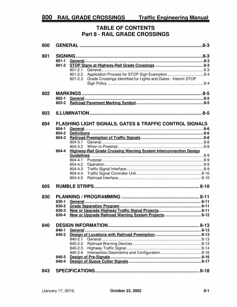
800 RAIL GRADE CROSSINGS Traffic Engineering Manual (January 17, 2014) October 23, 2002 8-1 TABLE OF CONTENTS Part 8 - RAIL GRADE CROSSINGS 800 GENERAL ...............................................................................................8-3 801 SIGNING ..................................................................................................8-3 801-1 General...............................................................................................................8-3 801-2 STOP Signs at Highway-Rail Grade Crossings ........................................... 8-3 801-2.1 General..................... ....................................................................... 8-3 801-2.2 Application Process for STOP Sign Exemption .... .............................8-4 801-2.3 Grade Crossings Identified for Lights and Gates - Interim STOP Sign Policy .......................................................... .............................8-4 802 MARKINGS ............................................................................................ 8-5 802-1 General .......................................................................................................... 8-5 802-2 Railroad Pavement Marking Symbol ............................................................ 8-5 803 ILLUMINATION ...................................................................................... 8-5 804 FLASHING LIGHT SIGNALS, GATES & TRAFFIC CONTROL SIGNALS 804-1 General ........................................................................................... 8-6 804-2 Definitions .................................................................................................... 8-6 804-3 Railroad Preemption of Traffic Signals ........................................................ 8-8 804-3.1 General ........................................................................................... 8-8 804-3.2 When to Preempt ............................................................................ 8-8 804-4 Highway-Rail Grade Crossing Warning System Interconnection Design Guidelines .................................................................................................... 8-9 804-4.1 Purpose .......................................................................................... 8-9 804-4.2 Operation ........................................................................................ 8-9 804-4.3 Traffic Signal Interface..................................................................... 8-9 804-4.4 Traffic Signal Controller Unit .......................................................... 8-10 804-4.5 Railroad Interface .......................................................................... 8-10 805 RUMBLE STRIPS................................................................................. 8-10 830 PLANNING / PROGRAMMING ............................................................ 8-11 830-1 General ........................................................................................................ 8-11 830-2 Grade Separation Program ......................................................................... 8-11 830-3 New or Upgrade Highway Traffic Signal Projects...................................... 8-11 830-4 New or Upgrade Railroad Warning System Projects................................. 8-12 840 DESIGN INFORMATION ...................................................................... 8-13 840-1 General ........................................................................................................ 8-13 840-2 Design of Locations with Railroad Preemption ......................................... 8-13 840-2.1 General ......................................................................................... 8-13 840-2.2 Railroad Warning Devices ............................................................. 8-13 840-2.3 Highway Traffic Signal ................................................................... 8-14 840-2.4 Intersection Geometrics and Configuration .................................... 8-16 840-3 Design of Pre-Signals ................................................................................. 8-16 840-4 Design of Queue Cutter Signals ................................................................. 8-17 843 SPECIFICATIONS ................................................................................ 8-18
Transcript of 800 RAIL GRADE CROSSINGS Traffic Engineering Manual TABLE
800 RAIL GRADE CROSSINGS Traffic Engineering Manual
(January 17, 2014) October 23, 2002 8-1
TABLE OF CONTENTS
Part 8 - RAIL GRADE CROSSINGS 800 GENERAL ...............................................................................................8-3 801 SIGNING ..................................................................................................8-3
801-1 General...............................................................................................................8-3 801-2 STOP Signs at Highway-Rail Grade Crossings ........................................... 8-3
801-2.1 General..................... ....................................................................... 8-3 801-2.2 Application Process for STOP Sign Exemption .... .............................8-4 801-2.3 Grade Crossings Identified for Lights and Gates - Interim STOP Sign Policy .......................................................... .............................8-4
802 MARKINGS ............................................................................................ 8-5
802-1 General .......................................................................................................... 8-5 802-2 Railroad Pavement Marking Symbol ............................................................ 8-5
803 ILLUMINATION ...................................................................................... 8-5 804 FLASHING LIGHT SIGNALS, GATES & TRAFFIC CONTROL SIGNALS 804-1 General ........................................................................................... 8-6
804-2 Definitions .................................................................................................... 8-6 804-3 Railroad Preemption of Traffic Signals ........................................................ 8-8 804-3.1 General ........................................................................................... 8-8 804-3.2 When to Preempt ............................................................................ 8-8 804-4 Highway-Rail Grade Crossing Warning System Interconnection Design
Guidelines .................................................................................................... 8-9 804-4.1 Purpose .......................................................................................... 8-9 804-4.2 Operation ........................................................................................ 8-9 804-4.3 Traffic Signal Interface ..................................................................... 8-9 804-4.4 Traffic Signal Controller Unit .......................................................... 8-10 804-4.5 Railroad Interface .......................................................................... 8-10 805 RUMBLE STRIPS................................................................................. 8-10 830 PLANNING / PROGRAMMING ............................................................ 8-11
830-1 General ........................................................................................................ 8-11 830-2 Grade Separation Program ......................................................................... 8-11 830-3 New or Upgrade Highway Traffic Signal Projects...................................... 8-11 830-4 New or Upgrade Railroad Warning System Projects ................................. 8-12
840 DESIGN INFORMATION ...................................................................... 8-13
840-1 General ........................................................................................................ 8-13 840-2 Design of Locations with Railroad Preemption ......................................... 8-13 840-2.1 General ......................................................................................... 8-13 840-2.2 Railroad Warning Devices ............................................................. 8-13 840-2.3 Highway Traffic Signal ................................................................... 8-14 840-2.4 Intersection Geometrics and Configuration .................................... 8-16 840-3 Design of Pre-Signals ................................................................................. 8-16 840-4 Design of Queue Cutter Signals ................................................................. 8-17
843 SPECIFICATIONS ................................................................................ 8-18

800 RAIL GRADE CROSSINGS Traffic Engineering Manual
8-2 October 23, 2002 (January 17, 2014)
895 REFERENCE RESOURCES ................................................................ 8-19 895-1 Railroad Grade Separation Program Policies and Procedures Manual .... 8-19 895-2 Railroad-Highway Grade Crossing Handbook..............................................8-19
895-3 AREMA Communication & Signal Manual of Recommended Practice ........................................................................................................ 8-19 896 FORMS INDEX ..................................................................................... 8-21 896-1 Highway-Rail Grade Crossing Warning System Railroad Configuration and Timing Requirements ................................................... 8-21 898 FIGURES INDEX .................................................................................. 8-22 898-1 Example of an Interconnection Warning Label .......................................... 8-22

800 RAIL GRADE CROSSINGS Traffic Engineering Manual
Revised January 17, 2014 October 23, 2002 8-3
Part 8 – RAIL GRADE CROSSINGS
800 GENERAL
OMUTCD Part 8 addresses traffic controls at highway-rail grade crossings and highway-light rail grade crossings. Very few, if any routes under ODOT’s jurisdiction involve traffic control at highway-light rail transit (LRT) grade crossings. Part 8 of the Traffic Engineering Manual (TEM) provides additional guidance for use of traffic control devices at these crossings. See TEM Part 4 (Signals) for additional information about traffic controls at rail grade crossings, including Signal Preemption and Warning System Interconnection design guidelines. The FHWA Railroad-Highway Grade Crossing Handbook (see Section 895-2) also provides useful guidance when evaluating and prioritizing improvements to highway-rail grade crossings.
801 SIGNING
801-1 General Signs used at highway-rail grade crossings are addressed in OMUTCD Chapter 8B. 801-2 STOP Signs at Highway-Rail Grade Crossings
801-2.1 General
ORC Section 4511.43 defines the obedience required to a STOP or YIELD sign, and ORC Section 4511.61 addresses the use of STOP and YIELD signs at railroad grade crossings. Effective July 2013, the STOP sign basically became the primary regulatory traffic control device at passive railroad grade crossings. The YIELD sign is used only at selected locations with the approval of the ODOT Director. Also, the highway agency is now responsible for installation of the STOP or YIELD sign. Normally, the STOP sign will be on the same post as the Crossbuck; however, as noted in the OMUTCD, there may be some situations where it has been erected on a separate support. If the STOP sign is posted on railroad property, it will be the Railroad company’s responsibility to maintain it. ODOT and the Ohio Rail Development Commission (ODRC) have established a program to address the statewide changeover of YIELD sign at passive highway-rail grade crossings, to STOP signs. This program will essentially involve the review of every public passive grade crossing in the State. Those for which an exemption is not granted will have STOP signs installed. The goal is to have a list of exemption-eligible crossing compiled by March 1, 2014, and after that date initiate a program to install STOP signs at any crossing not identified and approved by ODOT for an exemption.
Every passive public highway-railroad grade crossing in Ohio is now required to have a Crossbuck sign and either a STOP or YIELD sign at the crossing itself. It is intended that each passive highway-railroad grade crossing in Ohio will be marked with a minimum of the Crossbuck sign and a STOP sign at the crossing, unless a STOP sign exemption (see Section 801-2.2) is requested and granted, as noted in ORC Section 4511.61(C)(2). OMUTCD Sections 8B.04 and 8B.05 provide additional information about the use of STOP signs at railroad and LRT crossings. If a local highway authority (LHA) determines that it wants to install STOP signs at a crossing not on the list of those identified for an exemption and does not want to wait for the statewide

800 RAIL GRADE CROSSINGS Traffic Engineering Manual
8-4 October 23, 2002 Revised January 17, 2014
program, the LHA may do so as long as the installation meets the same installation standards. However, the LHA must also notify ORDC of this action so that the records for the statewide program can be updated. 801-2.2 Application Process for STOP Sign Exemption Except as noted in Subsection 801-2.1 for the interim statewide changeover program, if an LHA desires an exemption from the placement of STOP signs, the LHA shall submit a written request to the District. The District shall review the request and forward it with recommendations to the Office of Traffic Operations (OTO). OTO shall review the STOP sign exemption request with the District and the Ohio Rail Development Commission (ORDC). OTO will make recommendations to the ODOT Director and subsequently notify the LHA of the exemption status. When reviewing the exemption request the following should be considered: 1. The existence and condition of traffic control devices near the crossing, and any potential
conflicts and delays that may occur at nearby locations if a STOP sign is installed at the grade crossing, such as a queue of vehicles backing up into the intersection.
2. Cross-corner sight distances for both approaches to the crossing. Location and type of
visual obstructions (check for permanent and seasonal obstructions). Can the driver adequately detect trains without coming to a stop?
3. Geometrics and approximate relative elevations. 4. Average daily traffic at the crossing (cars and trains). For example, without a compelling
reason, STOP signs should not be used if there is less than one train per day. Also, STOP signs are generally impractical if the ADT is over 4,000 cars per day.
Highway-rail grade crossing locations on ODOT-maintained highways shall be evaluated using this same process and criteria.
801-2.3 Grade Crossings Identified for Lights and Gates – Interim STOP Sign Policy
During the interim changeover program described in Section 801-2.1, when a highway-rail grade crossing has been identified by the Ohio Rail Development Commission (ORDC) or the Public Utilities Commission of Ohio (PUCO) as warranting flashers and gates, temporary STOP signs should be installed at the crossing unless the highway agency involved determines that the STOP signs present more of a hazard to the traveling public than YIELD signs. The same factors noted in Subsection 801-2.2 should be used in evaluating the location.
The ORDC and/or PUCO shall notify the highway agency involved of this interim STOP sign policy at the crossing being upgraded to active warning devices at the diagnostic review. If the highway authority fails to attend the diagnostic review, the ORDC or PUCO shall notify the local authority of the policy in writing following the diagnostic review. Should the highway authority determine that a STOP sign should be installed, they shall instruct the railroad to remove the YIELD sign (if present), and the LHA shall install the STOP signs (and Stop Ahead signs if needed).
When the flasher and gates are installed, the STOP and Stop Ahead signs shall be removed.

800 RAIL GRADE CROSSINGS Traffic Engineering Manual
Revised January 17, 2014 October 23, 2002 8-5
802 MARKINGS
802-1 General The general standards for markings at rail grade crossings are addressed in OMUTCD Chapter 8B and Figures 8B-6 through 8B-9. 802-2 Railroad Pavement Marking Symbol As noted in OMUTCD Figure 8B-6, the highway-rail grade crossing pavement marking symbol consists of the “RXR and two 24-inch wide transverse lines.” However, for contract plan payment purposes, the “railroad symbol marking” is described in CMS Item 641.08 as including the crossbuck, two “R”s, two transverse lines and a stop line. The symbol is also illustrated in SCD TC-71.10. The highway-rail grade crossing alternative (narrow) pavement markings shown in OMUTCD Figure 8B-7 (detail B) should not be used on ODOT-maintained routes unless a narrow roadway makes the standard symbol impractical.
803 ILLUMINATION
When an engineering study determines that better nighttime visibility of the train and the highway-rail grade crossing is needed, illumination at and adjacent to the highway-rail crossing may be installed. Standards and guidelines for highway lighting highway-rail grade crossings are in Part 11 of this Manual.
800 RAIL GRADE CROSSINGS Traffic Engineering Manual
8-6 October 23, 2002 (January 17, 2014)
804 FLASHING LIGHT SIGNALS, GATES & TRAFFIC CONTROL SIGNALS
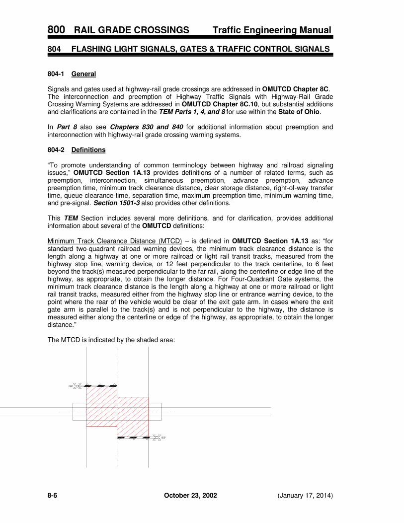
804-1 General Signals and gates used at highway-rail grade crossings are addressed in OMUTCD Chapter 8C. The interconnection and preemption of Highway Traffic Signals with Highway-Rail Grade Crossing Warning Systems are addressed in OMUTCD Chapter 8C.10, but substantial additions and clarifications are contained in the TEM Parts 1, 4, and 8 for use within the State of Ohio. In Part 8 also see Chapters 830 and 840 for additional information about preemption and interconnection with highway-rail grade crossing warning systems. 804-2 Definitions “To promote understanding of common terminology between highway and railroad signaling issues,” OMUTCD Section 1A.13 provides definitions of a number of related terms, such as preemption, interconnection, simultaneous preemption, advance preemption, advance preemption time, minimum track clearance distance, clear storage distance, right-of-way transfer time, queue clearance time, separation time, maximum preemption time, minimum warning time, and pre-signal. Section 1501-3 also provides other definitions. This TEM Section includes several more definitions, and for clarification, provides additional information about several of the OMUTCD definitions: Minimum Track Clearance Distance (MTCD) – is defined in OMUTCD Section 1A.13 as: “for standard two-quadrant railroad warning devices, the minimum track clearance distance is the length along a highway at one or more railroad or light rail transit tracks, measured from the highway stop line, warning device, or 12 feet perpendicular to the track centerline, to 6 feet beyond the track(s) measured perpendicular to the far rail, along the centerline or edge line of the highway, as appropriate, to obtain the longer distance. For Four-Quadrant Gate systems, the minimum track clearance distance is the length along a highway at one or more railroad or light rail transit tracks, measured either from the highway stop line or entrance warning device, to the point where the rear of the vehicle would be clear of the exit gate arm. In cases where the exit gate arm is parallel to the track(s) and is not perpendicular to the highway, the distance is measured either along the centerline or edge of the highway, as appropriate, to obtain the longer distance.” The MTCD is indicated by the shaded area:

800 RAIL GRADE CROSSINGS Traffic Engineering Manual
Revised January 17, 2014 October 23, 2002 8-7
Clear Storage Distance – is defined in OMUTCD Section 1A.13 as: “…the distance available for vehicle storage measured between 6 feet from the rail nearest the intersection to the intersection stop line or the normal stopping point on the highway. At skewed grade crossings and intersections, the 6-foot distance shall be measured perpendicular to the nearest rail either along the center line or edge line of the highway, as appropriate, to obtain the shorter distance. Where exit gates are used, the distance available for vehicle storage is measured from the point where the rear of the vehicle would be clear of the exit gate arm. In cases where the exit gate arm is parallel to the track(s) and is not perpendicular to the highway, the distance is measured either along the centerline or edge line of the highway, as appropriate, to obtain the shorter distance.” The following diagram illustrates this clear storage distance:
Design Vehicle – is defined in OMUTCD Section 1A.13 as “the longest vehicle permitted by statute of the road authority (State or other) on that roadway.” ORC Section 5577.05(C)(6) prescribes the maximum length of combination vehicles as sixty-five feet.
Diagnostic Team – is defined in 23 U.S.C. 646.204(d) as: “a group of knowledgeable representatives of the parties of interest in a railroad-highway crossing or group of crossings.” The diagnostic team includes the highway agency or authority with jurisdiction, the regulatory agency with statutory authority and the railroad. Their charge is to determine the need and selection of traffic control devices at a highway-rail grade crossing in accordance with ORC Sections 4511.61, 4513.40, 4907.47, 4907.471, 4907.476, 4907.48, 4907.49, 4907.52 and 4955.33. Constant Warning Time System – is defined as a type of equipment designed to detect both the motion of a train and the approximate speed of the train in order to predict the arrival of the train at the crossing and to provide a relatively uniform warning time in accordance with a pre-set value. Indicator Panel – is defined as an electrical enclosure, mounted on the traffic signal support, strain pole, or similar location, that provides a visual indication of railroad preemption status.

800 RAIL GRADE CROSSINGS Traffic Engineering Manual
8-8 October 23, 2002 Revised January 17, 2014
Interface Panel – is defined as an electrical device panel located within the traffic signal cabinet that contains all necessary relays, connectors, wires and labels to implement the required interconnection between traffic signal equipment and railroad crossing equipment; this includes devices used to drive the indicator panel. Railroad Dwell Interval – is defined as the component of highway traffic signal preemption that follows the Track Clearance Green Interval for the duration of the train movement through the highway-rail grade crossing. Railroad Warning System – is defined as the active traffic control devices and train detection circuitry installed at a highway-rail grade crossing for the purpose of warning road users of the approach of a train. Track Clearance Green Interval – is defined as one interval of the highway traffic signal preemption sequence when the signal faces which control the movement of motor vehicles through the Clear Storage Distance and the Minimum Track Clearance Distance display CIRCULAR GREEN and GREEN ARROW indications. Train Control Signal – is defined as a signal operated by the railroad that is analogous to a roadway traffic signal. It informs a train operator when to proceed, stop, slow down, etc. 804-3 Railroad Preemption of Traffic Signals 804-3.1 General
Railroad preemption is a special control mode designed to clear motor vehicles from, or prohibit motor vehicles from entering, a portion of the roadway known as the Minimum Track Clearance Distance (MTCD), which crosses over or is in close proximity to railroad tracks or rails. Railroad tracks or rails include those rails operated in semi-exclusive rights-of-way for the use of light rail vehicles or streetcars.
The preemption and interconnection of traffic signals with a railroad warning system requires a systems approach in order to ensure the proper functioning of the individual systems as a combined system. No single standard system of traffic control devices is universally applicable for all highway-rail grade crossings. The need for preemption and its corresponding operation is developed through a diagnostic team which conducts an engineering study to determine the appropriate system. See Section 804-4 for a standardized design guideline to define the requirements of the interconnection between the railroad and traffic signal controller. See Form 896-1 for a standardized form to transmit preemption functional and time requirements to the railroad company.
804-3.2 When to Preempt OMUTCD Section 8C.09, states:
“If a highway-rail grade crossing is equipped with a flashing-light signal system and is located within 200 feet of an intersection or midblock location controlled by a traffic control signal, the traffic control signal should be provided with preemption in accordance with Section 4D.27.” “Coordination with the flashing-light signal system, queue detection, or other alternatives should be considered for traffic control signals located farther than 200 feet from the highway-rail grade crossing. Factors to be considered should include traffic volumes, vehicle mix, vehicle and train approach speeds, frequency of trains, and queue lengths.”

800 RAIL GRADE CROSSINGS Traffic Engineering Manual
Revised January 17, 2014 October 23, 2002 8-9
The distance between the railroad and the adjacent intersection which establishes the need for preemption is 200 feet. The predominant factor to consider when determining whether or not to preempt is the queue length. Field observation of queue length during critical traffic periods can provide guidance. Queue arrival and dissipation studies or capacity analysis may be beneficial in further refining the observed queue lengths. The vehicle usage over the crossing may also form a basis to determine whether to preempt or not. Vehicles which haul hazardous materials, school buses or public transportation vehicles may further influence the decision to preempt at locations which fall just outside the maximum distance and queuing length observations.
804-4 Highway-Rail Grade Crossing Warning System Interconnection Design Guidelines
804-4.1 Purpose
The purpose of this design guideline is to define the required interface between a highway-rail grade crossing warning system and a traffic control signal for the purpose of railroad preemption. It defines the standard interface to provide the operation as specified by the Ohio Rail Development Commission (ORDC) for each interconnected highway-rail grade crossing. Interface hardware specifications are given in ODOT Supplemental Specification (SS) 919. Construction requirements are given in ODOT SS 819.
804-4.2 Operation The interface shall provide the following functions: 1. Advance Preemption. This circuit will notify the traffic signal controller of an approaching
train prior to the operation of the active warning devices. 2. Simultaneous Preemption. This circuit will notify the traffic signal controller of an
approaching train at the point the active warning devices begin their operation. This circuit is commonly known as an “XR” circuit.
3. Island Occupied. This circuit will notify the traffic signal controller of the occupancy of the
island circuit by the train. 4. Gate Down. This circuit will notify the traffic signal controller when the gate(s) controlling
access to the track(s) is lowered to within 5 degrees of horizontal. 5. Gate Up. This circuit will notify the traffic signal controller when all gates at the crossing
are raised. This circuit is commonly known as the “GP” circuit. 6. Traffic Signal Health. This circuit will notify the railroad warning system whenever the
traffic signal has entered conflict flash or the power has failed. 804-4.3 Traffic Signal Interface
The traffic signal controller shall be provided with either a relay based interface, a solid state interface using DC isolator cards, a dedicated railroad preemption interface card, or a serial data interface using the IEEE 1570 protocol. If not specified on the plans, a basic controller unit with a cabinet relay interface shall be provided. The interface shall function as defined in ODOT SS 919.

800 RAIL GRADE CROSSINGS Traffic Engineering Manual
8-10 October 23, 2002 Revised January 17, 2014
804-4.4 Traffic Signal Controller Unit The Office of Traffic Operations (OTO) shall maintain a list of approved traffic signal controllers for Railroad Preemption. Refer to TEM Part 4 for additional controller unit requirements.
804-4.5 Railroad Interface
If requested by the railroad or another agency, consideration will be given to the use of the IEEE 1570 serial data interface in lieu of the relay interface described in SS 919. Final determination as to the use of the IEEE 1570 jointly rests with ORDC and ODOT based on the availability of a traffic signal controller unit which supports the IEEE 1570 interface. If a traffic control signal is located on both sides of the crossing and two independent interconnection circuits are required, the railroad shall supply isolated relay contacts for each interconnection circuit. All functions may share common relays with the exception of “Gate Down.” Additionally, two traffic signal health relays will be required, one for each intersection. If the railroad has determined to provide non-motion sensing circuits such as DC or Style C circuits, then a means should be provided to cancel the operation of the warning devices and corresponding preemption request in the event a train stops within the approach to an interconnected warning system. Either an automatic timing circuit or a cutout and a restart pushbutton switch shall be provided for use by the train crew. Operating rules shall require the crew to operate the cut-out or allow the timing circuit to deactivate the warning devices and preemption operation whenever the train is stopped not occupying the crossing for a period of five minutes or greater. If a cut-out pushbutton switch is provided, its operation shall be canceled by operation of the restart pushbutton switch or the occupancy of the island circuit. A cut-out circuit or automatic timing circuit shall not function if the island is occupied.
805 RUMBLE STRIPS
Rumble strips (see TEM Chapter 1415) may be used as an audible and vibratory warning device at highway-rail grade crossings after all other appropriate standard traffic control devices have been considered.
800 RAIL GRADE CROSSINGS Traffic Engineering Manual
Revised January 17, 2014 October 23, 2002 8-11
830 PLANNING / PROGRAMMING
830-1 General This Chapter is intended to provide planners and designers assistance in the planning phase of a project or work assignment. See TEM Chapter 804 for additional information and guidelines on railroad preemption of traffic signals and interconnection with grade crossing warning systems. 830-2 Grade Separation Program The Railroad Grade Separation Program was developed to mitigate the impacts of increased rail traffic in Ohio. It is governed by a subcommittee of the Transportation Review Advisory Council (TRAC). The subcommittee appointed a technical advisory group (TAG) comprised of representatives from ODOT, ORDC, PUCO, the Ohio Emergency Management Agency (OEMA), FHWA, and the CSX and Norfolk Southern Railroads. This committee prepares the initial feasibility study. This in turn is ranked by the subcommittee of the TRAC for final acceptance. Details of the process are found in the Railroad Grade Separation Program Policies and Procedures Manual (Section 895-1). 830-3 New or Upgrade Highway Traffic Signal Projects When a new or upgrade project for a highway traffic signal is planned and it has been determined that preemption is required, it is of the utmost importance to involve the railroad as quickly as possible. In virtually every case, the implementation of preemption will require additional warning time above the minimum time of twenty seconds required by OMUTCD Section 8C.08 from the railroad. The project planner or designer should coordinate with the ORDC and/or PUCO to establish a diagnostic team inspection at the proposed location (see Section 804-2). Once the diagnostic inspection has been held and the preemption operation and timing requirements have been established, the railroad will be able to provide an estimate of cost for the work required (see Section 804-3 and 804-4). The following items should be considered in the project planning process: 1. The time required for the estimate process may take several months. In many cases, once
the diagnostic team inspection has been completed, the railroad will be required to determine the impact not only at the proposed project location, but also at adjacent crossings. In many cases, the diagnostic team will be required to view the railroad requirements on a “corridor” basis. This may be necessitated based on the number of crossings impacted and the type of train detection circuits already in place.
2. The railroad shall determine the types of circuitry which will operate properly based on the
condition of the track. In certain cases, track conditions or crossing surfaces may create limitations which will prohibit the use of certain train detection systems. This may necessitate the need to provide special design considerations to address proper operation of the train detection system.
3. The cost required to provide the required warning time may greatly exceed the cost of the
traffic signal or roadway project. 4. When facing significant costs to provide the required warning time, changes at the
intersection may play a significant role in reducing project costs. 5. Railroad signal material procurement and construction time may be lengthy. Generally, these
projects must be completed within nine months, but in certain cases, site specific needs create delays outside the control of the railroad which may further add to the time required to complete the project.
800 RAIL GRADE CROSSINGS Traffic Engineering Manual
8-12 October 23, 2002 Revised January 17, 2014
6. Remember that crossing consolidation and closure may be an alternative. 7. Any new traffic signal or upgrade to an existing traffic signal that is or will be interconnected
shall require the installation of a backup power system to maintain operation of the traffic signal during periods of commercial power outage. The backup power supply should have sufficient capacity to assure continued operation of the traffic signal for a minimum period of 2.5 hours.
830-4 New or Upgrade Railroad Warning System Projects When a new or upgrade project for a railroad warning system is planned, the ORDC or PUCO, upon notification of the project, will contact the appropriate roadway authority to schedule a diagnostic team inspection (see Section 804-2). If a new or upgrade project for a railroad warning system is proposed by another government agency or a private developer, the agency or developer must establish contact with the ORDC and PUCO to initiate the diagnostic team inspection. If, during the course of the diagnostic team inspection it is determined that a highway traffic signal may require preemption, a plan will be developed to establish the need for preemption and identify any traffic signal upgrades which may be necessary. Some of the items which will be considered will include the following: 1. What are the capabilities of the existing traffic signal equipment and is it capable of providing
preemption operation in accordance with the requirements of the TEM?
2. Is the current phasing and signal operating plan capable of displaying the track clearance green interval?
3. Are the vehicular signal faces capable of displaying the appropriate indications during the preemption sequence?
4. What provisions exist for pedestrians within the intersection?
5. Are turn prohibitions required during preemption?
6. Does the proposed operation create a “yellow trap” condition during the transition into preemption?
7. Are geometric changes to the intersection necessary or desirable?
8. Should certain pedestrian movements be prohibited?
9. Can U-Turn movements add additional delay to the effective beginning of the track clearance green interval?
See Section 804-3 and 804-4 for additional information about railroad preemption of traffic signals and highway-rail grade crossing warning system interconnection design guidelines, respectively.

800 RAIL GRADE CROSSINGS Traffic Engineering Manual
Revised January 17, 2014 October 23, 2002 8-13
840 DESIGN INFORMATION
840-1 General Design information regarding highway-rail grade crossings is found in the L&D Manual Volume 1, Section 700, and in AASHTO’s A Policy on Geometric Design of Highways and Streets, Chapter 9. For projects involving railroads, it is important to get early coordination with the railroad companies and ORDC. Additional information about the coordination needed when planning new or upgrade highway signal projects and railroad system warning projects is provided in TEM Chapter 830. See Chapter 804 for additional information, including definitions, and guidelines on railroad preemption of traffic signals and interconnection with grade crossing warning systems. 840-2 Design of Locations with Railroad Preemption
840-2.1 General When planning the design of a highway traffic signal which is to be interconnected with and preempted by a railroad warning system, the following items must be addressed and resolved prior to completion of the design. See Chapters 804 and 830 for more information. Also, definitions of some of the terms used here are provided in Section 804-2.
840-2.2 Railroad Warning Devices
The following information is required from the railroad in order to proceed with a railroad warning device project. Ideally, the request for this information should be submitted to the railroad prior to the diagnostic team meeting. Having this information available at the time of the diagnostic team inspection will expedite the data collection process and aid in the process of determining the proper train detection circuitry (see Chapters 804 and 830).
1. The railroad company responsible for the design and maintenance of the railroad warning
system. ORDC can provide this information upon request.
2. The Maximum Authorized Speed (MAS) of trains using the line.
3. Do passenger trains use the line or are there plans to add passenger service to the line?
4. If passenger trains use the line, is there a station stop in place or planned for 3 miles either side of the crossing?
5. Is the line equipped with train control signals?
6. If the answer to the above question is yes, explain how the signal controls are handled? a. Overhead line circuits b. Underground cable c. Coded track d. Data radio
7. Does the line support the installation of constant warning time circuitry?
8. Are there any overlapping grade crossings located within 2 miles either side of the
proposed location?
9. If the answer to the above questions is yes, provide the following information: a. The name and DOT number of each overlapping crossing.
800 RAIL GRADE CROSSINGS Traffic Engineering Manual
8-14 October 23, 2002 (January 17, 2014)
b. The type of train detection circuitry installed at each overlapping crossing. c. The frequencies of all equipment installed at any overlapping crossing. d. The Minimum Warning Time provided for each overlapping crossing.
10. Are there any wayside signals located within 2 miles either side of the proposed location?
11. Are there any control points or interlockings located within 2 miles either side of the
proposed location?
12. If the answer to the above question is yes, identify the following: a. The configuration and signal layout at the interlocking. b. If the interlocking is a railroad crossing at grade, how is the interlocking controlled? c. What is the maximum speed through any diverging routes? d. Are there any pending changes to the control point or interlocking which would
impact this project?
13. Are there any switching moves or unusual operating issues conducted within 2 miles either side of the proposed location?
14. What is the Gate Delay time? The gate delay time is the number of seconds the flashing
lights operate prior to the descent of the gate.
15. What is the Gate Descent time? The gate descent time is the period of time in seconds required for all gates controlling the movement of motor vehicles into the MTCD moving toward the signalized intersection to be fully lowered.
840-2.3 Highway Traffic Signal
The public agency responsible for the design and maintenance of the highway traffic signal must be consulted in order to address and resolve numerous issues regarding the design and operation of the highway traffic signal and the intersection geometrics. The following items should be addressed with the public agency as a part of the preemption planning process. Having this information available prior to the diagnostic team inspection will expedite the process (see Chapters 804 and 830).
1. The proposed phasing for the traffic signal may require modification in order to provide
proper operation during the preemption sequence. The following items must be addressed regarding the traffic signal phasing: a. Are the movements over the track capable of being operated independently of other
movements? If the signal is proposed to operate with concurrent movements crossing the track, separate phases must be provided even though the movements normally occur simultaneously.
b. Are pedestrian movements planned? If so, have pedestrian pushbuttons or other pedestrian detectors been provided for every pedestrian movement?
2. The proposed signal displays for the traffic signal may require special considerations.
The following items must be addressed regarding the traffic signal displays:
a. During the track clearance green interval, a GREEN ARROW shall be displayed to motor vehicles exiting the MTCD. This indication is required even if it is not displayed during the normal or non-preempted sequence.
b. In many cases, the entrance into the track clearance green interval will create a yellow trap condition. Refer to Section 403-8 for additional information regarding yellow trap.
800 RAIL GRADE CROSSINGS Traffic Engineering Manual
Revised January 17, 2014 October 23, 2002 8-15
c. Have provisions been made to address turning movements toward the tracks during
preemption? OMUTCD Section 8B.08 states:
“At a signalized intersection that is located within 200 feet of a highway-rail grade crossing, measured from the edge of the track to the edge of the roadway, where the intersection traffic control signals are preempted by the approach of a train, all existing turning movements toward the highway-rail grade crossing should be prohibited during the signal preemption sequences.”
Engineering judgment is required to determine the appropriate measures to be used to address turning movements toward the tracks. As a general rule, the shorter the CSD, the greater the need to prohibit turning moves toward the tracks during preemption. The intent is to keep the intersection clear of motor vehicles during the preemption sequence.
Turning movements may be prohibited during preemption through the use of illuminated LED “blank-out” signs, additional railroad warning devices, protected only signal displays, or a combination of any of these devices. Any blank-out sign used to establish a turn restriction during railroad preemption should contain the illuminated word TRAIN in 4- inch white letters below the symbol.
d. The use of countdown pedestrian signals shall be evaluated to determine their
operation during the transition into preemption. If the right-of-way transfer time (RWTT) provided does not provide for the full Pedestrian Change interval, then strong consideration should be given to using conventional non-countdown displays or other means to provide notification to pedestrians regarding the approach of the train.
3. Use of Pre-Signals - The design of Pre-Signals is specified in Section 840-3. It should be
noted that pre-signal use may decrease the capacity of the signalized intersection. As a result, careful consideration should be given to the use of pre-signals and the overall impact on the intersection. Improper use of pre-signals may result in driver disregard and a decrease in credibility. The use of pre-signals at a highway-rail grade crossing shall be considered if one or more of the following conditions is satisfied. a. Where the CSD is less than 80 feet and there is little opportunity for a design vehicle
to make a right turn on red due to geometric limitations or infrequent gaps in conflicting traffic.
b. Where frequent numbers of vehicles using the crossing are carrying hazardous materials.
c. On a multi-lane approach where overhead obstructions or other physical constraints limit the number of railroad flashing lights to less than one pair per lane.
4. Use of Queue Cutter Signals - The use of queue cutter signals (see Section 840-4)
should be considered as an alternative to interconnection and preemption where the CSD exceeds 450 feet. A queue cutter signal is installed and located in a manner similar to a pre-signal, but it is not connected to or operated as a part of the signalized intersections. A queue cutter signal requires its own controller and vehicle detection system. The length of the queue determines when the queue cutter signal changes. Its normal state is green. Only when a train approaches or a queue forms approaching the MTCD does the indication change to red. Queue cutter signals and their associated control systems require careful planning and design to assure that appropriate fail safe principles are used. A fail-safe vehicle detector (Reno A&E U-1400 or equivalent) must be used to provide a self-check function to verify proper queue detector operation. This is due to the fact that the queue cutter is the only device which will keep the queue clear of the tracks when a train approaches. A queue cutter signal is interconnected with the railroad

800 RAIL GRADE CROSSINGS Traffic Engineering Manual
8-16 October 23, 2002 (January 17, 2014)
warning system for advance preemption. Queue cutter signals may also be effective in other applications where a downstream restriction creates a queue to form toward the MTCD.
5. The operation and timing of the traffic signal require consideration in order to avoid conflicts with the preemption operation. The following items should be considered:
a. If the traffic signal is proposed to operate in a coordinated system, preempted locations should be designed so as not to utilize pedestrian recall on any phases. In addition, the use of rest in walk should never be implemented.
b. The traffic signal timing information is necessary in order to calculate the preemption time requirements. This information must be available prior to the diagnostic team inspection.
c. In order to properly implement railroad preemption, special functionality is
required in the controller unit and the operating software. Refer to Section 403-10 for additional information regarding the controller unit railroad preemption functionality.
840-2.4 Intersection Geometrics and Configuration
Certain intersection geometrics can have a significant impact on the design and installation of railroad warning devices as well as some of the time required for preemption. The following items should be considered as a part of the geometrics and configuration of the intersection:
1. The length of crosswalks is a key component in determining the right-of-way transfer time
(RWTT). Because the pedestrian change interval is a function of crosswalk length, it can be costly to provide the required period of time. Consideration should be given to the potential use of pedestrian refuge islands or right turn channelization where crosswalks exceed 60 feet in length.
2. The crosswalk parallel and closest to the railroad track is the most critical in the transition to track clearance green. Strong consideration should be given to the elimination of this crosswalk in order to reduce the RWTT.
3. Another factor in determining RWTT is the amount of minimum green time provided
during the transition into track clearance green. The appropriate design and placement of vehicle detection should be provided in order to minimize the need for extended minimum green intervals.
4. The length of the gates used at highway-rail grade crossings is limited to 32 feet. Where
multiple lanes are proposed at a highway-rail grade crossing, consideration should be made to providing center islands in order to permit the installation of a median gate. This will reduce the overall length of a single gate arm.
5. The right turn radius can also have a significant impact on gate arm length. Where a
large radius is required, consideration should be given to the installation of a separate channelized right-turn lane with a separate gate in order to reduce gate arm length.
840-3 Design of Pre-Signals Pre-signals can be used to stop motor vehicles approaching the intersection before such vehicles reach the railroad crossing. Pre-signals are typically considered only when one or more of the conditions listed in Section 840-2.3, item 3, is satisfied. Use of pre-signals for longer clear storage distances must carefully consider the violation of driver expectancy for stopping traffic well in advance of the normal stopping point for the intersection as well as the inherent

800 RAIL GRADE CROSSINGS Traffic Engineering Manual
(January 17, 2014) October 23, 2002 8-17
inefficiency of pre-signal operation. The placement of pre-signals does not replace the need for a proper track clearance green interval. 1. The stop line location must be 40 feet in advance of the pre-signals to comply with OMUTCD
Section 4D.15. Pre-signals can be located upstream or downstream from the railroad crossing. Locating the pre-signals downstream from the crossing (between the crossing and the intersection) should be considered so that the stopping point for the pre-signals is the same as the stopping point for the railroad warning device(s). As a general rule, driver compliance with a downstream pre-signal is greater than driver compliance with an upstream pre-signal. Note that at locations where the angle of the tracks is skewed or more than two tracks exist, the placement of a downstream pre-signal may create a condition where drivers stop on the tracks for the pre-signal. This generally occurs where the stop line to pre-signal face distance is greater than 70 feet. In this case, either an upstream pre-signal should be provided or the pre-signal should be eliminated.
2. The pre-signals and support structures shall be located to maintain visibility of the railroad
flashing lights. In some cases, downstream pre-signals may require the use of horizontally aligned signal heads.
3. As required by OMUTCD Section 8C.09, a STOP HERE ON RED (R10-6) sign shall be
installed near the pre-signal or stop line. 4. Whenever a pre-signal is utilized, one or more NO TURN ON RED (R10-11) sign(s) is/are
required. A pre-signal identifies a separate stopping point on the roadway in advance of the signalized intersection requiring the prohibition of right turn on red.
5. The pre-signal intervals should be progressively timed with the downstream signal intervals to provide adequate time to clear vehicles from the track area and the downstream intersection with each cycle of the normal traffic signal operation. Vehicles that are required to make a mandatory stop at the crossing, such as school buses and vehicles hauling hazardous materials, should be considered when determining the progressive timing to ensure they will not be stopped within the minimum track clearance distance. Vehicle detection for the through phase(s) should be placed on the roadway in advance of the pre-signal. Consideration should be given to installation of vehicle detection within the clear storage distance to extend the pre-signal green clearance interval to prevent vehicles from being trapped within the minimum track clearance distance.
6. Left-turn phasing considerations shall be carefully evaluated when using pre-signals. In many cases the pre-signals will need to include signal faces for the through phase as well as the left- turn phase if leading left-turn phasing is used. The use of a lagging left-turn phase to provide the progressive clearance interval may require that the left turn opposing the track clearance be a protected only left-turn phase in order to prevent a yellow trap condition. As an alternative, the opposing movements may be split.
7. The downstream traffic signal faces at the roadway intersection that controls the same
approach as the pre-signal shall be programmable-visibility heads or louvered as appropriate to prevent vehicles stopped at the railroad crossing stop line from seeing the distant green signal indication during the track clearance interval. The downstream signal heads shall be mounted on rigid supports or tethered to maintain the effectiveness of the programmed visibility or louvers.
840-4 Design of Queue Cutter Signals A queue cutter signal is a traffic signal installed at a highway-rail grade crossing in a manner similar to a pre-signal. A queue cutter signal differs from a pre-signal in that it is not connected to or operated as a part of a downstream signalized intersection. The queue cutter signal is a form of coordination between the railroad warning system and a downstream signalized intersection which operates independently of the intersection. The use of a queue cutter signal is beneficial
800 RAIL GRADE CROSSINGS Traffic Engineering Manual
8-18 October 23, 2002 Revised January 17, 2014
whenever the normal advance preemption time is so lengthy that it is not practical to obtain. Generally, a queue cutter signal is installed where the CSD exceeds 450 feet. It is interconnected with the railroad warning system with a 3 to 5 second advance preemption time. A queue cutter signal consists of the following elements: 1. A “safety critical” vehicle detection system using self-check capabilities shall be used to
activate the queue cutter control system. This system is necessary due to the fact that the queue cutter signal is the only device keeping the MTCD clear of vehicles and the system must be known to be operating at all times.
2. The vehicle detection system shall detect the buildup of a queue of vehicles before the queue reaches the MTCD. This requires placement of the detectors sufficiently far enough downstream from the crossing to detect the lack of a gap, provide for a yellow change interval and permit a design vehicle which has lawfully crossed the stop line (entered at end of yellow) to have adequate room to cross over and clear the MTCD.
3. A queue cutter signal control system shall have battery backup which is capable of operating
for a period of time equal to or greater that the associated railroad warning system. 4. Any fault of the queue cutter system shall result in a flashing red display.
5. The stop line location must be 40 feet in advance of the queue cutter signals to comply with
OMUTCD Section 4D.14. Queue cutter signals can be located upstream or downstream from the railroad crossing. Locating the queue cutter signals downstream from the crossing (between the crossing and the intersection) should be considered so that the stopping point for the queue cutter signals is the same as the stopping point for the railroad warning device(s). As a general rule, driver compliance with a downstream queue cutter signal is greater than driver compliance with an upstream queue cutter signal. Note that at locations where the angle of the tracks is skewed or more than two tracks exist, the placement of a downstream queue cutter signal may create a condition where drivers stop on the tracks for the queue cutter signal. This generally occurs where the stop line to queue cutter signal face distance is greater than 70 feet. In this case, an upstream queue cutter signal should be used.
6. The queue cutter signals and support structures shall be located to maintain visibility of the
railroad flashing lights. In some cases, downstream queue cutter signals may require the use of horizontally aligned signal heads.
7. A STOP HERE ON RED (R10-6) sign shall be installed near the queue cutter signal or stop
line.
843 SPECIFICATIONS
ODOT specifications discussed in this Part of the TEM for furnishing and installing a railroad preemption interface are addressed in Supplemental Specifications 810 and 919.
800 RAIL GRADE CROSSINGS Traffic Engineering Manual
Revised January 17, 2014 October 23, 2002 8-19
895 REFERENCE RESOURCES
895-1 Railroad Grade Separation Program Policies and Procedures Manual The Railroad Grade Separation Program Policies and Procedures Manual provides information on the program history, an overview of the annual process to select projects, the initial feasibility study process, project development activities, and financial and project management 895-2 Railroad-Highway Grade Crossing Handbook The Railroad-Highway Grade Crossing Handbook, published by FHWA, presents guidelines for prioritizing improvements to railroad-highway grade crossings and information on the various types of improvements that can be made to the crossing. The handbook also provides guidelines to determine which crossing improvement is the most cost effective for the site. 895-3 AREMA Communication & Signal Manual The AREMA Communication and Signal Manual of Recommended Practice is a valuable resource to gain additional understanding and insight into the design and operation of railroad warning systems. This publication is available on-line through AREMA (American Railway Engineering and Maintenance-of-Way Association) at http://www.arema.org/.

800 RAIL GRADE CROSSINGS Traffic Engineering Manual
8-20 October 23, 2002 (January 17, 2014)
Intentionally blank.
800 RAIL GRADE CROSSINGS Traffic Engineering Manual
Revised January 17, 2014 October 23, 2002 8-21
896 Forms Index
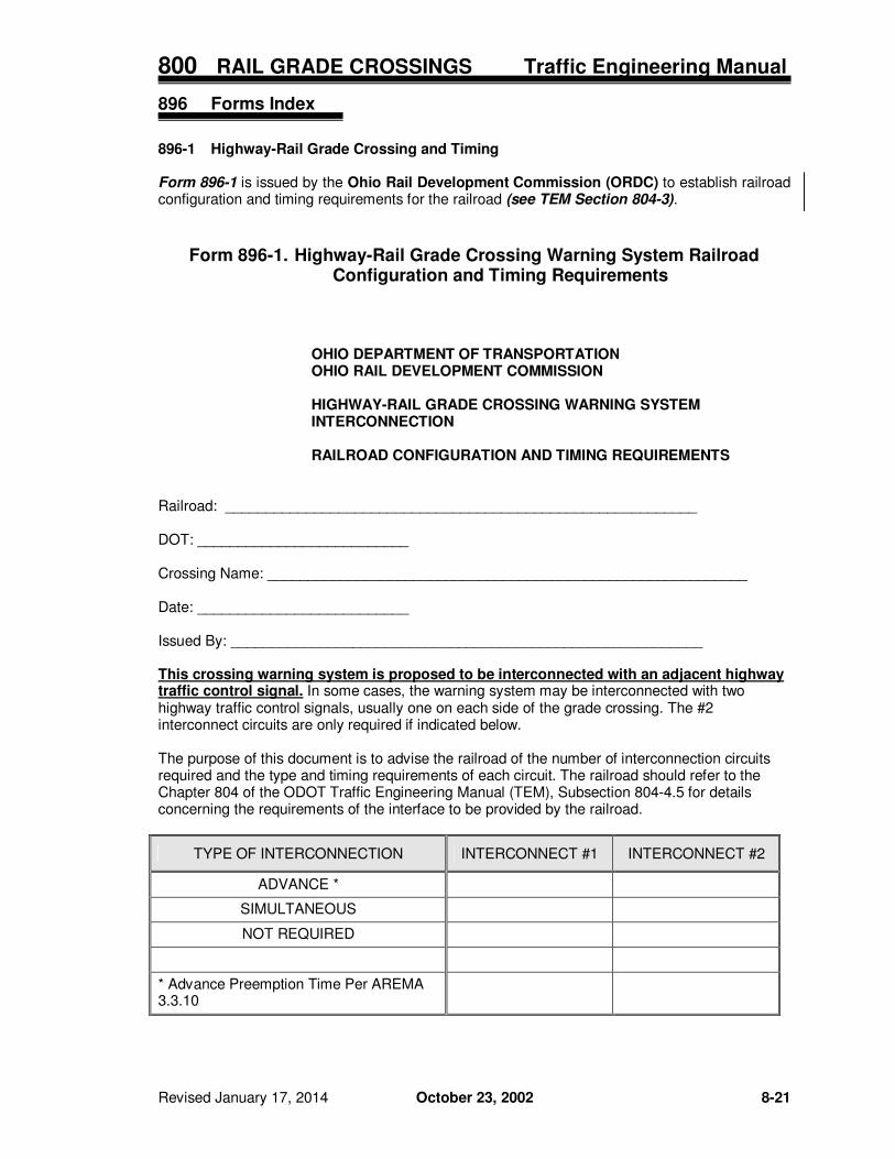
896-1 Highway-Rail Grade Crossing and Timing Form 896-1 is issued by the Ohio Rail Development Commission (ORDC) to establish railroad configuration and timing requirements for the railroad (see TEM Section 804-3).
Form 896-1. Highway-Rail Grade Crossing Warning System Railroad
Configuration and Timing Requirements
OHIO DEPARTMENT OF TRANSPORTATION OHIO RAIL DEVELOPMENT COMMISSION HIGHWAY-RAIL GRADE CROSSING WARNING SYSTEM INTERCONNECTION RAILROAD CONFIGURATION AND TIMING REQUIREMENTS
Railroad: __________________________________________________________ DOT: __________________________ Crossing Name: ___________________________________________________________ Date: __________________________ Issued By: __________________________________________________________ This crossing warning system is proposed to be interconnected with an adjacent highway traffic control signal. In some cases, the warning system may be interconnected with two highway traffic control signals, usually one on each side of the grade crossing. The #2 interconnect circuits are only required if indicated below. The purpose of this document is to advise the railroad of the number of interconnection circuits required and the type and timing requirements of each circuit. The railroad should refer to the Chapter 804 of the ODOT Traffic Engineering Manual (TEM), Subsection 804-4.5 for details concerning the requirements of the interface to be provided by the railroad.
TYPE OF INTERCONNECTION INTERCONNECT #1 INTERCONNECT #2
ADVANCE *
SIMULTANEOUS
NOT REQUIRED
* Advance Preemption Time Per AREMA 3.3.10
800 RAIL GRADE CROSSINGS Traffic Engineering Manual
8-22 October 23, 2002 Revised January 17, 2014
898 Figures Index
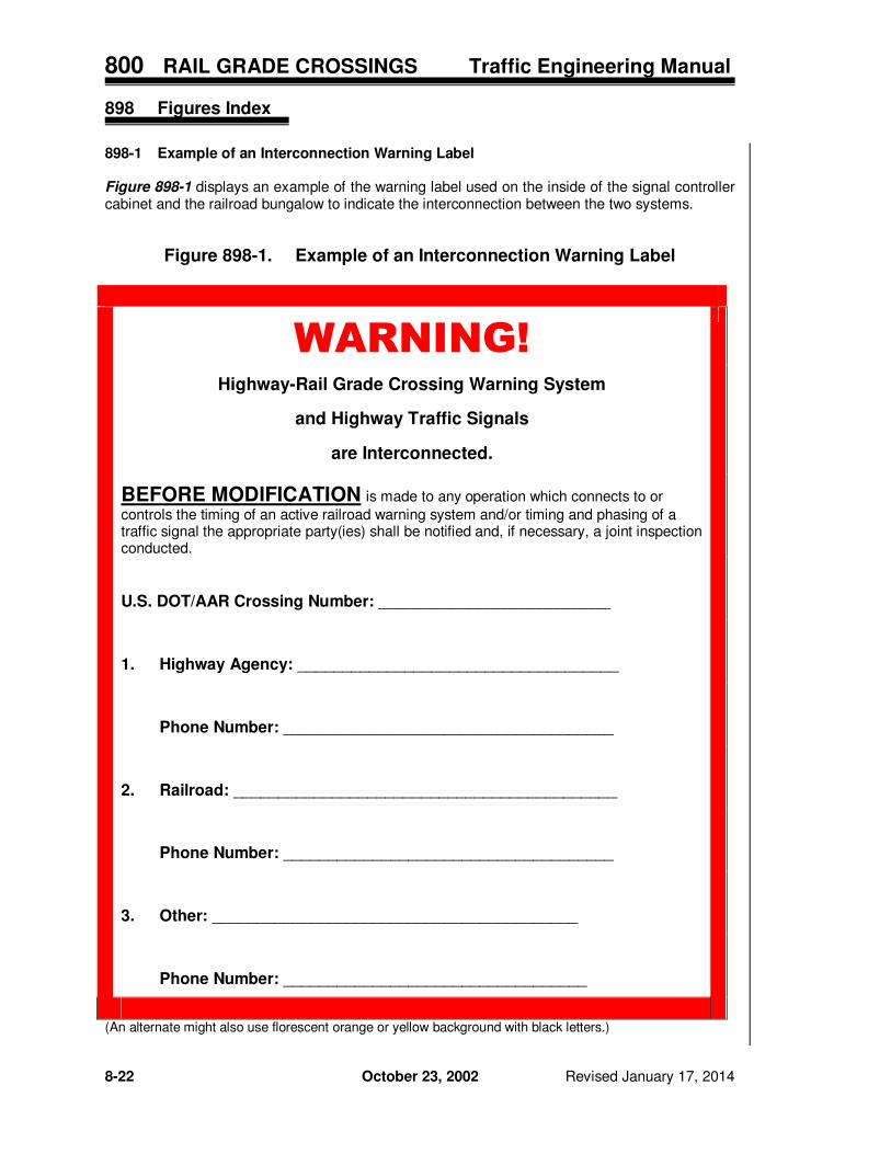
898-1 Example of an Interconnection Warning Label Figure 898-1 displays an example of the warning label used on the inside of the signal controller cabinet and the railroad bungalow to indicate the interconnection between the two systems.
Figure 898-1. Example of an Interconnection Warning Label
WARNING!
Highway-Rail Grade Crossing Warning System
and Highway Traffic Signals
are Interconnected.
BEFORE MODIFICATION is made to any operation which connects to or
controls the timing of an active railroad warning system and/or timing and phasing of a traffic signal the appropriate party(ies) shall be notified and, if necessary, a joint inspection conducted.
U.S. DOT/AAR Crossing Number: __________________________
1. Highway Agency: ____________________________________
Phone Number: _____________________________________
2. Railroad: ___________________________________________
Phone Number: _____________________________________
3. Other: _________________________________________
Phone Number: __________________________________
(An alternate might also use florescent orange or yellow background with black letters.)