Mid-States Highway-Rail Crossing Safety Conference Larry J. Colclasure, P.E.
Part 8. Traffic Controls for Highway-Rail Grade Crossings Page 8TC-1
PART 8. TRAFFIC CONTROLS FOR HIGHWAY-RAIL GRADE CROSSINGS
TABLE OF CONTENTS
PageCHAPTER 8A. GENERAL . . . . . . . . . . . . . . . . . . . . . . . . . . . . . . . . . . . . . . . . . . . 8-1
Section 8A.01 Introduction . . . . . . . . . . . . . . . . . . . . . . . . . . . . . . . . . . . . . . . . . . . . . 8-1Section 8A.02 Use of Standard Devices, Systems, and Practices . . . . . . . . . . . . . . . . 8-3Section 8A.03 Uniform Provisions . . . . . . . . . . . . . . . . . . . . . . . . . . . . . . . . . . . . . . . 8-4Section 8A.04 Highway-Rail Grade Crossing Elimination. . . . . . . . . . . . . . . . . . . . . 8-5Section 8A.05 Temporary Traffic Control Zones . . . . . . . . . . . . . . . . . . . . . . . . . . . . 8-5
CHAPTER 8B. SIGNS AND MARKINGS . . . . . . . . . . . . . . . . . . . . . . . . . . . . . . 8-7
Section 8B.01 Purpose. . . . . . . . . . . . . . . . . . . . . . . . . . . . . . . . . . . . . . . . . . . . . . . . . 8-7Section 8B.02 Highway-Rail Grade Crossing (Crossbuck) Signs (R15-1, R15-2). . . 8-7Section 8B.03 Highway-Rail Grade Crossing Advance Warning Signs
(W10 Series) . . . . . . . . . . . . . . . . . . . . . . . . . . . . . . . . . . . . . . . . . . . 8-10Section 8B.04 EXEMPT Highway-Rail Grade Crossing Signs (R15-3, W10-1a) . . 8-11Section 8B.05 Turn Restrictions During Preemption . . . . . . . . . . . . . . . . . . . . . . . . 8-12Section 8B.06 DO NOT STOP ON TRACKS Sign (R8-8) . . . . . . . . . . . . . . . . . . . 8-13Section 8B.07 STOP (R1-1) or YIELD (R1-2) Signs at Highway-Rail Grade
Crossings . . . . . . . . . . . . . . . . . . . . . . . . . . . . . . . . . . . . . . . . . . . . . . 8-13Section 8B.08 TRACKS OUT OF SERVICE Sign (R8-9). . . . . . . . . . . . . . . . . . . . 8-14Section 8B.09 Emergency Notification Sign (I-13 or I-13a) . . . . . . . . . . . . . . . . . . 8-15Section 8B.10 TRAINS MAY EXCEED 80 MPH Signs (W10-8). . . . . . . . . . . . . . 8-15Section 8B.11 NO TRAIN HORN Sign (W10-9) . . . . . . . . . . . . . . . . . . . . . . . . . . . 8-16Section 8B.12 NO SIGNAL Sign (W10-10). . . . . . . . . . . . . . . . . . . . . . . . . . . . . . . 8-16Section 8B.13 LOOK Sign (R15-8) . . . . . . . . . . . . . . . . . . . . . . . . . . . . . . . . . . . . . 8-16Section 8B.14 Low Ground Clearance Highway-Rail Grade Crossing Sign
(W10-5) . . . . . . . . . . . . . . . . . . . . . . . . . . . . . . . . . . . . . . . . . . . . . . . 8-16Section 8B.15 Storage Space Signs (W10-11, W10-11a, W10-11b) . . . . . . . . . . . . 8-18Section 8B.16 Pavement Markings . . . . . . . . . . . . . . . . . . . . . . . . . . . . . . . . . . . . . . 8-19Section 8B.17 Stop Lines . . . . . . . . . . . . . . . . . . . . . . . . . . . . . . . . . . . . . . . . . . . . . 8-21Section 8B.18 Dynamic Envelope Delineation . . . . . . . . . . . . . . . . . . . . . . . . . . . . . 8-21Section 8B.19 UNEVEN TRACKS Sign (W10-H12) . . . . . . . . . . . . . . . . . . . . . . . 8-21Section 8B.20 Skewed Crossing Sign (W10-H14) . . . . . . . . . . . . . . . . . . . . . . . . . . 8-23
CHAPTER 8C. ILLUMINATION . . . . . . . . . . . . . . . . . . . . . . . . . . . . . . . . . . . . . 8-25
Section 8C.01 Illumination at Highway-Rail Grade Crossings. . . . . . . . . . . . . . . . . 8-25
OMUTCD 2003 Edition (English units are preferred.)

Page 8TC-2 Part 8. Traffic Controls for Highway-Rail Grade Crossings
CHAPTER 8D. FLASHING-LIGHT SIGNALS, GATES, AND TRAFFIC CONTROL SIGNALS . . . . . . . . . . . . . . . . . . . . . . . . . . . . . . . . . 8-27
Section 8D.01 Introduction . . . . . . . . . . . . . . . . . . . . . . . . . . . . . . . . . . . . . . . . . . . . 8-27Section 8D.02 Flashing-Light Signals, Post-Mounted . . . . . . . . . . . . . . . . . . . . . . . 8-29Section 8D.03 Flashing-Light Signals, Overhead Structures . . . . . . . . . . . . . . . . . . 8-31Section 8D.04 Automatic Gates . . . . . . . . . . . . . . . . . . . . . . . . . . . . . . . . . . . . . . . . 8-31Section 8D.05 Four-Quadrant Gate Systems. . . . . . . . . . . . . . . . . . . . . . . . . . . . . . . 8-32Section 8D.06 Train Detection . . . . . . . . . . . . . . . . . . . . . . . . . . . . . . . . . . . . . . . . . 8-35Section 8D.07 Traffic Control Signals at or Near Highway-Rail Grade Crossings . 8-36
FIGURES
Figure 8A-1. Train Dynamic Envelope Delineation . . . . . . . . . . . . . . . . . . . . . . . . . 8-2
Figure 8B-1. Highway-Rail Grade Crossing (Crossbuck) Signs . . . . . . . . . . . . . . . 8-8Figure 8B-2. Typical Placement of Warning Signs and Pavement Markings at
Highway-Rail Grade Crossings . . . . . . . . . . . . . . . . . . . . . . . . . . . . . 8-20Figure 8B-3. Typical Highway-Rail Grade Crossing Pavement Markings . . . . . . 8-22Figure 8B-4. Typical Train Dynamic Envelope Delineation Pavement Markings . 8-23
Figure 8D-1. Composite Drawing of Active Traffic Control Devices for Highway-Rail Grade Crossings Showing Clearances . . . . . . . . . . . . 8-28
Figure 8D-2. Typical Location Plan for Flashing-Light Signals and Four-Quadrant Gates . . . . . . . . . . . . . . . . . . . . . . . . . . . . . . . . . . . . . 8-33
OMUTCD 2003 Edition (English units are preferred.)

Part 8. Traffic Controls for Highway-Rail Grade Crossings Page 8-1
CHAPTER 8A. GENERAL
Section 8A.01 Introduction
Support:
Traffic control for highway-rail grade crossings includes all signs, signals, markings, and other warning devices. It also includes their supports along highways approaching and at highway-rail grade crossings. The function of this traffic control is to permit safe and efficient operation of both rail and highway traffic at highway-rail grade crossings.
For purposes of installation, operation, and maintenance of traffic control devices at highway-rail grade crossings, it is recognized that the crossing of the highway and rail tracks is situated on a right-of-way available for the joint use of both highway traffic and railroad traffic.
In Part 8, the combination of devices selected or installed at a specific highway-rail grade crossing is referred to as a "traffic control system."
Standard:
The traffic control devices, systems, and practices described herein shall be used at all highway-rail grade crossings open to public travel, consistent with Federal, State, and local laws and regulations.
To ensure an understanding of common terminology between highway and railroad signaling issues, the following definitions shall be used:
1. Advance Preemption and Advance Preemption Time—notification of an approaching train is forwarded to the highway traffic signal controller unit or assembly by railroad equipment for a period of time prior to activating the railroad active warning devices. This period of time is the difference in the maximum preemption time required for highway traffic signal operation and the minimum warning time needed for railroad operations and is called the advance preemption time.
2. Cantilevered Signal Structure—a structure that is rigidly attached to a vertical pole and is used to provide overhead support of signal units.
3. Clear Storage Distance—the distance available for vehicle storage measured between 1.8 m (6 ft) from the rail nearest the intersection to the intersection stop line or the normal stopping point on the highway. At skewed highway- rail grade crossings and intersections, the 1.8 m (6 ft) distance shall be
OMUTCD 2003 Edition (English units are preferred.)

Page 8-2 Part 8. Traffic Controls for Highway-Rail Grade Crossings
Measured perpendicular to the nearest rail either along the centerline or edge line of the highway, as appropriate, to obtain the shorter clear distance.
4. Design Vehicle – the longest vehicle permitted by statute of the road authority (State or other) on that roadway. 5. Dynamic Envelope Delineation – the dynamic envelope is the clearance
required for the train and its cargo overhang due to any combination of loading, lateral motion, or suspension failure (see Figure 8A-1).
6. Interconnection – the electrical connection between the railroad active warning
system and the traffic signal controller assembley for the purpose of preemption.
7. Maximum Preemption Time – the maximum amount of time needed following
initiation of the preemption sequence for the highway traffic signals to complete the timing of the right-of-way transfer time, queue clearance time, and separation time.
8. Minimum Track Clearance Distance – for standard two-quadrant railroad
warning devices, the minimum track clearance distance is the length along a highway at one or more railroad tracks, measured either from the highway stop line, warning device, or 3.7 m (12 ft) perpendicular to the track centerline, to 1.8 m (6 ft) beyond the track(s) measured perpendicular to the far rail, along the centerline or edge line of the highway, as approprate, to obtain the longer distance.
Figure 8A-1. Train Dynamic Envelope Delineation
OMUTCD 2003 Edition (English units are preferred.)
Part 8. Traffic Controls for Highway-Rail Grade Crossings Page 8-3
9. Minimum Warning Time—Through Train Movements—the least amount of time active warning devices shall operate prior to the arrival of a train at a highway-rail grade crossing.
10. Monitored Interconnected Operation—an interconnected operation that has the capability to be monitored by the railroad and/or highway authority at a location away from the highway-rail grade crossing.
11. Preemption—the transfer of normal operation of traffic signals to a special control mode.
12. Presignal—supplemental highway traffic signal faces operated as part of the highway intersection traffic signals, located in a position that controls traffic approaching the railroad crossing and intersection.
13. Queue Clearance Time—the time required for the design vehicle stopped within the minimum track clearance distance to start up and move through the minimum track clearance distance. If presignals are present, this time shall be long enough to allow the vehicle to move through the intersection, or to clear the tracks if there is sufficient clear storage distance.
14. Right-of-Way Transfer Time—the maximum amount of time needed for the worst case condition, prior to display of the track clearance green interval. This includes any railroad or traffic signal control equipment time to react to a preemption call, and any traffic signal green, pedestrian walk and clearance, yellow change, and red clearance intervals for conflicting traffic.
15. Separation Time—the component of maximum preemption time during which the minimum track clearance distance is clear of vehicular traffic prior to the arrival of the train.
16. Simultaneous Preemption—notification of an approaching train is forwarded to the highway traffic signal controller unit or assembly and railroad active warning devices at the same time.
Section 8A.02 Use of Standard Devices, Systems, and Practices
Support:
Because of the large number of significant variables to be considered, no single standard system of traffic control devices is universally applicable for all highway-rail grade crossings.
OMUTCD 2003 Edition (English units are preferred.)

Page 8-4 Part 8. Traffic Controls for Highway-Rail Grade Crossings
Guidance:
The appropriate traffic control system should be determined by an engineering study involving both the highway agency and the railroad company.
Option:
The engineering study may include the Highway-Rail Intersection (HRI) components of the National Intelligent Transportation Systems (ITS) architecture, which is a USDOT accepted method for linking the highway, vehicles, and traffic management systems with rail operations and wayside equipment.
Support:
More detail on HRI is available from USDOT’s Federal Railroad Administration, 400 Seventh Street, SW, Washington, DC 20590.
Standard:
Traffic control devices, systems, and practices shall be consistent with the design and application of the standards contained herein.
The highway agency or authority with jurisdiction, the regulatory agencywith statutory authority and the railroad, as applicable, shall determine theneed and selection of devices at a highway-rail grade crossing inaccordance with Sections 4511.61, 4513.40, 4907.47, 4907.471, 4907.48,4907.49, 4907.52 and 4955.33 of the Ohio Revised Code.
Support:
Many other details of highway-rail grade crossing traffic control systems that are not set forth herein are contained in the references listed in Section 1A.11.
Section 8A.03 Uniform Provisions
Standard:
All signs used in highway-rail grade crossing traffic control systems shall be retroreflectorized or illuminated as described in Section 2A.08 to show the same shape and similar color to an approaching road user during both day and night.
No sign or signal shall be located in the center of an undivided highway, except in an island with non-mountable curbs.
OMUTCD 2003 Edition (English units are preferred.)

Part 8. Traffic Controls for Highway-Rail Grade Crossings Page 8-5
Guidance:
Such signs or signals should be installed at least 0.6 m (2 ft) from the face of each curb to the nearest edge of the sign or signal, except as allowed in Section 2A.19.
Where the distance between tracks, measured along the highway between the inside rails, exceeds 30 m (100 ft), additional signs or other appropriate traffic control devices should be used.
Section 8A.04 Highway-Rail Grade Crossing Elimination
Standard:
When a highway-rail grade crossing is eliminated, the traffic control devices for the crossing shall be removed.
The tracks shall also be removed and the space previously occupied by the railbed filled with the same material that comprises the road or highway at thecrossing.
If the existing traffic control devices at a multiple-track highway-rail grade crossing become improperly placed or inaccurate because of the removal of some of the tracks, the existing devices shall be relocated and/or modified.
Guidance:
Any highway-rail grade crossing that cannot be justified should be eliminated.
Where a roadway is removed from a highway-rail grade crossing, the roadway approaches in the railroad right-of-way should also be removed and appropriate signs placed at the roadway end in accordance with Section 3C.04.
Section 8A.05 Temporary Traffic Control Zones
Standard:
Traffic controls for temporary traffic control zones that include highway-rail grade crossings shall be as outlined in Part 6.
When a highway-rail grade crossing exists either within or in the vicinity of a temporary traffic control zone, lane restrictions, flagging, or other operations shall
OMUTCD 2003 Edition (English units are preferred.)

Page 8-6 Part 8. Traffic Controls for Highway-Rail Grade Crossings
not be performed in a manner that would cause vehicles to stop on the railroad tracks, unless a law enforcement officer or flagger is provided at the highway-rail grade crossing to minimize the possibility of vehicles stopping on the tracks, even if automatic warning devices are in place.
Guidance:
Public and private agencies, including emergency services, businesses, and railroad companies, should meet to plan appropriate traffic detours and the necessary signing, marking, and flagging requirements for operations during temporary traffic control zone activities. Consideration should be given to the length of time that the highway-rail grade crossing is to be closed, the type of rail and highway traffic affected, the time of day, and the materials and techniques of repair.
Inconvenience, delay, and crash potential to affected traffic should be minimized. Prior notice should be given to affected public or private agencies, emergency services, businesses, railroad companies, and road users before free movement of vehicles or trains is infringed upon or blocked.
Temporary traffic control zone activities should not extensively prolong the closing of the highway-rail grade crossing. The width and riding quality of the highway surface at a highway-rail grade crossing should, at a minimum, be restored to correspond with the quality of the approaches to the highway-rail grade crossing.
OMUTCD 2003 Edition (English units are preferred.)

Part 8. Traffic Controls for Highway-Rail Grade Crossings Page 8-7
CHAPTER 8B. SIGNS AND MARKINGS
Section 8B.01 Purpose
Support:
Passive traffic control systems, consisting of signs and pavement markings, identify and direct attention to the location of a highway-rail grade crossing and advise drivers, bicyclists, and pedestrians to take appropriate action.
Section 8B.02 Highway-Rail Grade Crossing (Crossbuck) Signs (R15-1, R15-2)
Standard:
As provided in Section 4955.33 of the Ohio Revised Code (see AppendixB2):
At all points where its railroad crosses a public road at a common grade,each company shall erect crossbuck signing at positions at each suchcrossing that are in accordance with the department of transportationmanual for uniform traffic control devices, adopted under section4511.09 of the Revised Code, to give notice of the proximity of therailroad and warn persons to be on the lookout for the locomotive.
Option:
Section 4955.33 of the Ohio Revised Code also provides that:
The director of transportation may erect experimental signs at certain crossings, inlieu of the above required signing, for the purpose of conducting research for thedevelopment of better signing systems.
Standard:
The Highway-Rail Grade Crossing (R15-1) sign, commonly identified as the Crossbuck sign, shall be retroreflectorized white with the words RAILROAD CROSSING in black lettering, mounted as shown in Figure 8B-1.
As a minimum, one Crossbuck sign shall be used on each highway approach to every highway-rail grade crossing, alone or in combination with other traffic control devices.
OMUTCD 2003 Edition (English units are preferred.)

Page 8-8 Part 8. Traffic Controls for Highway-Rail Grade Crossings
Figure 8B-1. Highway-Rail Grade Crossing (Crossbuck) Signs
OMUTCD 2003 Edition (English units are preferred.)

Part 8. Traffic Controls for Highway-Rail Grade Crossings Page 8-9
If automatic gates are not present and if there are two or more tracks at the highway-rail grade crossing, the number of tracks shall be indicated on a supplemental Number of Tracks (R15-2) sign of inverted T shape mounted below the Crossbuck sign in the manner and at the height indicated in Figure 8B-1.
Option:
The supplemental Number of Tracks sign may also be used at highway-rail grade crossings with automatic gates.
Standard:
The Crossbuck sign shall be installed on the right side of the highway on each approach to the highway-rail grade crossing. Where restricted sight distance or unfavorable highway geometry exists on an approach to a highway-rail grade crossing, an additional Crossbuck sign shall be installed on the left side of the highway, possibly placed back-to-back with the Crossbuck sign for the opposite approach, or otherwise located so that two Crossbuck signs are displayed for that approach.
A strip of retroreflective white material not less than 50 mm (2 in) in width shall be used on the back of each blade of each Crossbuck sign for the length of each blade, at all highway-rail grade crossings, except those where Crossbuck signs have been installed back-to-back.
A strip of retroreflective white material, not less than 50 mm (2 in) in width, shall be used on each support at highway-rail grade crossings for the full length of the front and back of the support from the Crossbuck sign or Number of Tracks sign to near ground level.
Guidance:
Crossbuck signs should be located with respect to the highway pavement or shoulder in accordance with the criteria in Chapter 2A and Figures 2A-1 and 2A-2, and should be located with respect to the nearest track in accordance with Figure 8D-2.
The lateral clearance for the nearest edge of the Crossbuck sign should be 1.8 m (6 ft) from the edge of the shoulder, or 3.7 m (12 ft) from the edge of the traveled way in rural areas, and 0.6 m (2 ft) from the face of the curb in urban areas.
Where unusual conditions make variations in location and lateral clearance appropriate, engineering judgment should be used to provide the best practical combination of view and safety clearances.
OMUTCD 2003 Edition (English units are preferred.)

Page 8-10 Part 8. Traffic Controls for Highway-Rail Grade Crossings
Section 8B.03 Highway-Rail Grade Crossing Advance Warning Signs (W10 Series) Standard: A Highway-Rail Grade Crossing Advance Warning (W10-1) sign shall be used on each highway in advance of every highway-rail grade crossing except in the following circumstances:
A. If the distance between the railroad tracks and the parallel highway, from the edge of the track to the edge of the highway, is less than 30 m (100 ft), the W10-2, W10-3, or W10-4 signs shall be used on the parallel highway to warn road users making a turn that they will encounter a highway-rail grade crossing soon after making the turn;
B. On low-volume, low-speed highways crossing minor spurs or other tracks
that are infrequently used and are flagged by train crews;
C. In business districts where active highway-rail grade crossing traffic control devices are in use; and
OMUTCD 2003 Edition (English units are preferred.)

Part 8. Traffic Controls for Highway-Rail Grade Crossings Page 8-11
D. Where physical conditions do not permit even a partially effective display of the sign.
Placement of the Highway-Rail Grade Crossing Advance Warning sign shall be in accordance with Table 2C-4 in Chapter 2C.
Option:
On divided highways and one-way streets, an additional W10-1 sign may be installed on the left side of the roadway.
Standard:
If the W10-2, W10-3, or W10-4 signs are used, sign placement shall be in accordance with Table 2C-4 in Chapter 2C (using the speed of the turning maneuver), and shall be measured from the highway intersection.
Guidance:
If the distance between the railroad tracks and the parallel highway, from the edge of the track to the edge of the roadway, is 30 m (100 ft) or more, a W10-1 sign should be installed in advance of the highway-rail grade crossing, and the W10-2, W10-3, or W10-4 signs should not be used on the parallel highway.
Section 8B.04 EXEMPT Highway-Rail Grade Crossing Signs (R15-3, W10-1a)
Option:
When authorized by the Public Utilities Commission, a supplemental sign (R15-3) with a white background bearing the word EXEMPT may be used below the Crossbuck sign or Number of Tracks sign, if present, at the highway-rail grade crossing, and a supplemental sign (W10-1a) with a yellow background bearing the word EXEMPT may be used below the Highway-Rail Advance Warning sign.
Support:
Section 4511.63 of the Ohio Revised Code (O.R.C.) requires vehicles carrying passengers for hire, school buses carrying students, or vehicles carrying hazardous materials to stop at highway-rail grade crossings. EXEMPT supplemental signs inform drivers of these vehicles that a stop is not required at certain designated highway-rail grade crossings, except when a train, locomotive, or other railroad equipment is approaching or occupying the highway-rail grade crossing.
OMUTCD 2003 Edition (English units are preferred.)

Page 8-12 Part 8. Traffic Controls for Highway-Rail Grade Crossings
Section 8B.05 Turn Restrictions During Preemption Guidance: At a signalized intersection that is located within 60 m (200 ft) of a highway-rail grade crossing, measured from the edge of the track to the edge of the roadway, where the interection traffic control signals are preempted by the approach of a train, all existing turning movements toward the highway-rail grade crossing should be prohibited during the signal preemption sequences. Option: A blank-out or changeable message sign and/or appropriate traffic signal indication or other similar type sign may be used to prohibit turning movements toward the highway-rail grade crossing during preemption.
OMUTCD 2003 Edition (English units are preferred.)
Part 8. Traffic Controls for Highway-Rail Grade Crossings Page 8-13
Standard:
Turn prohibition signs that are associated with preemption shall be visible only when the highway-rail grade crossing restriction is in effect.
Section 8B.06 DO NOT STOP ON TRACKS Sign (R8-8)
Guidance:
Whenever engineering judgment determines that the potential for vehicles stopping on the tracks is high, a DO NOT STOP ON TRACKS (R8-8) sign should be used.
The sign, if used, should be located on the right side of the highway on the near or far side of the highway-rail grade crossing, depending upon which side provides better visibility to approaching drivers.
Option:
DO NOT STOP ON TRACKS signs may be placed on both sides of the track.
On divided highways and one-way streets, a second DO NOT STOP ON TRACKS sign may be placed on the near or far left side of the highway-rail grade crossing to further improve visibility.
Section 8B.07 STOP (R1-1) or YIELD (R1-2) Signs at Highway-Rail GradeCrossings
Option:
As noted in Section 4511.61 of the Ohio Revised Code (see Appendix B2):
The department of transportation and local authorities in their respective jurisdictions,with the approval of the department, may designate dangerous highway crossingsover railroad tracks where on state, county, or township highways on streets or wayswithin municipal corporations, and erect stop signs thereat.
Standard:
In accordance with Section 4511.61 of the Ohio Revised Code, STOPsigns shall be installed at highway-rail grade crossings only with theapproval of the Ohio Department of Transportation.
OMUTCD 2003 Edition (English units are preferred.)

Page 8-14 Part 8. Traffic Controls for Highway-Rail Grade Crossings
Option:
For other highway-rail grade crossings with passive warning devices, YIELD signs may be used based on an engineering study.
Guidance:
The engineering study should take into consideration such factors as highway and train traffic characteristics (including volume and speed), collision history, the need for active control devices, and sight distance to the approaching train.
Option:
If a STOP or YIELD sign is installed at a highway-rail grade crossing, it may be installed on the Crossbuck post or on a separate post at a point where the vehicle is to stop, or as near to that point as practical.
Standard:
For all highway-rail grade crossings where STOP or YIELD signs are installed, the placement shall conform to the requirements of Chapter 2B. Stop Ahead (W3-1a) or Yield Ahead (W3-2a) Advance Warning signs shall also be installed if the criteria for their installation given in Section 2C.26 is met.
Section 8B.08 TRACKS OUT OF SERVICE Sign (R8-9)
Option:
The TRACKS OUT OF SERVICE (R8-9) sign may be used at a highway-rail crossing instead of the Crossbuck signs (R15-1) when the abandonment of the railroad tracks has been approved by the regulatory authority with statutory authority, but only until such time that the tracks are removed and the space previously occupied by the rails filled with the same material that comprises the road or highway at the crossing.
Standard:
When tracks are abandoned, traffic control devices, signal heads and gate arms shall be removed.
The R8-9 sign shall be removed when the tracks have been removed and the space previously occupied by the rail bed filled with the same material that comprises the road or highway at the crossing, or when the highway-rail grade crossing is returned to service.
OMUTCD 2003 Edition (English units are preferred.)

Part 8. Traffic Controls for Highway-Rail Grade Crossings Page 8-15
Section 8B.09 Emergency Notification Sign (I-13 or I-13a) Guidance: An emergency Notification Sign (I-13 or I-13a) should be posted at all highway-rail grade crossings to provide for emergency notification. The sign should have a white message on blue background. Location and placement should be decided cooperatively by the railroad company and the public or private highway agencies based on specific site conditions. However, these signs are typically located on the railroad right-of-way. This sign, which is for emergency notification, should convey a clear and simple message that is visible to anyone stalled or disabled on the railroad tracks, and to anyone with other emergencies. Support: Typical sign messages are shown in the following examples:
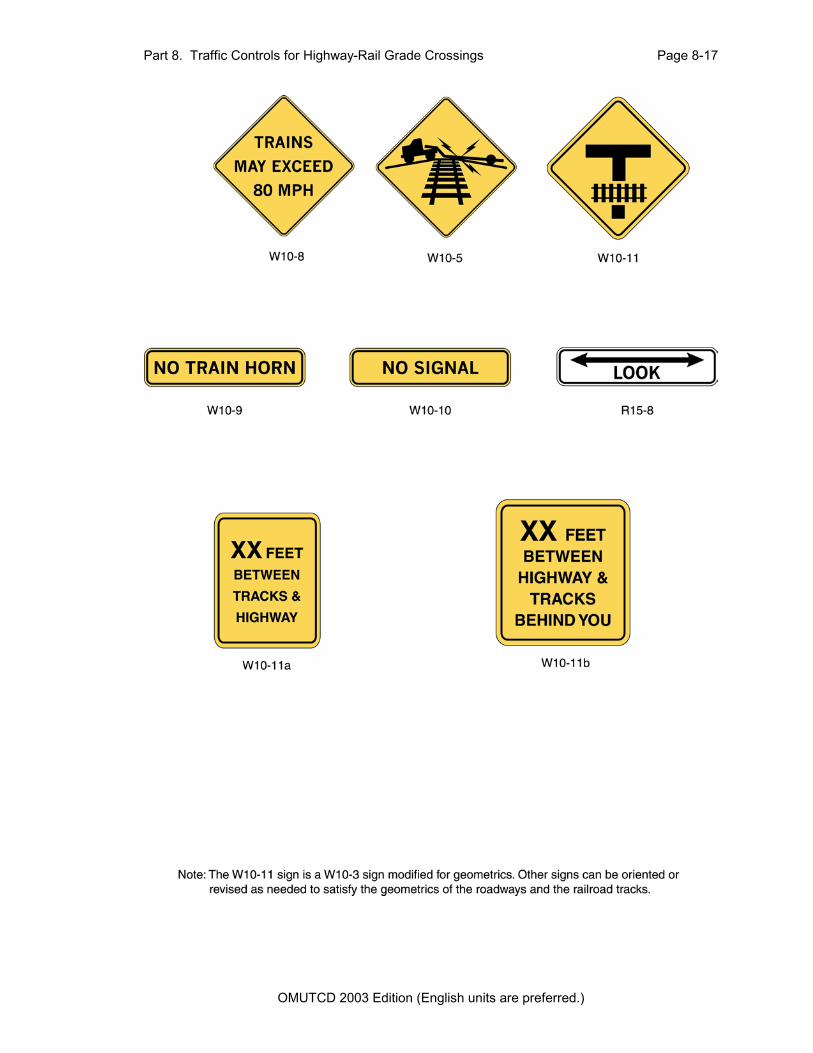
Section 8B.10 TRAINS MAY EXCEED 80 MPH Signs (W10-8) Guidance: Where trains are permitted to travel at speeds exceeding 130 km/h (80 mph), a TRAINS MAY EXCEED 80 MPH (W10-8 ) sign should be installed facing road users approaching the highway-rail grad crossing. If used, the TRAINS MAY EXCEED 80 MPH signs should be posted between the Advance Warning (W10-1) sign and the highway-rail grade crossing on all approaches to the highway-rail grade crossing. The locations should be determined based
OMUTCD 2003 Edition (English units are preferred.)
Page 8-16 Part 8. Traffic Controls for Highway-Rail Grade Crossings
on specific site conditions.
Section 8B.11 NO TRAIN HORN Sign (W10-9)
Standard:
A NO TRAIN HORN (W10-9) sign shall be installed at each highway-rail grade crossing where there is a Federal Railroad Administration authorization for trains to not sound a horn. The sign shall be mounted as a supplemental plaque below the Advance Warning (W10-1) sign.
Section 8B.12 NO SIGNAL Sign (W10-10)
Option:
A NO SIGNAL (W10-10) sign may be installed at highway-rail grade crossings that are not equipped with automated signals.
The NO SIGNAL sign may be mounted as a supplemental plaque below the Advance Warning sign.
Section 8B.13 LOOK Sign (R15-8)
Option:
At highway-rail grade crossings that do not have active warning devices, the LOOK (R15-8) sign may be mounted as a supplemental plaque on the Crossbuck (R15-1) sign post, or as a separate sign in the immediate vicinity of the highway-rail grade crossing on the railroad right-of-way.
Section 8B.14 Low Ground Clearance Highway-Rail Grade Crossing Sign (W10-5)
Guidance:
If the highway profile conditions are sufficiently abrupt to create a hang-up situation for long wheelbase vehicles or for trailers with low ground clearance, the Low Ground Clearance Highway-Rail Grade Crossing (W10-5) sign should be installed in advance of the highway-rail grade crossing.
OMUTCD 2003 Edition (English units are preferred.)
Part 8. Traffic Controls for Highway-Rail Grade Crossings Page 8-17
OMUTCD 2003 Edition (English units are preferred.)
Page 8-18 Part 8. Traffic Controls for Highway-Rail Grade Crossings
Standard:
New warning signs such as this that might not be readily recognizable by the public shall be accompanied by an educational plaque, LOW GROUND CLEARANCE which is to remain in place for at least 3 years after its initial installation (see Chapter 2A).
Guidance:
Auxiliary signs such as AHEAD, NEXT CROSSING, or USE NEXT CROSSING (with appropriate arrows) should be placed at the nearest intersecting highway where a vehicle can detour or at a point on the highway wide enough to permit a U-turn.
If engineering judgment of roadway geometric and operating conditions confirms that vehicle speeds across the railroad tracks should be below the posted speed limit, a W13-1 advisory speed plaque should be posted.
Option:
If the highway-rail grade crossing is rough, word message signs such as BUMP, DIP, or ROUGH CROSSING may be installed. A W13-1 advisory speed plaque may be installed below the word message sign in advance of rough crossings.
Support:
Information on railroad ground clearance requirements is also available in the "American Railway Engineering and Maintenance-of-Way Association’s Engineering Manual," or the American Association of State Highway and Transportation Officials’ "Policy on Geometric Design of Highways and Streets" (see Section 1A.11).
Section 8B.15 Storage Space Signs (W10-11, W10-11a, W10-11b)
Guidance:
A Storage Space (W10-11) sign supplemented by a word message storage distance (W10-11a) sign should be used where there is a highway intersection in close proximity to the highway-rail grade crossing and an engineering study determines that adequate space is not available to store a design vehicle(s) between the highway intersection and the train dynamic envelope.
The Storage Space (W10-11 and W10-11a) signs should be mounted in advance of the highway-rail grade crossing at an appropriate location to advise drivers of the space
OMUTCD 2003 Edition (English units are preferred.)
Part 8. Traffic Controls for Highway-Rail Grade Crossings Page 8-19
available for vehicle storage between the highway intersection and the highway-rail grade crossing.
Option:
The Storage Space sign, W10-11b, may be mounted beyond the highway-rail grade crossing at the highway intersection under the STOP or YIELD sign or just prior to the signalized intersection to remind drivers of the storage space between the tracks and the highway intersection.
Section 8B.16 Pavement Markings
Standard:
All highway-rail grade crossing markings shall be retroreflectorized white. All other markings shall be in accordance with Part 3.
Pavement markings in advance of a highway-rail grade crossing shall consist of an X, the letters RR, a no-passing marking (two-lane highways), and certain transverse lines as shown in Figures 8B-2 and 8B-3.
Identical markings shall be placed in each approach lane on all paved approaches to highway-rail grade crossings where signals or automatic gates are located, and at all other highway-rail grade crossings where the posted or statutory highway speed is 60 km/h (40 mph) or greater.
Pavement markings shall not be required at highway-rail grade crossings where the posted or statutory highway speed is less than 60 km/h (40 mph), or in urban areas, if an engineering study indicates that other installed devices provide suitable warning and control.
Guidance:
When pavement markings are used, a portion of the X symbol should be directly opposite the Advance Warning sign. The X symbol and letters should be elongated to allow for the low angle at which they will be viewed.
Option:
When justified by engineering judgment, supplemental pavement marking symbol(s) may be placed between the Advance Warning sign and the highway-rail grade crossing.
OMUTCD 2003 Edition (English units are preferred.)

Page 8-20 Part 8. Traffic Controls for Highway-Rail Grade Crossings
Figure 8B-2. Typical Placement of Warning Signs and Pavement Markings at Highway-Rail Grade Crossings
OMUTCD 2003 Edition (English units are preferred.)

Part 8. Traffic Controls for Highway-Rail Grade Crossings Page 8-21
Section 8B.17 Stop Lines
Guidance:
The stop line should be a transverse line at a right angle to the traveled way at a point where a vehicle is to stop or as near to that point as possible (4.6 m min to 15 m max (15 ft min to 50 ft max). The stop line should be placed approximately 2.4 m (8 ft) from the gate (if present), but no closer than 4.6 m (15 ft) from the nearest rail.
Section 8B.18 Dynamic Envelope Delineation
Option:
Dynamic envelope markings may be used to mark the edges of the dynamic envelope where there is a highway intersection in close proximity to the highway-rail grade crossing and an engineering study determines that vehicles might stop within the dynamic envelope area.
Standard:
If used, pavement markings for indicating the dynamic envelope shall conform to Part 3 and shall be a 100 mm (4 in) normal solid white line or contrasting pavement color and/or contrasting pavement texture.
Guidance:
If used, dynamic envelope pavement markings should be placed on the highway 1.8 m (6 ft) from the nearest rail, installed parallel to the tracks, unless the operating railroad company advises otherwise. The pavement markings should extend across the roadway as shown in Figure 8B-4.
Section 8B.19 UNEVEN TRACKS Sign (W10-H12)
Guidance:
The UNEVEN TRACKS sign should be used to give warning of a railroadcrossing that is sufficiently uneven or rough as to require a reduction in speed. Itshould be located midway between the Highway-Rail Grade Crossing AdvanceWarning sign (R10-1) and the nearest tracks.
OMUTCD 2003 Edition (English units are preferred.)

Page 8-22 Part 8. Traffic Controls for Highway-Rail Grade Crossings
Figure 8B-3. Typical Highway-Rail Grade Crossing Pavement Markings
OMUTCD 2003 Edition (English units are preferred.)

Part 8. Traffic Controls for Highway-Rail Grade Crossings Page 8-23
Figure 8B-4. Typical Train Dynamic Envelope Delineation Pavement Markings
Option: The UNEVEN TRACKS sign may be supplemented with the Advisiory Speed Plaque (W13-1). Section 8B.20 Skewed Crossing Sign (W10-H14) Option: The Skewed Crossing sign (W10-H14) may be used at a skewed highway-rail grade crossing to warn road users that the railroad tracks are not perpendicular to the highway. Guidance: When the Skewed Crossing sign is used, the tracks symbol should be shown at approximately 45 degrees and in the direction of the crossing (see the “Sign Design Manual” (ODOT).
OMUTCD 2003 Edition (English units are preferred.)
Page 8-24 Part 8. Traffic Controls for Highway-Rail Grade Crossings
Standard:
The Skewed Crossing sign shall not be used as a replacement for therequired Advance Warning (W10-1) sign. If used, the Skewed Crossing signshall supplement the W10-1 sign and shall be mounted on a separate post.
OMUTCD 2003 Edition (English units are preferred.)
Part 8. Traffic Controls for Highway-Rail Grade Crossings Page 8-25
CHAPTER 8C. ILLUMINATION
Section 8C.01 Illumination at Highway-Rail Grade Crossings
Option:
When an engineering study determines that better nighttime visibility of the train and the highway-rail grade crossing is needed (for example, where a substantial amount of railroad operation is conducted at night, where train speeds are low and highway-rail grade crossings are blocked for long periods, or crash history indicates that drivers experience difficulty in seeing trains or traffic control devices during hours of darkness) illumination at and adjacent to the highway-rail grade crossing may be installed.
Support:
Types and location of luminaires for highway-rail grade crossing illumination are contained in the American National Standards Institute’s (ANSI) "Practice for Roadway Lighting RP8" available from the Illuminating Engineering Society (see Section 1A.11).
OMUTCD 2003 Edition (English units are preferred.)

Page 8-26 Part 8. Traffic Controls for Highway-Rail Grade Crossings
OMUTCD 2003 Edition (English units are preferred.)

Part 8. Traffic Controls for Highway-Rail Grade Crossings Page 8-27
CHAPTER 8D. FLASHING-LIGHT SIGNALS, GATES, AND TRAFFIC CONTROL SIGNALS
Section 8D.01 Introduction
Support:
Active traffic control systems inform drivers, bicyclists, and pedestrians of the approach or presence of trains, locomotives, or other railroad equipment at highway-rail grade crossings.
A composite drawing (see Figure 8D-1) shows a post-mounted flashing-light signal (two light units mounted in a horizontal line), a flashing-light signal mounted on an overhead structure, and an automatic gate assembly.
Option:
These systems may be used separately or in combination with each other as determined by an engineering study.
Standard:
The meanings of the flashing-light signals and gates shall be as defined in Sections 4511.62 and 4511.63 of the Ohio Revised Code. Requirements for the erection and operation of the signal equipment, gates, bells and related traffic control devices at railroad grade crossings are contained in Sections 4511.61, 4513.40, 4907.47, 4907.48, 4907.49, 4907.52, 4955.33 and 5589.32 of the Ohio Revised Code (see Appendix B2).
Location and clearance dimensions for flashing-light signals and gates shall be as shown in Figure 8D-1.
When there is a curb, a horizontal clearance of at least 0.6 m (2 ft) shall be provided from the face of the vertical curb to the closest part of the signal or gate arm in its upright position. When a cantilevered-arm flashing-light signal is used, the vertical clearance shall be at least 5.2 m (17 ft) above the crown of the highway to the lowest point of the signal unit.
Where there is a shoulder, but no curb, a horizontal clearance of at least 0.6 m (2 ft) from the edge of a paved or surfaced shoulder shall be provided, with a clearance of at least 1.8 m (6 ft) from the edge of the traveled way.
OMUTCD 2003 Edition (English units are preferred.)

Page 8-28 Part 8. Traffic Controls for Highway-Rail Grade Crossings
Figure 8D-1. Composite Drawing of Active Traffic Control Devices for Highway-Rail Grade Crossings Showing Clearances
OMUTCD 2003 Edition (English units are preferred.)
Part 8. Traffic Controls for Highway-Rail Grade Crossings Page 8-29
Where there is no curb or shoulder, the minimum horizontal clearance shall be 1.8 m (6 ft) from the edge of the traveled way.
Guidance:
Equipment housings (controller cabinets) should have a lateral clearance of at least 9 m (30 ft) from the edge of the highway, and where railroad property and conditions allow, at least 7.6 m (25 ft) from the nearest rail.
If a pedestrian route is provided, sufficient clearance from supports, posts, and gate mechanisms should be maintained for pedestrian travel.
When determined by an engineering study, a lateral escape route to the right of the highway in advance of the highway-rail grade crossing traffic control devices should be kept free of guardrail or other ground obstructions. Where guardrail is not deemed necessary nor appropriate, barriers should not be used for protecting signal supports.
The same lateral clearance and roadside safety features should apply to flashing-light signal and automatic gate locations on both the right and left sides of the roadway.
Option:
In industrial or other areas involving only low-speed highway traffic or where signals are vulnerable to damage by turning truck traffic, guardrail may be installed to provide protection for the signal assembly.
Section 8D.02 Flashing-Light Signals, Post-Mounted
Standard:
The flashing-light signal assembly (shown in Figure 8D-1) on the side of the highway shall include a standard Crossbuck (R15-1) sign, and where there is more than one track, a supplemental Number of Tracks (R15-2) sign, all of which indicate to drivers, bicyclists, and pedestrians the location of a highway-rail grade crossing.
Option:
Bells or other audible warning devices may be included in the assembly and may be operated in conjunction with the flashing lights to provide additional warning for pedestrians and bicyclists.
OMUTCD 2003 Edition (English units are preferred.)
Page 8-30 Part 8. Traffic Controls for Highway-Rail Grade Crossings
Standard:
When indicating the approach or presence of a train, the flashing-light signal shall display toward approaching highway traffic two red lights mounted in a horizontal line flashing alternately.
Flashing-light signals shall be placed to the right of approaching highway traffic on all highway approaches to a highway-rail grade crossing. They shall be located laterally with respect to the highway in conformance with Figure 8D-2 except where such location would adversely affect signal visibility.
At highway-rail grade crossings with highway traffic in both directions, back-to-back pairs of lights shall be placed on each side of the tracks. On multi-lane one-way streets and divided highways, flashing light signals shall be placed on the approach side of the highway-rail grade crossing on both sides of the roadway or shall be placed above the highway.
Each red signal unit in the flashing-light signal shall flash alternately. The number of flashes per minute for each lamp shall be 35 minimum and 65 maximum. Each lamp shall be illuminated approximately the same length of time. Total time of illumination of each pair of lamps shall be the entire operating time. Flashing-light units shall use either 200 mm (8 in) or 300 mm (12 in) nominal diameter lenses.
Guidance:
In choosing between the two sizes of lenses for use in highway-rail grade crossing traffic control signals, consideration should be given to the principles stated in Chapter 4D.
Standard:
Highway-rail grade crossing flashing-light signals shall operate at a low voltage using storage batteries either as a primary or stand-by source of electrical energy. Provision shall be made to provide a source of energy for charging batteries.
Option:
Additional pairs of flashing-light units may be mounted on the same supporting post and directed toward vehicular traffic approaching the highway-rail grade crossing from other than the principal highway route, such as where there are approaching routes on highways closely adjacent to and parallel to the railroad.
OMUTCD 2003 Edition (English units are preferred.)

Part 8. Traffic Controls for Highway-Rail Grade Crossings Page 8-31
Section 8D.03 Flashing-Light Signals, Overhead Structures
Option:
Flashing-light signals may be installed on overhead structures or cantilevered supports as shown in Figure 8D-1 where needed for additional emphasis, or for better visibility to approaching traffic, particularly on multi-lane approaches or highways with profile restrictions.
If it is determined by an engineering study that one set of flashing lights on the cantilever arm is not sufficiently visible to road users, one or more additional sets of flashing lights may be mounted on the supporting post and/or on the cantilever arm.
Standard:
Breakaway or frangible bases shall not be used for overhead structures or cantilevered supports.
Section 8D.04 Automatic Gates
Support:
An automatic gate is a traffic control device used as an adjunct to flashing-light signals.
Standard:
The automatic gate (see Figure 8D-1) shall consist of a drive mechanism and a fully retroreflectorized red- and white-striped gate arm with lights. When in the down position, the gate arm shall extend across the approaching lanes of highway traffic.
In the normal sequence of operation, the flashing-light signals and the lights on the gate arm (in its normal upright position) shall be activated immediately upon detection of the approaching train. The gate arm shall start its downward motion not less than 3 seconds after the flashing-light signals start to operate, shall reach its horizontal position at least 5 seconds before the arrival of the train, and shall remain in the down position as long as the train occupies the highway-rail grade crossing.
When the train clears the highway-rail grade crossing, and if no other train is detected, the gate arm shall ascend to its upright position, following which the flashing lights and the lights on the gate arm shall cease operation.
Gate arms shall be fully retroreflectorized on both sides, have 45-degree diagonal stripes alternately red and white at 400 mm (16 in) intervals measured horizontally,
OMUTCD 2003 Edition (English units are preferred.)

Page 8-32 Part 8. Traffic Controls for Highway-Rail Grade Crossings
and shall have at least three red lights as indicated in Figure 8D-1.
When activated, the gate arm light nearest the tip shall be illuminated continuously and the other lights shall flash alternately in unison with the flashing-light signals.
The approach lane gate arm mechanism shall be designed to fail safe in the down position.
Guidance:
The gate arm should ascend to its upright position in not more than 12 seconds.
In its normal upright position, when no train is approaching or occupying the highway-rail grade crossing, the gate arm should be either vertical or nearly so (see Figure 8D-1).
In the design of individual installations, consideration should be given to timing the operation of the gate arm to accommodate large and/or slow-moving vehicles.
The gates should cover the approaching highway to block all motor vehicles from being driven around the gate without crossing the centerline.
Option:
Automatic gate installations may include median islands between opposing lanes on an approach to a highway-rail grade crossing.
Where gates are located in the median, additional median width may be required to provide the minimum clearance for the counterweight supports.
Section 8D.05 Four-Quadrant Gate Systems
Option:
Four-Quadrant Gate systems may be installed to improve safety at highway-rail grade crossings based on an engineering study when less restrictive measures, such as automatic gates and median islands, are not effective.
Standard:
A Four-Quadrant Gate system shall consist of a series of automatic gates used as an adjunct to flashing-light signals to control traffic on all lanes at the highway-rail grade crossing.
OMUTCD 2003 Edition (English units are preferred.)

Part 8. Traffic Controls for Highway-Rail Grade Crossings Page 8-33
Figure 8D-2. Typical Location Plan for Flashing-Light Signals and Four-Quadrant Gates
OMUTCD 2003 Edition (English units are preferred.)

Page 8-34 Part 8. Traffic Controls for Highway-Rail Grade Crossings
The Four-Quadrant Gate system shall consist of a drive mechanism and fully retroreflectorized red- and white-striped gate arms with lights, and when in the down position the gate arms extend individually across the approaching and exit lanes of highway traffic as shown in Figure 8D-2. Standards contained in Sections 8D.01 through 8D.03 for flashing-light signals shall be followed for signal specifications, location, and clearance distances.
In the normal sequence of operation, the flashing-light signals and the lights on the gate arms (in their normal upright positions) shall be activated immediately upon detection of the approaching train. The gate arms for the approaching lanes of traffic shall start their downward motion not less than 3 seconds after the flashing-light signals start to operate and shall reach their horizontal position at least 5 seconds before the arrival of the train. Exit lane gate arm activation and downward motion shall be based on detection or timing requirements established by an engineering study of the individual site. The gate arms shall remain in the down position as long as the train occupies the highway-rail grade crossing.
When the train clears the highway-rail grade crossing, and if no other train is detected, the gate arms shall ascend to their upright positions, following which the flashing lights and the lights on the gate arms shall cease operation.
Gate arm design, colors, and lighting requirements shall be in accordance with the Standards contained in Section 8D.04.
Except as noted in the Option below, the exit lane gate arm mechanism shall be designed to fail-safe in the up position.
At locations where gate arms are offset a sufficient distance for vehicles to drive between the entrance and exit gate arms, median islands shall be installed in accordance with the needs established by an engineering study.
Guidance:
The gate arms should ascend to their upright position in not more than 12 seconds.
Four-Quadrant Gate systems should only be used in locations with constant-warning- time train detection.
Where an engineering study determines the need, vehicle intrusion detection devices should be installed at the highway-rail grade crossing.
At locations where sufficient space is available, exit gates should be set back from the
OMUTCD 2003 Edition (English units are preferred.)
Part 8. Traffic Controls for Highway-Rail Grade Crossings Page 8-35
track a distance that provides a safe zone long enough to accommodate at least one design vehicle between the exit gate and the nearest rail.
Four-Quadrant Gate systems should include remote health (status) monitoring capable of automatically notifying railroad signal maintenance personnel when anomalies have occurred within the system.
Option:
Exit lane gate arms may fail in the down position if the highway-rail grade crossing is equipped with remote health (status) monitoring.
Four-Quadrant Gate installations may include median islands between opposing lanes on an approach to a highway-rail grade crossing.
Guidance:
Where sufficient space is available, median islands should be at least 18 m (60 ft) in length.
Section 8D.06 Train Detection
Standard:
The devices employed in active traffic control systems shall be actuated by some form of train detection.
Train detection circuits, insofar as practical, shall be designed on the fail-safe principle.
Flashing-light signals shall operate for at least 20 seconds before the arrival of any train, except as noted in the Option below.
Option:
On tracks where all trains operate at less than 32 km/h (20 mph) and where flagging is performed by an employee on the ground, a shorter signal operating time for the flashing-light signals may be used.
Additional warning time may be provided when determined by an engineering study.
OMUTCD 2003 Edition (English units are preferred.)

Page 8-36 Part 8. Traffic Controls for Highway-Rail Grade Crossings
Guidance:
Where the speeds of different trains on a given track vary considerably under normal operation, special devices or circuits should be installed to provide reasonably uniform notice in advance of all train movements over the highway-rail grade crossing. Special control features should be used to eliminate the effects of station stops and switching operations within approach control circuits to prevent excessive activation of the traffic control devices while trains are stopped on or switching upon the approach track control circuits.
Section 8D.07 Traffic Control Signals at or Near Highway-Rail Grade Crossings
Option:
Traffic control signals may be used in lieu of flashing-light signals to control road users at industrial highway-rail grade crossings and other places where train movements are very slow, such as in switching operations.
Standard:
The appropriate provisions of Part 4 relating to traffic control signal design, installation, and operation shall be applicable where traffic control signals are used to control road users in lieu of flashing-light signals at highway-rail grade crossings.
Traffic control signals shall not be used in lieu of flashing-light signals to control road users at a mainline highway-rail grade crossing.
Guidance:
The highway agency with jurisdiction, the regulatory agency with statutory authority, if applicable, and the railroad company should jointly determine the preemption operation at highway-rail grade crossings adjacent to signalized highway intersections.
When a highway-rail grade crossing is equipped with a flashing-light signal system and is located within 60 m (200 ft) of an intersection or mid-block location controlled by a traffic control signal, the traffic control signal should be provided with preemption in accordance with Section 4D.13.
Coordination with the flashing-light signal system should be considered for traffic control signals located farther than 60 m (200 ft) from the highway-rail grade crossing. Factors to be considered should include traffic volumes, vehicle mix, vehicle and train approach speeds, frequency of trains, and queue lengths.
OMUTCD 2003 Edition (English units are preferred.)

Part 8. Traffic Controls for Highway-Rail Grade Crossings Page 8-37
Standard:
If preemption is provided, the normal sequence of traffic control signal indications shall be preempted upon the approach of trains to avoid entrapment of vehicles on the highway-rail grade crossing by conflicting aspects of the traffic control signals and the highway-rail grade crossing flashing-light signals.
This preemption feature shall have an electrical circuit of the closed-circuit principle, or a supervised communication circuit between the control circuits of the highway-rail grade crossing warning system and the traffic control signal controller. The traffic control signal controller preemptor shall be activated via the supervised communication circuit or the electrical circuit that is normally energized by the control circuits of the highway-rail grade crossing warning system. The approach of a train to a highway-rail grade crossing shall de-energize the electrical circuit or activate the supervised communication circuit, which in turn shall activate the traffic control signal controller preemptor. This shall establish and maintain the preemption condition during the time the highway-rail grade crossing warning system is activated, except that when crossing gates exist, the preemption condition shall be maintained until the crossing gates are energized to start their upward movement. When multiple or successive preemptions occur, train activation shall receive first priority.
If a pre-signal is installed at an interconnected highway-rail grade crossing near a signalized intersection, a STOP HERE ON RED (R10-6) sign shall be installed near the pre-signal or at the stop line if used. If there is a nearby signalized intersection with insufficient clear storage distance for a design vehicle, or the highway-rail grade crossing does not have gates, a NO TURN ON RED (R10-11) sign shall be installed for the approach that crosses the railroad track.
Option:
Where highway traffic signals must be located within close proximity to the flashing-light signal system, the highway traffic signals may be mounted on the same overhead structure as the flashing-light signals.
Support:
Section 4D.13 describes additional considerations regarding preemption of traffic control signals at or near highway-rail grade crossings.
OMUTCD 2003 Edition (English units are preferred.)

Page 8-38 Part 8. Traffic Controls for Highway-Rail Grade Crossings
OMUTCD 2003 Edition (English units are preferred.)