80% Two Stage, Variable Speed Category I, Gas Furnace ...
56
Portions of the text and tables are reprinted from NFPA 54 /ANSI Z223.1−2012©, with permission of National Fire Protection Association, Quincy, MA 02269 and American Gas Association, Washing- ton, DC 20001. This reprinted material is not the complete and official position of the NFPA or ANSI, on the referenced subject, which is represented only by the standard in its entirety. Printed in U.S.A. 441 01 2121 02 June 2013 INSTALLATION INSTRUCTIONS 80% Two−Stage, Variable Speed Category I, Gas Furnace F8MVL & G8MVL These instructions must be read and understood completely before attempting installation. Safety Labeling and Signal Words DANGER, WARNING, CAUTION, and NOTE Signal Words in Manuals The signal words DANGER, WARNING, CAUTION, and NOTE are used to identify levels of hazard seriousness. The signal word DANGER is only used on product labels to signify an immediate hazard. The signal words WARNING, CAUTION, and NOTE will be used on product labels and throughout this manual and other manual that may apply to the product. The signal word WARNING is used throughout this manual in the following manner: The signal word CAUTION is used throughout this manual in the following manner: ! WARNING DANGER − Immediate hazards which will result in severe person- al injury or death. WARNING − Hazards or unsafe practices which could result in severe personal injury or death. CAUTION − Hazards or unsafe practices which may result in minor personal injury or product or property damage. NOTE − Used to highlight suggestions which will result in en- hanced installation, reliability, or operation. ! CAUTION Signal Words on Product Labeling Signal words are used in combination with colors and/or pictures or product labels. Safety−alert symbol When you see this symbol on the unit and in instructions or manu- als, be alert to the potential for personal injury. TABLE OF CONTENTS SAFETY CONSIDERATIONS 3 .......................... INTRODUCTION 4 .................................... CODES AND STANDARDS 4 ........................... SAFETY 4 ............................................ GENERAL INSTALLATION 5 ............................ DUCT SYSTEMS 5 .................................... ACOUSTICAL LINING AND FIBROUS GLASS DUCT 5 ..... GAS PIPING AND GAS PIPE PRESSURE TESTING 5 ..... ELECTRICAL CONNECTIONS 5 ........................ VENTING 5 .......................................... ELECTROSTATIC DISCHARGE PRECAUTIONS 5 ......... LOCATION 5 ......................................... AIR FOR COMBUSTION AND VENTILATION 8 ............ INSTALLATION 10 ...................................... DOWNFLOW INSTALLATION 11 ......................... AIR DUCTS 13 ......................................... ELECTRICAL CONNECTIONS 18 ........................ 24−V WIRING 20 ....................................... ACCESSORIES 20 ..................................... VENTING 20 .......................................... CHIMNEY INSPECTION CHART 25 ....................... START−UP, ADJUSTMENT, AND SAFETY CHECK 31 ....... SERVICE AND MAINTENANCE PROCEDURES 42 ......... Use of the AHRI Certified TM Mark indicates a manufacturer’s participation in the program. For verification of certification for individual products, go to www.ahridirectory.org . ! WARNING PERSONAL INJURY, AND/OR PROPERTY DAMAGE HAZARD Failure to carefully read and follow this warning could result in equipment malfunction, property damage, personal injury and/or death. Installation or repairs made by unqualified persons could result in equipment malfunction, property damage, personal injury and/or death. The information contained in this manual is intended for use by a qualified service technician familiar with safety procedures and equipped with proper tools and test instruments. Installation must conform with local building codes and with the Natural Fuel Gas Code (NFCG) NFPA 54/ANSI Z223.1, and National standards of Canada CAN/CSA−B149.1 and .2 Natural Gas and Propane Installation Codes. INSTALLER: Affix these instructions on or adjacent to the furnace. CONSUMER: Retain these instructions for future reference.
Transcript of 80% Two Stage, Variable Speed Category I, Gas Furnace ...

Portions of the text and tables are reprinted from NFPA 54 /ANSI Z223.1−2012©, with permission of National Fire Protection Association, Quincy, MA 02269 and American Gas Association, Washing-ton, DC 20001. This reprinted material is not the complete and official position of the NFPA or ANSI, on the referenced subject, which is represented only by the standard in its entirety.
Printed in U.S.A. 441 01 2121 02 June 2013
INSTALLATION INSTRUCTIONS80% Two−Stage, Variable Speed
Category I, Gas FurnaceF8MVL & G8MVL
These instructions must be read and understood completely before attempting installation.
Safety Labeling and Signal WordsDANGER, WARNING, CAUTION, and NOTE Signal Words in ManualsThe signal words DANGER, WARNING, CAUTION, and NOTEare used to identify levels of hazard seriousness. The signal wordDANGER is only used on product labels to signify an immediatehazard. The signal words WARNING, CAUTION, and NOTE willbe used on product labels and throughout this manual and othermanual that may apply to the product.
The signal word WARNING is used throughout this manual in thefollowing manner:
The signal word CAUTION is used throughout this manual in thefollowing manner:
! WARNING
DANGER − Immediate hazards which will result in severe person-al injury or death.
WARNING − Hazards or unsafe practices which could result insevere personal injury or death.
CAUTION − Hazards or unsafe practices which may result inminor personal injury or product or property damage.
NOTE − Used to highlight suggestions which will result in en-hanced installation, reliability, or operation.
! CAUTIONSignal Words on Product LabelingSignal words are used in combination with colors and/or picturesor product labels.
Safety−alert symbol
When you see this symbol on the unit and in instructions or manu-als, be alert to the potential for personal injury.
TABLE OF CONTENTSSAFETY CONSIDERATIONS 3. . . . . . . . . . . . . . . . . . . . . . . . . .INTRODUCTION 4. . . . . . . . . . . . . . . . . . . . . . . . . . . . . . . . . . . .CODES AND STANDARDS 4. . . . . . . . . . . . . . . . . . . . . . . . . . .SAFETY 4. . . . . . . . . . . . . . . . . . . . . . . . . . . . . . . . . . . . . . . . . . . .GENERAL INSTALLATION 5. . . . . . . . . . . . . . . . . . . . . . . . . . . .DUCT SYSTEMS 5. . . . . . . . . . . . . . . . . . . . . . . . . . . . . . . . . . . .ACOUSTICAL LINING AND FIBROUS GLASS DUCT 5. . . . .GAS PIPING AND GAS PIPE PRESSURE TESTING 5. . . . .ELECTRICAL CONNECTIONS 5. . . . . . . . . . . . . . . . . . . . . . . .VENTING 5. . . . . . . . . . . . . . . . . . . . . . . . . . . . . . . . . . . . . . . . . .ELECTROSTATIC DISCHARGE PRECAUTIONS 5. . . . . . . . .LOCATION 5. . . . . . . . . . . . . . . . . . . . . . . . . . . . . . . . . . . . . . . . .AIR FOR COMBUSTION AND VENTILATION 8. . . . . . . . . . . .INSTALLATION 10. . . . . . . . . . . . . . . . . . . . . . . . . . . . . . . . . . . . . .DOWNFLOW INSTALLATION 11. . . . . . . . . . . . . . . . . . . . . . . . .AIR DUCTS 13. . . . . . . . . . . . . . . . . . . . . . . . . . . . . . . . . . . . . . . . .ELECTRICAL CONNECTIONS 18. . . . . . . . . . . . . . . . . . . . . . . .24−V WIRING 20. . . . . . . . . . . . . . . . . . . . . . . . . . . . . . . . . . . . . . .ACCESSORIES 20. . . . . . . . . . . . . . . . . . . . . . . . . . . . . . . . . . . . .VENTING 20. . . . . . . . . . . . . . . . . . . . . . . . . . . . . . . . . . . . . . . . . .CHIMNEY INSPECTION CHART 25. . . . . . . . . . . . . . . . . . . . . . .START−UP, ADJUSTMENT, AND SAFETY CHECK 31. . . . . . .SERVICE AND MAINTENANCE PROCEDURES 42. . . . . . . . .
Use of the AHRI Certified TM Mark indicates amanufacturer’s participation in the program. Forverification of certification for individual products,go to www.ahridirectory.org .
! WARNINGPERSONAL INJURY, AND/OR PROPERTYDAMAGE HAZARDFailure to carefully read and follow this warning couldresult in equipment malfunction, property damage,personal injury and/or death.Installation or repairs made by unqualified personscould result in equipment malfunction, propertydamage, personal injury and/or death.The information contained in this manual is intended foruse by a qualified service technician familiar with safetyprocedures and equipped with proper tools and testinstruments.Installation must conform with local building codes andwith the Natural Fuel Gas Code (NFCG) NFPA54/ANSI Z223.1, and National standards of CanadaCAN/CSA−B149.1 and .2 Natural Gas and PropaneInstallation Codes.
INSTALLER: Affix these instructions on or adjacent to the furnace.CONSUMER: Retain these instructions for future reference.

2 441 01 2121 02
Figure 1 − Dimensional Drawing
NOTES: 1. Two additional 7/8-in. (22 mm) diameter holes are located in the top plate.2. Minimum return-air openings at furnace, based on metal duct. If flex duct is used, see flex duct manufacturer's recommendations for equivalent diameters.
a. For 800 CFM-16-in. (406 mm) round or 14 1/2 x 12-in. (368 x 305 mm) rectangle. b. For 1200 CFM-20-in. (508 mm) round or 14 1/2 x 19 1/2-in. (368 x 495 mm) rectangle. c. For 1600 CFM-22-in. (559 mm) round or 14 1/2 x 22 1/16-in. (368 x 560mm) rectangle. d. For airflow requirements above 1800 CFM, see Air Delivery table in Product Data literature for specific use of single side inlets. The use of both side inlets, a combination of 1 side and the bottom, or the bottom only will ensure adequate return air openings for airflow requirements above 1800 CFM.
Table 1 – Dimensions − In. (mm)
FURNACE SIZE
A B C E VENTCONNECTIONCABINET
WIDTHIN. (mm)
OUTLETWIDTH
IN. (mm)
TOP AND BOTTOMFLUE COLLAR
IN. (mm)
BOTTOM INLETWIDTH
IN. (mm)
VENTCONNECTION
SIZEIN. (mm)
SHIP WT.LB (KG)
0701412 14−3/16 (360) 12−9/16 (319) 9−5/16 (237) 12−11/16 (322) 4 (102) 115 (52)0901716 17−1/2 (445) 15−7/8 (403) 11−9/16 (294) 16 (406) 4 (102) 130 (59)1102120 21 (533) 19−3/8 (492) 13−5/16 (338) 19−1/2 (495) 4 (102) 155 (70)1352422 24−1/2 (622) 22−7/8 (581) 15−1/16 (383) 23 (584) 4 (102)* 166 (75)
* 135 size furnace require a 5 in. or 6 in. (127 or 152 mm) vent. Use a vent adapter between furnace and vent stack.

3441 01 2121 02
SAFETY CONSIDERATIONS
FIRE, EXPLOSION, ELECTRICAL SHOCK, ANDCARBON MONOXIDE POISONING HAZARD
Failure to follow this warning could result in dangerousoperation, personal injury, death, or property damage.
Improper installation, adjustment, alteration, service,maintenance, or use can cause carbon monoxidepoisoning, explosion, fire, electrical shock, or otherconditions which may cause personal injury orproperty damage. Consult a qualified service agency,local gas supplier, or your distributor or branch forinformation or assistance. The qualified serviceagency must use only factory−authorized and listedkits or accessories when modifying this product.
! WARNING
FURNACE RELIABILITY HAZARD
Failure to follow this caution may result in unitcomponent damage.
Application of this furnace should be indoors withspecial attention given to vent sizing and material,gas input rate, air temperature rise, unit leveling, andunit sizing.
CAUTION!
Installing and servicing heating equipment can be hazardousdue to gas and electrical components. Only trained andqualified personnel should install, repair, or serviceheating equipment. Untrained personnel can perform basicmaintenance functions such as cleaning and replacing airfilters. All other operations must be performed by trainedservice personnel. When working on heating equipment,observe precautions in literature, on tags, and on labelsattached to or shipped with furnace and other safetyprecautions that may apply.These instructions cover minimum requirements and conformto existing national standards and safety codes. In someinstances, these instructions exceed certain local codes andordinances, especially those that may not have kept up withchanging residential construction practices. We require theseinstructions as a minimum for a safe installation.
CUT HAZARD
Failure to follow this caution may result in personalinjury.
Sheet metal parts may have sharp edges or burrs.Use care and wear appropriate protective clothing,safety glasses and gloves when handling parts, andservicing furnaces.
CAUTION!
Wear safety glasses, protective clothing and work gloves.Have fire extinguisher available during start−up andadjustment procedures and service calls.
This is the safety−alert symbol . When you see thissymbol on the furnace and in instructions or manuals, be alertto the potential for personal injury.Understand the signal words DANGER, WARNING, andCAUTION. These words are used with the safety−alert
symbol. DANGER identifies the most serious hazards whichwill result in severe personal injury or death. WARNINGsignifies a hazard which could result in personal injury ordeath. CAUTION is used to identify hazards which may resultin minor personal injury or product and property damage.NOTE is used to highlight suggestions which will result inenhanced installation, reliability, or operation.
Use only with type of gas approved for this furnace. Refer to thefurnace rating plate.
Install this furnace only in a location and position as specified inthe “Location” section of these instructions.
Provide adequate combustion and ventilation air to the furnacespace as specified in “Air for Combustion and Ventila-tion” section.
Combustion products must be discharged outdoors. Connectthis furnace to an approved vent system only, as spe-cified in the “Venting” section of these instructions.
Never test for gas leaks with an open flame. Use a commerciallyavailable soap solution made specifically for the detec-tion of leaks to check all connections, as specified inthe “Gas Piping” section.
Always install furnace to operate within the furnace’s intendedtemperature−rise range with a duct system which hasan external static pressure within the allowable range,as specified in the “Start−Up, Adjustments, and SafetyCheck” section. See furnace rating plate.
When a furnace is installed so that supply ducts carry air circu-lated by the furnace to areas outside the space con-taining the furnace, the return air shall also be handledby duct(s) sealed to the furnace casing and terminatingoutside the space containing the furnace. See “AirDucts” section.
A gas−fired furnace for installation in a residential garage mustbe installed as specified in the warning box in the “Loc-ation” section.
The furnace may be used for construction heat provided that thefurnace installation and operation complies with the firstCAUTION in the LOCATION section of these instruc-tions.
These Multipoise Gas−Fired Furnaces are CSA (formerly A.G.A.and C.G.A.) design−certified for use with natural andpropane gases (see furnace rating plate) and for in-stallation in alcoves, attics, basements, closets, utilityrooms, crawlspaces, and garages. The furnace is fact-ory−shipped for use with natural gas. A CSA (A.G.A.and C.G.A.) listed accessory gas conversion kit is re-quired to convert furnace for use with propane gas.
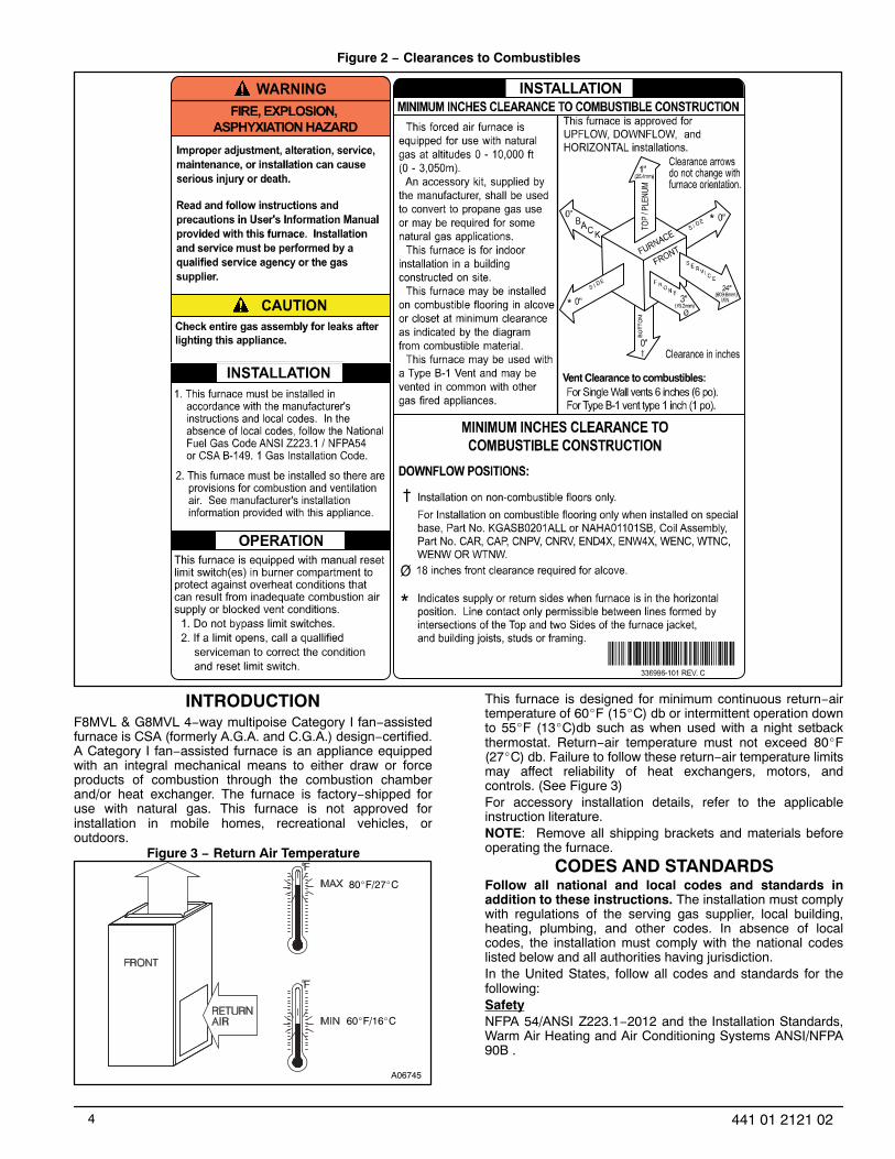
See Figure 2 for required clearances to combustible construc-tion.
Maintain a 1−in. (25 mm) clearance from combustible materialsto supply air ductwork for a distance of 36 in. (914 mm)horizontally from the furnace. See NFPA 90B or localcode for further requirements.
These furnaces SHALL NOT be installed directly on carpeting,tile, or any other combustible material other than woodflooring. In downflow installations, factory accessoryfloor base MUST be used when installed on combust-ible materials and wood flooring. Special base is not re-quired when this furnace is installed on manufacturer’scoil model numbers END4X, ENW4X or coil casingmodel number NAEA. See Figure 2 for clearance tocombustible construction information.
4 441 01 2121 02
Figure 2 − Clearances to Combustibles
INTRODUCTIONF8MVL & G8MVL 4−way multipoise Category I fan−assistedfurnace is CSA (formerly A.G.A. and C.G.A.) design−certified.A Category I fan−assisted furnace is an appliance equippedwith an integral mechanical means to either draw or forceproducts of combustion through the combustion chamberand/or heat exchanger. The furnace is factory−shipped foruse with natural gas. This furnace is not approved forinstallation in mobile homes, recreational vehicles, oroutdoors.
Figure 3 − Return Air Temperature
A06745
80�F/27�C
60�F/16�C
This furnace is designed for minimum continuous return−airtemperature of 60�F (15�C) db or intermittent operation downto 55�F (13�C)db such as when used with a night setbackthermostat. Return−air temperature must not exceed 80�F(27�C) db. Failure to follow these return−air temperature limitsmay affect reliability of heat exchangers, motors, andcontrols. (See Figure 3)For accessory installation details, refer to the applicableinstruction literature.NOTE: Remove all shipping brackets and materials beforeoperating the furnace.
CODES AND STANDARDSFollow all national and local codes and standards inaddition to these instructions. The installation must complywith regulations of the serving gas supplier, local building,heating, plumbing, and other codes. In absence of localcodes, the installation must comply with the national codeslisted below and all authorities having jurisdiction.In the United States, follow all codes and standards for thefollowing:SafetyNFPA 54/ANSI Z223.1−2012 and the Installation Standards,Warm Air Heating and Air Conditioning Systems ANSI/NFPA90B .

5441 01 2121 02
General InstallationCurrent edition of the NFGC and the NFPA 90B. For copies,contact the National Fire Protection Association Inc.,Batterymarch Park, Quincy, MA 02269; (www.NFPA.org) orfor only the NFGC, contact the American Gas Association,400 N. Capitol Street, N.W., Washington, DC 20001(www.AGA.org) .Combustion and Ventilation AirSection 9.3 NFPA 54/ANSI Z223.1−2012 , Air for Combustionand Ventilation .Duct SystemsAir Conditioning Contractors Association (ACCA) Manual D,Sheet Metal and Air Conditioning Contractors NationalAssociation (SMACNA), or American Society of Heating,Refrigeration, and Air Conditioning Engineers (ASHRAE)2001 Fundamentals Handbook Chapter 34 or 2000 HVACSystems and Equipment Handbook Chapters 9 and 16.Acoustical Lining and Fibrous Glass DuctCurrent edition of SMACNA and NFPA 90B as tested by ULStandard 181 for Class I Rigid Air DuctsGas Piping and Gas Pipe Pressure TestingNFPA 54/ANSI Z223.1−2012 ; chapters 5, 6, and 7 andNational Plumbing Codes .Electrical ConnectionsNational Electrical Code (NEC) ANSI/NFPA70−2011 .VentingNFPA 54/ANSI Z223.1−2012; chapters 12 and 13.
ELECTROSTATIC DISCHARGE (ESD)PRECAUTIONS PROCEDURE
FURNACE RELIABILITY HAZARD
Failure to follow this caution may result in unit componentdamage.
Electrostatic discharge can affect electronic components.Take precautions during furnace installation andservicing to protect the furnace electronic control.Precautions will prevent electrostatic discharges frompersonnel and hand tools which are held during theprocedure. These precautions will help to avoid exposingthe control to electrostatic discharge by putting thefurnace, the control, and the person at the sameelectrostatic potential.
CAUTION!
Disconnect all power to the furnace. Multiple disconnects maybe required. DO NOT TOUCH THE CONTROL ORANY WIRE CONNECTED TO THE CONTROL PRIORTO DISCHARGING YOUR BODY’S ELECTROSTATICCHARGE TO GROUND.
Firmly touch the clean, unpainted, metal surface of the furnacechassis which is close to the control. Tools held in aperson’s hand during grounding will be satisfactorilydischarged.
After touching the chassis, you may proceed to service the con-trol or connecting wires as long as you do nothing torecharge your body with static electricity (for example;DO NOT move or shuffle your feet, do not touch un-grounded objects, etc.).
If you touch ungrounded objects (and recharge your body withstatic electricity), firmly touch a clean, unpainted metalsurface of the furnace again before touching control orwires.
Use this procedure for installed and uninstalled (ungrounded)furnaces.
Before removing a new control from its container, discharge yourbody’s electrostatic charge to ground to protect thecontrol from damage. If the control is to be installed in afurnace, follow items 1 through 4 before bringing thecontrol or yourself in contact with the furnace. Put allused and new controls into containers before touchingungrounded objects.
An ESD service kit (available from commercial sources) mayalso be used to prevent ESD damage.
LOCATIONGENERALThis multipoise furnace is shipped in packaged configuration.Some assembly and modifications are required when used inany of the four applications shown in Figure 4.
NOTE: For high−altitude installations, the high−altitudeconversion kit MUST be installed at or above 5500 ft. (1676M) above sea level. Obtain high−altitude conversion kit fromyour area authorized distributor.
Figure 4 − Multipoise Orientations
THE BLOWER IS LOCATEDTO THE RIGHT OF THE
BURNER SECTION, ANDAIR CONDITIONED AIR IS
DISCHARGED TO THE LEFT.
THE BLOWER ISLOCATED BELOW THE
BURNER SECTION, ANDCONDITIONED AIR IS
DISCHARGED UPWARD.
THE BLOWER ISLOCATED ABOVE THE
BURNER SECTION, ANDCONDITIONED AIR IS
DISCHARGED DOWNWARD
THE BLOWER ISLOCATED TO THE LEFT
OF THE BURNER SECTION,AND CONDITIONED AIR IS
DISCHARGED TO THE RIGHT.
A02097

6 441 01 2121 02
This furnace must:
� be installed so the electrical components are protec-ted from water.
� not be installed directly on any combustible materialother than wood flooring for upflow applications.Downflow installations require use of a factory−ap-proved floor base or coil model numbers END4X,ENW4X or coil casing model number NAEA wheninstalled on combustible materials or wood flooring(refer to SAFETY CONSIDERATIONS).
� be located close to the chimney or vent and at-tached to an air distribution system. Refer to AirDucts section.
� be provided ample space for servicing and cleaning.Always comply with minimum fire protection clear-ances shown on the furnace clearance to combust-ible construction label.
The following types of furnace installations may requireOUTDOOR AIR for combustion due to chemical exposures:
� Commercial buildings
� Buildings with indoor pools
� Laundry rooms
� Hobby or craft rooms, and
� Chemical storage areas
If air is exposed to the following substances, it should not beused for combustion air, and outdoor air may be required forcombustion:
� Permanent wave solutions
� Chlorinated waxes and cleaners
� Chlorine based swimming pool chemicals
� Water softening chemicals
� De−icing salts or chemicals
� Carbon tetrachloride
� Halogen type refrigerants
� Cleaning solvents (such as perchloroethylene)
� Printing inks, paint removers, varnishes, etc.
� Hydrochloric acid
� Cements and glues
� Antistatic fabric softeners for clothes dryers
� Masonry acid washing materials
All fuel−burning equipment must be supplied with air for fuelcombustion. Sufficient air must be provided to avoid negativepressure in the equipment room or space. A positive sealmust be made between the furnace cabinet and thereturn−air duct to prevent pulling air from the burner area andfrom draft safeguard opening.
FIRE, INJURY OR DEATH HAZARD
Failure to follow this warning could result in personalinjury, death and/or property damage.
When the furnace is installed in a residential garage, theburners and ignition sources must be located at least 18in. (457 mm) above the floor. The furnace must belocated or protected to avoid damage by vehicles. Whenthe furnace is installed in a public garage, airplanehangar, or other building having a hazardousatmosphere, the furnace must be installed inaccordance with the NFPA 54/ANSI Z223.1−2012 . (SeeFigure 5)
! WARNING
Figure 5 − Installation in a Garage
18−IN. (457.2 mm)MINIMUM TO BURNERS
A93044
FIRE HAZARD
Failure to follow this warning could result in personalinjury, death and/or property damage.
Do not install the furnace on its back or hang furnacewith control compartment facing downward. Safetycontrol operation will be adversely affected. Neverconnect return−air ducts to the back of the furnace.(See Figure 6)
! WARNING
LOCATION RELATIVE TO COOLING EQUIPMENTThe cooling coil must be installed parallel with, or on thedownstream side of the unit to avoid condensation in the heatexchangers. When installed parallel with the furnace,dampers or other flow control must prevent chilled air fromentering the furnace. If the dampers are manually operated,they must be equipped with means to prevent operation ofeither unit unless the damper is in the full−heat or full−coolposition.

7441 01 2121 02
PERSONAL INJURY AND/OR PROPERTYDAMAGE HAZARD
Improper use or installation of this furnace may result inpremature furnace component failure. This gas furnacemay be used for heating buildings under constructionprovided that:
−The furnace is permanently installed with all electricalwiring, piping, venting and ducting installed according tothese installation instructions. A return air duct isprovided, sealed to the furnace casing, and terminatedoutside the space containing the furnace. This prevents anegative pressure condition as created by the circulatingair blower, causing a flame rollout and/or drawingcombustion products into the structure.
−The furnace is controlled by a thermostat. It may not be“hot wired” to provide heat continuously to the structurewithout thermostatic control.
−Clean outside air is provided for combustion. This is tominimize the corrosive effects of adhesives, sealers andother construction materials. It also prevents theentrainment of drywall dust into combustion air, which cancause fouling and plugging of furnace components.
−The temperature of the return air to the furnace ismaintained between 55�F (13�C) and 80�F (27�C), withno evening setback or shutdown. The use of the furnacewhile the structure is under construction is deemed to beintermittent operation per our installation instructions.
−The air temperature rise is within the rated rise range onthe furnace rating plate, and the gas input rate has beenset to the nameplate value. −The filters used to clean thecirculating air during the construction process must beeither changed or thoroughly cleaned prior to occupancy.
−The furnace, ductwork and filters are cleaned asnecessary to remove drywall dust and construction debrisfrom all HVAC system components after construction iscompleted.
−Verify proper furnace operating conditions includingignition, gas input rate, air temperature rise, and ventingaccording to these installation instructions.
CAUTION!Figure 6 − Prohibit Installation on Back
A02054
Table 2 – Minimum Free Area Required for Each Combustion Air opening of Duct to Outdoors
FURNACEINPUT(BTUH)
TWO HORIZONTAL DUCTS SINGLE DUCT OR OPENING TWO OPENINGS OR VERTICAL DUCTS(1 SQ. IN./2,000 BTUH) (1,100 SQ. MM/KW) (1 SQ. IN./3,000 BTUH) (734 SQ. MM/KW) (1 SQ. IN./4,000 BTUH) (550 SQ. MM/KW)Free Area of Opening
and DuctSq. In. (Sq. mm)
Round DuctDia.
In. (mm)
Free Area of Openingand Duct
Sq. In. (Sq. mm)
Round DuctDia.
In. (mm)
Free Area of Openingand Duct
Sq. In. (Sq. mm)
Round DuctDia.
In. (mm)44,000 22 (14194) 6 (152) 14.7 (9484) 5 (127) 11 (7096) 4 (102)66,000 33 (21290) 7 (178) 22 (14193) 6 (152) 16.5 (10645) 5 (127)88,000 44 (28387) 8 (203) 29.3 (18903) 7 (178) 22 (14193) 6 (152)110,000 55 (35484) 9 (229) 36.7 (23677) 7 (178) 27.5 (17742) 6 (152)132,000 66 (42580) 10 (254) 44 (28387) 8 (203) 33 (21290) 7 (178)
EXAMPLES: Determining Free AreaFURNACE WATER HEATER TOTAL INPUT
110,000 + 30,000 = (140,000 divided by 4,000) = 35.0 Sq. In. for each two Vertical Ducts or Openings
66,000 + 40,000 = (106,000 divided by 3,000) = 35.3 Sq. In. for a Single Duct or Opening
88,000 + 30,000 = (118,000 divided by 2,000) = 59.0 Sq. In. for each of two Horizontal Ducts
8 441 01 2121 02
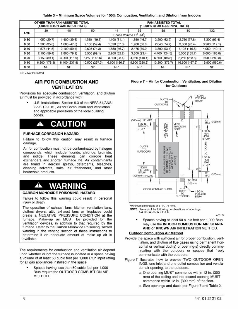
Table 3 – Minimum Space Volumes for 100% Combustion, Ventilation, and Dilution from Indoors
OTHER THAN FAN‐ASSISTED TOTAL (1,000'S BTUH GAS INPUT RATE)
FAN‐ASSISTED TOTAL (1,000'S BTUH GAS INPUT RATE)
ACH30 40 50 44 66 88 110 132
Space Volume Ft3 (M3)0.60 1,050 (29.7) 1,400 (39.6) 1,750 (49.5) 1,100 (31.1) 1,650 (46.7) 2,200 (62.2) 2,750 (77.8) 3,300 (93.4)
0.50 1,260 (35.6) 1,680 (47.5) 2,100 (59.4) 1,320 (37.3) 1,980 (56.0) 2,640 (74.7) 3,300 (93.4) 3,960 (112.1)
0.40 1,575 (44.5) 2,100 (59.4) 2,625 (74.3) 1,650 (46.7) 2,475 (70.0) 3,300 (93.4) 4,125 (116.8) 4,950 (140.1)
0.30 2,100 (59.4) 2,800 (79.2) 3,500 (99.1) 2,200 (62.2) 3,300 (93.4) 4,400 (124.5) 5,500 (155.7) 6,600 (186.8)
0.20 3,150 (89.1) 4,200 (118.9) 5,250 (148.6) 3,300 (93.4) 4,950 (140.1) 6,600 (186.8) 8,250 (233.6) 9,900 (280.3)
0.10 6,300 (178.3) 8,400 (237.8) 10,500 (297.3) 6,600 (186.8) 9,900 (280.3) 13,200 (373.7) 16,500 (467.2) 19,800 (560.6)
0.00 NP NP NP NP NP NP NP NP
NP = Not Permitted
AIR FOR COMBUSTION AND VENTILATION
Provisions for adequate combustion, ventilation, and dilutionair must be provided in accordance with:
� U.S. Installations: Section 9.3 of the NFPA 54/ANSIZ223.1−2012 , Air for Combustion and Ventilationand applicable provisions of the local buildingcodes.
FURNACE CORROSION HAZARD
Failure to follow this caution may result in furnacedamage.
Air for combustion must not be contaminated by halogencompounds, which include fluoride, chloride, bromide,and iodide. These elements can corrode heatexchangers and shorten furnace life. Air contaminantsare found in aerosol sprays, detergents, bleaches,cleaning solvents, salts, air fresheners, and otherhousehold products.
CAUTION!
CARBON MONOXIDE POISONING HAZARD
Failure to follow this warning could result in personalinjury or death.
The operation of exhaust fans, kitchen ventilation fans,clothes dryers, attic exhaust fans or fireplaces couldcreate a NEGATIVE PRESSURE CONDITION at thefurnace. Make−up air MUST be provided for theventilation devices, in addition to that required by thefurnace. Refer to the Carbon Monoxide Poisoning Hazardwarning in the venting section of these instructions todetermine if an adequate amount of make−up air isavailable.
! WARNING
The requirements for combustion and ventilation air dependupon whether or not the furnace is located in a space havinga volume of at least 50 cubic feet per 1,000 Btuh input ratingfor all gas appliances installed in the space.
� Spaces having less than 50 cubic feet per 1,000Btuh require the OUTDOOR COMBUSTION AIRMETHOD.
Figure 7 − Air for Combustion, Ventilation, and Dilutionfor Outdoors
1 SQ IN . PER 4000
BTUH*
DUCTS TO
O UTDOORS
1 SQ IN. PER 4000 BTUH*
C IR
CU
LA TI
NG
A
IR D
UC
TS VENT
THR OUGH R OOF
D
B
A
C
E
1 SQ IN. PER 4000 BTUH*
DUCT TO
OUTDOORS
CIRCULA TING AIR DUCT S
1 SQ IN. PER 2000 BTUH*
1 SQ IN. PER 2000 BTUH*
DUCT S TO
OUTDOORS
12 ″ MAX
12 ″ MAX
12 ″ MAX
12 ″MAX
12 ″MAX
OU
TDO
OR
S
1 SQ IN . PER 4000
BTUH*
F
G
CLE
AR
AN
CE
IN F
RO
NT
O
F C
OM
B U
ST
ION
AIR
O
PE
NIN
GS
SH
ALL
BE
A
T L
EA
ST
3 IN
.
(305mm) (305mm)
(305mm) (305mm)
(305mm)
(76m
m)
*Minimum dimensions of 3-in. (76 mm).
NOTE: Use any of the following combinations of openings: A & B C & D D & E F & G
A03174
� Spaces having at least 50 cubic feet per 1,000 Btuhmay use the INDOOR COMBUSTION AIR, STAND-ARD or KNOWN AIR INFILTRATION METHOD.
Outdoor Combustion Air MethodProvide the space with sufficient air for proper combustion, vent-
ilation, and dilution of flue gases using permanent hori-zontal or vertical duct(s) or opening(s) directly commu-nicating with the outdoors or spaces that freelycommunicate with the outdoors.
Figure 7 illustrates how to provide TWO OUTDOOR OPEN-INGS, one inlet and one outlet combustion and ventila-tion air opening, to the outdoors.a. One opening MUST commence within 12 in. (300
mm) of the ceiling and the second opening MUSTcommence within 12 in. (300 mm) of the floor.
b. Size openings and ducts per Figure 7 and Table 2.

9441 01 2121 02
c. TWO HORIZONTAL DUCTS require 1 sq. in. (645sq. mm) of free area per 2,000 Btuh (1,100mm2/kW) of combined input for all gas appliancesin the space per Figure 7 and Table 2.
d. TWO OPENINGS OR VERTICAL DUCTS require 1sq. in. (645 sq. mm) of free area per 4,000 Btuh(550 mm2/kW) for combined input of all gas appli-ances in the space per Figure 7 and Table 2.
ONE OUTDOOR OPENING requires:a. 1 sq. in. (645 sq. mm) of free area per 3,000 Btuh
(734 mm2/kW) for combined input of all gas appli-ances in the space per Table 2 and
b. Not less than the sum of the areas of all vent con-nectors in the space.
Figure 8 − Air for Combustion, Ventilation, and Dilutionfrom Indoors
CIRCULATING AIR DUCTS
6" MIN (FRONT)Ü
CIRCULATING AIR DUCTS
VENT THROUGH ROOF
1 SQ IN. PER 1000 BTUH* IN DOOR OR WALL
12" MAX
1 SQ IN. PER 1000 BTUH* IN DOOR OR WALL
12" MA X
UNCONFINED SPACE
INTERIOR HEATED SPACE
CLE
AR
AN
CE
IN F
RO
NT
OF
CO
MB
US
TIO
N A
IR
O
PE
NIN
GS
SH
ALL
BE
AT
LEA
ST 3
IN.
(305mm)
(152mm)
(305mm)
* Minimum opening size is 100 sq in. (64516 sq. mm)with minimum dimensions of3 in. (76 mm)† Minimum of 3 in. (76 mm) when type‐B1 vent is used.
A03175
The opening shall commence within 12 in. (300 mm) of theceiling. Appliances in the space shall have clearances of atleast 1 in. (25 mm) from the sides and back and 6 in. (150mm) from the front. The opening shall directly communicatewith the outdoors or shall communicate through a vertical orhorizontal duct to the outdoors or spaces (crawl or attic) thatfreely communicate with the outdoors.Indoor Combustion Air� NFPA & AGAStandard and Known−Air−Infiltration Rate MethodsIndoor air is permitted for combustion, ventilation, anddilution, if the Standard or Known−Air−Infiltration Method isused.
CARBON MONOXIDE POISONING HAZARD
Failure to follow this warning could result in personalinjury or death.
Many homes require air to be supplied from outdoorsfor furnace combustion, ventilation, and dilution of fluegases.
The furnace combustion air supply must be provided inaccordance with this instruction manual.
! WARNING
The Standard Method:The space has no less volume than 50 cubic feet per 1,000
Btuh of the maximum input ratings for all gas appli-ances installed in the space and
The air infiltration rate is not known to be less than 0.40 airchanges per hour (ACH).
The Known Air Infiltration Rate Method shall be used, if theinfiltration rate is known to be:
Less than 0.40 ACH andEqual to or greater than 0.10 ACH
Infiltration rates greater than 0.60 ACH shall not be used. Theminimum required volume of the space varies with thenumber of ACH and shall be determined per Table 3 orEquations 1 and 2. Determine the minimum required volumefor each appliance in the space and add the volumestogether to get the total minimum required volume for thespace.Table 3 − Minimum Space Volumes were determined byusing the following equations from the National Fuel GasCode ANSI Z223.1−2012/NFPA 54−2012, 9.3.2.2:
For other than fan−assisted appliances, such as a draft hood−equipped water heater:
VolumeOther
= 21ft3ACH
I other
1000 Btu/hr
A04002
For fan−assisted appliances such as this furnace:
VolumeFan
= 15ft3ACH
I fan
1000 Btu/hr
A04003
If: Iother = combined input of all other than fan−assistedappliances in Btuh/hrIfan = combined input of all fan−assisted appliances inBtuh/hrACH = air changes per hour (ACH shall not exceed 0.60.)The following requirements apply to the Standard Methodand to the Known Air Infiltration Rate Method.
Adjoining rooms can be considered part of a space if:a. There are no closeable doors between rooms.b. Combining spaces on same floor level. Each open-
ing shall have free area of at least 1 in.2/1,000 Btuh(2,000 mm2/kW) of the total input rating of all gasappliances in the space, but not less than 100 in.2(0.06 m2). One opening shall commence within 12in. (300 mm) of the ceiling and the second openingshall commence within 12 in. (300 mm) of the floor.

10 441 01 2121 02
The minimum dimension of air openings shall be atleast 3 in. (80 mm). (See Figure 8)
c. Combining space on different floor levels. Thevolumes of spaces on different floor levels shall beconsidered as communicating spaces if connectedby one or more permanent openings in doors orfloors having free area of at least 2 in.2/1,000 Btuh(4,400 mm2/kW) of total input rating of all gas appli-ances.
An attic or crawlspace may be considered a space that freelycommunicates with the outdoors provided there are ad-equate permanent ventilation openings directly to out-doors having free area of at least 1−in.2/4,000 Btuh oftotal input rating for all gas appliances in the space.
In spaces that use the Indoor Combustion Air Method, infiltra-tion should be adequate to provide air for combustion,permanent ventilation and dilution of flue gases.However, in buildings with unusually tight construction,additional air MUST be provided using the methods de-scribed in the Outdoor Combustion Air Method sec-tion.
Unusually tight construction is defined as Construction with:a. Walls and ceilings exposed to the outdoors have a
continuous, sealed vapor barrier. Openings are gas-keted or sealed and
b. Doors and openable windows are weatherstrippedand
c. Other openings are caulked or sealed. These in-clude joints around window and door frames,between sole plates and floors, between wall−ceil-ing joints, between wall panels, at penetrations forplumbing, electrical and gas lines, etc.
Combination of Indoor and Outdoor AirIndoor openings shall comply with the Indoor Combustion Air
Method below and,Outdoor openings shall be located as required in the Outdoor
Combustion Air Method mentioned previously and,Outdoor openings shall be sized as follows:
a. Calculate the Ratio of all Indoor Space volume di-vided by required volume for Indoor CombustionAir Method below.
b. Outdoor opening size reduction Factor is 1 minusthe Ratio in a. above.
c. Minimum size of Outdoor openings shall be the sizerequired in Outdoor Combustion Air Methodabove multiplied by reduction Factor in b. above.The minimum dimension of air openings shall benot less than 3 in. (80 mm).
INSTALLATIONUPFLOW INSTALLATIONBottom Return Air InletThese furnaces are shipped with bottom closure panelinstalled in bottom return−air opening. Remove and discardthis panel when bottom return air is used. To remove bottomclosure panel, perform the following:
Tilt or raise furnace and remove 2 screws holding bottom fillerpanel. (See Figure 9)
Rotate bottom filler panel downward to release holding tabs.Remove bottom closure panel.Reinstall bottom filler panel and screws.
Side Return Air InletThese furnaces are shipped with bottom closure panelinstalled in bottom return−air opening. This panel MUST be inplace when only side return air is used.
Figure 9 − Removing Bottom Closure Panel
BOTTOMFILLER PANEL
BOTTOMCLOSUREPANEL
NOTE: Side return−air openings can be used in UPFLOWand most HORIZONTAL configurations. Do not use sidereturn−air openings in DOWNFLOW configuration.Leveling Legs (If Desired)In upflow position with side return inlet(s), leveling legs maybe used. (See Figure 10) Install field−supplied, 5/16 X 1−1/2in. (8 X 38 mm) (max) corrosion−resistant machine bolts,washers and nuts.NOTE: Bottom closure must be used when leveling legs areused. It may be necessary to remove and reinstall bottomclosure panel to install leveling legs. To remove bottomclosure panel, see Item 1 in Bottom Return Air Inlet section inStep 1 above.
To install leveling legs:Position furnace on its back. Locate and drill a hole in each bot-
tom corner of furnace. (See Figure 10)
1 3 / 4 ″
1 3 / 4 ″
1 3/ 4 ″1 3/ 4 ″
5/ 16 ″
5 / 16 ″
5/ 16 ″
5/ 16 ″
(44mm)
(8mm)
(44mm)
(8mm)
(8mm)
(8mm)
(44mm) (44mm)
A89014
For each leg, install nut on bolt and then install bolt with nut inhole. (Install flat washer if desired.)

11441 01 2121 02
Install another nut on other side of furnace base. (Install flatwasher if desired.)
Adjust outside nut to provide desired height, and tighten insidenut to secure arrangement.
Reinstall bottom closure panel if removed.DOWNFLOW INSTALLATIONNOTE: For downflow applications, this furnace is approvedfor use on combustible flooring when any one of the followingtwo accessories are used:
� Downflow combustible floor subbase
� Coil model numbers END4X or ENW4X
� Coil casing model number NAEA
Determine application being installed from Table 4.Construct hole in floor per Table 4 and Figure 11.Construct plenum to dimensions specified in Table 4 and
Figure 11.If downflow subbase is used, install as shown in Figure 12. If coil
model numbers END4X, ENW4X or coil casing modelnumber NAEA are used, install as shown in Figure 13.
NOTE: It is recommended that the perforated supply−air ductflanges be completely folded over or removed from furnacewhen installing the furnace on a factory−supplied cased coilor coil casing. To remove the supply−air duct flange, use wideduct pliers or hand seamers to bend flange back and forthuntil it breaks off. Be careful of sharp edges. (See Figure 14)
Bottom Return Air InletThese furnaces are shipped with bottom closure panelinstalled in bottom return−air opening. Remove and discardthis panel when bottom return air is used. To remove bottomclosure panel, perform the following:
Tilt or raise furnace and remove 2 screws holding bottom fillerpanel. (See Figure 9)
Rotate bottom filler panel downward to release holding tabs.Remove bottom closure panel.Reinstall bottom filler panel and screws.
Figure 10 − Leveling LegsHORIZONTAL INSTALLATION
FIRE, EXPLOSION, AND CARBON MONOXIDEPOISONING HAZARD
Failure to follow this warning could result in personalinjury, death, or property damage.
Do not install the furnace on its back or hang furnacewith control compartment facing downward. Safetycontrol operation will be adversely affected. Neverconnect return−air ducts to the back of the furnace.
! WARNING
The furnace can be installed horizontally in an attic orcrawlspace on either the left−hand (LH) or right−hand (RH)side. The furnace can be hung from floor joists, rafters ortrusses or installed on a non−combustible platform, blocks,bricks or pad.Suspended Furnace SupportThe furnace may be supported under each end with threadedrod, angle iron or metal plumber’s strap as shown. (SeeFigure 15 and Figure 16) Secure angle iron to bottom offurnace as shown. Heavy−gauge sheet metal straps(plumber’s straps) may be used to suspend the furnace fromeach bottom corner. To prevent screws from pulling out, use 2
#8 x in. screws into the side and 2 #8 x in. screws in thebottom of the furnace casing for each strap. (See Figure 15and Figure 16)If the screws are attached to ONLY the furnace sides and notthe bottom, the straps must be vertical against the furnacesides and not pull away from the furnace sides, so that thestrap attachment screws are not in tension (are loaded inshear) for reliable support.Platform Furnace SupportConstruct working platform at location where all requiredfurnace clearances are met. (See Figure 3 and Figure 17) Forfurnaces with 1−in. (25 mm) clearance requirement on side,set furnace on non−combustible blocks, bricks or angle iron.For crawlspace installations, if the furnace is not suspendedfrom the floor joists, the ground underneath furnace must belevel and the furnace set on blocks or bricks.
Figure 11 − Floor and Plenum Opening Dimensions
C
A
B D
A96283
Roll−Out ProtectionProvide a minimum 17−3/4−in. X 22−in. (451 X 559 mm)piece of sheet metal for flame roll−out protection in front ofburner area for furnaces closer than 12−in. (305 mm) abovethe combustible deck or suspended furnaces closer than12−in. (305 mm) to joists. The sheet metal MUST extendunderneath the furnace casing by 1−in. (25 mm)with the doorremoved.The bottom closure panel on furnaces of widths 17−1/2−in.(445 mm) and larger may be used for flame roll−outprotection when bottom of furnace is used for return airconnection. See Figure 17 for proper orientation of roll−outshield.Bottom Return Air InletThese furnaces are shipped with bottom closure panelinstalled in bottom return−air opening. Remove and discardthis panel when bottom return air is used. To remove bottomclosure panel, perform the following:
Tilt or raise furnace and remove two screws holding bottom fillerpanel. (See Figure 9)
Rotate bottom filler panel downward to release holding tabs.Remove bottom closure panel.Reinstall bottom filler panel and screws.
Side Return Air InletThese furnaces are shipped with bottom closure panelinstalled in bottom return−air opening. This panel MUST be inplace when side return air inlet(s) are used without a bottomreturn air inlet.

12 441 01 2121 02
Figure 12 − Furnace, Plenum, and Subbase Installed ona Combustible Floor
DOWNFLOWSUBBASE
SHEET METALPLENUMFLOOR
OPENING
FURNACE(OR COIL CASING
WHEN USED)
COMBUSTIBLEFLOORING
A96285
Figure 13 − Furnace, Plenum, and Coil or Coil CasingInstalled on a Combustible Floor
APPROVEDCOIL ASSEMBLY
OR COIL BOX
FURNACE
SHEET METALPLENUM
FLOOROPENING
COMBUSTIBLEFLOORING
A08556
Not all horizontal furnaces are approved for side return airconnections (See Figure 20)
Table 4 – Opening Dimensions − In. (mm)FURNACECASINGWIDTH
IN. (mm)
APPLICATIONPLENUM OPENING FLOOR OPENING
A B C D
14–3/16(360)
Upflow Applications on Combustible or NoncombustibleFlooring (subbase not required)
12−11/16(322)
21−5/8(549)
13−5/16(338)
22−1/4(565)
Downflow Applications on Noncombustible Flooring(subbase not required)
12−9/16(319)
19(483)
13−3/16(335)
19−5/8(498)
Downflow applications on Combustible Flooring(subbase required)
11−13/16(284)
19(483)
13−7/16(341)
20−5/8(600)
Downflow Applications on Combustible Flooring with CoilEND4X, ENW4X or Coil Casing NAEA (subbase not required)
12−5/16(319)
19(483)
13−5/16(338)
20(508)
17–1/2(445)
Upflow Applications on Combustible or NoncombustibleFlooring (subbase not required)
16(406)
21−5/8(549)
16−5/8(422)
22−1/4(565)
Downflow Applications on Noncombustible Flooring(subbase not required)
15−7/8(403)
19(483)
16−1/2(419)
19−5/8(498)
Downflow Applications on Combustible Flooring(subbase required)
15−1/8(384)
19(483)
16−3/4(425)
20−5/8(600)
Downflow Applications on Combustible Flooring with CoilEND4X, ENW4X or Coil Casing NAEA (subbase not required)
15−1/2(394)
19(483)
16−1/2(419)
20(508)
21(533)
Upflow Applications on Combustible or NoncombustibleFlooring (subbase not required)
19−1/2(495)
21−5/8(549)
20−1/8(511)
22−1/4(565)
Downflow Applications on Noncombustible Flooring(subbase not required)
19−3/8(492)
19(483)
20(508)
19−5/8(498)
Downflow Applications on Combustible Flooring(subbase required)
18−5/8(473)
19(483)
20−1/4(514)
20−5/8(600)
Downflow Applications on Combustible Flooring with CoilEND4X, ENW4X or Coil Casing NAEA (subbase not required)
19(483)
19(483)
20(508)
20(508)
24−1/2(622)
Upflow Applications on Combustible or NoncombustibleFlooring (subbase not required)
23(584)
21−1/8(537)
23−5/8(600)
22−1/4(565)
Downflow Applications on Noncombustible Flooring(subbase not required)
22−7/8(581)
19(483)
23−1/2(597)
19−5/8(498)
Downflow Applications on Combustible Flooring(subbase required)
22−1/8(562)
19(483)
23−3/4(603)
20−5/8(600)
Downflow Applications on Combustible Flooring with CoilEND4X, ENW4X or Coil Casing NAEA (subbase not required)
22−1/2(572)
19(483)
23−1/2(597)
20(508)

13441 01 2121 02
Filter Arrangement
CARBON MONOXIDE POISONING HAZARDFailure to follow this warning could result in personalinjury, or death.Never operate a furnace without a filter or with filteraccess door removed.
! WARNING
There are no provisions for an internal filter rack in thesefurnaces. A field−supplied accessory external filter rack isrequired.Refer to the instructions supplied with the external filter rackfor assembly and installation options.AIR DUCTSGeneral RequirementsThe duct system should be designed and sized according toaccepted national standards such as those published by: AirConditioning Contractors Association (ACCA), Sheet Metaland Air Conditioning Contractors National Association(SMACNA) or American Society of Heating, Refrigerating andAir Conditioning Engineers (ASHRAE) or consult The AirSystems Design Guidelines reference tables available fromyour local distributor. The duct system should be sized tohandle the required system design CFM at the designexternal static pressure. The furnace airflow rates areprovided in Table 10−Air Delivery−CFM (With Filter). When afurnace is installed so that the supply ducts carry aircirculated by the furnace to areas outside the spacecontaining the furnace, the return air shall also be handled byduct(s) sealed to the furnace casing and terminating outsidethe space containing the furnace.
Secure ductwork with proper fasteners for type of ductworkused. Seal supply− and return−duct connections to furnacewith code approved tape or duct sealer.NOTE: Flexible connections should be used betweenductwork and furnace to prevent transmission of vibration.
Ductwork passing through unconditioned space should beinsulated to enhance system performance. When airconditioning is used, a vapor barrier is recommended.Maintain a 1−in. (25 mm) clearance from combustiblematerials to supply air ductwork for a distance of 36−in. (914mm) horizontally from the furnace. See NFPA 90B or localcode for further requirements.Ductwork Acoustical TreatmentNOTE: Metal duct systems that do not have a 90 degreeelbow and 10 ft. (3 M) of main duct to the first branch take−offmay require internal acoustical lining. As an alternative,fibrous ductwork may be used if constructed and installed inaccordance with the latest edition of SMACNA constructionstandard on fibrous glass ducts. Both acoustical lining andfibrous ductwork shall comply with NFPA 90B as tested by ULStandard 181 for Class 1 Rigid air ducts.
Supply Air ConnectionsFor a furnace not equipped with a cooling coil, the outlet ductshall be provided with a removable access panel. Thisopening shall be accessible when the furnace is installed andshall be of such a size that the heat exchanger can beviewed for possible openings using light assistance or aprobe can be inserted for sampling the air stream. The coverattachment shall prevent leaks.Upflow and Horizontal FurnacesConnect supply−air duct to flanges on furnace supply−airoutlet. Bend flange upward to 90� with wide duct pliers. (SeeFigure 14) The supply−air duct must be connected to ONLYthe furnace supply−outlet−air duct flanges or air conditioningcoil casing (when used). DO NOT cut main furnace casingside to attach supply air duct, humidifier, or other accessories.All accessories MUST be connected to duct external tofurnace main casing.NOTE: For horizontal applications, the top most flange maybe bent past 90� to allow the evaporator coil to hang on theflange temporarily while the remaining attachment andsealing of the coil are performed.
Figure 14 − Duct Flanges
UPFLOW DOWNFLOW HORIZONTAL
YES
NO NO
YES
YES
YES
NO
120°MIN
YES 120°MIN
YES120°MIN
90° 90°
A02020

14 441 01 2121 02
Figure 15 − Horizontal Unit Suspension
1 / 4 " (6mm) THREADED ROD4 REQ.
SECURE ANGLEIRON TO BOTTOMOF FURNACE WITH3 #8 x 3/4" (19mm) SCREWSTYPICAL FOR 2 SUPPORTS
1” (25mm) SQUARE, 1-1/4”x1-1/4”x1/8” (32x32x3mm)ANGLE IRON OR UNI-STRUT MAY BE USED
(2) HEX NUTS, (2) WASHERS & (2) LOCK WASHERSREQ. PER ROD
8" (203mm) MIN FOR DOOR REMOVAL
OUTER DOOR A S SEMBLY
A10130
Figure 16 − Horizontal Suspension with Straps
METHOD 2USE (4) #8 x 3/4 (19 mm) SHEETMETAL SCREWS FOR EACHSTRAP. THE STRAPSSHOULD BE VERTICALAGAINST THE FURNACESIDES AND NOT PULL AWAYFROM THE FURNACESIDES.
METHOD 1FOLD ALL STRAPS UNDERFURNACE AND SECURE WTH(4) #8 x 3/4 (19 mm) SHEET METAL SCREWS (2 SCREWS IN SIDE AND 2 SCREWSIN BOTTOM).
A10131

15441 01 2121 02
Figure 17 − Typical Attic Installation
30-IN . (762mm) MIN WORK AREA
6 ″ M IN *
TYPE-B VENT
17 3 / 4 ″
22 ″
SHEET MET AL
SEDIMENT TRAP
EQUIPMENT MANU AL SHUT -OFF GAS VA LV E
LINE CONT A CT ONL Y PERMISSIBLE BETWEEN LINES FORMED BY INTERSECTIONS OF THE T OP AND TW O SIDES OF THE FURNA CE JA CKET AND BUILDING JOISTS , STUDS , OR FRAMING.
GAS ENTR Y
17 3 / 4 ″ (451mm)OVERALL4 3 / 4 ″ (121mm) UNDER DOOR1 ″ (25mm) UNDER FURNACE
EXTEND OUT 12 ″ (305mm)FR OM FA CE OF DOOR
* WHEN USED W ITH SINGLE W ALL VEN T CONNECTIONS
UNION
(152mm)
(451mm)
(559mm)
A10164
Downflow FurnacesConnect supply−air duct to supply−air outlet on furnace. Bendflange inward past 90� with wide duct pliers (See Figure 14)The supply−air duct must be connected to ONLY the furnacesupply outlet or air conditioning coil casing (when used).When installed on combustible material, supply−air duct must
be connected to ONLY the accessory subbase or a factoryapproved air conditioning coil casing. DO NOT cut mainfurnace casing to attach supply side air duct, humidifier, orother accessories. All accessories MUST be connected toduct external to furnace casing.
Figure 18 − Upflow Return Air Configurations and Restrictions
5 TONS ANDGREATER *
* 2000 CFM AND GREATER AT .6 ESP HI COOLING SPEED

16 441 01 2121 02
Figure 19 − Downflow Return Air Configurations and Restrictions
5 TONS ANDGREATER *
* 2000 CFM AND GREATER AT .6 ESP HI COOLING SPEED
Figure 20 − Horizontal Return Air Configurations and Restrictions
5 TONS ANDGREATER *
* 2000 CFM AND GREATER AT .6 ESP HI COOLING SPEED

17441 01 2121 02
Return Air Connections
FIRE HAZARD
A failure to follow this warning could cause personalinjury, death and/or property damage.
Never connect return−air ducts to the back of thefurnace. Follow instructions below.
! WARNING
Downflow FurnacesThe return−air duct must be connected to return−air opening(bottom inlet) as shown in Figure 1. DO NOT cut into casingsides (left or right). Side opening is permitted for only upflowand certain horizontal furnaces. Bypass humidifierconnections should be made at ductwork or coil casing sidesexterior to furnace. (See Figure 19)Upflow and Horizontal FurnacesThe return−air duct must be connected to bottom, sides (leftor right), or a combination of bottom and side(s) of mainfurnace casing as shown in Figure 1. Bypass humidifier maybe attached into unused return air side of the furnace casing.(See Figure 18 and Figure 20) Not all horizontal furnacemodels are approved for side return air connections. (SeeFigure 20)
GAS PIPING
FIRE OR EXPLOSION HAZARD
Failure to follow this warning could result in personalinjury, death, and/or property damage.
Never purge a gas line into a combustion chamber.Never test for gas leaks with an open flame. Use acommercially available soap solution made specificallyfor the detection of leaks to check all connections. A fireor explosion may result causing property damage,personal injury or loss of life.
! WARNING
FIRE OR EXPLOSION HAZARD
Failure to follow this warning could result in personalinjury, death, and/or property damage.
Use proper length of pipe to avoid stress on gascontrol manifold and a gas leak.
! WARNING
FIRE OR EXPLOSION HAZARD
Failure to follow this warning could result in personalinjury, death, and/or property damage.
Gas valve inlet and/or inlet pipe must remain cappeduntil gas supply line is permanently installed to protectthe valve from moisture and debris. Also, install asediment trap in the gas supply piping at the inlet tothe gas valve.
! WARNING
Gas piping must be installed in accordance with national andlocal codes. Refer to current edition of NFGC in the U.S.
Installations must be made in accordance with all authoritieshaving jurisdiction. If possible, the gas supply line should be aseparate line running directly from meter to furnace.NOTE: In the state of Massachusetts:
Gas supply connections MUST be performed by a licensedplumber or gas fitter.
When flexible connectors are used, the maximum length shallnot exceed 36 in. (915 mm).
When lever handle type manual equipment shutoff valves areused, they shall be T−handle valves.
The use of copper tubing for gas piping is NOT approved by thestate of Massachusetts.
Refer to Table 5 for recommended gas pipe sizing. Risersmust be used to connect to furnace and to meter. Support allgas piping with appropriate straps, hangers, etc. Use aminimum of 1 hanger every 6 ft. (1.8 M). Joint compound(pipe dope) should be applied sparingly and only to malethreads of joints. Pipe dope must be resistant to the action ofpropane gas.
Table 5 – Maximum Capacity of Pipe*
NOMINALIRON
PIPE SIZEIN. (MM)
INTERNALDIA.
IN. (MM)
LENGTH OF PIPE − FT (M)
10(3.0)
20(6.0)
30(9.1)
40(12.1)
50(15.2)
1/2 (12.7) 0.622 (158) 175 120 97 82 73
3/4 (19.0) 0.824 (20.9) 360 250 200 170 151
1 ( 25.4) 1.049 (26.6) 680 465 375 320 285
1-1/4(31.8) 1.380 (35.0) 1400 950 770 660 580
1-1/2(38.1) 1.610 (40.9) 2100 1460 1180 990 900
* Cubic ft of gas per hr for gas pressures of 0.5 psig (14-In. W.C.) or less anda pressure drop of 0.5-In. W.C. (based on a 0.60 specific gravity gas). Ref: Table 6and 9.2 NFGC.
FIRE OR EXPLOSION HAZARD
A failure to follow this warning could result in personalinjury, death, and/or property damage.
If local codes allow the use of a flexible gas applianceconnector, always use a new listed connector. Do notuse a connector which has previously served anothergas appliance. Black iron pipe shall be installed at thefurnace gas control valve and extend a minimum of2−in. (51 mm) outside the furnace.
! WARNING
FURNACE DAMAGE HAZARD
Failure to follow this caution may result in furnacedamage.
Connect gas pipe to furnace using a backup wrenchto avoid damaging gas controls and burnermisalignment.
CAUTION!
An accessible manual equipment shutoff valve MUST beinstalled external to furnace casing and within 6 ft. (1.8 M) offurnace. A 1/8−in. (3 mm) NPT plugged tapping, accessiblefor test gauge connection, MUST be installed immediatelyupstream of gas supply connection to furnace anddownstream of manual equipment shutoff valve.

18 441 01 2121 02
NOTE: The furnace gas control valve inlet pressure tapconnection is suitable to use as test gauge connectionproviding test pressure DOES NOT exceed maximum 0.5psig (14−In. W.C.) stated on gas control valve. (SeeFigure 49)Some installations require gas entry on right side of furnace(as viewed in upflow). (See Figure 21)Install a sediment trap in riser leading to furnace as shown inFigure 22. Connect a capped nipple into lower end of tee.Capped nipple should extend below level of furnace gascontrols. Place a ground joint union between furnace gascontrol valve and exterior manual equipment gas shutoffvalve.A 1/8−in. (3 mm) NPT plugged tapping, accessible for testgauge connection, MUST be installed immediately upstreamof gas supply connection to furnace and downstream ofmanual equipment shutoff valve.Piping should be pressure and leak tested in accordance withthe current addition of the NFGC in the United States, local,and national plumbing and gas codes before the furnace hasbeen connected. After all connections have been made,purge lines and check for leakage at furnace prior tooperating furnace.If pressure exceeds 0.5 psig (14−In. W.C.), gas supply pipemust be disconnected from furnace and capped before andduring supply pipe pressure test. If test pressure is equal to orless than 0.5 psig (14−In. W.C.), turn off electric shutoff switchlocated on furnace gas control valve and accessible manualequipment shutoff valve before and during supply pipepressure test. After all connections have been made, purgelines and check for leakage at furnace prior to operatingfurnace.The gas supply pressure shall be within the maximum andminimum inlet supply pressures marked on the rating platewith the furnace burners ON and OFF.
Figure 21 − Burner and Manifold
2” (51mm)
Street Elbow
A08551
Figure 22 − Typical Gas Pipe Arrangement
UNION
SEDIMENTTRAP
MANUALSHUTOFFVALVE(REQUIRED)
GASSUPPLY
A02035
ELECTRICAL CONNECTIONS
ELECTRICAL SHOCK HAZARD
Failure to follow this warning could result in personalinjury or death.
Blower access panel door switch opens 115−v powerto control. No component operation can occur. Do notbypass or close switch with panel removed.
! WARNING
See Figure 24 for field wiring diagram showing typical field115−v wiring. Check all factory and field electricalconnections for tightness.Field−supplied wiring shall conform with the limitations of63�F (33�C) rise.
ELECTRICAL SHOCK AND FIRE HAZARD
Failure to follow this warning could result in personalinjury, death, or property damage.
The cabinet MUST have an uninterrupted orunbroken ground according to NEC ANSI/NFPA70−2011 or local codes to minimize personal injury ifan electrical fault should occur. This may consist ofelectrical wire, conduit approved for electrical groundor a listed, grounded power cord (where permitted bylocal code) when installed in accordance with existingelectrical codes. Refer to the power cordmanufacturer’s ratings for proper wire gauge. Do notuse gas piping as an electrical ground.
! WARNING
19441 01 2121 02
FURNACE MAY NOT OPERATE HAZARD
Failure to follow this caution may result in intermittentfurnace operation.
Furnace control must be grounded for properoperation or else control will lock out. Control mustremain grounded through green/yellow wire routed togas valve and manifold bracket screw.
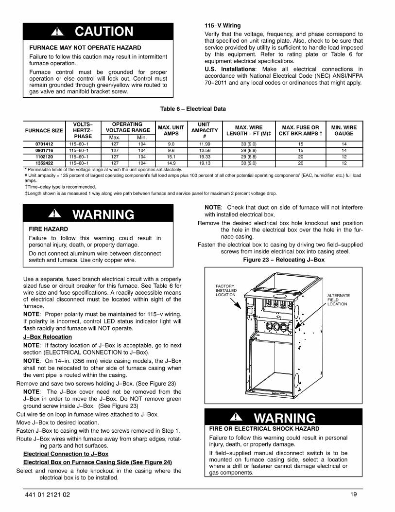
CAUTION!115−V WiringVerify that the voltage, frequency, and phase correspond tothat specified on unit rating plate. Also, check to be sure thatservice provided by utility is sufficient to handle load imposedby this equipment. Refer to rating plate or Table 6 forequipment electrical specifications.U.S. Installations: Make all electrical connections inaccordance with National Electrical Code (NEC) ANSI/NFPA70−2011 and any local codes or ordinances that might apply.
Table 6 – Electrical Data
FURNACE SIZEVOLTS−HERTZ−PHASE
OPERATING VOLTAGE RANGE MAX. UNIT
AMPS
UNIT AMPACITY
#
MAX. WIRELENGTH − FT (M)�
MAX. FUSE ORCKT BKR AMPS �
MIN. WIREGAUGE
Max. Min.0701412 115−60−1 127 104 9.0 11.99 30 (9.0) 15 140901716 115−60−1 127 104 9.6 12.56 29 (8.8) 15 141102120 115−60−1 127 104 15.1 19.33 29 (8.8) 20 121352422 115−60−1 127 104 14.9 19.13 30 (9.0) 20 12
* Permissible limits of the voltage range at which the unit operates satisfactorily.# Unit ampacity = 125 percent of largest operating component’s full load amps plus 100 percent of all other potential operating components’ (EAC, humidifier, etc.) full loadamps.�Time−delay type is recommended.�Length shown is as measured 1 way along wire path between furnace and service panel for maximum 2 percent voltage drop.
FIRE HAZARD
Failure to follow this warning could result inpersonal injury, death, or property damage.
Do not connect aluminum wire between disconnectswitch and furnace. Use only copper wire.
! WARNING
Use a separate, fused branch electrical circuit with a properlysized fuse or circuit breaker for this furnace. See Table 6 forwire size and fuse specifications. A readily accessible meansof electrical disconnect must be located within sight of thefurnace.NOTE: Proper polarity must be maintained for 115−v wiring.If polarity is incorrect, control LED status indicator light willflash rapidly and furnace will NOT operate.
J−Box RelocationNOTE: If factory location of J−Box is acceptable, go to nextsection (ELECTRICAL CONNECTION to J−Box).
NOTE: On 14−in. (356 mm) wide casing models, the J−Boxshall not be relocated to other side of furnace casing whenthe vent pipe is routed within the casing.
Remove and save two screws holding J−Box. (See Figure 23)NOTE: The J−Box cover need not be removed from theJ−Box in order to move the J−Box. Do NOT remove greenground screw inside J−Box. (See Figure 23)
Cut wire tie on loop in furnace wires attached to J−Box.Move J−Box to desired location.Fasten J−Box to casing with the two screws removed in Step 1.Route J−Box wires within furnace away from sharp edges, rotat-
ing parts and hot surfaces.Electrical Connection to J−BoxElectrical Box on Furnace Casing Side (See Figure 24)
Select and remove a hole knockout in the casing where theelectrical box is to be installed.
NOTE: Check that duct on side of furnace will not interferewith installed electrical box.
Remove the desired electrical box hole knockout and positionthe hole in the electrical box over the hole in the fur-nace casing.
Fasten the electrical box to casing by driving two field−suppliedscrews from inside electrical box into casing steel.
Figure 23 − Relocating J−Box
FACTORYINSTALLEDLOCATION ALTERNATE
FIELDLOCATION
FIRE OR ELECTRICAL SHOCK HAZARD
Failure to follow this warning could result in personalinjury, death, or property damage.
If field−supplied manual disconnect switch is to bemounted on furnace casing side, select a locationwhere a drill or fastener cannot damage electrical orgas components.
! WARNING

20 441 01 2121 02
Remove and save two screws holding J−Box. (See Figure 23)Pull furnace power wires out of 1/2−in. (12 mm) diameter hole in
J−Box. Do not loosen wires from strain−relief wire−tieon outside of J−Box.
Route furnace power wires through holes in casing and electric-al box and into electrical box.
Pull field power wires into electrical box.Remove cover from furnace J−Box.Route field ground wire through holes in electrical box and cas-
ing, and into furnace J−Box.Reattach furnace J−Box to furnace casing with screws removed
in Step 4.Secure field ground wire to J−Box green ground screw.Complete electrical box wiring and installation. Connect line
voltage leads as shown in Figure 24. Use best prac-tices (NEC in U.S. for wire bushings, strain relief, etc.
Reinstall cover to J−Box. Do not pinch wires between cover andbracket.
Figure 24 − Field−Supplied Electrical Box on FurnaceCasing
Power Cord Installation in Furnace J−BoxNOTE: Power cords must be able to handle the electricalrequirements listed in Table 5. Refer to power cordmanufacturer’s listings.
Remove cover from J−Box.Route listed power cord through 7/8−in. (22 mm) diameter hole
in J−Box.Secure power cord to J−Box bracket with a strain relief bushing
or a connector approved for the type of cord used.
Secure field ground wire to green ground screw on J−Box brack-et.
Connect line voltage leads as shown in Figure 25. Reinstall cover to J−Box. Do not pinch wires between cover and
bracket.BX Cable Installation in Furnace J−Box
Remove cover from J−Box.Route BX cable into 7/8−in. (22 mm) diameter hole in J−Box.Secure BX cable to J−Box bracket with connectors approved for
the type of cable used.Secure field ground wire to green ground screw on J−Box brack-
et.Connect line voltage leads as shown in Figure 25.Reinstall cover to J−Box. Do not pinch wires between cover and
bracket.24−V WiringMake field 24−v connections at the 24−v terminal strip. (SeeFigure 25 − Figure 33) Connect terminal Y/Y2 as shown inFigure 27−Figure 33 for proper cooling operation. Use onlyAWG No. 18, color−coded, copper thermostat wire.The 24−v circuit contains an automotive−type, 3−amp. fuselocated on the control. Any direct shorts during installation,service, or maintenance could cause this fuse to blow. If fusereplacement is required, use ONLY a 3−amp. fuse of identicalsize.ACCESSORIES
Electronic Air Cleaner (EAC) Connect an accessory Electronic Air Cleaner (if used)using 1/4−in female quick connect terminals to the twomale 1/4−in quick−connect terminals on the controlboard marked EAC−1 and EAC−2. The terminals arerated for 115VAC, 1.0 amps maximum and are ener-gized during blower motor operation. (See Figure 26)
Humidifier (HUM) Connect an accessory 24 VAC, 0.5 amp. maximum hu-midifier (if used) to the 1/4−in male quick−connect HUMterminal and COM−24V screw terminal on the controlboard thermostat strip. The HUM terminal is energizedwhen blower is energized in heating. (See Figure 26)
NOTE: DO NOT connect furnace control HUM terminal to Hterminal on humidity sensing thermostat, or similar device.See the humidity sensing thermostat, instructions for properconnection.VENTINGThe furnace shall be connected to a listed factory builtchimney or vent, or a clay−tile lined masonry or concretechimney. Venting into an unlined masonry chimney orconcrete chimney is prohibited.When an existing Category I furnace is removed or replaced,the original venting system, may no longer be sized toproperly vent the attached appliances. An improperly sizedCategory I venting system could cause the formation ofcondensate in the furnace and vent, leakage of condensateand combustion products, and spillage of combustionproducts into the living space.

21441 01 2121 02
Figure 25 − Field Wiring Diagram
115-VOLT FIELD-SUPPLIED
FUSEDDISCONNECT
JUNCTIONBOX
CONTROLBOX
24-VOLTTERMINALBLOCK
THREE-WIREHEATING-
ONLY
FIVEWIRE
NOTE 2
NOTE 1
1-STAGETHERMOSTATTERMINALS
FIELD-SUPPLIEDFUSED DISCONNECT
CONDENSINGUNIT
FURNACE
COM
R
W C Y R G
GND
GND
FIELD 24-VOLT WIRINGFIELD 115-, 208/230-, 460-VOLT WIRINGFACTORY 24-VOLT WIRINGFACTORY 115-VOLT WIRING
Connect Y/Y2-terminal as shown for proper operation.Some thermostats require a "C" terminal connection as shown.If any of the original wire, as supplied, must be replaced, usesame type or equivalent wire.
208/230- OR460-VOLTTHREEPHASE
208/230-VOLTSINGLEPHASE
WHT
BLK
WHT
BLK
W/W1
W2
Y/Y2
G
NOTES: 1.2.3.
A95236
Figure 26 − Variable Speed Furnace Control for ECM Blower Motor
24-V THERMOSTAT TERMINALS
PL2 – HOT SURFACE IGNITER INDUCER
MOTOR CONNECTOR
115-VAC (L2) NEUTRAL CONNECTIONS
115-VAC (L1) LINE VOLTAGE CONNECTIONS
EAC-1 TERMINAL (115 -VAC 1.0 AMP MAX.)
PL1 – LOW VOLTAGE MAIN HARNESS CONNECTOR
PL3 – ECM BLOWER HARNESS
CONNECTOR
TRANSFORMER 24-VAC CONNECTIONS
3-AMP FUSE
STATUS AND COMM LED LIGHTS
SW1 SETUP SWITCHES AND BLOWER OFF-
DELAY
MODEL PLUG CONNECTOR
AIR CONDITIONING (A/C) AIRFLOW
SETUP SWITCHES
USER INTERFACE OR ADVANCED
PRODUCT MONITOR
CONNECTOR
CONTINUOUS FAN (CF) AIRFLOW
SETUP SWITCHES OAT
CONNECTOR
HUMIDIFIER TERMINAL (24-VAC
0.5 AMP MAX.
ACRDJ – AIR CONDITIONING RELAY DISABLE
JUMPER
FLASH UPGRADE
CONNECTOR (FACTORY
ONLY)
SW4 SETUP SWITCHES
BOARD SERIAL NUMBER
EXAMPLE: V14 HK42FZ022 3410
SOFTWARE VERSION NUMBER
DATE CODE
PART NUMBER
A10286

22 441 01 2121 02
CARBON MONOXIDE POISONING HAZARD
Failure to follow the steps outlined below for eachappliance connected to the venting system being placedinto operation could result in carbon monoxidepoisoning or death.
The following steps shall be followed for each applianceconnected to the venting system being placed intooperation, while all other appliances connected to theventing system are not in operation:
Seal any unused openings in venting system.Inspect the venting system for proper size and horizontal
pitch, as required in the National Fuel Gas Code,NFPA 54/ANSI Z223.1−2012 and theseinstructions. Determine that there is no blockageor restriction, leakage, corrosion and otherdeficiencies, which could cause an unsafecondition.
As far as practical, close all building doors and windowsand all doors between the space in which theappliance(s) connected to the venting system arelocated and other spaces of the building.
Close fireplace dampers.Turn on clothes dryers and any appliance not connected to
the venting system. Turn on any exhaust fans,such as range hoods and bathroom exhausts, sothey are operating at maximum speed. Do notoperate a summer exhaust fan.
Follow the lighting instructions. Place the appliance beinginspected into operation. Adjust the thermostat soappliance is operating continuously.
Test for spillage from draft hood equipped appliances atthe draft hood relief opening after 5 minutes ofmain burner operation. Use the flame of a matchor candle.
If improper venting is observed during any of the abovetests, the venting system must be corrected inaccordance with the National Fuel Gas Code,NFPA 54/ANSI Z223.1−2012.
After it has been determined that each applianceconnected to the venting system properly ventswhen tested as outlined above, return doors,windows, exhaust fans, fireplace dampers andany other gas−fired burning appliance to theirprevious conditions of use.
! WARNING
Vent system or vent connectors may need to be resized. Ventsystems or vent connectors must be sized to approachminimum size as determined using appropriate table found inthe current edition of NFGC.General Venting RequirementsFollow all safety codes for proper vent sizing and installationrequirements, including local building codes, the NationalFuel Gas Code NFPA 54/ANSI Z223.1−2012 (NFGC), Parts12 and 13 in the United States, the local building codes, andfurnace and vent manufacturers’ instructions.The following information and warning must be considered inaddition to the requirements defined in the NFGC.
CARBON MONOXIDE POISONING HAZARD
Failure to follow this warning could result in personalinjury or death.
Do not bypass the draft safeguard switch, as anunsafe condition could exist which must be corrected.
! WARNING
If a vent (common or dedicated) becomes blocked, the furnacewill be shut off by the draft safeguard switch located onthe vent elbow.
Two−stage furnaces require Type B vent connectors outside thecasing in all configurations. Single wall vent connectormay be used inside the furnace casing with the trans-ition to Type B vent outside the furnace casing. Sizethe connector so that the FAN−Min vent connector ca-pacity is equal to or lower than the low fire rate of thefurnace and the FAN−Max vent connector capacity isequal to or higher than the furnace high fire rate.
Do not vent this Category I furnace into a single wall dedicatedor common vent. The dedicated or common vent isconsidered to be the vertical portion of the vent systemthat terminates outdoors.
Vent connectors serving Category I furnaces shall not be con-nected into any portion of a mechanical draft systemoperating under positive pressure.
Do not vent this appliance with any solid fuel burning appliance.
Category I furnaces must be vented vertically or nearly verticallyunless equipped with a listed mechanical venter. SeeSIDEWALL VENTING section.
Do not vent this appliance into an unlined masonry chimney.Refer to Chimney Inspection Chart, Figure 34.
Figure 27 − Variable Speed Furnace with Single StageAir Conditioner
L09F025

23441 01 2121 02
Figure 28 − Variable Speed Furnace with Two−Stage AirConditioner
L09F026
Figure 29 − Variable Speed Furnace with Single StageHeat Pump (Dual Fuel)
L09F027
Figure 30 − Variable Speed Furnace with Two−StageHeat Pump (Dual Fuel)
L09F028
Figure 31 − Variable Speed Furnace and Humidifier Only
L09F029

24 441 01 2121 02
Figure 32 − AC with Variable Speed Furnace, Humidifier,and Dehumidification
L09F029
Figure 33 − HP with Variable Speed Furnace, Humidifier,and Dehumidification
L09F030
NOTES FOR FIGURES Figure 27 − Figure 33Refer to outdoor equipment Installation Instructions for additional information and setup procedure.Outdoor Air Temperature Sensor must be attached in all dual fuel applications.Refer to ICP thermostat Installation Instructions for additional information and setup procedure.When using a Humidity Sensing Thermostat, set DEHUMIDIFY OPTIONS to H DE−ENRGZD FOR DEHUM.Optional connection. If wire is connected SW1−2 on VS furnace control should be set in ON position to allow ICP Thermostat to control
the furnace staging.HUM connection is 24 VAC and is energized when the blower turns on during a call for heat.When connecting 115 VAC to humidifier use a separate 115 VAC supply.When using a humidifier on a HP installation connect humidifier to hot water.
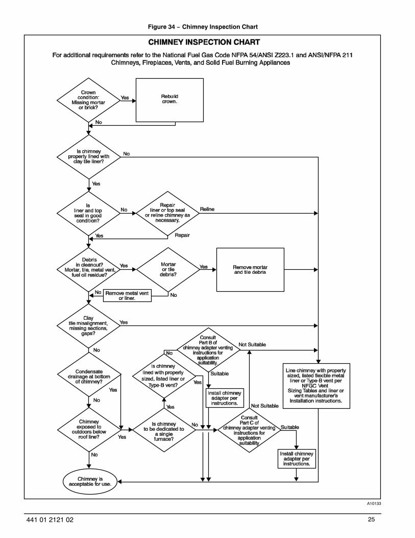
25441 01 2121 02
Figure 34 − Chimney Inspection Chart
A10133

26 441 01 2121 02
Masonry Chimney RequirementNOTE: These furnaces are CSA design−certified for use inexterior tile−lined masonry chimneys with a factory accessoryChimney Adapter Kit. Refer to the furnace rating plate forcorrect kit usage. The Chimney Adapter Kits are for use withONLY furnaces having a Chimney Adapter Kit numbermarked on the furnace rating plate.
If a clay tile−lined masonry chimney is being used and it isexposed to the outdoors below the roof line, relining might berequired. Chimneys shall conform to the Standard forChimneys, Fireplaces, Vents, and Solid Fuel BurningAppliances ANSI/NFPA 211−2012 in the United States andmust be in good condition.U.S.A.−Refer to Sections 13.1.8 and 13.2.20 of the NFPA54/ANSI Z223.1−2012 or the authority having jurisdiction todetermine whether relining is required. If relining is required,use a properly sized listed metal liner, Type−B vent, or alisted alternative venting design.NOTE: See the NFPA 54/ANSI Z223.1−2012 13.1.9 and13.2.20 regarding alternative venting design and theexception, which cover installations such as our ChimneyAdapter Kits which are listed for use with these furnaces.
The Chimney Adapter Kit is a listed alternative ventingsystem for these furnaces. See the kit instructions forcomplete details.This furnace is permitted to be vented into a clay tile−linedmasonry chimney that is exposed to the outdoors below theroof line, provided:
Vent connector is Type−B double−wall, andThis furnace is common vented with at least 1 draft hood
equipped appliance, andThe combined appliance input rating is less than the maximum
capacity given in Table 7, andThe input rating of each space heating appliance is greater than
the minimum input rating given in Table 8 for the local99% Winter Design Temperature. Chimneys having in-ternal areas greater than 38 sq. in. (24516 sq. mm) re-quire furnace input ratings greater than the input rat-ings of these furnaces. See footnote at bottom of Table8, and
The authority having jurisdiction approves.If all of these conditions cannot be met, an alternative ventingdesign shall be used, such as the listed chimney adapter kitwith a furnace listed for use with the kit, a listedchimney−lining system, or a Type−B common vent.Inspections before the sale and at the time of installation willdetermine the acceptability of the chimney or the need forrepair and/or (re)lining. Refer to the Figure 34 to perform achimney inspection. If the inspection of a previously usedtile−lined chimney:
a. Shows signs of vent gas condensation, the chim-ney should be relined in accordance with localcodes and the authority having jurisdiction. Thechimney should be relined with a listed metal liner,Type−B vent, or a listed chimney adapter kit shallbe used to reduce condensation. If a condensatedrain is required by local code, refer to the NFPA54/ANSI Z223.1−2012, Section 12.10 for additionalinformation on condensate drains.
b. Indicates the chimney exceeds the maximum per-missible size in the tables, the chimney should be
rebuilt or relined to conform to the requirements ofthe equipment being installed and the authority hav-ing jurisdiction.
A chimney without a clay tile liner, which is otherwise in goodcondition, shall be rebuilt to conform to ANSI/NFPA 211 or belined with a UL listed metal liner or UL listed Type−B vent.Relining with a listed metal liner or Type−B vent is consideredto be a vent−in−a−chase.If a metal liner or Type−B vent is used to line a chimney, noother appliance shall be vented into the annular spacebetween the chimney and the metal liner.
Exterior Masonry Chimney FAN + NATInstallations with Type−B Double−Wall Vent
Connectors �NFPA & AGATable 7 – Combined Appliance Maximum Input
Rating in Thousands of Btuh per Hour
VENT HEIGHTFT (M)
INTERNAL AREA OF CHIMNEYSQ. IN. (SQ. MM)
12(7741)
19(12258)
28(18064)
38(24516)
6 (1.8) 74 119 178 2578 (2.4) 80 130 193 27910 (3.0) 84 138 207 29915 (4.5) NR 152 233 33420 (6.0) NR NR 250 36830 (9.1) NR NR NR 404
Appliance Application RequirementsAppliance operation has a significant impact on theperformance of the venting system. If the appliances aresized, installed, adjusted, and operated properly, the ventingsystem and/or the appliances should not suffer fromcondensation and corrosion. The venting system and allappliances shall be installed in accordance with applicablelistings, standards, and codes.The furnace should be sized to provide 100 percent of thedesign heating load requirement plus any margin that occursbecause of furnace model size capacity increments. Heatingload estimates can be made using approved methodsavailable from Air Conditioning Contractors of America(Manual J); American Society of Heating, Refrigerating, andAir−Conditioning Engineers; or other approved engineeringmethods. Excessive oversizing of the furnace could causethe furnace and/or vent to fail prematurely.When a metal vent or metal liner is used, the vent must be ingood condition and be installed in accordance with the ventmanufacturer’s instructions.To prevent condensation in the furnace and vent system, thefollowing precautions must be observed:
The return−air temperature must be at least 60�F db except forbrief periods of time during warm−up from setback atno lower than 55�F (13�C) db or during initial start−upfrom a standby condition.
Adjust the gas input rate per the installation instructions. Lowgas input rate causes low vent gas temperatures,causing condensation and corrosion in the furnaceand/or venting system. Derating is permitted only foraltitudes above 2000 Ft. (610 M).
Adjust the air temperature rise to the midpoint of the rise rangeor slightly above. Low air temperature rise can causelow vent gas temperature and potential for condensa-tion problems.
Set the thermostat heat anticipator or cycle rate to reduce shortcycling.

27441 01 2121 02
BURN HAZARD
Failure to follow this caution may result in personalinjury.
Hot vent pipe is within reach of small children wheninstalled in downflow position.
See the following instruction.
CAUTION!
Table 8 – Minimum Allowable Input Rating ofSpace−Heating Appliance in Thousands of Btuh per Hour
VENT HEIGHTFT. (M)
INTERNAL AREA OF CHIMNEY
SQ. IN. (SQ. MM)12
(7741)19
(12258)28
18064)38
(24516)Local 99% Winter Design Temperature: 17 to 26 degrees F
6 0 55 99 1418 52 74 111 15410 NR 90 125 16915 NR NR 167 21220 NR NR 212 25830 NR NR NR 362
Local 99% Winter Design Temperature: 5 to 16 degrees F*6 NR 78 121 1668 NR 94 135 18210 NR 111 149 19815 NR NR 193 24720 NR NR NR 29330 NR NR NR 377
Local 99% Winter Design Temperature: −10 to 4 degrees F*6 NR NR 145 1968 NR NR 159 21310 NR NR 175 23115 NR NR NR 28320 NR NR NR 33330 NR NR NR NR
Local 99% Winter Design Temperature: −11 degrees F or lower
Not recommended for any vent configuration.
*The 99.6% heating (db) temperatures found in the 1997 or 2001 ASHRAE Fundamentals Handbook, Climatic Design Information chapter, Table1A (United States) and 2A (Canada) or the 2005 ASHRAE Fundamentalshandbook, Climatic Design Information chapter, and the CD−ROM includedwith the 2005 ASHRAE Fundamentals Handbook.
Air for combustion must not be contaminated by halogencompounds which include chlorides, fluorides, bromides, andiodides. These compounds are found in many common homeproducts such as detergent, paint, glue, aerosol spray,bleach, cleaning solvent, salt, and air freshener, and cancause corrosion of furnaces and vents. Avoid using suchproducts in the combustion−air supply. Furnace use duringconstruction of the building could cause the furnace to beexposed to halogen compounds, causing premature failure ofthe furnace or venting system due to corrosion.Vent dampers on any appliance connected to the commonvent can cause condensation and corrosion in the ventingsystem. Do not use vent dampers on appliances commonvented with this furnace.
Additional Venting RequirementsA 4−in. (102 mm) round vent elbow is supplied with thefurnace. A 5−in. (127 mm) or 6− in. (152 mm) vent connectormay be required for some model furnaces. A field−supplied4−in. (102 mm) to 5−in. (127 mm) or 4−in. (102 mm) to 6−in.(152 mm) sheet metal increaser fitting is required when 5−in.(127 mm) or 6−in. (152 mm) vent connector is used. SeeFigure 35 − Figure 47, Venting Orientation for approved ventconfigurations.NOTE: Vent connector length for connector sizing starts atfurnace vent elbow. The 4−in. (102 mm) vent elbow isshipped for upflow configuration and may be rotated for otherpositions. Remove the three screws that secure vent elbow tofurnace, rotate furnace vent elbow to position desired,reinstall screws. The factory−supplied vent elbow does NOTcount as part of the number of vent connector elbows.
The vent connector can exit the furnace through one of fivelocations on the casing.
CUT HAZARD
Failure to follow this caution may result in personal injury.
Sheet metal parts may have sharp edges or burrs. Usecare and wear appropriate protective clothing, safetyglasses and gloves when handling parts, and servicingfurnaces.
CAUTION!
Attach the single wall vent connector to the furnace vent elbow,and fasten the vent connector to the vent elbow with atleast two field−supplied, corrosion−resistant, sheetmetal screws located 180� apart.
NOTE: A flue extension is recommended to extend from thefurnace elbow to outside the furnace casing. If flue extensionis used, fasten the flue extension to the vent elbow with atleast two field−supplied, corrosion−resistant, sheet metalscrews located 180� apart. Fasten the vent connector to theflue extension with at least two field−supplied, corrosionresistant sheet metal screws located 180� apart.
Vent the furnace with the appropriate connector as shown inFigure 35 − Figure 47.
Determine the correct location of the knockout to be removed.Use a hammer and screwdriver to strike a sharp blow between
the tie points and work the slug back and forth until theslug breaks free.
An accessory Vent Guard Kit is REQUIRED for downflowapplications for use where the vent exits through the lowerportion of the furnace casing door. Refer to the Vent Guard KitInstructions for complete details.

28 441 01 2121 02
Figure 35 − Upflow Application − Vent Elbow Up
SEE NOTES: 1,2,4,7,8,9on the page followingthese figures
A03208
Figure 36 − Upflow Application − Vent Elbow Right
SEE NOTES: 1,2,3,4,7,8,9on the pages followingthese figures
A03209
Figure 37 − Downflow Application − Vent Elbow Up thenLeft
SEE NOTES:1,2,3,4,5,7,8,9on the page followingthese figures
A03210
Figure 38 − Downflow Application − Vent Elbow Up
SEE NOTES: 1,2,4,5,7,8,9on the page followingthese figures
A03211
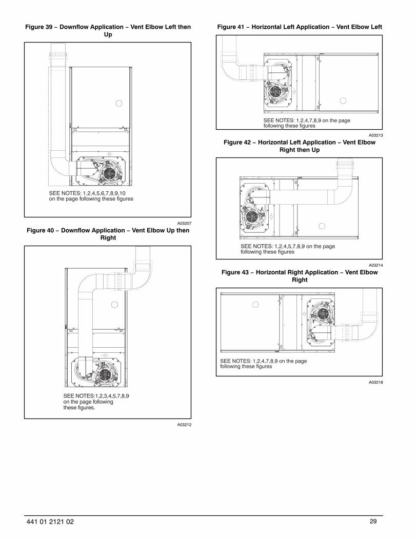
29441 01 2121 02
Figure 39 − Downflow Application − Vent Elbow Left thenUp
SEE NOTES: 1,2,4,5,6,7,8,9,10on the page following these figures
A03207
Figure 40 − Downflow Application − Vent Elbow Up thenRight
SEE NOTES:1,2,3,4,5,7,8,9on the page followingthese figures.
A03212
Figure 41 − Horizontal Left Application − Vent Elbow Left
SEE NOTES: 1,2,4,7,8,9 on the pagefollowing these figures
A03213
Figure 42 − Horizontal Left Application − Vent ElbowRight then Up
SEE NOTES: 1,2,4,5,7,8,9 on the pagefollowing these figures
A03214
Figure 43 − Horizontal Right Application − Vent ElbowRight
SEE NOTES: 1,2,4,7,8,9 on the pagefollowing these figures
A03218

30 441 01 2121 02
Figure 44 − Horizontal Left Application − Vent Elbow Up
SEE NOTES: 1,2,4,5,7,8,9 on the pagefollowing these figures
A03215
Figure 45 − Horizontal Left Application − Vent ElbowRight
SEE NOTES: 1,2,4,5,7,8,9 on the pagefollowing these figures
A03216
Figure 46 − Horizontal Right Application − Vent ElbowLeft then Up
SEE NOTES: 1,2,4,5,7,8,9 on the pagefollowing these figures
A03219
Figure 47 − Horizontal Right Application−Vent Elbow Left
SEE NOTES: 1,2,4,5,7,8,9
A02068
VENTING NOTES FOR Figure 35 − Figure 47For common vent, vent connector sizing and vent material:
United States−−use the NFGC.Immediately increase to 5−in. (102 mm) or 6−in. (152 mm) vent
connector outside furnace casing when 5−in. (127 mm)vent connector is required, refer to Note 1 above.
Side outlet vent for upflow and downflow installations must useType B vent immediately after exiting the furnace, ex-pect when Downflow Vent Guard Kit is used in thedownflow position.
Type−B vent where required, refer to Note 1 above.A 4−in.(102 mm) single−wall (26 ga. min.) vent must be used
inside furnace casing and when the NAHB00301VCDownflow Vent Guard Kit is used external to thefurnace.
Accessory Downflow Vent Guard Kit is required in downflowinstallations with lower vent configuration.
Chimney Adapter Kit may be required for exterior masonrychimney applications. Refer to Chimney Adapter Kit forsizing and complete application details.
Secure vent connector to furnace elbow with (2) corrosion−resistant sheet metal screws, spaced approximately180� apart.
Secure all other single wall vent connector joints with (3)corrosion resistant screws spaced approximately 120�apart. Secure Type−B vent connectors per ventconnector manufacturer’s recommendations.
NOTE: For the following applications, use the minimum vertical heights as specified below. For all other applications, follow exclusively the National Fuel Gas Code.
FURNACEORIENTATION
VENT ORIENTATION FURNACE INPUT(BTUH/HR)
MIN. VENT DIAMETERIN. (mm)*
MIN. VERTICAL VENTHEIGHTFT. (M)**
Downflow Vent elbow left, then up Figure 35 132,000/110,000 (3 ton only) 5 (127) 12 (3.6)Horizontal Left Vent elbow right, then up Figure 38 132,000 5 (127) 7 (2.1)Horizontal Left Vent Elbow up Figure 39 132,000 5 (127) 7 (2.1)
Downflow Vent elbow up then left Figure 33 110,000 (3 ton only) 5 (127) 10 (3.0)Downflow Vent elbow up, then right Figure 36 110,000 (3 ton only) 5 (127) 10 (3.0)
NOTE: All vent configurations must also meet National Fuel Gas Code venting requirements NFGC.*4−in. (102 mm) inside casing or vent guard**Including 4 in. (102 mm) vent section(s)

31441 01 2121 02
The horizontal portion of the venting system shall slopeupwards not less than 1/4−in. per linear ft. (21 mm/m) fromthe furnace to the vent and shall be rigidly supported every 5ft. (1.5 M) or less with metal hangers or straps to ensure thereis no movement after installation.Sidewall VentingThis furnace is not approved for direct sidewall horizontalventing.Per section 12.4.3 of the NFPA 54/ANSI Z223.1−2012, anylisted mechanical venter may be used, when approved by theauthority having jurisdiction.Select the listed mechanical venter to match the Btuh input ofthe furnace being vented. Follow all manufacturer’sinstallation requirements for venting and termination includedwith the listed mechanical venter.
START−UP, ADJUSTMENT, AND SAFETYCHECK
General
FIRE HAZARD
Failure to follow this warning could result in personalinjury, death or property damage.
This furnace is equipped with manual reset limitswitches in the gas control area. The switches openand shut off power to the gas valve, if a flame rollout oroverheating condition occurs in the gas control area.DO NOT bypass the switches. Correct problem beforeresetting the switches.
! WARNING
Maintain 115−v wiring and ground. Improper polarity will result inrapid flashing LED and no furnace operation.
Make thermostat wire connections at the 24−v terminal block onthe furnace control. Failure to make proper connectionswill result in improper operation. (See Figure 25 −Figure 33)
Gas supply pressure to the furnace must be greater than 4.5−In.W.C. (0.16 psig ) but not exceed 14−In. W.C. (0.5 psig).
Check all manual−reset switches for continuity.Replace blower compartment door. Door must be in place to op-
erate furnace.Setup switch descriptions The variable speed furnace control
has DIP switches to select thermostat staging, bloweroff delay timings, air flow selection and other operation-al or service related functions. (See Figure 26,Figure 56 and Table 9)
CUT HAZARD
Failure to follow this caution may result in personal injury.
Sheet metal parts may have sharp edges or burrs. Usecare and wear appropriate protective clothing, safetyglasses and gloves when handling parts, and servicingfurnaces.
CAUTION!
Figure 48 − Redundant Automatic Gas Control Valve
REGULATOR COVER SCREW
PLASTIC ADJUST SCREW
LOW STAGE GAS PRESSURE REGUL ATOR ADJUSTMENT
MANIFOLDPRESSURE TAP
INLETPRESSURE TAP
ON/OFF SWITCH
REGULATOR SPRING
HIGH STAGE GAS PRESSURE REGUL ATOR ADJUSTMENT
1/2¿ NPT OUTLET
1/2¿ NPT INLET
A04167
Figure 49 − Orifice Hole
BURNERORIFICE
A93059
Figure 50 − Amp. Draw Check with Ammeter
R Y W G
10 TURNS
THERMOSTAT SUBBASETERMINALS WITHTHERMOSTAT REMOVED(ANITICIPATOR, CLOCK, ETC.,MUST BE OUT OF CIRCUIT.)
HOOK-AROUNDAMMETER
EXAMPLE: 5.0 AMPS ON AMMETER10 TURNS AROUND JAWS
= 0.5 AMPS FOR THERMOSTAT ANTICIPATOR SETTING
FROM UNIT 24-VCONTROL TERMINALS
A96316

32 441 01 2121 02
Start−Up Procedures
FIRE OR EXPLOSION HAZARD
Failure to follow this warning could result in personalinjury, death, and/or property damage.
Never purge a gas line into a combustion chamber.Never test for gas leaks with an open flame. Use acommercially available soap solution madespecifically for the detection of leaks to check allconnections. A fire or explosion may result causingproperty damage, personal injury or loss of life.
! WARNING
ELECTRICAL SHOCK HAZARD
Failure to follow this warning could result in personalinjury, or death.
Blower access door switch opens 115−v power tocontrol. No component operation can occur unlessswitch is closed. Caution must be taken whenmanually closing this switch for service purposes.
! WARNING
Purge gas lines after all connections have been made.Check gas lines for leaks.To Begin Component Self−Test:
Remove Blower Access Door. Disconnect the thermo-stat R lead from furnace control board. Manually closeblower door switch. Turn Setup DIP switch SW1−6 ON.(See Figure 26, Figure 56 and Table 9)
NOTE: The furnace control allows all components, exceptthe gas valve, to be run for short period of time. This featurehelps diagnose a system problem in case of a componentfailure. Component test feature will not operate if anythermostat signal is present at the control.
Refer to service label attached to furnace or See Figure 52.Component test sequence is as follows:
a. Inducer motor starts on high−speed and continuesto run until Step d. of component test sequence.
b. Hot surface igniter is energized for 15 sec., then off.c. Blower motor operates for 15 sec.d. Inducer motor goes to low−speed for 10 sec., then
stops.e. After component test is completed, one or more
status codes (heartbeat, 2+5, or 4+1) will flash. Seecomponent test section of service label (Figure 52)in furnace for explanation of status codes.
NOTE: To repeat component test, turn setup switch SW1−6OFF, then back ON.
Turn setup DIP switch SW1−6 OFF. Reconnect R lead to fur-nace control board, release blower door switch and re-install blower access door.
Operate furnace per instruction on inner door.Verify furnace shut down by lowering thermostat setting below
room temperature.Verify furnace restarts by raising thermostat setting above room
temperature.
Adjustments
FIRE HAZARD
Failure to follow this warning could result in personalinjury, death and/or property damage.
DO NOT bottom out gas valve regulator adjustingscrew. This can result in unregulated manifoldpressure and result in excess overfire and heatexchanger failures.
! WARNING
FURNACE DAMAGE HAZARD
Failure to follow this caution may result in reducedfurnace life.
DO NOT redrill orifices. Improper drilling (burrs,out−of−round holes, etc.) can cause excessive burnernoise and misdirection of burner flames. This canresult in flame impingement of heat exchangers,causing failures. (See Figure 49)
CAUTION!

33441 01 2121 02
Table 9 – Furnace Setup Switch Description
L12F035
SETUP SWITCH SWITCH NAME NORMAL POSITION DESCRIPTION OF USE
Furnace Setup Switch Description
SW1 1 Status Code Recovery OFFTurn ON to retrieve up to 7 stored status codes for troubleshooting assistance when R thermostat lead isdisconnected.
SW1 2Low Heat Only
(Adaptive Heat Mode when SW12 is OFF)
OFF
When SW1 2 is OFF allows two stage operation with a single stage thermostat. Turn ON when using twostage thermostat to allow Low Heat operation when R to W/W1 closes and High Heat operation when R to W/W1 and W2 close.
SW1 3 Low Heat Rise Adjustment OFF
Turn ON to increase Low Heat airflow by 18 percent. This compensates for increased return air temperature caused with bypass humidifier. This also increases the low heat inducer speed 15 percent.
SW1 4 Comfort/Efficiency Adjustment ONTurn ON to decrease low heat airflow by 7 percent, and high heat airflow 10 percent for maximum comfort.
SW1 5 CFM per ton adjust OFFTurn ON for 400 CFM per ton, Turn OFF for 350 CFM per ton. See also SW4.
SW1 6 Component Self Test OFF
Turn ON to initiate Component Self Test for troubleshooting assistance when R thermostat lead is disconnected. Turn OFF when Self Test is completed.
SW1 7 & SW1 8 Blower OFF delay ON or OFFBlower Off Delay time – adjustable 90 seconds to 180 seconds. See table in Adjustments section or refer to unit wiring diagram.
SW4 3CFM per ton Adjust
OFF
Allows additional CFM per ton selections when used with SW 1 5
325 CFM per ton (nominal) when SW 4 3 ON and SW 1 5 OFF
350 CFM per ton (nominal) when SW 4 3 OFF and SW 1 5 OFF
370 CFM per ton (nominal) when SW4 3 ON and SW 1 5 ON
400 CFM per ton (nominal) when SW 1 5 ON and SW4 3 OFF
See Air Delivery Tables for model specific CFM vs. static pressure
AIR CONDITIONING (A/C) SETUP SWITCHES
SW 2, AC (Cooling Airflow) SETUP SWITCHES
ON1
1
2
The AC setup switch selects desired cooling or high stage cooling (two stage units) airflow.
See Cooling Air Delivery Tables for specific switch settings.
CONTINUOUS FAN (CF) SETUP SWITCHES
SW 3, CF (Continuous Fan) SETUP SWITCHES
The CF setup switch selects desired Continuous Fan Airflow
ON1
23
1
SW
3
23
AC
SW
2
The CF switch position is the low cooling airflow selection for two stage cooling units.
The CFM values are shown in the Air Delivery Tables below for SW 3 settings.SW 3 cannot be set for airflow higher than SW 2.
See Continuous Fan Air Flow Table for specific switch settings.
3
CF

34 441 01 2121 02
Figure 51 − Cooling (A/C) or Continuous−Fan (CF) Airflow Selection Chart
L13F018
AIR CONDITIONING AIRFLOW 070 MODEL 090 MODEL 110, 135TONS (12,000 BTU/HR) (CFM) & MODELS
1-1/2 525 X X
2 700 X X X
2-1/2 875 X X X
3 1050 X X X
3-1/2 1225 X X X
4 1400 X X
5 1750 X
6 2100 X
X-INDICATES AN ALLOWABLE SELECTION.
2
1
2
1
1
2
COOLING TONNAGE VS. AIRFLOW (CFM)
1. DEFAULT A/C AIRFLOW WHEN A/C SWITCHES ARE IN OFF POSITION 2. DEFAULT CONT. FAN AIRFLOW WHEN CF SWITCHES ARE IN OFF POSITION 3. SWITCH POSITIONS ARE ALSO SHOWN ON FURNACE WIRING DIAGRAM
5252
700
700
8752 1050
875 10501
1225
1225
1400
1225
17501
1225
2100
DEF.
DEF.
070
BASED ON 350 CFM/TON (SETUP SWITCH SW1-5 OFF, SW4-3 OFF)
SETUP SWITCH SW2 OR SW3 POSITIONS MODEL
SIZE
5252 700 875 1050 1225 14001 1400 DEF. 090
6002 800 1000 12001 1400 1400 1400 DEF.
BASED ON 400 CFM/TON (SETUP SWITCH SW1-5 ON, SW4-3 OFF)
SETUP SWITCH SW2 OR SW3 POSITIONS MODEL
SIZE
800 10002 1200 1400 1600 20001 2200 DEF.
6002 800 1000 1200 1400 16001 1600 DEF.
4882
651
651
8142 976
814 9761
1139
1139
1302
1139
16271
1139
1950
DEF.
DEF.
070
110, 135
BASED ON 325 CFM/TON (SETUP SWITCH SW1-5 OFF, SW4-3 ON)
SETUP SWITCH SW2 OR SW3 POSITIONS MODEL
SIZE
4882 651 814 976 1139 13021 1302 DEF. 090
5582
744
744
9302 1116
930 11161
1302
1302
1488
1302
18601
1302
2200
DEF.
DEF.
070
110, 135
BASED ON 370 CFM/TON (SETUP SWITCH SW1-5 ON, SW4-3 ON)
SETUP SWITCH SW2 OR SW3 POSITIONS MODEL
SIZE
5582 744 930 1116 1302 14881 1488 DEF. 090
070
090
110, 135
110, 135

35441 01 2121 02
Table 10 – Air Delivery − CFM (with filter)*
Unit Size Operating Mode
CFMAirflowSetting
ExternalStatic
PressureRange*
(In. W.C.)
External Static Pressure (ESP) (IN. W.C.)
0.1 0.2 0.3 0.4 0.5 0.6 0.7 0.8 0.9 10701412 AIRFLOW (CFM)
†† Low Heat 735 (615)† 0−0.50 735 735 735 735 725
High Heat 1180 (1060)† 0−1.0 1160 1165 1175 1180 1180 1180 1180 1180 1180 1175†† 1−1/2−Ton Cooling 525 0−0.50‡ 515 500 500 490 485†† 2−Ton A/C Cooling 700 0−0.50‡ 690 680 675 680 675
2−1/2−Ton A/C Cooling 875 0−1.0‡ 875 875 875 870 865 855 850 835 825 820
3−Ton A/C Cooling 1050 0−1.0‡ 1050 1050 1050 1050 1050 1050 1045 1035 1020 1000
3−1/2−Ton A/C Cooling 1225 0−1.0 1220 1225 1225 1225 1225 1220 1205 1190 1185 1170
Maximum 1400 0−1.0 1395 1400 1400 1400 1395 1385 1370 1340 1300 1245
0901716
Low Heat 985 (825)† 0−1.0 950 970 985 985 985 985 985 985 985 980
High Heat 1210 (1090)† 0−1.0 1190 1205 1210 1210 1210 1210 1210 1210 1210 1200
†† 1−1/2−Ton A/C Cooling 525 0−0.50‡ 525 520 525 495 475†† 2−Ton A/C Cooling 700 0−0.50‡ 680 680 680 675 670
2−1/2−Ton A/C Cooling 875 0−1.0‡ 815 845 845 855 850 850 845 835 820 805
3−Ton A/C Cooling 1050 0−1.0‡ 1005 1005 1015 1035 1040 1040 1035 1030 1025 1010
3−1/2−Ton A/C Cooling 1225 0−1.0 1190 1200 1200 1205 1205 1215 1205 1200 1185 1170
4−Ton A/C Cooling 1400 0−1.0 1350 1370 1390 1390 1400 1390 1380 1380 1360 1340
Maximum 1600 0−1.0 1595 1600 1600 1600 1595 1555 1505 1465 1430 1390
1102120***
Low Heat 1320 (1110)† 0−1.0 1275 1295 1315 1320 1320 1320 1320 1320 1320 1315
High Heat 1475 (1330)† 0−1.0 1460 1465 1475 1475 1475 1475 1475 1475 1465 1465
†† 2−Ton A/C Cooling 700 0−0.50‡ 700 700 700 700 700†† 2−1/2−Ton A/C Cooling 875 0−0.50‡ 875 875 875 875 875†† 3−Ton A/C Cooling 1050 0−0.50‡ 1050 1050 1050 1050 1050
3−1/2−Ton A/C Cooling 1225 0−1.0‡ 1225 1225 1225 1225 1225 1225 1225 1225 1225 1225
4−Ton A/C Cooling 1400 0−1.0‡ 1400 1400 1400 1400 1400 1400 1400 1400 1400 1400
5−Ton A/C Cooling 1750 0−1.0‡ 1750 1750 1750 1750 1750 1750 1750 1750 1740 1725
6−Ton A/C Cooling 2100 0−1.0 2100 2100 2100 2100 2090 2075 2055 2040 2005 1970
Maximum 2200 0−1.0 2200 2190 2190 2180 2155 2145 2125 2100 2080 2020
1352422
Low Heat 1700 (1430)† 0−1.0 1700 1700 1700 1700 1700 1695 1700 1695 1685 1670
High Heat 1915 (1725)† 0−1.0 1900 1905 1915 1915 1915 1915 1915 1915 1915 1915
†† 2−Ton A/C Cooling 700 0−0.50‡ 700 700 700 700 665†† 2−1/2−Ton A/C Cooling 875 0−0.50‡ 870 870 865 865 865†† 3−Ton A/C Cooling 1050 0−0.50‡ 1010 1030 1050 1050 1050
3−1/2−Ton A/C Cooling 1225 0−1.0‡ 1155 1180 1200 1210 1220 1225 1225 1225 1225 1225
4−Ton A/C Cooling 1400 0−1.0‡ 1395 1400 1400 1400 1400 1400 1400 1390 1375 1355
5−Ton A/C Cooling 1750 0−1.0‡ 1740 1750 1750 1750 1735 1740 1735 1730 1715 1700
6−Ton A/C Cooling 2100 0−1.0 2075 2085 2090 2100 2100 2100 2090 2080 2055 2025
Maximum 2200 0−1.0 2180 2195 2200 2200 2200 2200 2185 2165 2140 2095
Air Delivery−CFM Notes*Actual external static pressure (ESP) can be determined by using the fan laws (CFM 2 proportional to ESP); such as, a system with 1180 CFM at 0.5ESP would operate at cooling airflow of 1050 CFM at 0.4 ESP and low-heating airflow of 735 CFM at 0.19 ESP.
�Comfort airflow values are shown in parenthesis. Comfort airflow is selected when the low-heat rise adjustment switch (SW1-3) is OFF and thecomfort/efficiency switch (SW1-4) is ON.
�Ductwork must be sized for high-heating CFM within the operational range of ESP.
��Operation within the blank areas of the chart is not recommended because high-heat operation will be above 1.0 ESP.
***All airflow on 110 size furnace are 5% less on side return only installations.

36 441 01 2121 02
Figure 52 − Service Label

37441 01 2121 02
Furnace gas input rate on rating plate is for installations ataltitudes up to 2000 Ft. (610 M). Furnace input rate must bewithin +/−2 percent of furnace rating plate input. For altitudesabove 5500 Ft. (1676 M), a field−supplied high altitudepressure switch is required.
Determine the correct gas input rate. The input rating for altitudes above 2,000 ft. (610 M)must be reduced by 4 percent for each 1,000 ft. (305M) above sea level. For installations below 2000 Ft. (610 M), refer to theunit rating plate. For installations above 2000 Ft. (610M), multiply the input on the rating plate by the de−ratemultiplier in Table 9 for the correct input rate.
Determine the correct orifice and manifold pressure adjustment.All models in all positions except Low NOx models indownflow and horizontal positions use Table 14(22,000 Btuh per burner.) Low NOx models in down-flow or horizontal positions must use Table 15 (21,000Btuh per burner.) See input listed on rating plate.a. Obtain average yearly gas heat value (at installed
altitude) from local gas supplier.b. Obtain average yearly gas specific gravity from loc-
al gas supplier.c. Find installation altitude in Table 14 or 15.d. Find closest natural gas heat value and specific
gravity in Table 14 or 15.e. Follow heat value and specific gravity lines to point
of intersection to find orifice size and low−and high−heat manifold pressure settings for proper opera-tion.
f. Check and verify burner orifice size in furnace.NEVER ASSUME ORIFICE SIZE. ALWAYS CHECKAND VERIFY.
NOTE: If orifice hole appears damaged or it is suspected tohave been redrilled, check orifice hole with a numbered drillbit of correct size. Never redrill an orifice. A burr−free andsquarely aligned orifice hole is essential for proper flamecharacteristics.
g. Replace orifice with correct size, if required byTable 14 or 15. Use only factory−supplied orifices.See EXAMPLE 1.
Table 11 – Altitude Derate Multiplier for U.S.A.
ALTITUDEFT. (M)
PERCENTOF DERATE
DERATE MULTIPLIERFACTOR*
0–2000(0−610) 0 1.00
2001–3000(610−914) 8–12 0.90
3001–4000(914−1219) 12–16 0.86
4001–5000(1219−1524) 16–20 0.82
5001–60001524−1829) 20–24 0.78
6001–7000(1829−2134) 24–28 0.74
7001–8000(2134−2438) 28–32 0.70
8001–9000(2438−2743) 32–36 0.66
9001–10,000(2743−3048) 36–40 0.62
Table 12 – Blower Off Delay Setup Switch
DESIRED HEATING MODEBLOWER OFF DELAY (SEC.)
SETUP SWITCH (SW−7 AND −8) POSITION
SW1−7 SW1−890 OFF OFF120 ON OFF150 OFF ON180 ON ON
EXAMPLE 1: 0–2000 ft. (0−610 M) altitudeFor 22,000 Btuh per burner application use Table 14.Heating value = 1000 Btuh/cu ft.Specific gravity = 0.62Therefore: Orifice No. 43*Manifold pressure: 3.7−In. W.C. for high−heat1.6−In. W.C. for low−heat* Furnace is shipped with No. 43 orifices. In this exampleall main burner orifices are the correct size and donot need to be changed to obtain proper input rate.
Adjust manifold pressure to obtain low fire input rate. (SeeFigure 48)a. Turn gas valve ON/OFF switch to OFF.b. Remove manifold pressure tap plug from gas valve.c. Connect a water column manometer or similar
device to manifold pressure tap.d. Turn gas valve ON/OFF switch to ON.e. Move setup SW1—2 on furnace control to ON posi-
tion to lock furnace in low−heat operation. (SeeTable 9 and Figure 24)
f. Manually close blower door switch.g. Jumper R and W/W1 thermostat connections on
control to start furnace. (See Figure 24)h. Remove regulator adjustment cap from low heat
gas valve pressure regulator (See Figure 48) andturn low−heat adjusting screw (3/16 or smaller flat−tipped screwdriver) counterclockwise (out) to de-crease input rate or clockwise (in) to increase inputrate.
NOTE: DO NOT set low−heat manifold pressure less than1.4−In. W.C. or more than 1.7−In. W.C. for natural gas. Ifmanifold pressure is outside this range, change main burnerorifices.
i. Install low−heat regulator adjustment cap.j. Move setup switch SW1−2 to off position after com-
pleting low−heat adjustment.k. Leave manometer or similar device connected and
proceed to Step 4.Adjust manifold pressure to obtain high fire input rate. (See
Figure 48)a. Jumper R to W/W1 and W2 thermostat connections
on furnace control. This keeps furnace locked inhigh−heat operation.
b. Remove regulator adjustment cap from high−heatgas valve pressure regulator (See Figure 48) andturn high heat adjusting screw (3/16−in. or smallerflat−tipped screwdriver) counterclockwise (out) todecrease input rate or clockwise (in) to increaseinput rate.
NOTE: DO NOT set high−heat manifold pressure less than3.2−In. W.C. or more than 3.8 In. W.C. for natural gas. If

38 441 01 2121 02
manifold pressure is outside this range, change main burnerorifices to obtain manifold pressure in this range.
c. When correct input is obtained, replace caps thatconceal gas valve regulator adjustment screws.Main burner flame should be clear blue, almosttransparent (See Figure 54)
d. Remove jumpers R to W/W1 and R to W2. Verify natural gas input rate by clocking meter.
a. Turn off all other gas appliances and pilots servedby the meter.
b. Move setup switch SW1−2 to ON position. Thiskeeps furnace locked in low−heat operation.
c. Jumper R to W/W1.d. Run furnace for 3 minutes in low−heat operation.e. Measure time (in sec) for gas meter to complete 1
revolution and note reading. The 2 or 5 cubic feetdial provides a more accurate measurement of gasflow.
f. Refer to Table 13 for cubic ft. of gas per hr.g. Multiply gas rate cu ft./hr by heating value (Btuh/cu
ft.) to obtain input. If clocked rate does not matchrequired input from Step 1, increase manifold pres-sure to increase input or decrease manifold pres-sure to decrease input. Repeat steps b through euntil correct low−heat input is achieved. Re−installlow heat regulator seal cap on gas valve.
h. Move setup switch SW1−2 to OFF position andjumper R to W/W1, and W2. This keeps furnacelocked in high−heat operation. Repeat items dthrough g for high−heat operation.
Set Temperature RiseNOTE: Blower access door must be installed when takingtemperature rise reading. Leaving blower access door off willresult in incorrect temperature measurements.
FURNACE DAMAGE HAZARD
Failure to follow this caution may result in shortenfurnace life.
Set air temperature rise within limits specified on therating plate to prevent reduced life of furnacecomponents. Operation is within a few degrees of themid−point of rise range when setup switch SW1−4 isOFF.
CAUTION!
UNIT DAMAGE HAZARD
Failure to follow this caution may result in overheatingthe heat exchangers or condensing flue gases in heatexchanger areas not designed for condensate.
Temperature rise must be within limits specified onunit rating plate. Operation is within a few degrees ofmidpoint of rise range when setup switch SW1−4 isOFF.
CAUTION!
When setup switch SW1−4 is ON, operation will be near thehigh end of the rise range for improved comfort.Furnace must operate within ranges of temperature risespecified on the furnace rating plate. Determine airtemperature rise as follows:
a. Place thermometers in return and supply ducts asnear furnace as possible. Be sure thermometers donot see heat exchanger so that radiant heat doesnot affect readings. This practice is particularly im-portant with straight−run ducts.
b. When thermometer readings stabilize, subtract re-turn−air temperature from supply−air temperature todetermine air temperature rise.
NOTE: Temperature rise can be determined for low−heatoperation by placing setup switch SW1−2 on furnace controlin ON position. For high−heat operation, place setup switchSW1−2 in OFF position and jumper R−W2 on furnace control.DO NOT forget to return setup switch to OFF position andremove R−W2 jumper upon completion of testing.
c. This furnace is capable of automatically providingproper airflow to maintain the temperature rise with-in the range specified on furnace rating plate. Iftemperature rise is outside this range, proceed asfollows:(1.) Check gas input for low− and high−heat opera-
tion.(2.) Check derate for altitude if applicable.(3.) Check all return and supply ducts for excessive
restrictions causing static pressure greater than0.5−In. W.C..
(4.) Ensure Low Heat Rise Adjust switch SW1−3on furnace control is in ON position when abypass humidifier is used. (See Figure 26 forswitch location.)
(5.) Make sure proper model plug is installed.d. Remove thermostat jumpers and release blower
access door switch.e. Repeat Steps a through c as required to adjust for
high heat temperature rise.f. When correct high heat input rate and temperature
rise is achieved, turn gas valve ON/OFF switch toOFF.
g. Release blower access door switch.h. Remove manometer or similar device from gas
valve.i. Re−install manifold pressure tap plug in gas valve.
(See Figure 48)
FIRE HAZARD
Failure to follow this warning could result in personalinjury, death, and/or property damage.
Reinstall manifold pressure tap plug in gas valve toprevent gas leak.
! WARNING
j. Remove thermostat jumper wire from furnace con-trol board.
k. Turn gas valve ON/OFF switch to ON.

39441 01 2121 02
FURNACE OVERHEATING HAZARD
Failure to follow this caution may result in reducedfurnace life.
Recheck temperature rise. It must be within limitsspecified on the rating plate. Recommendedoperation is at the mid−point of rise range or slightlyabove.
CAUTION!
l. Proceed to Step 6, “Set Blower Off Delay” beforeinstalling blower access door.
Set Blower Off Delaya. Remove blower access door if installed.b. Turn Dip switch SW−7 or SW−8 ON or OFF for de-
sired blower off delay. (See Table 9 and Figure 26and Figure 56)
Set thermostat heat anticipator.a. Mechanical thermostat. Set thermostat heat anticip-
ator to match the amp. draw of the electrical com-ponents in the R−W/W1 circuit. Accurate amp. drawreadings can be obtained at the wires normally con-nected to thermostat subbase terminals, R and W.The thermostat anticipator should NOT be in thecircuit while measuring current.(1.) Set SW1−2 switch on furnace control board to
ON.(2.) Remove thermostat from subbase or from wall.(3.) Connect an amp. meter as shown in Figure 50.
across the R and W subbase terminals or Rand W wires at wall.
(4.) Record amp. draw across terminals when fur-nace is in low heat and after blower starts.
(5.) Set heat anticipator on thermostat per thermo-stat instructions and install on subbase or wall.
(6.) Turn SW1−2 switch OFF.(7.) Install blower access door.
b. Electronic thermostat: Set cycle rate for 3 cyclesper hr.
Set Airflow for Air Conditioning −Single Stage and High StageCooling The ECM blower can be adjusted for a range of airflowfor Low Speed or High Speed cooling. See Table10−Air Delivery − CFM (With Filter ). Depending on themodel size, the cooling airflow can be adjusted from1.5 tons nominal cooling to 3.5, to 4 or 2 to 6 tons ofnominal cooling based on 350 cfm ton. The cooling airflow is adjusted by turning Setupswitches SW2−1, SW2−2 and SW2−3 either ON orOFF. Select the required airflow from Figure 51.Figure 51 is based on 350 CFM per ton. For airflow at400 CFM per ton, turn Setup SW1−5 ON (See Table 9and Figure 26 and Figure 56)
NOTE: 6 ton airflow will truncate at 2200 cfm on applicablemodels. For a complete explanation of cooling airflow, refer tothe section titled “Sequence of Operation.”
Set Airflow For Continuous Fan/Low Speed Cooling Airflow TheECM blower motor can be adjusted for continuous fanspeeds different than heating or cooling fan speed. SeeTable 10 − Air Delivery − CFM (With Filter). Select therequired continuous fan airflow from Figure 51. The continuous fan speed is also the fan speed for lowspeed cooling when furnace is used with a 2−speedcooling unit. Adjust the Continuous Fan CFM to matchthe airflow required for low speed cooling. Select therequired airflow from Figure 54. For airflow at 400 CFMper ton, turn Setup SW1−5 ON (See Figure 51) The air-flow selected for low speed cooling will also be the air-flow used for continuous fan.
Table 13 – Gas Rate (CU ft./hr)SECONDS G
FOR 1 REVOLUTIONSIZE OF TEST DIAL SECONDS
FOR 1 REVOLUTIONSIZE OF TEST DIAL
1 Cu Ft. 2 Cu Ft. 5 Cu Ft. 1 Cu Ft. 2 Cu Ft. 5 Cu Ft.10 360 720 1800 50 72 144 36011 327 655 1636 51 71 141 35512 300 600 1500 52 69 138 34613 277 555 1385 53 68 136 34014 257 514 1286 54 67 133 33315 240 480 1200 55 65 131 32716 225 450 1125 56 64 129 32117 212 424 1059 57 63 126 31618 200 400 1000 58 62 124 31019 189 379 947 59 61 122 30520 180 360 900 60 60 120 30021 171 343 857 62 58 116 29022 164 327 818 64 56 112 28123 157 313 783 66 54 109 27324 150 300 750 68 53 106 26525 144 288 720 70 51 103 25726 138 277 692 72 50 100 25027 133 267 667 74 48 97 24328 129 257 643 76 47 95 23729 124 248 621 78 46 92 23130 120 240 600 80 45 90 22531 116 232 581 82 44 88 22032 113 225 563 84 43 86 21433 109 218 545 86 42 84 20934 106 212 529 88 41 82 20535 103 206 514 90 40 80 20036 100 200 500 92 39 78 19637 97 195 486 94 38 76 19238 95 189 474 96 38 75 18839 92 185 462 98 37 74 18440 90 180 450 100 36 72 18041 88 176 439 102 35 71 17842 86 172 429 104 35 69 17343 84 167 419 106 34 68 17044 82 164 409 108 33 67 16745 80 160 400 110 33 65 16446 78 157 391 112 32 64 16147 76 153 383 116 31 62 15548 75 150 375 120 30 60 15049 73 147 367

40 441 01 2121 02
Table 14 – Orifice Size and Manifold Pressure (In. W.C.) for Gas Input Rate (Tabulated Data Based on 22,000 Btuh High−Heat/14,500 Btuh for Low−Heat per Burner, Derated 4 Percent for Each 1000 Ft.
(305 M) Above Sea Level)
ALTITUDE RANGEFT. (M)
AVG. GASHEAT VALUEAT ALTITUDE(BTUH/CU FT.)
SPECIFIC GRAVITY OF NATURAL GAS0.58 0.60 0.62 0.64
Orifice No.ManifoldPressureHigh/Low
OrificeNo.
ManifoldPressureHigh/Low
OrificeNo.
ManifoldPressureHigh/Low
OrificeNo.
ManifoldPressureHigh/Low
USA0 to2000
(0 to 610)
900 42 3.5/1.5 42 3.6/1.6 42 3.7/1.6 41 3.5/1.5925 42 3.3/1.4 42 3.4/1.5 42 3.5/1.5 42 3.7/1.6950 43 3.8/1.7 42 3.3/1.4 42 3.4/1.5 42 3.5/1.5975 43 3.6/1.6 43 3.8/1.6 42 3.2/1.4 42 3.3/1.41000 43 3.5/1.5 43 3.6/1.6 43 3.7/1.6 43 3.8/1.71025 43 3.3/1.4 43 3.4/1.5 43 3.5/1.5 43 3.6/1.61050 44 3.6/1.6 43 3.2/1.4 43 3.4/1.5 43 3.5/1.51075 44 3.4/1.5 44 3.5/1.5 43 3.2/1.4 43 3.3/1.41100 44 3.3/1.4 44 3.4/1.5 44 3.5/1.5 43 3.2/1.4
ALTITUDE RANGEFT. (M)
AVG. GASHEAT VALUEAT ALTITUDE(BTUH/CU FT.)
SPECIFIC GRAVITY OF NATURAL GAS0.58 0.60 0.62 0.64
Orifice No.ManifoldPressureHigh/Low
OrificeNo.
ManifoldPressureHigh/Low
OrificeNo.
ManifoldPressureHigh/Low
OrificeNo.
ManifoldPressureHigh/Low
USA 2001 to
3000 (610to 914)
800 42 3.4/1.5 42 3.5/1.5 42 3.6/1.6 42 3.7/1.6825 42 3.2/1.4 42 3.3/1.4 42 3.4/1.5 42 3.5/1.5850 43 3.7/1.6 43 3.8/1.6 42 3.2/1.4 42 3.3/1.4875 43 3.5/1.5 43 3.6/1.6 43 3.7/1.6 43 3.8/1.7900 43 3.3/1.4 43 3.4/1.5 43 3.5/1.5 43 3.6/1.6925 44 3.5/1.5 43 3.2/1.4 43 3.3/1.4 43 3.4/1.5950 44 3.4/1.5 44 3.5/1.5 44 3.6/1.6 43 3.2/1.4975 44 3.2/1.4 44 3.3/1.4 44 3.4/1.5 44 3.5/1.51000 45 3.7/1.6 45 3.8/1.7 44 3.2/1.4 44 3.4/1.5
ALTITUDE RANGEFT. (M)
AVG. GASHEAT VALUEAT ALTITUDE(BTUH/CU FT.)
SPECIFIC GRAVITY OF NATURAL GAS0.58 0.60 0.62 0.64
Orifice No.ManifoldPressureHigh/Low
OrificeNo.
ManifoldPressureHigh/Low
OrificeNo.
ManifoldPressureHigh/Low
OrificeNo.
ManifoldPressureHigh/Low
USA
3001 to4000
(914 to1219)
775 42 3.2/1.4 42 3.3/1.4 42 3.4/1.5 42 3.5/1.5800 43 3.6/1.6 43 3.8/1.6 42 3.2/1.4 42 3.3/1.4825 43 3.4/1.5 43 3.5/1.5 43 3.7/1.6 43 3.8/1.6850 43 3.2/1.4 43 3.3/1.4 43 3.4/1.5 43 3.6/1.5875 44 3.5/1.5 44 3.6/1.6 43 3.3/1.4 43 3.4/1.5900 44 3.3/1.4 44 3.4/1.5 44 3.5/1.5 43 3.2/1.4925 45 3.8/1.6 44 3.2/1.4 44 3.3/1.5 44 3.4/1.5950 46 3.8/1.6 45 3.7/1.6 45 3.8/1.7 44 3.3/1.4
ALTITUDE RANGEFT. (M)
AVG. GASHEAT VALUEAT ALTITUDE(BTUH/CU FT.)
SPECIFIC GRAVITY OF NATURAL GAS0.58 0.60 0.62 0.64
Orifice No.ManifoldPressureHigh/Low
OrificeNo.
ManifoldPressureHigh/Low
OrificeNo.
ManifoldPressureHigh/Low
OrificeNo.
ManifoldPressureHigh/Low
USA
4001 to5000
(1219 to1524)
750 43 3.6/1.6 43 3.8/1.6 42 3.2/1.4 42 3.3/1.4775 43 3.4/1.5 43 3.5/1.5 43 3.6/1.6 43 3.8/1.6800 43 3.2/1.4 43 3.3/1.4 43 3.4/1.5 43 3.5/1.5825 44 3.4/1.5 44 3.6/1.5 43 3.2/1.4 43 3.3/1.4850 44 3.2/1.4 44 3.4/1.5 44 3.5/1.5 44 3.6/1.6875 45 3.7/1.6 45 3.8/1.7 44 3.3/1.4 44 3.4/1.5900 46 3.7/1.6 46 3.8/1.7 45 3.7/1.6 44 3.2/1.4925 46 3.5/1.5 46 3.6/1.6 46 3.7/1.6 46 3.8/1.7
ALTITUDE RANGEFT. (M)
AVG. GASHEAT VALUEAT ALTITUDE(BTUH/CU FT.)
SPECIFIC GRAVITY OF NATURAL GAS0.58 0.60 0.62 0.64
Orifice No.ManifoldPressureHigh/Low
OrificeNo.
ManifoldPressureHigh/Low
OrificeNo.
ManifoldPressureHigh/Low
OrificeNo.
ManifoldPressureHigh/Low
USA
5001 to6000
(1524 to1829)
725 43 3.4/1.5 43 3.5/1.5 43 3.6/1.6 43 3.7/1.6750 43 3.2/1.4 43 3.3/1.4 43 3.4/1.5 43 3.5/1.5775 44 3.4/1.5 44 3.5/1.5 43 3.2/1.4 43 3.3/1.4800 44 3.2/1.4 44 3.3/1.4 44 3.4/1.5 44 3.5/1.5825 46 3.8/1.7 45 3.8/1.6 44 3.2/1.4 44 3.3/1.4850 46 3.6/1.6 46 3.7/1.6 46 3.8/1.7 45 3.8/1.6875 47 3.8/1.7 46 3.5/1.5 46 3.6/1.6 46 3.7/1.6900 47 3.6/1.6 47 3.8/1.6 46 3.4/1.5 46 3.5/1.5
* Orifice numbers 43 are factory installed

41441 01 2121 02
Table 14 − Orifice Size and Manifold Pressure (In. W.C.) for Gas Input Rate (Con’t.)(Tabulated Data Based on 22,000 Btuh High−Heat/14,500 Btuh for Low−Heat per Burner, Derated 4 Percent for Each 1000
Ft. Above Sea Level)
ALTITUDERANGEFT. (M)
AVG. GASHEAT VALUEAT ALTITUDE(BTUH/CU FT.)
SPECIFIC GRAVITY OF NATURAL GAS0.58 0.60 0.62 0.64
OrificeNo.
ManifoldPressureHigh/Low
OrificeNo.
ManifoldPressureHigh/Low
OrificeNo.
ManifoldPressureHigh/Low
OrificeNo.
ManifoldPressureHigh/Low
USA
6001 to7000
(1829 to2134)
675 43 3.4/1.5 43 3.5/1.5 43 3.6/1.6 43 3.7/1.6700 44 3.6/1.6 43 3.3/1.4 43 3.4/1.5 43 3.5/1.5725 44 3.4/1.5 44 3.5/1.5 44 3.6/1.6 43 3.2/1.4750 45 3.8/1.7 44 3.3/1.4 44 3.4/1.5 44 3.5/1.5775 46 3.7/1.6 45 3.7/1.6 45 3.8/1.7 44 3.2/1.4800 46 3.5/1.5 46 3.6/1.6 46 3.8/1.6 45 3.7/1.6825 47 3.7/1.6 46 3.4/1.5 46 3.5/1.5 46 3.6/1.6850 47 3.5/1.5 47 3.6/1.6 47 3.8/1.6 46 3.4/1.5
ALTITUDERANGEFT. (M)
AVG. GASHEAT VALUEAT ALTITUDE(BTUH/CU FT.)
SPECIFIC GRAVITY OF NATURAL GAS0.58 0.60 0.62 0.64
OrificeNo.
ManifoldPressureHigh/Low
OrificeNo.
ManifoldPressureHigh/Low
OrificeNo.
ManifoldPressureHigh/Low
OrificeNo.
ManifoldPressureHigh/Low
USA
7001 to8000
(2134 to2438)
650 44 3.6/1.6 43 3.2/1.4 43 3.4/1.5 43 3.5/1.5675 44 3.3/1.5 44 3.5/1.5 44 3.6/1.6 43 3.2/1.4700 45 3.8/1.6 44 3.2/1.4 44 3.3/1.4 44 3.4/1.5725 46 3.7/1.6 46 3.8/1.7 45 3.7/1.6 44 3.2/1.4750 46 3.4/1.5 46 3.6/1.5 46 3.7/1.6 46 3.8/1.6775 47 3.6/1.6 47 3.8/1.6 46 3.4/1.5 46 3.6/1.5800 47 3.4/1.5 47 3.5/1.5 47 3.7/1.6 47 3.8/1.6825 48 3.7/1.6 48 3.8/1.6 47 3.4/1.5 47 3.6/1.5
ALTITUDERANGE
AVG. GASHEAT VALUEAT ALTITUDE(BTUH/CU FT.)
SPECIFIC GRAVITY OF NATURAL GAS0.58 0.60 0.62 0.64
OrificeNo.
ManifoldPressureHigh/Low
OrificeNo.
ManifoldPressureHigh/Low
OrificeNo.
ManifoldPressureHigh/Low
OrificeNo.
ManifoldPressureHigh/Low
USA
8001 to9000
(2438 to2743)
625 44 3.3/1.5 44 3.5/1.5 44 3.6/1.6 43 3.2/1.4650 45 3.7/1.6 44 3.2/1.4 44 3.3/1.4 44 3.4/1.5675 46 3.6/1.6 46 3.8/1.6 45 3.7/1.6 45 3.8/1.7700 47 3.8/1.7 46 3.5/1.5 46 3.6/1.6 46 3.7/1.6725 47 3.6/1.6 47 3.7/1.6 47 3.8/1.7 46 3.5/1.5750 48 3.8/1.7 47 3.5/1.5 47 3.6/1.6 47 3.7/1.6775 48 3.6/1.5 48 3.7/1.6 48 3.8/1.7 47 3.5/1.5
ALTITUDERANGE
AVG. GASHEAT VALUEAT ALTITUDE(BTUH/CU FT.)
SPECIFIC GRAVITY OF NATURAL GAS0.58 0.60 0.62 0.64
OrificeNo.
ManifoldPressureHigh/Low
OrificeNo.
ManifoldPressureHigh/Low
OrificeNo.
ManifoldPressureHigh/Low
OrificeNo.
ManifoldPressureHigh/Low
USA
9001 to10,0002743 to3048)
600 45 3.7/1.6 45 3.8/1.7 44 3.3/1.4 44 3.4/1.5625 46 3.6/1.6 46 3.7/1.6 46 3.8/1.7 45 3.8/1.6650 47 3.8/1.6 46 3.4/1.5 46 3.6/1.5 46 3.7/1.6675 47 3.5/1.5 47 3.6/1.6 47 3.7/1.6 46 3.4/1.5700 48 3.7/1.6 48 3.8/1.7 47 3.5/1.5 47 3.6/1.6725 48 3.5/1.5 48 3.6/1.6 48 3.7/1.6 48 3.8/1.7
* Orifice numbers 43 are factory installed
Check Safety ControlsThe flame sensor, gas valve, and pressure switch were allchecked in the Start−up procedure section as part of normaloperation.
Check Main Limit Switch This control shuts off combustion system and ener-gizes air−circulating blower motor, if furnace overheats.By using this method to check limit control, it can beestablished that limit is functioning properly and will op-erate if there is a restricted return−air supply or motorfailure. If limit control does not function during this test,cause must be determined and corrected.a. Run furnace for at least 5 minutes.b. Gradually block off return air with a piece of card-
board or sheet metal until the limit trips.c. Unblock return air to permit normal circulation.d. Burners will re−light when furnace cools down.
Check draft safeguard switch. The purpose of this control is tocause the safe shutdown of the furnace during certainblocked vent conditions.a. Verify vent pipe is cool to the touch.b. Disconnect power to furnace and remove vent con-
nector from furnace vent elbow.c. Restore power to furnace and set room thermostat
above room temperature.d. After normal start−up, allow furnace to operate for 2
minutes, then block vent elbow in furnace 80 per-cent of vent area with a piece of flat sheet metal.
e. Furnace should cycle off within 2 minutes. If gasdoes not shut off within 2 minutes, determine reas-on draft safeguard switch did not function properlyand correct condition.
f. Remove blockage from furnace vent elbow.g. Switch will auto−reset when it cools.

42 441 01 2121 02
h. Re−install vent connector.NOTE: Should switch remain open longer than 3 minutes,furnace control board will lockout the furnace for 3 hours. Toreset furnace control board, turn thermostat below roomtemperature or from HEAT to OFF and turn 115−v powerOFF, then back ON.
Check Pressure Switch(es) This control proves operation of the draft inducerblower.a. Turn off 115−v power to furnace.b. Disconnect inducer motor lead wires from wire har-
ness.c. Turn on 115−v power to furnace.d. Set thermostat to “call for heat” and wait 1 minute.
When pressure switch is functioning properly, hotsurface igniter should NOT glow and control dia-gnostic light flashes a status code 32. If hot surfaceigniter glows when inducer motor is disconnected,shut down furnace immediately.
e. Determine reason pressure switch did not functionproperly and correct condition.
f. Turn off 115−v power to furnace.g. Reconnect inducer motor wires, replace outer door,
and turn on 115−v power.h. Blower will run for 90 seconds before beginning the
call for heat again.i. Furnace should ignite normally.
ChecklistPut away tools and instruments. Clean up debris.Verify that switches SW1−1 and SW1−6 are OFF and other
setup switches are set as desired. Verify that switchesSW1−7 and SW1−8 for the blower OFF DELAY are setas desired per Table 9.
Verify that blower and burner access doors are properly in-stalled.
Cycle test furnace with room thermostat.Check operation of accessories per manufacturer’s instructions.Review User’s Guide with owner.Attach literature packet to furnace.
SERVICE AND MAINTENANCE PROCEDURES
FIRE, INJURY OR DEATH HAZARD
Failure to follow this warning could result in personalinjury, death and/or property damage.
The ability to properly perform maintenance on thisequipment requires certain knowledge, mechanicalskills, tools, and equipment. If you do not possessthese, do not attempt to perform any maintenance onthis equipment other than those proceduresrecommended in the User’s Manual.
! WARNING
ENVIRONMENTAL HAZARD
Failure to follow this caution may result inenvironmental pollution.
Remove and recycle all components or materials (i.e.oil, refrigerant, control board, etc.) before unit finaldisposal.
CAUTION!
ELECTRICAL SHOCK, FIRE OR EXPLOSIONHAZARD
Failure to follow this warning could result in personalinjury or death, or property damage.
Before installing, modifying, or servicing system, mainelectrical disconnect switch must be in the OFFposition and install a lockout tag. There may be morethan one disconnect switch. Lock out and tag switchwith a suitable warning label. Verify proper operationafter servicing.
! WARNING
ELECTRICAL OPERATION HAZARD
Failure to follow this caution may result in improperfurnace operation or failure of furnace.
Label all wires prior to disconnection when servicingcontrols. Wiring errors can cause improper anddangerous operation.
CAUTION!
GeneralThese instructions are written as if the furnace is installed inan upflow application. An upflow furnace application is wherethe blower is located below the combustion and controlssection of the furnace, and conditioned air is dischargedupward. Since this furnace can be installed in any of the 4positions shown in Figure 4, you must revise your orientationto component location accordingly.Electrical Controls and Wiring
ELECTRICAL SHOCK HAZARD
Failure to follow this warning could result in personalinjury or death.
There may be more than one electrical supply to thefurnace. Check accessories and cooling unit foradditional electrical supplies that must be shut offduring furnace servicing. Lock out and tag switch witha suitable warning label.
! WARNING
The electrical ground and polarity for 115−v wiring must beproperly maintained. Refer to Figure 25 for field wiringinformation and to Figure 56 for furnace wiring information.NOTE: If the polarity is not correct, the STATUS LED on thecontrol will flash status code 10 and prevent the furnace fromheating. The control system also requires an earth ground forproper operation of the control and flame−sensing electrode.
The 24−v circuit contains an automotive−type, 3−amp. fuselocated on the control. (See Figure 26) Any shorts of the 24−vwiring during installation, service, or maintenance will causethis fuse to blow. If fuse replacement is required, use ONLY a3−amp. fuse. The control LED turn off when fuse needs to bereplaced.Proper instrumentation is required to service electricalcontrols. The control in this furnace is equipped with a StatusCode LED (Light−Emitting Diode) to aid in installation,servicing, and troubleshooting. Status codes can be viewedat the sight glass in blower access door. The amber furnace
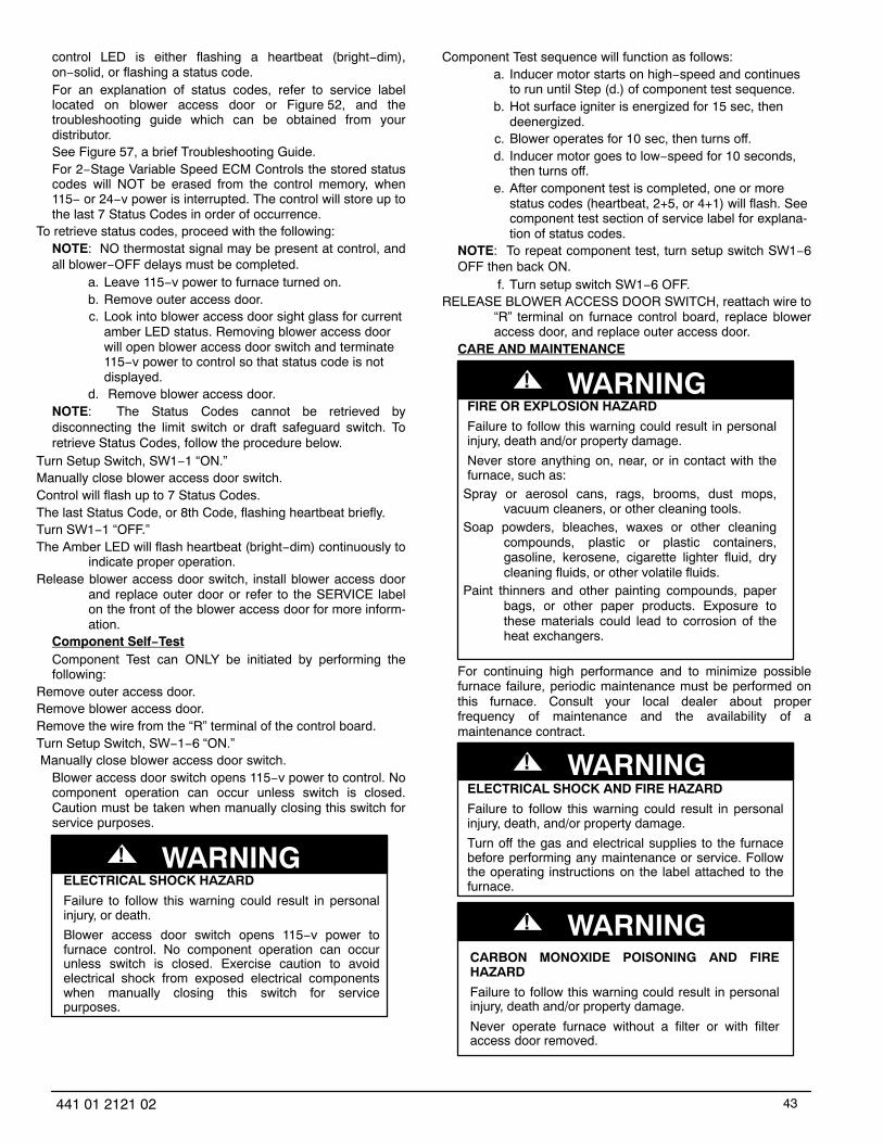
43441 01 2121 02
control LED is either flashing a heartbeat (bright−dim),on−solid, or flashing a status code.For an explanation of status codes, refer to service labellocated on blower access door or Figure 52, and thetroubleshooting guide which can be obtained from yourdistributor.See Figure 57, a brief Troubleshooting Guide.For 2−Stage Variable Speed ECM Controls the stored statuscodes will NOT be erased from the control memory, when115− or 24−v power is interrupted. The control will store up tothe last 7 Status Codes in order of occurrence.
To retrieve status codes, proceed with the following:NOTE: NO thermostat signal may be present at control, andall blower−OFF delays must be completed.
a. Leave 115−v power to furnace turned on.b. Remove outer access door.c. Look into blower access door sight glass for current
amber LED status. Removing blower access doorwill open blower access door switch and terminate115−v power to control so that status code is notdisplayed.
d. Remove blower access door.NOTE: The Status Codes cannot be retrieved bydisconnecting the limit switch or draft safeguard switch. Toretrieve Status Codes, follow the procedure below.
Turn Setup Switch, SW1−1 “ON.”Manually close blower access door switch.Control will flash up to 7 Status Codes.The last Status Code, or 8th Code, flashing heartbeat briefly.Turn SW1−1 “OFF.”The Amber LED will flash heartbeat (bright−dim) continuously to
indicate proper operation.Release blower access door switch, install blower access door
and replace outer door or refer to the SERVICE labelon the front of the blower access door for more inform-ation.
Component Self−TestComponent Test can ONLY be initiated by performing thefollowing:
Remove outer access door.Remove blower access door.Remove the wire from the “R” terminal of the control board.Turn Setup Switch, SW−1−6 “ON.” Manually close blower access door switch.
Blower access door switch opens 115−v power to control. Nocomponent operation can occur unless switch is closed.Caution must be taken when manually closing this switch forservice purposes.
ELECTRICAL SHOCK HAZARD
Failure to follow this warning could result in personalinjury, or death.
Blower access door switch opens 115−v power tofurnace control. No component operation can occurunless switch is closed. Exercise caution to avoidelectrical shock from exposed electrical componentswhen manually closing this switch for servicepurposes.
! WARNING
Component Test sequence will function as follows:a. Inducer motor starts on high−speed and continues
to run until Step (d.) of component test sequence.b. Hot surface igniter is energized for 15 sec, then
deenergized.c. Blower operates for 10 sec, then turns off.d. Inducer motor goes to low−speed for 10 seconds,
then turns off.e. After component test is completed, one or more
status codes (heartbeat, 2+5, or 4+1) will flash. Seecomponent test section of service label for explana-tion of status codes.
NOTE: To repeat component test, turn setup switch SW1−6OFF then back ON.
f. Turn setup switch SW1−6 OFF.RELEASE BLOWER ACCESS DOOR SWITCH, reattach wire to
“R” terminal on furnace control board, replace bloweraccess door, and replace outer access door.
CARE AND MAINTENANCE
FIRE OR EXPLOSION HAZARD
Failure to follow this warning could result in personalinjury, death and/or property damage.
Never store anything on, near, or in contact with thefurnace, such as:
Spray or aerosol cans, rags, brooms, dust mops,vacuum cleaners, or other cleaning tools.
Soap powders, bleaches, waxes or other cleaningcompounds, plastic or plastic containers,gasoline, kerosene, cigarette lighter fluid, drycleaning fluids, or other volatile fluids.
Paint thinners and other painting compounds, paperbags, or other paper products. Exposure tothese materials could lead to corrosion of theheat exchangers.
! WARNING
For continuing high performance and to minimize possiblefurnace failure, periodic maintenance must be performed onthis furnace. Consult your local dealer about properfrequency of maintenance and the availability of amaintenance contract.
ELECTRICAL SHOCK AND FIRE HAZARD
Failure to follow this warning could result in personalinjury, death, and/or property damage.
Turn off the gas and electrical supplies to the furnacebefore performing any maintenance or service. Followthe operating instructions on the label attached to thefurnace.
! WARNING
CARBON MONOXIDE POISONING AND FIREHAZARD
Failure to follow this warning could result in personalinjury, death and/or property damage.
Never operate furnace without a filter or with filteraccess door removed.
! WARNING
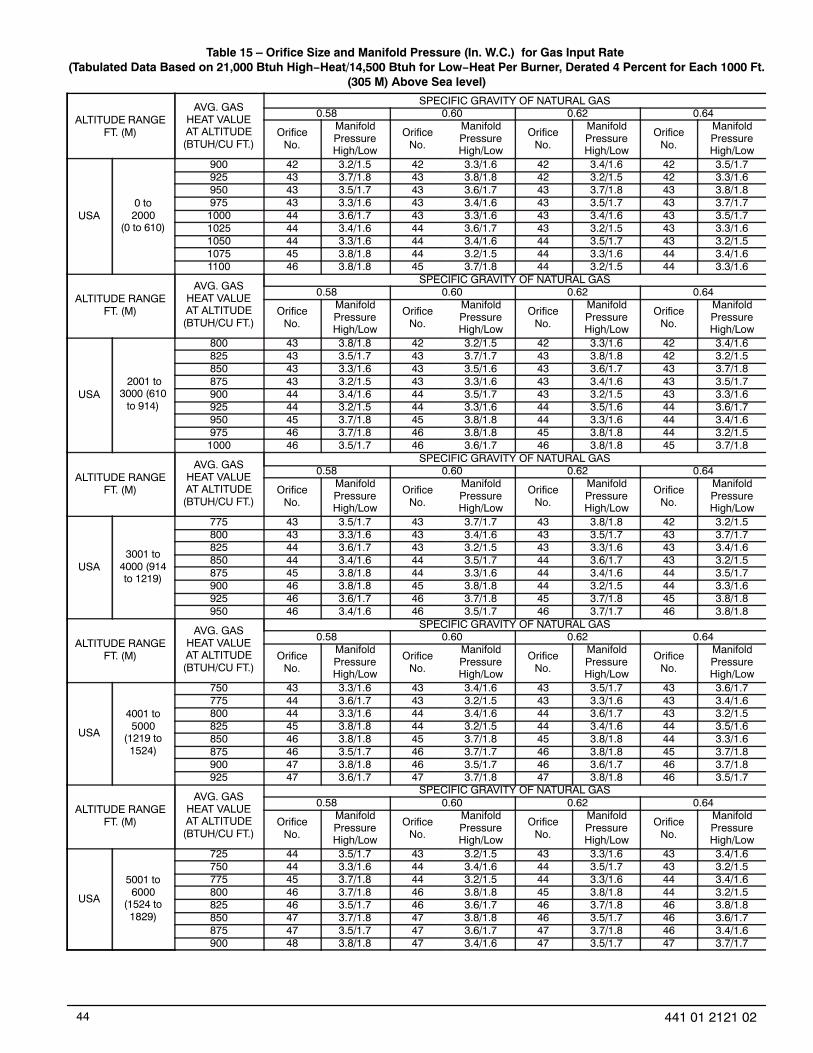
44 441 01 2121 02
Table 15 – Orifice Size and Manifold Pressure (In. W.C.) for Gas Input Rate (Tabulated Data Based on 21,000 Btuh High−Heat/14,500 Btuh for Low−Heat Per Burner, Derated 4 Percent for Each 1000 Ft.
(305 M) Above Sea level)
ALTITUDE RANGEFT. (M)
AVG. GASHEAT VALUEAT ALTITUDE(BTUH/CU FT.)
SPECIFIC GRAVITY OF NATURAL GAS0.58 0.60 0.62 0.64
OrificeNo.
ManifoldPressureHigh/Low
OrificeNo.
ManifoldPressureHigh/Low
OrificeNo.
ManifoldPressureHigh/Low
OrificeNo.
ManifoldPressureHigh/Low
USA0 to2000
(0 to 610)
900 42 3.2/1.5 42 3.3/1.6 42 3.4/1.6 42 3.5/1.7925 43 3.7/1.8 43 3.8/1.8 42 3.2/1.5 42 3.3/1.6950 43 3.5/1.7 43 3.6/1.7 43 3.7/1.8 43 3.8/1.8975 43 3.3/1.6 43 3.4/1.6 43 3.5/1.7 43 3.7/1.71000 44 3.6/1.7 43 3.3/1.6 43 3.4/1.6 43 3.5/1.71025 44 3.4/1.6 44 3.6/1.7 43 3.2/1.5 43 3.3/1.61050 44 3.3/1.6 44 3.4/1.6 44 3.5/1.7 43 3.2/1.51075 45 3.8/1.8 44 3.2/1.5 44 3.3/1.6 44 3.4/1.61100 46 3.8/1.8 45 3.7/1.8 44 3.2/1.5 44 3.3/1.6
ALTITUDE RANGEFT. (M)
AVG. GASHEAT VALUEAT ALTITUDE(BTUH/CU FT.)
SPECIFIC GRAVITY OF NATURAL GAS0.58 0.60 0.62 0.64
OrificeNo.
ManifoldPressureHigh/Low
OrificeNo.
ManifoldPressureHigh/Low
OrificeNo.
ManifoldPressureHigh/Low
OrificeNo.
ManifoldPressureHigh/Low
USA 2001 to
3000 (610to 914)
800 43 3.8/1.8 42 3.2/1.5 42 3.3/1.6 42 3.4/1.6825 43 3.5/1.7 43 3.7/1.7 43 3.8/1.8 42 3.2/1.5850 43 3.3/1.6 43 3.5/1.6 43 3.6/1.7 43 3.7/1.8875 43 3.2/1.5 43 3.3/1.6 43 3.4/1.6 43 3.5/1.7900 44 3.4/1.6 44 3.5/1.7 43 3.2/1.5 43 3.3/1.6925 44 3.2/1.5 44 3.3/1.6 44 3.5/1.6 44 3.6/1.7950 45 3.7/1.8 45 3.8/1.8 44 3.3/1.6 44 3.4/1.6975 46 3.7/1.8 46 3.8/1.8 45 3.8/1.8 44 3.2/1.51000 46 3.5/1.7 46 3.6/1.7 46 3.8/1.8 45 3.7/1.8
ALTITUDE RANGEFT. (M)
AVG. GASHEAT VALUEAT ALTITUDE(BTUH/CU FT.)
SPECIFIC GRAVITY OF NATURAL GAS0.58 0.60 0.62 0.64
OrificeNo.
ManifoldPressureHigh/Low
OrificeNo.
ManifoldPressureHigh/Low
OrificeNo.
ManifoldPressureHigh/Low
OrificeNo.
ManifoldPressureHigh/Low
USA3001 to
4000 (914to 1219)
775 43 3.5/1.7 43 3.7/1.7 43 3.8/1.8 42 3.2/1.5800 43 3.3/1.6 43 3.4/1.6 43 3.5/1.7 43 3.7/1.7825 44 3.6/1.7 43 3.2/1.5 43 3.3/1.6 43 3.4/1.6850 44 3.4/1.6 44 3.5/1.7 44 3.6/1.7 43 3.2/1.5875 45 3.8/1.8 44 3.3/1.6 44 3.4/1.6 44 3.5/1.7900 46 3.8/1.8 45 3.8/1.8 44 3.2/1.5 44 3.3/1.6925 46 3.6/1.7 46 3.7/1.8 45 3.7/1.8 45 3.8/1.8950 46 3.4/1.6 46 3.5/1.7 46 3.7/1.7 46 3.8/1.8
ALTITUDE RANGEFT. (M)
AVG. GASHEAT VALUEAT ALTITUDE(BTUH/CU FT.)
SPECIFIC GRAVITY OF NATURAL GAS0.58 0.60 0.62 0.64
OrificeNo.
ManifoldPressureHigh/Low
OrificeNo.
ManifoldPressureHigh/Low
OrificeNo.
ManifoldPressureHigh/Low
OrificeNo.
ManifoldPressureHigh/Low
USA
4001 to5000
(1219 to1524)
750 43 3.3/1.6 43 3.4/1.6 43 3.5/1.7 43 3.6/1.7775 44 3.6/1.7 43 3.2/1.5 43 3.3/1.6 43 3.4/1.6800 44 3.3/1.6 44 3.4/1.6 44 3.6/1.7 43 3.2/1.5825 45 3.8/1.8 44 3.2/1.5 44 3.4/1.6 44 3.5/1.6850 46 3.8/1.8 45 3.7/1.8 45 3.8/1.8 44 3.3/1.6875 46 3.5/1.7 46 3.7/1.7 46 3.8/1.8 45 3.7/1.8900 47 3.8/1.8 46 3.5/1.7 46 3.6/1.7 46 3.7/1.8925 47 3.6/1.7 47 3.7/1.8 47 3.8/1.8 46 3.5/1.7
ALTITUDE RANGEFT. (M)
AVG. GASHEAT VALUEAT ALTITUDE(BTUH/CU FT.)
SPECIFIC GRAVITY OF NATURAL GAS0.58 0.60 0.62 0.64
OrificeNo.
ManifoldPressureHigh/Low
OrificeNo.
ManifoldPressureHigh/Low
OrificeNo.
ManifoldPressureHigh/Low
OrificeNo.
ManifoldPressureHigh/Low
USA
5001 to6000
(1524 to1829)
725 44 3.5/1.7 43 3.2/1.5 43 3.3/1.6 43 3.4/1.6750 44 3.3/1.6 44 3.4/1.6 44 3.5/1.7 43 3.2/1.5775 45 3.7/1.8 44 3.2/1.5 44 3.3/1.6 44 3.4/1.6800 46 3.7/1.8 46 3.8/1.8 45 3.8/1.8 44 3.2/1.5825 46 3.5/1.7 46 3.6/1.7 46 3.7/1.8 46 3.8/1.8850 47 3.7/1.8 47 3.8/1.8 46 3.5/1.7 46 3.6/1.7875 47 3.5/1.7 47 3.6/1.7 47 3.7/1.8 46 3.4/1.6900 48 3.8/1.8 47 3.4/1.6 47 3.5/1.7 47 3.7/1.7

45441 01 2121 02
Table 15 − Orifice Size and Manifold Pressure (In. W.C.) for Gas Input Rate (Con’t.)(Tabulated Data Based on 21,000 Btuh High−Heat/14,500 Btuh for Low−Heat Per Burner, Derated 4 Percent for Each 1000
Ft. (305 M) Above Sea level)
ALTITUDE RANGEFT. (M)
AVG. GASHEAT VALUEAT ALTITUDE(BTUH/CU FT.)
SPECIFIC GRAVITY OF NATURAL GAS0.58 0.60 0.62 0.64
OrificeNo.
ManifoldPressureHigh/Low
OrificeNo.
ManifoldPressureHigh/Low
OrificeNo.
ManifoldPressureHigh/Low
OrificeNo.
ManifoldPressureHigh/Low
USA
6001 to7000
(1829 to2134)
675 44 3.5/1.7 43 3.2/1.5 43 3.3/1.6 43 3.4/1.6700 44 3.3/1.6 44 3.4/1.6 44 3.5/1.7 43 3.2/1.5725 45 3.7/1.8 45 3.8/1.8 44 3.3/1.6 44 3.4/1.6750 46 3.6/1.7 46 3.8/1.8 45 3.7/1.8 45 3.8/1.8775 46 3.4/1.6 46 3.5/1.7 46 3.6/1.7 46 3.8/1.8800 47 3.6/1.7 47 3.8/1.8 46 3.4/1.6 46 3.5/1.7825 47 3.4/1.6 47 3.5/1.7 47 3.6/1.7 47 3.8/1.8850 48 3.7/1.7 48 3.8/1.8 47 3.4/1.6 47 3.5/1.7
ALTITUDE RANGEFT. (M)
AVG. GASHEAT VALUEAT ALTITUDE(BTUH/CU FT.)
SPECIFIC GRAVITY OF NATURAL GAS0.58 0.60 0.62 0.64
OrificeNo.
ManifoldPressureHigh/Low
OrificeNo.
ManifoldPressureHigh/Low
OrificeNo.
ManifoldPressureHigh/Low
OrificeNo.
ManifoldPressureHigh/Low
USA
7001 to8000
(2134 to2438)
650 44 3.3/1.6 44 3.4/1.6 44 3.5/1.7 43 3.2/1.5675 45 3.7/1.8 45 3.8/1.8 44 3.3/1.6 44 3.4/1.6700 46 3.6/1.7 46 3.7/1.8 46 3.8/1.8 45 3.8/1.8725 47 3.8/1.8 46 3.5/1.7 46 3.6/1.7 46 3.7/1.8750 47 3.5/1.7 47 3.7/1.8 47 3.8/1.8 46 3.5/1.6775 48 3.8/1.8 47 3.4/1.6 47 3.6/1.7 47 3.7/1.7800 48 3.6/1.7 48 3.7/1.8 48 3.8/1.8 47 3.4/1.6825 48 3.3/1.6 48 3.5/1.6 48 3.6/1.7 48 3.7/1.8
ALTITUDE RANGEFT. (M)
AVG. GASHEAT VALUEAT ALTITUDE(BTUH/CU FT.)
SPECIFIC GRAVITY OF NATURAL GAS0.58 0.60 0.62 0.64
OrificeNo.
ManifoldPressureHigh/Low
OrificeNo.
ManifoldPressureHigh/Low
OrificeNo.
ManifoldPressureHigh/Low
OrificeNo.
ManifoldPressureHigh/Low
USA
8001 to9000
(2438 to2743)
625 45 3.7/1.8 45 3.8/1.8 44 3.3/1.6 44 3.4/1.6650 46 3.6/1.7 46 3.7/1.8 46 3.8/1.8 45 3.8/1.8675 47 3.8/1.8 46 3.4/1.6 46 3.5/1.7 46 3.7/1.7700 47 3.5/1.7 47 3.6/1.7 47 3.7/1.8 46 3.4/1.6725 48 3.7/1.8 48 3.8/1.8 47 3.5/1.7 47 3.6/1.7750 48 3.5/1.7 48 3.6/1.7 48 3.7/1.8 48 3.8/1.8775 49 3.8/1.8 48 3.4/1.6 48 3.5/1.7 48 3.6/1.7
ALTITUDE RANGEFT. (M)
AVG. GASHEAT VALUEAT ALTITUDE(BTUH/CU FT.)
SPECIFIC GRAVITY OF NATURAL GAS0.58 0.60 0.62 0.64
OrificeNo.
ManifoldPressureHigh/Low
OrificeNo.
ManifoldPressureHigh/Low
OrificeNo.
ManifoldPressureHigh/Low
OrificeNo.
ManifoldPressureHigh/Low
USA
9001 to10,000
(2743 to3048)
600 46 3.6/1.7 46 3.7/1.8 46 3.8/1.8 45 3.7/1.8625 47 3.7/1.8 47 3.8/1.8 46 3.5/1.7 46 3.6/1.7650 47 3.4/1.6 47 3.6/1.7 47 3.7/1.8 47 3.8/1.8675 48 3.6/1.7 48 3.8/1.8 47 3.4/1.6 47 3.5/1.7700 48 3.4/1.6 48 3.5/1.7 48 3.6/1.7 48 3.7/1.8725 49 3.7/1.8 49 3.8/1.8 48 3.4/1.6 48 3.5/1.7
* Orifice numbers 43 are factory installed
CUT HAZARD
Failure to follow this caution may result in personalinjury.
Sheet metal parts may have sharp edges or burrs. Usecare and wear appropriate protective clothing, safetyglasses and gloves when handling parts, and servicingfurnaces.
CAUTION!
The minimum maintenance on this furnace is as follows:Check and clean air filter each month or more frequently if re-
quired. Replace if torn.Check blower motor and wheel for cleanliness each heating and
cooling season. Clean as necessary.Check electrical connections for tightness and controls for prop-
er operation each heating season. Service as neces-sary.
Inspect burner compartment before each heating season forrust, corrosion, soot or excessive dust. If necessary,have furnace and burner serviced by a qualified ser-vice agency.
Inspect the vent pipe/vent system before each heating seasonfor rust, corrosion, water leakage, sagging pipes orbroken fittings. Have vent pipes/vent system servicedby a qualified service agency.
Inspect any accessories attached to the furnace such as a hu-midifier or electronic air cleaner. Perform any service ormaintenance to the accessories as recommended inthe accessory instructions.

46 441 01 2121 02
Table 16 – Filter Size Information − In. (mm)
FURNACE CASING WIDTHFILTER SIZE
FILTER TYPESIDE RETURN
BOTTOM RETURN
14−1/2 (368)16 X 25 X 3/4
(406 X 635 X 19)14 X 25 X 3/4
(356 X 635 X 19) Washable*
17−1/2 (445)16 X 25 X 3/4
(406 X 635 X 19)16 X 25 X 3/4
(406 X 635 X 19) Washable*
21 (533)16 X 25 X 3/4
(406 X 635 X 19)20 X 25 X 3/4
(508 X 635 X 19) Washable*
24 (610)16 X 25 X 3/4
(406 X 635 X 19)24 X 25 X 3/4
(610 X 635 X 19) Washable*
* RecommendedCleaning and/or Replacing Air FilterThe air filter arrangement will vary depending on theapplication.NOTE: If the filter has an airflow direction arrow, the arrowmust point towards the blower.
CUT HAZARD
Failure to follow this caution may result in personalinjury.
Sheet metal parts may have sharp edges or burrs. Usecare and wear appropriate protective clothing, safetyglasses and gloves when handling parts, and servicingfurnaces.
CAUTION!
Blower Motor and Wheel
ELECTRICAL SHOCK HAZARD
Failure to follow this warning could result in personalinjury or death.
Blower access door switch opens 115−v power tocontrol. No component operation can occur unlessswitch is closed. Caution must be taken whenmanually closing this switch for service purposes.
! WARNING
NOTE: The blower wheel should not be dropped or bent asbalance will be affected.The following steps should be performed by a qualifiedservice agency.To ensure long life and high efficiency, clean accumulated dirtand grease from blower wheel and motor annually.The inducer and blower motors are pre−lubricated andrequire no additional lubrication. These motors can beidentified by the absence of oil ports on each end of themotor.Clean blower motor and wheel as follows:
Turn off electrical supply to furnace.Remove outer door.For downflow or horizontal furnaces having vent pipes within the
furnace that pass in front of the blower access door:a. Disconnect vent connector from furnace vent elbow.b. Disconnect and remove short piece of vent pipe
from within furnace.Remove 2 screws from blower access door and remove blower
access door.All factory wires can be left connected, but field thermostat con-
nections may need to be disconnected depending ontheir length and routing.
Remove 2 screws holding blower assembly to blower deck andslide blower assembly out of furnace.
Clean blower wheel and motor using a vacuum with soft brushattachment. Blower wheel blades may be cleaned witha small paint or flux brush. Do not remove or disturbbalance weights (clips) on blower wheel blades.
Vacuum any loose dust from blower housing, wheel and motor.If a greasy residue is present on blower wheel, remove wheel
from the blower housing and wash it with an appropri-ate degreaser. To remove wheel:
NOTE: Before disassembly, mark blower mounting arms,motor, and blower housing so motor and each arm ispositioned at the same location during reassembly.
a. Disconnect ground wire attached to blower housing.b. Remove screws securing cutoff plate and remove
cutoff plate from housing.c. Loosen set screw holding blower wheel on motor
shaft (160+/−20 in.−lb. when assembling).d. Remove bolts holding motor to blower housing and
slide motor out of wheel (40+/−10 in.−lb. when reas-sembling).
e. Remove blower wheel from housing.f. Clean wheel and housing.
Reassemble motor and blower by reversing steps 9a, through9e. Be sure to reattach ground wire to the blower hous-ing.
Verify that blower wheel is centered in blower housing and setscrew contacts the flat portion of the motor shaft.Loosen set screw on blower wheel and reposition if ne-cessary.
Spin the blower wheel by hand to verify that the wheel does notrub on the housing.
Reinstall blower assembly in furnace.Reinstall 2 screws securing blower assembly to blower deck.Reconnect blower leads to furnace control. Refer to furnace wir-
ing diagram, and connect thermostat leads if previouslydisconnected.
To check blower for proper rotation:a. Turn on electrical supply.
ELECTRICAL SHOCK HAZARD
Failure to follow this warning could result in personalinjury, or death.
Blower access door switch opens 115−v power tofurnace control. No component operation can occurunless switch is closed. Exercise caution to avoidelectrical shock from exposed electrical componentswhen manually closing this switch for service purposes.
! WARNING
b. Manually close blower access door switch.

47441 01 2121 02
NOTE: If R−W/W1 thermostat terminals are jumpered at thetime blower access door switch is closed, blower will run for90 sec before beginning a heating cycle.
c. Perform component self−test as shown at the bot-tom of the SERVICE label, located on the front ofblower access door.
d. Verify blower is rotating in the correct directionIf furnace is operating properly, RELEASE BLOWER ACCESS
DOOR SWITCH. Remove any jumpers or reconnectany disconnected thermostat leads. Replace bloweraccess door.
Downflow or horizontal furnaces with vent pipe through furnaceonly:a. Install and connect short piece of vent pipe inside
furnace to existing vent.b. Connect vent connector to vent elbow.
Reinstall outer door.Turn on gas supply and cycle furnace through one complete
heating and cooling cycle. Verify the furnace temperat-ure rise as shown in Adjustments Section. Adjust tem-perature rise as shown in Adjustments Section. If out-door temperature is below 70�F, turn off circuit breakerto outdoor unit before running furnace in the coolingcycle. Turn outdoor circuit breaker on after completingcooling cycle.
Cleaning Heat ExchangerThe following steps should be performed by a qualifiedservice agency:NOTE: If the heat exchangers get a heavy accumulation ofsoot and carbon, they should be replaced rather than trying toclean them thoroughly. A build−up of soot and carbonindicates that a problem exists which needs to be corrected,such as improper adjustment of manifold pressure,insufficient or poor quality combustion air, incorrect size ordamaged manifold orifice(s), improper gas, or a restrictedheat exchanger. Action must be taken to correct the problem.
If it becomes necessary to clean the heat exchangersbecause of dust or corrosion, proceed as follows:
Turn OFF gas and electrical power to furnace.Remove outer access door.Disconnect vent connector from furnace vent elbow. For downflow or horizontal furnace having an internal vent pipe,
remove internal vent pipe within the casing. Disconnect wires to the following components. Mark wires to
aid in reconnection (be careful when disconnectingwires from switches because damage may occur):a. Draft safeguard switch.b. Inducer motor.c. Pressure switches.d. Limit overtemperature switch.e. Gas valve.f. Hot surface igniter.
g. Flame−sensing electrode.h. Flame rollout switches.
Remove screws that fasten the collector box assembly to thecell panel. Be careful not to damage the collector box.Inducer assembly and elbow need not be removedfrom collector box.
Disconnect gas line from gas manifold.Remove the four screws that attach the burner assembly to the
cell panel. The gas valve and individual burners need
not be removed from support assembly. Remove NOxbaffles, if installed.
NOTE: Be very careful when removing burner assembly toavoid breaking igniter. See Figure 53−Figure 54 for correctigniter location.
Using field−provided 25−caliber rifle cleaning brush, 36−in. (914mm) long, 1/4−in. (6 mm) diameter steel spring cable, avariable speed reversible electric drill, and vacuumcleaner, clean cells as follows:
Figure 53 − Igniter Position − Side View
A05025
Figure 54 − Igniter Position − Top View
A05026
a. Remove metal screw fitting from wire brush to allowinsertion into cable.
b. Insert the twisted wire end of brush into end ofspring cable, and crimp tight with crimping tool orcrimp by striking with ball−peen hammer. TIGHT-NESS IS VERY IMPORTANT.
NOTE: The materials needed in item 9 can usually bepurchased at local hardware stores.
(1.) Attach variable−speed, reversible drill to theend of spring cable (end opposite brush).
(2.) Insert brush end of cable into the outlet open-ing of cell and slowly rotate with drill. DO NOTforce cable. Gradually insert cable into upperpass of cell. (See Figure 51)
(3.) Work cable in and out of cell 3 or 4 times toobtain sufficient cleaning. DO NOT pull cablewith great force. Reverse drill and graduallywork cable out.
(4.) Insert brush end of cable in burner inlet open-ing of cell, and proceed to clean 2 lowerpasses of cell in same manner as upper pass.
(5.) Repeat foregoing procedures until each cell infurnace has been cleaned.

48 441 01 2121 02
(6.) Using vacuum cleaner, remove residue fromeach cell.
(7.) Using vacuum cleaner with soft brush attach-ment, clean burner assembly.
(8.) Clean flame sensor with fine steel wool.(9.) Install NOx baffles (if removed).
Figure 55 − Cleaning Heat Exchanger Cell
A91252
(10.) Reinstall burner assembly. Center burners incell openings.
Remove old sealant from cell panel and collector box flange.Spray releasing agent on the heat exchanger cell panel where
collector box assembly contacts cell panel.NOTE: A releasing agent such as a vegetable oil cookingspray that does not contain corn oil, canola oil, halogenatedhydrocarbons or aromatic content, which may prevent aninadequate seal from occuring, and RTV sealant such asG.E. RTV 162, G.E. RTV 6702, or Dow−Corning RTV 738sealant are required. DO NOT substitute any other type ofRTV sealant.
Apply new sealant to flange of collector box and attach to cellpanel using existing screws, making sure all screwsare secure.
Reconnect wires to the following components (Use connectiondiagram on wiring label, if wires were not marked forreconnection locations.):a. Draft safeguard switch.b. Inducer motor.c. Pressure switches.d. Limit overtemperature switch.e. Gas valve.f. Hot surface igniter.
g. Flame−sensing electrode.h. Flame rollout switches.
Reinstall internal vent pipe, if applicable.Reinstall vent connector on furnace vent elbow. Securely fasten
vent connector to vent elbow with 2 field−supplied, cor-rosion−resistant, sheet metal screws located 180�apart.
Replace blower access door only if it was removed.Set thermostat above room temperature and check furnace for
proper operation.Verify blower airflow and speed changes between heating and
cooling.Check for gas leaks.
FIRE OR EXPLOSION HAZARD
Failure to follow this warning could result in personalinjury, death, and/or property damage.
Never purge a gas line into a combustion chamber.Never test for gas leaks with an open flame. Use acommercially available soap solution madespecifically for the detection of leaks to check allconnections. A fire or explosion may result causingproperty damage, personal injury or loss of life.
! WARNING
Sequence of OperationNOTE: Furnace control must be grounded for properoperation or else control will lock out. Control is groundedthrough green/yellow wire routed to gas valve and burner boxscrew. Using the schematic diagram in Figure 56, follow thesequence of operation through the different modes. Read andfollow the wiring diagram very carefully.NOTE: If a power interruption occurs during a call for heat(W/W1 or W/W1−and−W2), the control will start a 90−secondblower−only ON period two seconds after power is restored, ifthe thermostat is still calling for gas heating. The amber LEDlight will flash code 1+2 during the 90−second period, afterwhich the LED will flash a heartbeat (bright−dim), as long asno faults are detected. After the 90−second period, thefurnace will respond to the thermostat normally.The blower door must be installed for power to be conductedthrough the blower door interlock switch ILK to the furnacecontrol CPU, transformer TRAN, inducer motor IDM, blowermotor BLWM, hot−surface igniter HSI, and gas valve GV.
Two−Stage Heating (Adaptive Mode) with Single−StageThermostat See Figure 25 thermostat connections
NOTE: The low−heat only switch SW1−2 selects either thelow−heat only operation mode when ON, (see item 2. below)or the adaptive heating mode when OFF in response to a callfor heat. (See Table 9) When the W2 thermostat terminal isenergized it will always cause high−heat operation when theR−to−W circuit is closed, regardless of the setting of thelow−heat only switch. This furnace can operate as atwo−stage furnace with a single−stage thermostat becausethe furnace control CPU includes a programmed adaptivesequence of controlled operation, which selects low−heat orhigh−heat operation. This selection is based upon the storedhistory of the length of previous gas−heating periods of thesingle−stage thermostat.The furnace will start up in either low− or high−heat. If thefurnace starts up in low−heat, the control CPU determines thelow−heat on−time (from 0 to 16 minutes) which is permittedbefore switching to high−heat.If the power is interrupted, the stored history is erased andthe control CPU will select low−heat for up to 16 minutes andthen switch to high−heat, as long as the thermostat continuesto call for heat. Subsequent selection is based on storedhistory of the thermostat cycle times.The wall thermostat “calls for heat”, closing the R−to−Wcircuit. The furnace control performs a self−check, verifies thelow−heat and high−heat pressure switch contacts LPS andHPS are open, and starts the inducer motor IDM inhigh−speed.
a. Inducer Prepurge Period(1.) If the furnace control CPU selects low−heat
operation the inducer motor IDM comes up tospeed, the low−heat pressure switch LPS

49441 01 2121 02
closes, and the furnace control CPU begins a15−second prepurge period. If the low−heatpressure switch LPS fails to remain closed theinducer motor IDM will remain running at high−speed. After the low−heat pressure switch re−closes the furnace control CPU will begin a15−second prepurge period, and continue torun the inducer motor IDM at high−speed.
(2.) If the furnace control CPU selects high−heatoperation, the inducer motor IDM remains run-ning at high−speed, and the high−heat pres-sure switch relay HPSR is de−energized toclose the NC contact. When sufficient pressureis available the high−heat pressure switch HPScloses, and the high−heat gas valve solenoidGV−HI is energized. The furnace control CPUbegins a 15−second prepurge period after thelow−heat pressure switch LPS closes. If thehigh−heat pressure switch HPS fails to closeand the low−heat pressure switch LPS closes,the furnace will operate at low−heat gas flowrate until the high−heat pressure switch closesfor a maximum of 2 minutes after ignition.
b. Igniter Warm−Up −At the end of the prepurge peri-od, the Hot−Surface Igniter HSI is energized for a17−second igniter warm−up period.
c. Trial−For−Ignition Sequence −When the igniterwarm−up period is completed the main gas valverelay contact GVR closes to energize the gas valvesolenoid GV−M. The gas valve solenoid GV−M per-mits gas flow to the burners where it is ignited bythe HSI. Five seconds after the GVR closes, a2−second flame proving period begins. The HSIigniter will remain energized until the flame issensed or until the 2−second flame proving periodbegins. If the furnace control CPU selects high−heat operation, the high−heat gas valve solenoidGV−HI is also energized.
d. Flame−Proving − When the burner flame is provedat the flame−proving sensor electrode FSE, the in-ducer motor IDM switches to low−speed unless thefurnace is operating in high−heat, and the furnacecontrol CPU begins the blower−ON delay periodand continues to hold the gas valve GV−M open. Ifthe burner flame is not proved within two seconds,the control CPU will close the gas valve GV−M, andthe control CPU will repeat the ignition sequence forup to three more Trials−For−Ignition before going toIgnition−Lockout. Lockout will be reset automaticallyafter three hours, or by momentarily interrupting 115vac power to the furnace, or by interrupting 24 vacpower at SEC1 or SEC2 to the furnace control CPU(not at W/W1, G, R, etc.). If flame is proved whenflame should not be present, the furnace controlCPU will lock out of Gas−Heating mode and oper-ate the inducer motor IDM on high speed until flameis no longer proved.
e. Blower−On delay − If the burner flame is proventhe blower−ON delays for low−heat and high−heatare as follows: Low−heat − 45 seconds after the gas valve GV−Mis opened the blower motor BLWM is turned ON atlow−heat airflow. High−heat − 25 seconds after the gas valve GV−Mis opened the BLWM is turned ON at high−heatairflow. Simultaneously, the humidifier terminal HUMand electronic air cleaner terminal EAC−1 are ener-gized and remain energized throughout the heatingcycle.
f. Switching from Low− to High−Heat − If the fur-nace control CPU switches from low−heat to high−
heat, the furnace control CPU will switch the in-ducer motor IDM speed from low to high. Thehigh−heat pressure switch relay HPSR is de−ener-gized to close the NC contact. When sufficient pres-sure is available the high−heat pressure switchHPS closes, and the high−heat gas valve solenoidGV−HI is energized. The blower motor BLWM willtransition to high−heat airflow five seconds after thefurnace control CPU switches from low−heat tohigh−heat.
g. Switching from High− to Low−Heat −The furnacecontrol CPU will not switch from high−heat to low−heat while the thermostat R−to−W circuit is closedwhen using a single−stage thermostat.
h. Blower−Off Delay −When the thermostat is satis-fied, the R to W circuit is opened, de−energizing thegas valve GV−M, stopping gas flow to the burners,and de−energizing the humidifier terminal HUM.The inducer motor IDM will remain energized for a5−second post−purge period. The blower motorBLWM and air cleaner terminal EAC−1 will remainenergized at low−heat airflow or transition to low−heat airflow for 90, 120, 150, or 180 seconds (de-pending on selection at blower−OFF delayswitches). The furnace control CPU is factory−setfor a 120−second blower−OFF delay.
Two−Stage Thermostat and Two−Stage Heating See Figure 27−Figure 33 for thermostat connections.
NOTE: In this mode the low−heat only switch SW1−2 mustbe ON to select the low−heat only operation mode inresponse to closing the thermostat R−to−W1 circuit. Closingthe thermostat R−to− W1−and−W2 circuits always causeshigh−heat operation, regardless of the setting of the low−heatonly switch.The wall thermostat “calls for heat”, closing the R−to−W1circuit for low−heat or closing the R−to−W1−and−W2 circuitsfor high−heat. The furnace control performs a self−check,verifies the low−heat and high−heat pressure switch contactsLPS and HPS are open, and starts the inducer motor IDM inhigh−speed.The start up and shut down functions and delays described initem 1. above apply to the 2−stage heating mode as well,except for switching from low− to high−Heat and vice versa.
a. Switching from Low− to High−Heat − If the ther-mostat R−to−W1 circuit is closed and the R−to−W2circuit closes, the furnace control CPU will switchthe inducer motor IDM speed from low to high. Thehigh−heat pressure switch relay HPSR is de−ener-gized to close the NC contact. When sufficient pres-sure is available the high−heat pressure switchHPS closes, and the high−heat gas valve solenoidGV−HI is energized. The blower motor BLWM willtransition to high−heat airflow five seconds after theR−to−W2 circuit closes.
b. Switching from High− to Low−Heat −If the ther-mostat R−to− W2 circuit opens, and the R−to−W1circuit remains closed, the furnace control CPU willswitch the inducer motor IDM speed from high tolow. The high−heat pressure switch relay HPSR isenergized to open the NC contact and de−energizethe high−heat gas valve solenoid GV−HI. When theinducer motor IDM reduces pressure sufficiently, thehigh−heat pressure switch HPS will open. The gasvalve solenoid GV−M will remain energized as longas the low−heat pressure switch LPS remainsclosed. The blower motor BLWM will transition tolow−heat airflow five seconds after the R−to−W2circuit opens.
Cooling modeThe thermostat “calls for cooling”.a. Single−Speed Cooling−
See Figure 27 for thermostat connections

50 441 01 2121 02
The thermostat closes the R−to−G−and−Y circuits.The R−to− Y circuit starts the outdoor unit, and theR−to−G−and−Y/Y2 circuits start the furnace blowermotor BLWM on cooling airflow. Cooling airflow isbased on the A/C selection shown in Figure 51. Theelectronic air cleaner terminal EAC−1 is energizedwith 115 vac when the blower motor BLWM is oper-ating. When the thermostat is satisfied, the R−to−G−and−Y circuits are opened. The outdoor unit willstop, and the furnace blower motor BLWM will con-tinue operating at cooling airflow for an additional90 seconds. Jumper Y/Y2 to DHUM to reduce thecooling off−delay to 5 seconds. (See Figure 26)
b. Two−Stage Thermostat and Two−Speed Cooling See Figure 28 for thermostat connections
The thermostat closes the R−to−G−and−Y1 circuits forlow−cooling or closes the R−to−G−and−Y1−and−Y2 circuitsfor high−cooling. The R−to−Y1 circuit starts the outdoor uniton low−cooling speed, and the R−to−G−and−Y1 circuit startsthe furnace blower motor BLWM at low−cooling airflow whichis the CF (continuous fan) selection as shown in Figure 54.The R−to−Y1−and−Y2 circuits start the outdoor unit onhigh−cooling speed, and the R−to− G−and−Y/Y2 circuits startthe furnace blower motor BLWM at high−cooling airflow.High−cooling airflow is based on the A/C (air conditioning)selection shown in Figure 51. The electronic air cleaner terminal EAC−1 is energized with115 vac whenever the blower motor BLWM is operating. When the thermostat is satisfied, the R−to−G−and−Y1 orR−to− G−and−Y1−and−Y2 circuits are opened. The outdoorunit stops, and the furnace blower BLWM and electronic aircleaner terminal EAC−1 will remain energized for anadditional 90 seconds. Jumper Y1 to DHUM to reduce thecooling off−delay to 5 seconds. (See Figure 26)
Dehumidfy Mode See Figure 27−Figure 33 for thermostat connections. The H output on the humidify sensing thermostatshould be connected to the furnace control thermostatterminal DHUM. When there is a dehumidify demand,the DHUM input is activated, which means 24 vac sig-nal is removed from the DHUM input terminal. In otherwords, the DHUM input logic is reversed. The DHUMinput is turned ON when no dehumidify demand exists.Activation/DeactivationOnce 24 vac is detected by the furnace control on theDHUM input, the furnace control operates in dehumidi-fy mode. If the DHUM input is low for more than 48hours, the furnace control reverts back to non−dehu-midify mode. The cooling operation described in item 3. above alsoapplies to operation with a humidity sensing thermo-stat. The exceptions are listed below:a. Low Cooling−When the R−to−G−and−Y1 circuit is
closed and there is a demand for dehumidification,the furnace blower motor BLWM will drop theblower airflow to 86 percent of low−cooling airflowwhich is the CF (continuous fan) selection asshown in Figure 51.
b. High−Cooling−When the R−to−G−and−Y/Y2 circuitis closed and there is a demand for dehumidifica-tion, the furnace blower motor BLWM will drop theblower airflow to 86 percent of high−cooling airflow.High−cooling airflow is based on the A/C (air condi-tioning) selection shown in Figure 51.
c. Cooling off−delay−When the “call for cooling” issatisfied and there is a demand for dehumidifica-tion, the cooling blower−off delay is decreased from90 seconds to 5 seconds.
Continuous Blower Mode When the R−to−G circuit is closed by the thermostat,
the blower motor BLWM will operate at continuousblower airflow. Continuous blower airflow selection isinitially based on the CF (continuous fan) selectionshown in Figure 51. Factory default is shown inFigure 51. Terminal EAC−1 is energized as long as theblower motor BLWM is energized. During a call for heat, the furnace control CPU willtransition the blower motor BLWM to continuous blowerairflow, low−heat airflow, or the mid−range airflow,whichever is lowest. The blower motor BLWM will re-main ON until the main burners ignite then shut OFFand remain OFF for the blower−ON delay (45 secondsin low−heat, and 25 seconds in high−heat), allowingthe furnace heat exchangers to heat up more quickly,then restarts at the end of the blower−ON delay periodat low−heat or high−heat airflow, respectively. The blower motor BLWM will revert to continuous−blower airflow after the heating cycle is completed. Inhigh−heat, the furnace control CPU will drop the blowermotor BLWM to low−heat airflow during the selectedblower−OFF delay period before transitioning to con-tinuous−blower airflow. When the thermostat “calls for low−cooling”, the blowermotor BLWM will switch to operate at low−cooling air-flow. When the thermostat is satisfied, the blower motorBLWM will operate an additional 90 seconds at low−cooling airflow before transitioning back to continuous−blower airflow. When the thermostat “calls for high−cooling”, theblower motor BLWM will operate at high cooling airflow.When the thermostat is satisfied, the blower motor BL-WM will operate an additional 90 seconds at high−cool-ing airflow before transitioning back to continuous−blower airflow. When the R−to−G circuit is opened, theblower motor BLWM will continue operating for an addi-tional 5 seconds, if no other function requires blowermotor BLWM operation.
NOTE: If the blower−off delay is set to the maximum, theadjustable continuous−fan feature is locked (i.e., fan speedcannot be changed from its current setting).
Heat pumpSee Figure 29 − Figure 33 for thermostat connections.When installed with a heat pump, the furnace controlautomatically changes the timing sequence to avoidlong blower off times during demand defrost cycles.Whenever W/W1 is energized along with Y1 or Y/Y2,the furnace control CPU will transition to or bring on theblower motor BLWM at cooling airflow, low−heat airflow,or the mid−range airflow, whichever is lowest. Theblower motor BLWM will remain on until the main burn-ers ignite then shut OFF and remain OFF for 25seconds before coming back on at heating airflow.When the W/W1 input signal disappears, the furnacecontrol begins a normal inducer post−purge periodwhile changing the blower airflow. If Y/Y2 input is stillenergized the furnace control CPU will transition theblower motor BLWM airflow to cooling airflow. If Y/Y2input signal disappears and the Y1 input is still ener-gized the furnace control CPU will transition the blowermotor BLWM to low−cooling airflow. If both the Y1 andY/Y2 signals disappear at the same time, the blowermotor BLWM will remain on at low−heat airflow for theselected blower−OFF delay period. At the end of theblower− OFF delay, the blower motor BLWM will shutOFF unless G is still energized, in which case theblower motor BLWM will operate at continuous blowerairflow.
Component test The furnace features a component test system to helpdiagnose a system problem in the case of a compon-

51441 01 2121 02
ent failure. To initiate the component test procedure,ensure that there are no thermostat inputs to the con-trol and all time delays have expired. Turn on setupswitch SW1−6. (See Figure 26)
NOTE: The component test feature will not operate if thecontrol is receiving any thermostat signals or until all timedelays have expired. The component test sequence is as follows:
a. The furnace control CPU turns the inducer motorON at high−heat speed and keeps it ON throughstep c.
b. After waiting 10 seconds the furnace control CPUturns the hot surface igniter ON for 15 seconds,then OFF.
c. The furnace control CPU then turns the blower mo-tor BLWM on at mid−range airflow for 15 seconds,then OFF.
d. After shutting the blower motor OFF the furnacecontrol CPU switches the inducer to low−heatspeed for 10 seconds, then OFF.
NOTE: The EAC terminals are energized when the blower isoperating. After the component test is completed, 1 or more statuscodes (heartbeat, 2+5, or 4+1) will flash. See component testsection or Service Label (Figure 52) for explanation of statuscodes.NOTE: To repeat component test, turn setup switch SW1−6to OFF and then back ON.Wiring DiagramRefer to wiring diagram Figure 56.TroubleshootingRefer to the service label. (See Figure 52—Service Label)The Troubleshooting Guide (See Figure 57) can be a usefultool in isolating furnace operation problems. Beginning withthe word “Start,” answer each question and follow theappropriate arrow to the next item.The Guide will help to identify the problem or failedcomponent. After replacing any component, verify correctoperation sequence.

52 441 01 2121 02
Figure 56 − Wiring Diagram

53441 01 2121 02
Figure 57 − Troubleshooting Guide − Variable Speed

54 441 01 2121 02
NO
TE
:N
UM
BE
R IN
UP
PE
R L
EF
T H
AN
DC
OR
NE
R R
EP
RE
SE
NT
S F
LA
SH
CO
DE

55441 01 2121 02
NO
TE
:N
UM
BE
R IN
UP
PE
R L
EF
T H
AN
DC
OR
NE
R R
EP
RE
SE
NT
S F
LA
SH
CO
DE

56 Specifications are subject to change without notice 441 01 2121 02
PARTS REPLACEMENT INFORMATION GUIDE
CASING GROUP
Outer doorBlower doorTop filler plateBottom filler plateBottom enclosureELECTRICAL GROUP
Control bracketJunction boxLimit switch(es)Circuit boardDoor switchTransformerWiring harness 115vWiring harness 24v
BLOWER GROUP
Blower housingBlower cutoffBlower motorBlower wheelCapacitor (where used)Capacitor strap (where used)GrommetPower choke (where used)GAS CONTROL GROUP
ManifoldBurner assemblyOrificeFlame sensorHot surface igniter
Gas valve
Manual reset limit switches
HEAT EXCHANGER GROUP
Heat exchanger cell
Cell panel
Lox NOx baffle (California models only)
INDUCER GROUP
Housing assembly
Pressure switch
Inducer motor
Inducer wheel
Vent elbow assembly
MODEL NUMBER IDENTIFICATION GUIDEDIGIT POSITION 1 2 3 4 5 6,7,8 9,10 11,12 13 14
F or G= Mainline F 8 M V L 045 14 12 A 1N = Entry
8 = 80% AFUE EFFICIENCY
M = Multiposition POSITIONV = Variable Speed Blower Motor − ECM X = ECM Blower Motor S = Single−stage T = Two−stage TYPEN = Standard L = Low Nox FEATURE045 = 45,000 BTU/hr 070 = 70,000 BTU/hr 090 = 90,000 BTU/hr 110 = 110,000 BTU/hr 135 = 135,000 BTU/hr HEAT INPUT14 = 143/16”17 = 171/2”21 = 21”24 = 241/2” CABINET WIDTH08 = 800 CFM 12 = 1200 CFM 14 = 1400 CFM 16 = 1600 CFM 20 = 2000 CFM 22 = 2200 CFM COOLING AIRFLOW
SALES (MAJOR) REVISION DIGIT
ENGINEERING (MINOR) REVISION DIGIT
TO OBTAIN INFORMATION ON PARTS: Consult your installing dealer or the classified section of your local telephone directory under the “Heating Equipment“or “Air Conditioning Contractors and Systems” headings for dealer listing by brand name, or contact:
Consumer Relations DepartmentP.O. Box 128
Lewisburg, TN 37091 USA931−270−4100
Have available the product/model number and the serial number located on the unit rating plate to ensure correct replacement parts.WARNING: Improper installation, adjustment, alteration, service, or maintenance can cause personal injury, property damage, or death. Consult a qualifiedinstaller, service agency, or your local gas supplier for information or assistance. The qualified installer or service agency must use only factory−authorizedreplacement parts, kits, or accessories when modifying this product.
Copyright 2013 International Comfort ProductsLewisburg, TN 37091 USA