720 Series II pH & ORP - Myron L Company · 720 series ii ph & orp ... nc no 3so/3se switch...
68
INSTALLATION • OPERATION • MAINTENANCE pH Models: 721II, 722II, 723II & 724II ORP Models: 726II, 727II, 728II & 729II Water Quality Instrumentation Accuracy • Reliability • Simplicity ACCURACY • RELIABILITY• SIMPLICITY 720 Series II pH & ORP MONITOR/CONTROLLER Operation Manual 16 November 17 ®
-
Upload
nguyenkien -
Category
Documents
-
view
217 -
download
1
Transcript of 720 Series II pH & ORP - Myron L Company · 720 series ii ph & orp ... nc no 3so/3se switch...

INSTALLATION • OPERATION • MAINTENANCE
pH Models: 721II, 722II, 723II & 724II
ORP Models: 726II, 727II, 728II & 729II
Water Quality InstrumentationAccuracy • Reliability • Simplicity
ACCURACY • RELIABILITY• SIMPLICITY
720 Series IIpH & ORP
MONITOR/CONTROLLEROperation
Manual16 November 17
®


If you read nothing else in this manual please read this Quick Reference Guide.
PLEASE READ and COMPREHEND ALL WARNINGS, CAUTIONS and ADVISEMENTS CONTAINED WITHIN THIS MANUAL. Failure to comply is beyond the responsibility of the Myron L® Company.
WARNING: ALL MONITOR/CONTROLLERS ARE FACTORY SET TO OPERATE ON 115 VAC. BEFORE APPLYING POWER ENSURE THE INPUT POWER “115/230 VAC” SELECTION IS CORRECT FOR YOUR REQUIREMENTS. FAILURE TO DO SO IS BEYOND THE RESPONSIBILITY OF THE Myron L® Company. See section II.E.2. and figure II.E.1.
WARNING: ENSURE POWER IS OFF WHILE INSTALLING ELECTRICAL EQUIPMENT. IF MONITOR/CONTROLLER IS INSTALLED, ENSURE THE POWER IS OFF BEFORE SERVICING. FAILURE TO DO SO COULD CAUSE DAMAGE TO THE INSTRUMENT, AND COULD BE HARMFUL OR FATAL TO PERSONNEL. ONLY QUALIFIED PERSONNEL SHOULD INSTALL OR SERVICE ELECTRICAL EQUIPMENT.
WARNING: THE DISPLAY WILL BE IRREPARABLY DAMAGED IF THE DISPLAY HARNESS IS INSTALLED UPSIDE-DOWN OR MISALIGNED. THE HARNESS MUST BE INSTALLED AS SHOWN IN FIGURE II.E.5.
CAUTIONS: Before installation, ensure you have the correct model (with options), AND it is ranged for your application. See sections I.A., I.B. & I.G.Do you have the correct sensor? See section I.E.Mounting requirements. What is needed? See section II.B. Isolated 24 VDC output is referenced to the 0-10 VDC output. To maintain the isolation, do NOT ground. See section II.B.4.
The following will give the installer and user a quick overview. See the sections listed for details.
REMOVING FRONT PANELNOTE: When opening instrument, remove front cover with care; a ribbon cable connects the front panel and main board. 1. Ensure power is OFF. 2. Remove the screws on the front panel. 3. Carefully wiggle the front panel to loosen the gasket and pull gently toward you. Do not pull more than about 8 inches/20CM or you could damage the wiring harness.REASSEMBLY 1. Carefullyreinstallthefrontpanel,bottomfirst.
Ensure no wires have been pinched between enclosure and front panel. 2. Reinstall the screws and tighten. 3. To operate, turn power ON.
INTRODUCTION - Section I.Thissectioncoversthespecificationsofyournew Monitor/controller including sensor information.
INSTALLATION - Section II.This section covers how to install your new Monitor/controller; mechanically and electrically.
OPTIONS & ACCESSORIES - Section III.Thissectioncoversthespecifications,installation,setup,and operation of each option.
QUICK LOCATOR SC/SCO MODULE, (Second Relay), see section III.A.
4A/4AO MODULE (4-20mA), see section III.B.
TP/TPO MODULE (Temperature), see section III.C.
TH/THO MODULE (Alarm /control Harness), see section III.D.
DUAL (stacking) Temperature (TPO) & 4-20mA (4A/4AO), see section III.E.
PA/PAO (Piezo Alarm), see section III.F.
RA (Remote Alarm), see section III.G.
OPERATING PROCEDURES - Section IV. This section covers a brief description of different models and their features; how they work, and how to set them up for your particular use.
QUICK SET POINT CONVERSION (SPC) / REVERSING SET POINT - See Section IV.C.1. pH&ORPMonitor/controllersareconfiguredtotriggerthealarm relay as the reading increases.
To reverse: 1. Locatethejumperblockforthealarmtobeconfigured. SeefigureV.A.1. 2. Remove and rotate the jumpers 1/4 turn and reinstall them on their posts.
QUICK CHECK-OUT PROCEDURE - See Section IV.C.2.It is assumed that the Monitor/controller power is ON, that it is connected to an appropriate Sensor, and that the Sensor is immersed in water within the range that the Monitor/controller will be required to read; and the front panel is removed. 1. Make a note of the reading on the display. 2. While pressing the Calibration/Full Scale Test Switch (FS SW), verify that the front panel display is indicating a full scalereading.Ifnot,seeCalibration,sectionV.C. Continued
720 Series II MONITOR/CONTROLLERQUICK REFERENCE GUIDE!

3. Press and hold the “SET POINT” switch on the front panel. Using a tweaker or a small screwdriver, adjust the Set Point trimmer adjustment screw on the circuit board to sweep the display from zero to full scale. (A digital display may be blank at the full scale end. This is normal.) Listen for the alarm relay to click on and off as the alarm set point moves past the water reading.
4. Adjust the alarm to the desired set point value. Release the “SET POINT” switch.
NOTE: For Models with SC/SCO module, repeat STEPS 3 & 4 to check out Set Point #2.
QUICK SET POINT ADJUSTMENT - See Section IV.C.3.Thesetpointsettingisbasedupontheuser’sparticularwaterpurityspecificationsorrequirements.NOTE: The optional secondrelay/alarmis“stacked”onthefirstrelay/alarm, therefore, when setting the optional second relay/alarm Set Point,the#1SetPointmustbe‘set’first.
1. While pressing the “SET POINT” switch, turn the Set Point#1adjustmentscrew(seefigureV.A.1)untilthedesired set point value is indicated on the display.
HYSTERESIS (DEAD BAND) ADJUSTMENT - See Section IV.C.4.
PRIMARY COMPONENT IDENTIFICATION - Section V.A.ReviewthefigurebelowtofamiliarizeyourselfwiththeMaincircuit board assembly. The diagram has the second alarm/control module option installed.
QUICK CALIBRATION - Section V.C. WARNING: When performing calibration procedures, the technician must take extreme care to avoid contacting the circuitry other than the CALibration control. Failure to do so could result in damage to the equipment, property and/or personal injury. The following assumes the front panel has been removed and the power is ON.
ELECTRONIC CALIBRATION (CIRCUIT ONLY) - See Section V.C.1.ZERO Adjustment
1. Press and hold the ZERO Test switch. The display should indicate7pHor0mVselected.Ifnot,setto7pHor0mV with the ZERO CALibration control.
2. Turn power OFF.3. Re-install front panel as described in “REASSEMBLY”.4. To operate, turn power ON.
0-10VDC Recorder Calibration - See Section V.C.2.
Using Standard Solutions - Section V.C.3.The BEST method of verifying and recalibrating your pH or ORP Monitor/controller is with NIST traceable Standard Solution (available from the Myron L® Company). Because it includes the sensor, the entire system is recalibrated. NOTE:AnothermeansofverificationorcalibrationofpHorORPmodels is to use the transfer standard method, using a hand-held or portable instrument capable of these measurements, i.e. the MyronLUltrameter™.SeesectionV.C.4fordescription.The following procedure describes the easiest method for standard solution calibration of your Monitor/controller.
1. Using 7pH buffer solution rinse a clean glass beaker thoroughly with the buffer solution.
2. Place sensor in the beaker of buffer solution. Level of buffer solution should be high enough to cover at least 1” above the sensor lower end.
3. Carefully shake the sensor to remove air bubbles from inside the sensor bore hole.
4. Allow 5-10 minutes for temperature to equilibrate. For the quickest and the best results, both the sensor and solution should be at the same temperature.
5. Read the panel meter/display. The display should match the value and units of measure located on the bottle of buffer solution. If the reading is different, adjust ZERO calibration control on the main control circuit board untilthereadingis7pHor0mV.
6. Repeat steps 2 - 5 using either 4 or 10 pH buffer solution.
7. If reading is incorrect, adjust SPAN calibration control on the main control circuit board until reading matches buffer solution.
8. After adjustment, turn power OFF.9. Re-install front panel as described in “REASSEMBLY”.10. To operate, turn power ON.
SENSOR SUBSTITUTE CALIBRATION - See Section V.C.4.
TRANSFER STANDARD METHOD - See Section V.C.5.
25 AUG 17
POWER
AC LINE/ +DC
AC NEUTRAL/ -DC
GROUND
Figure V.A.1
SPANZERO
DO NOT ADJUST
RELAY #1COM
NC NO
3SO/3SE SWITCHCONNECTION
DISPLAY/METERCONNECTOR
4-20 CONNECTOR
SET POINT #1CONVERSION
TRANSFORMER
FUSE*115/ 230
ZEROCALIBRATIONCONTROL
SET POINT #2 CONTROL
SC/SCOOPTIONALSECONDALARM/CONTROLMODULE
SET POINT #2CONVERSION
#2 RELAYLIGHTS &SWITCHCONNECTOR
DISPLAY CALIBRATIONCONTROL (FACTORY SET)
RUBBER TAPE (DO NOT REMOVE)
SPCINC
PA
SET POINT#1 CONTROL
INC
SET POINT #1HYSTERESISRIGHT INCLEFT DEC
CHASSIS GROUND - OEM
INC
SET POINT #2 HYSTERESISRIGHT INC / LEFT DEC
3S
SPC
0-10VDC OUTPUT
BLK
WHT
RED
GRN
NEU
(+)SENSOR(-)
+COM
RELAY #2NONC
+
SPAN (GAIN)CALIBRATIONCONTROL
721 726722 727723 728724 729
MYRON L COMPANY
7 pH/ZERO mVPUSH TO TEST
SPAN (GAIN/SLOPE)PUSH TO TEST
CONFIGURATIONMODULE
CONFIGURATION MODULEALIGNMENT
ORP ZERO CALIBRATIONCONTROL (FACTORY SET)
SOLID STATE (24VDC 30mW) OUTPUTPA™ PIEZO ELECTRIC ALARM ORRA™ REMOTE ALARM ORCUSTOMER CONNECTION
SOLID STATE (24VDC 30mW) OUTPUTPA™ PIEZO ELECTRIC ALARM ORRA™ REMOTE ALARM ORCUSTOMER CONNECTION
HYS1SP1ZERO
DIS
ORP ZERO
UP
BK WT RD GN NU R- R+
PWR C GD NC NO CM
FLOW SWITCH
RA
PA
CM N
O N
C
DEC
pH
CHS
SPAN
GND
REM
OVE
TO
INST
ALL
SE
CO
ND
REL
AY

1
HIGH
LOWSET POINT
pH
720II MYRON LCOMPANY
720 Series IIModel 723II-SC
(A Digital pH Monitor/controller,with a Second Alarm/Control)

2
TABLE OF CONTENTSSECTION PAGE 720 Series II ILLUSTRATION (723II-SC) 1I. INTRODUCTION . . . . . . . . . . . . . . . . . . . . . . . . . . . . . . . . . . . . . . . . . . . . . . . . . . . . . . . 5 A. SCOPE . . . . . . . . . . . . . . . . . . . . . . . . . . . . . . . . . . . . . . . . . . . . . . . . . . . . . . . 5 1. Functional Descriptions . . . . . . . . . . . . . . . . . . . . . . . . . . . . . . . . . . . . . . . . . . 5 2. Applications . . . . . . . . . . . . . . . . . . . . . . . . . . . . . . . . . . . . . . . . . . . . . . . . 5 B. SPECIFICATIONS . . . . . . . . . . . . . . . . . . . . . . . . . . . . . . . . . . . . . . . . . . . . . . . . . 5 C. OPTIONAL FEATURES. . . . . . . . . . . . . . . . . . . . . . . . . . . . . . . . . . . . . . . . . . . . . . . 6 D. ACCESSORIES. . . . . . . . . . . . . . . . . . . . . . . . . . . . . . . . . . . . . . . . . . . . . . . . . . . 6 E. SENSORS . . . . . . . . . . . . . . . . . . . . . . . . . . . . . . . . . . . . . . . . . . . . . . . . . . . . . 7 1. pH . . . . . . . . . . . . . . . . . . . . . . . . . . . . . . . . . . . . . . . . . . . . . . . . . . . . 7 2. ORP . . . . . . . . . . . . . . . . . . . . . . . . . . . . . . . . . . . . . . . . . . . . . . . . . . . . 7 3. SensorSpecifications . . . . . . . . . . . . . . . . . . . . . . . . . . . . . . . . . . . . . . . . . . . 7 F. ORDER INFORMATION . . . . . . . . . . . . . . . . . . . . . . . . . . . . . . . . . . . . . . . . . . . . . . 7 1. How to order Monitor/controller . . . . . . . . . . . . . . . . . . . . . . . . . . . . . . . . . . . . . . 7 2. How to order Sensors . . . . . . . . . . . . . . . . . . . . . . . . . . . . . . . . . . . . . . . . . . . 7 G. SELECTION GUIDE . . . . . . . . . . . . . . . . . . . . . . . . . . . . . . . . . . . . . . . . . . . . . . . . 8II. INSTALLATION . . . . . . . . . . . . . . . . . . . . . . . . . . . . . . . . . . . . . . . . . . . . . . . . . . . . . . . 9 A. GENERAL. . . . . . . . . . . . . . . . . . . . . . . . . . . . . . . . . . . . . . . . . . . . . . . . . . . . . . 9 B. MECHANICAL INSTALLATION . . . . . . . . . . . . . . . . . . . . . . . . . . . . . . . . . . . . . . . . . . . 9 1. Surface Mounting with SMP (surface mounting plate) Assembly . . . . . . . . . . . . . . . . . . . . . 9 2. Surface Mounting without SMP Assembly. . . . . . . . . . . . . . . . . . . . . . . . . . . . . . . . . 9 3. Panel Mounting . . . . . . . . . . . . . . . . . . . . . . . . . . . . . . . . . . . . . . . . . . . . . . 9 C. OEM MECHANICAL INSTALLATION. . . . . . . . . . . . . . . . . . . . . . . . . . . . . . . . . . . . . . . .10 1. Circuit Board. . . . . . . . . . . . . . . . . . . . . . . . . . . . . . . . . . . . . . . . . . . . . . . .10 2. Analog Meter . . . . . . . . . . . . . . . . . . . . . . . . . . . . . . . . . . . . . . . . . . . . . . . 10 3. Digital Display . . . . . . . . . . . . . . . . . . . . . . . . . . . . . . . . . . . . . . . . . . . . . . . 10 D. SENSOR INSTALLATION . . . . . . . . . . . . . . . . . . . . . . . . . . . . . . . . . . . . . . . . . . . . . 11 1. Insertion Mode. . . . . . . . . . . . . . . . . . . . . . . . . . . . . . . . . . . . . . . . . . . . . . . 11 2. Immersion or Dip Sensor Assembly . . . . . . . . . . . . . . . . . . . . . . . . . . . . . . . . . . . . 11 E. ELECTRICAL INSTALLATION . . . . . . . . . . . . . . . . . . . . . . . . . . . . . . . . . . . . . . . . . . . 12 1. Main AC Power Installation . . . . . . . . . . . . . . . . . . . . . . . . . . . . . . . . . . . . . . . . 12 2. 115/230VACConversion . . . . . . . . . . . . . . . . . . . . . . . . . . . . . . . . . . . . . . . . . 12 3. Connecting the Sensor Cable . . . . . . . . . . . . . . . . . . . . . . . . . . . . . . . . . . . . . . .12 a. ModificationforUSPharmaceutical25(NoTemperatureCompensation) . . . . . . . . . . . . . . 12 4. Solid State Output Connection . . . . . . . . . . . . . . . . . . . . . . . . . . . . . . . . . . . . . . 13 a. Piezo Electric Alarm Installation (option) . . . . . . . . . . . . . . . . . . . . . . . . . . . . . . . 13 b. Remote Alarm Connection (RA option) . . . . . . . . . . . . . . . . . . . . . . . . . . . . . . . .13 c. Connect to your own alarm or ? . . . . . . . . . . . . . . . . . . . . . . . . . . . . . . . . . . . 14 5. Alarm/Control Relay Connection . . . . . . . . . . . . . . . . . . . . . . . . . . . . . . . . . . . . . 14 6. Connecting Display Harness to Display . . . . . . . . . . . . . . . . . . . . . . . . . . . . . . . . . .14 F. 0-10VDCRECORDEROUTPUT. . . . . . . . . . . . . . . . . . . . . . . . . . . . . . . . . . . . . . . . . .15 1. Connection . . . . . . . . . . . . . . . . . . . . . . . . . . . . . . . . . . . . . . . . . . . . . . . . 15 2. VoltageDivider . . . . . . . . . . . . . . . . . . . . . . . . . . . . . . . . . . . . . . . . . . . . . . 15 G. RE-CONFIGURINGYOURMONITOR/CONTROLLER(ConfigurationModuleInstallation) . . . . . . . . . . . . 16 1. Description . . . . . . . . . . . . . . . . . . . . . . . . . . . . . . . . . . . . . . . . . . . . . . . . 16 2. Installation . . . . . . . . . . . . . . . . . . . . . . . . . . . . . . . . . . . . . . . . . . . . . . . . .16 3. Changing Analog Meter Scale (dial). . . . . . . . . . . . . . . . . . . . . . . . . . . . . . . . . . . .17III. OPTIONS & ACCESSORIES INSTALLATION . . . . . . . . . . . . . . . . . . . . . . . . . . . . . . . . . . . . . . .19 A. SC/SCO MODULE (SECOND ALARM/CONTROL OPTION) . . . . . . . . . . . . . . . . . . . . . . . . . . . 19 1. Description . . . . . . . . . . . . . . . . . . . . . . . . . . . . . . . . . . . . . . . . . . . . . . . . 19 2. Installation . . . . . . . . . . . . . . . . . . . . . . . . . . . . . . . . . . . . . . . . . . . . . . . . .19 a. Set Point Conversion (SPC) / Reversing Set Point. . . . . . . . . . . . . . . . . . . . . . . . . .20 b. Set Point Adjustment . . . . . . . . . . . . . . . . . . . . . . . . . . . . . . . . . . . . . . . . . 21 c. Hysteresis . . . . . . . . . . . . . . . . . . . . . . . . . . . . . . . . . . . . . . . . . . . . . . 22 d. Second Relay Connection . . . . . . . . . . . . . . . . . . . . . . . . . . . . . . . . . . . . . . 22 e. Solid State Options . . . . . . . . . . . . . . . . . . . . . . . . . . . . . . . . . . . . . . . . . .22 B. 4A/4AO MODULE (4-20mA OPTION) . . . . . . . . . . . . . . . . . . . . . . . . . . . . . . . . . . . . . . . 23 1. Description . . . . . . . . . . . . . . . . . . . . . . . . . . . . . . . . . . . . . . . . . . . . . . . . . . . 23 2. Installation . . . . . . . . . . . . . . . . . . . . . . . . . . . . . . . . . . . . . . . . . . . . . . . . . . . 23

TABLE OF CONTENTS ContinuedSECTION PAGE 3. Recalibration . . . . . . . . . . . . . . . . . . . . . . . . . . . . . . . . . . . . . . . . . . . . . . . 24 4. ConvertingaCurrenttoaVoltage . . . . . . . . . . . . . . . . . . . . . . . . . . . . . . . . . . . . .26 C. TP/TPO MODULE (TEMPERATURE OPTION) . . . . . . . . . . . . . . . . . . . . . . . . . . . . . . . . . 27 1. Description . . . . . . . . . . . . . . . . . . . . . . . . . . . . . . . . . . . . . . . . . . . . . . . . 27 2. Installation . . . . . . . . . . . . . . . . . . . . . . . . . . . . . . . . . . . . . . . . . . . . . . . . .27 3. Recalibration . . . . . . . . . . . . . . . . . . . . . . . . . . . . . . . . . . . . . . . . . . . . . . . 28 a. TPC “Calibration” Module Procedure. . . . . . . . . . . . . . . . . . . . . . . . . . . . . . . . .29 b. Precision Resistor Calibration Procedure . . . . . . . . . . . . . . . . . . . . . . . . . . . . . . 29 c. System Calibration . . . . . . . . . . . . . . . . . . . . . . . . . . . . . . . . . . . . . . . . . . 30 4. Alarm/control Function . . . . . . . . . . . . . . . . . . . . . . . . . . . . . . . . . . . . . . . . . . 30 5. OEM Installation (Single Display) . . . . . . . . . . . . . . . . . . . . . . . . . . . . . . . . . . . . . 32 6. OEM Installation (Dual Display) . . . . . . . . . . . . . . . . . . . . . . . . . . . . . . . . . . . . . .33 D. TH/THO MODULE (ALARM /CONTROL HARNESS OPTION) . . . . . . . . . . . . . . . . . . . . . . . . . . 34 1. Description . . . . . . . . . . . . . . . . . . . . . . . . . . . . . . . . . . . . . . . . . . . . . . . . 34 2. Installation . . . . . . . . . . . . . . . . . . . . . . . . . . . . . . . . . . . . . . . . . . . . . . . . .34 E. DUAL (stacking) TEMPERATURE MODULE (TPO) & 4-20mA MODULE (4AO). . . . . . . . . . . . . . . . . . 39 1. Description . . . . . . . . . . . . . . . . . . . . . . . . . . . . . . . . . . . . . . . . . . . . . . . . 39 2. Installation . . . . . . . . . . . . . . . . . . . . . . . . . . . . . . . . . . . . . . . . . . . . . . . . .39 F. PA PIEZO ALARM . . . . . . . . . . . . . . . . . . . . . . . . . . . . . . . . . . . . . . . . . . . . . . . . . 40 1. Description . . . . . . . . . . . . . . . . . . . . . . . . . . . . . . . . . . . . . . . . . . . . . . . . 40 2. Installation . . . . . . . . . . . . . . . . . . . . . . . . . . . . . . . . . . . . . . . . . . . . . . . . .40 G. RA REMOTE ALARM . . . . . . . . . . . . . . . . . . . . . . . . . . . . . . . . . . . . . . . . . . . . . . . .42 1. Description . . . . . . . . . . . . . . . . . . . . . . . . . . . . . . . . . . . . . . . . . . . . . . . . 42 2. Installation . . . . . . . . . . . . . . . . . . . . . . . . . . . . . . . . . . . . . . . . . . . . . . . . .42IV. OPERATING PROCEDURES . . . . . . . . . . . . . . . . . . . . . . . . . . . . . . . . . . . . . . . . . . . . . . . . 44 A. FRONT PANEL INDICATORS & CONTROLS . . . . . . . . . . . . . . . . . . . . . . . . . . . . . . . . . . . 44 1. Red “Set Point” LED Indicator . . . . . . . . . . . . . . . . . . . . . . . . . . . . . . . . . . . . . . .44 2. Green “Set Point” LED Indicator. . . . . . . . . . . . . . . . . . . . . . . . . . . . . . . . . . . . . .44 3. “Set Point” Switch(es) . . . . . . . . . . . . . . . . . . . . . . . . . . . . . . . . . . . . . . . . . . . 44 4. Analog Meter or Digital Display . . . . . . . . . . . . . . . . . . . . . . . . . . . . . . . . . . . . . . 44 5. Optional Front Panel Items . . . . . . . . . . . . . . . . . . . . . . . . . . . . . . . . . . . . . . . . 44 B. OEM FRONT PANEL INDICATORS & CONTROLS . . . . . . . . . . . . . . . . . . . . . . . . . . . . . . . . 45 1. Red “Set Point” LED Indicator . . . . . . . . . . . . . . . . . . . . . . . . . . . . . . . . . . . . . . .45 2. Green “Set Point” LED Indicator. . . . . . . . . . . . . . . . . . . . . . . . . . . . . . . . . . . . . .45 3. “Set Point” Switch(es) . . . . . . . . . . . . . . . . . . . . . . . . . . . . . . . . . . . . . . . . . . . 45 4. Analog Meter or Digital Display . . . . . . . . . . . . . . . . . . . . . . . . . . . . . . . . . . . . . . 45 5. Optional Panel Mounted Items . . . . . . . . . . . . . . . . . . . . . . . . . . . . . . . . . . . . . . 45 C. SETUP PROCEDURES . . . . . . . . . . . . . . . . . . . . . . . . . . . . . . . . . . . . . . . . . . . . . . 46 1. Set Point Conversion (SPC) or Reversing Set Point . . . . . . . . . . . . . . . . . . . . . . . . . . . 46 2. Check-Out Procedure . . . . . . . . . . . . . . . . . . . . . . . . . . . . . . . . . . . . . . . . . . .46 3. Set Point Adjustment . . . . . . . . . . . . . . . . . . . . . . . . . . . . . . . . . . . . . . . . . . . 46 4. Hysteresis (Dead Band) Adjustment . . . . . . . . . . . . . . . . . . . . . . . . . . . . . . . . . . . 46 V. COMPONENT IDENTIFICATION, CALIBRATION AND PREVENTIVE CARE . . . . . . . . . . . . . . . . . . . . . . . 48 A. PRIMARY COMPONENT IDENTIFICATION . . . . . . . . . . . . . . . . . . . . . . . . . . . . . . . . . . . . 48 B. METER MECHANICAL ZERO PROCEDURES . . . . . . . . . . . . . . . . . . . . . . . . . . . . . . . . . . 49 C. CALIBRATION PROCEDURES - MAIN CIRCUIT BOARD . . . . . . . . . . . . . . . . . . . . . . . . . . . . .49 1. Electronic Calibration (Circuit Only) . . . . . . . . . . . . . . . . . . . . . . . . . . . . . . . . . . . .49 2. 0-10VDCRecorderOutputCalibration . . . . . . . . . . . . . . . . . . . . . . . . . . . . . . . . . . 49 3. Calibration Using Standard Solution . . . . . . . . . . . . . . . . . . . . . . . . . . . . . . . . . . . 50 4. Sensor Substitute Calibration . . . . . . . . . . . . . . . . . . . . . . . . . . . . . . . . . . . . . . . 50 5. Transfer Standard Method . . . . . . . . . . . . . . . . . . . . . . . . . . . . . . . . . . . . . . . . 51 D. PREVENTIVECARE . . . . . . . . . . . . . . . . . . . . . . . . . . . . . . . . . . . . . . . . . . . . . . . . 51 1. Enclosure . . . . . . . . . . . . . . . . . . . . . . . . . . . . . . . . . . . . . . . . . . . . . . . . . 51 2. pH and ORP Sensors . . . . . . . . . . . . . . . . . . . . . . . . . . . . . . . . . . . . . . . . . . . 51
3

TABLE OF CONTENTS ContinuedSECTION PAGEVI. OPTIONS & ACCESSORIES . . . . . . . . . . . . . . . . . . . . . . . . . . . . . . . . . . . . . . . . . . . . . . . . 52 A. OPTIONS ORDERED WITH MONITOR/CONTROLLER. . . . . . . . . . . . . . . . . . . . . . . . . . . . . .52 B. OPTIONS & ACCESSORIES ORDERED SEPARATELY. . . . . . . . . . . . . . . . . . . . . . . . . . . . . .52 C. STANDARD SOLUTIONS AND BUFFERS . . . . . . . . . . . . . . . . . . . . . . . . . . . . . . . . . . . . .53 VII. REPLACEMENT PARTS. . . . . . . . . . . . . . . . . . . . . . . . . . . . . . . . . . . . . . . . . . . . . . . . . . .54VIII. WARRANTY . . . . . . . . . . . . . . . . . . . . . . . . . . . . . . . . . . . . . . . . . . . . . . . . . . . . . . . . . 56IX. GLOSSARY . . . . . . . . . . . . . . . . . . . . . . . . . . . . . . . . . . . . . . . . . . . . . . . . . . . . . . . . . 57X. NOTES . . . . . . . . . . . . . . . . . . . . . . . . . . . . . . . . . . . . . . . . . . . . . . . . . . . . . . . . . . . .58XI. ADDENDUM . . . . . . . . . . . . . . . . . . . . . . . . . . . . . . . . . . . . . . . . . . . . . . . . . . . . . . . . . 59 A. pH, ORP AND TEMPERATURE RELATIONSHIPS & CAUTIONS . . . . . . . . . . . . . . . . . . . . . . . . . 59 B. pH and ORP SENSOR CAUTIONS. . . . . . . . . . . . . . . . . . . . . . . . . . . . . . . . . . . . . . . . .60
4

I. INTRODUCTIONThank you for selecting one of the Myron L®Company’snew720 Series II Monitor/controllers. The 720 Series II is based on input from‘you’-ourcustomers,timeprovendesigns,andmanyyears of instrumentation experience. Since 1957, the Myron L® Company has been providing customers with quality products at an affordable price by designing and producing products that are Accurate, Reliable, Simple to use. Quality you have come to rely and depend on. As you read through this operation manual you will see the 720 Series II is truly designed to be user friendly with simple to install options and accessories as conditions or applications change. This manual is actually more complex than the 720 Series II Monitor/controller, but must be to address all the variables. Where applicable the Original Equipment Manufacture (OEM) modelsareseparatedasnecessarytoclarifyanddefinetheirdifferences.AsdefinedbytheMyronL® Company, an OEM model does not have an enclosure. However, many OEMs use our enclosure just as if it were a standard model, therefore, as an end user you must decide whether to follow the OEM instructions or the “standard” models with enclosure. All OEMs mount the circuit board assemblies in differing locationsmakingitimpossibleforustodescribeexactlywheretofindthem. BylookinginsectionV.fortheMaincircuitboard(CB)assembly,you will have a picture of what it looks like. If your OEM has a display, follow the display harness back to the Main CB. Once located you will be able to locate any installed options by following the harnesses, i.e. 4A (4-20mA output).
A. SCOPEThis operation manual provides the user with the necessary information to install, operate and maintain the Myron L®Company’s720SeriesII pH & ORP Monitors/controllers. SectionI.Descriptions,Applications,Specifications.Section II. Installation; mounting, wiring and set up. Section III. Options and Accessory installation procedures.SectionIV.OperatingProcedures.SectionV.ComponentIdentification;Identifiestheirprimary components and provides the user with easy-to-use calibration and preventive care procedures. SectionVI.Options&AccessoriesList.SectionVII.ReplacementComponents.SectionVIII.Warrantyinformation.SectionIX.Glossary,definitions.Section X. Notes.Section XI. Addendum.
1. FUNCTIONAL DESCRIPTIONSAll models except OEMs have water & corrosion resistant IP65/NEMA 4X enclosures suitable for panel, bench or surface mounting. The 720 Series II are a compact 6.0” (152mm) x 4.8” (122mm).
Bright green/red LEDs indicate HIGH/LOW set point readings. All models except 721II, 724II, 726II, & 729II, (see below) feature a heavy-duty 10 amp output relay, operating on either increasing or decreasing readings.
ForspecificMonitor/controllerconfigurations,referencethe following individual model descriptions.
Models 723II pH & 728II ORP Digital Monitor/controller. Standard front panel is equipped with a 3 1/2 digit liquid crystal display (LCD), and a “SET POINT” switch with High/Low LED indicator lights. Single set point is internal to discourage unauthorized adjustments. A second set point alarm/control is available as an option. May use an optional 4- 20mA output for PLC or SCADA operations.
Models 724II pH & 729II ORP Digital monitor ONLY. Standard front panel is equipped with a 3 1/2 digit liquid crystal display (LCD) only, no relay, LED indicators or set point switch. May use an optional 4-20mA output for PLC or SCADA operations. Models 722II pH & 727II ORP Analog Monitor/controller. Standard front panel is equipped with a linear analog meter display and a “SET POINT” switch with High/Low indicator lights. Single set point is internal to discourage unauthorized adjustments. A second set point alarm/control is available as an option. 4-20mA output option is available on OEM models only.
Models 721II pH & 726II ORP Analog monitor ONLY. Standard front panel is equipped with a linear analog meter only, no relay, LED indicators or set point switch. 4-20mA output option is available on OEM models only.
2. APPLICATIONSpH & ORP Reverse Osmosis Process Control Seawater Desalinization Wastewater Treatment Food Processing Plating Power Plants Laboratories Printing Boiler Cooling Tower Deionization (DI) and Distillation Ultrapure Water Treatment Systems Electronics Pharmaceutical Are just a few of the many applications
B. SPECIFICATIONSRANGES: pH 0-14 ORP ±2000mV
DISPLAY: Models 721II, 722II & 726II, 727II: 2 1/2” (63mm) analog meter Models 723II, 724II & 728II, 729II: 1/2” (13mm) 3 1/2 digit LCD
NOTE: 3 1/2 digit LCD may be replaced with a 3 1/2 digit Back lit LCD - available as an option.
5

LINEARITY Electronics:±0.05%(±0.01pHunits/±1mVoffullscale)
RESOLUTION DigitalDisplay:±0.01pHunits/±1mV AnalogMeter:±0.13pHunits/±40mV
SENSITIVITY 0.05%offullscale(0.01pHunits/1mV)
STABILITY ±0.05%offullscale(±0.01pHunits/±1mV)
REPEATABILITY ±0.05%offullscale(±0.01pHunits/±1mV)
CALIBRATION CHECK Builtin(7&0pH/0&-2000mV)
RECORDER OUTPUT Isolated0-10VDC@5mAmax.(linear);standardonall models
OUTPUT IMPEDANCE 100Ω±5%
SENSOR INPUT 1 (optional 3 sensor Input available) NOTE: pH and ORP may NOT be mixed.
CONTROL FUNCTIONS Models 722II, 723II & 727II, 728II: Single set point alarm/control continuously adjustable 0-100% of span Second set point alarm/control (Optional). Continuously adjustable - 0-100% of span
Hysteresis Adjustable from 0.3-3 % of full scale Indicators “HIGH” (red) and “LOW” (green) set point LEDs - reversible.Relay Contact Rating SPDT10amp@250VAC,30VDC.Relayoperates increasing or decreasing reading (user selectable).Solid State Output 24VDCunregulated,30mAMaximum. Powers optional PA - Piezo Electric Alarm, RA™ - Remote Alarm, or customer alarm within above limits.
SecondAlarm/controlModule,withabovespecifications,opt.on Models 722II, 723II & 727II, 728II:
POWER SPECIFICATIONS 115/230 VAC ±15%, 50/60 Hz (User selectable) overvoltage category II 100 mA Maximum Current Double Insulated (with circuit board ground for OEM operation) Fuse-100mASlowBlow(T.10A)forboth115&230VAC(V~) User replaceable Humidity - 20-90% non-condensing Max. Altitude - 40,000 ft/12,000 meters non-operating 10,000 ft/3000 meters operating Pollution degree 2 24 VAC or 24 VDC Option available on Special Order
OvervoltagecategoryII(24VAC) 250 mA Maximum Current Double Insulated (with circuit board ground for OEM operation) Fuse - 250mA Slow Blow (T.25A) User replaceableAMBIENT TEMPERATURE RANGE 32°F to 140°F ( 0°C to 60°C)DIMENSIONS 6.0” (152mm) H x 4.8” (122mm) W x 3.8” (96mm) DHOUSING CONSTRUCTION Fully gasketed heavy-duty ABS for splashproof and corrosion resistance. Rated IP65/NEMA 4XDouble Insulated
WEIGHT 720 Series II: average 2 Ibs. (0.9 kg)
C. OPTIONAL FEATURES -SC Second Alarm/control Module (M/c models only) -4A 4-20 mA Isolated output (Digital & OEM only) -PA 70 db Piezo Electric Alarm (digital M/c models only) -PAT Piezo Alarm & Timer Module (digital M/c models only) -35BL 3 1/2 digit backlit LCD -TP Temperature Module Requires -TP sensor (Digital Models Only) -TH Alarm/control Interface Harness (requires SC & TP) -PC 115VACPowercord(8ft.withUSAplugandstrain relief) - NOTforusewith230VAC. -24VA 24VACisolatedpowersupply(specialorder) -PTST PanelmountedZERO(7pHor0mV)Testswitch (special order)
D. ACCESSORIES (ordered separately) SCO Second Alarm/control Module (M/c models only) 4AO 4-20 mA Isolated output (Digital & OEM only) 3SO 3 Sensor Input Switch Module with 3 foot/1 meter cable*. 3SE 3 Sensor Input Switch with enclosure. PAO 70 db Piezo Electric Alarm only (723II/728II) PATO Piezo Alarm & Timer Module (723II/728II) 35BLO 3 1/2 digit backlit LCD w/Bezel TPO Temperature Module Requires additional ITS1 sensor (Digital Models Only) THO Alarm/control Interface Harness (requires SCO & TPO) PCO 115VACPowercord(8ft.withUSAplugandstrain relief)-NOTforusewith230VAC. SMP50 Surface Mounting Plate RA Remote Alarm - RA™ (controller models only) VR Powersupply,24VAC,20VA(115VAC,indooruse) 024-1 24VAC1”SolenoidValve 720SS pH/ORP Sensor Substitute (NIST Traceable) pHC NISTCertificatewithoutSensor pHCS NISTCertificatewithSensorinBufferSolutions OC NISTCertificatewithoutSensor*Customer mounted separately
6
DOUBLE INSULATED

E. SENSORS
1. pH720 series II pH Monitor/controllers use the P72 series sensors.Its compact size allows mounting in a standard 1/2” or 3/4” MNPT fittingorteedependingonmodel.
2. ORP720 series II ORP Monitor/controllers use the O72 series sensors. Its compact size allows mounting in a standard 1/2” or 3/4”MNPTfittingorteedependingonmodel.
For detailed descriptions of these and other sensors, see pH/ORP Sensor Selection Guide.
3. SENSOR SPECIFICATIONSBASIC pH SensorsSingle Junction100PSI@50°Cintermittentuse.P72S 1/2” MNPT P74SR 3/4” MNPT Double Junction (KNO3 gel) Environmental Applications P72D 1/2” MNPT P74DR 3/4” MNPT Low Conductivity RO/DI Applications (DJ)P72LC 1/2” MNPT P74LCR 3/4” MNPT
HEAVY DUTY pH SensorsFLAT TIP SELF-CLEANING with Double Junction & High Temperature gel. (Forcontinuoususe;100°C@50PSI,81°C@85PSI,and76°C@100PSI).P72F 1/2” MNPT P74FR 3/4” MNPT
BASIC ORP SensorsSingle Junction100PSI@50°Cintermittentuse.O72S 1/2” MNPT O74SR 3/4” MNPT Double Junction (KNO3 gel) Environmental Applications O72D 1/2” MNPT O74DR 3/4” MNPT Low Conductivity RO/DI Applications (DJ)O72LC 1/2” MNPT O74LCR 3/4” MNPT
HEAVY DUTY ORP Sensorswith Double Junction & High Temperature gel. (Forcontinuoususe;100°C@50PSI,81°C@85PSI,and76°C@ 100PSI).O72F 1/2” MNPT O74FR 3/4” MNPT
4. SENSOR OPTIONS -25 25’ShieldedCable(Standard5wiresensor)* -100 100’ShieldedCable(Standard5wiresensor)*
TEMPERATURE COMPENSATION pH Nernst Equation, Automatic to 25°C, between 32-212°F (0-100°C) May be disabled as required. ORP NONE
PRESSURE/TEMPERATURE LIMITS See pH/ORP Sensor Selection Guide
CABLE 5wireShielded;10’(3meters)standard;25’(7meters) and100’(30meters)lengthsalsoavailable. Cable only: Part Number pHCRD-(length) Example: pHCRD-300(90)
NOTE: 1000 ft/300 meter cable lengths have been tested with no adverse affects on the readings. However, unusual conditions may be experienced when extended long distances, i.e. power or ground reversal. These conditions are beyond the control and responsibility of the Myron L® Company. A clean installation is required. If you are experiencing errors, check the Monitor/controller with a 10 ft/3 meter cable before contacting your distributor or the Myron L® Company.
DIMENSIONS 6 1/2” overall Typ.
Contact factory for data sheets for other models.
F. ORDERING INFORMATION
1. HOW TO ORDER MONITOR/CONTROLLERS
EXAMPLE: MODEL OPTIONS 723II — SC - 4A - PAWritten as — 723II-SC-4A-PA
This is a Digital pH Monitor/controller with a Second Alarm/control, a 4-20mA output and a Piezo electric alarm.
NOTE: Monitor model number does not include sensor. Please specify sensor required when ordering.
2. HOW TO ORDER SENSORSAdd option to model number as in examples below. pH sensor used in examples.
EXAMPLE: MODEL OPTIONS P72S — -100Written as — P72S-100
The above is a basic 1/2” MNPT single junction pH sensor, with a 100 foot/30 meter cable.
ORPEXAMPLE: MODEL OPTIONS O72F — -25Written as — O72F-25
The above is a 1/2” MNPT Heavy Duty double junction ORP sensor, with a 25 foot/8 meter cable.
7
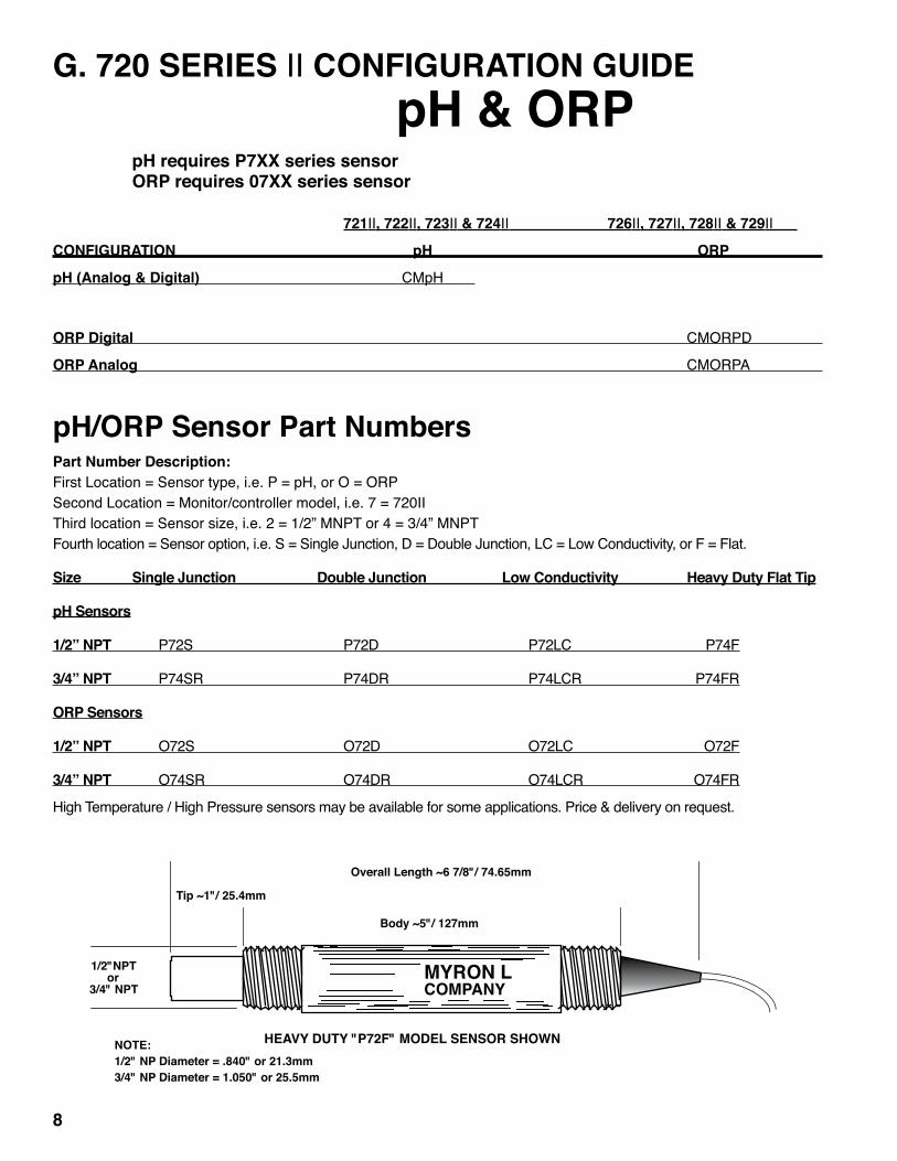
G. 720 SERIES II CONFIGURATION GUIDE pH & ORP pH requires P7XX series sensor ORP requires 07XX series sensor
721II, 722II, 723II & 724II 726II, 727II, 728II & 729II
CONFIGURATION pH ORP
pH (Analog & Digital) CMpH
ORP Digital CMORPD
ORP Analog CMORPA
pH/ORP Sensor Part NumbersPart Number Description:First Location = Sensor type, i.e. P = pH, or O = ORPSecond Location = Monitor/controller model, i.e. 7 = 720IIThird location = Sensor size, i.e. 2 = 1/2” MNPT or 4 = 3/4” MNPTFourth location = Sensor option, i.e. S = Single Junction, D = Double Junction, LC = Low Conductivity, or F = Flat.
Size Single Junction Double Junction Low Conductivity Heavy Duty Flat Tip
pH Sensors
1/2” NPT P72S P72D P72LC P74F
3/4” NPT P74SR P74DR P74LCR P74FR
ORP Sensors
1/2” NPT O72S O72D O72LC O72F
3/4” NPT O74SR O74DR O74LCR O74FR
High Temperature / High Pressure sensors may be available for some applications. Price & delivery on request.
8
NOTE:1/2" NP Diameter = .840" or 21.3mm3/4" NP Diameter = 1.050" or 25.5mm
MYRON L COMPANY
Overall Length ~6 7/8"/ 74.65mm
Tip ~1"/ 25.4mm
Body ~5"/ 127mm
1/2"NPTor
3/4" NPT
HEAVY DUTY "P72F" MODEL SENSOR SHOWN

II. INSTALLATIONA. GENERALThis section provides the recommended procedures for properly installing the 720 Series II pH/ORP Monitor/controller, and sensors. For OEM models see section II.C.
WARNING: THE Myron L® Company RECOMMENDS THAT ALL MOUNTING AND ELECTRICAL INSTALLATIONS BE PERFORMED BY QUALIFIED PERSONNEL ONLY. FAILURE TO DO SO COULD CAUSE DAMAGE TO INSTRUMENT, AND COULD BE HARMFUL OR FATAL TO PERSONNEL.
B. MECHANICAL INSTALLATIONAll Monitor electronics are packaged inside drip/weather-proof housings. The physical dimensions of the housing is suitable for panel, bench or surface mounting.
There are three basic guidelines to consider when selecting a Monitor’smountinglocation:
1. SelectasitethatlimitstheMonitor/controller’sexposure to excessive moisture and corrosive fumes. 2. If at all possible, mount the Monitor/controller at eye level for viewing convenience. 3. If needed, the enclosure may be rotated or mounted upside down so that the cutouts are on the opposite side.
1. SURFACE MOUNTING WITH SMP NOTE: A Surface Mounting Plate (SMP50) may be required when access to the back side of the mounting site is impractical or if the Monitor/controller must be mounted on a solid wall. The SMP50 comes with the proper hardware to mount the Monitor/controller to the SMP, however, the installer must provide
the four (4) additional screws/bolts to mount the SMP to the wall or fixture.Theirsizeistobedeterminedbytheuser.
1. Select your mounting location. Mark four (4) required mounting holes. For hole locations, use the SMP as a template. 2. Drill the corner holes in the SMP according to the size of the screws or bolts selected. 3. Attach and securely fasten the SMP to the Monitor using the 1/4” - 20 X 3/8” screws provided. 4. Mount the SMP to the prepared site using the selected screws or bolts.
2. SURFACE MOUNTING WITHOUT SMPNOTE: Surface mounting will require two (2) 1/4” - 20 screws of a length equal to the thickness of the mounting site plus 3/8”.
1. Select mounting site location. Mark and drill the required mountingholes.Forholedrillinglocations,seefigure II.B.1. 2. Insert the 1/4” - 20 screws into the holes from the side opposite the mounting site. 3. Hold the Monitor/controller in place while starting and tightening the mounting screws.
3. PANEL MOUNTINGA panel mounting fastening kit is provided with all Monitor/controllers. Panel mounting will require the use of the fasteningkit’stwo(2)4-40mountingscrews/nutsortwo(2)#4- 1/2”sheetmetalscrews.SeefigureII.B.1forpanelcutoutdimensions.
1. Select your mounting location. Mark the appropriate panel cutout and complete the necessary panel cut. 2. CarefullyunfastenandseparatetheMonitor/controller’s front panel from its enclosure. 3. Disconnect all panel cable(s)/wires from the Monitor/controller’smaincircuitboard.
9
! CAUTION - READ FOLLOWING CAREFULLY
DOUBLE INSULATED
SURFACE AND PANEL MOUNTING DIAGRAMS
NOT TO SCALEDIMENSIONS IN INCHES
(MILLIMETERS)
HIGHLOW
SET POINT
4.80(122)
3.89(99)
0.63 THK(16)
3.10(79)
0.40(10)
SURFACE MOUNT
1.05(27)
2.84(72)
0.31 DIA, X2(8)
5.00(127)
3.96(101)
0.13 RAD MAX, X4(3)
0.113(3)
2.54(64)
4.17(106)
0.11(3)
PANEL CUTOUT
6.00(152)
0.5(13)
0.88 DIA(22)
1.13 DIA(29)
0.53(14)
4.94(126)
0.60 DIA(15)
3.78(96)
0.50 DIA(13)
Figure II.B.1.
MYRON LCOMPANY
Face Plate Gasket Panel Gasket
Face Plate GasketPanel Gasket
pH
6-32x3/8 ”x4

4. Slide the enclosure through the panel cutout untilitsflangecontactsthepanel. 5. Insertmountingscrewsthroughtheflange mounting holes and tightly secure. 6. Reconnect all panel cable(s)/wires and re- secure the front panel using 6-32 x 3/8” screws provided.Caution: Do not use 6-32 x 1/2” used on “picture frame” front panel models.
C. CIRCUIT BOARD AND DISPLAY MOUNTINGThis section provides the recommended procedures for properly installing the OEM 720 Series II pH/ORP Monitor/controller.
NOTE: Mounting of the OEM monitor/controller circuit board is left up to the OEM. It is recommended that the following be noted and observed.
1. CIRCUIT BOARDTotal height of CB is 1.40” (36mm).The circuit board has four .175” (4.4 mm) holes for mounting. The centersare3.10”(78.7mm)x4.10”(104.1mm)seefigureII.C.1.CB must be mounted on at least .250” (6.35 mm) standoffs to prevent shorting to metal chassis (standoffs user supplied).CB must be mounted in a clean and dry environment. Allow working room for inserting wires, testing and calibration. Indicator lights and switches require 1/4” (6.35mm) holes.
2. METER MOVEMENTRefertofigureII.C.2fordimensions. 1. Cut opening in user panel. 2. Drill four holes at locations as shown. 3. Install meter movement.
3. DIGITAL DISPLAY RefertofigureII.C.3fordimensions. 1. Cut opening in user panel 2. Install LCD with brackets supplied.
10
3.100(78.74)
4.100(104.1)
4.585(116.5)
3.600(91.44)
Figure II.C.1Figure II.C.3
2.390(60.71)
.980(24.89)
Digital Display Cutout Pattern
Figure II.C.2
.125 X4
2.218 Dia.
.940
1.880
.940
.940
(23.88)(23.88)
(23.88)
(3.125)
56.34(47.75)
Analog Meter Hole Pattern

D. SENSOR INSTALLATIONThepH/ORPSensor’smountingorientationmustprovidea continuousandadequatecirculationflowtopreventthetrapping ofairbubbleswithintheSensor’selectrodearea.Failuretodoso will result in conditions that will prevent the Sensor from functioning properly. 1. INSERTION MODE (in-line installation)Use one of the following as a guide. The Heavy Duty pH or ORP sensor may be installed in any direction including inverted (sensor UP). Substitute ORP sensor for pH where applicable.Use approved sealant, i.e. Teflon tape as required. 1. InserttheSensorFittingassemblyintothe“T”fittingas showninoneofthefiguresbelow. 2. Tightly secure. 2. IMMERSION OR DIP SENSOR ASSEMBLYUse approved sealant, i.e. Teflon tape as required. 1. InsertandpulltheSensor’scablethroughtheextension tubeasshowninfigureII.D.2. 2. Tightly attach extension tube to Sensor assembly as showninfigure.II.D.2.
The sensor cable may be extended as necessary.Additional cable may be ordered: Part Number pHCRD-(length) Example: pHCRD-300(90m)NOTE: 1000 ft/300 meter cable lengths have been tested with no adverse affects on the readings. However, unusual conditions may be experienced when extended long distances, i.e. power or ground reversal. These conditions are beyond the control and responsibility of the Myron L® Company. A clean installation is required. If you are experiencing errors, check the Monitor/controller with a 10 ft/3 meter cable before contacting your distributor or the Myron L® Company.
11
NOTE:HEAVYDUTY“F”MODELSENSORSMAYBE INSTALLED IN ANY DIRECTION INCLUDING INVERTED. Figure II.D.2
IMMERSION OR DIP INSTALLATION
"T" FITTING
OUT IN
CABLE
MYRON L COMPANY
Figure II.D.1.d
HEAVY DUTY "F" MODEL INSTALLED INVERTED - BASE OF "T"
METHODS OF
INSTALLATION
Figure II.D.1.a
MYR
ON L C
OMPA
NY
CABLE
"T" FITTING
INSTALLED 45° - BASE OF "T"
Figure II.D.1.c
HEAVY DUTY "F" MODEL INSTALLED HORIZONTALLY - BASE OF "T"
CABLE"T" FITTING
MYRON L COMPANYMYRON L COMPANY
"T" FITTING
OUT IN
INSTALLED VERTICALLY - BASE OF "T"
Figure II.D.1.b
CABLE
CABLE
MYRON L COMPANYMYRON L COMPANY
COUPLING
MYRON L COMPANY
MYRO
N L
CO
MPA
NY
MYRO
N L
CO
MPA
NY
MYRO
N L
CO
MPA
NY

E. ELECTRICAL INSTALLATIONThe electrical installation procedures provided in this manual are commontoallpH&ORPMonitor/controllers.SeefigureII.B.1for theholedimensionsoftheenclosure’scableaccessholes. Unlessotherwiseinstructed,refertofigureII.E.1.forthe720 Series IIMonitor’sterminalblockconnectorwiringdesignations.
NOTE:Afterremovinganenclosure’saccessholeplug,itis suggestedthattheusermountawatertightrestraintfixturepriorto installing a cable.
A device to disconnect the Model 720II from the power supply is required. It is recommended that this switch or circuit breaker be labeled as the disconnection device for the Model 720II.
1. MAIN INPUT POWER INSTALLATIONWARNING: All Monitor/controllers are factory set for 115 VAC. Before starting, ensure the input power “115/230” selection is correct for your requirements. Failure to do so is beyond the responsibility of the Myron L® Company. See section II.E.2 below and figure II.E.1.NOTE: Some models may have either a 24 VAC or a 24 VDC input power requirement - check labels carefully.
1. Verifythatthemainpowersourceisturned“OFF” or disconnected. 2. Using a standard slot screwdriver remove the screws on the front panel. 3. Carefully wiggle the front panel to loosen the gasket and pull gently toward you. Do not pull more than about 8 inches/20CM or you could damage the wiring harness. 4. Turn the front panel around so that the back side is facing you and set aside for now. 5. Carefully remove front panel, leaving the harness connected. For OEM models skip to step #4. 6. Using the enclosure cutouts, install the proper wire and watertight cable restraint (not provided) to comply with local electrical codes. Skip for OEM. 7. NeatlyconnectwirestotheMonitor/controller’s connectors,asshowninfigureII.E.1.
*CAUTION: The input power connectors require only a small screwdriver or a pen to push on the release levers. The release levers may be broken or damaged if not pushed straight toward the circuit board. DO NOT push the release levers sideways.
2. 115/230 VAC CONVERSION 1. Before turning power on to the Monitor/controller ensure the proper input voltage has been selected. Failure to do so will blow the fuse. It could, under some conditions, cause injury and damage the instrument voiding the warranty. 2. Locate switch located next to the fuse holder. 3. Using a screwdriver, turn switch to required voltage.
3. CONNECTING THE SENSOR CABLE For OEM models skip #1.A 10 ft/3 meter sensor cable length is standard. 25 ft/7.5 meter and 100 ft/30 meter cable lengths are available as options. The sensor cable may be extended up to 1000 feet/300 meters by ordering cable only. It is recommended proper water tight and shielding methods (i.e. junction box) be used when extending the cable. Cable only: Part Number pHCRD-(length) Example: pHCRD-300 (90m)
NOTE: 1000 ft/300 meter cable lengths have been tested with no adverse affects on the readings. However, unusual conditions may be experienced when extended long distances, i.e. power or ground reversal. These conditions are beyond the control and responsibility of the Myron L® Company. A clean installation is required. If you are experiencing errors, check the Monitor/controller with a 10 ft/3 meter cable before contacting your distributor or the Myron L® Company.
1. Place the sensor cable and user supplied watertight cablerestraintintotheenclosure’sappropriateaccess hole. 2. Install the sensor cable wire to comply with local electrical codes. Follow the color code as marked. See figureII.E.1.
CAUTION: The circuit board connectors require only a small screwdriver or a pen to push on the release levers. The release levers may be broken or damaged if not pushed straight toward the circuit board. DO NOT push the release levers sideways.
a. MODIFICATION FOR US PHARMACEUTICAL 25 (No Temperature Compensation)ThissimplemodificationwillallowyourMonitor/controllertomeet the USP 25 requirements by disabling the normal temperature compensation circuit thus giving “uncompensated” readings as required.
12
! WARNING !
! CAUTION - READ FOLLOWING CAREFULLYELECTRICAL CONNECT DIAGRAM
CHASSIS GROUND forOEM INSTALLATIONS ONLY
SENSOR
L N
0-10VDCOUTPUT
NEUGRNREDWHTBLK
(+) (-)
ALARMCONTROLRELAY
COM NO NC
MAIN INPUTPOWER
GND-GRNNEU-WHT / -DCLINE-BLK/ +DC
FUSE115/ 230SWITCH
Figure II.E.1
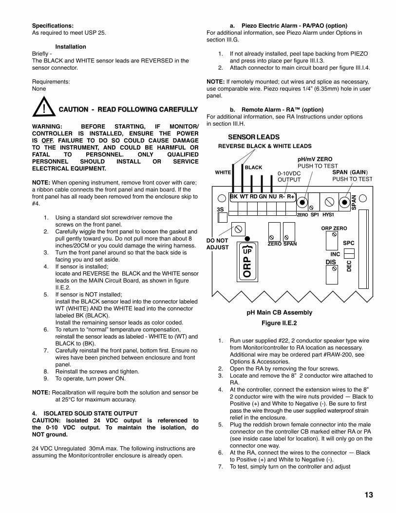
Specifications:As required to meet USP 25.
InstallationBriefly-TheBLACKandWHITEsensorleadsareREVERSEDinthesensor connector.
Requirements:None
WARNING: BEFORE STARTING, IF MONITOR/ CONTROLLER IS INSTALLED, ENSURE THE POWER IS OFF. FAILURE TO DO SO COULD CAUSE DAMAGE TO THE INSTRUMENT, AND COULD BE HARMFUL OR FATAL TO PERSONNEL. ONLY QUALIFIED PERSONNEL SHOULD INSTALL OR SERVICE ELECTRICAL EQUIPMENT.
NOTE: When opening instrument, remove front cover with care; a ribbon cable connects the front panel and main board. If the front panel has all ready been removed from the enclosure skip to #4.
1. Using a standard slot screwdriver remove the screws on the front panel. 2. Carefully wiggle the front panel to loosen the gasket and pull gently toward you. Do not pull more than about 8 inches/20CM or you could damage the wiring harness. 3. Turn the front panel around so that the back side is facing you and set aside. 4. If sensor is installed; locateandREVERSEtheBLACKandtheWHITEsensor leadsontheMAINCircuitBoard,asshowninfigure II.E.2. 5. If sensor is NOT installed; install the BLACK sensor lead into the connector labeled WT (WHITE) AND the WHITE lead into the connector labeled BK (BLACK). Install the remaining sensor leads as color coded. 6. To return to “normal” temperature compensation, reinstall the sensor leads as labeled - WHITE to (WT) and BLACK to (BK). 7. Carefullyreinstallthefrontpanel,bottomfirst.Ensureno wires have been pinched between enclosure and front panel. 8. Reinstall the screws and tighten. 9. To operate, turn power ON.
NOTE: Recalibration will require both the solution and sensor be at 25°C for maximum accuracy.
4. ISOLATED SOLID STATE OUTPUTCAUTION: Isolated 24 VDC output is referenced to the 0-10 VDC output. To maintain the isolation, do NOT ground.
24VDCUnregulated30mAmax.Thefollowinginstructionsareassuming the Monitor/controller enclosure is already open.
a. Piezo Electric Alarm - PA/PAO (option)For additional information, see Piezo Alarm under Options in section III.G.
1. If not already installed, peel tape backing from PIEZO andpressintoplaceperfigureIII.I.3. 2. AttachconnectortomaincircuitboardperfigureIII.I.4.
NOTE: If remotely mounted; cut wires and splice as necessary, use comparable wire. Piezo requires 1/4” (6.35mm) hole in user panel.
b. Remote Alarm - RA™ (option) For additional information, see RA Instructions under options in section III.H.
1. Run user supplied #22, 2 conductor speaker type wire from Monitor/controller to RA location as necessary. Additional wire may be ordered part #RAW-200, see Options & Accessories. 2. Open the RA by removing the four screws. 3. Locate and remove the 8” 2 conductor wire attached to RA. 4. At the controller, connect the extension wires to the 8” 2 conductor wire with the wire nuts provided — Black to Positive(+)andWhitetoNegative(-).Besuretofirst pass the wire through the user supplied waterproof strain relief in the enclosure. 5. Plug the reddish brown female connector into the male connector on the controller CB marked either RA or PA (see inside case label for location). It will only go on the connector one way. 6. At the RA, connect the wires to the connector — Black to Positive (+) and White to Negative (-). 7. To test, simply turn on the controller and adjust
13
! CAUTION - READ FOLLOWING CAREFULLY
HYS1SP1
SPAN
ZERO
DIS
ORP ZERO
SPANZERO
Figure II.E.2
3S
pH/mV ZEROPUSH TO TEST
INC
DEC
SPC
pH Main CB Assembly
0-10VDCOUTPUT
SENSOR LEADSREVERSE BLACK & WHITE LEADS
SPAN (GAIN)PUSH TO TEST
DO NOT ADJUST
WHITEBLACK
UP
OR
P
BK WT RD GN NU R- R+
SPAN
DEC

controller set point until the alarm/piezo sounds off. If controller is not yet connected to a functioning sensor, it may be necessary to press and hold the ZERO test switch. The black button on the front of the RA will mute the piezo alarm for approximately three minutes or until you improve the water quality (readjust controller set point). The piezo alarm will continue to sound off every three minutes until the user has improved the alarm condition insidethecontroller.Ifthreeminutesmutingisfinefor your application, skip to step 9. 8. If three minutes is too long or too short, adjust time delay control inside RA until desired mute time is achieved (adjustable from approximately 6 seconds to 10 minutes). 9. Replace the bottom of the RA, and secure RA to the surface you have selected for its installation. NOTE: If the RA does not sound off; 1. Check the polarity of the extension wire connections. 2. Be sure the controller is actually switching (relay will click). c. Connect to your own alarmUse the following as guidelines. Connector is a standard 2 wire Methode* style connector. Connector with 8” wires, part #RAH, is available from the Myron L® Company. Ensureyourrequirementsdonotexceedthe24VDC Unregulated 30mA maximum. Ensure the polarity is correct (RED is positive), see figureV.A.1. Attach wires to RA. Attachconnectortocontrollerconnector(RA)perfigure V.A.1.*Methode is registered trademark of Methode Electronics, Inc.
5. ALARM/CONTROL RELAY CONNECTIONSMyron L® Company Monitor/controllers are equipped with a “Dry Contact” relay which is designed to energize/de-energize when thesetpointiscrossed.(SeesectionIV.C.3forsetpoint adjustment procedure) The relay energizes on increasing or decreasingreadingsassetbytheuser,seesectionIV.C.1.When energized (above set point), the Common (CM) will disconnect from the Normally Closed (NC) contact and connect to the Normally Open (NO) contact. Devices may be operated using either the Normally Open contact or Normally Closed contact; or both relay contacts may be used to control two devices of the
same voltage. NOTE:Aflowswitchmaybeinstalled(electricallyconnected)utilizing one of two convenient methods; the 3S connection, see figureII.E.2,(removejumperandconnectflowswitchacrossterminals - 8” harness (RAH) available from the Myron L Company),orinlinewitheitherrelayconnection,seefigureII.E.3 or II.E.4.
WARNING: CONNECTING BOTH POWER SOURCE LEADS TO THE RELAY TERMINAL BLOCK CONNECTORS WILL DAMAGE THE CIRCUIT BOARD AND MAY CAUSE PERSONAL INJURY.
1. Place the user supplied Alarm relay interface cable and watertightcablerestraintintotheenclosure’s appropriate access hole. Skip for OEM. 2. Neatly connect the relay interface cable wires to the Monitor/controller’sterminalblockconnectors,see figuresII.E.1,II.E.4orII.E.5.
CAUTION: The connectors require only a small screwdriver or a pen to push on the release levers. The release levers may be broken or damaged if not pushed straight toward the circuit board. DO NOT push the release levers sideways.
TheeasiestmethodofconnectingtherelayisshowninfiguresII.E.1, and II.E.3. These show how the dry contact relay can use incoming power to activate a controlled device (alarm, solenoid valve, etc.) of 10 amps or less.
For24VACapplications,theMyron L® Companyoffersa115VAC to24VACtransformer,Model#VR,seefigureII.E.4.Other voltages must be user-supplied.
6. CONNECTING DISPLAY HARNESS TO DISPLAYIf the installation required the removal of the display harness from the display (OEM installation requires connection), the following procedure will ensure it is reinstalled without damaging the display.
WARNING: THE DISPLAY WILL BE IRREPARABLY DAMAGED IF THE HARNESS IS INSTALLED UPSIDE- DOWN OR MISALIGNED. THE HARNESS MUST BE INSTALLED AS SHOWN IN FIGURE II.E.5.
14
Figure II.E.3
DEVICE TO BE
CONTROLLED
POWER SOURCE
COM
NO
CM
NO
NCRELAY
RELAYTERMINAL BLOCK
MONITOR/CONTROLLERCIRCUIT BOARD
OPT. FLOW
SWITCH
X
Figure II.E.4
DEVICE TO BE
CONTROLLED
COM
NO
115VACPOWER SOURCE
CM
NO
NCRELAY
VR
RELAYTERMINAL BLOCK
115 to 24VACTRANSFORMER
MONITOR/CONTROLLERCIRCUIT BOARD
OPT. FLOW
SWITCH
X

1. Grasp connector and align wires DOWN on display or withthesmalledgeofthedisplayasshowninfigure II.E.5. 2. Press connector onto display pins. Ensure pins are aligned or they may become bent. Wiggle connector slightly “end to end” if necessary.
F. 0-10 VDC RECORDER OUTPUTThe0-10VDCoutputisdesignedtogivetheuserthecapabilityof sending a signal to a remote meter, recorder, PLC or SCADA system.
1. CONNECTION 1. Place the user supplied interface cable and watertight cablerestraintintotheenclosure’sappropriateaccess hole. Skip for OEM. 2. ConnecttheRecorder’splus(+)andminus(-)terminal wirestotheRecorderoutputconnectors.(Seefigure II.F.1) 3. RefertoSectionV.C.1.bfortheprocedurestocalibrate the0-10VDCvoltageoutput.
2. VOLTAGE DIVIDERA voltage divider gives the user the ability to scale or tailor the output to a particular need or requirement due to the input of anotherdevice,i.e.theoutputoftheMainCBis0-10Vwhiletheinputrequirementofaparticularrecordingdeviceis0-5V.
a. INSTALLATIONBriefly—Tworesistorsareinstalledacrossthe0-10Voutput.The output is recalibrated to required voltage.
RequirementsSelect two (2) resistors as listed; For0-5VOutputboth“A&B”are2KResistors. For0-1VOutput“A”isa9Kresistorand“B”isa1Kresistor.
WARNING: BEFORE STARTING, IF MONITOR/ CONTROLLER IS INSTALLED, ENSURE THE POWER IS OFF. FAILURE TO DO SO COULD CAUSE DAMAGE TO THE INSTRUMENT, AND COULD BE HARMFUL OR FATAL TO PERSONNEL. ONLY QUALIFIED PERSONNEL SHOULD INSTALL ELECTRICAL EQUIPMENT.
PhysicalIf the front panel has all ready been removed from the enclosure skip to #3.
1. Using a standard slot screwdriver remove the screws on the front panel. 2. Carefully wiggle the front panel to loosen the gasket and pull gently toward you. Do not pull more than about 8 inches/20CM or you could damage the wiring harness. 3. Turn the front panel around so that the back side is facing you and set aside for now. 4. Soldertwoselectedresistorstogetherasshowninfigure II.F.1. 5. Attachleadstorecordingdeviceasshowninfigure II.F.1. 6. Attachresistorsto0-10VOutputasshowninfigure II.F.2. Ensure resistors and leads DO NOT short to each other or to any part of the CB assembly. 7. Recalibration is required, see Calibration Procedures, sectionV.C.
Reassembly 1. Carefullyreinstallthefrontpanel,bottomfirst,ensureno wires have been pinched. 2. Reinstall the screws and tighten. 3. To operate, turn power ON.
15
0-10V Output
+
-
A
B
+
-Recording Device
Figure II.F.1
3S
SENSOR LEADS
0-10VDCOUTPUT
- +
NEWOUTPUTASSELECTED
Main CB AssemblyFigure II.F.2
SPANZERO
ZERO
DO NOT ADJUST
BK WT RD GN NU R- R+
PANEL MOUNTED DISPLAYREAR VIEW
DISPLAY CONNECTION
DISPLAYHARNESS
DISPLAY
Figure II.E.5
! CAUTION - READ FOLLOWING CAREFULLY

G. RE-CONFIGURE YOUR MONITOR/CONTROLLER (Configuration Module Installation)
1. DESCRIPTIONThe 720 Series II Monitor/controllers have been designed for easyfieldre-configurability.TheConfigurationModuleconsistsof a 16 pin Header that plugs into a 16 pin socket.
NOTE: Changing from pH to ORP or visa versa, requires a different sensor.
pH Module — pH14ORP Module — ORP2A ANALOG Module† ORP Module — ORP2D DIGITAL Module†
NOTE: SomeOEMmodelsmaynotbere-configuredbeingoriginallymanufacturedwithfixedresistors.Ifyourapplicationrequiresre-configuringanOEMmodel,firstcontactthesystem manufacture for help. The Myron L®Companymayre-configureor exchange your instrument at a cost.
2. INSTALLATIONBriefly-ThenewConfigurationModulesimplyreplacestheConfiguration Modulepresentlyinstalled,seefigureII.G.1.Type label will be required if changing from pH to ORP or visa versa. ZERO and SPAN recalibration is performed.
IMPORTANT NOTES: 1. CHANGING FROM pH TO ORP OR VISA VERSA
WILL REQUIRE A SCALE CHANGE ON ANALOG MODELS. SEE SECTION II.G.4 FOR INSTRUCTIONS.
† 2. ANALOG and DIGITAL ORP MODELS REQUIRE DIFFERENT CONFIGURATION MODULES. SEE FIGURES II.G.8 AND II.G.9.
WARNING: BEFORE STARTING, IF MONITOR/ CONTROLLER IS INSTALLED, ENSURE THE POWER IS OFF. FAILURE TO DO SO COULD CAUSE DAMAGE TO THE INSTRUMENT, AND COULD BE HARMFUL OR FATAL TO PERSONNEL. ONLY QUALIFIED PERSONNEL SHOULD INSTALL OR SERVICE ELECTRICAL EQUIPMENT.
PhysicalNOTE: When opening instrument, remove front cover with care; a ribbon cable connects the front panel and main board. If the front panel has all ready been removed from the enclosure skip to #4.
1. Using a standard slot screwdriver remove the screws on the front panel. 2. Carefully wiggle the front panel to loosen the gasket and pull gently toward you. Do not pull more than about 8 inches/20CM or you could damage the wiring harness. 3. Turn the front panel around so that the back side is facing you and set aside. 4. LocateandremoveexistingConfigurationModulefrom MAINCircuitBoard,asshowninfigureII.G.1.Itisnot
easy to remove, it was designed to stay in place under adverse conditions. 5. Withthepointerup,carefullyalignthenewconfiguration Module to the socket on the MAIN Circuit Board as shown infigureII.G.1. 6. Pressfirmlyintoplace. 7. Analog models will require the meter scale to be changed. See Changing Analog Meter Scale, section II.G.3. 8. Recalibrate,seeCALIBRATIONPROCEDURES,V.C.
16
! CAUTION - READ FOLLOWING CAREFULLY
Figure II.G.1
REMOVE TO INSTALL
FUSE*115/ 230
TRANSFORMER
Main CB Assembly
721 726722 727723 728724 729
MYRON L COMPANY
CONFIGURATIONMODULE
UP
3S
INC
DEC
SPCSPANZERO
HYS1SP1
SPAN
ZERO
POINTER
DO NOT ADJUST
0-10VDCOUTPUT
7 pH/ZERO mVPUSH TO TEST
DIS
ORP ZERO
SPAN (GAIN )PUSH TO TEST
BK WT RD GN NU R- R+
PWR C GD NC NO CM
PAR
AGN
D
CHS
REM
OVE
TO
INST
ALL
SE
CO
ND
REL
AY
pH
SPAN
DEC

3. CHANGING ANALOG METER SCALE (DIAL)Afterchangingconfigurations(pHtoORPorvisaversa)onan analog model 720II it will be necessary to change the meter scale (dial). The following steps will guide you through the change. Please read caution carefully.
Exercise extreme caution while working on meter. Meter movement, and/or pointer (needle) may be damaged beyond repair. It is recommended only qualified personnel change scales. DO NOT allow dust to enter the case while it is open.Failure to follow these instructions may cause irreparable damage, and will VOID the warranty.
Briefly-The meter is removed from front panel (except OEM models).The cover is removed.The hex screws retaining the scale are removed, and scale is slid out the top. New scale is slid in place, and screws reinstalled. Cover aligned, installed and zero set.
PhysicalFor OEM models skip to #4.
1. Using a wrench, nut driver or pliers remove the two (2) large nuts retaining the circuit board wiring harness connectors. Red wire is PLUS (+), BrownwireisMINUS(-).SeefigureII.G.2. 2. Using a standard slot screwdriver remove the four (4) screws, and the backing plate holding the meter to the frontpanelasshowninfigureII.G.2. 3. Remove meter. Do not lose the gasket between the meter and the front panel, it must be reinstalled upon reassembly.SeefigureII.G.3.Aligngaskettofront panel so as the gasket does not show when meter is assembled to front panel.
4. Using a wide blade standard slot screwdriver, starting at a bottom corner, CAREFULLY pry the clear plastic cover loosefromthemovementcase.SeefigureII.G.4.
5. Using a 1/8” (3.2mm) hex driver, remove the two (2) small screwsholdingthescale(dial).SeefigureII.G.5. 6. To remove the scale, lightly press on bottom of scale, the top will lift up. Be extremely careful not to bend the pointer (needle) or to move the Zero Adjust (ZA). SeefigureII.G.5.
7. Grasp top and slide scale slowly out from top. Be extremely careful not to bend the pointer (needle) or to movetheZeroAdjust(ZA).SeefigureII.G.5.
17
CLEAR COVERPry Here Carefully
CASEFigure II.G.4
Figure II.G.5
Grasp Scale Hereand Slide Out TOP
SCALE (dial)Pointer (needle)
Inverted "Y"
1/8" (3.18mm) Hex Screws (2)
METER CASE
Press Lightly Here
0
! CAUTION - READ FOLLOWING CAREFULLY
GASKET
Figure II.G.3
Figure II.G.2 Harness to Main CB Connector
+Backing Plate
METER
Mounting Screws (4)
BROWN WIRERED WIRE

8. Reverse the above procedure using the new scale.
NOTE: While replacing the clear plastic cover, ensure the ZA screw pin on the cover aligns with the inverted “Y” shaped slotonthemetermovement.SeefigureII.G.5.IF, the inverted “Y” shaped slot is inadvertently moved - BEFORE installing cover: a. Recenter the inverted “Y” to the meter case as showninfigureII.G.5. b. Center the Zero Adjust (ZA) PIN on the clear plasticcoverasshowninfigureII.G.6. 9. Using a standard slot screwdriver, ensure the ZA is operating - pointer swings left and right when turning the ZAwithastandardslotscrewdriver.SeefigureII.G.7. 10. SetMeterZEROasshowninfigureII.G.7. 11. Reinstall meter to front panel, reversing steps 1-3 (except OEM models).
REASSEMBLY 1. Carefullyreinstallthefrontpanel,bottomfirst,ensureno wires have been pinched. 2. Reinstall the screws and tighten. 3. To operate, turn power ON.
18
Figure II.G.6
CLEAR PLASTIC COVER(Inside View)
CENTER Zero Adjust (ZA) PIN
Figure II.G.7
Zero Adjust (ZA)CLEAR PLASTIC COVER
(case not shown for clarity)
0Align Pointer with FIRST Line
Figure II.G.8
UP
PIN #10ANALOGREMOVED
Bottom View
ORP CONFIGURATION
MODULE
UP
Top View
O
RPD
OO
RPA
O
“ANALOG”
Figure II.G.9
UPPIN #12DIGITALREMOVED
Bottom ViewORP "DIGITAL"
CONFIGURATION MODULE
UP
Top View
OR
PA O
OR
PD O

III. OPTIONS & ACCESSORIESA. SC/SCO MODULE (SECOND ALARM/CONTROL OPTION) (Digital & OEM Models ONLY)-SC Second Alarm Control Module ordered with Monitor/controller.SCO Second Alarm Control Module Kit ordered separately.
1. DESCRIPTION:An essential component for applications requiring a DUAL setpoint. The Second Alarm/control module allows the user additionalflexibilitybybeingabletosoundTWOAlarms,and Control TWO functions with the second 10 amp relay. The set points are non-overlapping. The #2 alarm/control (HIGH set point) rides on top of the #1 alarm/control (LOW set point). SCO kit comes with all items necessary to install and operate: SC Module, front panel harness with LED, switch, bezel, cap and two O-rings (006 & 008); and replacement lower front panel label (L2ALARM).
Specifications:Control Function: Setpoint control continuously adjustable 0-100% of spanHysteresis: Adjustable from 0.3-3% of full scaleIndicators: Above (red) and below (green) setpoint LEDs (reversible)Relay Contact Rating: SPDT10amp~250VAC,30VDC.Relayoperates increasing or decreasing reading (selectable)Solid State Output: Powered—24VDC30mAMaximum
2. INSTALLATION:Briefly-The Second Alarm/control module plugs into the main Monitor/controller circuit board.The LED/switch harness is installed into the front panel.Set point and hysteresis are set per “your“ requirements. If this option is installed, skip to III.A.2.a.
WARNING: BEFORE STARTING, IF MONITOR/ CONTROLLER IS INSTALLED, ENSURE THE POWER IS OFF. FAILURE TO DO SO COULD CAUSE DAMAGE TO THE INSTRUMENT, AND COULD BE HARMFUL OR FATAL TO PERSONNEL. ONLY QUALIFIED PERSONNEL SHOULD INSTALL OR SERVICE ELECTRICAL EQUIPMENT.
PhysicalIf the front panel has all ready been removed from the enclosure skip to #3. MAIN Circuit Board
1. Using a standard slot screwdriver remove the screws on the front panel. 2. Carefully wiggle the front panel to loosen the gasket and pull gently toward you. Do not pull more than about 8 inches/20CM or you could damage the wiring harness. 3. Turn the front panel around so that the back side is facing you and set aside for now. 4. Remove BLACK JUMPER from MAIN Circuit Board connector located next to the transformer as shown in figureIII.A.2.NOTE: Do not lose BLACK JUMPER. It must be reinstalled if second relay is removed for any reason and the #1 relay is expected to operate. 5. Carefully press the SCO Second Alarm/Control Module intoMAINCircuitBoardasshowninfigureIII.A.4. When fully seated the SCO Module will snap into place. 6. Connect the Solid State output to PA or user supplied 24VDC/30mAalarm/valveor??,and/orcontrolwires torelay#2,asrequired,seefigureIII.A.4*. a. Place the control cable and user supplied watertightcablerestraintintotheenclosure’s appropriate access hole. b. Neatly connect the control wires to the Monitor/controller’sappropriateconnectors.See figureIII.A.4.*CAUTION: The relay connectors require only a small screwdriver or a pen to push on the release levers. The release levers may be broken or damaged if not pushed straight. DO NOT push the release levers sideways.
19
! CAUTION - READ FOLLOWING CAREFULLY
OPTIONAL SECOND ALARM/CONTROL MODULE
SPCINC
PA
LED/SWITCH HARNESS
RUBBER TAPE (DO NOT REMOVE - MUST BE IN PLACE TO PREVENT SHORT)
SET POINT #2CONVERSION
SET POINT #2HYSTERESIS SET POINT #2 (high)
ADJUST
COMRELAY #2NO
NC
SOLID STATE OUTPUT (24VDC 30mA) PA™ PIEZO ELECTRIC ALARM ORRA™ REMOTE ALARM ORCUSTOMER CONNECTION
Figure III.A.1
CM
NO
NC

Front PanelWARNING: there are two (2) O-rings installed on the switches, one (1) on the shank and the other is under the push button. Both of these O-rings must be reinstalled to maintain IP65/NEMA 4X ratings.SeefigureIII.A.3.
1-4 assumes this is a conversion from a single alarm/control. Skip to #5 if new installation or assembly.
1. Carefully remove the RED LED from the front panel by pulling lightly on the wires. It may be necessary to use a smallflatscrewdrivertoslightlyspreadtheretaining ring. 2. Remove the set point switch from the front panel by rotating the round bezel nut CCW on the front panel, see figureIII.A.4. 3. Remove the LOWER front label. 4. Clean off remaining adhesive, if possible with alcohol. 5. Install DUAL alarm LOWER label, P# L2ALARM. 6. Install the SCO Second Alarm/Control RED LED in the UPPERpositionasshowninfiguresIII.A.5&III.A.6.
7. Install the SCO Second Alarm/Control Set Point Switch in the UPPER center position. 8. Re-install #1 (original) Set Point Switch in the LOWER center position. 9. Re-install the #1 (original) RED LED in the LOWER position. 10. The GREEN LED stays in the same location.
a. Set Point Conversion (SPC) / Reversing Set PointThe alarm/control circuit(s) on all 720 Series II pH and ORP Monitor/controllersareconfiguredtotriggerthealarmrelayasthe reading increases.
Iftheuser’sapplicationrequiresit,thealarm/controlcircuitmay beeasilyreconfiguredtotriggerthealarm/controlrelayasthepH (orORP)readingdecreases.RefertofigureIII.A.4forthe locations of the SPC jumpers referred to in this section.
20
SWITCH
FRONT PANEL
BEZEL PUSH BUTTON
O-RING O-RING
Switch / O-ring AssemblyFigure III.A.3
Figure III.A.2
SET POINT #1CONVERSION
FUSE*115/ 230
TRANSFORMER
RELAY #1COM
POWERAC LINE/ +DC
AC NEUTRAL/ -DCGROUND
NC NO
SOLID STATE (24VDC 30mA) OUTPUTPA™ PIEZO ELECTRIC ALARM ORRA™ REMOTE ALARM ORCUSTOMER CONNECTION
PA
REMOVE JUMPER TO INSTALL SC/SCO SECOND ALARM/CONTROL MODULE
721 726722 727723 728724 729
MYRON L COMPANY
UP
3S
INCSPC
CONFIGURATIONMODULE
SPANZERO
HYS1SP1ZERO
DO NOT ADJUST
pH
SET POINT #1 (high) ADJUST
SET POINT #1HYSTERESISRIGHT INCLEFT DEC
7 pH/ZERO mVPUSH TO TEST
SPAN (GAIN )PUSH TO TEST
DIS
ORP ZERO
PWR C GD NC NO CM
SPA
ND
EC
GN
D
CH
S
RA
PA
REM
OVE
TOSE
COND
REL
AYIN
STAL
L
pH
BK WT RD GN NU R- R+

The following instructions describe the steps for converting the Monitor/controller.RefertofigureIII.A.4forthelocationoftheSPC(s) on your Monitor/controller. If unnecessary, skip to Set Point Adjustment.
1. Ensure power is OFF. 2. LocatetheSPCjumpersforthealarmtobeconfigured, seefigureIII.A.4. 3. Make a note of the current orientation of the SPC jumpers. 4. Remove both jumpers. This is easily done by hand. Take care not to crush the jumpers if using pliers. 5. Rotate the jumpers 1/4 turn (90°) and reinstall them on their posts. 6. Continue with Set Point adjustment.
b. Set Point AdjustmentSet point #1 (LOW) must be adjusted BEFORE adjusting set point #2 (HIGH). 1. Turn power ON. 2. While depressing the lower “SET POINT” switch, turn the SetPoint#1controladjustment,figureIII.A.4untilthe desired set point value is indicated on the display. 3. Repeat for Set Point #2 by depressing the upper “SET POINT” switch and adjusting the SP2 on the SC/SCO ModuleasshowninfigureIII.A.4. 4. Turn power OFF. 5. Continue or reinstall the front panel and tightly secure retaining screws, see REASSEMBLY, page 22.
21Figure III.A.4
SOLID STATE (24VDC 30mA) OutputPA™ PIEZO ELECTRIC ALARM ORRA™ REMOTE ALARM ORCUSTOMER CONNECTION
REMOVE TO INSTALL
SET POINT #1CONVERSION
FUSE*115/ 230
SET POINT #2 (high)ADJUST
SC/SCOOPTIONALSECONDALARM/CONTROLMODULE
SET POINT #2CONVERSION
#2 RELAYLIGHTS &SWITCHCONNECTOR
TRANSFORMER
721 726722 727723 728724 729
MYRON L COMPANY
RUBBER TAPE (DO NOT REMOVE)
RELAY #1COMGROUND
NC NO
SPCINC
PA
COMRELAY #2NO
NC
DIS
ORP ZERO
SOLID STATE (24VDC 30mA) OUTPUTPA™ PIEZO ELECTRIC ALARM ORRA™ REMOTE ALARM ORCUSTOMER CONNECTION
SET POINT #2 HYSTERESISRIGHT INCREASING LEFT DECEASING
3S
INCSPCSPANZERO
HYS1SP1ZERO
DO NOT ADJUST
0-10VDCOUTPUT
SET POINT #1 (low) ADJUST
SET POINT #1HYSTERESISRIGHT INCLEFT DEC
7 pH/ZERO mVPUSH TO TEST
SPAN (GAIN)PUSH TO TEST
UP
pH CONFIGURATIONMODULE
POWERAC LINE/ +DC
AC NEUTRAL/ -DC
BK WT RD GN NU R- R+
PWR C GD NC NO CM CH
S
GN
DPA
RACM
NO
NC
pH
SPA
ND
ECRE
MOV
E TO
SECO
ND R
ELAY
INST
ALL

c. Hysteresis (Dead Band) Adjustment*The hysteresis or dead band is approximately ±3% of the set point at full scale as it leaves the factory. Under normal (most) conditions it will not be necessary to adjust. However, if you desire to make an adjustment please keep the following in mind.The adjustment is very simple and is based on set point location. If the set point* is in the upper 75-100% of the scale, the hysteresis control pot should be turned fully to the right. If the set point is in the lower portion of the scale, i.e. 5-25% of scale, the control pot may be turned fully to the left. If you are operating in the center, 25-75% of scale, the control pot may be adjusted in the center. Or the hysteresis or dead band may be adjusted to tighten the control of a particular process.
CAUTION: Adjusting the hysteresis too narrow may cause the alarmtofluctuate(on-off)duetoflow,chemicalmixingorbubbles causing the relay to chatter. This condition is to be avoided, it could damage your valves, pumps, etc. and will eventually damage the relay.
* Applies to both set points.
The following is assuming the front panel is already removed and the set points have been set, if not see “Set Point Adjustment”.
1. Turn power ON. 2. Locate the Hysteresis Control (HYS1) located next to the Set Point #1 (SP1) adjustment - it is a single turn pot.SeefigureIII.A.4. 3. Adjust as described in “Hysteresis (Dead Band) Adjustment” or as desired. 4. Press set point test switch on the front panel to verify Hysteresis is set as desired. 5. RepeatforSCOModule.SeefigureIII.A.4. 6. Press set point test switch on the front panel to verify Hysteresis is set as desired. 7. Turn power OFF.
d. Second Relay Connection 1. Place the user supplied relay interface cable and watertightcablerestraintintotheenclosure’s appropriate access hole. 2. Neatly connect wires to the relay connector as shown in figureIII.A.4.
e. Solid State Output Options 24VDCUnregulated30mAmax. Same as 4. above, SOLID STATE OUTPUT. 1. Piezo Electric Alarm - PA (option) Plug PA connector to CB as shown (See Figure III.A.4). 2. Remote Alarm - RA™ (option) Plug RA connector to CB as shown (See Figure III.A.4). 3. Connect to your own alarm Ensureyourrequirementsdonotexceedthe24VDC Unregulated 30mA maximum. Ensure the polarity is correct. Attach your wires. Attach harness connector to controller connector (RA) perfigureIII.A.4. If necessary, you may order connector with 8” Harness
part #RAH, from the Myron L® Company. REASSEMBLY: 1. Carefullyreinstallthefrontpanel,bottomfirst.Ensureno wires have been pinched between enclosure and front panel. 2. Reinstall the screws and tighten. 3. To operate, turn power ON.
22
Figure III.A.5
FRONT PANELRear View
Primary/Main CBRed LED
Primary/Main CBSet Point Switch
SC/SCORed LED
LOW
SC/SCOSet Point Switch
Green LED
Figure III.A.6
HIGH
LOWSET POINT
FRONT PANEL Primary or Main CB Alarm/control Location
SC/SCO Location
pH
720II MYRON LCOMPANY

B. 4A/4AO MODULE (4-20mA OPTION)Available only on the digital models 728II, 729II, 723II and 724II, or analog and digital OEM.
-4A 4-20mA Self/Remote-powered Isolated output module ordered with Monitor/controller.4AO 4-20mA Self/Remote-powered Isolated output module ordered separately (includes harness).
1. DESCRIPTIONThe 4-20mA option gives the Series II Monitor/controller the ability to send a signal very long distances with minimal interferences and signal degradation. The output is an Isolated 4- 20mA signal that corresponds to the full scale range of the Monitor/controller into which it is installed. This output is easily configuredtobeeitherself-poweredorremote-poweredas required for your particular application.
NOTE:Themaximumimpedanceoftheuser’scurrentsensorshould not exceed 400 ohms.
Since the output is an isolated current loop, it is the ideal choice for applications requiring; a control signal to be run very long distances, systems requiring a 4-20mA input or in instances where isolation is necessary.
As the output is isolated, and a current, it is useful for long distance interface, especially where wiring resistances may be high, and/or the ground potentials may differ between the sensor input ground and the current receiving instruments ground.
The 4-20mA output will not be degraded in accuracy even when thegrounddifferencesareasmuchas120VAC@60Hz. Interfacewireresistanceof350Ωwillnotdegradetheaccuracyof theoutputwheninterfacedtoatypical250Ωinputimpedanceofa transmitter current input device.
Theoutputiscapableofdrivingaminimumof600Ωworstcase,therefore, will satisfy virtually all modern interface requirements. Currentinputdevicesusuallyhaveaninputimpedanceof250Ω,however,someolderdesignscanhaveashighas500Ωoraslow
as10Ω.This“-4A”optionwilldriveanyimpedancefrom0to600Ω without any degradation of performance.
There are two modes in which current loop transmitters operate; Self-Powered and Remote-Powered. Self-Powered — the transmitter provides the power to drive the4to20mAcurrent.SeefigureIII.B.1. Remote-powered — the receiving instrument provides the powertodrivethe4to20mAcurrent.SeefigureIII.B.2.
SpecificationsSelf-Powered and Remote-Powered DriveImpedance—0to600Ω CommonModeMaximum—120VAC@60Hz Isolation — 100pf max. to Model 750II circuit common 100pf max. to input power line
Calibration Two multi-turn pots — Factory Set. 4mA = Zero (0) 20mA = Full Scale
Calibration is NOT required. However, if you feel you must verify or recalibrate, see Recalibration below.
2. INSTALLATIONBriefly-The 4-20 Module replaces the plastic display retainer plate attached to the front panel. The 4-20 Module harness is attached to the main circuit board as marked‘4-20’.SeefigureIII.B.4.The 4-20 output is wired as required - Self-powered or Remote-powered.SeefiguresIII.B.1&III.B.2.
WARNING: BEFORE STARTING, IF MONITOR/ CONTROLLER IS INSTALLED, ENSURE THE POWER IS OFF. FAILURE TO DO SO COULD CAUSE DAMAGE TO THE INSTRUMENT, AND COULD BE HARMFUL OR
23
Figure III.B.1
(+)(-)
+-
(+) SIGNAL OUTPOWER OUT
+
Self - Powered
CURRENT INPUT INSTRUMENTN
Figure III.B.2
(+)(-)
+-
(+) SIGNAL OUTPOWER OUTPOWER IN+
Remote - Powered
CURRENT INPUT INSTRUMENT
+ 35 VDCMAXIMUM
N
POWER IN
SO P
O P
ISO
PO
PI
! CAUTION - READ FOLLOWING CAREFULLY

FATAL TO PERSONNEL. ONLY QUALIFIED PERSONNEL SHOULD INSTALL ELECTRICAL EQUIPMENT.
PhysicalIf the front panel has all ready been removed from the enclosure skip to #3.
1. Using a standard slot screwdriver remove the screws on the front panel. 2. Carefully wiggle the front panel to loosen the gasket and pull gently toward you. Do not pull more than about 8 inches/20CM or you could damage the wiring harness. 3. Turn the front panel around so that the back side is facing you. 4. Using a standard slot screwdriver remove the four (4) screws holding the plastic display retainer plate to the
front panel. When the screws have been removed, the plastic display retainer plate and the display will be free from the front panel. 5. Set front panel down or carefully allow to hang from the harness. Do not drop as the harness connector will pull out allowing the front panel to fall. 6. While holding the display and the plastic display retainer plate, carefully remove the display harness connector. Do not drop the display. Remove and discard the plastic display retainer plate. 7. While still holding the display in the palm of your hand, set the 4-20 Module over it with the display pins protrudingthroughthecenteropeningasshowninfigure III.B.3. 8. Reconnecttheharnesstothedisplayasshowninfigure III.B.3. 9. While holding the front panel, align the display to the opening while at the same time align the 4-20 Module mounting holes to the front panel. 10. Reinstall the four (4) screws and tighten.
Electrical 1. Connectthe4-20Module(five)5wireharnesstothe main circuit board at the location next to the display harness marked “4-20”asshowninfigureIII.B.4.
2. Connect the signal and power wires as required, as showninfiguresIII.B.1.&III.B.2.Thisassumesyou have already connected the other end of the wires as required. a. Place the remote interface cable and user supplied watertightcablerestraintintotheenclosure’s appropriate access hole. b. Neatly connect the signal cable wires to the Monitor’sappropriateconnectorsasshowninfigure III.B.3. 3. To test, turn power ON. 4. Press the SPAN switch located on the main circuit board,seefigureIII.B.4,andmonitortheoutputatyour remote site, display should indicate 0 (pH) or -2000mV ORP);WithaDVMconnectedandsettoDCmilliamps, seefiguresIII.B.1.&III.B.2,DVMshouldindicate4mA.
5. Press the ZERO switch located on the main circuit board,seefigureIII.B.4,andmonitortheoutputatyour remote site, display should indicate 7 (pH) or 0mV (ORP);WithaDVMconnectedandsettoDCmilliamps, seefiguresIII.B.1.&III.B.2,DVMshouldindicate 12mA. 5. Turn power OFF. 6. Carefullyreinstallthefrontpanel,bottomfirst,ensureno wires have been pinched between enclosure and front panel. 7. Reinstall the screws and tighten. 8. To operate, turn power ON.
3. RECALIBRATIONThe 4-20 Module was calibrated at the factory, however, if you wish to check the calibration the following procedure will help you to accomplish this task. Exercise caution while performing this procedure. Requirements;aDVMsettoDCmilliamps,atweakerorsmallstandard slot screwdriver. This procedure assumes the front panel is removed.
1. If sensor is connected, disconnect sensor wires from sensor terminal block. 2. AttachtheDVMtotheoutputconnectorsperyour
24
Figure III.B.3
TO TO MAIN CIRCUIT BOARD
4 20
DISPLAY
4A/4AO - 4-20mA MODULE
4-20
(+)(-)
+-
(+) SIGNAL OUTPOWER OUTPOWER IN+
DISPLAY IS ON BACK SIDE OF 4-20 MODULE
RECONNECT DISPLAY CONNECTORHERE
SO P
O P
I

requirements, i.e. self-powered or remote-powered, see figureIII.B.5. 3. Turn power ON 4. Press the SPAN (GAIN) Test Switch with the front panel displayat0pH(-1999mVforORP)theDVMshould indicate 4 milliamps. 5. If not, adjust the cal control marked “4mA”untiltheDVM indicates4mA,seefigureIII.B.3. 6. Press the ZERO Test Switch, with the display indicating 7pH(0mVforORP)theDVMshouldindicate12 milliamps. 7. If not, adjust the cal control marked “20mA” until the DVMindicates12mA.SeefigureIII.B.3. 8. Calibration is complete. 9. Turn power OFF. 10. Reconnect sensor wires to sensor terminal block as showninfigureIII.B.4. 11. Carefullyreinstallthefrontpanel,bottomfirst,ensureno wires have been pinched between enclosure and front panel. 12. Reinstall the screws and tighten. 13. To operate, turn power ON.
25
(+)(-)
+-
(+) SIGNAL OUTPOWER OUTPOWER IN+
DVM
Self - Powered
NC
Remote - Powered
(+)(-)
+-
(+) SIGNAL OUTPOWER OUTPOWER IN+
DVM
RemotePower Supply
NC
Figure III.B.5
SO P
O P
ISO
PO
PI
Figure III.B.4
INCDIS
ORP ZERO
CHS
GND
REMOVE TO INSTALL
FUSE*115/ 230
TRANSFORMER
0-10VDC
MAIN CIRCUIT BOARD ASSEMBLY
721 726722 727723 728724 729
MYRON L COMPANY
3S
DEC
SPC
CONFIGURATIONMODULE
SPANZERO
HYS1SP1
SPAN
ZERO
DO NOT ADJUST
7 pH/ZERO mVPUSH TO TEST
SPAN (GAIN)PUSH TO TEST
UP
ORP
4-20 CONNECTORCONNECT 4AO HARNESS HERE
SENSOR
OR
P
PWR C GD NC NO CM CH
S
GN
D
REM
OVE
TOSE
COND
REL
AYIN
STAL
L
DEC
SPA
NBK WT RD GN NU R- R+
PAR
A
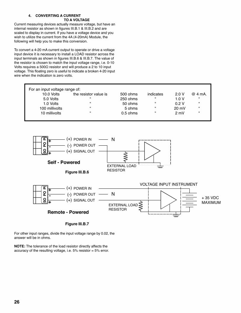
4. CONVERTING A CURRENT TO A VOLTAGECurrent measuring devices actually measure voltage, but have an internalresistorasshowninfiguresIII.B.1&III.B.2andare scaled to display in current. If you have a voltage device and you wish to utilize the current from the 4A (4-20mA) Module, the following will help you to make this conversion.
To convert a 4-20 mA current output to operate or drive a voltage input device it is necessary to install a LOAD resistor across the inputterminalsasshowninfiguresIII.B.6&III.B.7.Thevalueof the resistor is chosen to match the input voltage range, i.e. 0-10 Voltsrequiresa500Ωresistorandwillproducea2to10input voltage.Thisfloatingzeroisusefultoindicateabroken4-20input wire when the indication is zero volts.
For other input ranges, divide the input voltage range by 0.02, the answer will be in ohms.
NOTE: The tolerance of the load resistor directly affects the accuracy of the resulting voltage, i.e. 5% resistor = 5% error.
26
For an input voltage range of: 10.0Volts theresistorvalueis 500ohms indicates 2.0V @4mA. 5.0Volts “ 250ohms “ 1.0V “ 1.0Volts “ 50ohms “ 0.2V “ 100millivolts “ 5ohms “ 20mV “ 10millivolts “ 0.5ohms “ 2mV “
Figure III.B.7
(+)(-)
+-
(+) SIGNAL OUTPOWER OUTPOWER IN+
Remote - Powered
VOLTAGE INPUT INSTRUMENT
+ 35 VDCMAXIMUM
N
EXTERNAL LOADRESISTOR
Figure III.B.6
(+)(-)
+-
(+) SIGNAL OUTPOWER OUTPOWER IN+
Self - Powered
N
EXTERNAL LOADRESISTOR
SO P
O P
ISO
PO
PI

C. TEMPERATURE MODULE (Digital Models only)-TP Temperature Module ordered with Monitor/controller.TPO Temperature Module ordered separately includes label # LTEMP. Requires;Separatethree(3)wire1000ΩRTD temperature sensor. NOTE: OEM models require an additional display harness, part number TPMH. See OEM Installation.
1. DESCRIPTIONThe Temperature Module (TPO) gives the Monitor/controller more flexibilityfortheuserbybeinginthesamepackage.The Temperature Module is driven by the main display output and is very simple to install. The Temperature Module and Temperature Sensor SYSTEM utilize a unique 3 wire technique by which errors are greatly reduced. TheTemperatureModulehasitsown0-5VDCoutput.TPO kit comes with all items necessary to install and operate: TP Module; front panel harness with switch, bezel, cap and two O- rings (006 & 008); and TEMPERATURE label (# LTEMP). An alarm/control function may be added to the TP by ordering the THO harness kit.
Specifications±200°C (±200°F Special Order Only)Accuracy: ±0.2 w/ICE ±0.5 w/out ICEDisplay Resolution = 0.1Output: 0-5VDC Connections-2SensorInput: Separate1000ΩRTDtemperaturesensor.Connections: Three (3) wire for increased accuracy over long distances).
Calibration ZeroandFullScale,FS(0&5VDC):FactorySet SimplepotsDisplay (CAL): Full Scale, FS (199.9) Factory Set Simple pot Operatesonsafe±5VDCsuppliedbytheMainCB.
2. INSTALLATIONBriefly-The Temperature Module replaces the plastic display retainer plate attached to the front panel. The display harness plugs into the Temperature Module instead of the display. The sensor leads are connected to the Temperature Module. See figureIII.C.1.The display switch is installed in the upper front panel as shown in figureIII.C.4.A “TEMPERATURE” label is added to upper front panel next to the DisplaySelectswitchasshowninfigureIII.C.4.
WARNING: BEFORE STARTING, IF MONITOR/ CONTROLLER IS INSTALLED, ENSURE THE POWER IS OFF. FAILURE TO DO SO COULD CAUSE DAMAGE TO THE INSTRUMENT, AND COULD BE HARMFUL OR FATAL TO PERSONNEL. ONLY QUALIFIED PERSONNEL SHOULD INSTALL OR SERVICE ELECTRICAL EQUIPMENT.
PhysicalIf the front panel has all ready been removed from the enclosure skip to 3.
1. Using a standard slot screwdriver remove the screws on the front panel. 2. Carefully wiggle the front panel to loosen the gasket and pull gently toward you. Do not pull more than about 8 inches/20CM or you could damage the wiring harness. 3. Turn the front panel around so that the back side is facing you. 4. Using a standard slot screwdriver remove the four (4) screws holding the plastic display retainer plate to the front panel. When the screws have been removed, the plastic display retainer plate and the display will be free from the front panel.
27
Figure III.C.1
DISPLAY SWITCH (UPPER FRONT PANEL)
TEMPCONTROL
FSZERODISSP2 HYS2
DISPLAY CONNECTION
DISPLAYSELECT
TEMPSENSOR
0-5VDC OUTPUT(-)
(+)
BRNBLU
+
-0- 5VDC
SPC
TEMPCONTROLHARNESS
TEMPERATURESENSOR INPUT
OrangeBlueBrown
RECONNECT DISPLAY HARNESSHERE
DISPLAY IS ON THEBACK SIDE OF THETEMPERATURE MODULE
JUMPER
OR
INCINC
DEC
DEC
TP/TPO - TEMPERATURE MODULE
BR
BL
OR
-
+
DISPLAY
! CAUTION - READ FOLLOWING CAREFULLY

5. Set front panel down or carefully allow to hang from the harness. Do not drop as the harness connector will pull out allowing the front panel to fall. 6. While holding the display and the plastic display retainer plate, carefully remove the display harness connector. Do not drop the display. 7. Remove and discard the plastic display retainer plate. 8. Insert display connector pins into the Temperature Modulefemaleconnector.SeefigureIII.C.1. 9. While holding the front panel, align the display to the opening and at the same time, align the Temperature Module mounting holes to the front panel. 10. Reconnect display harness with leads down as shown in figuresIII.C.1&III.C.2. 11. Reinstall the four (4) screws and tighten.
Display Select Switch installation 1. Using a small sharp knife or 1/4” (6.35mm) drill, carefully cut open the hole on the right side of the front panel, when viewed from the back, just below the Sensor connectorsontheTemperaturemodule.Seefigure III.C.2. 2. Install push-button display switch into this hole and tightenbezel.SeefiguresIII.C.2&III.C.4. 3. Install push-button/cap on switch. WARNING: There are two (2) O-rings installed on the switch, one (1) on the threaded shank and the other is under the push button. Both of these must be re-installed to maintain IP65/NEMA 4X ratings.SeefigureIII.C.3. 4. Place “TEMPERATURE” label next to the switch. See figureIII.C.4.
Electrical 1. Connect the display switch harness to the Temperature ModuleasshowninfigureIII.C.1. 2. Connect the Temperature Sensor leads to the TemperatureModuleaslabeledinfigureIII.C.1.
CAUTION: The sensor input connectors require only a small
screwdriver or a pen to push on the release levers. The release levers may be broken or damaged if not pushed straight toward the CB. DO NOT push the release levers sideways. Follow the color code as labeled.
3. Connect0-5VDCoutput,ifdesired. 4. To test, turn power ON. 5. Press “TEMPERATURE” front panel switch, display will show the temperature of the sensor. 6. Turn power OFF. 7. Continue or reinstall the front panel and tightly secure retaining screws, see REASSEMBLY, page 31.
3. RECALIBRATION Electronic Calibration Only. For System Calibration, see below.The Temperature Module was calibrated at the factory, however, if you wish to check the calibration the following procedure will help you to accomplish this task. Exercise caution while performing this procedure. Requirements: TP Calibration Module (TPC) or Two .1% precision resistors - ZERO-1000.0Ω(0°C=0.0V) SPAN-1758.56Ω(200°C=5.0V) One (1) jumper ADVMsettoDCVolts,atweakerorsmallstandardslot screwdriver.
28
Figure III.C.2
FRONT PANELRear View
LOW
Cut front label out for Display Select Switch here
FSZERODISSP2 HYS2
DISPLAY CONNECTION
TP/TPO - TEMPERATURE MODULE
DISPLAYSELECT
TEMPCONTROLHARNESS
DISPLAY SWITCH (UPPER FRONT PANEL)
DISPLAY
TEMPSENSOR
TEMPERATURESENSOR INPUT
0-5VDC OUTPUT(-)
(+)
BRNBLU
+-0-5VD
DEC
DEC
INCINC
SPC
BR
BL
OR
-
+
Figure III.C.4FRONT PANEL
TEMPERATURELabel Location
720II MYRON LCOMPANY
LOW
HIGHLOW
SET POINT
TEMPERATURESwitch Location
ORP
TEMPERATURE
SWITCH
FRONT PANEL
BEZEL PUSH BUTTON
O-RING O-RING
SWITCH and O-RING ASSEMBLYFigure III.C.3

a. TPC “Calibration” Module ProcedureThis procedure assumes the front panel is removed. 1. Ensure power is OFF. 2. Remove the sensor leads from the Temperature Module. 3. Removethe0-5VDCleadsfromtheTemperatureModule. 4. Press TP Calibration Module (TPC) firmly into sensor inputconnectorsasshowninfigureIII.C.5. 5. AttachtheDVMtothe0-5VDCoutputontheTPC module.SeefigureIII.C.5. 6. Turn power ON.TheDVMshouldindicate0.0 volts. 7. If not, adjust the calibration control marked “ZERO” (see figureIII.C.1forlocation)untiltheDVMindicates0.0 voltsas showninfigureIII.C.5. 8. PressswitchontheTPC.SeefigureIII.C.6. 9. TheDVMshouldindicate5.0volts.SeefigureIII.C.6. 10. If not, while pressing the TPC Module switch, adjust the calibration control marked “FS”(seefigureIII.C.1for location)untiltheDVMindicates5.0voltsasshownin figureIII.C.6. 11. Press the front panel TEMPERATURE select switch and the TPC Module switch, the display should indicate 199.9asshowninfigureIII.C.7. 12. If not adjust the calibration control marked “DIS” (see figureIII.C.1forlocation)untilthereadingis199.9 as showninfigureIII.C.7. 13. Calibration is complete. 14. Turn power OFF. 15. Remove TPC Module by pressing on each Phoenix connector release arm*. 16. Reconnect sensor leads as labeled. 17. Reconnect0-5VDCoutputleadsaslabeled. 18. Continue or reinstall the front panel and tightly secure retaining screws, see REASSEMBLY, page 31.
CAUTION:Thesensorinputand0-10VDCoutputconnectorsrequire only a small screwdriver or a pen to push on the release levers. The release levers may be broken or damaged if not pushed straight toward the CB. DO NOT push the release levers sideways.
b. Precision Resistor Calibration ProcedureThis procedure assumes the front panel is removed. 1. Ensure power is OFF. 2. Remove the sensor leads from the Temperature Module. 3. InstallZEROresistor(1000.0Ω)acrosssensorterminals BLandOR.SeefigureIII.C.8. 4. InstallJUMPERbetweenBR&BLasshowninfigures III.C.8 & III.C.9. 5. AttachtheDVMtothe0-5VDCoutput.SeefiguresIII.C.8 & III.C.9. 6. Turn power ON.TheDVMshouldindicate0.0 volts. 7. If not, adjust the calibration control marked “ZERO” (see figureIII.C.1forlocation). 8. InstallSPANresistor(1758.56Ω)acrosssensor terminalsBLandOR.SeefigureIII.C.9. 9. TheDVMshouldindicate5.0 volts. 10. If not, adjust the calibration control marked “FS” (see figureIII.C.1forlocation)untiltheDVMindicates5.0 voltsasshowninfigureIII.C.9. 11. Press the front panel TEMPERATURE select switch, the display should indicate 199.9asshowninfigure III.C.10. 12. If not adjust the calibration control marked “DIS” (see figureIII.C.1forlocation)untilthereadingis199.9. 13. Calibration is complete. 14. Turn power OFF. 15. RemoveDVMfrom0-5VDC. 16. Remove resistor and jumper by pressing on each Phoenix connector release arm*. 17. Reconnect sensor leads as labeled. 18. Reconnect0-5VDCoutputleadsaslabeled.
29
Figure III.C.5
DV
-+
0.0
Press TPC Module into TPO connector as shown.Press TPC Module into TPO connector as shown.
Connect DVM leads as shown.
BR BL OR - +
TPC ModulePRESS BUTTON FOR
199.9ºC/5.0VDC
MYRON L
BLUEBROWN
OU
TPUT -
0-5VDC
+
OR
AN
GE
BR
OW
NB
LUE
COMPANY
Figure III.C.6
DV
-+
5.0
Press TPC Module into TPO connector as shown.Press TPC Module into TPO connector as shown.
Connect DVM leads as shown.
BR BL OR - +
TPC ModulePRESS BUTTON FOR
199.9ºC/5.0VDC
MYRON L
BLUEBROWN
OU
TPUT -
0-5VDC
+
OR
AN
GE
BR
OW
NB
LUE
COMPANY
Figure III.C.7
199.9FRONT PANEL DISPLAY

19. Continue or reinstall the front panel and tightly secure retaining screws, see REASSEMBLY, page 31.
CAUTION:Thesensorinputand0-5VDCoutputconnectorsrequire only a small screwdriver or a pen to push on the release levers. The release levers may be broken or damaged if not pushed straight toward the CB. DO NOT push the release levers sideways.
c. System CalibrationBy following these steps the complete temperature system, module and sensor, may be calibrated to better than ±0.2° centigrade accuracy. This procedure is similar to the electronic calibration except the sensor is attached and is allowed to equilibrate in “ICE” water before adjusting the ZERO calibration control. NOTE: One of the above electronic calibration procedures, TPC Module or precision resistors, must be performed BEFORE the system calibration is performed. This is required to preset the span between zero and full scale.
1. Ice must be crushed in water to form a very thick slurry. A slurry is that condition where the water to ice ratio is suchthatonlysufficientwaterispresenttoalloweasy stirring. At this point, the temperature of the water will be 0.000°C. 2. Immerse sensor and cable approximately 2” (50mm) into
slurry. 3. Allow to equilibrate. Slurry must be constantly stirred. 4. Continue stirring until no further change in temperature is observed on the display. 5. Adjust TP Module ZERO calibration control to 000.0. 6. Continue or reinstall the front panel and tightly secure retaining screws, see REASSEMBLY, page 31.
4. ALARM/CONTROL FUNCTIONYou have now completed the installation and set up of your Myron L Temperature Module option. Continue to set up and adjust the control feature of the Temperature Module option (-TH/THO & -SC/SCO), if installed.The following assumes the TH/THO option has been installed at the same time as the Temperature Module.
a. Set Point Conversion (SPC) / Reversing Set PointAs shipped from the Myron L® Company your Temperature controllerisconfiguredtoALARM/controlwhenthetemperatureis to TOO HIGH. As many uses require the temperature to be controlled by the use of a heater or chiller, the TPO Module may beconfiguredtomaintainanelevatedorloweredtemperatureas required.Iftheconfigurationiscorrectforyourrequirementsskip to Temperature Set Point Adjust. To reverse the set point ALARM/control operation:
1. Ensure power is OFF. 2. LocatetheSPConTP/TPOcircuitboard.Seefigures III.C.1 & III.C.11. 3. Make a note of the current orientation of the SPC jumpers. 4. Remove both jumpers. This is easily done by hand. Take care not to crush the jumpers if using pliers. 5. Rotate the jumpers 1/4 turn (90°) and reinstall them on theirpostsasshowninfigureIII.C.12. 6. Continue with Set Point adjustment.
30
Figure III.C.8
DV
-+
0.0
JUMPER
BR BL OR - +
Connect DVM leads as shown.
1000.0Ω RESISTOR
Figure III.C.9
DV
-+
5.0
JUMPER
BR BL OR - +
Connect DVM leads as shown.
1758.56Ω RESISTOR
Figure III.C.10
199.9FRONT PANEL DISPLAY
Figure III.C.11
FS
INCINC
TEMPCONTROLHARNESS
DETAIL OF SET POINT CONVERSION (SPC)ON TP/TPO MODULE AS CONFIGURED WHEN SHIPPED FROM THE MFR.
SET POINT CONVERSION (SPC)
DEC
DEC
SPC

b. Temperature Set Point Adjust 1. Ensure power OFF. 2. Ensure the SCO Module Set Point control is set to FULL counter clockwise position. If not, turn SCO Set Point control fully CCW - it may be 30 turns - or until it clicks. ForlocationseefigureIII.C.13. 3. Turn power ON. 4. Press BOTH the Temperature Select switch and the Set Point switch on the front panel. 5. Adjust the TP/TPO Module Set Point Two (SP2) to temperatureasdesired.SeefigureIII.C.1. 6. Turn power OFF.
c. Hysteresis Hysteresisisfixedat~±6°CunlessSpecialOrderedwith adjustable control. Hysteresis with adjustable control is variable from ±0.6 to 6°C, seefigureIII.C.1forlocation.
CAUTION: Adjusting the hysteresis too narrow may cause the alarmtofluctuate(on-off)duetotemperaturevariationscausingthe relay to chatter. This condition is to be avoided, it may damage the heater, chiller, etc. and will eventually damage the relay.
REASSEMBLY 1. Carefullyreinstallthefrontpanel,bottomfirst.Ensureno wires have been pinched between enclosure and front panel. 2. Reinstall the screws and tighten. 3. To operate, turn power ON.
31
FS
INCINC
TEMPCONTROLHARNESS
SET POINT CONVERSION (SPC)
DEC
DEC
SPC
Figure III.C.12
SPCINC
PA
SCO SET POINT #2 ADJUST(TURN CONTROL FULL CCW)
CM
NO
NC
Figure III.C.13
SC/SCO MODULE(SECOND ALARM/CONTROL)
MAIN CIRCUIT BOARD NOT SHOWN FOR CLARITY
COMRELAY #2NO
NC

5. OEM INSTALLATIONAn OEM installation requires an additional display harness, part number TPMH. This harness is installed between the Temperature ModuleandthepaneldisplayasshowninfigureIII.C.14.Both connectors must be installed with the wires down or toward the bottom of the circuit board.
32
MYRON LCOMPANY
DISPLAY SWITCH (FRONT PANEL)
0-5VDCOUTPUT(-)
(+)
TEMPERATURESENSOR INPUT
OrangeBlueBrown
PANEL MOUNTED DISPLAYREAR VIEW
Figure III.C.14
BK WT RD GN NU R- R+
FSZERODISSP2 HYS2
CONNECTMAINCIRCUITBOARDDISPLAY HARNESSHERE
CONNECTFRONTPANELDISPLAYHARNESS(TPMH)HERE
DISPLAY CONNECTION
DISPLAYSELECT
TEMPSENSOR
BRN
BR
BL
OR
-
+
BLU
+0-5VDC-
INCINC
DEC
DEC
TEMPCONTROLHARNESS
JUMPER
ORC
HS
GN
D
UP
HYS1SP1
FUSE*115/ 230
3S
PAR
A
DEC
SPC
TRANSFORMER
Main CB Assembly
0-10VDCOUTPUT
721 726722 727723 728724 729
PWR C GD NC NO CM
TP/TPO - TEMPERATURE MODULE
REM
OVE
TO
INST
ALL
SEC
ON
D R
ELAY
SPC
7 pH/ZERO mVPUSH TO TEST
SET POINT#1 CONTROL
SET POINT #1HYSTERESISRIGHT INCLEFT DEC
SPAN (GAIN)PUSH TO TEST
ZERO SPAN
ORP ZERO
DISINC
SPA
N
CONFIGURATION
pH
MODULE
ZERO
DO NOT ADJUST
DISPLAY CONNECTION

6. OEM INSTALLATIONb. Dual Display Models SPECIAL ORDER These models allow simultaneous display of both Cond/TDS, RES or pH/ORP and Temperature. They require two display harnesses. The Cond/TDS, RES or pH/ORP display harness is part number DH2DD without control feature, or part number DHDD with control feature. The Temperature display harness is part number TPMH.
The DH2DD or DHDD is a “Y” harness that is connected from the main CB to the Cond/TDS, RES or pH/ORP display while the other endisconnectedtotheTemperatureModuleasshowninfigure III.C.15.
The Temperature Module display harness TPMH connects to a separateTemperaturedisplay,thesameasinfigureIII.C.15.
33
MYRON LCOMPANY
TP/TPO - TEMPERATURE MODULE
7 pH/ZERO mVPUSH TO TEST
SET POINT#1 CONTROL
SET POINT #1HYSTERESISRIGHT INCLEFT DEC
SPAN (GAIN)PUSH TO TEST
PANEL MOUNTED DISPLAYREAR VIEW
Figure III.C.15
CH
S
GN
D
UP
FUSE*115/ 230 PWR C GD NC NO CM
BK WT RD GN NU R- R+
3S
PAR
A
DEC
SPC
Main CB Assembly
0-10VDCOUTPUT
TRANSFORMER
FSZERODISSP2 HYS2
DISPLAY CONNECTION
DISPLAYSELECT
INCINC
DEC
DEC
TEMPCONTROLHARNESS
CONNECTMAINCIRCUITBOARDDISPLAYHARNESSHERE
JUMPER
CONNECTFRONTPANELDISPLAYHARNESS(TPMH)HERE
TEMPSENSOR
(-)(+)
BRNBLU
BR
BL
OR
-
+ +0-5VDC-
OR
COND/TDS , RES or pH/ORPDISPLAY
DISPLAY CONNECTION
TEMPERATUREDISPLAY
REM
OVE
TO
INST
ALL
SEC
ON
D R
ELAY
SPC
pH
CONFIGURATIONMODULE
721 726722 727723 728724 729
DO NOT ADJUST
HYS1SP1
SPA
N
ZEROORP ZERO
DISINC
ZERO SPAN
DISPLAY CONNECTION

D. ALARM/CONTROL KIT (Digital & OEM Models only) -TH Controller wiring Harness (requires second alarm/control module) ordered with Monitor/controller.THO Controller wiring Harness (requires second alarm/control module) ordered separately.
1. DESCRIPTIONTheoptionalTH/THOControllerKitaddsmoreflexibilityto the Temperature Module by adding the ability to Alarm and/or Control usingthe24VDCsolidstateoutputtodriveaPA-Piezoelectric alarm, and/or a 10 amp relay to operate a heater or chiller as required.
Kit includesTHO kit comes with all items necessary to install and operate: Alarm/control Harness (replaces second alarm/control relay harness) with switch, bezel, cap and two O-rings (006 & 008); and TEMPERATURE label (# LTEMP).
Requirements -SC/SCO Alarm/Control Module (#2 set point/relay) option -TP/TPO Temperature Module optionThe TH/THO uses SC/SCO Second alarm/control Module on Main circuitboard[Conductivity/TDS,Resistivity,pHormV(ORP)].
2. INSTALLATIONBriefly-The SCH (switch and LED) harness is removed from the SC and front panel, and discarded.The THO harness is installed to the SC, TPO or other controllable option, and front panel. A label is installed on the front panel.
WARNING: BEFORE STARTING, IF MONITOR/ CONTROLLER IS INSTALLED, ENSURE THE POWER IS OFF. FAILURE TO DO SO COULD CAUSE DAMAGE TO THE INSTRUMENT, AND COULD BE HARMFUL OR FATAL TO PERSONNEL. ONLY QUALIFIED PERSONNEL SHOULD INSTALL OR SERVICE ELECTRICAL EQUIPMENT.
PhysicalFirst, you must decide which location to install the THO harness LED and Set Point switch. This is easily determined by how the Primary or the Main CB Alarm/control is used. If the Primary Alarm/control is used as a HIGH control, as in Conductivity, than the THO harness is installed in the lower location - see section III.D.2.a., this page, top of the next column.
If your Primary or Main circuit board Alarm/control is used as a LOW control, as in Resistivity, than the THO harness is installed in the HIGH location — see section III.D.2.b, page 35, halfway down the second column.
WARNING: Before installing switch keep in mind there are two (2) O-rings installed on each switch, one (1) on the threaded shank and the other is under the push button. Both of these must be reinstalled properly to maintain IP65/NEMA 4X ratings, see figureIII.D.4.
a. HIGH Primary ControlIf the front panel has all ready been removed from the enclosure skip to step 3.
1. Using a standard slot screwdriver remove the screws on the front panel. 2. Carefully wiggle the front panel to loosen the gasket and pull gently toward you. Do not pull more than about 8 inches/20CM or you could damage the wiring harness. 3. Remove SCH harness from front panel and SC/SCO Second Alarm/Control Module. a. Carefully remove the RED LED from the front panel
34
FRONT PANELRear View
REMOVEPRIMARYRED LED
REMOVEPRIMARY SET POINT SWITCH
Green LED
LOW
REMOVESC/SCOSET POINT SWITCH andRED LED
FSZERODISSP2 HYS2
DISPLAY CONNECTION
DISPLAYSELECT
TEMPCONTROLHARNESS
DISPLAY
BRNBLU
+0-5VD-
INCINC
TEMPSENSOR
TP/TPO - TEMPERATURE MODULE
DEC
DEC
BR B
L O
R -
+
SPC
Figure III.D.1
! CAUTION - READ FOLLOWING CAREFULLY
720 II
HIGH
LOWSET POINT
FRONT PANELFigure III.D.2
ROUND BEZEL NUTS
TEMPERATURE
pH
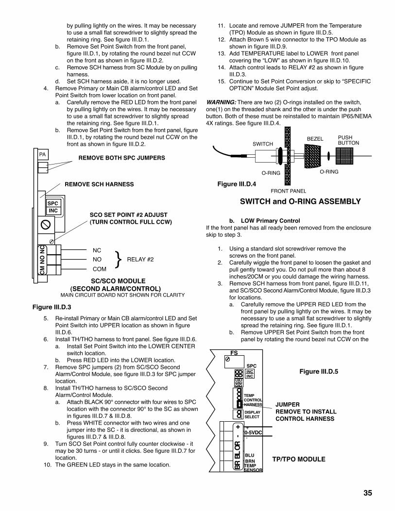
by pulling lightly on the wires. It may be necessary touseasmallflatscrewdrivertoslightlyspreadthe retainingring.SeefigureIII.D.1. b. Remove Set Point Switch from the front panel, figureIII.D.1,byrotatingtheroundbezelnutCCW onthefrontasshowninfigureIII.D.2. c. Remove SCH harness from SC Module by on pulling harness. d. Set SCH harness aside, it is no longer used. 4. Remove Primary or Main CB alarm/control LED and Set Point Switch from lower location on front panel. a. Carefully remove the RED LED from the front panel by pulling lightly on the wires. It may be necessary touseasmallflatscrewdrivertoslightlyspread theretainingring.SeefigureIII.D.1. b. RemoveSetPointSwitchfromthefrontpanel,figure III.D.1, by rotating the round bezel nut CCW on the frontasshowninfigureIII.D.2.
5. Re-install Primary or Main CB alarm/control LED and Set PointSwitchintoUPPERlocationasshowninfigure III.D.6. 6. InstallTH/THOharnesstofrontpanel.SeefigureIII.D.6. a. Install Set Point Switch into the LOWER CENTER switch location. b. Press RED LED into the LOWER location. 7. Remove SPC jumpers (2) from SC/SCO Second Alarm/ControlModule,seefigureIII.D.3forSPCjumper location. 8. Install TH/THO harness to SC/SCO Second Alarm/Control Module. a. Attach BLACK 90° connector with four wires to SPC location with the connector 90° to the SC as shown infiguresIII.D.7&III.D.8. b. Press WHITE connector with two wires and one jumper into the SC - it is directional, as shown in figuresIII.D.7&III.D.8. 9. Turn SCO Set Point control fully counter clockwise - it maybe30turns-oruntilitclicks.SeefigureIII.D.7for location. 10. The GREEN LED stays in the same location.
11. Locate and remove JUMPER from the Temperature (TPO)ModuleasshowninfigureIII.D.5. 12. Attach Brown 5 wire connector to the TPO Module as showninfigureIII.D.9. 13. Add TEMPERATURE label to LOWER front panel coveringthe“LOW”asshowninfigureIII.D.10. 14. AttachcontrolleadstoRELAY#2asshowninfigure III.D.3. 15. Continue to Set Point Conversion or skip to “SPECIFIC OPTION” Module Set Point adjust.
WARNING: There are two (2) O-rings installed on the switch, one(1) on the threaded shank and the other is under the push button. Both of these must be reinstalled to maintain IP65/NEMA 4Xratings.SeefigureIII.D.4.
b. LOW Primary ControlIf the front panel has all ready been removed from the enclosure skip to step 3.
1. Using a standard slot screwdriver remove the screws on the front panel. 2. Carefully wiggle the front panel to loosen the gasket and pull gently toward you. Do not pull more than about 8 inches/20CM or you could damage the wiring harness. 3. RemoveSCHharnessfromfrontpanel,figureIII.D.11, andSC/SCOSecondAlarm/ControlModule,figureIII.D.3 for locations. a. Carefully remove the UPPER RED LED from the front panel by pulling lightly on the wires. It may be necessarytouseasmallflatscrewdrivertoslightly spreadtheretainingring.SeefigureIII.D.1. b. Remove UPPER Set Point Switch from the front panel by rotating the round bezel nut CCW on the
35
SPCINC
PA
SCO SET POINT #2 ADJUST(TURN CONTROL FULL CCW)
CM
NO
NC
Figure III.D.3
SC/SCO MODULE(SECOND ALARM/CONTROL)
MAIN CIRCUIT BOARD NOT SHOWN FOR CLARITY
COMRELAY #2NO
NC
REMOVE SCH HARNESS
REMOVE BOTH SPC JUMPERS
SWITCH
FRONT PANEL
BEZEL PUSH BUTTON
O-RING O-RING
SWITCH and O-RING ASSEMBLY
Figure III.D.4
BR B
L OR
- +
SPCFigure III.D.5
TEMPCONTROLHARNESS
FS
DISPLAYSELECT
TEMPSENSOR
BRNBLU
INCINC
DEC
DEC
JUMPERREMOVE TO INSTALLCONTROL HARNESS
TP/TPO MODULE
+0-5VDC-

frontasshowninfigureIII.D.2. c. Remove harness from SCO Module by pulling on harness,seefigureIII.D.3. d. Set SCH harness aside, it is no longer used. 4. Remove SPC jumpers (2) from SC/SCO Second Alarm/ControlModule,seefigureIII.D.3forSPCjumper location.
5. InstallTH/THOharnesstofrontpanel,figuresIII.D.12& III.D.13. a. Install THO Set Point Switch to the UPPER CENTER switchlocation,figureIII.D.12,keepinginmindthe “O-ring”warningabove.SeefigureIII.D.4forswitch reassembly. b. Press RED LED into the UPPER location, as shown infigureIII.D.12. 6. InstallTH/THOharnesstoSC/SCO,figuresIII.D.7& III.D.8.
a. Attach BLACK 90° connector with four wires to SPC location with the connector 90° to the SCO as showninfiguresIII.D.7&III.D.8. b. Press WHITE connector with two wires and one jumper into the SCO - it is directional, as shown in figuresIII.D.7&III.D.8. 7. The GREEN LED stays in the same location.
36
FRONT PANELRear View
INSTALL THOHARNESSRED LED
INSTALL THOHARNESS SETPOINT SWITCH
Green LED
LOW
REINSTALLPRIMARYSET POINTSWITCH
REINSTALLPRIMARYRED LED
FSZERODISSP2 HYS2
DISPLAY CONNECTION
DISPLAYSELECT
TEMPCONTROLHARNESS
DISPLAY
BRNBLU
+0-5VD-
INCINC
DEC
TEMPSENSOR
TP/TPO - TEMPERATURE MODULE
DEC
DEC
BR B
L O
R -
+
SPC
Figure III.D.6
TEMPCONTROLHARNESS
FSZERODISSP2 HYS2
DISPLAY CONNECTION
DISPLAYSELECT
SET POINT SWITCH (LOWER FRONT PANEL)
SCO MODULE CONNECTOR (SPC ON SECOND ALARM/CONTROL)
DISPLAY
TEMPSENSOR
BRNBLU
+0-5VDC
INCINC
DISPLAY SWITCH (UPPER FRONT PANEL)
BROWN THO CONNECTOR
TP/TPO MODULE WITH DISPLAY AND TH/THO HARNESS
-
TP/TPO - TEMPERATURE MODULE
Figure III.D.9
SPC
DEC
DEC
BR B
L OR
-
+
SPCINC
PA
SCO SET POINT #2 ADJUST
SCO SET POINT #2 ADJUST
(TURN CONTROL FULL CCW)
CM
NO
NC
Figure III.D.7
SC/SCO MODULE(SECOND ALARM/CONTROL)
MAIN CIRCUIT BOARD NOT SHOWN FOR CLARITY
COMRELAY #2NO
NC
INSTALL THO HARNESS WHITECONNECTOR HERE
INSTALL THO HARNESS BLACK CONNECTOR HERE
Figure III.D.8
WHITECONN
BLACKCONN
PA
SC/SCO MODULE
THO HARNESS

8. Turn SCO Set Point control fully counter clockwise - it maybe30turns-untilitclicks.SeefigureIII.D.7for location. 9. Locate and remove JUMPER from option to the TPO ModuleasshowninfigureIII.D.5. 10. Attach Brown 5 wire connector to option to be controlled, i.e.TPOModuleasshowninfigureIII.D.9.
11. Add TEMPERATURE label to UPPER front panel coveringthe“HIGH”asshowninfigureIII.D.13. 12. AttachcontrolleadstoRELAY#2asshowninfigure III.D.7. 13. Continue to Set Point Conversion or skip to “SPECIFIC OPTION” Module Set Point adjust.
37
720 II
HIGH
SET POINT
FRONT PANELFigure III.D.10
TEMPERATURELABELLOCATION
TEMPERATURE
ORP
TEMPERATURE
TEMPERATURE
FRONT PANELRear View
PRIMARY RED LED
PRIMARY SETPOINT SWITCH
Green LED
LOW
REMOVESC/SCOSET POINTSWITCHandRED LED
FSZERODISSP2 HYS2
DISPLAY CONNECTION
DISPLAYSELECT
TEMPCONTROLHARNESS
DISPLAY
BRNBLU
+0-5VDC-
INCINC
TEMPSENSOR
TP/TPO - TEMPERATURE MODULE
DEC
DEC
BR B
L O
R -
+
SPC
Figure III.D.11
FRONT PANELRear View
Primary/Main CB Red LED
Primary/Main CB Set Point Switch
Green LED
LOW
INSTALLTHOSET POINTSWITCHandRED LED
FSZERODISSP2 HYS2
DISPLAY CONNECTION
DISPLAYSELECT
TEMPCONTROLHARNESS
DISPLAY
BRNBLU
+0-5VDC-
INCINC
DEC
TEMPSENSOR
TP/TPO - TEMPERATURE MODULE
DEC
DEC
BR B
L O
R -
+
SPC
Figure III.D.12
720 II
LOWSET POINT
FRONT PANELFigure III.D.13
TEMPERATURELABELLOCATION
TEMPERATURE
ORP
TEMPERATURE
TEMPERATURE

Set Point Conversion (SPC) / Reversing Set PointThe Myron L® Company ships the Temperature controller configuredtoAlarm/controlwhenthetemperatureisTOOHIGH.If theconfigurationiscorrectforyourrequirementsskipto Temperature Set Point Adjust. As many uses require the temperature to be controlled by the useofaheaterorchiller,theTPOModulemaybeconfiguredto maintain an elevated or lowered temperature as required.
To reverse the set point/relay operation: 1. LocatetheSPConTP/TPOcircuitboard.Seefigures III.D.8 & III.D.14. 2. Remove Jumpers. 3. ReinstallJumpers90°asshowninfigureIII.D.15.
FOR TEMPERATURE MODULETemperature Set Point Adjust 1. Ensure the SCO Module Set Point control is set toFULLCCWposition.ForlocationseefigureIII.D.7. 2. Press BOTH the Temperature Select switch and the Set Point switch on the front panel. 3. Adjust the TP/TPO Module Set Point Two (SP2) totemperatureasdesired.SeefigureIII.D.9.
Hysteresisisfixedat~±6°CunlessSpecialOrderedwith adjustable control. Hysteresis with adjustable control is variable from ±0.6 to 6°C.
CAUTION: Adjusting the hysteresis too narrow may cause the alarmtofluctuate(on-off)duetotemperaturevariationscausingthe relay to chatter. This condition is to be avoided, it may damage the heater, chiller, etc. and will eventually damage the relay.
REASSEMBLY 1. Carefullyreinstallthefrontpanel,bottomfirst. Ensure no wires have been pinched between enclosure and front panel. 2. Reinstall the screws and tighten. 3. To operate, turn power ON.
38
Figure III.D.14
FS
INCINC
TEMPCONTROLHARNESS
DETAIL OF SET POINT CONVERSION (SPC)ON TP/TPO MODULE AS CONFIGURED WHEN SHIPPED FROM THE MFR.
SET POINT CONVERSION (SPC)
DEC
DEC
SPC
Figure III.D.15
FS
INCINC
TEMPCONTROLHARNESS
SET POINT CONVERSION (SPC)
DEC
DEC
SPC

E. DUAL TEMPERATURE MODULE & 4-20mA OUTPUT MODULE (Digital and OEM Models ONLY) -TP/TPO Temperature Module.-4A/4AO 4-20mA Self/Remote-powered Isolated output module.
1. DESCRIPTIONThe following instructions describe how install BOTH the 4A/4AO and the TP/TPO Modules to a Digital model Monitor/controller.
SpecificationsSee individual Data Sheets and installation instructions.
Requires Plastic Spacers P# SP4819.
2. INSTALLATIONBriefly-The Temperature Module replaces the plastic display retainer plate attached to the front panel as described in Temperature Module Installation Instructions except threaded plastic spacers are utilized in place of the screws. The 4AO Module is STACKED on top of the TPO Module utilizing abovespacersasshowninfigureIII.E.1.Setup and operation for both modules is the same as described in their respective Data Sheet/Installation Instructions.
WARNING: BEFORE STARTING, IF MONITOR/ CONTROLLER IS INSTALLED, ENSURE THE POWER IS OFF. FAILURE TO DO SO COULD CAUSE DAMAGE TO THE INSTRUMENT, AND COULD BE HARMFUL OR FATAL TO PERSONNEL. ONLY QUALIFIED PERSONNEL SHOULD INSTALL OR SERVICE ELECTRICAL EQUIPMENT.
This procedure assumes the front panel is removed, and the TP/TPO has already been installed.
1. InstallspacersasshowninfigureIII.E.1. 2. Attach4AOModulefive(5)wireharness,andsignal and power wires as required as described in 4AO Data Sheet/Installation Instructions. 3. Carefullyreinstallthefrontpanel,bottomfirst. Ensure no wires have been pinched between enclosure and front panel. 4. Reinstall the screws and tighten. 5. To operate, turn power ON.
39
! CAUTION - READ FOLLOWING CAREFULLY
FRONT PANELLEFT SIDE VIEW
PLASTICSPACERS (4)
TP/TPO
4A/4AO
SCREWS
Figure III.E.1

40
F. PIEZO ELECTRIC ALARM -PA Piezo Electric Alarm ordered with Digital Monitor/controller.PAO Piezo Electric Alarm ordered separately for Digital or remotely mounted Analog Monitor/controller or OEM models.
1. DESCRIPTIONThe PA/PAO is an electronic sound device capable of emitting a 80dBormore@30cm,highpitchedsqueal.SeefigureIII.F.1.
Specifications OscillatingFrequency—3.0≠0.5KHz OperatingVoltage(750II)—24VDCNom.(1.5-30VDCMax.) SoundPressureLevel(Min)30cm/12VDC—80dB Currentconsumption(Max)@12VDC—12mA Tone — Constant Operating Temperature — -20 - +60°C Size — 24 x 9.5 mm
2. INSTALLATIONBriefly-The PA/PAO Piezo Alarm attaches to the front panel with the tape supplied,seefigureIII.F.3.The wire harness plugs into a methode connector on the main CB*,seefigureIII.F.4.*MayalsobeconnectedtotheSCModuleasshowninfigureIII.I.5, if desired or so equipped.
WARNING: BEFORE STARTING, IF MONITOR/ CONTROLLER IS INSTALLED, ENSURE THE POWER IS OFF. FAILURE TO DO SO COULD CAUSE DAMAGE TO THE INSTRUMENT, AND COULD BE HARMFUL OR FATAL TO PERSONNEL. ONLY QUALIFIED PERSONNEL SHOULD INSTALL OR SERVICE ELECTRICAL EQUIPMENT.
PhysicalNOTE: Remote mounting will require a .25” (6.35mm) hole, and extending the harness. Use #22 gauge speaker wire. Observe polarity.If the front panel has all ready been removed from the enclosure skip to #4.
1. Using a standard slot screwdriver remove the
screws on the front panel. 2. Carefully wiggle the front panel to loosen the gasket and pull gently toward you. Do not pull more than about 8 inches/20CM or you could damage the wiring harness. 3. Turn the front panel around so that the back side is facing you. 4. Using a 1/4” drill or a sharp knife, carefully open the CENTERfrontholeinthefrontpanelasshowninfigure III.F.2. 5. Peal off tape backing from PA, and install between guidesasshowninfigureIII.F.3. 6. Set front panel aside. 7. ConnectwireharnesstoMainCBasshowninfigure III.F.4,ortoSCasshowninfigureIII.F.5.
Test 1. To test, simply turn ON the controller and adjust controller set point until the alarm sounds off. NOTE: If the sensor is connected, the solution value, set point value and Set Point Conversion (SPC) jumpers may affect the test. 2. Turn power OFF.
! CAUTION - READ FOLLOWING CAREFULLY
Figure III.F.1
Double Backed Tape
Harness ~9"
Piezo Alarm Methode Connector
Figure III.F.2
FRONT PANELRear View
CUT OPENTHIS HOLE

41
REASSEMBLYBefore reassembly, ensure set point control is set to desired trip point. 1. Carefullyreinstallthefrontpanel,bottomfirst.Ensureno wires have been pinched between enclosure and front panel. 2. Reinstall the screws and tighten. 3. To operate, turn power ON.
MYRON LCOMPANY
HYS1SP1
SPA
N
ZERO
7 pH/ZERO mVPUSH TO TEST
SET POINT#1 CONTROL
SET POINT #1HYSTERESISRIGHT INCLEFT DEC
SPAN (GAIN)PUSH TO TEST
PA Connection(may use eitherconnector)
Figure III.F.4
CH
S
GN
DFUSE*115/ 230
UP
ZERO SPAN
3SPA
RA
DEC
SPC
MAIN CB ASSEMBLY
Figure III.F.3
FRONT PANELRear View
Red LED(s)GreenLED
PiezoAlarm
Guides (4)
Figure III.F.5
OR
SC MODULEMain CB NOT shown for clarity
PA
PWR C GD NC NO CM CM
NO
NC
BT WT RD GN NU R- R+
TRANSFORMER
ORP ZERO
DISINC
pH
721 726722 727723 728724 729
DO NOT ADJUST
CONFIGURATIONMODULE
REM
OVE
TO
INST
ALL
SEC
ON
D R
ELAY

42
G. REMOTE ALARM - RA™ RA Ordered as an accessory, includes 8” harness with connector, and two (2) wire nuts.
1. DESCRIPTIONThisremotelymountedAUDIBLEandVISUALalarmconnectstoany Myron L® Company Monitor/controller, or brand “X” controller with dry contacts. When activated by the controller the Remote Alarm will provide both an audible and a visual alert at a location other than at the controller.
A mute button will silence the piezo alarm for up to 10 minutes while the LED remains illuminated. After the preset time the piezo alarm will again sound, this will repeat until the water quality is corrected. Thus allowing servicing of the system under control, while still acting as a reminder if the problem has not been corrected.
The Remote Alarm - RA™ is an inexpensive way to alert personnel of a trouble situation. For example; the Monitor/controller may be located with an RO system while the service technicians are on anotherfloororeveninanotherbuilding-greatforhospitals.The AUDIBLE alarm may be silenced, but stays in alarm (RED LED is still illuminated) until the trouble is corrected. The timer may be set from 15 seconds up to 10 minutes, thereby, giving personnel the time to correct the problem while not being able to ignore the troublebecauseofthereoccurringAUDIBLEandVISUALalerts.
SpecificationsAudible Alert — Piezo Electric Oscillating Frequency — 3.0±0.5KHz OperatingVoltage(720II)—24VDCNom.(1.5-30VDCMax.) SoundPressureLevel(Min)30cm/12VDC—80dB Currentconsumption(Max)@12VDC—12mA Tone — Constant Operating Temperature — -20 - +60°C Size — 24 x 9.5 mmVisualAlert—BrightREDLEDTime Delay — 15 seconds to 10 minutes (USER adjustable)Power—24VDC(suppliedfromMonitor/controller)Case Material — ABS plasticDimensions — 4.75L x 2.56W x 1.56H (121L x 65W x 40H)Mounting — Double Backed Tape (supplied)Operational Distance — Wire lengths of 500 feet (152 meters) have been tested with no adverse effects Additional Wire available, order RAW-200. — 200 feet (61 meters)
2. INSTALLATIONBriefly—Only 2 wires to connect from the controller to the RA. Set the time.Mount on the wall or on the bench.
WARNING: BEFORE STARTING, IF MONITOR/ CONTROLLER IS INSTALLED, ENSURE THE POWER IS OFF. FAILURE TO DO SO COULD CAUSE DAMAGE TO THE INSTRUMENT, AND COULD BE HARMFUL OR FATAL TO PERSONNEL. ONLY QUALIFIED PERSONNEL SHOULD INSTALL ELECTRICAL EQUIPMENT.
The Remote Alarm - RA connector is labeled 24VDC INPUT and has a 8” 2 conductor wires attached — Black is Positive (+) and White is Negative (-). When extending the wires you may use any two color wire you wish just remember the polarity — Black is Positive (+) and White is Negative (-). Wire lengths of 500 feet/152 meters have been tested and have no adverse effect on performance although a length of 500 feet/152 meters would be unusually long. Ensure the unit is completely wired, tested and adjusted before installing RA to mounting surface as the tape will not remove from mounting surface without damaging the adhesive. For OEM models skip steps referencing enclosure or front panel.
1. Run #22, 2 conductor speaker type wire, NOT supplied, from Monitor/controller to RA location as necessary. Wire may be ordered from the Myron L® Company, part #RAW- 200. 2. Open the RA by removing the four screws. 3. Locate and remove the 8” 2 conductor wire with the reddishbrownconnectorattachedtotheRA.Seefigure III.J.1. 4. At the RA, connect the extension wires to the connector on the RA circuit board — Black to Positive (+) and White toNegative(-)asshowninfigureIII.G.1. 5. Using a standard slot screwdriver remove the screws on the Myron L Monitor/controller front panel. 6. Carefully wiggle the front panel to loosen the gasket and pull gently toward you. Do not pull more than about 8 inches/20CM or you could damage the wiring harness. 7. Connect the extension wires to the 8” 2 conductor wire with the wire nuts provided — Black to Positive (+) and WhitetoNegative(-).Besuretofirstpassthewire through the user supplied waterproof strain relief in the enclosure. 8. Plug the reddish brown connector into the male connector on the controller circuit board marked RA (see insidecaselabelorfigureIII.J.2forlocation).Itwillonly go on the connector one way. 9. To test, simply turn ON the controller and adjust controller set point until the alarm sounds off*. The black button on the front of the RA will mute the piezo alarm for approximately three minutes or until you improve the water quality (readjust controller set point). If threeminutesmutingisfineforyourapplication,skipto #10.
! CAUTION - READ FOLLOWING CAREFULLY
RA CB ASSEMBLY
CONTROLLER+ - 10
4
1530
78
5
9
321
6
MINSEC
Figure III.G.1

43
10. If three minutes is too long or too short, adjust control inside RA until desired mute time is achieved (adjustable from approximately 15 seconds to 10 minutes). see figureIII.G.1. 11. Replace the bottom of the RA, and secure to surface you have selected for its installation. 12. Carefullyreinstallthecontrollerfrontpanel,bottomfirst. Ensure no wires have been pinched between enclosure and front panel. 13. Reinstall the screws and tighten. 14. To operate, turn power ON.
*NOTE: If the RA does not sound off; 1. Check the polarity of the extension wire connections. 2. Be sure the controller is actually switching (relay will click).
MYRON LCOMPANY
HYS1SP1
SPA
N
ZERO
7 pH/ZERO mVPUSH TO TEST
SET POINT#1 CONTROL
SET POINT #1HYSTERESISRIGHT INCLEFT DEC
SPAN (GAIN)
RAConnector
PUSH TO TEST
Figure III.G.2
CH
S
GN
DFUSE*115/ 230
UP
ZERO SPAN
3SPA
RA
DEC
SPC
MAIN CB ASSEMBLY
PWR C GD NC NO CM
BT WT RD GN NU R- R+
TRANSFORMER
ORP ZERO
DISINC
pH
721 726722 727723 728724 729
DO NOT ADJUST
CONFIGURATIONMODULE
REM
OVE
TO
INST
ALL
SEC
ON
D R
ELAY

44
IV. OPERATING PROCEDURESA. FRONT PANELThe front panel illustrations to the right, switch and indicator operational descriptions have been provided to assist the user in identifying and operating the 720 Series II Monitor/controllers.For OEM models see Section B. RefertoSectionIV.CforSetupproceduresandSectionIV.DforCheck-Out procedures.
1. RED “HIGH SET POINT” LED INDICATORTheredLEDindicatorlightisONonlywhenthewater’spHorORP readingisHIGHorABOVEthesetpointadjustment.Maybe reversed if desired.
2. GREEN “LOW SET POINT” LED INDICATORThegreenLEDindicatorlightisONonlywhenthewater’spHorORP reading is LOW or BELOW the set point adjustment. May be reversed if desired.
3. “SET POINT” SWITCH(ES)When the “SET POINT” switch is depressed, the internal set point reading is immediately displayed on the front panel display. See figuresIV.A.1thru4.
4. ANALOG METER OR DIGITAL LCD Front panel analog meter or digital display provide a continuous readout of the water being monitored.
pH Models 721II & 722II and ORP Models 726II & 727II are equippedwithanalogmeteronly.SeefiguresIV.A.4&5.
pH Models 723II & 724II and ORP Models 728II & 729II are equipped with a 3 1/2 digit, 1/2” Liquid Crystal Digital Display, as showninfiguresIV.A.1thru3,witha31/2digitbacklitLCDasan option.
5. OPTIONAL FRONT PANEL ITEMSTP/TPO Module SwitchA digital Monitor controller with the optional TP/TPO Temperature Module, see picture at right, has an additional switch on the front panel. This push-button momentary switch when pushed gives the user a direct reading of the temperature of the solution from 0- 200°C. Additional option TH/THO includes a control function capability. Mounts in the lower left corner of the upper panel, see figureIV.A.1.
7pHorZEROmVTestSwitch(TEST)This optional feature allows the user to see the ZERO TEST value without opening the enclosure to push the internal switch. Mounts inthelowerleftcorneroftheupperpanel,seefigureIV.A.3. unlessorderedwithTPModulethan7pHorZEROmVTestSwitch (TEST)mountsinthelowercenteroftheupperpanel,seefigure IV.A.1.
Piezo AlarmAudible alarm sounds off automatically when the set point is reached.FigureIV.A.3.showsthelocationofthisoption.
Analog pHMonitor/controller(Single Alarm/control)
Digital pH Monitor/controller with optional Dual Alarm/controls
Digital ORP Monitor/controller with optional Front Panel Test Switch, Single Alarm/control, and Piezo Alarm.
Analog ORPMonitor
Digital pH Monitor/controller with optional Dual Alarm/controls, and Temperature with control function, and Front Panel Test Switch.
726II
722II
728II-PTS-PA
723II-SC
723II-SC-TP-THH-PTS
Figure IV.A.1
720II
HIGH
LOWSET POINT
TEMPERATURE
TEMPERATURE
TEST
pH
MYRON LCOMPANY
Figure IV.A.2
720II
HIGH
LOWSET POINT
pH
MYRON LCOMPANY
Figure IV.A.3
HIGHLOW
SET POINT
720II
ORP
TEST
MYRON LCOMPANY
Figure IV.A.4
720II
HIGHLOW
SET POINT
0 1412
62
8 104
pH
MYRON LCOMPANY
Figure IV.A.5
720II
ORP2 2
1.5.5
1.5.5 11
0
X1000
MYRON LCOMPANY

45
B. OEM FRONT PANEL INDICATORS & CONTROLSThe simulated OEM front panel illustrations to the right, and switch and indicator operational descriptions have been provided to assist the OEM user in identifying and operating the 720 Series II Monitor/controllers.
RefertoSectionV.C.forSetupprocedures,andSectionV.D.forCheck-Out procedures.
1. RED “HIGH SET POINT” LED INDICATORTheredLEDindicatorlightisONonlywhenthewater’spHorORP readingisHIGHorABOVEthesetpointadjustment.Maybe reversed if desired.
2. GREEN “LOW SET POINT” LED INDICATORThegreenLEDindicatorlightisONonlywhenthewater’spHorORP reading is LOW or BELOW the set point adjustment. May be reversed if desired.
3. “SET POINT” SWITCH(ES)When the “SET POINT” switch is depressed, the internal set point reading is immediately displayed on the front panel display. See figuresIV.B.1thru4.
4. ANALOG METER OR DIGITAL DISPLAY Panel mounted analog meter or digital display provide a continuous readout of the water being monitored.
pH Models 721II & 722II and ORP Models 726II & 727II are equippedwithanalogmeteronlyasshowninfiguresIV.B.4&5.
pH Models 723II & 724II and ORP Models 728II & 729II are equipped with a 3 1/2 digit, 1/2” Liquid Crystal Digital Display, as showninfiguresIV.B.1thru3.,witha31/2digitbacklitLCDasan option.
5. OPTIONAL PANEL MOUNTED ITEMSTP/TPO Module SwitchA digital Monitor/controller with the optional TP/TPO Temperature Module has an additional switch on the front panel as shown in figureIV.B.1..Thispush-buttonmomentaryswitchwhenpushed gives the user a direct reading of the temperature of the solution from 0-200°C. Additional option TH/THO includes a control functioncapability.SeefigureIV.B.1.
7pHorZEROmVTestSwitch(TEST)This optional feature allows the user to see the ZERO TEST value withoutopeningthepaneltopushtheinternalswitch.Seefigures IV.B.1andIV.B.3fortypicalexamples.
Piezo AlarmAudible alarm sounds off automatically when the set point is reached. Mounted by OEM in any convenient location as shown in figureIV.B.3.
WARNING: THE DISPLAY WILL BE IRREPARABLY DAMAGED IF THE HARNESS IS INSTALLED UPSIDE- DOWN. THE HARNESS MUST BE INSTALLED AS SHOWN IN FIGURE II.E.3.
HIGHLOW
SET POINT
HIGH
LOWSET POINT
LOWSET POINT
TEMPERATURE
TEMPERATURE
TEST
Figure IV.B.1
Figure IV.B.2
Figure IV.B.3
Figure IV.B.4
Figure IV.B.5
HIGHLOW
SET POINT
TEST
NOTE: Boxes around displaysto simulate OEM panels.
0 1412
62
8 104
pH
ORP2 2
1.5.5
1.5.5 11
0
X1000
Analog pHMonitor/controller(Single Alarm/control)
Digital pH Monitor/controller with optional Dual Alarm/controls
Digital ORP Monitor/controller with optional Front Panel Test Switch, Single Alarm/control, and Piezo Alarm.
Analog ORPMonitor
Digital pH Monitor/controller with optional Dual Alarm/controls, and Temperature with control function, and Front Panel Test Switch.
726II
722II
728II-PTS-PA
723II-SC
723II-SC-TP-THH-PTS

46
C. SETUP PROCEDURES These Setup procedures cover (1) converting the alarm circuit to trigger on a decreasing or increasing reading, (2) checking out your new Monitor/controller, (3) setting the alarm circuit set point(s), and (4) adjusting the hysteresis.
The following require that the front panel be removed. While doing so be careful not to strain the cable(s).
NOTE: A small screwdriver or tweaker will be required for several of the following operations.
1. SET POINT CONVERSION (SPC) / REVERSING SET POINTThe alarm/control circuit(s) on all 720 Series II pH/ORP Monitor/controllersareconfiguredtotriggerthealarmrelayasthe reading increases.
Iftheuser’sapplicationrequiresit,thealarmcircuitmaybeeasily reconfiguredtotriggerthealarmrelayasthereadingdecreases. RefertofigureV.A.1.forthelocationsofthejumpersreferredto in this section.
NOTE: These instructions describe the general procedures for converting the Monitor/controller without reference to jumper numbers or orientation.
1. Ensure power is OFF. 2. Locatethejumperblockforthealarmtobeconfigured. 3. Make a note of the current orientation of the jumpers. 4. Remove both jumpers. This is easily done by hand. Take care not to crush the jumpers if using pliers. 5. Rotate the jumpers 1/4 turn and reinstall them on their postsasshowninfigureIV.C.1.
2. CHECK-OUT PROCEDURESThe following check-out procedures are used to verify that the 720 Series II Monitor/controller is operating properly. It is assumed that the Monitor/controller is powered ON, that it is connected to an appropriate Sensor, and that the Sensor is immersed in water within the range that the Monitor/controller will berequiredtoread.RefertofigureV.A.1.forthelocationsofthecomponents referred to in this section.
a. Make a note of the reading on the display. b. Being careful not to strain the connecting cable(s), unfasten and remove the front panel. c. While pressing the ZERO Test Switch (ZERO), verify that thefrontpaneldisplayisindicating7pHor0mVreading.
Ifnot,seeCalibration,sectionV.C. d. Press and hold the “SET POINT” switch on the front panel. Using the tweaker or a small screwdriver, adjust the Set Point trimmer adjustment screw on the circuit boardtosweepthedisplayleftandright1pHunitor60mV on both sides of water reading. Listen for the alarm relay toclick‘ONandOFF’asthealarmsetpointmovespast the water reading. e. Adjust the alarm to the desired set point value. Release the “SET POINT” switch.
NOTE: For Models with SC/SCO module, repeat STEPS 4 & 5 to check out Set Point #2.
3. SET POINT ADJUSTMENTThesetpointsettingisbasedupontheuser’sparticularwaterpurityspecificationsorrequirements.
NOTE: The optional secondrelay/alarmis“stacked”onthefirstrelay/alarm, therefore, when setting the optional second relay/alarmSetPoint,the#1SetPointmustbe‘set’first.
a. Being careful not to strain the cable, unfasten and removetheMonitor’sfrontpanel. b. While depressing the “SET POINT” switch, turn theSetPoint#1adjustmentscrew(SeefigureV.A.1) until the desired set point value is indicated on the display. c. If Hysteresis adjustment is required see below. If not, reinstall the front panel and tightly secure both retaining screws.
4. HYSTERESIS (DEAD BAND) ADJUSTMENTThe hysteresis or dead band is approximately ±3% of the set point at full scale as it leaves the factory. Under normal (most) conditions it will not be necessary to adjust. However, if you desire to make an adjustment please keep the following in mind.The adjustment is very simple and is based on set point location. If the set point* is in the upper 75-100% of the scale, the hysteresis control pot should be turned fully to the right. If the set point is in the lower portion of the scale, i.e. 5-25 % of scale, the control pot may be turned fully to the left. If you are operating in the center, 25-75% of scale, the control pot may be adjusted in the center. Or the hysteresis or dead band may be adjusted to tighten the control of a particular process.
CAUTION: adjusting the hysteresis too tight may cause the alarmtofluctuate(on-off)duetoflow,chemicalmixingorbubbles causing the relay to chatter. This condition is to be avoided, it could damage your valves, pumps, etc. and will eventually damage the relay.
* Applies to both set points if so installed.
The following is assuming the front panel is already removed and the set points have been set, if not see above,
1. Locate the hysteresis control adjustment located next to the Set Point #1 (SP1) adjustment - it is a single turn pot. SeefigureV.A.1. 2. Adjust as described above or as desired. 3. Reassemble per below.
! CAUTION - READ FOLLOWING CAREFULLY
JUMPER CONVERSION Figure C.1
INCREASING DECREASING

47
REASSEMBLY 1. Carefullyreinstallthefrontpanel,bottomfirst.Ensureno wires have been pinched between enclosure and front panel. 2. Reinstall the screws and tighten. 3. To operate, turn power ON.

48
A. PRIMARY COMPONENT IDENTIFICATIONAsidentifiedinSectionIII,theMonitors/controllersswitch(es)and indicator components are mounted directly to the front panel.
The Monitor/controllers main circuit board is contained within and mounted to the back of the enclosure. Some models with options have an additional circuit board mounted behind the front panel, i.e. Model 723II-4A (4-20 Module).
ReviewfigureV.A.1belowtofamiliarizeyourselfwiththeMaincircuit board assembly. The following diagram has the second alarm/control module option installed.
V. COMPONENT IDENTIFICATION, CALIBRATION AND PREVENTIVE CARE
POWER
AC LINE/ +DC
AC NEUTRAL/ -DC
GROUND
Figure V.A.1
SPANZERO
DO NOT ADJUST
RELAY #1COM
NC NO
3SO/3SE SWITCHCONNECTION
DISPLAY/METERCONNECTOR
4-20 CONNECTOR
SET POINT #1CONVERSION
TRANSFORMER
FUSE*115/ 230
ZEROCALIBRATIONCONTROL
SET POINT #2 CONTROL
SC/SCOOPTIONALSECONDALARM/CONTROLMODULE
SET POINT #2CONVERSION
#2 RELAYLIGHTS &SWITCHCONNECTOR
DISPLAY CALIBRATIONCONTROL (FACTORY SET)
RUBBER TAPE (DO NOT REMOVE)
SPCINC
PA
SET POINT#1 CONTROL
INC
SET POINT #1HYSTERESISRIGHT INCLEFT DEC
CHASSIS GROUND - OEM
INC
SET POINT #2 HYSTERESISRIGHT INC / LEFT DEC
3S
SPC
0-10VDC OUTPUT
BLK
WHT
RED
GRN
NEU
(+)SENSOR(-)
+COM
RELAY #2NONC
+
SPAN (GAIN)CALIBRATIONCONTROL
721 726722 727723 728724 729
MYRON L COMPANY
7 pH/ZERO mVPUSH TO TEST
SPAN (GAIN )PUSH TO TEST
CONFIGURATIONMODULE
CONFIGURATION MODULEALIGNMENT
ORP ZERO CALIBRATIONCONTROL (FACTORY SET)
SOLID STATE (24VDC 30mW) OUTPUT
PA™ PIEZO ELECTRIC ALARM OR RA™ REMOTE ALARM ORCUSTOMER CONNECTION
SOLID STATE (24VDC 30mW) OUTPUT
PA™ PIEZO ELECTRIC ALARM OR RA™ REMOTE ALARM AND
CUSTOMER CONNECTION
HYS1SP1ZERO
DIS
ORP ZERO
UP
BK WT RD GN NU R- R+
PWR C GD NC NO CM
Flow Switch
RA
PA
CM N
O N
C
DEC
pH
SPAN
REM
OVE
TO
INST
ALL
SE
CO
ND
REL
AY
GND
CHS

49
V. COMPONENT IDENTIFICATION, CALIBRATION AND PREVENTIVE CARE
B. METER MECHANICAL ZERO PROCEDURESANALOG METERS ONLY 1. Ensure power is OFF. 2. Note the position of the meter needle. If it has come to rest pointing at the zero mark on the scale, turn the MonitorbackONandcontinueontoSectionV.C. 3. Locate the small (approx. 1/4”), black plastic button directly below the center of the meter. Use a small screwdriverorafingernailtogentlypryitlooseand removeitfromtheaccesshole.SeefigureII.G.9. 4. Insert a small standard screwdriver into the access hole and carefully locate the slot in the mechanical adjustment plug. 5. Turn the adjustment plug slightly until the needle rests on zero. 6. Insert the small plastic button into the access hole. 7. Turn power ON.
C. CALIBRATION PROCEDURESAll Myron L pH/ORP Monitor/controllers are factory calibrated prior to shipment and are ready to install without further calibration. Calibration should be checked occasionally with the internal ZERO Test switch (ZERO) to ensure continued accuracy. The following procedures are provided in the event that recalibration becomes necessary. For electronic calibration the only equipment required is a tweaker or small screwdriver.For wet calibrating a pH Monitor/controller the only items required is a tweaker or small screwdriver, and pH buffer solutions; 4, 7 and/or 10. pH 7 Buffer solution is recommended to wet calibrate ORP ZERO.The electronic calibration is recommended for SPAN calibration and adjustment, as described in “SPAN (GAIN/SLOPE) Calibration”sectionV.C.1.b.RefertoFigureV.A.1.tolocatethecomponentsdescribedinthissection.
NOTE: When opening instrument, remove front cover with care; a ribbon cable connects the front panel and main board.
When performing calibration procedures, the technician must take extreme care to avoid contacting the circuitry other than the Calibration controls. Failure to do so could result in damage to the equipment, property and/or personal injury.
1. ELECTRONIC CALIBRATION (CIRCUIT ONLY)This method is faster than the following method using buffer solution, but it does not include the sensor. Therefore, it should be used only in applications where the chance of sensor contamination or damage are negligible. The DISplay calibration controls have been SET and SEALED prior to leaving the factory, and under normal conditions will not require readjustment. This allows the customer to use the panel meter/display to easily set the electronic calibration as described below. NOTE: If the DISplay calibration controls have been adjusted it will be necessary to calibrate the RECORDER Output as describedin“0-10VDCRECORDEROUTPUTCalibration”section V.C.2.
a. ZERO Calibration - 7pH or 0mV 1. Turn power OFF. 2. Using a standard slot screwdriver remove the screws on the front panel. 3. Carefully wiggle the front panel to loosen the gasket and pull gently toward you. Do not pull more than about 8 inches/20CM or you could damage the wiring harness. 4. Turn the front panel around so that the back side is facing you and set aside. 5. Turn power ON. 6. Press and hold the ZERO Test Switch. The display shouldindicate7.00pHor0mV(ORP).Ifnot,setto 7.00pHor0mVwiththeZERO calibration control. 7. Turn power OFF 8. Continue with SPAN Calibration, or re-install front panel as described in “REASSEMBLY”, page 54.
b. SPAN (GAIN/SLOPE) Calibration 1. Press and hold the SPAN Test Switch. The display shouldindicate0pHor-1999mV(ORP).Ifnot,setto0pH or-1999mVwiththeSPAN calibration control. 2. End of calibration, turn power OFF 3. Re-install front panel as described below in “REASSEMBLY”.
2. 0-10VDC RECORDER OUTPUT CalibrationForrecorderoutputvoltagesotherthan0-10VDC,substituteasrequired,i.e.5.00VDC=2.50VDCperSectionII.F.2.pH ModelsOn pH models, the ZERO (7.00pH) test switch and the ZERO calibration control are used to adjust the recorder output, 7.00pH equals5.00VDC.Thedisplayisthenadjustedtoindicate7.00pHwith the DISplay calibration control. The SPAN test switch and the SPAN calibration control are used to adjust the span of the recorderoutputto0VDC(0pH).RefertofigureV.A.1forlocation ofitemsdescribedbelow.ADVMsettoDCVoltsisrequired.
1. Ensure power is OFF. 2. AttachDVMtoRECORDERoutputconnection. 3. Turn power ON. 4. Press and hold the ZERO test switch. 5. TheDVMshouldindicate5.00VDC. 6. If not, adjust ZERO calibrationcontroluntilDVM indicates5.00VDC. 7. Verifythepanelmeter/display,itshouldindicate7.00pH. 8. If not, adjust DISplay control until display indicates 7.00pH. 9. Press and hold the SPAN test switch. 10. TheDVMshouldindicate0VDC. 11. If not, adjust SPAN calibrationcontroluntilDVM indicates0VDC. 12. Display does not require further adjustment. 13. Turn power OFF. 14. Re-install front panel as described in “REASSEMBLY”, page 54.
ORP ModelsOn ORP models, the ZERO(0mV)testswitchandtheZERO calibrationcontrolareusedtoadjusttherecorderoutput,0mVequals5.00VDC.Thedisplayisadjustedtoindicate0mVwiththe ORP ZERO calibration control. The SPAN test switch and the SPAN calibration control are used to adjust the span of the recorderoutputto0VDC(-1999mV).Thedisplayisthenadjusted toindicate-1999mVwiththeDISplay calibration control. Refer to
! CAUTION - READ FOLLOWING CAREFULLY

50
figureV.A.1forlocationofitemsdescribedbelow.ADVMsettoDCVoltsisrequired.Note: For digital panel display perform step 8. For analog meter display adjust DISplay calibration control pot instead and DO NOT perform step 13 1. Ensure power is OFF. 2. AttachDVMtoRECORDERoutputconnection. 3. Turn power ON. 4. Press and hold the ZERO test switch. 5. TheDVMshouldindicate5.00VDC. 6. If not, adjust ZERO calibrationcontroluntilDVM indicates5.00VDC. 7. Verifythepanelmeter/display,shouldindicate0mV. 8. If not, adjust ORP ZERO control until display indicates 0mV. 9. Press and hold SPAN test switch. 10. TheDVMshouldindicate0VDC. 11. If not, adjust SPAN calibrationcontroluntilDVM indicates0VDC. 12. Verifythepanelmeter/display,itshouldindicate -1999mV. 13. If not, adjust DISplay control until display indicates -1999mV. 14. Turn power OFF. 15. Re-install front panel as described in “REASSEMBLY”, page 54.
3. CALIBRATION USING BUFFER SOLUTIONSThe BEST method of calibrating your pH or ORP Monitor/controller is with NIST traceable Buffer Solutions (available from the Myron L® Company). Because it includes the sensor, the entire system is calibrated. ForORP,use7pHbuffersolutiontoset0mV.Where4or10buffer is referenced substitute ORP solution, or use the internal-1999mVcalibration.
1. Rinse a clean glass beaker thoroughly with 7pH buffer solution. 2. Fill beaker with 7pH buffer solution. 3. Place sensor in the beaker of buffer solution. Level of buffer solution must be at least 1” above the sensor tip. 4. Carefully shake the sensor to remove air bubbles from around the sensor tip area. 5. Allow 5-10 minutes for temperature to equilibrate. For the quickest and the best results, both the sensor and solution should be at the same temperature. 6. Read the panel meter/display. The display should match the value and units of measure shown on the bottle of buffer solution. If the reading is different, adjust ZERO calibration control on the main control circuit board untilreadingis7pHor0mV. 7. Repeat steps 2 - 5. using either 4 or 10 pH buffer solution. If reading is incorrect, adjust SPAN calibration control on the main control circuit board until reading matches buffer solution. 8. Turn OFF power. 9. Re-install front panel as described in “REASSEMBLY”, page 54.
4. SENSOR SUBSTITUTE CALIBRATIONA compatible NIST traceable sensor substitute or adapter is available from the Myron L® Company. This is normally notnecessary due the “internal” electronic calibration. However, yourrequirementsmaybesuchthatacrosscheckorverificationis
essential. The following will step you through the procedure.NOTE: if you have previously performed a calibration with a buffer solution this procedure will make that calibration invalid.You must decide which is more important, a true calibration with a buffer solution, or an electronic calibration.
1. Ensure power OFF. 2. Using a standard slot screwdriver remove the screws on the front panel. 3. Carefully wiggle the front panel to loosen the gasket and pull gently toward you. Do not pull more than about 8 inches/20cm or you could damage the wiring harness. 4. Turn the front panel around so that the back side is facing you and set aside. 5. Locate and remove the sensor leads from the sensor connectorasshowninfigureV.A.1. 6. InstallsensorsubstituteasshowninfigureV.C.1.with sensor substitute label toward the transformer. 7. Turn power ON. 8. Setsubstituteto7pHor0mV. 9. If necessary, adjust ZERO calibration control until readingis7pHor0mV. 10. Resetsubstitutetoeither4pHor10pH(-177or+177mV). 11. If necessary, adjust SPAN calibration control until readingis7pHor10pH(-177or+177mV). 12. After adjustment, turn power OFF. 13. Re-install front panel as described in “REASSEMBLY”, page 54.
ALARMCONTROLRELAY
MAININPUTPOWER
HOT-BLK/+DCNEU-WHT/-DCGND-GRN
Figure V.C.1.ELECTRICAL CONNECT DIAGRAM
CHASSIS GROUND forOEM INSTALLATIONS ONLY
FUSE115/230SWITCH
L N
NCNOCOM
0-10VDCOUTPUT
NEUGRNREDWHTBLK
(+)(-)
SENSOR SUBSTITUTELABEL TOWARDTRANSFORMER
TRANSFORMER
SENSOR
SENS
OR
SUBS
TITU
TELA
BEL

51
5. TRANSFER STANDARD METHODAnother method of calibrating a Monitor/controller is via the transfer standard. Instead of removing the entire Monitor/ controller and sensor, and either returning it to the manufacture or sendingittoathirdpartylaboratoryforrecertification,the transfer standard allows for a quick check and return to service — less down time. It is very easy to perform, and may be used to check ANY manufactures Monitor/controller — pH or ORP. This methodstillhasthebenefitofthirdpartyverification,ifso desired. This method works very well with an ORP Monitor/controller as span drift is usually not common in quality sensors. However, it does have its limitations, especially in a pH Monitor/controller, and can not be used if the controller is expected to operate in wide range. It is recommended that the internalelectroniccalibrationbeperformedfirst.NOTE: The recommendations below may not be applicable for all applications or conditions - may require experimentation for best results.
1. A high quality hand-held instrument, one capable of accurate “pH” and/or “ORP” readings, such as the Myron L Ultrameter II™ 6P or the TechPro II™ TPH1 or TH1, is calibrated using pH buffer solutions (4, 7 & 10), or if so desired, sent to a third party laboratory for calibration&certification. 2. Once the Ultrameter II or TechPro II is calibrated, the process solution is measured and recorded. 3. The Monitor/controller is than calibrated/adjusted to match the value measured by the Ultrameter. pH Monitor/controller a. If the normal operating range of the is between 5 - 9 adjust the ZERO calibration control. b. If the normal operating range of the is between 0 - 5 or 9-14 adjust the SPAN calibration control. ORP Monitor/controller. ORP solutions of high ionic strength andwithastrongmVreadinggivethebestresults. a. Adjust only the ZERO calibration control. 4. Turn power OFF. 5. Re-install front panel as described below in “REASSEMBLY”.
REASSEMBLY 1. Carefullyreinstallthefrontpanel,bottomfirst. Ensure no wires have been pinched between enclosure and front panel. 2. Reinstall the screws and tighten. 3. To operate, turn power ON.
D. PREVENTIVE CARE The Myron L® Company recommends that the following Preventive Care procedures be observed.
1. ENCLOSURE 1. Try to prevent exposure to excessive heat and moisture. 2. TheMonitor’smainACpowersourceshouldbeprotected against excessive voltage “spikes.” 3. Take care not to damage the Monitor/controller during handling.
NOTE: Daily, weekly or monthly maintenance schedules arebased upon the frequency of use and the severity of the Monitor/controller’senvironmentandoperatingconditions.
4. RepeattheMonitor/controller’sCheck-Outprocedures
to verify satisfactory operation and/or isolate possible troubleshooting symptoms. 5. Check all cable connections to ensure that they are free of moisture and contamination. 6. Inspect and replace damaged component boards and cable assemblies.
CLEANING - clean front panel with limited soap and water, and soft non- abrasive cloth. Dry. 2. pH and ORP SENSORSPeriodically remove, clean and inspect the sensor. pH and ORP sensors may be cleaned using Isopropyl Alcohol (IPA). This will remove oils that have saturated into the glass bulb and on the surface of the reference junction. Iftheprocesswillnotallowsufficientdowntime,replacesensorwith another, and clean using the procedure below. Periodiccycling of sensors may be necessary due to the process.Another effective, but less friendly method is to use 5% HCl acid. This is harsh on the sensor and can be dangerous to personnel. And it is usually not necessary unless there is excess scaling. Depending on application, soaking in enzymes is also an effective method to clean the sensor. TrytheIPAfirst.For ORP sensors we have found, after IPA cleaning, lightly polishing the Platinum tip with emery paper will help to restore the correct indication on the Monitor/controller. Allow recovery time.
Clean using the following procedure. 1. Turn system OFF. 2. Carefully remove sensor from solution stream. 3. Rinse with clean water. 4. Shake dry. 5. Pour a small amount of IPA in to a beaker, glass, or cup. 6. Swish the sensor in the IPA for about 5 minutes. 7. Rinse again with clean water. 8. Shake dry. 9. Soak sensor in Myron L pH/ORP Storage Solution until sensor recovers from IPA cleaning shock. 10. Reinstall sensor in to system line with fresh thread sealant. 11. Turn system ON.
PLEASE NOTE THE FOLLOWING: ALL pH and ORP sensors have a limited life. Operating conditions; temperatures and solutions all have an effect on that life. The higher the temperatures and stronger the solutions, the shorter the life. When not in use or in storage, sensors must be hydrated at all times with pH/ORP storage solution. Offset and drift characteristics may be compensated for by Monitor/controller calibration, ZERO and SPAN respectively. However,calibrationbeyond±~1pHunitor±~60mVindicatesensor contamination or damage, sensor must be cleaned or replaced. Continued use beyond these limits could effect your systems accuracy and reliability.

52
VI. OPTIONS & ACCESSORIESA. OPTIONS ORDERED WITH MONITOR/CONTROLLER
PART # DESCRIPTION
-SC Second Alarm/control Module -4A 4-20mA Self-Powered Isolated Output Module (Digital & OEM Only) -PA Piezo Electric Alarm-TP Temperature Module 0-200°C, Requires Temperature Sensor (Digital & OEM Only) -TH Alarm/control Harness Kit (Requires -SC & -TP) -PC Powercord115VAC(8ft.withUSAplugandStrainRelief)-NOTfor230VACuse.
SPECIAL ORDER OPTIONS-24VA 24VACIsolatedPower-PTS Front Panel Full Scale Test Switch-TPA Temperature Module 0-200°C WITH Adjustable Hysteresis, Requires -TP Sensor (Digital & OEM Only)
B. OPTIONS & ACCESSORIES ORDERED SEPARATELY
PART # DESCRIPTION
SCO Second Alarm/control Module4AO 4-20mA Self-Powered Isolated Output Module (Digital & OEM Only) 3SE 3 Sensor Input Module with Enclosure3SO 3 Sensor Input Module with 3 ft/1 meter Cable* PAO Piezo Electric Alarm OnlyTPO Temperature Module 0-200°C, Requires -TP Sensor (Digital & OEM Only) THO Alarm/control Harness Kit (Requires SCO & TPO)TPC Calibration Module (Temperature Module)PCO Powercord115VAC(8ft.withUSAplugandStrainRelief)-NOTfor230VACuseSMP50 Surface Mounting PlateRA Remote Alarm - RA™ (controller models only)RAW200 Wire, 200 ft/60 meters, Remote alarmVR VoltageReductionPowersupply,24VAC,20VA.(IndooruseOnly)720SS pH/ORP Sensor Substitute (NIST Traceable)pHC NISTCertificatepH(withoutsensor)pHCS NISTCertificatepH(withsensorusingbuffersolutions)OC NISTCertificateORP(withoutsensor)RAH Harness;femaleMethodeconnectorw/8”2conductorwire.Forusew/RA,PA,3S(flowswitch),etc.
*Doesnotfitintoenclosure,mustbemountedseparately(CustomerInstalled).

53
C. STANDARD SOLUTIONS & BUFFERS
1. pH and ORP BUFFER SOLUTIONSYourpHand/orORPMonitor/controllerhasbeenfactorycertifiedtomeetcertainspecificationsbasedontheappropriateMyronL® Company NIST traceable buffer solutions. These same solutions are available to you.
NOTE: ORP ZERO is calibrated using 7pH buffer. SPAN may be wetcalibratedusinganyhighqualityORPmVsolution.
These same buffers may be used for calibration and recertificationofyourMyronLorotherhandheldinstruments.
a. pH Buffer SolutionspH buffers are available in pH values of 4, 7 and 10. Myron L® CompanybuffersolutionsaretraceabletoNISTcertifiedpH referencesandarecolor-codedforinstantidentification.Theyare alsomoldinhibitedandaccuratetowithin±0.01pHunits@25°C. Order 4, 7 or 10 Buffer.
b. pH Sensor Storage SolutionMyron L Storage Solution prolongs the life of your pH or ORP sensor. Sensor must be stored in Storage Solution. It is available in 2oz bottles, quarts and gallons. Order SS2oz, SSQ or SSG.
2. CONDUCTIVITY/TDS STANDARD SOLUTIONSFor your Conductivity/TDS Monitor/controllers. Your Conductivity/TDS Monitor/controller requires the same care and calibration as your pH and ORP Monitor/controller. With the following Myron L® Company NIST traceable standard solutions it is possible for you to maintain the accuracy required in your process.
These same standards may be used for calibration and recertificationofyourMyronLorotherhandheldinstrument.
DESCRIPTIONThe Myron L® Company manufactures three basic types of conductivity/TDS standard solutions — KCl, NaCl and 442™. See below. Most Myron L standard solution bottles show three values referenced at 25°C: Conductivity in microsiemens/micromhos, while the ppm/TDS equivalents are based on our 442 Natural Water™, and NaCl standards. All standards are within ±1.0% of reference solutions.
a. Potassium Chloride (KCl)The concentrations of these reference solutions are calculated fromdataintheInternationalCriticalTables,Vol.6.
b. 442 Natural Water™442 Natural Water Standard Solutions are based on the following salt proportions: 40% sodium sulfate, 40% sodium bicarbonate, and 20% sodium chloride which represent the three predominant components “anions” in freshwater. This salt ratio has conductivity characteristics approximating fresh natural waters and was developed by the Myron L® Company over three decades ago. It is used around the world for measuring both conductivity and TDS in drinking water, ground water, lakes, streams, etc.
c. Sodium Chloride (NaCl)
This is especially useful in sea water mix applications, as sodium chloride is its major salt component. Most Myron L standard solution labels show the ppm NaCl equivalent to the conductivity and to ppm 442 values.
C.1.a. pH Buffer SolutionspH4.0pH7.0pH10.0
C.1.b. pH/ORP Storage SolutionSS2oz - 2 oz bottleSSQ - Quart/literSSG - Gallon
C.2.a. Potassium Chloride StandardsKCl-18KCl-180KCl-1800KCl-18,000
KCl-70KCl-700KCl-7000KCl-70,000
C.2.b. 442 Natural Water Standards442-15442-150442-1500442-15,000
442-30442-300442-3000442-30,000
442-500442-1000
C.2.c Sodium Chloride StandardsNaCl-12.5NaCl-13.4NaCl-14.0
Customer Standard Solutions available by special order. Contact us with your request.

54
VII. REPLACEMENT PARTS PART # MONITOR/CONTROLLER MODEL
pH721PB 721II pH Circuit Board Analog Monitor Only722PB 722II pH Circuit Board Analog Monitor/controller723PB 723II pH Circuit Board Digital Monitor/controller724PB 724II pH Circuit Board Digital Monitor OnlyORP726OB 726II ORP Circuit Board Analog Monitor Only727OB 727II ORP Circuit Board Analog Monitor/controller728OB 728II ORP Circuit Board Digital Monitor/controller729OB 729II ORP Circuit Board Digital Monitor Only
24VA 24VACIsolatedPower,addtoaboveprices If VOLTAGE is not specified, 115/230 VAC will be supplied.AbovecircuitboardincludesConfigurationModule.
CONFIGURATION MODULESCMpH pHConfigurationModuleOnly(AnalogorDigital)CMpHA With Meter Scale (Dial) for Analog ModelsCMORP ORPConfigurationModuleOnly(AnalogorDigital)SeeOperationManualbefore installing.CMORPD ORP for Digital ORP ModelsCMORPA With Meter Scale (Dial) for Analog Models
DIGITAL DISPLAYS35 3 1/2 Digit without Bezel35B 3 1/2 Digit with Bezel (OEM Style)*35BL 3 1/2 Digit Backlit without Bezel 35BLB 3 1/2 Digit Backlit with Bezel (OEM Style)*
METERS SPECIFY pH or ORP.20AM (pH or ORP) For all Enclosure Mounted Models, with Gasket**20AMOEM (pH or ORP) For all OEM Models, with Gasket**
HARNESS (STANDARD 9”)AH2 For 721II & 726II Analog Monitor OnlyAH For 722II & 727II Analog Monitor/controllerDH For 723II & 728II Digital Monitor/controllerDH2 For 724II & 729II Digital Monitor Only
ENCLOSURE720IIEC 720 SERIES II Rear Housing (BOX)
FRONT PANEL with UPPER and LOWER LABELS ONLYpH721FP Analog Front Panel721FP-PTST Analog Front Panel with Panel Mounted TEST Switch Label722FP Analog Front Panel722FP-PTST Analog Front Panel with Panel Mounted TEST Switch Label722FP-SC Analog Front Panel with Second Alarm Control Label723FP Digital Front Panel723FP-PTST Digital Front Panel with Panel Mounted TEST Switch Label723FP-PA Digital Front Panel with Piezo Alarm 723FP-SC Digital Front Panel with Second Alarm Control Label
Continued

55
VII. REPLACEMENT PARTS ContinuedPART# FRONT PANEL with UPPER and LOWER LABELS ONLY pH Continued724FP Digital Front Panel 724FP-PTST Digital Front Panel with Panel Mounted TEST Switch Label 723FP-SC-PA Digital Front Panel with Second Alarm Control Label and Piezo Alarm 723FP-SC-PTST Digital Front Panel with Second Alarm Control Label and Panel Mounted TEST Switch Label 723FP-SC-PTST-PA Digital Front Panel with Second Alarm Control Label, Panel Mounted TEST Switch Label and Piezo Alarm
ORP726FP Analog Front Panel 726FP-PTST Analog Front Panel with Panel Mounted TEST Switch Label 727FP Analog Front Panel 727FP-PTST Analog Front Panel with Panel Mounted TEST Switch Label 727FP-SC Analog Front Panel with Second Alarm Control Label 728FP Digital Front Panel 728FP-PTST Digital Front Panel with Panel Mounted TEST Switch Label 728FP-PA Digital Front Panel with Piezo Alarm 728FP-SC Digital Front Panel with Second Alarm Control Label 729FP Digital Front Panel 729FP-PTST Digital Front Panel with Panel Mounted TEST Switch Label 728FP-SC-PA Digital Front Panel with Second Alarm Control Label and Piezo Alarm 728FP-SC-PTST Digital Front Panel with Second Alarm Control Label and Panel Mounted TEST Switch Label 728FP-SC-PTST-PA Digital Front Panel with Second Alarm Control Label, Panel Mounted TEST Switch Label and Piezo Alarm OPTIONS & ACCESSORIESSCMO Module only; Second Alarm/Control SCH Harness; Second Alarm/Control 4AMO Module only; 4-20mA Self-Powered Isolated Output (Digital & OEM only) 4AH Harness; 4A (4-20mA) TPMO Module only; Temperature 0-200°C (Digital & OEM only) TPAMO Above TP with Adjustable Hysteresis (Special Order) TDH Harness; TP and TPA (Temperature Module) TPMH 9” Harness; OEM Temperature Module JM4P Jumper; in place of SC Module 3SMO Module only; 3SO 3 SENSOR Input 3SH Harness; 3SO 3 ft/1meter 5-Wire Sensor Cable 3SRH Harness; 3SO 3 ft/1meter 2-Wire Disable PAO Piezo electric Alarm only (723II & 728II) TPC Calibration Module (Temperature Module) F100 Fuse; Main Control Board, 100mA (T.10A) 5 X 20 Slow Blow/Time Delay F250 Fuse;24VACMainControlBoard,250mA(T.25A)5X20SlowBlow/TimeDelay024-1 24VAC1”SolenoidValvepHCRD-(length) Cable; 5-wire sold by the footRAH Harness;femaleMethodeconnectorw/8”2conductorwire.Forusew/RA,PA,3S(flowswitch),etc.
* Shipped with mounting hardware for ease of panel mounting.** Meter comes with proper scale (dial).

56
VIII. WARRANTY
All Myron L Company pH and ORP Monitor/controllers have a TWO-year warranty. If any Monitor/controller fails to function normally, return the faulty unit to the factory prepaid. If, in the opinion of the factory, failure was due to materials or workmanship, repair or replacement will be made without charge.
All pH and ORP sensors have a six (6) month limited warranty. If any sensor fails during that time, return the failed sensor to the factory, prepaid. If, in the opinion of the factory, failure was due to materials or workmanship, repair or replacement will be made without charge.
A reasonable service charge will be made for diagnosis or repairs due to normal wear, abuse or tampering. Warranty is limited to the repair or replacement of Monitor/controller or sensor only. The Myron L Company assumes no other responsibility or liability.
ADDITIONAL INFORMATIONCustom Monitors/controllers available, contact us with your special needs. Price and delivery upon request.
ALL SPECIAL ORDER ITEMS ARE NON-RETURNABLE AND NON-REFUNDABLE.
Because of our policy of continuous product improvement, the Myron L® Company reserves the right to make changes in design,specifications,andpriceswithoutnotice.
Minimum order $25.00. All prices are US dollars and are F.O.B. Carlsbad, CA. USA.
Terms:1%10days,net30daysuponreceiptofsufficientcreditinformation.
Export orders: payment in advance or credit card.
MYRON L® COMPANY2450 Impala Drive
Carlsbad, CA 92010-7226 USA
Tel: +1-760-438-2021Fax: +1-760-931-9189
E-Mail: [email protected] [email protected]
www.myronl.com

57
IX. GLOSSARY
442™ An Internationally recognized “natural water” standard developed by the Myron L Company in 1964.
Algorithm A procedure for solving a mathematical problem. See Addendum, Temperature Compensation and TDS Derivation.
Anions Negatively charged ions
DVM DigitalVoltMeter
Hysteresis Dead Band — related to alarm setpoint. The amount of delay or overlap between change from high to low or low to high.
LCD Liquid Crystal Display
Logarithm An arithmetic function. See Addendum, pH Units.
KCl Potassium Chloride — used as a standard for many applications. Normally, micromhos or microsiemens are the units of measure.
NaCl Sodium Chloride — used as a standard for sea water and other applications.
NIST National Institute Standards & Testing
ORP Oxidation-Reduction Potential or REDOX, See Addendum, ORP/Oxidation-Reduction Potential/REDOX.
pH Acid or Alkaline (0-14 pH units) — See addendum.
PLC Programmable Logic Controller
PPM Parts Per Million — common units of measure for TDS.
PPT Parts Per Thousand — common units of measure for TDS.
Reduce As in ORP.
SCADA Supervisory Control And Data Acquisition
Tempco (TC) Temperature Compensation — See Addendum, Temperature Compensation.
TDS Total Dissolved Solids or the Total Conductive Ions in a solution — normally displayed as ppm or ppt. See Addendum, Conductivity Conversion to TDS.
Tweaker A screwdriver specially designed for adjusting electrical calibration controls.
µM or µS Micromho or microsiemen — common unit of measure for conductivity.
Meg or Ωohm Megohm — common unit of measurement for resistivity.
USP25 United States Pharmaceutical regulation, revision number 25. In part, requires Conductivity/TDS, resistivity or pH measurements be taken, recorded and/or systems controlled using equipment without temperature compensation. Requires a separate temperature measuring device (temperature measurements may be part of Cond/TDS, Resistivity or pH device but must not correct measurements for temperature errors).

58
X. NOTES

59
XI. ADDENDUMA. pH, ORP and TEMPERATURE RELATIONSHIPS 1. pH a. pH as an IndicatorpH is the measurement of Acidity or Alkalinity of an aqueous solution. It is also stated as the Hydrogen Ion activity of a solution. pH measures the effective, not the total, acidity of a solution.
A 4% solution of acetic acid (pH 4, vinegar) can be quite palatable, but a 4% solution of sulfuric acid (pH 0) is a violent poison. pH provides the needed quantitative information by expressing the degree of activity of an acid or base.
In a solution of one known component, pH will indicate concentration indirectly. However, very dilute solutions may be very slow reading, just because the very few ions take time to accumulate. b. pH UnitsThe acidity or alkalinity of a solution is a measurement of the relative availabilities of hydrogen (H ) and hydroxide (OH-) ions. An increase in (H+) ions will increase acidity, while an increase in (OH-) ions will increase alkalinity. The total concentration of ions isfixedasacharacteristicofwater,andbalancewouldbe10-7 mol/liter (H+) and (OH-) ions in a neutral solution (where pH sensors give 0 voltage).
pHisdefinedasthenegativelogarithmofhydrogenion concentration. Where (H+) concentration falls below 10-7, solutions are less acidic than neutral, and therefore are alkaline. A concentration of 10-9mol/liter of (H+) would have 100 times less (H+) ions than (OH-) ions and be called an alkaline solution of pH 9. c. The pH Sensor The active part of the pH sensor is a thin glass surface which is selectively receptive to hydrogen ions. Available hydrogen ions in a solution will accumulate on this surface and a charge will build up across the glass interface. The voltage can be measured with a very high impedance voltmeter circuit; the trick is to connect the voltmeter to solution on each side.
The glass surface encloses a captured solution of potassium chloride, holding an electrode of silver coated with silver chloride. This is as inert a connection as can be made from metal to an electrolyte. It still can produce an offset voltage, but using the same materials to connect to the solution on the other side of the membrane allows the 2 equal offsets to cancel.
The problem is the other side of the membrane is some test solution, not potassium chloride. The outside electrode, also called the Reference Junction, is of the same construction with a porouspluginplaceofaglassbarriertoallowthejunctionfluidto contactthetestsolutionwithoutsignificantmigrationofliquidsthrough the plug material. Migration does occur, and this limits the lifetime of a pH junction, from depletion of solution inside the reference junction or from contamination.
d. The Myron L pH SensorThe pH sensors for the 720 Series II Monitor/controller are a single construction in an easily replaceable package. The sensor body holds large solution supply for long life. The reference junction “wick” is porous to provide a very stable, low permeability
interface. It is located under the glass pH sensing electrode. The construction combines all the best features of any pH sensor known. e. Sources of Error 1. Reference JunctionThe most common sensor problem is usually a clogged junction. The symptom is a drift in the “zero” setting at 7 pH. This is why the Monitor/controller does not allow more than 1 pH unit of offset during calibration. At that point the junction is unreliable.
2. Sensitivity Problems Sensitivity is the receptiveness of the glass surface, which can bediminishedbyafilmonthesurface,oracrackintheglass.These problems also cause long response time.
3. Temperature CompensationpH sensor glass changes its sensitivity slightly with temperature, so the further from pH 7 one is, the more effect will be seen. A pH of 11 at 40°C would be off by 0.2 units. The sensor senses the solution temperature, sends the data to the Monitor/controller which compensates the reading.
2. ORP/Oxidation-Reduction Potential/REDOX a. ORP as an IndicatorORP is the measurement of the ratio of oxidizing activity to reducing activity in a solution. It is the potential of a solution to give up electrons (oxidize other things) or gain electrons (reduce). Like acidity and alkalinity, the increase of one is at the expense of the other, so a single voltage is called the Oxidation-Reduction Potential, with a positive voltage showing, a solution wants to steal electrons (oxidizing agent). Chlorinated water will show a positive ORP value, for instance.
b. ORP UnitsORP is measured in millivolts, with no correction for solution temperature. Like pH, it is not a measurement of concentration directly, but of activity level. In a solution of only one active component, ORP does indicate concentration. Also, as with pH, a very dilute solution will take time to accumulate a readable charge.
c. The ORP SensorAn ORP sensor uses a small platinum surface to accumulate charge without reacting chemically. That charge is measured relative to the solution, so the solution “ground” voltage comes from a reference junction - same as the pH sensor uses.
d. The Myron L ORP Sensor The ORP sensors for the 720 Series II Monitor/controller are a single construction in an easily replaceable package. The sensor body holds large solution supply for long life. The reference junction “wick” is porous to provide a very stable, low permeability interface. It is located under the platinum sensing electrode. The construction combines all the best features of any ORP sensor known.
Both pH and ORP will indicate 0 for a neutral solution. Calibration at zero compensates for error in the reference junction.
A zero calibration solution for ORP is not practical, so the Monitor/controller uses the offset value determined during calibrationto7inpHcalibration(pH7=0mV).Sensitivityofthe ORPsurfaceisfixed,sothereisnogainadjustmenteither.

60
e. Sources of ErrorBecause sources of error are much the same as for pH. Though the platinum surface will not break like the glass pH surface, its protectiveglasssleevecanbebroken.Asurfacefilmwillslowthe response time and diminish sensitivity. It can be cleaned off with IPA, detergent, or acid, as with the pH glass.
3. pH and ORP SENSOR CAUTIONSLeaving high pH (alkaline) solutions in contact with the pH and /or sensor for long periods of time can damage it. Samples containing chlorine, sulfur, or ammonia can “poison” any pH electrode. Any sample element which will reduce (add an electron to) silver, such as cyanide, will attack the reference electrode. Fluorides in the water will reduce the life of any pH sensor.
OuruniquelineofpHandORPsensorsareanonrefillable combination type featuring a porous liquid junction. It should not be allowed to dry out in use or in storage. If it does, the sensor cansometimesberejuvenatedbyfirstcleaningthesensorwith isopropyl alcohol and rinsing well. Do not scrub or wipe the sensor.
Then use one of the following methods: 1. SoakthesensorinaHOTsaltsolution~60°C(140°F), preferably potassium chloride (KCI) solution — HOT tap water withtablesalt(NaCl)willworkfine—andallowtocool.Retest. Or2. Soak the sensor in DI water and allow to stand for no more than 4 hours (longer can deplete the reference solution and damage the glass bulb). Retest.
If neither method is successful, sensor must be replaced.
“Drifting”canbecausedbyafilmonthepHsensorbulb.Isopropyl alcohol may be used to clean the sensor. The sensor bulb is very thin and delicate. Do not scrub or wipe the sensor.
Replacement sensors are available only from the Myron L® Company or its authorized distributors.


Water Quality InstrumentationAccuracy • Reliability • Simplicity
© Myron L Company 2017 720IIOM r11-17
MYRON L® COMPANY2450 Impala Drive
Carlsbad, CA 92010-7226 USA
Tel: +1-760-438-2021Fax: +1-760-931-9189
E-Mail: [email protected] [email protected]
www.myronl.com
ACCURACY • RELIABILITY • SIMPLICITY
®