7085 549-00 CBS 13 Install BEREITSTELLEN
16
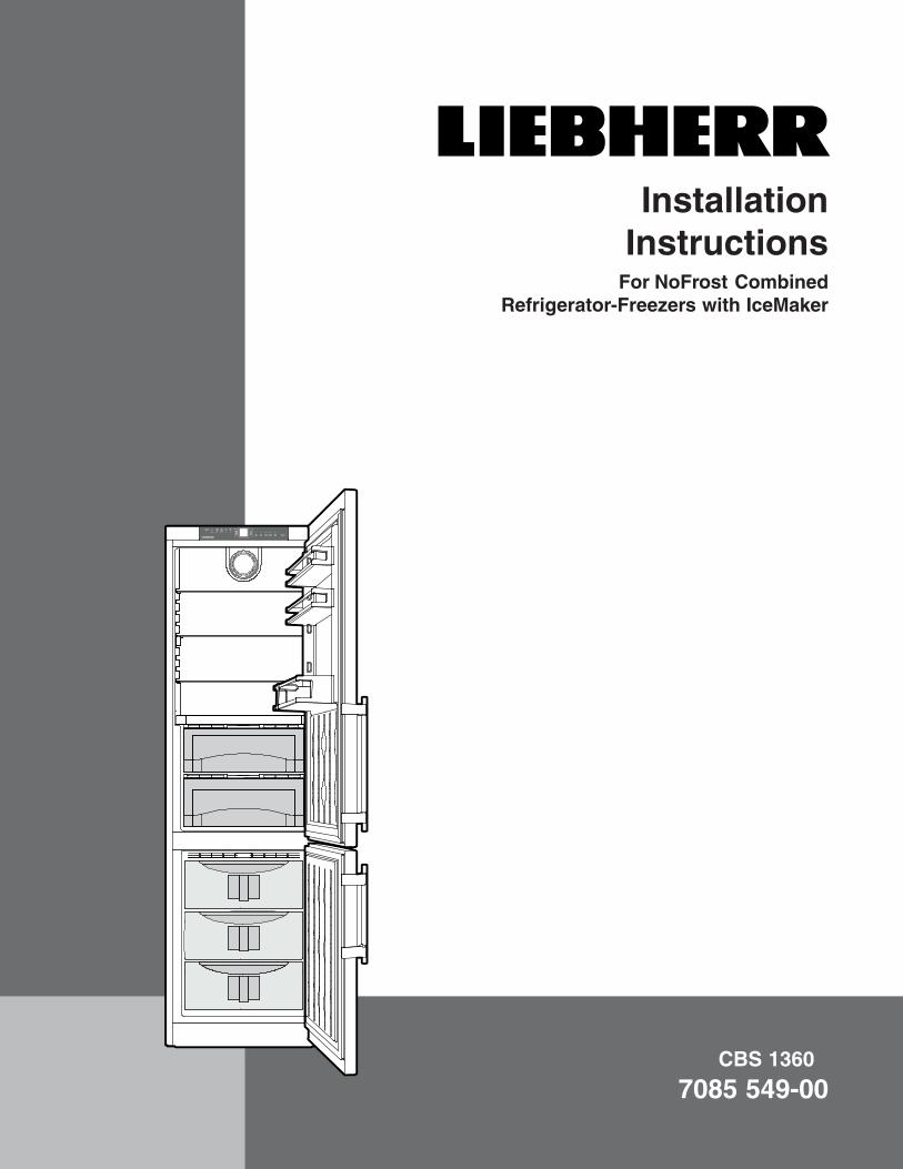
CBS 1360 7085 549-00 Installation Instructions For NoFrost Combined Refrigerator-Freezers with IceMaker
Transcript of 7085 549-00 CBS 13 Install BEREITSTELLEN
CBS 1360
7085 549-00
Installation Instructions
For NoFrost Combined Refrigerator-Freezers with IceMaker
2
Important
Content PagePlease Read and Follow these Instructions.................. 2
Note to the Installer ........................................................ 2
R600a Refrigerant ......................................................... 2
Disposal of Old Appliance ............................................. 3
Disposal of Carton ......................................................... 3
Electrical Safety ............................................................. 3
Blocking for Safety ......................................................... 3
Appliance Dimensions ................................................... 4
Cabinet Opening Dimensions ....................................... 5
Unit Venting .................................................................... 6
Leveling the Appliance .................................................. 6
Mounting the anti tipping device ................................... 7
Safety Instructions and Warnings .................................. 8
Water Connection Requirements .................................. 8
Water Connection Adapter ............................................ 8
Connection to the Water Supply ................................... 9
Changing Over Door Hinges ........................................10
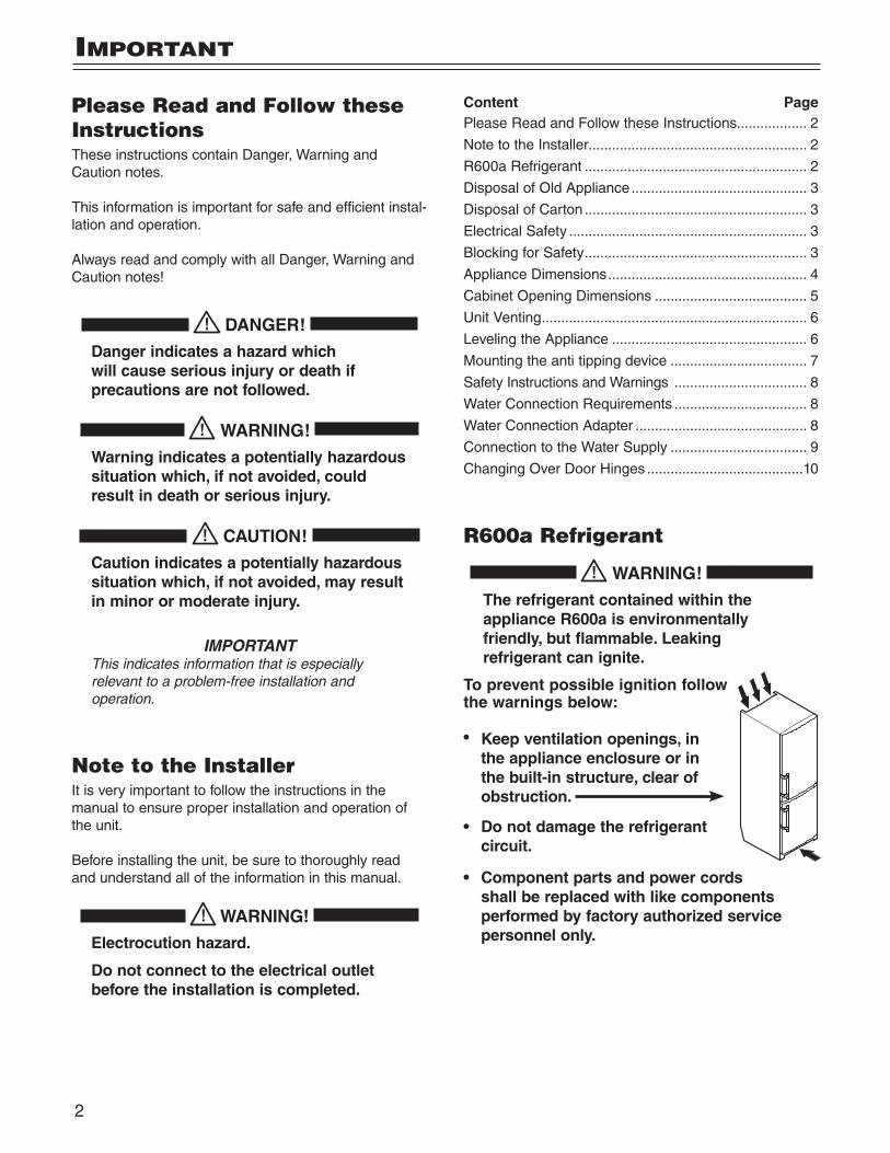
R600a Refrigerant
WARNING!
The refrigerant contained within the appliance R600a is environmentally friendly, but flammable. Leaking refrigerant can ignite.
To prevent possible ignition follow the warnings below:
• Keep ventilation openings, in the appliance enclosure or in the built-in structure, clear of obstruction.
• Do not damage the refrigerant circuit.
• Component parts and power cords shall be replaced with like components performed by factory authorized service personnel only.
Please Read and Follow these InstructionsThese instructions contain Danger, Warning and Caution notes.
This information is important for safe and efficient instal-lation and operation.
Always read and comply with all Danger, Warning and Caution notes!
DANGER!
Danger indicates a hazard which will cause serious injury or death if precautions are not followed.
WARNING!
Warning indicates a potentially hazardous situation which, if not avoided, could result in death or serious injury.
CAUTION!
Caution indicates a potentially hazardous situation which, if not avoided, may result in minor or moderate injury.
IMPORTANTThis indicates information that is especially relevant to a problem-free installation and operation.
Note to the InstallerIt is very important to follow the instructions in the manual to ensure proper installation and operation of the unit.
Before installing the unit, be sure to thoroughly read and understand all of the information in this manual.
WARNING!
Electrocution hazard.
Do not connect to the electrical outlet before the installation is completed.
3
Safety
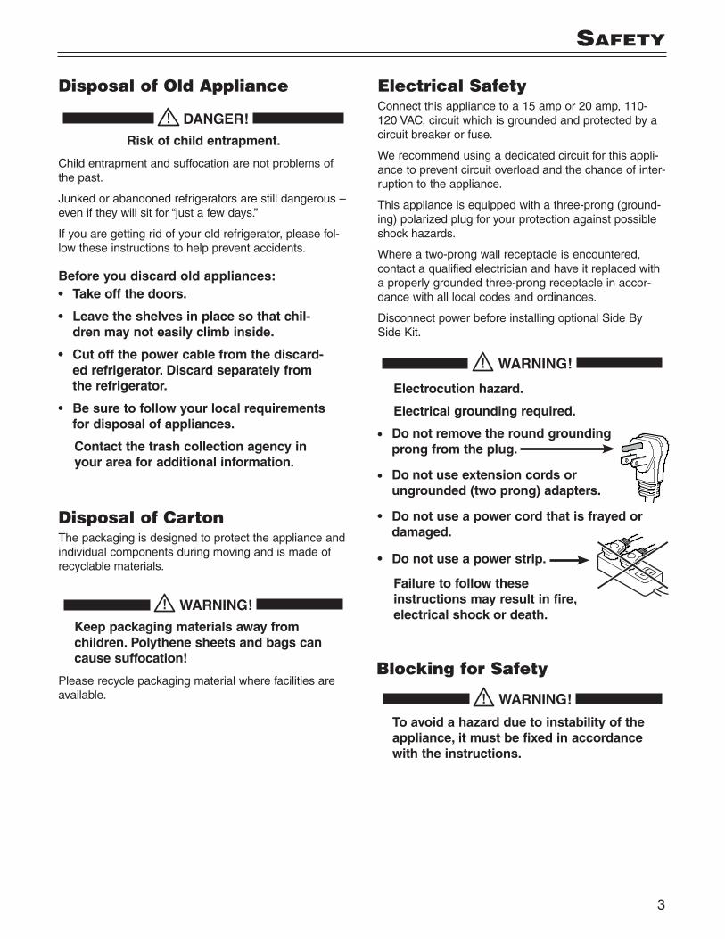
Disposal of Old Appliance
DANGER!
Risk of child entrapment.
Child entrapment and suffocation are not problems of the past.
Junked or abandoned refrigerators are still dangerous – even if they will sit for “just a few days.”
If you are getting rid of your old refrigerator, please fol-low these instructions to help prevent accidents.
Before you discard old appliances:• Take off the doors.
• Leave the shelves in place so that chil-dren may not easily climb inside.
• Cut off the power cable from the discard-ed refrigerator. Discard separately from the refrigerator.
• Be sure to follow your local requirements for disposal of appliances.
Contact the trash collection agency in your area for additional information.
Blocking for Safety
WARNING!
To avoid a hazard due to instability of the appliance, it must be fixed in accordance with the instructions.
Disposal of CartonThe packaging is designed to protect the appliance and individual components during moving and is made of recyclable materials.
WARNING!
Keep packaging materials away from children. Polythene sheets and bags can cause suffocation!
Please recycle packaging material where facilities are available.
Electrical SafetyConnect this appliance to a 15 amp or 20 amp, 110-120 VAC, circuit which is grounded and protected by a circuit breaker or fuse.
We recommend using a dedicated circuit for this appli-ance to prevent circuit overload and the chance of inter-ruption to the appliance.
This appliance is equipped with a three-prong (ground-ing) polarized plug for your protection against possible shock hazards.
Where a two-prong wall receptacle is encountered, contact a qualified electrician and have it replaced with a properly grounded three-prong receptacle in accor-dance with all local codes and ordinances.
Disconnect power before installing optional Side By Side Kit.
WARNING!
Electrocution hazard.
Electrical grounding required.
• Do not remove the round grounding prong from the plug.
• Do not use extension cords or ungrounded (two prong) adapters.
• Do not use a power cord that is frayed or damaged.
• Do not use a power strip.
Failure to follow these instructions may result in fire, electrical shock or death.
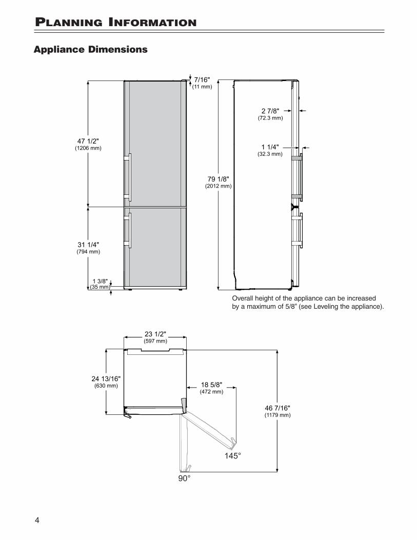
Appliance Dimensions
4
plannIng InformatIon
Overall height of the appliance can be increased by a maximum of 5/8” (see Leveling the appliance).
5
plannIng InformatIon
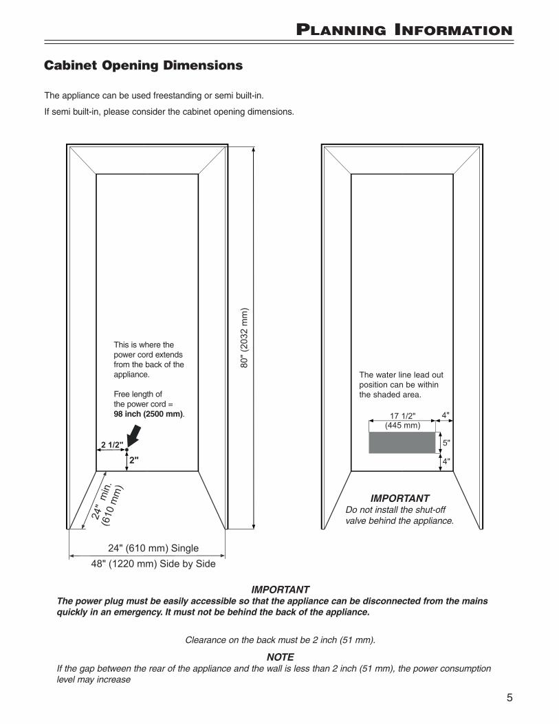
The appliance can be used freestanding or semi built-in.
If semi built-in, please consider the cabinet opening dimensions.
Cabinet Opening Dimensions
This is where the power cord extends from the back of the appliance. Free length of the power cord = 98 inch (2500 mm).
IMPORTANTThe power plug must be easily accessible so that the appliance can be disconnected from the mains quickly in an emergency. It must not be behind the back of the appliance.
IMPORTANTDo not install the shut-off valve behind the appliance.
The water line lead out position can be within the shaded area.
Clearance on the back must be 2 inch (51 mm).
NOTEIf the gap between the rear of the appliance and the wall is less than 2 inch (51 mm), the power consumption level may increase
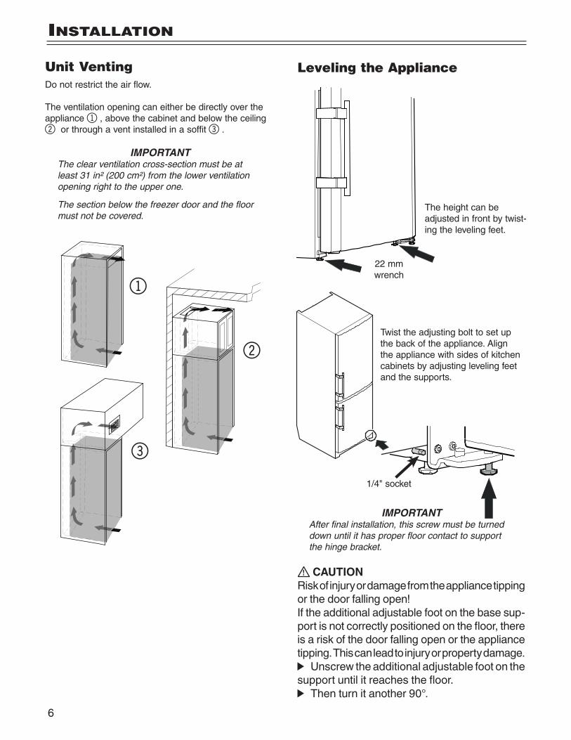
Unit VentingDo not restrict the air flow.
The ventilation opening can either be directly over the appliance 1, above the cabinet and below the ceiling 2 or through a vent installed in a soffit 3.
IMPORTANTThe clear ventilation cross-section must be at least 31 in² (200 cm²) from the lower ventilation opening right to the upper one.
The section below the freezer door and the floor must not be covered.
6
InStallatIon
1/4" socket
22 mm wrench
IMPORTANTAfter final installation, this screw must be turned down until it has proper floor contact to support the hinge bracket.
Leveling the Appliance
The height can be adjusted in front by twist-ing the leveling feet.
Twist the adjusting bolt to set up the back of the appliance. Align the appliance with sides of kitchen cabinets by adjusting leveling feet and the supports.
CAUTIONRisk of injury or damage from the appliance tipping or the door falling open!If the additional adjustable foot on the base sup-port is not correctly positioned on the floor, there is a risk of the door falling open or the appliance tipping. This can lead to injury or property damage.
Unscrew the additional adjustable foot on the support until it reaches the floor.
Then turn it another 90°.
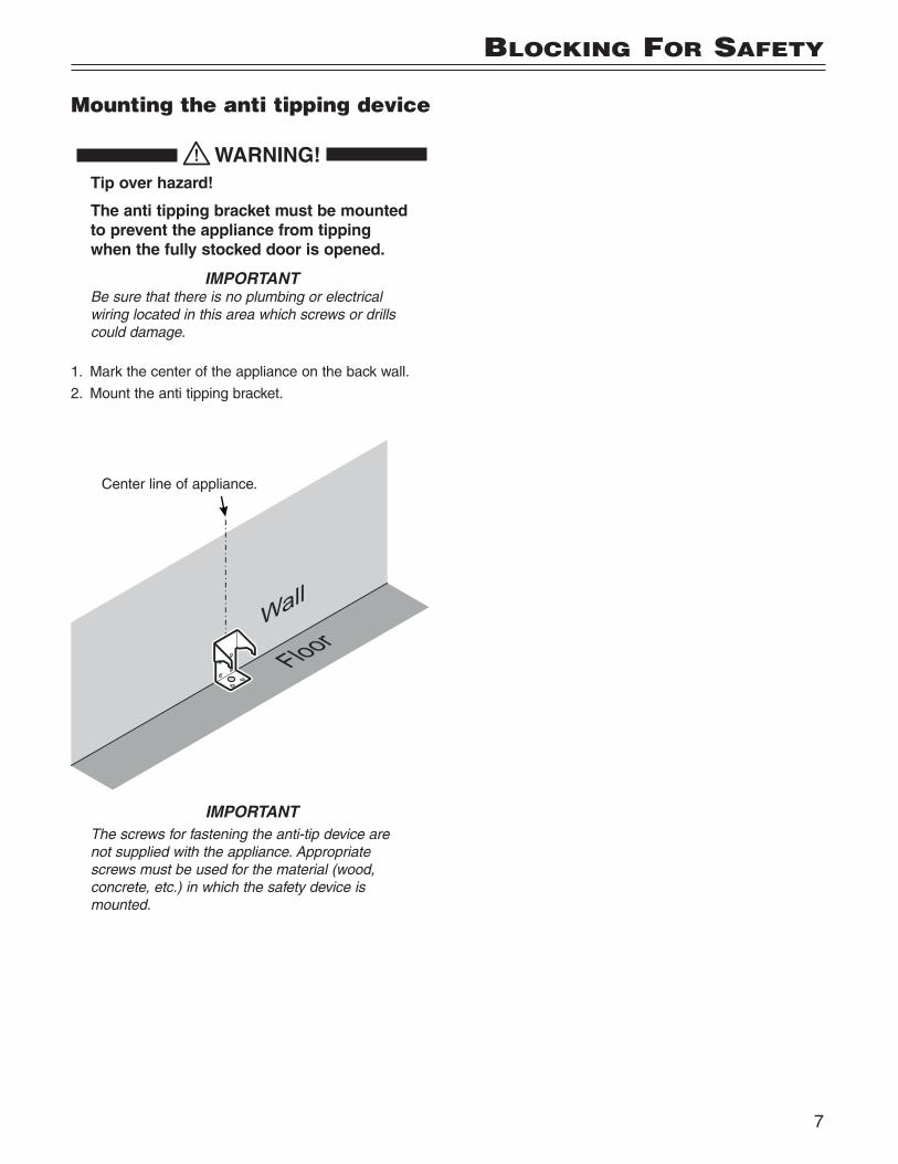
Mounting the anti tipping device
WARNING! Tip over hazard!
The anti tipping bracket must be mounted to prevent the appliance from tipping when the fully stocked door is opened.
IMPORTANTBe sure that there is no plumbing or electrical wiring located in this area which screws or drills could damage.
1. Mark the center of the appliance on the back wall.
2. Mount the anti tipping bracket.
7
BlockIng for Safety
Center line of appliance.
IMPORTANTThe screws for fastening the anti-tip device are not supplied with the appliance. Appropriate screws must be used for the material (wood, concrete, etc.) in which the safety device is mounted.
8
Safety Instructions and Warnings • Do not install the water connection while the com-
bined refrigerator-freezer is connected to an electri-cal outlet.
• The connection to the water supply may only be made by a trained and licensed plumber.
• All equipment and devices used to supply the water to the appliance must comply with the current regula-tions for your geographical area.
WARNING!
Connect to potable water supply only.
Water Connection Requirements• The water supply pressure requirements are different
based on whether or not the supplied Liebherr water filter is installed.
With the filter installed, the pressure must be in the range of 40-90 psi (2.8-6.2 bar).
Without the filter installed, the acceptable pressure range is 22-87 psi (1.5-6 bar).
Failure to meet these requirements will likely result in ice maker malfunction and possibly cause a water leakage that can damage flooring and surrounding furniture.
• A shut-off valve, must be installed between the hose line and the main water supply so the water supply can be stopped if necessary.
IMPORTANTDo not install the shut-off valve behind the appliance.
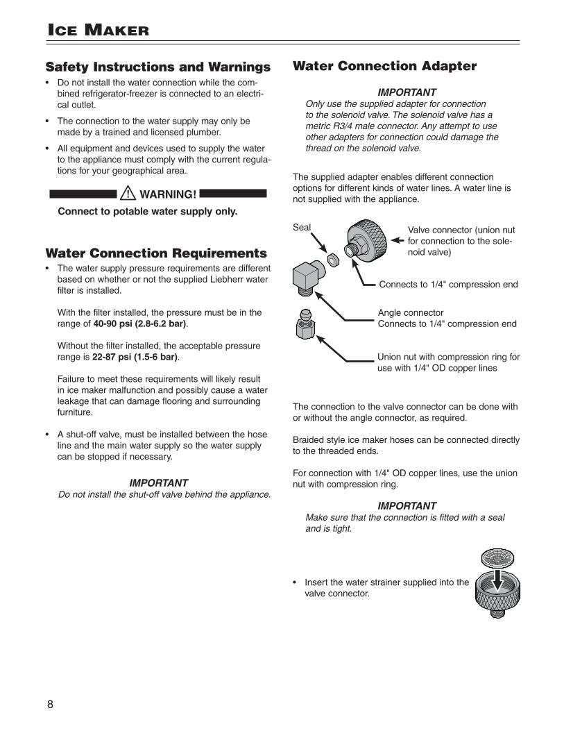
Water Connection Adapter
IMPORTANTOnly use the supplied adapter for connection to the solenoid valve. The solenoid valve has a metric R3/4 male connector. Any attempt to use other adapters for connection could damage the thread on the solenoid valve.
The supplied adapter enables different connection options for different kinds of water lines. A water line is not supplied with the appliance.
Valve connector (union nut for connection to the sole-noid valve)
Connects to 1/4" compression end
Seal
Angle connectorConnects to 1/4" compression end
Union nut with compression ring for use with 1/4" OD copper lines
The connection to the valve connector can be done with or without the angle connector, as required.
Braided style ice maker hoses can be connected directly to the threaded ends.
For connection with 1/4" OD copper lines, use the union nut with compression ring.
IMPORTANTMake sure that the connection is fitted with a seal and is tight.
• Insert the water strainer supplied into the valve connector.
Ice maker
9
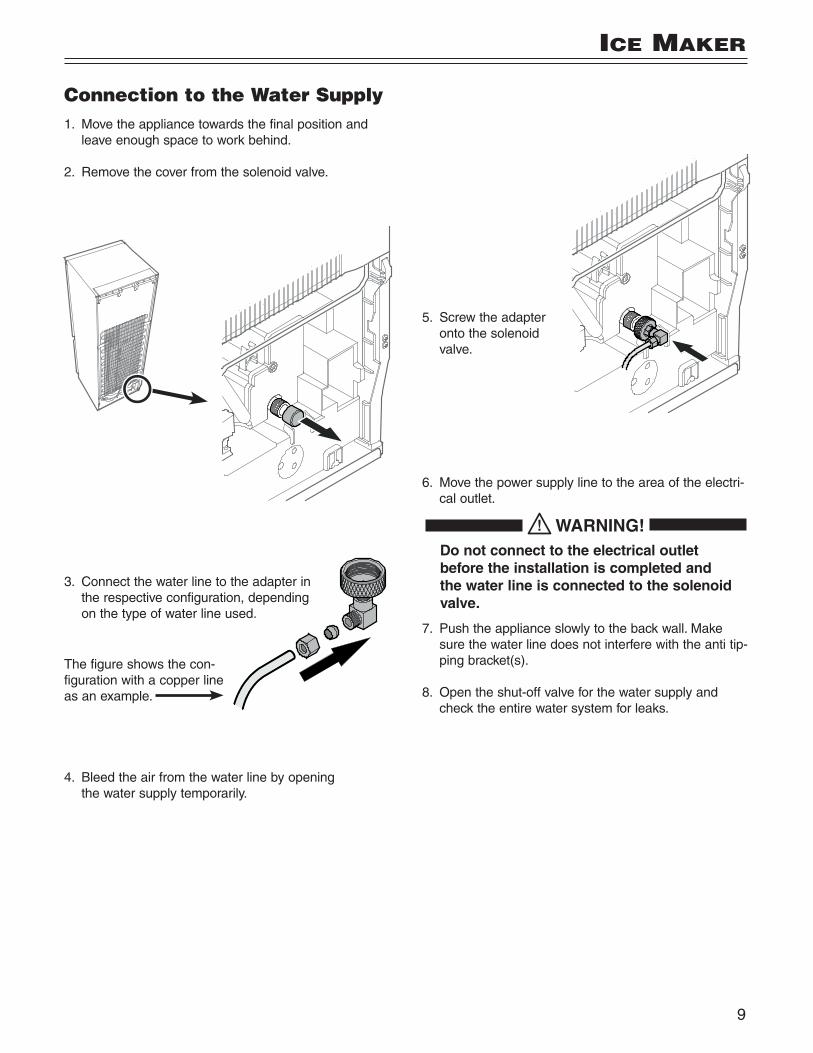
Connection to the Water Supply1. Move the appliance towards the final position and
leave enough space to work behind.
2. Remove the cover from the solenoid valve.
3. Connect the water line to the adapter in the respective configuration, depending on the type of water line used.
4. Bleed the air from the water line by opening the water supply temporarily.
5. Screw the adapter onto the solenoid valve.
6. Move the power supply line to the area of the electri-cal outlet.
WARNING! Do not connect to the electrical outlet before the installation is completed and the water line is connected to the solenoid valve.
7. Push the appliance slowly to the back wall. Make sure the water line does not interfere with the anti tip-ping bracket(s).
8. Open the shut-off valve for the water supply and check the entire water system for leaks.
Ice maker
The figure shows the con-figuration with a copper line as an example.
10
reverSIng Door HIngeS
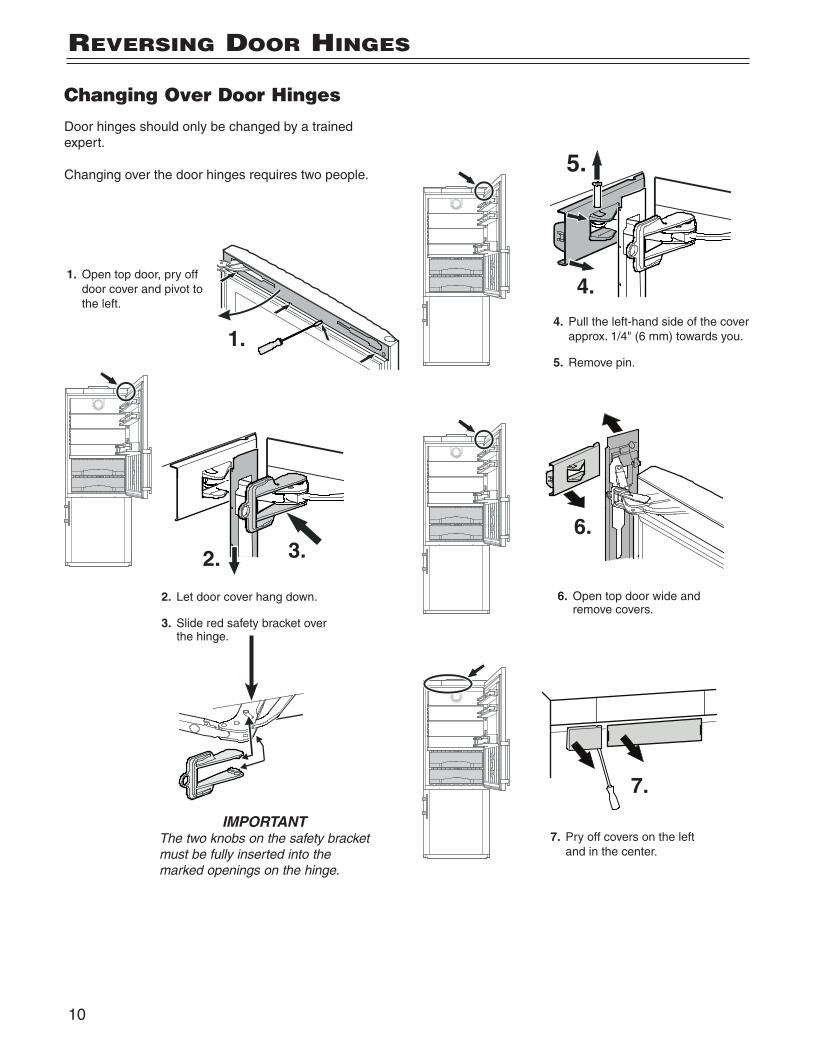
Changing Over Door Hinges
Door hinges should only be changed by a trained expert.
Changing over the door hinges requires two people.
1.
1. Open top door, pry off door cover and pivot to the left.
2. Let door cover hang down.
3. Slide red safety bracket over the hinge.
2. 3.
IMPORTANTThe two knobs on the safety bracket must be fully inserted into the marked openings on the hinge.
4.
5.
6.
6. Open top door wide and remove covers.
4. Pull the left-hand side of the cover approx. 1/4" (6 mm) towards you.
5. Remove pin.
7.
7. Pry off covers on the left and in the center.
11
reverSIng Door HIngeS
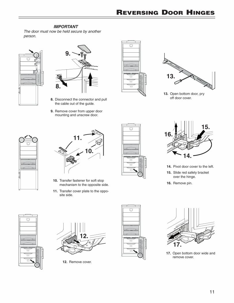
IMPORTANTThe door must now be held secure by another person.
8.
9.
8. Disconnect the connector and pull the cable out of the guide.
9. Remove cover from upper door mounting and unscrew door.
10. Transfer fastener for soft stop mechanism to the opposite side.
11. Transfer cover plate to the oppo-site side.
10.
11.
12.
12. Remove cover.
13.
13. Open bottom door, pry off door cover.
14.
15.16.
14. Pivot door cover to the left.
15. Slide red safety bracket over the hinge.
16. Remove pin.
17.17. Open bottom door wide and
remove cover.
12
reverSIng Door HIngeS
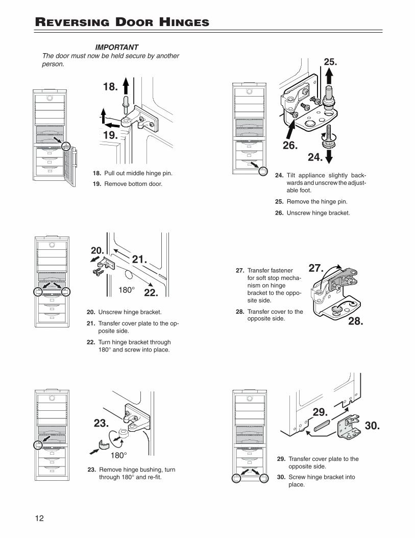
IMPORTANTThe door must now be held secure by another person.
24. Tilt appliance slightly back-wards and unscrew the adjust-able foot.
25. Remove the hinge pin.
26. Unscrew hinge bracket.
27. Transfer fastener for soft stop mecha-nism on hinge bracket to the oppo-site side.
28. Transfer cover to the opposite side.
24.
25.
26.
27.
28.
29. Transfer cover plate to the opposite side.
30. Screw hinge bracket into place.
30.29.
23. Remove hinge bushing, turn through 180° and re-fit.
18. Pull out middle hinge pin.
19. Remove bottom door.
20. Unscrew hinge bracket.
21. Transfer cover plate to the op-posite side.
22. Turn hinge bracket through 180° and screw into place.
18.
19.
20.21.
22.180°
23.
180°
13
32.
33.
33.
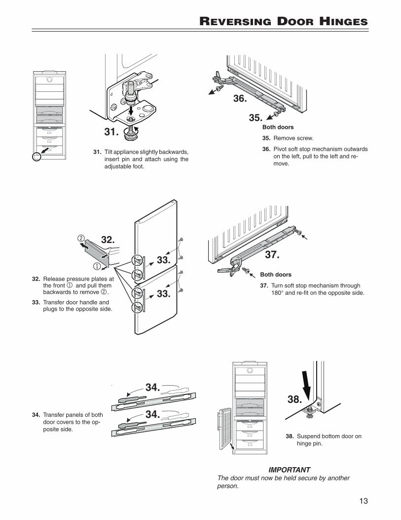
IMPORTANTThe door must now be held secure by another person.
32. Release pressure plates at the front 1 and pull them backwards to remove 2.
33. Transfer door handle and plugs to the opposite side.
31. Tilt appliance slightly backwards, insert pin and attach using the adjustable foot.
34. Transfer panels of both door covers to the op-posite side.
31.
34.
34.
reverSIng Door HIngeS
Both doors
35. Remove screw.
36. Pivot soft stop mechanism outwards on the left, pull to the left and re-move.
Both doors
37. Turn soft stop mechanism through 180° and re-fit on the opposite side.
38. Suspend bottom door on hinge pin.
38.
37.
35.
36.
14
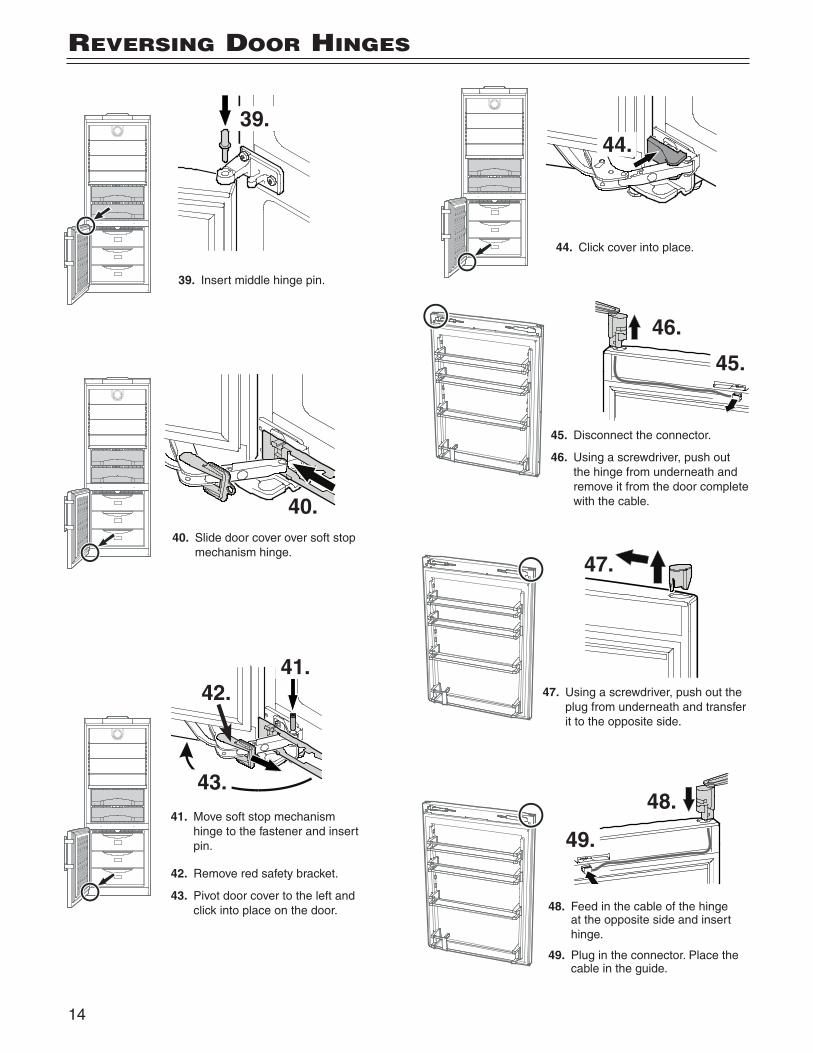
41. Move soft stop mechanism hinge to the fastener and insert pin.
42. Remove red safety bracket.
43. Pivot door cover to the left and click into place on the door.
41.42.
43.
39. Insert middle hinge pin.
40. Slide door cover over soft stop mechanism hinge.
39.
40.
48. Feed in the cable of the hinge at the opposite side and insert hinge.
49. Plug in the connector. Place the cable in the guide.
48.
49.
45. Disconnect the connector.
46. Using a screwdriver, push out the hinge from underneath and remove it from the door complete with the cable.
47. Using a screwdriver, push out the plug from underneath and transfer it to the opposite side.
44. Click cover into place.
44.
45.
46.
47.
reverSIng Door HIngeS
15
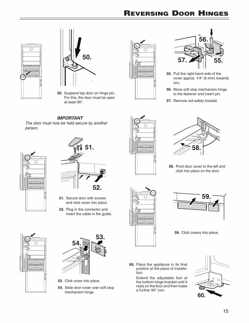
IMPORTANTThe door must now be held secure by another person.
50. Suspend top door on hinge pin. For this, the door must be open at least 90°.
50.
51. Secure door with screws and click cover into place.
52. Plug in the connector and insert the cable in the guide.
53. Click cover into place.
54. Slide door cover over soft stop mechanism hinge.
51.
52.
53.54.
55. Pull the right-hand side of the cover approx. 1/4" (6 mm) towards you.
56. Move soft stop mechanism hinge to the fastener and insert pin.
57. Remove red safety bracket.
58. Pivot door cover to the left and click into place on the door.
59. Click covers into place.
60. Place the appliance in its final position at the place of installa-tion.
Extend the adjustable foot at the bottom hinge bracket until it rests on the floor and then make a further 90° turn.
56.
55.57.
58.
59.
60.
reverSIng Door HIngeS
For Service in the U.S.
Liebherr Service Center
Toll Free: 1-866-LIEBHER or 1-866-543-2437
Email: [email protected]
PlusOne Solutions, Inc. 3501 Quadrangle Blvd, Suite 120Orlando, FL 32817
For Service in Canada
Liebherr Service Center
Toll Free: 1-888-LIEBHER or 1-888-543-2437
www.euro-parts.ca
EURO-PARTS CANADA39822 Belgrave RoadBelgrave, Ontario, N0G 1E0Phone: (519) 357-3320Fax: (519) 357-1326
www. l iebher r-app l iances .com
*708554900*