
70412.201~20 A1 0 ECOTEL-GSM3-1 Manual en - norcom … · VIERLING Page 2 70412.201/20 - 1.0 –...
50
ECOTEL ® GSM3-1 Connecting Telephones, Faxes and PBXs to GSM Networks Operating Instructions Edition 1.0 VIERLING Communications GmbH 70412.201/20 - 1.0 – 20040405
Transcript of 70412.201~20 A1 0 ECOTEL-GSM3-1 Manual en - norcom … · VIERLING Page 2 70412.201/20 - 1.0 –...
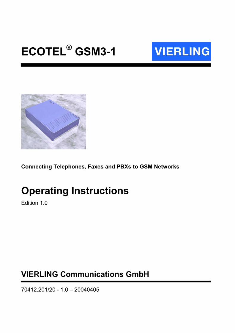
ECOTEL® GSM3-1
Connecting Telephones, Faxes and PBXs to GSM Networks
Operating Instructions Edition 1.0
VIERLING Communications GmbH
70412.201/20 - 1.0 – 20040405
VIERLING
Page 2 70412.201/20 - 1.0 – 20040405 – ECOTEL® GSM3-1
VIERLING Communications GmbH Pretzfelder Strasse 21, D-91320 Ebermannstadt Postbox 11 65, D-91316 Ebermannstadt E-Mail: [email protected] Internet: http://www.vierling.de © 2004 VIERLING Communications GmbH, Ebermannstadt All rights reserved. Any dissemination, reproduction or processing of this document or its contents or excerpts from it, regardless of the procedure used, is prohibited without prior written permission of VIERLING Communications GmbH. We reserve the right to make changes without prior notice. Although this text was conscientiously prepared, VIERLING Communications GmbH assumes no liability should it nevertheless contain errors.
VIERLING
ECOTEL® GSM - 70412.201/20 - 1.0 – 20040405 Page 3
Table of Contents 1. SAFETY INFORMATION ...........................................................7
2. INTRODUCTION ......................................................................10
2.1 Notice .......................................................................................10
2.2 General Comments .................................................................10
2.3 Overview of Device Models....................................................11
3. CONNECTIONS AND DISPLAYS ...........................................13
3.1 Connections ............................................................................13
3.2 Displays ...................................................................................14 3.2.1 Basic Display....................................................................14 3.2.2 Extended Display.............................................................15
4. STARTING OPERATIONS.......................................................16
4.1 Product Package Contents ....................................................16
4.2 Required Accessories ............................................................16
4.3 Installation ...............................................................................16 4.3.1 ECOTEL Location ............................................................17 4.3.2 GSM Antenna Location ...................................................17 4.3.3 Using SIM Cards ..............................................................17 4.3.4 Making Connections........................................................18 4.3.5 Installing the Configuration Program ............................19 4.3.6 Creating Configurations .................................................19
4.3.6.1 Register Cards.................................................................... 19 4.3.6.2 Saving and Transmitting Configurations .................... 20
4.3.7 Activating ECOTEL®GSM .................................................20
VIERLING
Page 4 70412.201/20 - 1.0 – 20040405 – ECOTEL® GSM3-1
4.3.8 Final Control .................................................................... 21
5. HOOK-UP EXAMPLES............................................................ 22
5.1 General Comments................................................................. 22 5.1.1 ECOTEL LCR.................................................................... 23 5.1.2 Manual LCR ...................................................................... 23 5.1.3 PBX LCR ........................................................................... 23 5.1.4 Transferring Calls to Extension Phone Numbers ........ 23
5.2 Without Fixed Network Connections.................................... 25 5.2.1 Without PBXs ................................................................... 25
5.2.1.1 Telephone, Telephone ...................................................... 25 5.2.1.2 Multi-Functional Devices ................................................. 29
5.2.2 With PBXs ........................................................................ 31
5.3 With Fixed Network Connections ......................................... 33 5.3.1 Without PBXs ................................................................... 33 5.3.2 With PBX .......................................................................... 35
5.3.2.1 Manual LCR ......................................................................... 35 5.3.2.2 ECOTEL® LCR..................................................................... 37 5.3.2.3 PBX LCR............................................................................... 39
6. OPERATIONS .......................................................................... 41
6.1 Configuring ECOTEL®GSM ..................................................... 41 6.1.1 Local Configuration......................................................... 41 6.1.2 Remote Configuration..................................................... 41
6.2 Outgoing Calls ........................................................................ 41
6.3 Incoming calls......................................................................... 42 6.3.1 Incoming calls from Mobile Networks........................... 42
7. SERIAL INTERFACE RS-232.................................................. 44
7.1 Configuring ECOTEL.............................................................. 44

VIERLING
ECOTEL® GSM - 70412.201/20 - 1.0 – 20040405 Page 5
7.2 Sending and Receiving SMSs................................................44
7.3 Sending and Receiving Faxes with PCs...............................44 7.3.1 Sending Faxes .................................................................45 7.3.2 Receiving Faxes...............................................................45
7.4 Internet Access .......................................................................45
8. TECHNICAL DATA ..................................................................46
8.1 General Specifications ...........................................................46
8.2 Connection Assignments.......................................................47
9. INDEX OF ABBREVIATIONS ..................................................48

VIERLING
ECOTEL® GSM - 70412.201/20 - 1.0 – 20040405 Page 7
1. Safety Information
General ECOTEL®GSM has been constructed and tested in accordance with EN 60950-1:2001 VDE 0805 part 1: 2003 "Safety of Information-Technology Equipment" and has left the factory in a flawless condition with regard to safety standards. In order to maintain this condition and to ensure operational integrity, the user must observe the information and warnings that are contained in these operating instructions. Maintenance work and repairs on a open device may only be carried out by a qualified technician.
Liability Liability is expressly precluded for damages resulting from the non-observance of safety information provided here. Preclusion of liability does not occur, for example, when life, body or health has been injured, or when a warranty or procurement risks have been assumed, or due to the violation of essential contractual obligations or due to mandatory liability in connection with product liability laws, or other mandatory liability. However, compensation for violation of essential contractual obligations is limited to contract-typical damages that can be anticipated, unless liability should exist for intent or for the fact of gross negligence on the part of our legal representatives or vicarious agents, or for damage to life, body or health, or for the assumption of a warranty or procurement risks. A change of burden of proof to the disadvantage of the user is not connected to the above regulations.
Transport As protection against jolts and impact, ECOTEL®GSM should be transported in its original packing only. Condensation can occur if this device is brought into a room from a cold environment. Before being put into operation, it must be absolutely dry. An acclimation period of at least 2 hours should be observed.
VIERLING
Page 8 70412.201/20 - 1.0 – 20040405 – ECOTEL® GSM3-1
Set-Up Protect this device from direct sunlight and heat. ECOTEL®GSM may only be connected to the mains power by means of the supplied mains power adapter or an original replacement part. Because the plug in power unit and serves as insulation (decollators) from the mains supply circuit, the terminal equipment itself should be installed in such a way that the power outlet will be close at hand and easily accusable.
Connecting Cables Lay the cables in a manner that is not hazardous to pedestrian traffic. For units installed indoors: To completely disconnect the power, e.g. in emergencies, the power cord must be unplugged from the mains socket. Cables should not be connected nor disconnected during thunderstorms!
Antenna Input Measures that afford protection against lighting and electrical storms must be taken before using an external antenna. In particular, the antenna base must be grounded.
Damage For safety reasons, if the device shows visible damage, or has been exposed to moisture, further operation should be avoided! In such a case, insure that ECOTEL®GSM can no longer be operated by other persons.
Environmental Conditions ECOTEL®GSM may only be used in compliance with the environmental conditions specified. Make sure that no foreign matter can arrive into the device opening, such as dust, dirt or liquid.
VIERLING
ECOTEL® GSM - 70412.201/20 - 1.0 – 20040405 Page 9
Repairs Repairs may only be carried out by qualified technicians. Only use replacement parts that comply with the unit's safety standards. Always unplug the mains connector before opening the device!
Expansions Only install system expansions that are intended for ECOTEL®GSM. Installing other expansions can damage the system or violate safety standards and radio interference suppression regulations.
Cleaning Before cleaning, pull the power supply plug. The housing interior may only be cleaned by an authorized technician. Do not use scouring powder or solvents harmful to plastics. Do not allow liquids to penetrate into the interior of the device. A dry cloth suffices for cleaning the housing-surface. A cloth dipped in water containing a mild detergent and then wrung out well can be used for heavier stains.

VIERLING
Page 10 70412.201/20 - 1.0 – 20040405 – ECOTEL® GSM3-1
2. Introduction
2.1 Notice
This device is approved in accord with EG Directive 98/482/EC for use in Europe in public telephone networks. Due to technical differences in GSM networks and in analog fax devices, however, this existing certification should not be viewed as assuring that analog fax functions can be generally utilized without possible limitations. GSM networks should provide fax data rates of 4800 bps for analog fax functions. In Germany, this prerequisite is currently fulfilled in GSM networks by D1, D2 and e-plus.
2.2 General Comments
For many companies, telephone and mobile phone charges have become significant cost factors. High costs are generated in particular by connections made between fixed networks and mobile phone networks. ECOTEL®GSM provides a bridge from analog fixed-network terminal devices to GSM mobile networks. Thus, when using ECOTEL®GSM, favorable internal tariffs of mobile networks become available, which result in substantial cost savings. ECOTEL®GSM offers interface connections for the following terminal devices:
• Telephones • Faxes • Multi-functional devices • PBXs (extension side) • PBXs (exchange side) • Fixed Networks (POTS)
Analog devices can be hooked-up with RJ11 connecting cables. ECOTEL®GSM also offers the option of connecting a PC lap-top which permits operation of the following features:
• Easy configuration of the Windows user-interface • PC-Fax function
VIERLING
ECOTEL® GSM - 70412.201/20 - 1.0 – 20040405 Page 11
• PC-SMS function • Data function (Internet access over GSM)
The PC is to be hooked-up over a V.24 (RS-232) interface. ECOTEL®GSM is integrated into a housing that makes it suitable for use as a desktop model or, as an alternative, it may also be mounted on the wall.
2.3 Overview of Device Models
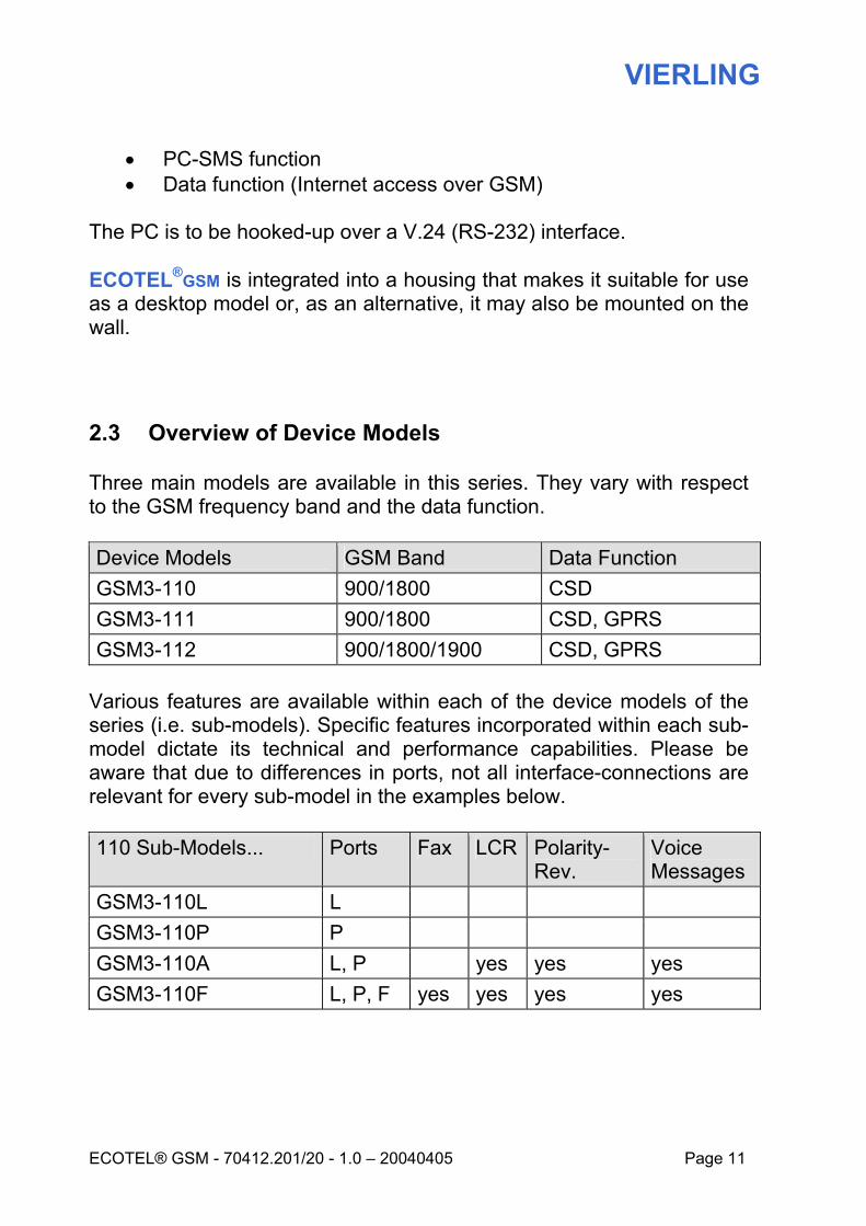
Three main models are available in this series. They vary with respect to the GSM frequency band and the data function. Device Models GSM Band Data Function GSM3-110 900/1800 CSD GSM3-111 900/1800 CSD, GPRS GSM3-112 900/1800/1900 CSD, GPRS
Various features are available within each of the device models of the series (i.e. sub-models). Specific features incorporated within each sub-model dictate its technical and performance capabilities. Please be aware that due to differences in ports, not all interface-connections are relevant for every sub-model in the examples below. 110 Sub-Models... Ports Fax LCR Polarity-
Rev. Voice Messages
GSM3-110L L GSM3-110P P GSM3-110A L, P yes yes yes GSM3-110F L, P, F yes yes yes yes

VIERLING
Page 12 70412.201/20 - 1.0 – 20040405 – ECOTEL® GSM3-1
111 Sub-Models... Ports Fax LCR Polarity-
Rev. Voice Messages
GSM3-111A L, P yes yes yes GSM3-111F L, P, F yes yes yes yes
112 Sub-Models... Ports Fax LCR Polarity-
Rev. Voice Messages
GSM3-112A L, P yes yes yes GSM3-112F L, P, F yes yes yes yes
L=Line, P=Phone, F=Fax, A=Advanced

VIERLING
ECOTEL® GSM - 70412.201/20 - 1.0 – 20040405 Page 13
3. Connections and Displays
3.1 Connections
Illustration 1 depicts the reverse side of the device with its different interface connections. Interface connection availability depends upon the specific device model in question and its optional (sub-model) features.
DC In PhoneLine
Ant
RS-232
SIM
FaxFXSFXO FXS
Illustration 1: Reverse Side of Device Showing Various Interface Connections
Table 1 describes the various device connections.
Connection Description
DC In Power supply (plug-in power supply unit)
FXO Line Telephone network interface (requires power supply)
FXS Phone Telephone connection (furnishes power supply)
FXS Fax Fax interface connection (furnishes power supply)
RS-232 Interface for laptop/PC (Cable not crossed)
SIM Card receptacle for SIM cards
Ant GSM antenna connection Table 1: Description of Device Connections
VIERLING
Page 14 70412.201/20 - 1.0 – 20040405 – ECOTEL® GSM3-1
3.2 Displays
The ECOTEL®GSM housing has 7 light-emitting diodes (LEDs) which are arranged into two groups of 3 and 4 signals respectively. This configuration then functions in either a basic or extended display mode.
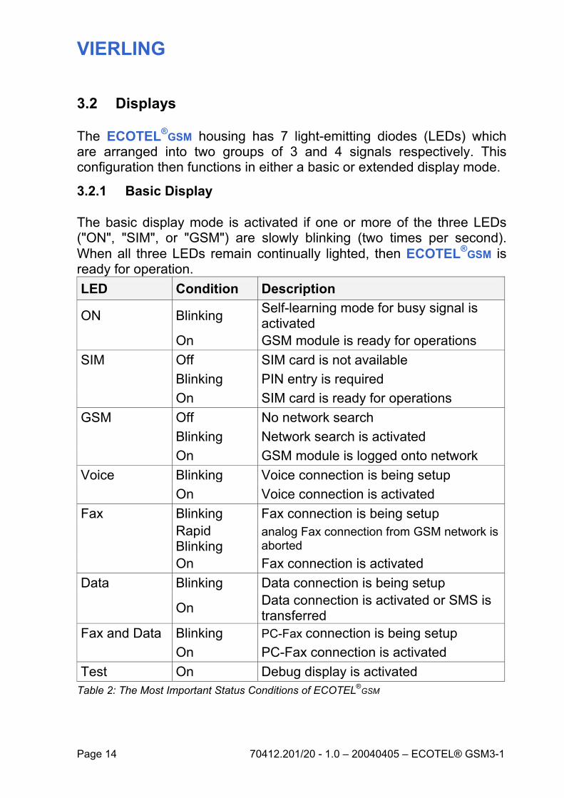
3.2.1 Basic Display
The basic display mode is activated if one or more of the three LEDs ("ON", "SIM", or "GSM") are slowly blinking (two times per second). When all three LEDs remain continually lighted, then ECOTEL®GSM is ready for operation. LED Condition Description
ON Blinking Self-learning mode for busy signal is activated
On GSM module is ready for operations SIM Off SIM card is not available Blinking PIN entry is required On SIM card is ready for operations GSM Off No network search Blinking Network search is activated On GSM module is logged onto network Voice Blinking Voice connection is being setup On Voice connection is activated Fax Blinking Fax connection is being setup
Rapid Blinking
analog Fax connection from GSM network is aborted
On Fax connection is activated Data Blinking Data connection is being setup
On Data connection is activated or SMS is transferred
Fax and Data Blinking PC-Fax connection is being setup On PC-Fax connection is activated Test On Debug display is activated
Table 2: The Most Important Status Conditions of ECOTEL®GSM
VIERLING
ECOTEL® GSM - 70412.201/20 - 1.0 – 20040405 Page 15
All basic display mode functions correspond with their respective LED labels. (SMS is included in "Data" connections in this respect). The most important ECOTEL®GSM status conditions are described in Table 2. During the boot-phase of ECOTEL®GSM, all 7 LEDs remain lighted. In this condition, ECOTEL®GSM is still not ready for operations.
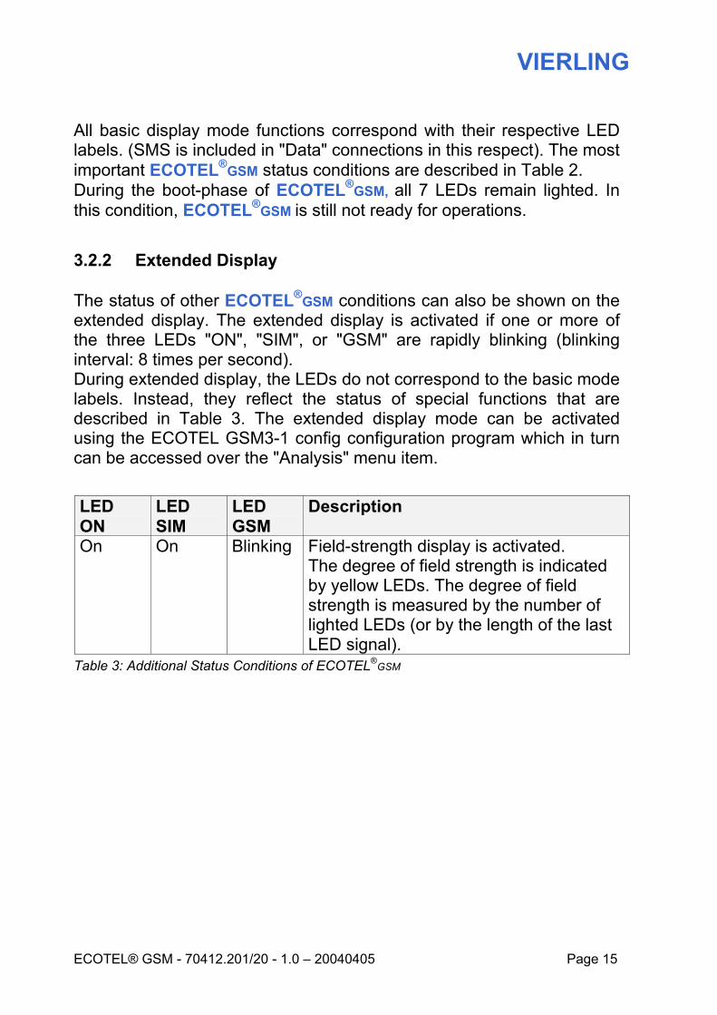
3.2.2 Extended Display
The status of other ECOTEL®GSM conditions can also be shown on the extended display. The extended display is activated if one or more of the three LEDs "ON", "SIM", or "GSM" are rapidly blinking (blinking interval: 8 times per second). During extended display, the LEDs do not correspond to the basic mode labels. Instead, they reflect the status of special functions that are described in Table 3. The extended display mode can be activated using the ECOTEL GSM3-1 config configuration program which in turn can be accessed over the "Analysis" menu item.
LED ON
LED SIM
LED GSM
Description
On On Blinking Field-strength display is activated. The degree of field strength is indicated by yellow LEDs. The degree of field strength is measured by the number of lighted LEDs (or by the length of the last LED signal).
Table 3: Additional Status Conditions of ECOTEL®GSM
VIERLING
Page 16 70412.201/20 - 1.0 – 20040405 – ECOTEL® GSM3-1
4. Starting Operations
4.1 Product Package Contents
Before starting operations, check the product package to assure that all items were included.
• ECOTEL®GSM • Plug-in power supply unit • Connecting cable Line to PBX (RJ11-RJ11) • Connecting cable Phone to PBX (RJ11-RJ11) • Operating Instructions ECOTEL GSM3-1 • CD-ROM ECOTEL GSM3-1 • Antenna connection adapter SMA-FME
4.2 Required Accessories
Operational start-up will require the following accessories which are not included in the product package.
• SIM card (with fax and data telephone number, if necessary) • GSM antenna (GSM900/GSM1800/GSM1900) • PC (lap-top) to configure ECOTEL®GSM • Serial cable, 9-pole D-SUB (connection to PC, cable not
crossed) • Telephone/ Fax/ PBX
4.3 Installation
The installation steps that follow should be carefully implemented as described and in the order presented. This will help to assure trouble-free operations.

VIERLING
ECOTEL® GSM - 70412.201/20 - 1.0 – 20040405 Page 17
4.3.1 ECOTEL Location
Select a suitable location for ECOTEL®GSM. Take into consideration the location of all analog terminal devices that are to be operated over ECOTEL®GSM plus the mains power supply outlet and general environmental conditions.
• Telephone • Fax device • PBX • Fixed network connection (if required) • Power supply (power supply unit)
4.3.2 GSM Antenna Location
A short antenna connected directly to the housing is sufficient if conditions are good for GSM reception (for example VIERLING Mini Antenna, order number 70459.111). Otherwise, an external antenna should be used which is connected using an antenna cable (for example Station Antenna, order number 47560.010). External antennas must be protected against damages that can be caused by lightening. The antenna base must be grounded. In order to estimate GSM reception conditions, the field strength display of a mobile phone can be used prior to installation. After installation, the ECOTEL®GSM LED display offers the possibility of accessing field strength.
4.3.3 Using SIM Cards
Protect your ECOTEL®GSM SIM card by utilizing a PIN. To do this, insert the SIM card into a mobile phone and activate the PIN. Details regarding activating and modifying PINs can be found in your mobile phone operating instructions. Should you decide to leave the SIM card unprotected, the PIN function must be deactivated. Details in this regard are also included in your mobile phone operating instructions.
VIERLING
Page 18 70412.201/20 - 1.0 – 20040405 – ECOTEL® GSM3-1
NOTE:
Some providers do not allow the PIN function of SIM cards to be deactivated.
Now insert the SIM card into ECOTEL®GSM. Proceed as follows:
• Remove the SIM-drawer by pressing the button (e.g. with a ballpoint pen or biro)
• Insert SIM card into the SIM-drawer. Ensure that it is properly seated (not beveled, etc.).
• Re-insert the SIM-drawer until it clicks into the housing. If you wish to receive faxes with ECOTEL®GSM, a SIM card with an additional telephone number for faxes is required. If you wish to receive data with ECOTEL®GSM, a SIM card with an additional telephone number for data is required. Direct any questions you may have in this regard to your provider. Additional telephone numbers are not required in order to only send faxes or to use GSM to access the internet over ECOTEL®GSM.
4.3.4 Making Connections
Select a suitable example from section 5 "Hook-Up Examples" and make the connections from ECOTEL®GSM accordingly. Take into account the following interfaces:
• FXS Phone Connection • FXO Line Connection • FXS Fax Connection • Antenna Connection • RS-232 (for the configuration, for example)

VIERLING
ECOTEL® GSM - 70412.201/20 - 1.0 – 20040405 Page 19
4.3.5 Installing the Configuration Program
Insert the ECOTEL®GSM CD-ROM which is included in the product package and start the setup.exe program (located in the index \Software\ECOTEL-GSM3-config). Follow the installation instructions. After installation is successfully completed, the program can be started over the Start menu: Start – Programs – ECOTEL – ECOTEL GSM3-1 config Additional assistance in operating the ECOTEL GSM3-1 config configuration program can be found in the program's Online help. This can be accessed (context-supported) over F1 or in the Help menu.
4.3.6 Creating Configurations
A configuration should now be created for ECOTEL®GSM in accord with the hook-up example selected and the functions that you require. This is easily done using the Windows program "ECOTEL GSM3-1 config".
• Start the configuration program with Start – Programs – ECOTEL – ECOTEL GSM3-1 config
• Create a new configuration program with File – New
• Select a device model. If you are uncertain, the model specification can be found on the bottom of your ECOTEL®GSM housing.
• The configuration window with register cards is now displayed.
4.3.6.1 Register Cards
Configuration settings can now be made by using the 9 register cards. Depressing F1 in the configuration program accesses a context-supported online help specifically for the register card which is currently opened. Always enter your settings in the "Basic Settings" register card first; and then in the "Mobile Network -> ECOTEL" card. This procedure helps avoid making conflicting entries in the register cards.

VIERLING
Page 20 70412.201/20 - 1.0 – 20040405 – ECOTEL® GSM3-1
The settings for all devices connected to ECOTEL®GSM are contained in the "Basic Settings" register card. Find a suitable hook-up schematic in section 5 "Hook-Up Examples". Enter into the "Basic Settings" register card each device which is coupled to the Phone, Fax and Line connections. Then select the through-switching that is depicted in either picture 1 or picture 2 (ECOTEL-LCR). Section 5 depicts suitable through-switching for all hook-up examples. Settings in the register card labeled "Mobile Network -> ECOTEL" are concerned with all incoming calls from the mobile network to ECOTEL®GSM. Depending upon the hook-up example selected, these calls can be through-switched to the Line or to the Phone/Fax connection. Select the through-switching that is desired for voice calls and for fax calls.
4.3.6.2 Saving and Transmitting Configurations
After all settings have been entered, this file should then be saved to your PC hard disk using "Save File". Transferring this configuration for ECOTEL®GSM is then accomplished using "Transfer – Configuration Download". This procedure requires that ECOTEL®GSM be switched on ; In this regard, ECOTEL®GSM must be switched-on and connected to the PC with a non-crossed serial cable; additionally, the ON LED must be lighted or be blinking. Refer to the following section.
4.3.7 Activating ECOTEL®GSM
Couple the ECOTEL®GSM DC In connection to the power supply unit and plug the unit into the mains socket. ECOTEL®GSM is turned on by the application of current. All seven LEDs immediately light up for about 5 seconds. Then the operating status of ECOTEL is displayed by the respective LEDs. As soon as LED "ON" is lighted or blinking, communication with the configuration program is possible. A description of all LEDs can be found in section 3.2 "Displays".
VIERLING
ECOTEL® GSM - 70412.201/20 - 1.0 – 20040405 Page 21
4.3.8 Final Control
After having transmitted the configuration, ECOTEL®GSM will operate in accord with the settings that were selected. LED ON When blinking, LED "ON" signals that ECOTEL®GSM does not yet recognize the PBX busy signal. If ECOTEL®GSM is connected to the extension of a PBX with the Line connection, then it must be able to recognize the PBX busy signal in order to function properly. In this case, ECOTEL®GSM should be dialed from an extension; after hearing the voice message "Here mobile phone connection," the receiver should be hung up immediately. Then the PBX will, in turn, send a busy signal to the Line connection. This signal will be evaluated by ECOTEL®GSM, and after the busy signal is successfully recognized, LED "ON" will remain lighted.
LED SIM When LED "SIM" is blinking, this signals a problem related to transferring a PIN from ECOTEL®GSM to a SIM card. Review the PIN as well as Activation/Deactivation. Refer to section 4.3.3 "Using SIM Cards" and to the PIN register card in the configuration program. If LED "SIM" does not light up, then a problem exists in connection with SIM cards. LED GSM A blinking LED "GSM" signals that ECOTEL®GSM is executing a GSM network search. If the LED blinks longer than 30 seconds, please review the GSM field strength. GSM Field Strength GSM field strength can be determined with the ECOTEL GSM3-1 config configuration program. Menu: "Transfer – ECOTEL Status - Measurement". Field strength should be within the range of –82 dBm and – 51 dBm.

VIERLING
Page 22 70412.201/20 - 1.0 – 20040405 – ECOTEL® GSM3-1
5. Hook-Up Examples
5.1 General Comments
The following examples of hook-ups are divided into the two categories: Without Fixed Network Connections and With Fixed Network Connections. Both categories are then further differentiated by the attributes Without PBX and With PBX. Not all device models offer the same features and therefore some of the hook-up examples will not apply to some devices. For further information, refer to section 2.3 Overview of Device Models.
Various hook-up options are available for ECOTEL®GSM depending upon the operational requirements in question and the functions desired. As an example, the LCR function can be controlled either by the PBX (PBX-LCR) or by ECOTEL®GSM (ECOTEL-LCR). Furthermore, only certain hook-up examples allow extension suffix-dialing.
Hook-up examples
With fixed network connection Without fixed network connection
Without PBX
ECOTEL-LCR
Without PBX
With PBX With PBX
Manual LCR
ECOTEL LCR
PBX LCR
VIERLING
ECOTEL® GSM - 70412.201/20 - 1.0 – 20040405 Page 23
5.1.1 ECOTEL LCR
The ECOTEL LCR function provides technology to avoid the high tariffs/ high costs of network transition (fixed network/ mobile network) when dialing outgoing calls. Depending upon the telephone number being dialed, the most economic choice is automatically made between fixed and mobile networks.
5.1.2 Manual LCR
The manual LCR function is defined as the manual selection between fixed networks and mobile networks for outgoing calls being made from an extension. If the caller dials the desired telephone number in the usual manner, the call will be routed by the PBX over the exchange connection into the fixed network. On the other hand, if the caller first dials the ECOTEL®GSM extension and then the desired telephone number, the call is routed by ECOTEL®GSM into the mobile network.
5.1.3 PBX LCR
PBXs with two exchange connections are generally able to supply an LCR function. The PBX will route certain telephone numbers/ number-groups to exchange connection 1 and other numbers to exchange connection 2. Further information in this regard can be found in your PBX operating instructions.
5.1.4 Transferring Calls to Extension Phone Numbers
If ECOTEL®GSM is connected to a PBX extension over the Line connection, then several options are available when transferring calls to other extension (telephone) numbers. Be sure to take this possibility into consideration when selecting a suitable hook-up example. Refer to section 6.3 "Incoming calls".
If ECOTEL®GSM is connected to a PBX extension over the Line connection and if direct outward dialing is enabled for that connection, then ECOTEL®GSM also offers the option of suffix-dialing into the public fixed network. However, direct dialing into the public network must also be authorized in the configuration. In such cases, the caller assumes the costs for connections to ECOTEL®GSM and the operator of
VIERLING
Page 24 70412.201/20 - 1.0 – 20040405 – ECOTEL® GSM3-1
ECOTEL®GSM assumes the costs for connections from ECOTEL®GSM into the public fixed network.
VIERLING
ECOTEL® GSM - 70412.201/20 - 1.0 – 20040405 Page 25
5.2 Without Fixed Network Connections
5.2.1 Without PBXs
5.2.1.1 Telephone, Telephone
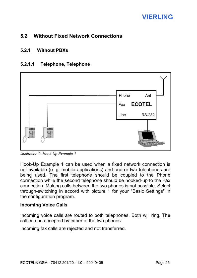
Illustration 2: Hook-Up Example 1
Hook-Up Example 1 can be used when a fixed network connection is not available (e. g. mobile applications) and one or two telephones are being used. The first telephone should be coupled to the Phone connection while the second telephone should be hooked-up to the Fax connection. Making calls between the two phones is not possible. Select through-switching in accord with picture 1 for your "Basic Settings" in the configuration program.
Incoming Voice Calls
Incoming voice calls are routed to both telephones. Both will ring. The call can be accepted by either of the two phones. Incoming fax calls are rejected and not transferred.
ECOTEL
AntPhone
Fax
Line RS-232
VIERLING
Page 26 70412.201/20 - 1.0 – 20040405 – ECOTEL® GSM3-1
Outgoing Voice Calls Outgoing voice calls can be made from either of the two phones. The desired telephone number must first be dialed and then followed by the hatch (#) symbol.
Outgoing Fax Calls Not possible.
Advantages: Incoming calls can be accepted by either of the two telephones. Outgoing calls can be made over either of the two telephones. Transferring the call is possible from the telephone on the phone Line to the telephone on the fax Line or vice-versa. This requires first picking up the receiver on one telephone and then replacing the receiver on the other phone. Listening to the call from both telephones is not permitted and is prevented by ECOTEL GSM.
VIERLING
ECOTEL® GSM - 70412.201/20 - 1.0 – 20040405 Page 27
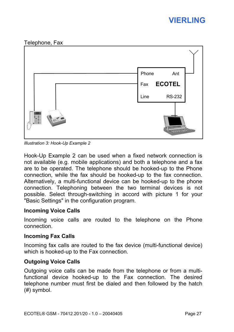
Telephone, Fax
Illustration 3: Hook-Up Example 2
Hook-Up Example 2 can be used when a fixed network connection is not available (e.g. mobile applications) and both a telephone and a fax are to be operated. The telephone should be hooked-up to the Phone connection, while the fax should be hooked-up to the fax connection. Alternatively, a multi-functional device can be hooked-up to the phone connection. Telephoning between the two terminal devices is not possible. Select through-switching in accord with picture 1 for your "Basic Settings" in the configuration program.
Incoming Voice Calls Incoming voice calls are routed to the telephone on the Phone connection.
Incoming Fax Calls Incoming fax calls are routed to the fax device (multi-functional device) which is hooked-up to the Fax connection.
Outgoing Voice Calls Outgoing voice calls can be made from the telephone or from a multi-functional device hooked-up to the Fax connection. The desired telephone number must first be dialed and then followed by the hatch (#) symbol.
ECOTEL
AntPhone
RS-232
Fax
Line
VIERLING
Page 28 70412.201/20 - 1.0 – 20040405 – ECOTEL® GSM3-1
Outgoing Fax Calls Outgoing fax calls can be made from the fax (multi-functional device) that is hooked-up to the Fax connection. The desired fax number must be dialed first, and then followed by the star (*) symbol.
Advantages Incoming fax calls are routed to the Fax connection while incoming voice calls are routed to the Phone connection.
VIERLING
ECOTEL® GSM - 70412.201/20 - 1.0 – 20040405 Page 29
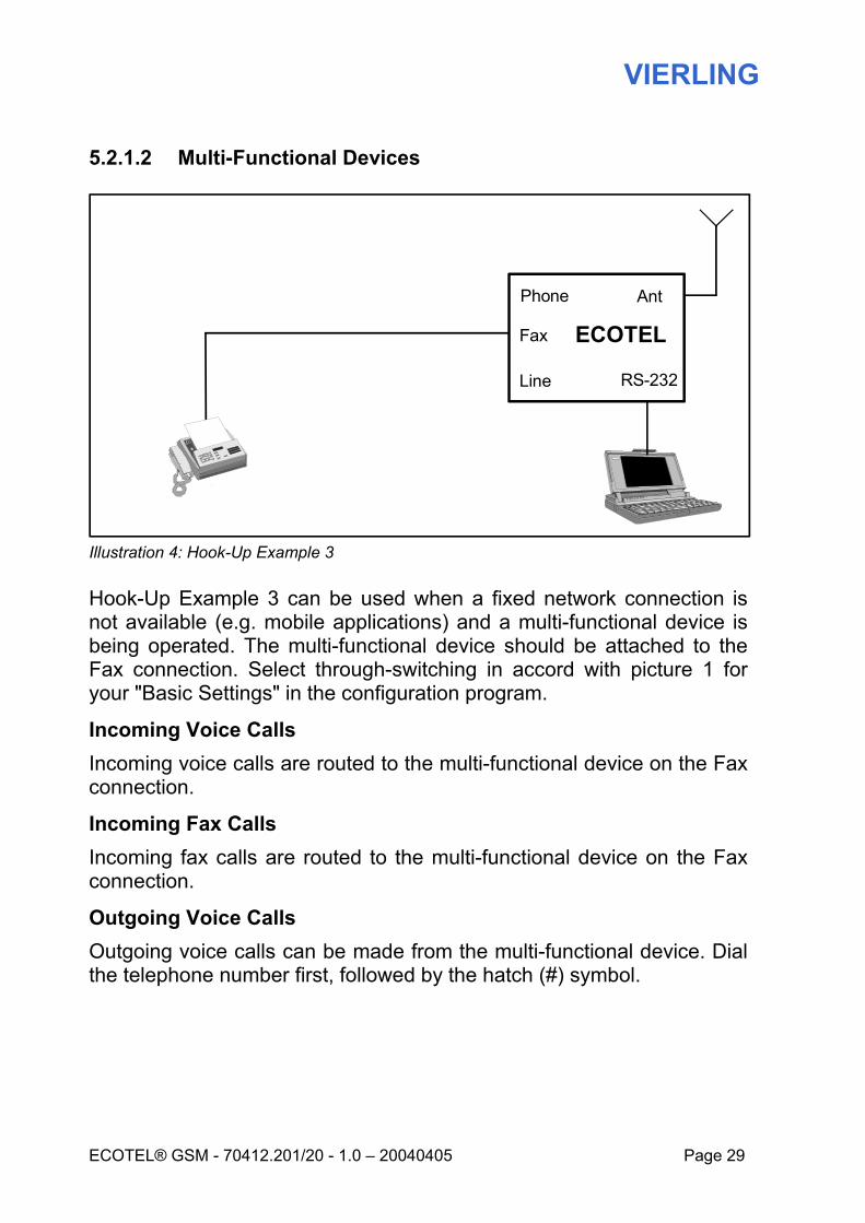
5.2.1.2 Multi-Functional Devices
Illustration 4: Hook-Up Example 3
Hook-Up Example 3 can be used when a fixed network connection is not available (e.g. mobile applications) and a multi-functional device is being operated. The multi-functional device should be attached to the Fax connection. Select through-switching in accord with picture 1 for your "Basic Settings" in the configuration program.
Incoming Voice Calls Incoming voice calls are routed to the multi-functional device on the Fax connection.
Incoming Fax Calls Incoming fax calls are routed to the multi-functional device on the Fax connection.
Outgoing Voice Calls Outgoing voice calls can be made from the multi-functional device. Dial the telephone number first, followed by the hatch (#) symbol.
ECOTEL
AntPhone
Fax
Line RS-232
VIERLING
Page 30 70412.201/20 - 1.0 – 20040405 – ECOTEL® GSM3-1
Outgoing Fax Calls Outgoing fax calls can be made from the multi-functional device. The fax number should be dialed first, followed by the star (*) symbol.
Advantages A multi-functional device can be operated on the Fax connection. Incoming fax and voice calls from the mobile network are through-switched to the Fax connection (multi-functional device).
VIERLING
ECOTEL® GSM - 70412.201/20 - 1.0 – 20040405 Page 31
5.2.2 With PBXs
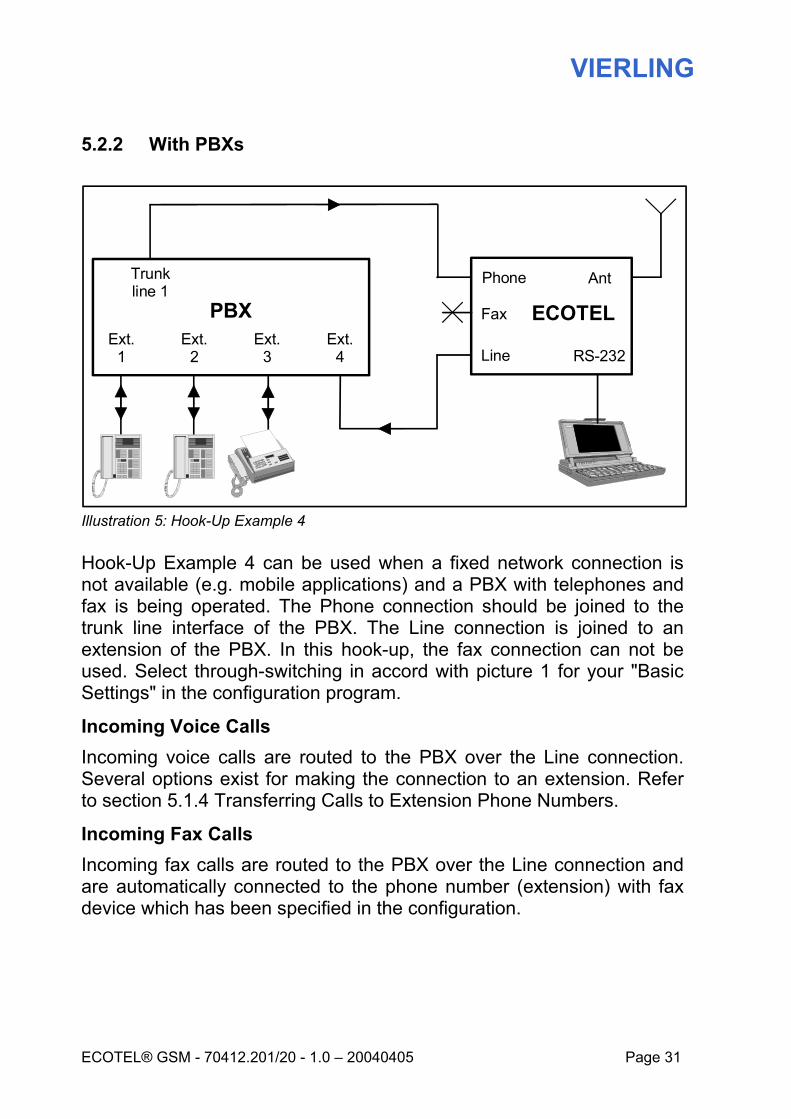
Illustration 5: Hook-Up Example 4
Hook-Up Example 4 can be used when a fixed network connection is not available (e.g. mobile applications) and a PBX with telephones and fax is being operated. The Phone connection should be joined to the trunk line interface of the PBX. The Line connection is joined to an extension of the PBX. In this hook-up, the fax connection can not be used. Select through-switching in accord with picture 1 for your "Basic Settings" in the configuration program.
Incoming Voice Calls Incoming voice calls are routed to the PBX over the Line connection. Several options exist for making the connection to an extension. Refer to section 5.1.4 Transferring Calls to Extension Phone Numbers.
Incoming Fax Calls Incoming fax calls are routed to the PBX over the Line connection and are automatically connected to the phone number (extension) with fax device which has been specified in the configuration.
Trunk line 1
PBXExt.
4Ext.
3Ext.
2Ext.
1
ECOTEL
AntPhone
Fax
Line RS-232
VIERLING
Page 32 70412.201/20 - 1.0 – 20040405 – ECOTEL® GSM3-1
Outgoing Voice Calls Outgoing voice calls can be made from any PBX extension. Dial the telephone number first, followed by the hatch (#) symbol.
Outgoing Fax Calls Outgoing faxes can be sent from any extension having a fax device. Dial the fax number first, followed by the star (*) symbol.
Advantages Telephoning procedures remain the same for all outgoing calls, since they are routed over the trunk line of the PBX to ECOTEL®GSM. Incoming calls are easily transferred to an extension since they are routed by ECOTEL®GSM over the Line connection to a PBX extension phone.
VIERLING
ECOTEL® GSM - 70412.201/20 - 1.0 – 20040405 Page 33
5.3 With Fixed Network Connections
5.3.1 Without PBXs
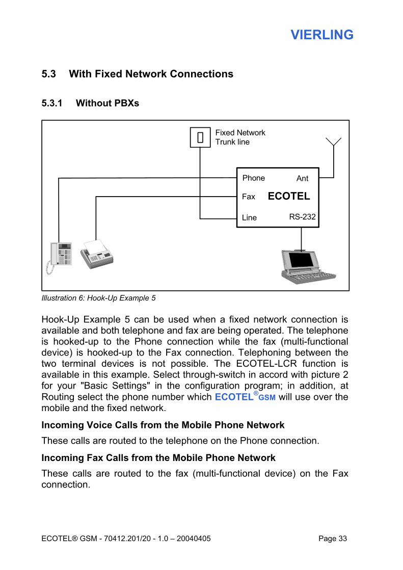
Illustration 6: Hook-Up Example 5
Hook-Up Example 5 can be used when a fixed network connection is available and both telephone and fax are being operated. The telephone is hooked-up to the Phone connection while the fax (multi-functional device) is hooked-up to the Fax connection. Telephoning between the two terminal devices is not possible. The ECOTEL-LCR function is available in this example. Select through-switch in accord with picture 2 for your "Basic Settings" in the configuration program; in addition, at Routing select the phone number which ECOTEL®GSM will use over the mobile and the fixed network.
Incoming Voice Calls from the Mobile Phone Network These calls are routed to the telephone on the Phone connection.
Incoming Fax Calls from the Mobile Phone Network These calls are routed to the fax (multi-functional device) on the Fax connection.
ECOTEL
AntPhone
Fax
Line
Fixed NetworkTrunk line
RS-232
VIERLING
Page 34 70412.201/20 - 1.0 – 20040405 – ECOTEL® GSM3-1
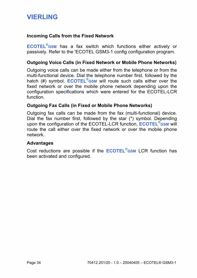
Incoming Calls from the Fixed Network
ECOTEL®GSM has a fax switch which functions either actively or passively. Refer to the 'ECOTEL GSM3-1 config configuration program.
Outgoing Voice Calls (in Fixed Network or Mobile Phone Networks) Outgoing voice calls can be made either from the telephone or from the multi-functional device. Dial the telephone number first, followed by the hatch (#) symbol. ECOTEL®GSM will route such calls either over the fixed network or over the mobile phone network depending upon the configuration specifications which were entered for the ECOTEL-LCR function.
Outgoing Fax Calls (in Fixed or Mobile Phone Networks) Outgoing fax calls can be made from the fax (multi-functional) device. Dial the fax number first, followed by the star (*) symbol. Depending upon the configuration of the ECOTEL-LCR function, ECOTEL®GSM will route the call either over the fixed network or over the mobile phone network.
Advantages Cost reductions are possible if the ECOTEL®GSM LCR function has been activated and configured.

VIERLING
ECOTEL® GSM - 70412.201/20 - 1.0 – 20040405 Page 35
5.3.2 With PBX
5.3.2.1 Manual LCR
Illustration 7: Hook-Up Example 6
Hook-Up Example 6 can be used when a fixed network connection is available and a PBX is being operated with telephones and a fax. The Line connection should be hooked-up to an extension of the PBX. Select through-switching in accord with picture 1 for your "Basic Settings" in the configuration program.
Incoming Voice Calls from the Mobile Phone Network Incoming voice calls are routed to the PBX over the Line connection. A number of options are available for transferring calls to a given extension (phone number). Refer to section 5.1.4 Transferring Calls to Extension Phone Numbers.
Incoming Fax Calls from the Mobile Phone Network Incoming fax calls are routed to the PBX over the Line connection and are automatically connected to the phone number (extension) with fax device which has been specified in the configuration.
Trunk line 1
PBXExt.
4Ext.
3Ext.
2Ext.
1
ECOTEL
Ant
Fixed NetworkTrunk line
Phone
Fax
Line RS-232
VIERLING
Page 36 70412.201/20 - 1.0 – 20040405 – ECOTEL® GSM3-1
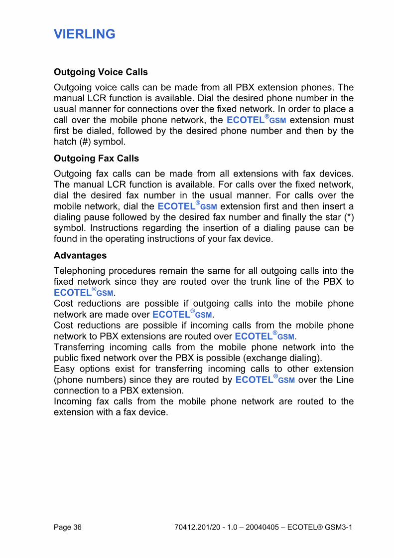
Outgoing Voice Calls Outgoing voice calls can be made from all PBX extension phones. The manual LCR function is available. Dial the desired phone number in the usual manner for connections over the fixed network. In order to place a call over the mobile phone network, the ECOTEL®GSM extension must first be dialed, followed by the desired phone number and then by the hatch (#) symbol.
Outgoing Fax Calls Outgoing fax calls can be made from all extensions with fax devices. The manual LCR function is available. For calls over the fixed network, dial the desired fax number in the usual manner. For calls over the mobile network, dial the ECOTEL®GSM extension first and then insert a dialing pause followed by the desired fax number and finally the star (*) symbol. Instructions regarding the insertion of a dialing pause can be found in the operating instructions of your fax device.
Advantages Telephoning procedures remain the same for all outgoing calls into the fixed network since they are routed over the trunk line of the PBX to ECOTEL®GSM. Cost reductions are possible if outgoing calls into the mobile phone network are made over ECOTEL®GSM. Cost reductions are possible if incoming calls from the mobile phone network to PBX extensions are routed over ECOTEL®GSM. Transferring incoming calls from the mobile phone network into the public fixed network over the PBX is possible (exchange dialing). Easy options exist for transferring incoming calls to other extension (phone numbers) since they are routed by ECOTEL®GSM over the Line connection to a PBX extension. Incoming fax calls from the mobile phone network are routed to the extension with a fax device.
VIERLING
ECOTEL® GSM - 70412.201/20 - 1.0 – 20040405 Page 37
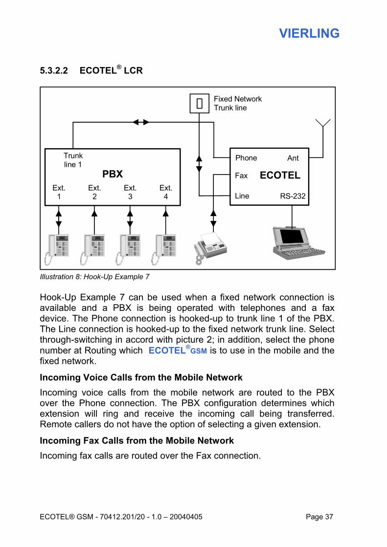
5.3.2.2 ECOTEL® LCR
Illustration 8: Hook-Up Example 7
Hook-Up Example 7 can be used when a fixed network connection is available and a PBX is being operated with telephones and a fax device. The Phone connection is hooked-up to trunk line 1 of the PBX. The Line connection is hooked-up to the fixed network trunk line. Select through-switching in accord with picture 2; in addition, select the phone number at Routing which ECOTEL®GSM is to use in the mobile and the fixed network.
Incoming Voice Calls from the Mobile Network Incoming voice calls from the mobile network are routed to the PBX over the Phone connection. The PBX configuration determines which extension will ring and receive the incoming call being transferred. Remote callers do not have the option of selecting a given extension.
Incoming Fax Calls from the Mobile Network Incoming fax calls are routed over the Fax connection.
Trunk line 1
PBXExt.
4Ext.
3Ext.
2Ext.
1
ECOTEL
Ant
Fixed NetworkTrunk line
Phone
Fax
Line RS-232
VIERLING
Page 38 70412.201/20 - 1.0 – 20040405 – ECOTEL® GSM3-1
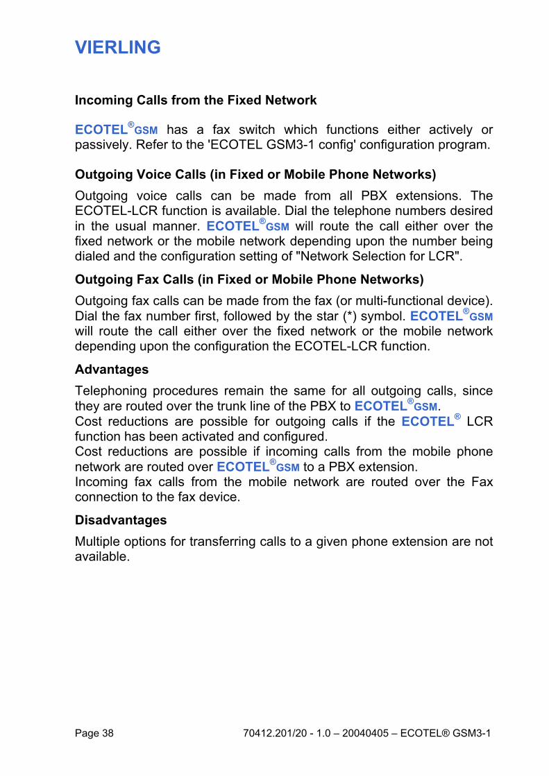
Incoming Calls from the Fixed Network
ECOTEL®GSM has a fax switch which functions either actively or passively. Refer to the 'ECOTEL GSM3-1 config' configuration program.
Outgoing Voice Calls (in Fixed or Mobile Phone Networks) Outgoing voice calls can be made from all PBX extensions. The ECOTEL-LCR function is available. Dial the telephone numbers desired in the usual manner. ECOTEL®GSM will route the call either over the fixed network or the mobile network depending upon the number being dialed and the configuration setting of "Network Selection for LCR".
Outgoing Fax Calls (in Fixed or Mobile Phone Networks) Outgoing fax calls can be made from the fax (or multi-functional device). Dial the fax number first, followed by the star (*) symbol. ECOTEL®GSM will route the call either over the fixed network or the mobile network depending upon the configuration the ECOTEL-LCR function.
Advantages Telephoning procedures remain the same for all outgoing calls, since they are routed over the trunk line of the PBX to ECOTEL®GSM. Cost reductions are possible for outgoing calls if the ECOTEL® LCR function has been activated and configured. Cost reductions are possible if incoming calls from the mobile phone network are routed over ECOTEL®GSM to a PBX extension. Incoming fax calls from the mobile network are routed over the Fax connection to the fax device.
Disadvantages Multiple options for transferring calls to a given phone extension are not available.
VIERLING
ECOTEL® GSM - 70412.201/20 - 1.0 – 20040405 Page 39
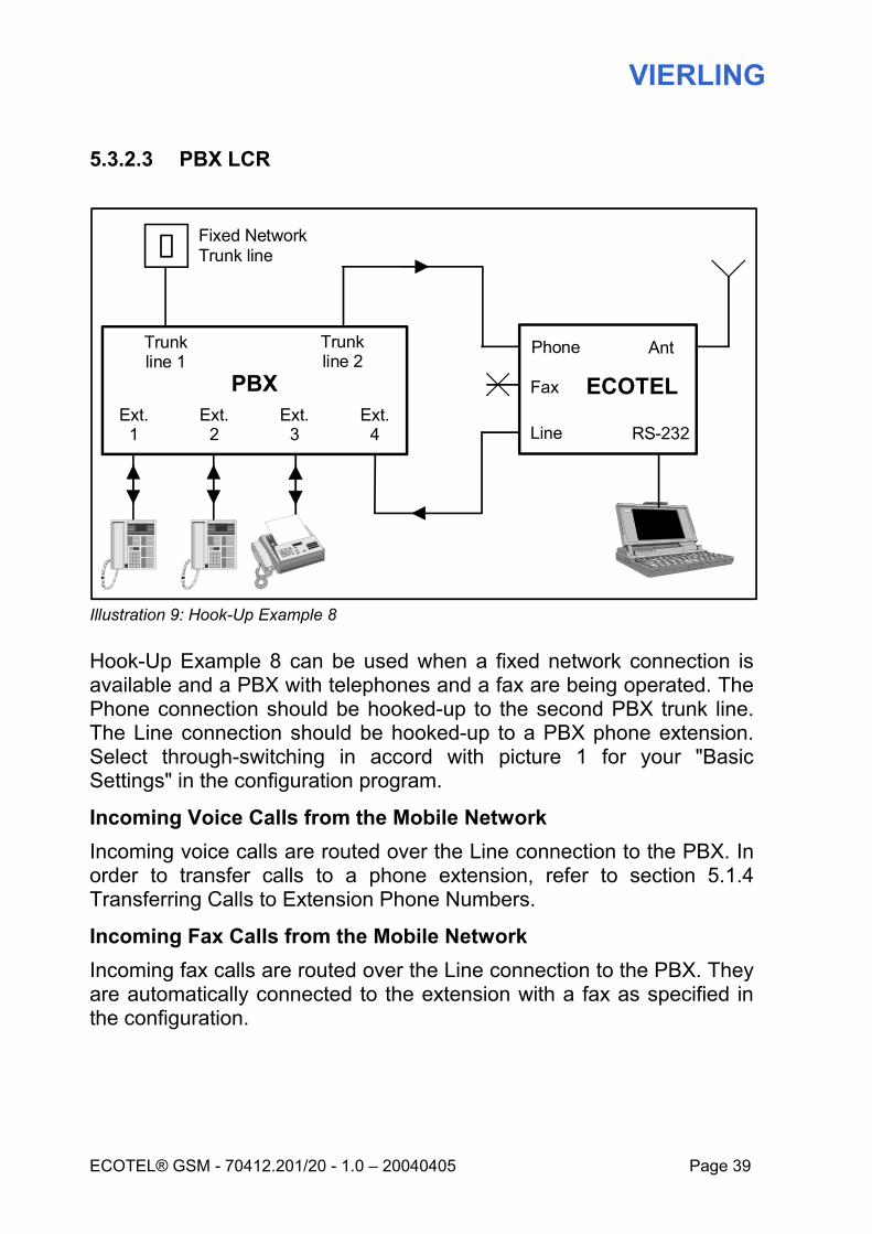
5.3.2.3 PBX LCR
Illustration 9: Hook-Up Example 8
Hook-Up Example 8 can be used when a fixed network connection is available and a PBX with telephones and a fax are being operated. The Phone connection should be hooked-up to the second PBX trunk line. The Line connection should be hooked-up to a PBX phone extension. Select through-switching in accord with picture 1 for your "Basic Settings" in the configuration program.
Incoming Voice Calls from the Mobile Network Incoming voice calls are routed over the Line connection to the PBX. In order to transfer calls to a phone extension, refer to section 5.1.4 Transferring Calls to Extension Phone Numbers.
Incoming Fax Calls from the Mobile Network Incoming fax calls are routed over the Line connection to the PBX. They are automatically connected to the extension with a fax as specified in the configuration.
Trunk line 1
PBXExt.
4Ext.
3Ext.
2Ext.
1
ECOTEL
Ant
Fixed NetworkTrunk line
Phone
Fax
Line
Trunk line 2
RS-232

VIERLING
Page 40 70412.201/20 - 1.0 – 20040405 – ECOTEL® GSM3-1
Outgoing Voice Calls Outgoing voice calls can be made from all PBX phone extensions. The LCR function of the PBX is used in this regard. Dial the desired phone number as usual. The PBX will route the call to trunk line 1 or trunk line 2 in accord with the number being dialed and with the PBX configuration. ECOTEL®GSM will route all calls from trunk line 2 into the mobile phone network.
Outgoing Fax Calls Outgoing fax calls can be made from the extension with fax capabilities. The LCR function of the PBX is utilized in this regard. Dial the desired number in the usual manner. The PBX will then route the call either to trunk line 1 or to trunk line 2 depending upon the number dialed and the PBX configuration. ECOTEL®GSM will route all calls from trunk line 2 into the mobile phone network.
Advantages Telephoning procedures remain the same for all outgoing calls, since they are routed over PBX trunk line 2 to ECOTEL®GSM. Cost reductions are possible for outgoing calls if the LCR function of the PBX has been activated and configured. Cost reductions are possible if incoming calls from the mobile phone network are routed over ECOTEL®GSM to a PBX extension. Easy options exist for transferring incoming calls to other extension (phone numbers) since they are routed by ECOTEL®GSM over the Line connection to an extension of the PBX.

VIERLING
ECOTEL® GSM - 70412.201/20 - 1.0 – 20040405 Page 41
6. Operations
6.1 Configuring ECOTEL®GSM
Before it can be put in to operation, ECOTEL®GSM must be configured using the ECOTEL GSM3-1 config configuration program. At the menu entry "Extras - Gateway Configuration" settings can be made for data transfers. You can choose between serial interface (data transfer with local ECOTEL®GSM) and mobile network (data transfer with remote ECOTEL®GSM).
6.1.1 Local Configuration
Enter the serial Interface gateway configuration.
6.1.2 Remote Configuration
Enter the mobile network gateway configuration. For this gateway, the data transfer provider for the SIM card of the remote ECOTEL®GSM must be cleared (by data transfer you get an extra call number). Moreover, a local ECOTEL®GSM (GSM3-1, regardless of which type) is required on the serial interface of the laptop. Assisted by this ECOTEL®GSM , the data transfer can be executed with the remote ECOTEL®GSM. Access to the remote ECOTEL®GSM is only possible by using a code. If the IMEI of the remote ECOTEL®GSM is known (available in the shipping documents), then access to ECOTEL®GSM is also available. As code for the remote ECOTEL®GSM, enter the first 2 and the last 6 digits of the IMEI.
6.2 Outgoing Calls
Outgoing calls are connections to remote subscribers made by ECOTEL®GSM into the fixed or mobile networks.
VIERLING
Page 42 70412.201/20 - 1.0 – 20040405 – ECOTEL® GSM3-1
For outgoing calls, ECOTEL®GSM only begins to dial a number after it has been completely entered. For voice connections, after inputting the desired number, the caller then enters the hatch (#) symbol to complete the dialing procedure. For fax connections, after inputting the desired number, the user then enters the star (*) symbol. If the respective symbol is not entered, then the time criterion or the digit criterion becomes effective. Dialing can begin immediately even if a voice message has been activated. No waiting is necessary.
6.3 Incoming calls
Incoming calls are calls received by ECOTEL®GSM from remote subscribers. Dialing can begin immediately even if a voice message has been activated. No waiting is necessary.
6.3.1 Incoming calls from Mobile Networks
If ECOTEL®GSM is connected to a PBX extension over the Line connection, then remote callers have several options for transferring their calls to a given extension. Option 1 (Immediate Through-Switch)
External callers dial the ECOTEL®GSM mobile phone number and are then automatically connected to a configured extension. Option 2 (Delayed Through-Switch)
External callers dial the ECOTEL®GSM mobile phone number and then have the option of suffix-dialing the desired extension within a given time interval. If suffix-dialing does not take place within this interval, then the external caller will be connected to a configured extension. At the end of a call, or if the number is busy or unavailable, the caller still has the option of suffix-dialing to any other extension.
ECOTEL®GSM also offers the option of suffix-dialing into the public fixed network if the extension connection is hooked-up to ECOTEL®GSM and if it is also authorized for direct outward dialing. Direct dialing into the
VIERLING
ECOTEL® GSM - 70412.201/20 - 1.0 – 20040405 Page 43
public network must be authorized in the configuration ("Authorization"). Remote callers assume charges for connections to ECOTEL®GSM and the ECOTEL®GSM operator assumes charges for connections from ECOTEL®GSM into the public fixed network. Thus, the phone extension configured for Options 1 and 2 can also be a telephone number in the fixed network.

VIERLING
Page 44 70412.201/20 - 1.0 – 20040405 – ECOTEL® GSM3-1
7. Serial Interface RS-232
The following applications can be run over the ECOTEL®GSM serial interface:
• Configuration of ECOTEL®GSM with ECOTEL GSM3-1 config • Sending and receiving SMSs with ECOTEL SMeaSy Pro • Sending and receiving faxes with WinFax Pro • Internet Browsing with Internet Explorer
A non-crossed serial cable must be used.
7.1 Configuring ECOTEL
ECOTEL®GSM is already pre-configured with a standard configuration. The ECOTEL GSM3-1 config configuration program should be used to adjust the configuration to your specific needs. Details about this procedure can be found in the online help of ECOTEL GSM3-1 config.
7.2 Sending and Receiving SMSs
ECOTEL®GSM supports sending and receiving SMS messages. ECOTEL SMeaSy Pro is an SMS application designed for this purpose and has been included in the product package. Details about the program can be found in ECOTEL SMeaSy Pro operating instructions. ECOTEL®GSM operates at a speed of 19200 bps on a serial interface. Settings for SMeaSy Pro should be made accordingly.
7.3 Sending and Receiving Faxes with PCs
ECOTEL®GSM supports sending and receiving faxes with a PC over a serial interface. The WinFax Pro application from Symantec is required for this purpose. It is not included in the product package. Install WinFax Pro on your PC. For this procedure, follow the instructions provided by WinFax Pro and operating instructions for modem driver and remote data transmission.
VIERLING
ECOTEL® GSM - 70412.201/20 - 1.0 – 20040405 Page 45
7.3.1 Sending Faxes
ECOTEL®GSM voice-function features are not available when faxes are being dispatched or received. Procedures for sending and receiving faxes with WinFax PRO is described in the WinFax PRO operating instructions. When a PC fax-connection is being set-up, the yellow "Data" and "Fax" LEDs will blink. During fax transmission from the PC, both LEDs will remain lighted. Comment: When setting up an analog fax connection with a fax device, the yellow "Fax" LED will blink. During analog fax transmission, the LED will remain lighted.
7.3.2 Receiving Faxes
ECOTEL®GSM voice-function features are not available when faxes are being dispatched and received. Procedures for Incoming FAXES: If a PC is not connected to the serial interface, then the fax (ring) will be routed to the Line connection. If a PC is connected to the serial interface, then the fax (ring) will be routed to the serial interface of ECOTEL®GSM. If an application (e.g. WinFax PRO) is running on the PC which accepts the fax-ring, then this application will accept the incoming fax. If no application is running on the PC that accepts the fax-ring, then the fax-ring will be through-switched to the Line connection and fax after the third ring.
7.4 Internet Access
ECOTEL®GSM supports internet browsing over an internet ISP access number into the GSM mobile network. This requires the Internet Explorer program from Microsoft which is not included in the program package. Install Internet Explorer on your PC. Follow the information provided in these operating instructions and operating instructions “Modem Driver and Remote Data Transmission (RDT)”.

VIERLING
Page 46 70412.201/20 - 1.0 – 20040405 – ECOTEL® GSM3-1
8. Technical Data
8.1 General Specifications
Height x Width x Depth: 63 mm x 185 mm x 255 mm
Weight: 650 grams
Power Supply Unit: primary 100 - 240 volt AC, 47 - 63 Hz secondary: 15 volt DC/1.5 A
Current Consumption: about 3 watts (stand-by) about 5 watts (for calls)
Input Voltage 9 to 24 volts DC/< 1.5 A
Operating Temperatures: -20 to +55 °C
Storage Temperatures: -30 to +70 °C
Relative Humidity: 5 - 95 % non-condensing
FXO Line: Call Recognition: Impedance:
> 20 volt, 20 to 60 Hz, pulse > 125 ms Zr in accord with CTR 21
FXS Phone: Ringer: Current Feeding: Impedance: Charge-Metering Pulse:
> 38 Volt AC at 25 Hz on 1 µF and 2 kΩ U no-load typ. 35 volt, I typ. = 25 mA Zr in accord with CTR 21 16 kHz, 12 kHz, polarity change
FXS Fax: Wire Assignment: Ringer: Current Feeding: Impedance:
RJ12, 3=a-wire, 4=b-wire > 38 volt AC at 25 Hz on 1 µF and 2 kΩ U no-load typ. 35 volt, I typ. = 25 mA Zr in accord with CTR 21
Antenna: SMA, FME (adapter included) Serial Interface: 9-pole D-SUB, RS-232 (19200 bps, 8 N 1) cable
not crossed
VIERLING
ECOTEL® GSM - 70412.201/20 - 1.0 – 20040405 Page 47
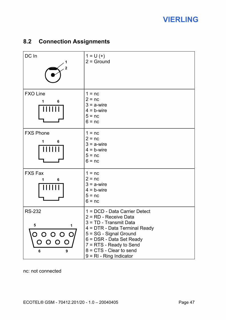
8.2 Connection Assignments
DC In
1 = U (+) 2 = Ground
FXO Line
1 = nc 2 = nc 3 = a-wire 4 = b-wire 5 = nc 6 = nc
FXS Phone
1 = nc 2 = nc 3 = a-wire 4 = b-wire 5 = nc 6 = nc
FXS Fax
1 = nc 2 = nc 3 = a-wire 4 = b-wire 5 = nc 6 = nc
RS-232
1 = DCD - Data Carrier Detect 2 = RD - Receive Data 3 = TD - Transmit Data 4 = DTR - Data Terminal Ready 5 = SG - Signal Ground 6 = DSR - Data Set Ready 7 = RTS - Ready to Send 8 = CTS - Clear to send 9 = RI - Ring Indicator
nc: not connected
15
6 9
1 6
1 6
1 6
12
VIERLING
Page 48 70412.201/20 - 1.0 – 20040405 – ECOTEL® GSM3-1
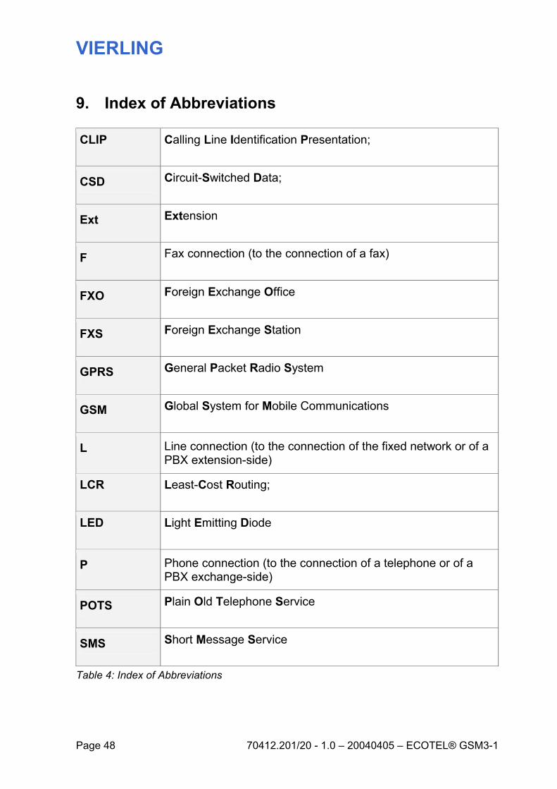
9. Index of Abbreviations
CLIP Calling Line Identification Presentation;
CSD Circuit-Switched Data;
Ext Extension
F Fax connection (to the connection of a fax)
FXO Foreign Exchange Office
FXS Foreign Exchange Station
GPRS General Packet Radio System
GSM Global System for Mobile Communications
L Line connection (to the connection of the fixed network or of a PBX extension-side)
LCR Least-Cost Routing;
LED Light Emitting Diode
P Phone connection (to the connection of a telephone or of a PBX exchange-side)
POTS Plain Old Telephone Service
SMS Short Message Service
Table 4: Index of Abbreviations
VIERLING
ECOTEL® GSM - 70412.201/20 - 1.0 – 20040405 Page 49
VIERLING
Page 50 70412.201/20 - 1.0 – 20040405 – ECOTEL® GSM3-1