69-1960E-01 A Retrofit Round Damper - Honeywell › resources › techlit › TechLit... ·...
8
PRODUCT DATA 69-1960ES-01 Retrofit Round Damper (RRD) APPLICATION The RRD is a round damper that is easily inserted into rigid round ducts for retrofit zoning in forced air heating and cooling systems. It is available in four sizes for use in 5”, 6”, 7”, and 8” ducts. The damper is used with Honeywell TrueZONE®, EnviraZONE™ and similar zone control systems. The power open, power closed actuator draws 2 VA allowing multiple dampers per zone, but delivers high torque for reliable operation. FEATURES • Easy slide-in installation • 2 VA allows for many dampers on one zone • Available in 4 sizes to fit most rigid round branch ducts • Quiet, long life motor automatically shuts itself off in full open and closed positions. • Gaskets around blade and under motor housing for low internal leakage and very low external leakage • Range stops with easy adjustment from top of motor • Easy to see and reliable mechanical blade position indicator • Easy to hook up with conventional thermostat wire • Simple manual blade positioning with push button gear release SPECIFICATIONS IMPORTANT The specifications given in this manual do not include normal manufacturing tolerances. Therefore, this unit may not exactly match the listed specifica- tions. In addition, this product is tested and calibrated under closely controlled conditions, and some minor differences in performance can be expected if those conditions are changed. Contents Application ........................................................................ 1 Features ........................................................................... 1 Specifications ................................................................... 1 Ordering Information ......................................................... 2 Installation ........................................................................ 3 Wiring ............................................................................... 3 Adjustments ...................................................................... 4 Checkout .......................................................................... 4 Troubleshooting ................................................................ 4
Transcript of 69-1960E-01 A Retrofit Round Damper - Honeywell › resources › techlit › TechLit... ·...

PRODUCT DATA
69-1960ES-01
Retrofit Round Damper (RRD)
APPLICATIONThe RRD is a round damper that is easily inserted into rigid round ducts for retrofit zoning in forced air heating and cooling systems. It is available in four sizes for use in 5”, 6”, 7”, and 8” ducts.
The damper is used with Honeywell TrueZONE®, EnviraZONE™ and similar zone control systems. The power open, power closed actuator draws 2 VA allowing multiple dampers per zone, but delivers high torque for reliable operation.
FEATURES• Easy slide-in installation• 2 VA allows for many dampers on one zone• Available in 4 sizes to fit most rigid round branch ducts• Quiet, long life motor automatically shuts itself off in
full open and closed positions.• Gaskets around blade and under motor housing for
low internal leakage and very low external leakage• Range stops with easy adjustment from top of motor• Easy to see and reliable mechanical blade position
indicator• Easy to hook up with conventional thermostat wire• Simple manual blade positioning with push button
gear release
SPECIFICATIONSIMPORTANT
The specifications given in this manual do not include normal manufacturing tolerances. Therefore, this unit may not exactly match the listed specifica-tions. In addition, this product is tested and calibrated under closely controlled conditions, and some minor differences in performance can be expected if those conditions are changed.
ContentsApplication ........................................................................ 1Features ........................................................................... 1Specifications ................................................................... 1Ordering Information ......................................................... 2Installation ........................................................................ 3Wiring ............................................................................... 3Adjustments ...................................................................... 4Checkout .......................................................................... 4Troubleshooting ................................................................ 4

RETROFIT ROUND DAMPER (RRD)
69-1960ES—01 2
ORDERING INFORMATIONWhen purchasing replacement and modernization products from your TRADELINE® wholesaler or distributor, refer to the TRADELINE® Catalog or price sheets for complete ordering number.
If you have additional questions, need further information, or would like to comment on our products or services, please write or phone:
1. Your local Honeywell Automation and Control Products Sales Office (check white pages of your phone directory).2. Honeywell Customer Care
1885 Douglas Drive NorthMinneapolis, Minnesota 55422-4386
In Canada—Honeywell Limited/Honeywell Limitée, 35 Dynamic Drive, Toronto, Ontario M1V 4Z9.International Sales and Service Offices in all principal cities of the world. Manufacturing in Australia, Canada, Finland, France, Germany, Japan, Mexico, Netherlands, Spain, Taiwan, United Kingdom, U.S.A.
ConstructionFrame: 18 gauge G-60 or G-90 galvanized steel C channel
with gasket, 20 gauge actuator mounting bracket.Blade: 20 gauge G-60 or G-90 galvanized steel surrounded by
a black EPDM rubber gasket.Shaft: 1/2” hex damper blade shaft of cold rolled zinc electro-
plated steel. The shaft runs through a white nylon bushing.Sizes: 5.125”, 6.125”, 7.125”, 8.125” diameters
Electrical Rating: 24 VAC, 50 or 60 Hz
Power Consumption: 1.5 watts running. Transformer sizing VA: 2.
Wiring Terminals: Screw terminals for 14 to 26 gauge wire labeled: M1 (Common), M4 (counter-clockwise, open), M6 (clockwise, closed)
Nominal Angular Rotation: 90°
Torque: 45 in. lb, (5 Nm)
Nominal Timing: 90 seconds independent of load
Ambient Ratings: -40° F (-40° C) to 122° F (50° C), 5-95% RH non-condensing
Mounting: Direct couple to 1/2” shaft
Agency Listings: NEMA 1, UL listed, class two
Dimensions: See Fig. 1–2
Weight: RRD5: 3.6 lbRRD6: 3.8 lbRRD7: 4.1 lbRRD8: 4.3 lb
Leakage (Closed): 3.4% at .5” WC
Pressure Drop (Open): <.05” WC
Fig. 1. Motor dimensions in in. (mm).
Fig. 2. RRD damper.
NE
MA
1
1
0
M31212A
2-19/32(66)
57/64(22)
3-5/8(92)
MANUAL BLADE RELEASE
ROTATION DIRECTION
RANGE STOPS
2-9/32(58)
7/32 (5.55)
2-9/32(58)
4-33/64(114.7)
WIRINGTERMINALS
POSITION INDICATOR
NE
MA
1
M31213
10-3/4 (273)
2-3/4(70)
5-3/8 (137)
2-5/8(67)
1/2 (13)
1/2(13)

RETROFIT ROUND DAMPER (RRD)
3 69-1960ES—01
INSTALLATIONBefore Installing this Product
1. Read all instructions before installing this product. Fail-ure to follow instructions can damage the product or cause a hazardous condition.
2. Check the ratings given in the instructions and on the product to verify that the product is suitable for your application.
3. Installer must be a trained and experienced service tech-nician.
4. Install the product in an area that is easily accessible for checkout and service.
5. After completing installation, use these instructions to check out product operation.
Installing the Retrofit Round DamperSelect a location for the damper in the ductwork. It is suggested that the RRD damper be at least 6 feet from the register for quiet operation.
1. Peel off the back of the cut-out template. Carefully align the template with the centerline of the duct. Apply tem-plate to the section of round ductwork where the damper is to be installed. Ensure that the template is parallel to the ductwork. It is suggested that the damper be installed with the motor under a horizontal duct to reduce twist to the duct. It may also be necessary to support the duct.
2. Drill a starter hole in the cut-out area of the template.3. Cut out the area between the holes.4. Slide the damper into the duct and secure it with the four
supplied self-drilling mounting screws. Be careful to avoid over-tightening the screws as the duct may be pulled out of round. See Fig. 3.
Fig. 3. Inserting RRD damper into duct.
WIRINGWiring the Motor ActuatorConnect the motor to the zone control panel 18 or 20 gauge wire. The motor terminals are labeled M1 for common, M4 for open, and M6 for closed. Connect the motor terminals to corresponding terminals on zone control panel for each zone. See Fig. 4–6 for hookups.
Multiple RRD dampers can be wired to one zone when wired in parallel. See Fig. 5 for wiring multiple dampers together in a daisy chain manner or Fig. 6 using wire nuts. See Table 1 for
the maximum number of dampers that can be connected to each zone control panel. Note that this is the total number of dampers connected to all the zones of a zone control panel; the maximum dampers per zone is 14. If more than 14 dampers are on one zone, a Slave Damper Control Relay (SDCR) must be used.
When more than the maximum number of dampers allowed per panel are necessary, a SDCR must be used. The SDCR is an isolation relay that is powered by a separate transformer so that it relieves the panel of this additional load. When a SDCR is used, the dampers of that zone may either be all connected to the SDCR, or some dampers may be wired to the SDCR and the remainder to that zone’s damper terminals.
*Maximum of 14 dampers per zone
Fig. 4. RRD wired to zone control panel.
Fig. 5. Wiring multiple RRD dampers in daisy chain fashion.
M31220
Maximum number of dampers per zone.
One 40 VA Transformer
Two 40 VA Transformers (or
One 75 VA)TrueZONE® Panels* 13 27W8835* 12 26SDCR 15 28
R Y W G C M6 M4 M1
R Y W G
ZONE 1, 2, 3, ETC.
M1M4M6
M31217
ZONETHERMOSTAT
R Y W G C M6 M4 M1
R Y W G
ZONE 1, 2, 3, ETC.
M 1
M 4M 6
M1 M4M6
M31218
ZONE THERMOSTAT

RETROFIT ROUND DAMPER (RRD)
Automation and Control SolutionsHoneywell International Inc.1985 Douglas Drive NorthGolden Valley, MN 55422
Honeywell Limited-Honeywell Limitée35 Dynamic DriveToronto, Ontario M1V 4Z9customer.honeywell.com
® U.S. Registered Trademark© 2010 Honeywell International Inc.69-1960ES—01 E.K. Rev. 02-10 Printed in U.S.A.
Fig. 6. Wiring multiple RRD dampers using wire nuts.
ADJUSTMENTSManual Blade AdjustmentTo verify correct range of motion, depress the manual blade adjustment button. While this is pressed, the gears are disengaged, allowing the blade to be manually opened or closed by turning the damper blade shaft. See Fig. 1.
Position IndicatorThe position indicator (shown in Figure 1) points toward the position of the damper blade to identify if the blade is open, closed, or at an intermediate position. A slot at the end of the damper blade shaft also indicates blade position.
Range stopsThe RRD damper motor can be adjusted to prevent complete closure of the blade. This is useful in zone systems where it is not possible to install a bypass damper.
To set the range stop to prevent complete closure:
1. Locate the range stop adjustment screw on the top of the motor to the right blade shaft. This is at the extreme counter-clockwise end of travel.
2. Using a small Phillips head screwdriver, loosen the set screw.
3. Move the end-stop block to the new position4. Secure the set screw.5. Verify the new range of motion while depressing the
manual blade release button.
Rotation Direction AdjustmentThe rotation direction screw (Shown in Figure 1) reverses the direction the damper operates. It should be left in the "0" position to open when M4 is powered and close when M6 is powered.
CHECKOUT
CAUTIONPossible Equipment DamageDo not manually open or close the damper unless the manual blade release button is depressed.
To check out the RRD damper using 24 VAC transformer:
1. Connect 24 VAC common to the M1 (common) terminal on the actuator.
2. Connect 24 VAC hot to the M6 terminal to closethe damper.
3. Observe the blade move clockwise and stop in the closed position.
4. Remove the 24 VAC hot wire from the M6 terminal.5. Connect the 24 VAC hot wire to the M4 terminal.6. Observe the blade move counter-clockwise and stop in
the open position.7. This verifies correct operation.
Alternatively, if the damper is wired to a TrueZONE HZ432 or HZ322 panel, the damper checkout process may be used to verify damper operation.
TROUBLESHOOTING
R Y W G C M6 M4 M1
R Y W G
ZONE 1, 2, 3, ETC.
M1 M4M6
M1 M4M6
M31219
ZONE THERMOSTAT
WIRE NUT
Damper operates backwards Verify correct damper wiring as shown in Fig. 4–6. Also verify that the Rotation Direction screw is in the "0" position as shown in Figure 1.
Damper does not operate 1. Verify damper wiring using checkout methods listed in this document.2. Verify that the duct is round and not making the blade stick. Depress the
manual blade release button and manually turn the blade shaft to verify smooth opening and closing operation.

INFORMACIÓN DEL PRODUCTO
69-1960ES-01
Regulador circular de retro-instalación (RRD)
APLICACIÓNEl RRD es un regulador circular que se inserta fácilmente en conductos rígidos y circulares para realizar retroinstalaciones en sistemas de calefacción y refrigeración forzados. Está disponible en cuatro tamaños para utilizar en conductos de 5, 6, 7 y 8 pulgadas.
El regulador se utiliza con TrueZONE®, EnviraZONE™ de Honeywell y con sistemas similares de control de zona. El accionador de apertura o cierre de la energía quita 2 VA, lo que permite tener varios reguladores por zona, pero brinda un alto par de torsión para un funcionamiento confiable.
CARACTERÍSTICAS• Fácil instalación por deslizamiento• Al utilizar 2 VA permite varios reguladores en la misma
zona• Disponible en cuatro tamaños para adaptarse a la
mayoría de los conductos rígidos, de bifurcaciones redondeadas
• Motor silencioso, de prolongada vida útil, con apagado automático cuando se encuentra en posición completamente abierta o cerrada
• Juntas alrededor de la cuchilla y debajo de la carcasa del motor para proteger contra pequeñas fugas internas y muy pequeñas fugas externas
• El rango se detiene con un fácil ajuste desde la parte superior del motor
• Indicador mecánico de posición de la cuchilla fácil de ver y confiable
• Fácil de acoplar con el cable convencional del termostato
• Simple posicionamiento manual de la cuchilla mediante la liberación del engranaje con sólo apretar un botón
ESPECIFICACIONESIMPORTANTE
Las secciones que aparecen en este manual no incluyen las tolerancias normales de fabricación. Por lo tanto, esta unidad puede no coincidir exactamente con las especificaciones enumeradas. Además, este producto ha sido probado y calibrado en condiciones de máximo control, y pueden encontrarse pequeñas diferencias en el rendimiento si se modifican dichas condiciones.
ContenidosAplicación ......................................................................... 1Características ................................................................. 1Especificaciones ............................................................... 1Información para Pedidos ................................................. 2Instalación ........................................................................ 3Cableado .......................................................................... 3Ajustes .............................................................................. 4Revisión ............................................................................ 4Solución de Problemas .................................................... 4

REGULADOR CIRCULAR DE RETRO- INSTALACIÓN (RRD)
69-1960ES—01 2
INFORMACIÓN PARA PEDIDOSCuando compre productos de reemplazo y modernización a su mayorista o distribuidor de TRADELINE®, refiérase al catálogo o listas de precios de TRADELINE® para tener el número de pedido completo.Si tiene preguntas adicionales, si necesita más información, o si quisiera dar sus comentarios sobre nuestros productos o servicios, escriba o llame a:
1. Su oficina de ventas local de Automatización y control de Honeywell (consulte las páginas blancas de su directorio telefónico)
2. Honeywell Customer Care1885 Douglas Drive NorthGolden Valley, MN 55422-4386
En Canadá : Honeywell Limited/Honeywell Limitée, 35 Dynamic Dr., Toronto, Ontario, M1V 4Z9. Oficinas internacionales de ventas y servico en todas las principales ciudades de mundo. Manufactura en Australia, Canadá, Finlandia, Francia, Alemania, Japón, México, los Países Bajos, España, Taiwán, Reino Unido, EE, UU.
ConstrucciónEstructura: G-60 o G-90 calibre 18, con canal C de acero gal-
vanizado con junta, soporte para montaje del accionador de calibre 20.
Cuchilla: G-60 o G-90 calibre 20, de acero galvanizado rodeado por una junta de caucho EPDM negro.
Eje: eje hexagonal de la cuchilla del regulador de 1/2”, de acero galvanoplastiado de zinc laminado en frío. El eje atraviesa un cojinete de nailon blanco.
Tamaños: Diámetros de 5,125", 6,125", 7,125", 8,125"
Rangos eléctricos: 24 V CA, 50 ó 60 Hz
Consumo de energía: 1,5 W en funcionamiento; Clasifi-cación del transformador en VA: 2.
Terminales de cableado: Terminales de tornillo para el cable calibre 14 a 26 identificado como: M1 (Común), M4 (sen-tido antihorario, abierto), M6 (sentido horario, cerrado).
Rotación angular nominal: 90°
Par de torsión: 45 pulgada-libra, (5 Nm)
Sincronización nominal: 90 segundos, independiente-mente de la carga
Clasificación ambiental: -40 °F (-40 °C) a 122 °F (50 °C), 5-95% de HR sin condensación
Montaje: Acoplamiento directo sobre eje de 1/2 pulgada.
Certificación del organismo: NEMA 1, certificación UL, clase dos
Dimensiones: Vea la Fig. 1–2
Peso: RRD5: 3,6 lbRRD6: 3,8 lbRRD7: 4,1 lbRRD8: 4,3 lb
Fuga (cerrado): 0,05 columna de agua (WC)
Caída de presión (abierto): < 0,5 columna de agua (WC)
Fig. 1. Dimensiones del motor en (mm) pulgadas.
Fig. 2. regulador RRD.
NE
MA
1
MS31212A
66(2-19/32)
22(57/64)
92(3-5/8)
LIBERACIÓN MANUALDE LA CUCHILLA
TOPES PARA RANGOS
58(2-9/32)
5.55 (7/32)
58(2-9/32)
114.7(4-33/64)
TERMINALESDE CABLEADO
NE
MA
1
1
0
DIRECCIÓN DE LA ROTACIÓN
INDICADOR DE POSICIÓN
NE
MA
1
MS31213
273 (10-3/4)
70(2-3/4)
137 (5-3/8)
67(2-5/8)
13 (1/2)
13(1/2)
REGULADOR CIRCULAR DE RETRO- INSTALACIÓN (RRD)
3 69-1960ES—01
INSTALACIÓNAntes de instalar este producto
1. Lea todas las instrucciones antes de instalar este pro-ducto. Si no sigue estas instrucciones, puede dañar el producto u ocasionar un riesgo.
2. Revise las clasificaciones brindadas en las instrucciones y en el producto para verificar que sea adecuado para la aplicación que necesita.
3. La persona que instale el producto debe ser un técnico entrenado y experimentado.
4. Instale el producto en un área de fácil acceso para la revisión y el mantenimiento.
5. Después de completar la instalación, use estas instruc-ciones para revisar el funcionamiento del producto.
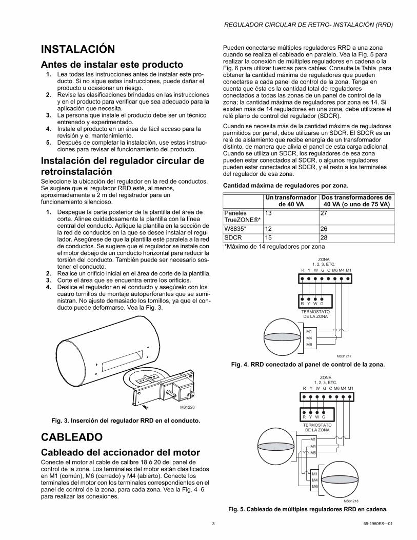
Instalación del regulador circular de retroinstalaciónSeleccione la ubicación del regulador en la red de conductos. Se sugiere que el regulador RRD esté, al menos, aproximadamente a 2 m del registrador para un funcionamiento silencioso.
1. Despegue la parte posterior de la plantilla del área de corte. Alinee cuidadosamente la plantilla con la línea central del conducto. Aplique la plantilla en la sección de la red de conductos en la que se desee instalar el regu-lador. Asegúrese de que la plantilla esté paralela a la red de conductos. Se sugiere que el regulador se instale con el motor debajo de un conducto horizontal para reducir la torsión del conducto. También puede ser necesario sos-tener el conducto.
2. Realice un orificio inicial en el área de corte de la plantilla.3. Corte el área que se encuentra entre los orificios.4. Deslice el regulador en el conducto y asegúrelo con los
cuatro tornillos de montaje autoperforantes que se sumi-nistran. No ajuste demasiado los tornillos, ya que el con-ducto puede deformarse. Vea la Fig. 3.
Fig. 3. Inserción del regulador RRD en el conducto.
CABLEADOCableado del accionador del motorConecte el motor al cable de calibre 18 ó 20 del panel de control de la zona. Los terminales del motor están clasificados en M1 (común), M6 (cerrado) y M4 (abierto). Conecte los terminales del motor con los terminales correspondientes en el panel de control de la zona, para cada zona. Vea la Fig. 4–6 para realizar las conexiones.
Pueden conectarse múltiples reguladores RRD a una zona cuando se realiza el cableado en paralelo. Vea la Fig. 5 para realizar la conexión de múltiples reguladores en cadena o la Fig. 6 para utilizar tuercas para cables. Consulte la Tabla para obtener la cantidad máxima de reguladores que pueden conectarse a cada panel de control de la zona. Tenga en cuenta que ésta es la cantidad total de reguladores conectados a todas las zonas de un panel de control de la zona; la cantidad máxima de reguladores por zona es 14. Si existen más de 14 reguladores en una zona, debe utilizarse el relé plano de control del regulador (SDCR).
Cuando se necesita más de la cantidad máxima de reguladores permitidos por panel, debe utilizarse un SDCR. El SDCR es un relé de aislamiento que recibe energía de un transformador distinto, de manera que alivia el panel de esta carga adicional. Cuando se utiliza un SDCR, los reguladores de esa zona pueden estar conectados al SDCR, o algunos reguladores pueden estar conectados al SDCR, y el resto a los terminales del regulador de esa zona.
Fig. 4. RRD conectado al panel de control de la zona.
Fig. 5. Cableado de múltiples reguladores RRD en cadena.
M31220
Cantidad máxima de reguladores por zona.
Un transformador de 40 VA
Dos transformadores de 40 VA (o uno de 75 VA)
Paneles TrueZONE®*
13 27
W8835* 12 26SDCR 15 28*Máximo de 14 reguladores por zona
R Y W G C M6 M4 M1
R Y W G
ZONA 1, 2, 3, ETC.
M1M4M6
MS31217
TERMOSTATODE LA ZONA
R Y W G C M6 M4 M1
R Y W G
ZONA 1, 2, 3, ETC.
M 1
M 4M 6
M1 M4M6
MS31218
TERMOSTATODE LA ZONA

REGULADOR CIRCULAR DE RETRO- INSTALACIÓN (RRD)
Automatización y control desenlaceHoneywell International Inc.1985 Douglas Drive NorthGolden Valley, MN 55422
Honeywell Limited-Honeywell Limitée35, Dynamic DriveToronto, Ontario M1V 4Z9customer.honeywell.com
® Marca Registrada en los E.U.A.© 2010 Honeywell International Inc. todos Los Derechos Reservados69-1960ES—01 E.K. Rev. 02-10Impreso en E.U.A.
Fig. 6. Conexión de múltiples reguladores RRD con tuercas para cables.
AJUSTESAjuste manual de la cuchillaPara revisar el rango correcto de movimiento, presione el botón de ajuste manual de la cuchilla. Mientras está presionado, el engranaje está desenganchado, lo que permite abrir o cerrar la cuchilla de manera manual al girar el eje de la cuchilla del regulador. Vea la Fig. 1.
Indicador de posiciónEl indicador de posición (que se ilustra en la Figura 1) está orientado hacia la posición de la hoja del regulador para identificar si la hoja está abierta, cerrada o en posición intermedia. La ranura al final de la cuchilla del regulador también indica la posición de la cuchilla.
Topes para rangoEl motor del regulador RRD puede ajustarse para evitar que la cuchilla se cierre completamente. Esto es útil en sistemas de zona donde no es posible instalar un regulador de desviación.Para configurar el tope de rango a fin de evitar un cierre completo:
1. Coloque el tornillo de ajuste del tope de rango en la parte superior del motor, para el eje de la cuchilla dere-cha. Esto es en la parte más alejada, en dirección con-traria a la de las agujas del reloj.
2. Con un destornillador de cabeza Phillips, afloje el tor-nillo de fijación.
3. Mueva el bloque del tope final a la nueva posición.4. Asegure el tornillo de fijación.5. Revise el nuevo rango de movimiento presionando el
botón de liberación manual de la cuchilla.REVISIÓNEl tornillo de dirección de rotación (que se ilustra en la figura 1) invierte la dirección en la cual funciona el regulador. Debe dejarse en la posición "0" para abrir cuando M4 esté activado y cerrar cuando M6 esté activado.
PRECAUCIÓNDaños posibles en el equipoNo abra ni cierre manualmente el regulador, a menos que el botón de liberación manual de la cuchilla esté presionado.
Para controlar el regulador RRD utilizando un transformador de 24 V CA:
1. Conecte la conexión común de 24 V CA al terminal M1 (común) en el accionador.
2. Conecte el conducto de aire caliente de 24 V CA al ter-minal M6 para cerrar el regulador.
3. Compruebe que la cuchilla se mueva en la dirección de las agujas del reloj y deténgala en la posición cerrada.
4. Quite el conducto de aire caliente de 24 V CA del terminal M6.5. Conecte el conducto de aire caliente de 24 V CA al ter-
minal M4.6. Compruebe que la cuchilla se mueva en la dirección
contraria a la de las agujas del reloj y deténgala en la posición abierta.
7. Con esto comprueba el funcionamiento correcto. Como alternativa, si el regulador está cableado a un panel TrueZONE HZ432 o HZ322, el proceso de revisión del regulador puede utilizarse para verificar el funciona-miento del regulador.
SOLUCIÓN DE PROBLEMAS
R Y W G C M6 M4 M1
R Y W G
ZONA 1, 2, 3, ETC.
M1 M4M6
M1 M4M6
MS31219
TERMOSTATODE LA ZONA
TUERCA PARA CABLES
El regulador funciona en dirección contraria
Revise si el regulador está conectado correctamente, como se muestra en la Fig. 4–6. Verifique también que el tornillo de dirección de rotación esté en la posición "0" como se ilustra en la figura 1.
El regulador no funciona 1. Revise la conexión del regulador utilizando los métodos de revisión enumerados en este documento.2. Revise que el conducto sea redondo y que la cuchilla no esté dura. Presione el botón de
liberación manual de la cuchilla y gire manualmente el eje de ésta para controlar que se abra y se cierre suavemente.