
Energy absorption efficiency of carbon fiber reinforced polymer laminates

IntroductionPolymer laminates are materials consisting of multiple layers of different polymers. These materials are ubiquitous in modern day life with a substantial amount of food
and pharmaceutical packaging containing laminates. A common requirement of food packaging is that the internal layer must be appropriate to be in contact with food and the external layer must be suitable for printing product information. The middle layers of the laminate can also vary depending on requirements regarding the flexibility of the packaging. Due to the large amount of variation present in the parameters of a polymer laminate, the number of combinations is innumerable making detailed analysis of these materials incredibly important.
The PerkinElmer Spotlight™ 400 Imaging System (Figure 1) with the ATR imaging attachment allows layers with thicknesses down to 2-3 μm to be investigated.
Analysis of Multi-Layer Polymer Laminates with Infrared Microscopy
FT-IR Microscopy
A P P L I C A T I O N N O T E
Author:
Kieran Evans
PerkinElmer, Inc. Seer Green
Figure 1. Spotlight 400 IR Imaging System.
2
Experimental
Samples were placed vertically in a sample clamp and cut horizontally, flush to the clamp surface, to reveal a flat surface for analysis. The instrumental parameters used are shown in Table 1.
ATR imaging allows a much smaller pixel size (1.56 x 1.56 μm) to be used than conventional, non-contact imaging techniques (6.25 x 6.25 μm), providing the opportunity to image much thinner layers.
Two different polymer laminate samples were imaged as part of this study.
Results and Discussion
Sample 1The first laminate sample comprised of five polymer layers with a total thickness of approximately 125 μm. A visible image of the laminate is shown in Figure 2.
Table 1. Data collection parameters used for measurement of polymer laminates.
Parameter Value
Spectral Range 4000 – 500 cm-1
Spectral Resolution 8 cm-1
Pixel size 1.56 x 1.56 μm
Table 2. Identities and thicknesses of the layers present in laminate 1.
Layer IdentityThickness
(μm)
1 Polyethylene 37
2 Polyethylene + TiO2 32
3 EVOH 10
4 Polyethylene + Ultramarine pigment 30
5 PET 14
Figure 2. Visible image of polymer laminate 1.
Figure 4. Visible image of laminate 2.
Figure 5. PCA processed ATR-image of laminate 2.Figure 3. PCA processed ATR-image of laminate 1.
It can be seen in Figure 2 that little information about the polymer could be deduced simply from looking at a visible image. The infrared image obtained using the Spotlight 400 system is shown in Figure 3.
The show structure images and corresponding spectra for each individual layer of laminate 1 are shown in Appendix 1.
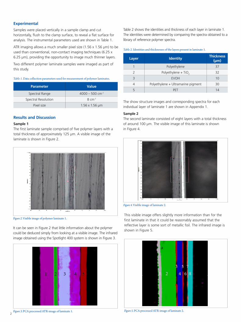
Sample 2The second laminate consisted of eight layers with a total thickness of around 100 μm. The visible image of this laminate is shown in Figure 4.
This visible image offers slightly more information than for the first laminate in that it could be reasonably assumed that the reflective layer is some sort of metallic foil. The infrared image is shown in Figure 5.
Table 2 shows the identities and thickness of each layer in laminate 1. The identities were determined by comparing the spectra obtained to a library of reference polymer spectra.

3
Table 3. Identities and thicknesses of layers in laminate 2.
Layer IdentityThickness
(μm)
1 Polyethylene/Polypropylene Copolymer 6
2 Polypropylene 40
3 Polyurethane 3
4 Polyamide (Nylon) 6 15
5 Polyurethane 2
6 Aluminium 14
7 Polyurethane 3
8 PET 14
Table 3 shows the identies and thicknesses of each layer in laminate 2. This particular sample demonstrates the ability of ATR-Imaging to resolve sections of sample less the 3 μm in thickness.
In each case, the collected spectrum is shown in the same colour as the image, while the reference spectrum is shown in black.
Layer 1 – Polyethylene (37 μm)
Layer 3 – Poly(ethylene vinyl alcohol) (32 μm)
Layer 2 – Polyethylene w/ TiO2 (10 μm)
In this layer, the reference spectrum is that of TiO2, showing the influence the addition of this pigment has on the spectrum.
Layer 4 – Polyethylene w/ ultramarine pigment (30 μm)
In this layer, the reference spectrum is that the ultramarine pigment, showing the influence the addition of this pigment has on the spectrum.
Layer 5 – Polyethylene Terephthalate (14 μm)
Appendix 1
The ‘show structure’ image and corresponding spectrum for each layer of laminate 2 is shown in Appendix 2.
Conclusion
The PerkinElmer Spotlight 400 infrared imaging microscopy with ATR imaging may be used to provide detailed information about the micro-level structure of polymer laminates. SpectrumIMAGE™ software allows the user to perform data analysis with ease in order to unlock valuable information about their samples.
Reference
1. Chanda, M., & Roy, S. K. (2008). Industrial polymers, specialtypolymers, and their applications. London: CRC Press

For a complete listing of our global offices, visit www.perkinelmer.com/ContactUs
Copyright ©2020, PerkinElmer, Inc. All rights reserved. PerkinElmer® is a registered trademark of PerkinElmer, Inc. All other trademarks are the property of their respective owners. 68185 PKI
PerkinElmer, Inc. 940 Winter Street Waltham, MA 02451 USA P: (800) 762-4000 or (+1) 203-925-4602www.perkinelmer.com
Layer 4 – Polyamide 6 (15 μm)
Layer 8 – Polyethylene Terephthalate (14 μm)
Layers 3, 5 and 7 – Polyurethane (3, 2 and 3 μm respectively)
Layer 2 – Polypropylene (40 μm)
Layer 1 – Polyethylene/Polypropylene copolymer (6 μm)
Appendix 2