An iron core probe based inter-laminar core fault detection technique for generator stator cores
2014 Western Protective Relay Conference
64S Protection Guide―Theory, Application and Commissioning of
Generator 100% Stator Ground Fault ProtectionUsing Low Frequency Injection
Steve TurnerSenior Applications Engineer
BECKWITH ELECTRIC COMPANY, INC.
2014 Western Protective Relay Conference
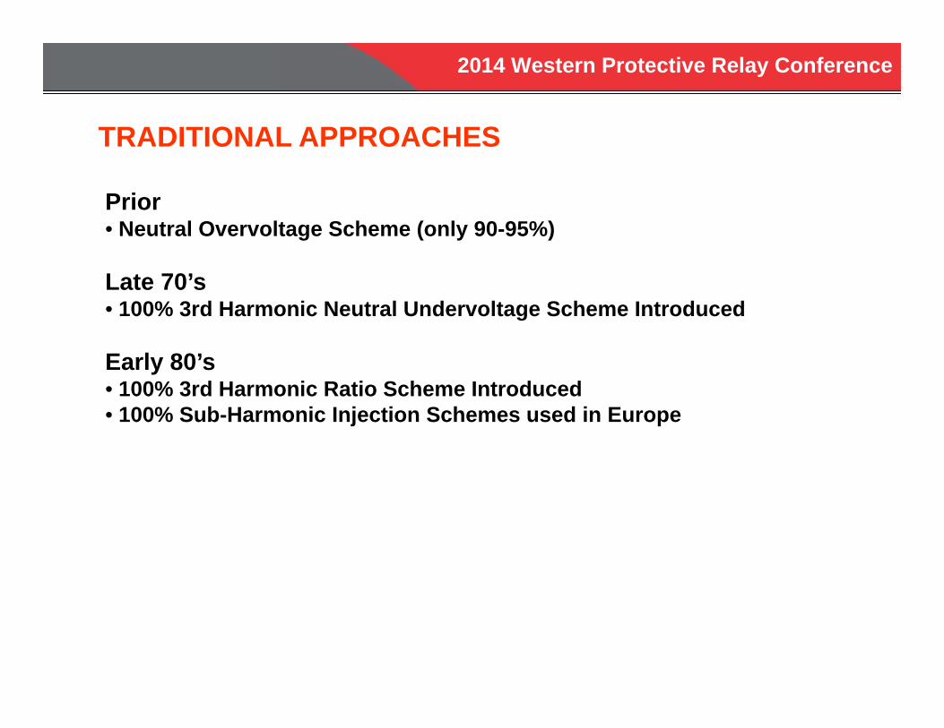
TRADITIONAL APPROACHES
Prior• Neutral Overvoltage Scheme (only 90-95%)
Late 70’s• 100% 3rd Harmonic Neutral Undervoltage Scheme Introduced
Early 80’s• 100% 3rd Harmonic Ratio Scheme Introduced• 100% Sub-Harmonic Injection Schemes used in Europe
2014 Western Protective Relay Conference
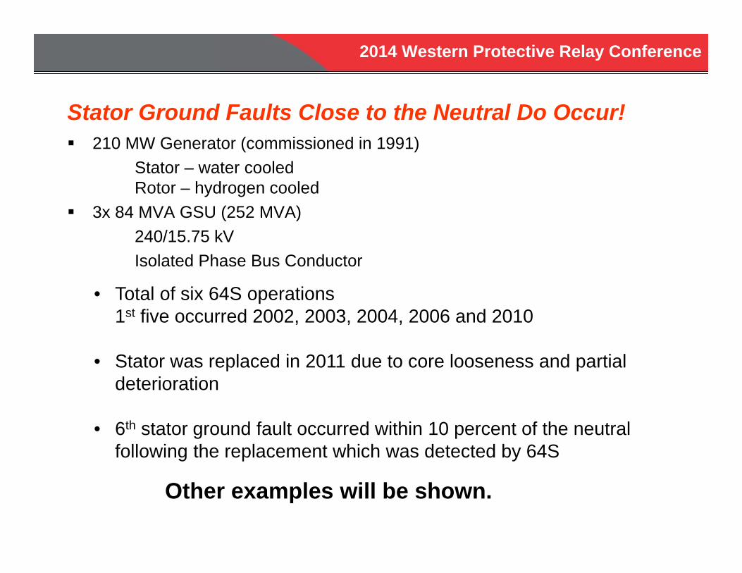
Stator Ground Faults Close to the Neutral Do Occur! 210 MW Generator (commissioned in 1991)
Stator – water cooledRotor – hydrogen cooled
3x 84 MVA GSU (252 MVA)240/15.75 kVIsolated Phase Bus Conductor
• Total of six 64S operations1st five occurred 2002, 2003, 2004, 2006 and 2010
• Stator was replaced in 2011 due to core looseness and partial deterioration
• 6th stator ground fault occurred within 10 percent of the neutral following the replacement which was detected by 64S
Other examples will be shown.
2014 Western Protective Relay Conference
A generator trip will not typically occur if a failure occurs in a lower voltage portion of the winding near the neutral, until some other relay protection detects there is a problem, (e.g., arcing becomes so widespread that other portions of the winding become involved).
There has been recent experience with four such failures in large generators that demonstrate the lack of proper protection can be disastrous.
Each of the four failures caused massive damage to the generator and collectively had a total cost, including repair and loss of generation, close to $500,000,000. This demonstrates that failure of stator windings in the last five percent of the winding is not uncommon.
Catastrophic Damage - Stator Grounds in last 5% of the Winding
2014 Western Protective Relay Conference
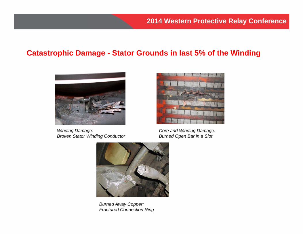
Catastrophic Damage - Stator Grounds in last 5% of the Winding
Winding Damage:Broken Stator Winding Conductor
Core and Winding Damage: Burned Open Bar in a Slot
Burned Away Copper:Fractured Connection Ring

2014 Western Protective Relay Conference
59N Neutral Overvoltage Protection
Fault Position
Volta
ge a
t Neu
tral
(60
Hz)
0% 50% 100%0
0.5pu
1.0pu
N T
2014 Western Protective Relay Conference
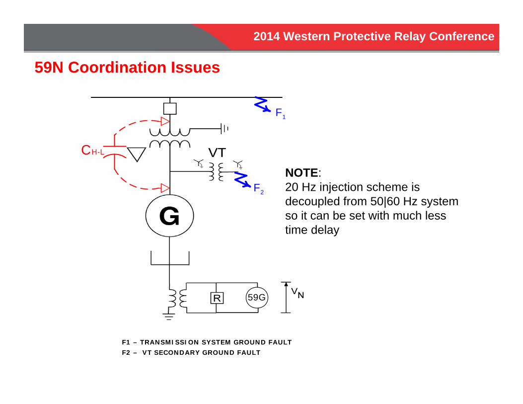
59N Coordination Issues
F1 – TRANSMISSION SYSTEM GROUND FAULTF2 – VT SECONDARY GROUND FAULT
CH-L
F1
F2
59G
NOTE:20 Hz injection scheme is decoupled from 50|60 Hz system so it can be set with much less time delay
2014 Western Protective Relay Conference
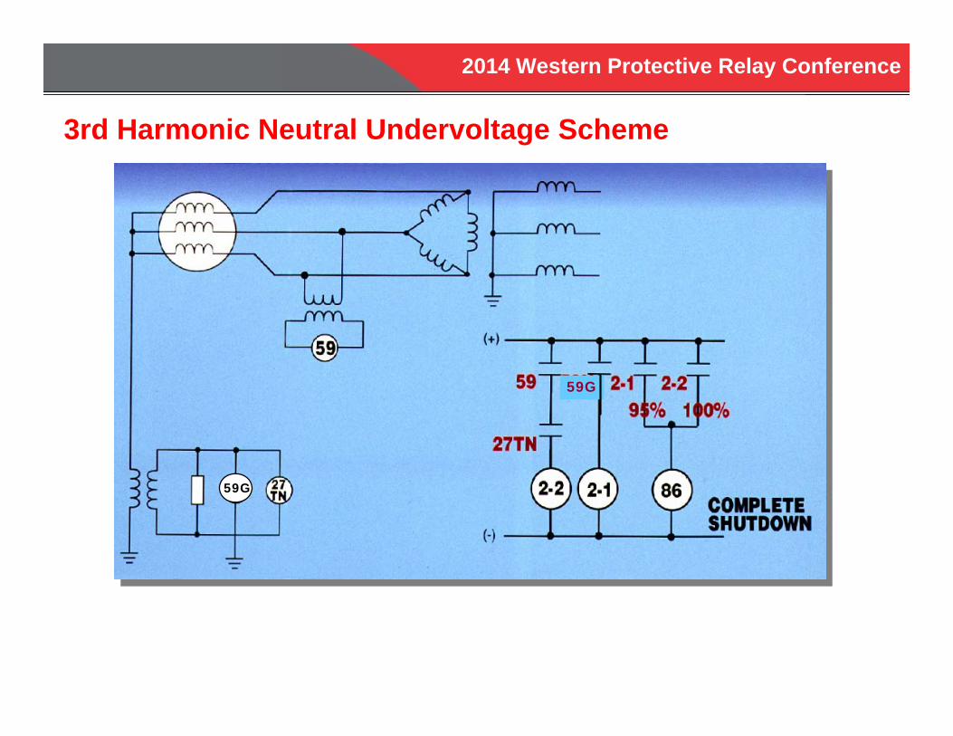
3rd Harmonic Neutral Undervoltage Scheme
59G
59G
2014 Western Protective Relay Conference
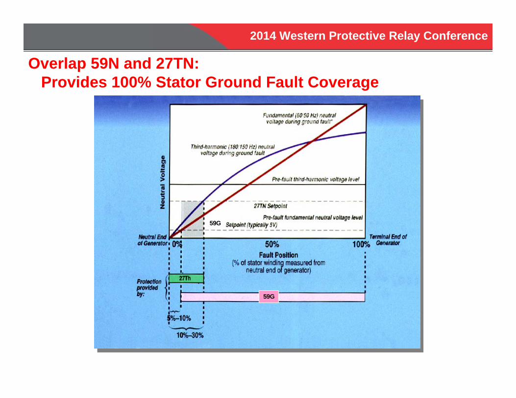
Overlap 59N and 27TN:Provides 100% Stator Ground Fault Coverage
59G
59G
2014 Western Protective Relay Conference
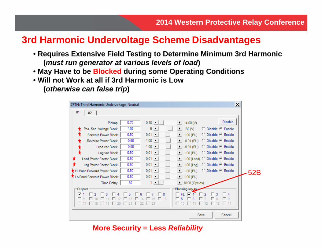
3rd Harmonic Undervoltage Scheme Disadvantages• Requires Extensive Field Testing to Determine Minimum 3rd Harmonic
(must run generator at various levels of load)• May Have to be Blocked during some Operating Conditions• Will not Work at all if 3rd Harmonic is Low
(otherwise can false trip)
52B
More Security = Less Reliability
2014 Western Protective Relay Conference
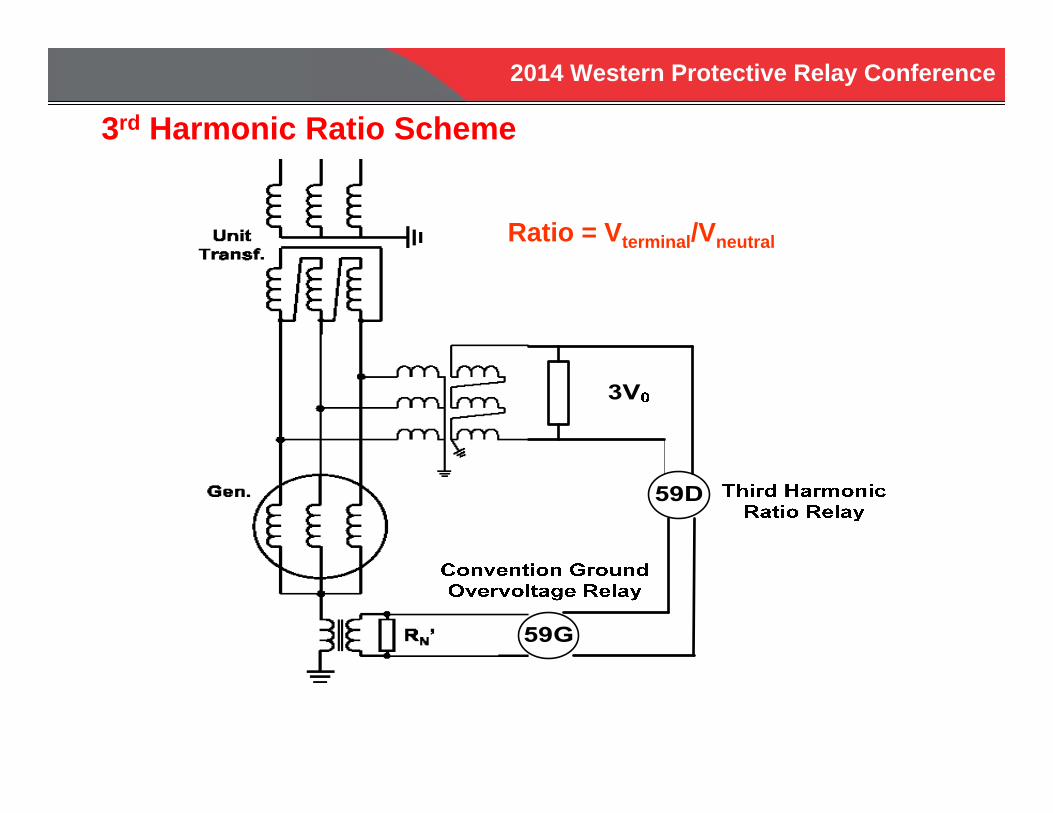
3rd Harmonic Ratio Scheme
Ratio = Vterminal/Vneutral
2014 Western Protective Relay Conference
• Requires Measurement of 3rd Harmonic Terminal Voltage
• Requires Wye Grounded Primary VT with Broken Delta Secondary
• Requires Extensive Field Testing to Determine Maximum 3rd Harmonic Ratio
• Will Not Work at all if 3rd Harmonic is Low (But No False Tripping)
3rd Harmonic Ratio Scheme Disadvantages
2014 Western Protective Relay Conference
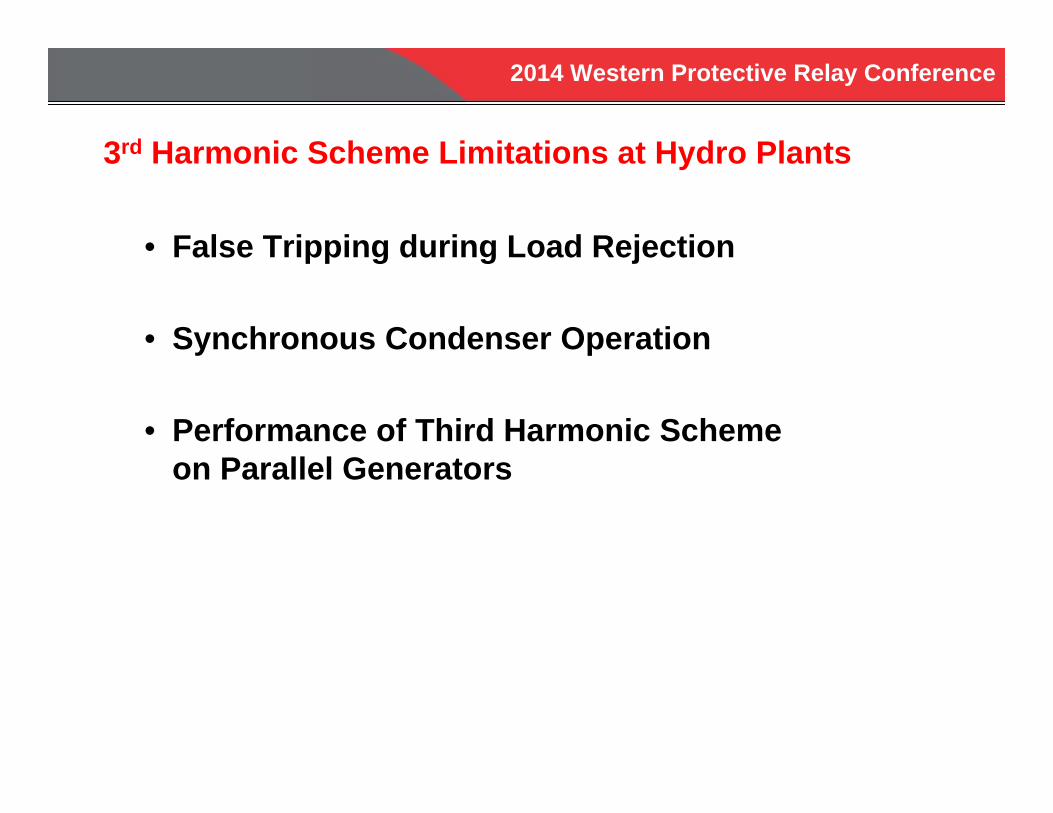
3rd Harmonic Scheme Limitations at Hydro Plants
• False Tripping during Load Rejection
• Synchronous Condenser Operation
• Performance of Third Harmonic Scheme on Parallel Generators
2014 Western Protective Relay Conference
20 Hz SUB-HARMONIC VOLTAGE INJECTION
64S
2014 Western Protective Relay Conference
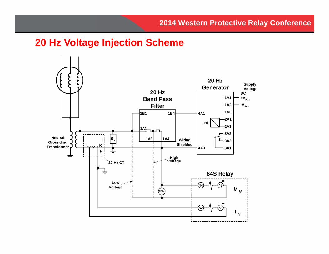
RN
1B1
1A1
1B4
1A3 1A4
20 HzBand Pass
Filter
20 HzGenerator
4A1
1A1
1A2
1A3
2A3
2A1
3A2
3A14A3
Bl
3A3
Supply VoltageDC+VAux
-VAux
44 45
52 53
L Kl k
V N
I N
NeutralGrounding
Transformer
WiringShielded
20 Hz CT
59N
HighVoltage
LowVoltage
64S Relay
20 Hz Voltage Injection Scheme
2014 Western Protective Relay Conference
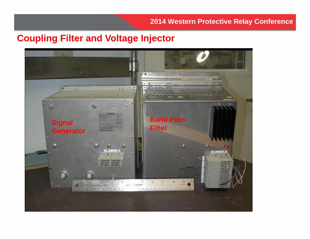
Coupling Filter and Voltage Injector
SignalGenerator
Band PassFilter
2014 Western Protective Relay Conference
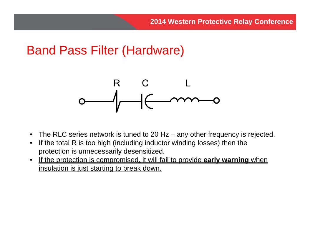
Band Pass Filter (Hardware)
• The RLC series network is tuned to 20 Hz – any other frequency is rejected.• If the total R is too high (including inductor winding losses) then the
protection is unnecessarily desensitized.• If the protection is compromised, it will fail to provide early warning when
insulation is just starting to break down.

2014 Western Protective Relay Conference
High Current Rejection (Hardware)
0.8(240 V) = 192 volts across RN
IN(60 Hz) = (192 V)/(0.125 )/(400/5) = 19.2 amps
N
High current can saturate low current input designed to measure in milli-amps
2014 Western Protective Relay Conference
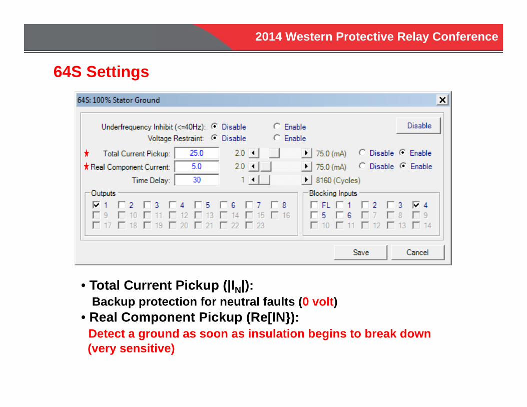
• Total Current Pickup (|IN|):Backup protection for neutral faults (0 volt)
• Real Component Pickup (Re[IN}):Detect a ground as soon as insulation begins to break down(very sensitive)
64S Settings
2014 Western Protective Relay Conference
Commissioning:20 Hz Neutral Current Measurements
Open the High Side GSU Breaker While Testing

2014 Western Protective Relay Conference
Commissioning:Short Circuit at Machine Neutral
RN
V20
RBPF
25V8ohms*80
= 39 mA400:5

2014 Western Protective Relay Conference
Commissioning:Fault Resistance at Machine Neutral
RN
V20
RBPFRF
IN

2014 Western Protective Relay Conference
Calculation of 20 Hz Neutral CurrentNo Fault
VXCP RStator
RFilter = 8 Ohms
RN
CT = 400:5
25 V20 Hz
N
Rstator > 50 kilo-ohms
Primary Secondary
2014 Western Protective Relay Conference
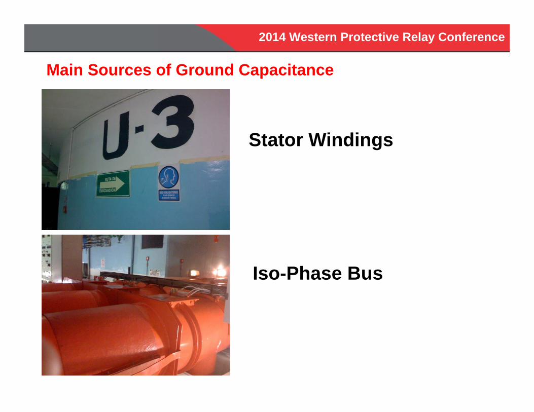
Main Sources of Ground Capacitance
Stator Windings
Iso-Phase Bus
2014 Western Protective Relay Conference
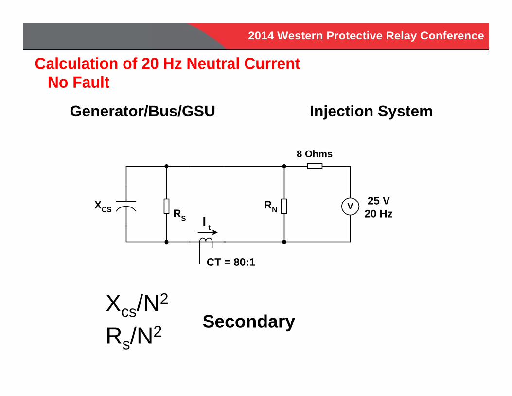
Calculation of 20 Hz Neutral CurrentNo Fault
Xcs/N2
Rs/N2
Generator/Bus/GSU Injection System
Secondary
VXCS RS
8 Ohms
RN
CT = 80:1
25 V20 HzI t
2014 Western Protective Relay Conference
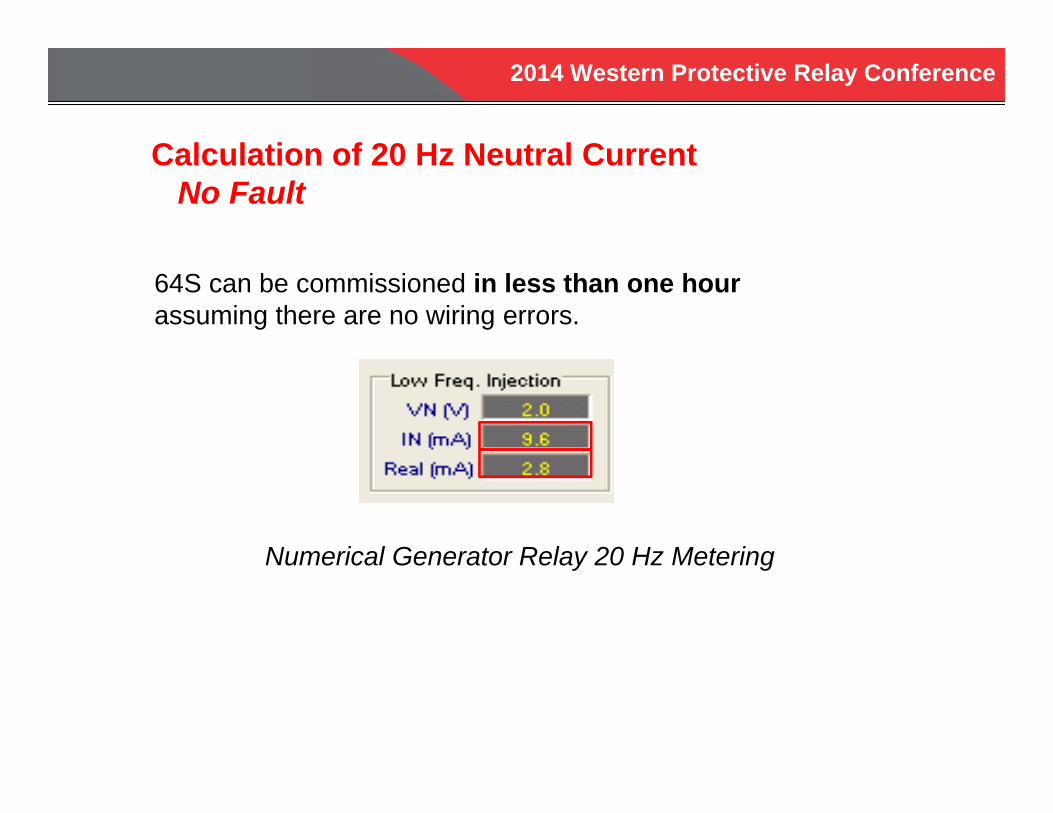
Calculation of 20 Hz Neutral CurrentNo Fault
64S can be commissioned in less than one hourassuming there are no wiring errors.
Numerical Generator Relay 20 Hz Metering
2014 Western Protective Relay Conference
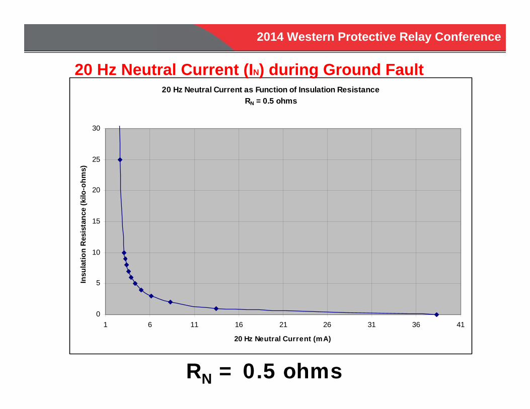
RN = 0.5 ohms
20 Hz Neutral Current as Function of Insulation ResistanceRN = 0.5 ohms
0
5
10
15
20
25
30
1 6 11 16 21 26 31 36 41
20 Hz Neutral Current (mA)
Insu
latio
n R
esis
tanc
e (k
ilo-o
hms)
20 Hz Neutral Current (IN) during Ground Fault
2014 Western Protective Relay Conference
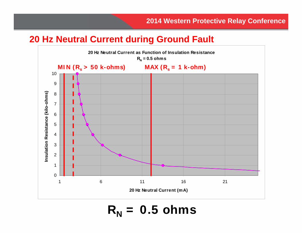
20 Hz Neutral Current as Function of Insulation ResistanceRN = 0.5 ohms
0
1
2
3
4
5
6
7
8
9
10
1 6 11 16 21
20 Hz Neutral Current (mA)
Insu
latio
n R
esis
tanc
e (k
ilo-o
hms)
20 Hz Neutral Current during Ground Fault
RN = 0.5 ohms
MIN (Rs > 50 k-ohms) MAX (Rs = 1 k-ohm)
2014 Western Protective Relay Conference
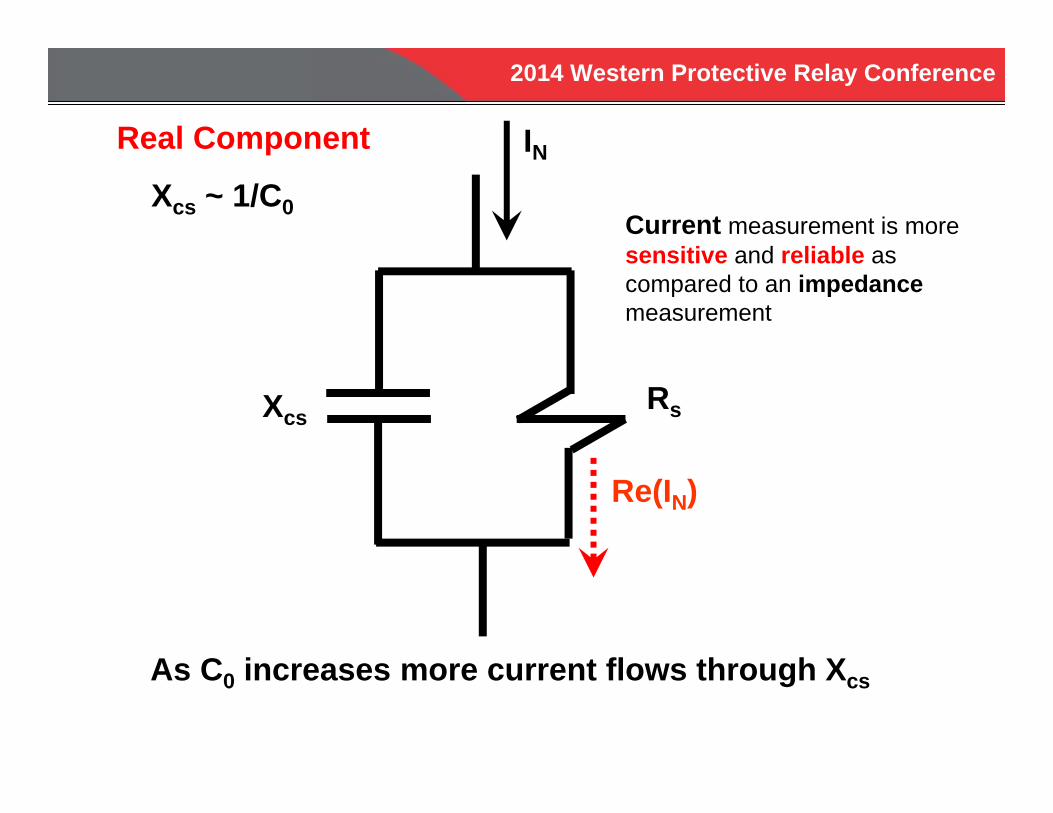
Real Component
Xcs ~ 1/C0
XcsRs
IN
Re(IN)
As C0 increases more current flows through Xcs
Current measurement is more sensitive and reliable as compared to an impedancemeasurement
2014 Western Protective Relay Conference
Pros Does Not Use 3rd Harmonic Voltage
Independent of Generator MW and MVAR Loading
Can Detect Stator Ground Fault When Generator is Off-Line
Detects Stator Ground Faults Over the Entire Winding – No Blind Spots
2014 Western Protective Relay Conference
CONCLUSIONS 100% Stator Ground Fault Protection Prevents Major Damage
(for example, two simultaneous grounds close to neutral) If 3rd Harmonic Schemes are Being Considered
It is Important to First Determine Generator 3rd Harmonic “Signature” (lots of metering data)
3rd Harmonic Schemes Have Many Limitations 20 Hz Injection is Superior 20 Hz Injection Scheme Detects Stator Grounds
Over Entire Stator Winding 20 Hz Injection Scheme Detects Stator Grounds When
Generator is Off-Line
2014 Western Protective Relay Conference
64S Protection Guide―Theory, Application and Commissioning of
Generator 100% Stator Ground Fault ProtectionUsing Low Frequency Injection
Steve TurnerSenior Applications Engineer
BECKWITH ELECTRIC COMPANY, INC.
QUESTIONS?