6300 6310 Treadmill Electronics Repair Manual - SportsArt
97
6300/6310 Treadmill Electronics Repair Manual Version 2; Date: 11-11-04
Transcript of 6300 6310 Treadmill Electronics Repair Manual - SportsArt

6300/6310 Treadmill Electronics Repair Manual
Version 2; Date: 11-11-04

6300/6310 Treadmill Electronics Repair Manual
The 6300/6310 Treadmill Electronics Repair Manual is designed to be a quick, easy troubleshooting guide for technicians in the field. If you have questions or comments, please write to Bob Baumgartner at [email protected]. Version 1 Date: 05-01-03 Version 2 Date: 11-11-04 – Reformatted, corrected, updated for changes to the emergency stop knob and thermal fuse.
00

6300/6310 Treadmill Electronics Repair Manual - Contents
Contents 6300 Introduction – 6300 Treadmill Features 6300 – INTRODUCTION.01 – 6300 Treadmill Specifications at a Glance 6300 – INTRODUCTION.02 – 6300 Treadmill Control Area 6300 – INTRODUCTION.03 – 6300 Display Windows 6300 – INTRODUCTION.04 – 6300 Display Keys 6300 – INTRODUCTION.05 – 6300 Display Unit Feedback LEDs 6300 – INTRODUCTION.06 – Operating the 6300 Treadmill: Start Up 6300 – INTRODUCTION.07 – Operating the 6300 Treadmill: Manual Operation 6300 – INTRODUCTION.08 – Operating the 6300 Treadmill: Stop Functions 6310 Introduction – 6310 Treadmill Features 6310 – INTRODUCTION.01 – 6310 Treadmill Specifications at a Glance 6310 – INTRODUCTION.02 – 6310 Display Windows 6310 – INTRODUCTION.03 – 6310 Display Keys 6310 – INTRODUCTION.04 – 6310 Display Unit Feedback LED 6310 – INTRODUCTION.05 – Operating the 6310 Treadmill: Start Up 6310 – INTRODUCTION.06 – Operating the 6310 Treadmill: Manual Operation 6310 – INTRODUCTION.07 – Operating the 6310 Treadmill: Stop Functions 6310 – INTRODUCTION.08 – Operating the 6310 Treadmill: Programs 6310 – INTRODUCTION.09 – Operating the 6310 Treadmill: KPH/MPH, Distance/Time, Clear
CONTENTS.01

6300/6310 Treadmill Electronics Repair Manual - Contents
Contents (Continued) 6300/6310 Operation – Explains 6300/6310 Operation in General OPERATION.01 – 6300/6310 Power/Signal Diagram OPERATION.02 – 6300/6310 Power/Signal Flow Explanation OPERATION.03 – 6300/6310 Motor Compartment Components 6300/6310 Display – Includes 6300/6310 Display Wiring, LEDs, Test Procedures DISPLAY.01 – 6300/6310 Display Board Wire Connection Diagram DISPLAY.02 – 6300/6310 Display Board Wire Connection Picture DISPLAY.03 – 6300/6310 Display Board LEDs DISPLAY.04 – 6300/6310 Display VCC Circuit Voltage Test DISPLAY.05 – 6300/6310 Display VBB Circuit Voltage Test DISPLAY.06 – 6300/6310 Display Board Main Program IC U5 DISPLAY.07 – 6310 Display Board – Front View 6300/6310 Drive Board – Includes 6300/6310 Drive Board Wiring, LEDs DRIVE BOARD.01 – Drive Board Wire Connection Diagram DRIVE BOARD.02 – 6300/6310 Drive Board Wire Connection Picture DRIVE BOARD.03 – 6300/6310 Drive Board LEDs – Normally Lit DRIVE BOARD.04 – 6300/6310 Drive Board LEDs – Normally Not Lit DRIVE BOARD.05 – 6300/6310 Drive Board Picture
CONTENTS.02

6300/6310 Treadmill Electronics Repair Manual - Contents
Contents (Continued) 6300/6310 Drive Motor System Operation MOTOR.01 – 6300/6310 Motor System Operation MOTOR.02 – 6300/6310 Voltage to Motor – Test Configuration MOTOR.03 – 6300/6310 Voltage to Motor – Test Procedure, Test Results MOTOR.04 – 6300/6310 Motor Circuit and OHM Test Configuration, Procedure MOTOR.05 – 6300/6310 Transformer Test Configuration MOTOR.06 – 6300/6310 Transformer Test Procedure, Results MOTOR.07 – 6300/6310 Inductor Test Configuration, Procedure MOTOR.08 – 6300/6310 Optic Sensor Signal Test MOTOR.09 – 6300/6310 Optic Sensor Signal Test Procedure, Results 6300/6310 Incline System Operation INCLINE.01 – 6300/6310 Incline System Operation INCLINE.02 – 6300/6310 Voltage to Incline Motor – Test Configuration INCLINE.03 – 6300/6310 Voltage to Incline Test Procedure, Results INCLINE.04 – 6300/6310 Incline VR Voltage –Test Configuration INCLINE.05 – 6300/6310 Incline VR Voltage Test Procedure, Results 6300/6310 Incline Calibration CALIBRATION.01 – 6300/6310 Incline Calibration Overview CALIBRATION.02 – Mechanical Calibration CALIBRATION.03 – Electronic Calibration CALIBRATION.04 – Incline Calibration Testing
CONTENTS.03

6300/6310 Treadmill Electronics Repair Manual - Contents
Contents (Continued)
6300/6310 Heart Rate System HR.01 – Heart Touch Rate (HTR) Operation HR.02 – POLAR Heart Rate (HR) Operation HR.03 – HTR Board LED Operation, LED Indicator Definitions HR.04 – Possible Malfunctions, Troubleshooting HR.05 – HTR Cable/Handlebar Test Procedure 6300/6310 Troubleshooting ERR1.01 – ERR 1 – Motor Movement ERR1.02 – Troubleshooting: ERR1 Motor Movement ERR1.03 – ERR 1 – No Motor Movement ERR1.04 – Troubleshooting: ERR1 Motor Movement ERR3.01 – ERR 3 ERR3.02 – ERR 3 Troubleshooting ERR7.01 – ERR7 ERR7.02 – ERR7 Troubleshooting NO DISPLAY.01 – Display Does Not Light NO DISPLAY.02 – Troubleshooting: Display Does Not Light
CONTENTS.04

6300/6310 Treadmill Electronics Repair Manual - Contents
Contents (Continued) Testing Components Unique to 6300/6310 Treadmills FILTER.01 – EMI Filter FILTER.02 – EMI Filter Test THERMAL FUSE.01 – Thermal Fuse Placement THERMAL FUSE.02 – Thermal Fuse Operation THERMAL FUSE.03 – Thermal Fuse Troubleshooting EMERGENCY STOP.01 – Emergency Stop Signal Diagram, Emergency Stop Knob Operation EMERGENCY STOP.02 – Emergency Stop Knob Troubleshooting, Emergency Stop Knob Test Configuration EMERGENCY STOP.03 – Emergency Stop Revision KEYS.01 – Key Operation, Key Test Configuration KEYS.02 – Key Test Procedure Reference REF.01 – 6300/6310 Drive Board LED Reference Chart REF.02 – 6300/6310 Display LED Reference Chart, 6300/6310 Fuse Reference Chart REF.03 – VR Voltages for Various SportsArt Treadmill DC Incline Motors
CONTENTS.05

6300/6310 Treadmill Electronics Repair Manual – 6300 Introduction
6300 Introduction – 6300 Treadmill Features 6300 – INTRODUCTION.01 – 6300 Model Treadmill Specifications at a Glance 6300 – INTRODUCTION.02 – 6300 Treadmill Control Area 6300 – INTRODUCTION.03 – 6300 Display Windows 6300 – INTRODUCTION.04 – 6300 Display Keys 6300 – INTRODUCTION.05 – 6300 Display Unit Feedback LEDs 6300 – INTRODUCTION.06 – Operating the 6300 Treadmill: Start Up 6300 – INTRODUCTION.07 – Operating the 6300 Treadmill: Manual Operation 6300 – INTRODUCTION.08 – Operating the 6300 Treadmill: Stop Functions
6300 INTRO.00

6300/6310 Treadmill Electronics Repair Manual – 6300 Introduction
6300 Treadmill Specifications at a Glance
Function Description Operation Modes Originally had only manual mode and no exercise programs. Exercise programs added July
2003. Program time added Jan. 2004 Heart Rate (HR) Function POLAR transmitter and heart touch rate (HTR) readings Heart Rate Control (HRC) Heart rate target values: 65%; 72.5%; 80%, Sept. 2003
Display – 7-Segment Digital
1.Distance / Incline (Board revised Feb. 2003 because incline stuck.) 2.Calories / HR 3.Time / Pace 4.Speed / Mets (Display became C-Safe compatible Dec. 2004)
Display - Keypad PET touch type, Sept. 2003 Emergency Stop Emergency stop knob on display (removed Sept. 2004); pause/stop key on keypad Drive Board Revised June 2004 (new is V3.2) after motor brush change Motor Speed 0.1-12.0 MPH (North America standard); 0.2-20.0 KPH (Europe) Motor Highest Speed 2900 RPM Motor Horse Power Originally 3.2 HP; revised to 4.0 Sept. 2003 with ribbed exterior Motor Thermal Switch Turns on “Service” indicator if motor gets too hot, Sept. 2003 Incline Range 0-15% Incline VR Calibration 0% position = 1.20 VDC; measured on VR blue and green wires MPH in N. America KPH in Europe
MPH determined by the IC chip. MPH =N. American standard; KPH=European standard. Distance units cannot be changed by touching keys
Power Requirements 120 VAC, 20 AMP dedicated Frame Incline support added Nov. 2003; Color: Originally gray, became silver Nov. 2004
6300 INTRO.01

6300/6310 Treadmill Electronics Repair Manual – 6300 Introduction
6300 Treadmill Control Area
6300 INTRO.02
Keypad
Display
HTR Grip (left)
Emergency Stop Knob (prior to Sept. 2004)
HTR Grip (right)
Note: Picture shows old type HTR grips. As of Sept. 2004, HTR grips had two, rather than four, contact plates.

6300/6310 Treadmill Electronics Repair Manual – 6300 Introduction
6300 Display Windows
6300 INTRO.03
65% Target Heart Rate Window Shows 65% target heart rate
72.5% Target Heart Rate Window Shows 72.5% target heart
DISTANCE & INCLINE Window DISTANCE: Shows distance
when indicator is lit INLCINE: Shows incline
position when indicator is lit
CALORIES & CAL/HR Window CALORIES: Shows calorie
expenditure when indicator is lit. CAL/HR: Shows calorie
expenditure per hour when indicator is lit.
TIME & PACE Window TIME: Shows duration of
exercise time when indicator is lit.
PACE: Shows minutes per mile when indicator is lit.
HEART RATE Window Shows actual heart rate
80% Target Heart Rate Window Shows 80% target heart rate
SPEED & METS Window SPEED: Shows treadmill
speed when indicator is lit. METS: Shows Metabolic
Equivalency Table (METS) when indicator is lit.

6300/6310 Treadmill Electronics Repair Manual – 6300 Introduction
6300 Display Keys
6300 INTRO.04
<CHANGE> Key Press to change modes: Distance/Incline;
Calories/Cal/Hr; Time/Pace; Speed/METS
INCLINE<▲>/<▼> Key
Press INCLINE <▲> to
increase incline. Press <▼> to decrease incline.
<ENTER> Key Press to confirm your choice.
SPEED<▲>/<▼> Keys
Press <▲> to increase or <▼> to decrease unit speed.
EMERGENCY STOP KnobPress to stop in an
emergency. Twist to reset. Workout settings will be cleared. (Prior to Sept. 2004)
STOP Key Press to stop the unit. Press
again to restart the unit. Workout memory will be retained.

6300/6310 Treadmill Electronics Repair Manual – 6300 Introduction
6300 Display Unit Feedback LEDs
6300 INTRO.05
Note: This picture shows an old display without exercise programs. Programs were added May 2004.
Motor Overheat LED Lights to indicate that the motor is too hot.
Inspect the motor.

6300/6310 Treadmill Electronics Repair Manual – 6300 Introduction
Operating the 6300 Treadmill: Start Up Quick Start: Turn on the On/Off switch. On/Off Switch LED lights up. Display lights up. “6300” scrolls across the lower windows. Press Speed <▲> key. Start with Personalized Settings 1. Start Up: Turn on the On/Off switch. On/Off Switch LED lights up. Display lights up. “6300” scrolls across the lower windows. Press any key except Speed <▲> key.
2. Age Setting: Age LED lights up. A number appears in the distance/incline window. Press incline <▲> or <▼> key to change the age setting. Press ENTER key to confirm your choice. 3. Weight Setting: Weight LED lights up. A number appears in the distance/incline window. Press incline <▲> or <▼> key to change the weight setting. Press ENTER to confirm your choice.
6300 INTRO.06
6300/6310 Treadmill Electronics Repair Manual – 6300 Introduction
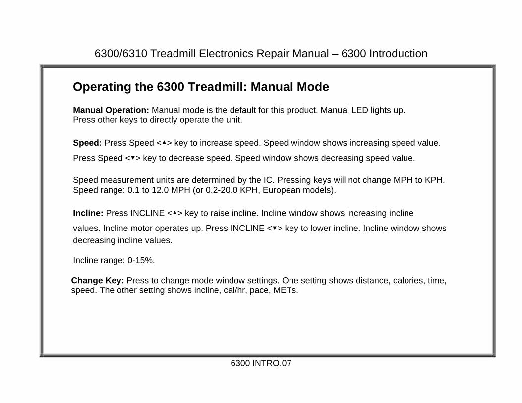
Operating the 6300 Treadmill: Manual Mode
Manual Operation: Manual mode is the default for this product. Manual LED lights up. Press other keys to directly operate the unit. Speed: Press Speed <▲> key to increase speed. Speed window shows increasing speed value.
Press Speed <▼> key to decrease speed. Speed window shows decreasing speed value. Speed measurement units are determined by the IC. Pressing keys will not change MPH to KPH. Speed range: 0.1 to 12.0 MPH (or 0.2-20.0 KPH, European models). Incline: Press INCLINE <▲> key to raise incline. Incline window shows increasing incline
values. Incline motor operates up. Press INCLINE <▼> key to lower incline. Incline window shows decreasing incline values. Incline range: 0-15%.
Change Key: Press to change mode window settings. One setting shows distance, calories, time, speed. The other setting shows incline, cal/hr, pace, METs.
6300 INTRO.07

6300/6310 Treadmill Electronics Repair Manual – 6300 Introduction
Operating the 6300 Treadmill: Stop Functions
STOP/PAUSE Key Pause function: Press the STOP/Pause key once. Display beeps once. Values such as calories remain on display. SPEED/METS window flashes “0.0”. Press speed up to resume your workout. Display beeps once. Values such as calories are retained. Clear function: Hold the STOP/Pause key for three seconds. Display beeps once. All values clear. Unit reverts to start up mode. “6300” scrolls across the lower windows.
EMERGENCY STOP Knob Emergency Stop Function: Press the emergency stop knob. Display beeps once. Emergency stop indicator lights. Lower window shows “----”. Reset Function: Rotate the emergency stop knob clockwise. Display beeps once. Emergency stop indicator extinguishes. Unit reverts to start up mode. “6300” scrolls across the lower windows. Note: The emergency stop knob was eliminated Sept. 2004. To update an old unit, eliminating the stop knob, you need two things: A jumper, which goes into the stop knob wire connector on the display, and a plastic sticker, which covers the hole where the stop knob sat.
6300 INTRO.08

6300/6310 Treadmill Electronics Repair Manual – 6310 Introduction
6310 Introduction – 6310 Treadmill Features 6310 – INTRODUCTION.01 – 6310 Treadmill Specifications at a Glance 6310 – INTRODUCTION.02 – 6310 Display Windows 6310 – INTRODUCTION.03 – 6310 Display Keys 6310 – INTRODUCTION.04 – 6310 Display Unit Feedback LED 6310 – INTRODUCTION.05 – Operating the 6310 Treadmill: Start Up 6310 – INTRODUCTION.06 – Operating the 6310 Treadmill: Manual Operation 6310 – INTRODUCTION.07 – Operating the 6310 Treadmill: Stop Functions 6310 – INTRODUCTION.08 – Operating the 6310 Treadmill: Programs 6310 – INTRODUCTION.09 – Operating the 6310 Treadmill: KPH/MPH, Distance/Time, Clear
6310 INTRO.00

6300/6310 Treadmill Electronics Repair Manual – 6310 Introduction
6310 Treadmill Specifications at a Glance Function Description Operation Modes Manual; Programs: college track, climber’s trek, bay run, river run; Interval 1:1; Interval 1:2.
Programs originally had a set 30-minute length; Time settings were added Jan. 2004. Heart Rate (HR) Function POLAR transmitter and heart touch rate (HTR) Heart Rate Control (HRC) Heart rate target values: 65%; 72.5%; 80% Display – Dot Matrix 30 x 16 dot
Display - Digital Windows
1.Distance / Incline (Board revised Feb. 2003 because incline stuck.) 2.Calories / HR 3.Time / Pace 4.Speed / Mets (Display became C-Safe compatible Dec. 2004)
Display - Keypad PET touch type, Sept. 2003 Emergency Stop Emergency stop knob on display (removed Sept. 2004); pause/stop key on keypad Drive Board Revised June 2004 (new is V3.2) after motor brush change Motor Speed 0.1-12.0 MPH (North America standard); 0.2-20.0 KPH (Europe) Motor Highest Speed 2900 RPM Motor Horse Power Originally 3.2 HP; revised to 4.0 Sept. 2003 with ribbed exterior Motor Thermal Switch Turns on “Service” indicator if motor gets too hot (Sept. 2003) Incline Range 0-15% Incline VR Calibration 0% position = 1.20 VDC; measured on VR blue and green wires Units: MPH/KPH Can be set by key sequence: See 6310 INTRO.08. Power Requirements 120 VAC, 20 AMP dedicated (Europe: 220 VAC) Frame Color: Originally gray, became silver Nov. 2004
6310 INTRO.01

6300/6310 Treadmill Electronics Repair Manual – 6310 Introduction
6310 Display Windows
6310 INTRO.02
65% Target Heart Rate Window Shows 65% target heart rate
80% Target Heart Rate Window Shows 80% target heart rate
DISTANCE & INCLINE Window DISTANCE: Shows distance
when indicator is lit. INCLINE: Shows incline
position when indicator is lit.
CALORIES & CAL/HR Window CALORIES: Shows calorie expenditure when indicator is lit. CAL/HR: Shows calories per hour when indicator is lit.
Dot Matrix “Main” Window Shows scrolling messages
TIME & PACE Window TIME: Shows duration of exercise time when indicator is lit. PACE: Shows minutes per mile or kilometer when indicator is lit.
HEART RATE Window Shows actual heart rate
SPEED & METS Window SPEED: Shows speed when indicator is lit. METS: Shows Metabolic Equivalency Table (METS) when
72.5% Target Heart Rate Window Shows 72.5% target heart rate
6300/6310 Treadmill Electronics Repair Manual – 6310 Introduction
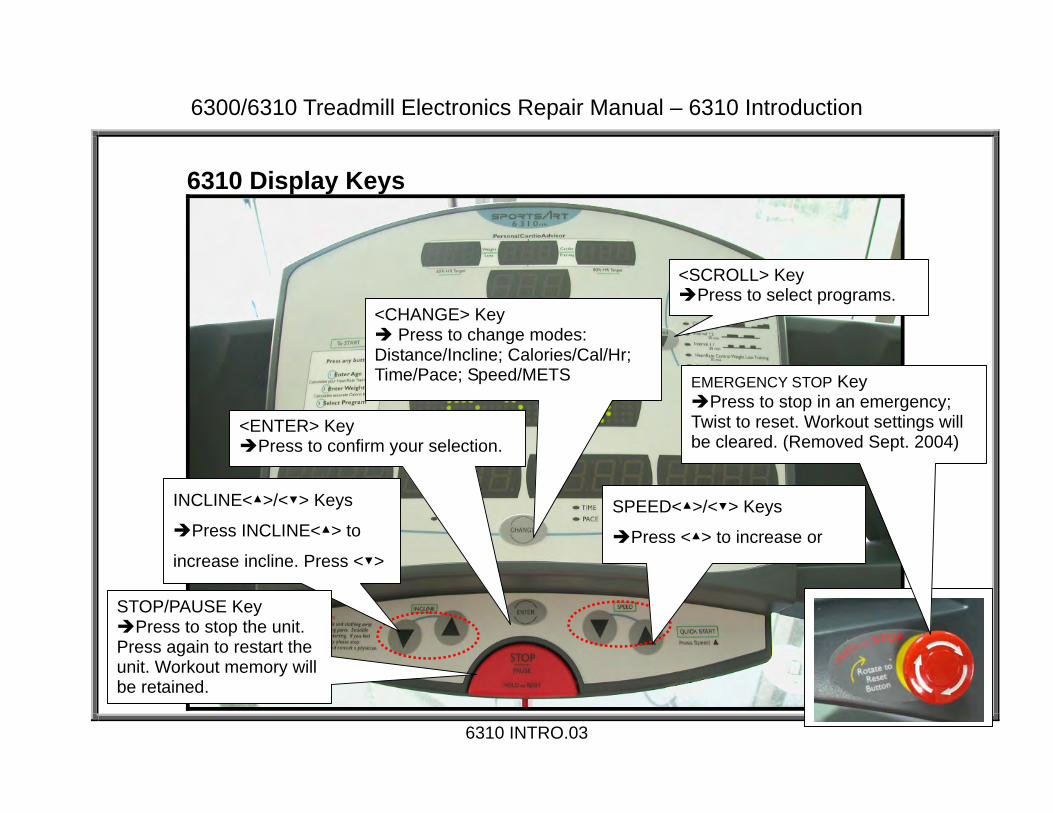
6310 Display Keys
6310 INTRO.03
<SCROLL> Key Press to select programs.
<CHANGE> Key Press to change modes:
Distance/Incline; Calories/Cal/Hr; Time/Pace; Speed/METS
INCLINE<▲>/<▼> Keys
Press INCLINE<▲> to
increase incline. Press <▼>
<ENTER> Key Press to confirm your selection.
SPEED<▲>/<▼> Keys
Press <▲> to increase or
EMERGENCY STOP Key Press to stop in an emergency;
Twist to reset. Workout settings will be cleared. (Removed Sept. 2004)
STOP/PAUSE Key Press to stop the unit.
Press again to restart the unit. Workout memory will be retained.

6300/6310 Treadmill Electronics Repair Manual – 6310 Introduction
6310 Display Unit Feedback LED
6310 INTRO.04
Motor Overheat LED Lights to indicate that the motor is
too hot. Inspect the motor. Note: This shows the old, 30-minute exercise programs in units before Jan. 2004.

6300/6310 Treadmill Electronics Repair Manual – 6310 Introduction
Operating the 6310 Treadmill: Start Up Quick Start: Turn on the On/Off switch. On/Off Switch LED lights up. Display lights up. “SPORTSART” scrolls across the top of the main window. “6310” appears in the lower part of the main window. Press SPEED <▲> key. Start Up with Personalized Settings 1. Start Up: Turn on the On/Off switch. On/Off Switch LED lights up. Display lights up. “SPORTSART” scrolls across the top of the main window. “6310” appears in the lower part of the main window. Press any key except SPEED up.
2. Age Setting: Age LED lights. “PRESS INCLINE ▲▼ TO INPUT YOUR AGE, PRESS ENTER…” scrolls across the top of the main window. “AGE” appears in the lower part of the main window. Press incline <▲> or <▼> key to set age. Press ENTER key to confirm your choice. 3. Weight Setting: Weight LED lights. “PRESS INCLINE TO INPUT YOUR WEIGHT, PRESS ENTER…” scrolls across the top of the main window. “LB” or “KG” appears in the lower part of the main window. A number appears in the distance/incline window. Press incline <▲> or <▼> key to change the weight setting. Press ENTER key to confirm your choice. 4. Manual Operation: “PRESS SPEED <▲>” scrolls across the main window. The SPEED LED lights. “0.0” flashes in the SPEED/METS window. In the program area, the MANUAL indicator lights. Press SPEED<▲> key. Treadmill walk belt starts moving.
6310 INTRO.05

6300/6310 Treadmill Electronics Repair Manual – 6310 Introduction
Operating the 6310 Treadmill: Manual Operation To enter manual mode, press the SCROLL key until the MANUAL indicator lights. Manual mode provides direct control over speed, incline, and other functions. Speed: Press Speed <▲> key to increase speed. Speed window shows increasing speed value.
Press Speed <▼> key to decrease speed. Speed window shows decreasing speed value. Speed measurement units are determined by the IC. Pressing keys will not change MPH to KPH. Speed range: 0.1 to 12.0 MPH (or 0.2-20.0 KPH, European models). Incline: Press INCLINE <▲> key to raise incline. Incline window shows increasing incline
values. Incline motor operates up. Press INCLINE <▼> key to lower incline. Incline window shows decreasing incline values. Incline range: 0-15%.
Change Key: Press to change mode window settings. One setting shows distance, calories, time, speed. The other setting shows incline, cal/hr, pace, METs.
6310 INTRO.06

6300/6310 Treadmill Electronics Repair Manual – 6310 Introduction
Operating the 6310 Treadmill: Stop Functions
STOP/PAUSE Key Pause function: Press the STOP/Pause key once. Display beeps once. Workout memory values, such as calorie expenditure, remain on display. SPEED indicator lights. SPEED/METS window flashes “0.0”. Press speed up to resume your workout. Display beeps once. Workout memory, including calorie expenditure, etc., is retained. Clear function: Hold the STOP/Pause key for three seconds. Display beeps once. All values clear. Unit reverts to start up mode. “SPORTSART” scrolls across the upper part of the main window. “6310” appears in the lower part of the main window.
Emergency Stop Knob Emergency Stop Function: Press the emergency stop knob. Display beeps once. All values clear. All functions stop. “RESET EMERGENCY STOP BUTTON” scrolls across main window. Reset Function: Rotate the emergency stop knob clockwise. Display beeps once. Unit reverts to start up mode. “SPORTSART” scrolls across the upper part of the main window. “6310” appears in the lower part of the main window. Note: The emergency stop knob was eliminated Sept. 2004. To update an old unit, eliminating the stop knob, you need two things: A jumper, which goes into the stop knob wire connector on the display, and a plastic sticker, which covers the hole where the stop knob sat.
6310 INTRO.07
6300/6310 Treadmill Electronics Repair Manual – 6310 Introduction
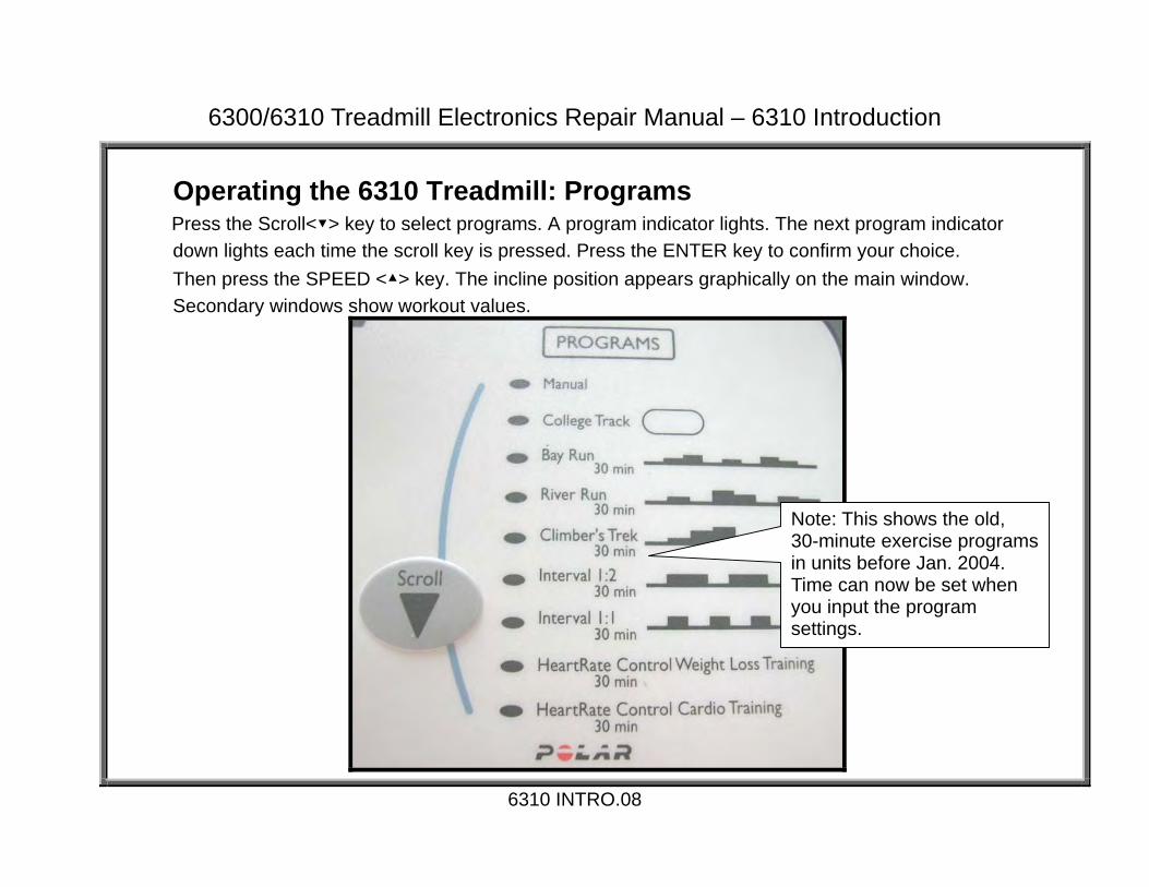
Operating the 6310 Treadmill: Programs
Press the Scroll<▼> key to select programs. A program indicator lights. The next program indicator down lights each time the scroll key is pressed. Press the ENTER key to confirm your choice. Then press the SPEED <▲> key. The incline position appears graphically on the main window. Secondary windows show workout values.
6310 INTRO.08
Note: This shows the old, 30-minute exercise programs in units before Jan. 2004. Time can now be set when you input the program settings.

6300/6310 Treadmill Electronics Repair Manual – 6310 Introduction
KPH/MPH, Distance/Time, Clear Set MPH/KPH: Turn on the unit. “SPORTSART” scrolls across the main window. “6310” appears in the lower part of the main window. Hold the CHANGE key down three seconds. “PRESS TO SELECT MPH/KPH, PRESS ENTER” scrolls across the top part of the main window. “MPH” or “KPH” appears on the lower part of the main window. Press <▲> and
<▼> keys to toggle between MPH and KPH. When your choice appears, press the ENTER key to confirm your selection.
See Distance/Time: “PRESS ▲▼ TO SELECT MODIFY HRC TARGET HR (Y/N)?, PRESS ENTER” scrolls across
the top part of the main window. “NO” or “YES” appears on the lower part of the main window. Press <▲> and <▼> keys to toggle between “no” and “yes”. Select your choice. Press ENTER key to continue.
Distance: A four-digit number appears over the word “MILE” (KM if in metric mode). “TOTAL DISTANCE” scrolls across the main window. This is the distance of unit operation. Press ENTER key to continue.
Time: A four-digit number appears over the word HOUR. “TOTAL TIME” scrolls across the main window. This is the total time of unit operation. Press ENTER key to continue.
Start Up: Unit enters start up mode. “SPORTSART” scrolls across the top part of the main window. “6310” appears in the lower part of the main window.
To Clear Time/Distance: In start up mode, press STOP/PAUSE and ENTER keys for one second. “PRESS ▲▼ TO SELECT CLEAR TOTAL DISTANCE & TIME (Y/N)?, PRESS ENTER” scrolls across the top of the main screen. “NO” or “YES” appears on the bottom of the main screen. Press <▲> <▼> keys to select “YES” to delete the time and distance or select “NO” to preserve the present distance/time memory. Press ENTER key to confirm your choice.
6310 INTRO.09

6300/6310 Treadmill Electronics Repair Manual - Operation
6300/6310 Operation – Explains 6300/6310 Operation in General OPERATION.01 – 6300/6310 Power/Signal Diagram OPERATION.02 – 6300/6310 Power/Signal Flow Explanation OPERATION.03 – 6300/6310 Motor Compartment Components
OPERATION.00
6300/6310 Treadmill Electronics Repair Manual – Operation
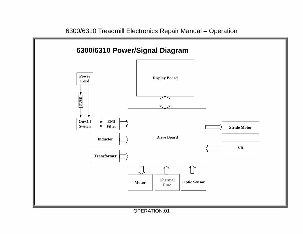
6300/6310 Power/Signal Diagram
Display Board
Drive Board
VR
Stride Motor
Motor Optic Sensor
Inductor
FUSE
EMIFilter
On/OffSwitch
ThermalFuse
Transformer
PowerCord
OPERATION.01

6300/6310 Treadmill Electronics Repair Manual – Operation
6300/6310 Power/Signal Flow Explanation 1. AC voltage travels through the power cord, fuse, on/off switch, EMI filter, into the drive board. 2. AC voltage travels from the drive board to the transformer. The transformer outputs lower levels of AC voltage. 3. The drive board processes the AC voltage into DC voltage for use by the display, drive motor, and incline motor. 4. When the user presses a key, a signal travels from the keypad to the main program in the display, where it is processed. 5. The display board sends a command via the ribbon cable to the drive board. 6. The drive board provides DC voltage to motors as directed by the display. For example, when you press the Speed Up key, the signal travels from the display to the drive board via the ribbon cable; the drive board emits voltage for drive motor operation. Similarly, when you press the Incline Up key, the drive board emits voltage for incline motor operation. 7. On both the drive motor and incline motor are sensors which tell the display about motor operation. Their signals travel to the drive board, up the ribbon cable, to the display. 8. On the drive motor is an optic sensor. As the drive motor rotates, the optic sensor wheel rotates. The sensor detects the difference between optic wheel teeth and spaces, thus indicating speed. 9. On the incline motor is a variable resistor (VR). As the incline motor turns, the VR turns, and its output voltage changes, thus indicating the incline position. 10. The display uses sensor signals to determine whether to command the drive board to continue providing or shut off power to the motors. The Role of Other Parts 1. The inductor ensures steady current to the drive motor. 2. The thermal fuse on the drive motor is activated if the motor becomes too hot. When the thermal fuse is activated (the circuit stops conducting), the “service required” indicator on the display lights. 3. The Electro Magnetic Irradiation (EMI) filter prevents interference to other products.
OPERATION.02

6300/6310 Treadmill Electronics Repair Manual – Operation
6300/6310 Motor Compartment Components
OPERATION.03
EMI Filter Drive Motor Note: Old drive motor is shown. New ones have ribs for heat dissipation. Change occurred Sept. 2003.
Optic Sensor Board
Optic Sensor Wheel
Incline VR C
Incline Motor
Drive Board
Transformer
Inductor (not shown)

6300/6310 Treadmill Electronics Repair Manual – Display
Display – Includes 6300/6310 Display Wiring, LEDs, Test Procedures DISPLAY.01 – 6300/6310 Display Board Wire Connection Diagram DISPLAY.02 – 6300/6310 Display Board Wire Connection Picture DISPLAY.03 – 6300/6310 Display Board LEDs DISPLAY.04 – 6300/6310 Display VCC Circuit Voltage Test DISPLAY.05 – 6300/6310 Display VBB Circuit Voltage Test DISPLAY.06 – Display Board Main Program IC U5 DISPLAY.07 – 6310 Display Board – Front View
DISPLAY.00

6300/6310 Treadmill Electronics Repair Manual – Display
6300/6310 Display Board Wire Connection Diagram
Display Board
C-SAFEBoardHTR
Board
Keypad
EmergencyStop Knob
CARDIOAccessory
Board
POLARReceiver
HTR Handlebar(Left, Right)
Drive Board
DISPLAY.01

6300/6310 Treadmill Electronics Repair Manual – Display
6300/6310 Display Board Wire Connection Picture
DISPLAY.02
CON1 Main “Ribbon” Cable
To Drive Board
CON6 To Keypad
CON4,CON5 接至 CSAFE 小板
CON7 To CARDIO Board
CON3 To Heart Touch
Rate Board
CON4, CON5 To C-SAFE Board
CON8 To Emergency Stop Knob
Note: A black jumper is placed here on units without the stop knob.

6300/6310 Treadmill Electronics Repair Manual – Display
6300/6310 Display Board LEDs
DISPLAY.03
LED21 POWER Indicator Lit: Power is supplied for display
operation.
LED20 C-SAFE Indicator Lit: Power is supplied for
C-SAFE operation.

6300/6310 Treadmill Electronics Repair Manual – Display
6300/6310 Display VCC Circuit Voltage Test
DISPLAY.04
LED21 Display Power Indicator and Capacitor C26
Test Procedure 1. Inspect whether LED21, the VCC circuit voltage indicator, lights. LED21 lights when the display has voltage from the drive board. 2. Place probes as shown on the pins of capacitor C26. Normal reading: 5 VDC. If so, the display has power to operate.

6300/6310 Treadmill Electronics Repair Manual – Display
6300/6310 Display VBB Circuit Voltage Test
DISPLAY.05
Test Procedure: Place probes as shown on the pins of capacitor C41. Normal reading: 14 VDC.

6300/6310 Treadmill Electronics Repair Manual – Display
Display Board Main Program IC U5
DISPLAY.06
Program IC U5
6300/6310 Treadmill Electronics Repair Manual – Display
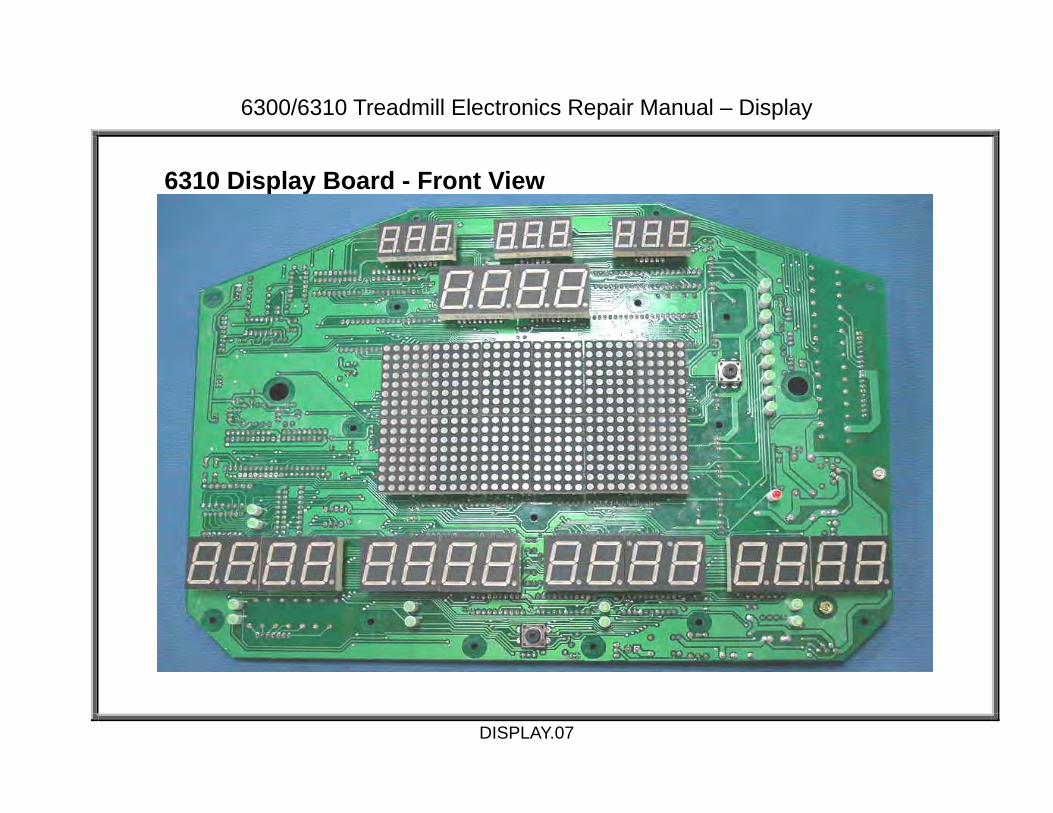
6310 Display Board - Front View
DISPLAY.07

6300/6310 Treadmill Electronics Repair Manual – Drive
6300/6310 Drive Board – Includes 6300/6310 Drive Board Wiring, LEDs DRIVE BOARD.01 – Drive Board Wire Connection Diagram DRIVE BOARD.02 – 6300/6310 Drive Board Wire Connection Picture DRIVE BOARD.03 – 6300/6310 Drive Board LEDs – Normally Lit DRIVE BOARD.04 – 6300/6310 Drive Board LEDs – Normally Not Lit DRIVE BOARD.05 – 6300/6310 Drive Board Picture
DRIVE.00

6300/6310 Treadmill Electronics Repair Manual – Drive
Drive Board Wire Connections
Display Board
Drive Board
VR
Stride Motor
Motor Optic Sensor
Inductor(6310 Only)
FUSE
EMIFilter
On/OffSwitch
ThermalFuse
Transformer
PowerCord
DRIVE.01

6300/6310 Treadmill Electronics Repair Manual – Drive
6300/6310 Drive Board Connection Picture
DRIVE.02
CON6 Connects to
optic sensor.
CIN4 遮斷器接線
CON4, CON5 Connects to display
board.
CON3 Connects to incline
motor.
CIN4 遮斷器接線
L1, L2 Connects to inductor.
CON1 Connects to
transformer.
L1,L2 接至電感器
M+, M- Connects to
motor.
L1,L2 接至電感器
AC1, AC2 Connects to power switch.
CON2 Connects to
incline VR.
CON7 Connects to motor thermal
fuse.

6300/6310 Treadmill Electronics Repair Manual – Drive
6300/6310 Drive Board LEDS – Normally Lit
DRIVE.03
LED10 “CLK” LED Lights to indicate
reception of optic sensor signal.
LED3 Incline “DOWN” LED Lights when incline DOWN is
pressed. Indicates power to incline.
LED4 Incline “UP” LED Lights when incline UP is pressed.
Indicates power to incline.
LED1 “ON” LED Lights when power switch is
turned on. Extinguishes when emergency knob is activated or unit is off.
LED6 “SOFT” Circuit LED Lights two seconds after
unit power comes on. Extinguishes when emergency knob is pressed or unit is turned off.
LED2 “VCC” Circuit LED Lights when power
switch is on. Indicates VCC (display) circuit power.
LED9 “Belt Pull” LED Lights normally. Extinguishes if
belt if pulled faster than speed setting.
6300/6310 Treadmill Electronics Repair Manual – Drive
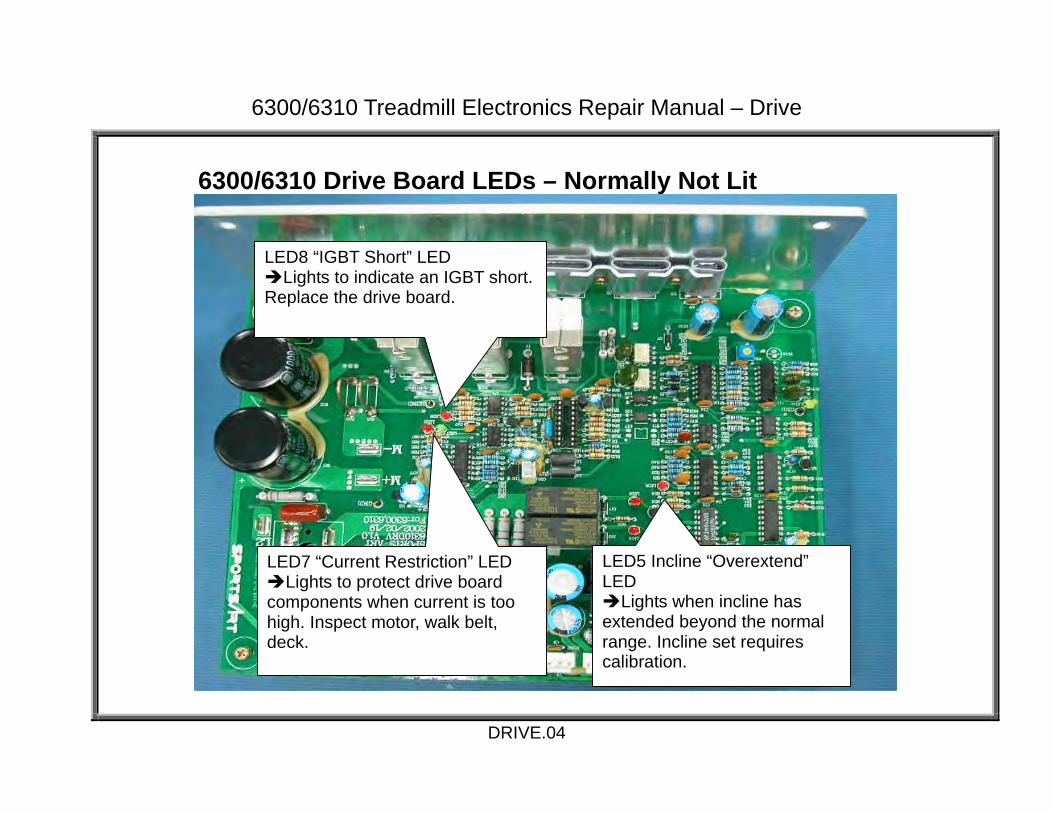
6300/6310 Drive Board LEDs – Normally Not Lit
DRIVE.04
LED7 “Current Restriction” LED Lights to protect drive board
components when current is too high. Inspect motor, walk belt, deck.
LED8 “IGBT Short” LED Lights to indicate an IGBT short.
Replace the drive board.
LED5 Incline “Overextend” LED
Lights when incline has extended beyond the normal range. Incline set requires calibration.
6300/6310 Treadmill Electronics Repair Manual – Drive
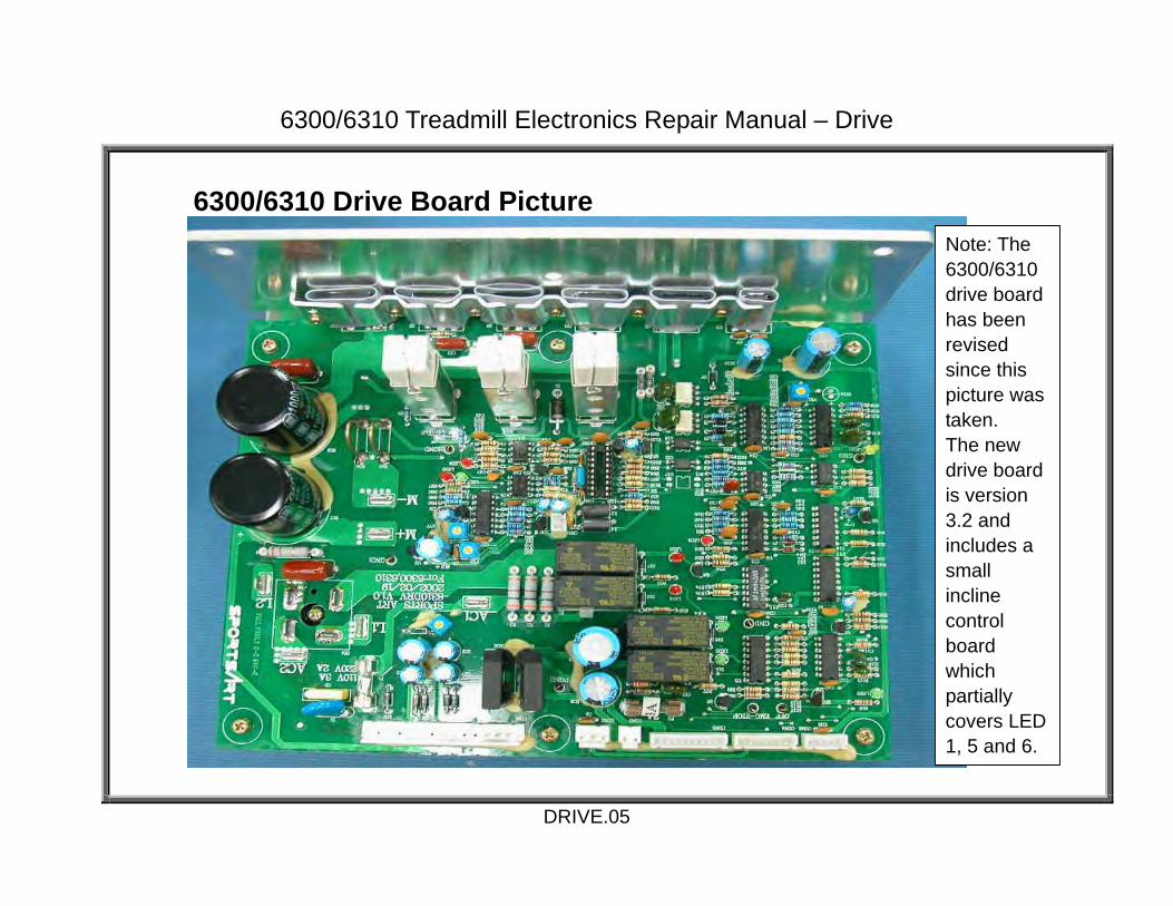
6300/6310 Drive Board Picture
DRIVE.05
Note: The 6300/6310 drive board has been revised since this picture was taken. The new drive board is version 3.2 and includes a small incline control board which partially covers LED 1, 5 and 6.

6300/6310 Treadmill Electronics Repair Manual – Motor
6300/6310 Drive Motor System Operation MOTOR.01 – 6300/6310 Motor System Operation MOTOR.02 – 6300/6310 Voltage to Motor – Test Configuration MOTOR.03 – 6300/6310 Voltage to Motor – Test Procedure, Test Results MOTOR.04 – 6300/6310 Motor Circuit and OHM Test Configuration, Procedure MOTOR.05 – 6300/6310 Transformer Test Configuration MOTOR.06 – 6300/6310 Transformer Test Procedure, Results MOTOR.07 – 6300/6310 Inductor Test Configuration, Procedure MOTOR.08 – 6300/6310 Optic Sensor Signal Test MOTOR.09 – 6300/6310 Optic Sensor Signal Test Procedure, Results
MOTOR.00
6300/6310 Treadmill Electronics Repair Manual – Motor
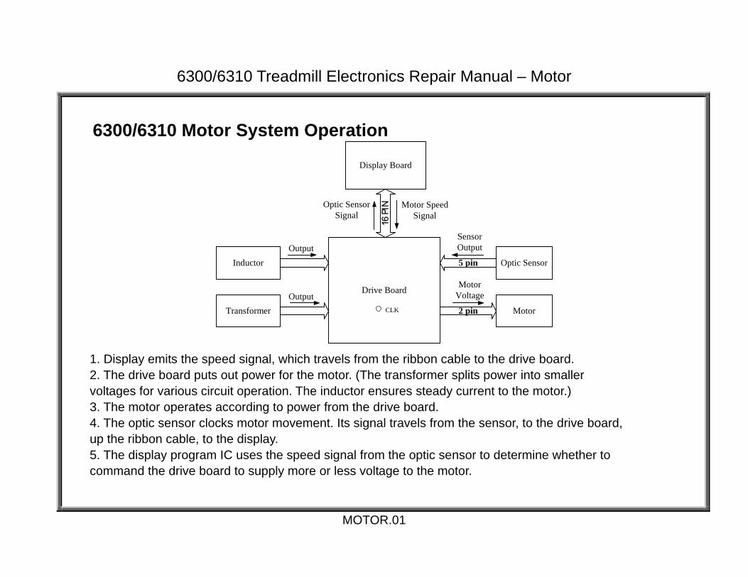
6300/6310 Motor System Operation
Display Board
Drive Board
Motor2 pin
MotorVoltage
Motor SpeedSignal
Inductor
TransformerOutput
16 P
INOptic SensorSignal
CLK
Optic Sensor5 pin
SensorOutputOutput
MOTOR.01
1. Display emits the speed signal, which travels from the ribbon cable to the drive board. 2. The drive board puts out power for the motor. (The transformer splits power into smaller voltages for various circuit operation. The inductor ensures steady current to the motor.) 3. The motor operates according to power from the drive board. 4. The optic sensor clocks motor movement. Its signal travels from the sensor, to the drive board, up the ribbon cable, to the display. 5. The display program IC uses the speed signal from the optic sensor to determine whether to command the drive board to supply more or less voltage to the motor.

6300/6310 Treadmill Electronics Repair Manual – Motor
6300/6310 Voltage to Motor – Test Configuration
MOTOR.02

6300/6310 Treadmill Electronics Repair Manual – Motor
6300/6310 Voltage to Motor – Test Procedure 1. Put multimeter to the DC voltage setting. Place probes as shown on the drive board M+ and M- connectors. 2. Turn on unit power. Press SPEED<▲> key. The multimeter should show an increase in voltage. The motor should operate. At the highest speed (12.0 MPH), the multimeter should show 100-120 VDC. 6300/6310 Voltage to Motor – Test Results If there is no voltage across M+ and M- connectors, the drive board is not supplying power. Inspect the following: 1.Drive board power indicator, LED2. If LED2 does not light, trace power from the wall into the unit, to see where the power stops. Also, inspect fuses. 2.Drive board IGBT short indicator, LED8. If LED8 lights, the IGBT has a short. Replace the drive board. 3.Transformer and its wire connectors. See TESTING – TRANSFORMER.1. 4.Test the drive board by replacing it with a new one. If the drive board does provide power, but the motor does not operate, inspect the motor wire connections. If the wires are good and the connections are good, but the motor does not operate, the motor is bad. Replace it.
MOTOR.03
6300/6310 Treadmill Electronics Repair Manual – Motor
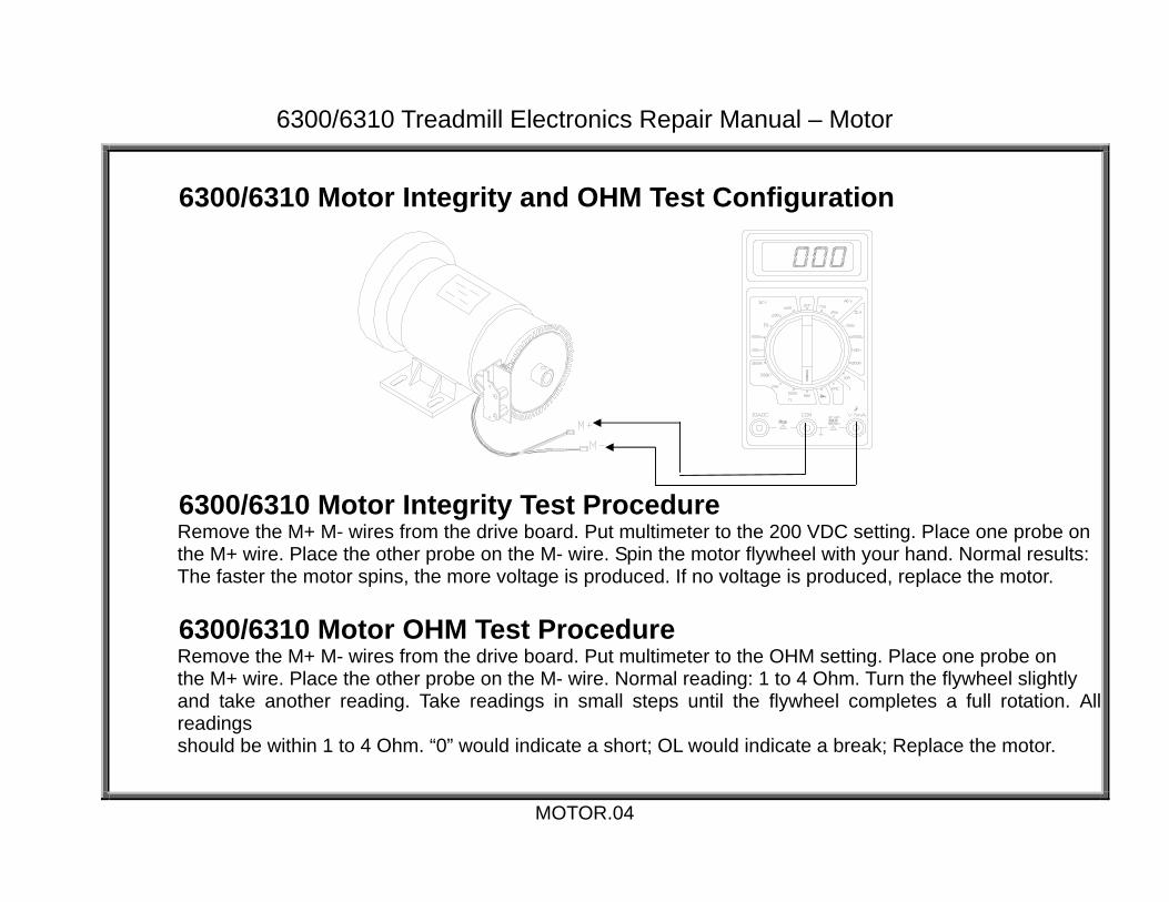
6300/6310 Motor Integrity and OHM Test Configuration
6300/6310 Motor Integrity Test Procedure Remove the M+ M- wires from the drive board. Put multimeter to the 200 VDC setting. Place one probe on the M+ wire. Place the other probe on the M- wire. Spin the motor flywheel with your hand. Normal results: The faster the motor spins, the more voltage is produced. If no voltage is produced, replace the motor.
6300/6310 Motor OHM Test Procedure Remove the M+ M- wires from the drive board. Put multimeter to the OHM setting. Place one probe on the M+ wire. Place the other probe on the M- wire. Normal reading: 1 to 4 Ohm. Turn the flywheel slightly and take another reading. Take readings in small steps until the flywheel completes a full rotation. Allreadings should be within 1 to 4 Ohm. “0” would indicate a short; OL would indicate a break; Replace the motor.
MOTOR.04

6300/6310 Treadmill Electronics Repair Manual – Motor
6300/6310 Transformer Test - Configuration
MOTOR.05
CON1 Transformer Wire Connector
Drive Board
Transformer

6300/6310 Treadmill Electronics Repair Manual – Motor
6300/6310 Transformer Test Procedure 1. Make sure that transformer wire connections (CON1) to the drive board are secured. Turn unit on. 2. Put multimeter to the AC voltage setting. Insert meter probes into the transformer primary (red) wires as shown. Normal reading: 110V. This shows that there is power to the transformer. 3. Test transformer output by probing on secondary (output) wires: black and black, white and white, orange and orange, yellow and yellow.
6300/6310 Transformer Test Results 1. If there is no voltage across the primary (red) wires, inspect F1 fuse on the drive board and power to the drive board. 2. If there is voltage across primary wires but none across secondary wires, the transformer is bad. Replace it.
Transformer Wire Colors Normal Voltage Value
Red and Red 110 VAC Black and Black 11-13 VAC White and White 11-13 VAC Orange and Orange 27-29 VAC Yellow and Yellow 10-12 VAC
MOTOR.06

6300/6310 Treadmill Electronics Repair Manual – Motor
6300/6310 Inductor Test Configuration
6300/6310 Inductor Test Procedure 1. Disconnect the inductor wires from the drive board. 2. Put multimeter to the Ohm setting. Place one probe on each wire end. 3. Normal reading: 0.4 Ohm. 4. If there is no reading (OL), or a reading of 0 Ohm, or if the inductor makes a “wong” sound as the user’s heel strikes the belt, replace the inductor.
MOTOR.07

6300/6310 Treadmill Electronics Repair Manual – Motor
6300/6310 Optic Sensor Signal Test
MOTOR.08
Optic Sensor Board
Optic Sensor Wheel
LED10 CLK LED

6300/6310 Treadmill Electronics Repair Manual – Motor
6300/6310 Optic Sensor Signal Test Procedure Turn on unit power. Do not press display keys. Use your hand to rotate the motor flywheel. Normal result: LED 10 lights to indicate the optic sensor signal entering the drive board. The LED appears to flicker at a low speed and remain lit at high speed. 6300/6310 Optic Sensor Signal Test Results If LED10 does not light, inspect: 1. Optic sensor signal wires and their connections; Reinsert wire ends into connectors. 2. Whether optic sensor wheel rotates in the middle of the sensor; If not, reinstall the optic sensor wheel. 3. Whether optic sensor wheel teeth are broken or bent; if so, replace the optic sensor wheel. 4. If LED2, the VCC circuit indicator, on the drive board lights and there is no optic sensor signal output (LED10 does not light), and if optic sensor wires and connections are good, replace the optic sensor.
MOTOR.09

6300/6310 Treadmill Electronics Repair Manual – Incline
6300/6310 Incline System Operation INCLINE.01 – 6300/6310 Incline System Operation INCLINE.02 – 6300/6310 Voltage to Incline Motor – Test Configuration INCLINE.03 – 6300/6310 Voltage to Incline Test Procedure, Results INCLINE.04 – 6300/6310 Incline VR Voltage –Test Configuration INCLINE.05 – 6300/6310 Incline VR Voltage Test Procedure, Results
INCLINE.00

6300/6310 Treadmill Electronics Repair Manual – Incline
6300/6310 Incline System Operation
Display Board
Drive Board
Incline Motor2 pin
MotorVoltage
InclineCommand
TransformerOutput
16 P
INIncline VRSignal
LED3 - Incline DownLED4 - Incline Up
Incline VR3 pin
VROutput
INCLINE.01
1. Display emits the incline signal, which travels from the ribbon cable to the drive board. 2. The transformer breaks wall power down into smaller voltages for various circuit operation, including the incline motor. 3. The drive board puts out power for the motor. Up operation: K4 relay clicks, LED 4 lights. Down operation: K2 relay clicks, LED 3 lights. 4. The incline motor operates according to power from the drive board. UP operation: K4 relay clicks, LED 4 lights. Down operation: K2 relay clicks, LED 3 lights. 5. As the incline motor moves, the variable resistor (VR) moves, changing VR output voltage. The VR voltage travels to the drive board, up the ribbon cable, to the display. 6. The display program IC uses the VR signal to determine the position of the incline. This is used to determine whether to supply or cut off power for incline motor operation.

6300/6310 Treadmill Electronics Repair Manual – Incline
6300/6310 Voltage to Incline Motor - Test Configuration
INCLINE.02

6300/6310 Treadmill Electronics Repair Manual – Incline
6300/6310 Voltage to Incline Test Procedure 1. Put multimeter to the DC Voltage setting. Insert the red probe into the CON3 white wire connector. Insert the black probe into the CON3 green wire connector. Turn on unit power. 2. Press INCL<▲> key. K4 relay clicks; LED4 lights. Normal reading: +35 VDC. Incline operates up.
3. Press INCL<▼> key. K2 relay clicks; LED3 lights. Normal reading: -35 VDC. Incline operates down. 6300/6310 Voltage to Incline Test Results If not as above, inspect the following: 1. In manual mode, press an incline up or down key. The display should beep once. If not, inspect the display. 2. Test the transformer voltage (see TESTING - TRANSFORMER.1 in Motor System Operation); Check for 35 VDC across the orange wires. 3. If LED 5 on the drive board lights or ERR7 appears, recalibrate the incline set and test incline operation again. 4. If the display beeps when incline keys are pressed, but the drive board incline up and down LEDs don’t light, inspect the ribbon cable (check continuity). If the ribbon cable is good and the transformer is good, replace the drive board.
INCLINE.03

6300/6310 Treadmill Electronics Repair Manual – Incline
6300/6310 Incline VR Voltage - Test Configuration
INCLINE.04

6300/6310 Treadmill Electronics Repair Manual – Incline
6300/6310 VR Voltage Test Procedure 1. Put multimeter to the DC Voltage setting. Place one probe on the CON2 connector blue wire. Place the other probe on the CON2 connector green wire. 2. Turn on unit power. Normal reading: 1.10 to 3.60 VDC. 3. Press the INCL<▲> key until the incline window shows 15%. The incline arrives at the highest position. Normal reading: 3.80 VDC. 4. Press the INCL<▼> key until the incline window shows 0%. The incline arrives at the lowest position. The red line on the thin pipe is visible just above the red line on the thick pipe. Normal reading: 1.20 VDC. 6300/6310 VR Voltage Test Results 1. If not as above, recalibrate the VR and incline motor. 2. If the VR voltage jumps during incline operation or fails to calibrate properly, replace the VR.
INCLINE.05

6300/6310 Treadmill Electronics Repair Manual – Calibration
6300/6310 Incline Calibration CALIBRATION.01 – 6300/6310 Incline Calibration Overview CALIBRATION.02 – Mechanical Calibration CALIBRATION.03 – Electronic Calibration CALIBRATION.04 – Incline Calibration Testing
CALIBRATION.00

6300/6310 Treadmill Electronics Repair Manual – Calibration
6300/6310 Incline Calibration Overview Incline calibration is necessary when:
the display shows ERR7; the drive board incline error LED ( LED5) lights; or the incline has extended beyond its normal range.
The goal of calibration is to synchronize the incline set mechanically and electronically.
Mechanical calibration sets the incline motor pipe to the 0% position. This happens when the red line on the thin pipe is even with the end of the thick pipe.
Electronic calibration sets the variable resistor (VR) value to the 0% position. This happens when the voltage across the VR blue and green wires is 1.20 VDC.
CALIBRATION.01

6300/6310 Treadmill Electronics Repair Manual – Calibration
Mechanical Calibration
Step 1. Turn the unit on its side, Step 2. Turn the incline motor pipe until and pull out the incline pin. the red line on the thin pipe is visible just above the end of the thick pipe.
Step 3. Insert the incline pin. Step 4. Right the unit and remove the motor cover.
CALIBRATION.02

6300/6310 Treadmill Electronics Repair Manual – Calibration
Electronic Calibration
Step 1. Remove the VR cover Step 2. Set multimeter to the DC volt setting. Insert multimeter but do not detach VR wires. probes into the VR blue and green wire connectors on the drive board.
Step 3. Turn the VR gear until the multimeter shows 1.20 VDC. Step 4. Secure the VR, then secure motor cover.
CALIBRATION.03

6300/6310 Treadmill Electronics Repair Manual – Calibration
Incline Calibration Testing Test the calibration by running the incline.
At the physical 0% position, the display should show 0% incline. At the physical 15% position, the display should show 15% incline. Incline operation should be smooth. Readings of VR voltage (blue and green wires) should show around 1.20 VDC at the lowest position
and around 3.80 VDC at the highest position. If the VR looses calibration or cannot be set to 1.20 VDC, replace the VR. If the incline motor gets voltage from the drive board but fails to operate, replace the incline motor set. If the incline fuse blows again and again, replace the incline motor set.
CALIBRATION.04

6300/6310 Treadmill Electronics Repair Manual – Heart Rate
6300/6310 Heart Rate System Operation
HR.01 – Heart Touch Rate (HTR) Operation HR.02 – POLAR Heart Rate (HR) Operation HR.03 – HTR Board LED Operation, LED Indicator Definitions HR.04 – Possible Malfunctions, Troubleshooting HR.05 – HTR Cable/Handlebar Test Procedure
HR.00

6300/6310 Treadmill Electronics Repair Manual – Heart Rate
Heart Touch Rate (HTR) Operation
Display BoardHTR心跳小板 3 PIN CABLE
PULSE
HTRHANDLE BAR
HTRHANDLE BAR
Order Part Operation
1
HTR Handlebar
1.Place both hands on the HTR handlebars. The handlebars detect the user’s pulse.2.The pulse signal travels across wires from the handlebars to the HTR board. 3.LED2 and LED4 on the HTR board light up when the user holds onto the handlebars.
2
HTR Board 1.The HTR board receives, processes, and transmits pulse signals. 2.LED3 flashes each time an incoming pulse signal is received. 3.LED4 flashes each time an outgoing pulse signal is sent to the display board. 4.The HTR board sends its heart rate signal to the display board.
3 3-PIN Cable 1.The heart rate signal travels the 3-pin cable from the HTR board to the display board.
4 Display 1. The display board CPU detects the digital heart rate signal and determines the heart rate value. 2. The display PULSE window shows the heart rate value.
HR.01
HTR Board
HTR Handlebar
HTR Handlebar

6300/6310 Treadmill Electronics Repair Manual – Heart Rate
POLAR Heart Rate (HR) Operation
Order Part Operation
1 HR Transmitter
1. User wears the POLAR heart rate strap. 2. POLAR transmitter detects the user’s heart rate. 3. Then it transmits the heart rate signal to the receiver.
2 POLAR HR Receiver
1. The POLAR receiver board receives the POLAR transmitter signal. 2. The POLAR signal goes to the HTR board. After processing the heart rate signal, the HTR board sends it to the display board.
3 3-pin Cable 1. The heart rate signal travels the 3-pin cable from the HTR board to the display board.
4 Display 1. The CPU detects the heart rate signal. 2. The display shows the heart rate value.
HR.02
POLAR HR Transmitter
POLAR Receiver Board
HTR Board
Display Board
3-pin Cable
6300/6310 Treadmill Electronics Repair Manual – Heart Rate
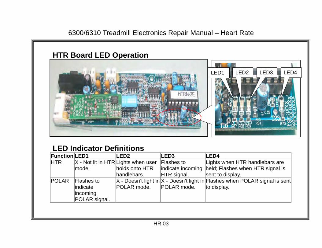
HTR Board LED Operation
LED Indicator Definitions Function LED1 LED2 LED3 LED4 HTR X - Not lit in HTR
mode. Lights when user holds onto HTR handlebars.
Flashes to indicate incoming HTR signal.
Lights when HTR handlebars are held; Flashes when HTR signal is sent to display.
POLAR Flashes to indicate incoming POLAR signal.
X - Doesn’t light in POLAR mode.
X - Doesn’t light in POLAR mode.
Flashes when POLAR signal is sent to display.
HR.03
LED1 LED2 LED3 LED4

6300/6310 Treadmill Electronics Repair Manual – Heart Rate
Possible Malfunctions 1. Strap on a Polar heart rate transmitter or hold onto the HTR handlebar. The display PULSE window shows no heart rate value. 2. The PULSE window shows the heart rate value inappropriately – when no one touches the HTR handlebar or when no one wears the Polar strap. 3. Place hands on the HTR handlebar or wear the Polar strap. The display PULSE window value differs greatly from the user’s actual heart rate.
Troubleshooting
Malfunction Cause Inspect
LED1 (POLAR) not flashing
POLAR receiver is not detecting a heart rate or the signal is not getting to the HTR board.
POLAR transmitter, POLAR receiver board, wires
LED2 (HTR) not lighting
HTR handlebar is not being held or there is no detection of a signal at the HTR board.
HTR handlebar, wire from HTR board to handlebar (See HR.05.)
LED3 (HTR) not flashing
Signal is not arriving from HTR handlebars. HTR handlebar, cable, HR board (See HR.05.)
LED4 (HTR+POLAR) not flashing
POLAR receiver or HTR is not emitting a heart rate signal to the display.
If all other HTR board LEDs are normal, replace the HTR board.
Display Shows No HR Value
If HTR board LEDs are normal, inspect the 3-pin cable, its connections, and the display board.
3-pin cable, connections, display board
HR.04

6300/6310 Treadmill Electronics Repair Manual – Heart Rate
HTR Cable/Handlebar Test Procedure A lack of continuity or a short in the wiring between the HTR board and handlebars could result in either no heart rate reading, intermittent readings, or bad heart rate readings. Follow directions below to test the 5-pin HTR cable. (1) Turn off unit power. Remove the 5-pin cable from the HTR board. (2) Set multimeter to read continuity. (If your multimeter does not have an audible continuity setting, set your meter to the 200 OHM setting. A reading of 0 ohms is direct continuity. No reading or OL (open line), indicates no continuity.) Place probes as indicated in Fig. 1 and 2 below. (3) Normal readings are shown in the charts below. Fig. 1. Place red probe on points here. Fig. 2. Place black probe on points here.
Continuity Test Short Test a to A Conductivity GND to A No Conductivity b to B Conductivity GND to B No Conductivity c to C Conductivity GND to C No Conductivity d to D Conductivity GND to D No Conductivity GND to Frame No Conductivity
Note: Around Oct. 2004, HTR handlebars changed. One contact plate was used on each side. The picture shows two plates, one on top, one on the bottom, on each side. Testing is similar, but two wires will be open – not conductive.
HR.05
B
D
C
GND
a
c
b
d A
Left Right

6300/6310 Treadmill Electronics Repair Manual – Troubleshooting
6300/6310 Troubleshooting
ERR1.01 – ERR 1 – Motor Movement ERR1.02 – Troubleshooting: ERR1 Motor Movement ERR1.03 – ERR 1 – No Motor Movement ERR1.04 – Troubleshooting: ERR1 Motor Movement ERR3.01 – ERR 3 ERR3.02 – ERR 3 Troubleshooting ERR7.01 – ERR7 ERR7.02 – ERR7 Troubleshooting NO DISPLAY.01 – Display Does Not Light NO DISPLAY.02 – Troubleshooting: Display Does Not Light
ERR.00

6300/6310 Treadmill Electronics Repair Manual – Troubleshooting
ERR 1 – Motor Movement ERR1 indicates a speed issue. In this case, the motor speed as reported from the optic sensor differs from the speed setting. Analysis: Optic sensor signal issue -- Either the optic sensor signal is not right, or it is read incorrectly, or the signal is not reaching the display.
Display Board
Drive Board
Motor2 pin
Motor SpeedSignal
16 P
INOptic SensorSignal
CLK
Optic Sensor5 pin
Optic SensorSignal Output
ERR1.01

6300/6310 Treadmill Electronics Repair Manual – Troubleshooting
Troubleshooting: ERR1 – Motor Movement Since the motor moves when you press speed up, focus on the optic sensor, its wire connections, and the optic sensor wheel. If all seems well at the sensor, inspect the motor. Optic Sensor
Optic sensor wheel - Make sure that the optic sensor wheel rotates securely, without wobbling, in the middle of the optic sensor. Realign and tighten if necessary. If optic sensor wheel teeth are missing or bent, replace the optic sensor wheel.
Optic sensor wires – Make sure that wires are inserted securely to the optic sensor and to the drive board. Check wire continuity.
Optic sensor – Turn on unit power. Turn the motor flywheel with your hand. The optic sensor indicator (LED10, drive board) should light. See MOTOR.08. If it does not light, and all parts above are good, replace the optic sensor. Motor
Motor arcing – Does the motor show signs of wear – irregular arcing, carbon dust? Motor brushes – Do brushes show signs of irregular wear – cracks, dents, lines? Replace the
motor brushes. M+ M- Wires - Make sure wires are connected properly.
Other
Display main IC - To ensure proper signal processing, press down on the main IC on the display board, marked U5. See DISPLAY.06.
Ribbon cable – Ensure that the ribbon cable is attached at the drive and display boards. Check cable continuity.
ERR1.02

6300/6310 Treadmill Electronics Repair Manual – Troubleshooting
ERR 1 – No Motor Movement
ERR1 indicates a speed issue. In this case, the motor does not operate when it should. Analysis: Either the drive board is not putting out power to the motor, or the motor is malfunctioning.
Display Board
Drive Board
Motor2 pin
MotorVoltage
Motor SpeedSignal
Inductor(6310 Only)
Transformer
TransformerVoltage
16 P
INOptic SensorSignal
CLK
ERR1.03

6300/6310 Treadmill Electronics Repair Manual – Troubleshooting
Troubleshooting: ERR 1 – No Motor Movement Turn unit power off and then on to clear the ERR1 message from the display. To test whether the drive board is putting out power to the motor, insert multimeter probes on the M+ M- connectors and press the speed up key. See MOTOR.02. (Note: To avoid ERR1 from immediately appearing, move the walk belt slowly with your feet.) Power to Motor If the drive board puts out power to the motor, but the motor does not operate, either the motor wires or motor is malfunctioning. Test wires for continuity. Inspect connections. Perform an ohm test on the motor (see MOTOR.04). Inspect motor brushes. No Power to Motor If there is no power to the motor, either the signal is not arriving at the drive board, the transformer or inductor is bad, or the drive board is bad. Inspect the following:
Display – Does the display beep when you press speed up? If so, the display has sent its signal. If not, inspect overlay-to-display connections. And press down on the main program IC, marked U5.
Wires and their connections – inspect data cable connections from the display to the drive board, test data cable continuity, inspect M+ M- wires from the drive board to the motor.
Inductor (6310 only) – inspect inductor and its wires and their connections. See MOTOR.07. Transformer – inspect the transformer and its wires and their connections. See MOTOR.05. Drive Board – inspect the drive board for burnt or cracked components. Inspect LEDs (See DRIVE.03
and DRIVE.04). Press on the drive board IC chips to ensure good connection. If the power indicator on the drive board, LED8, lights, but there is no power to the motor, and other components are good, replace the drive board.
ERR1.04

6300/6310 Treadmill Electronics Repair Manual – Troubleshooting
ERR 3 ERR3 indicates that the actual unit speed differs from the speed setting. Unlike older SportsArt treadmills, though, ERR3 cannot be produced in 6300/6310 models by the user pulling the belt faster than the speed setting. Resolve an ERR3 issue much like you would an ERR1 with belt movement: check the optic sensor first. Other possible causes include a bad drive board motor circuit creating irregular power supply and a poorly connected main program IC.
Display Board
Drive Board
Motor
Optic SensorSignal
CLK Optic Sensor4 pin
Optic SensorSignal
Motor SpeedCommand
ERR3.01

6300/6310 Treadmill Electronics Repair Manual – Troubleshooting
ERR 3 Troubleshooting Inspect the optic sensor and other components as follows. Optic Sensor
Optic sensor wheel – Make sure that the optic sensor wheel rotates securely, without wobbling, between the black optic sensor nubs. Realign and tighten if necessary. If optic sensor wheel teeth are missing or bent, replace the optic sensor wheel.
Optic sensor wires – Check wire connections from the optic sensor to the drive board. Check wire continuity .
Optic sensor – Turn on unit power. Turn the motor flywheel with your hand. The optic sensor indicator (LED10 on the drive board) should flicker. See MOTOR.08. If it does not light, and all parts above are OK, replace the optic sensor. Other
Motor – Does the motor sputter, sometimes running fast, sometimes slow? See MOTOR.04. If the motor tests good, replace the drive board. If the motor tests bad, replace it.
Drive board – See above, and inspect for burnt, damaged, or loose components. Main program IC - Press down on the main program IC on the display to ensure a good connection.
Replace the IC if necessary.
ERR3.02

6300/6310 Treadmill Electronics Repair Manual – Troubleshooting
ERR 7
Either the main program IC didn’t detect the incline VR voltage, or the incline VR voltage exceeds the range setting.
Display Board
Drive Board
Incline VRVoltage
Incline Motor
Incline VR
CA
BLE
Incline VRVoltage
LED5 ERR
ERR7.01

6300/6310 Treadmill Electronics Repair Manual – Troubleshooting
ERR 7 Troubleshooting
ERR7 is an incline system VR error. Check the incline VR first. Other possible causes include a bad data cable, drive board IC, and display IC. LED 5 on the drive board lights when the VR exceeds the set range. Incline System
Wire Connections – Make sure that CON4 and 5 connectors are fastened securely. Incline Set – If the incline pipe is stuck or overextended, recalibrate. See CALIBRATION.01. VR – Back-probe across the incline VR blue and green wires. Normal range: 1.1 to 4.0.
Recalibrate the incline VR if values exceed this range. See CALIBRATION.01. If the VR will not calibrate, replace it.
Other Drive board – The drive board should supply 5 VDC power to the incline VR. Test by back-probing
on the VR green and red wires. Also, press on drive board IC U20, marked 63DRV-1A, to ensure a good connection.
Display board – Press on display board ICs U5 (main program) and U3 (ADC0804) to ensure good connections.
Data cable – Inspect for broken or shorted wires. Perform continuity test on the cable.
ERR7.02

6300/6310 Treadmill Electronics Repair Manual – Troubleshooting
Display Does Not Light Malfunction: Turn on unit power. Display does not beep once; display LEDs do not light.
Display Board
Drive Board
FUSE
EMIFilter
On/OffSwitch
PowerCord
Transformer
FUSEF1
NO DISPLAY.01

6300/6310 Treadmill Electronics Repair Manual – Troubleshooting
Troubleshooting: Display Does Not Light Trace the power into the unit. The problem exists where the power desists.
Power socket in the wall - Provides 110 to 120 VAC. If not, inspect the circuit breaker. Power cord – Make sure cord is plugged in properly. Inspect output. Fuse holder – Replace 15 Amp fuse if necessary. Inspect that power comes out of fuse holder. On/Off switch – Switch lights when “ON” and extinguishes when “OFF”. Inspect for output. EMI filter – Inspect for output by back-probing on AC1 and AC2 wires to the drive board.
Normal reading: 110 to 120 VAC. Transformer – Inspect for input and output. (See MOTOR.02.) Drive board – LED2 lights when drive board has power. (See DRIVE.03.) Test F1 3A fuse for continuity.
(See DRIVE.05, lower left.) Make sure that wires, in particular CON3 and 4, are connected securely. Data cable – Make sure data cable is securely plugged into the display and drive boards. Test cable
for continuity. Display – LED21 lights when display has power. (See DISPLAY.03.) Power to display can also be
confirmed by probing on capacitors. Capacitor C26 voltage: 5 VDC. (See DISPLAY.04.) Capacitor C41 voltage: 14 VDC. (See DISPLAY.05.) (Electronic engineer replace U17 PW-8051.) Press down on main program IC U5 to ensure a good connection. (See DISPLAY.06.) Press down on LEDs to ensure a good connection.
NO DISPLAY.02

6300/6310 Treadmill Electronics Repair Manual – Testing
Testing Components Unique to 6300/6310 Treadmills FILTER.01 – EMI Filter FILTER.02 – EMI Filter Test THERMAL FUSE.01 – Thermal Fuse Placement THERMAL FUSE.02 – Thermal Fuse Operation THERMAL FUSE.03 – Thermal Fuse Troubleshooting EMERGENCY STOP.01 – Emergency Stop Signal Diagram, Emergency Stop Knob Operation EMERGENCY STOP.02 – Emergency Stop Knob Troubleshooting, Emergency Stop Knob Test Configuration EMERGENCY STOP.03 – Emergency Stop Revision KEYS.01 – Key Operation, Key Test Configuration KEYS.02 – Key Test Procedure
TESTING.00

6300/6310 Treadmill Electronics Repair Manual – Testing
EMI Filter The EMI filter prevents interference to other electronic products. A malfunctioning filter would allow Interference to other product operation or possibly prevent voltage from arriving to the drive board. EMI Filter Test Put the multimeter to the ohm setting. Place probes as shown below.
Test 1. Point A to Point B; Normal reading: 0.4 ohm. Test 2. Point C to Point D. Normal reading: 0.4 ohm.
FILTER.01
A
B D
C
6300/6310 Treadmill Electronics Repair Manual – Testing
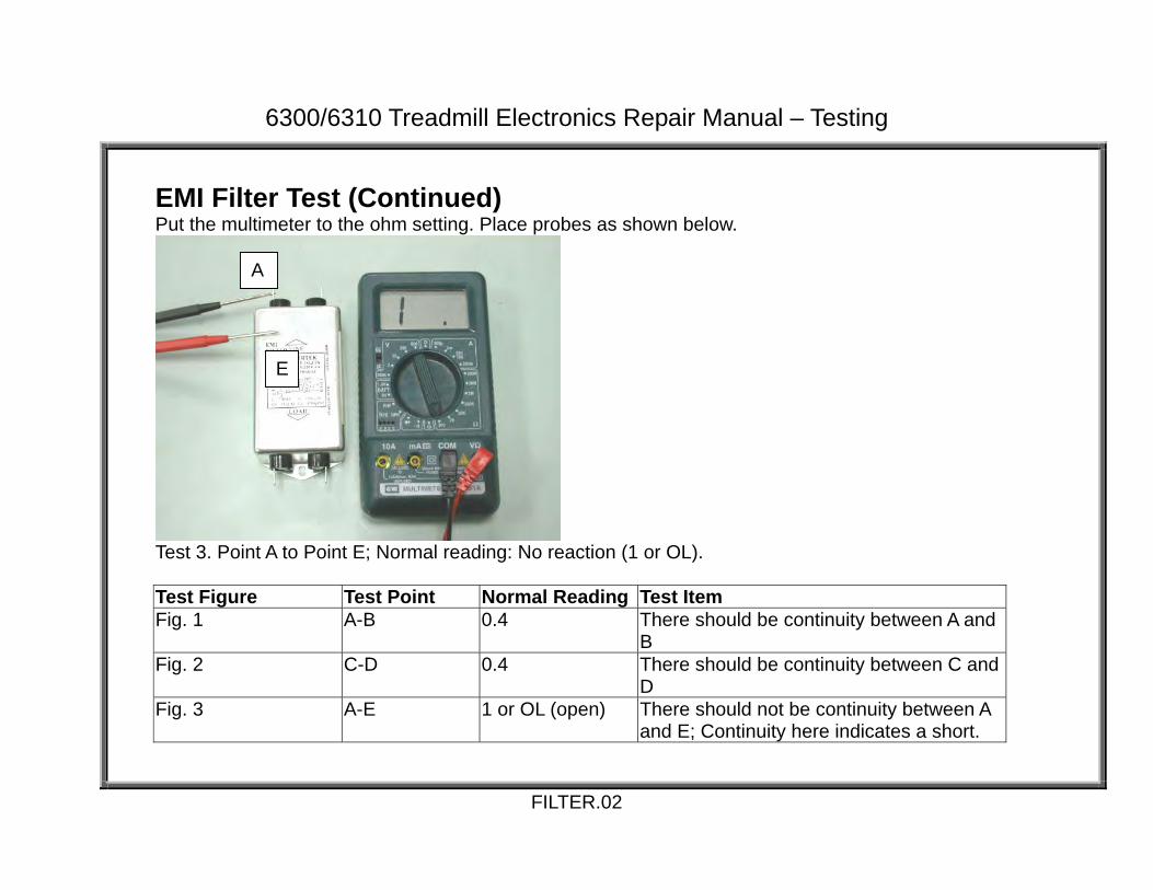
EMI Filter Test (Continued) Put the multimeter to the ohm setting. Place probes as shown below.
Test 3. Point A to Point E; Normal reading: No reaction (1 or OL). Test Figure Test Point Normal Reading Test Item Fig. 1 A-B 0.4 There should be continuity between A and
B Fig. 2 C-D 0.4 There should be continuity between C and
D Fig. 3 A-E 1 or OL (open) There should not be continuity between A
and E; Continuity here indicates a short.
FILTER.02
A
E

6300/6310 Treadmill Electronics Repair Manual – Testing
Thermal Fuse Placement
THERMAL FUSE.01
Thermal Fuse Connector Wire
Thermal Fuse
Motor Thermal Fuse Wire Connection to Drive Board
Drive Motor

6300/6310 Treadmill Electronics Repair Manual – Testing
Thermal Fuse Operation
Display Board
Drive Board
Motor
Thermal FuseSignal
CLK Thermal Fuse
Thermal FuseSignal
THERMAL FUSE.02
1. When the motor temperature gets too high, the thermal fuse “breaks,” cutting continuity to the thermal fuse circuit. 2. The break in continuity serves as a signal, which travels to the drive board then to the display. 3. The display main program IC reacts: “Service required” indicator lights on the display. On later units, the motor is shut off too. For details, see above right.
Design Change Implementation Model, Date, IC, Serial Number 6300, 03/30/04, M63T-4B, 0077981; 6310, 04/27/04, B631H-4B, 0078117; 6320, 0091593, B632H-4B, 0091593; Information above marks the start of a thermal fuse operation design change. Before the change, the “Service Required” would light on the display after the thermal fuse was tripped. After the change, the motor would be shut down as well so the unit could not be used.

6300/6310 Treadmill Electronics Repair Manual – Testing
Thermal Fuse Troubleshooting If the “Service required” indicator lights, check the motor. Is it hot? If the motor is not hot, and the indicator lights, check the fuse wire and its connections. Replace the thermal fuse if wires and connections are good but the indicator lights when the motor is cool. If the motor is hot, inspect the deck and belt. Worn decks and belts produce friction, which causes the motor to draw more current and heat up. A walk belt that is too loose or too tight can cause more friction too. Replace belts and decks if necessary. The deck is two-sided and can be flipped. After taking action, let the motor cool for 30 minutes before starting up again.
THERMAL FUSE.03

6300/6310 Treadmill Electronics Repair Manual – Testing
Emergency Stop Knob Signal Diagram
Emergency Stop Knob Operation
Note: When not pressed down (left), the emergency stop knob circuit has continuity. When pressed down (right), the emergency stop knob circuit is an open line; there is no continuity.
1. While unit is in operation, press the emergency stop knob down. The circuit loses continuity. The display beeps once. Treadmill action stops. On 6300, the display main window shows: “_ _ _ _”. On 6310, the display main window shows: “RESET EMERGENCY STOP BUTTON”. 2. Rotate the emergency stop knob clockwise to reset. Emergency stop knob pops up. Circuit continuity is regained. Start up display appears.
EMERGENCY STOP.01
Display Board Emergency Stop Knob
2-pin wire

6300/6310 Treadmill Electronics Repair Manual – Testing
Emergency Stop Knob Troubleshooting If the emergency stop knob malfunctions – activating when it shouldn’t, or not activating when it should – inspect its wire connections, test wire continuity, and test the stop knob switch itself. Emergency Stop Knob Test Configuration
Test Procedure: Put multimeter to the Ohm setting. Place probes as shown. When the knob is not pressed down, the meter should read about 0.5 ohm (continuity). When the knob is pressed down, the meter should show no reaction, (open line), indicating no continuity. If your test results differ, replace the emergency stop knob.
EMERGENCY STOP.02
6300/6310 Treadmill Electronics Repair Manual – Testing
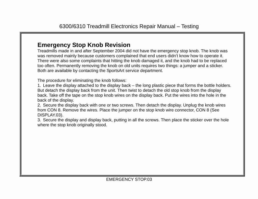
Emergency Stop Knob Revision Treadmills made in and after September 2004 did not have the emergency stop knob. The knob was was removed mainly because customers complained that end users didn’t know how to operate it. There were also some complaints that hitting the knob damaged it, and the knob had to be replaced too often. Permanently removing the knob on old units requires two things: a jumper and a sticker. Both are available by contacting the SportsArt service department. The procedure for eliminating the knob follows: 1. Leave the display attached to the display back – the long plastic piece that forms the bottle holders. But detach the display back from the unit. Then twist to detach the old stop knob from the display back. Take off the tape on the stop knob wires on the display back. Put the wires into the hole in the back of the display. 2. Secure the display back with one or two screws. Then detach the display. Unplug the knob wires from CON 8. Remove the wires. Place the jumper on the stop knob wire connector, CON 8 (See DISPLAY.03). 3. Secure the display and display back, putting in all the screws. Then place the sticker over the hole where the stop knob originally stood.
EMERGENCY STOP.03
6300/6310 Treadmill Electronics Repair Manual – Testing
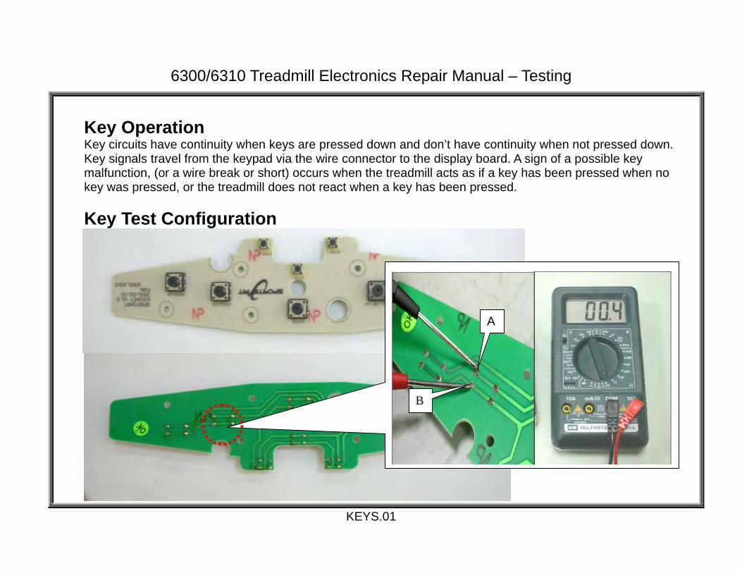
Key Operation Key circuits have continuity when keys are pressed down and don’t have continuity when not pressed down. Key signals travel from the keypad via the wire connector to the display board. A sign of a possible key malfunction, (or a wire break or short) occurs when the treadmill acts as if a key has been pressed when no key was pressed, or the treadmill does not react when a key has been pressed. Key Test Configuration
KEYS.01
B
A

6300/6310 Treadmill Electronics Repair Manual – Testing
Key Test Procedure Put multimeter to the ohm setting. Place probes as shown on points A and B. Normal reading when key is not pressed down: no reaction, OL or l (open line). Normal reading when key is pressed down: 0.4 ohm. Other keys can be tested similarly.
KEYS.02

6300/6310 Treadmill Electronics Repair Manual – Reference
Reference REF.01 – 6300/6310 Drive Board LED Reference Chart REF.02 – 6300/6310 Display LED Reference Chart, 6300/6310 Fuse Reference Chart REF.03 – VR Voltages for Various SportsArt Treadmill DC Incline Motors
REF.00

6300/6310 Treadmill Electronics Repair Manual – Reference
6300/6310 Drive Board LED Reference Chart LED Position Color Name Action 1 Mid left,
high Red Power Lights when power switch is on; extinguishes when power switch is turned off or when
the emergency knob is pressed. Relights when emergency knob is reset. 2 Left top Green VCC
power Lights when power switch is on. Indicates that drive board VCC circuit is operating; power is being sent to display.
3 Mid left high
Green Incline Down
Lights when incline operates down. Indicates that the display incline down signal has arrived at the drive board and the drive board is putting out power to the incline motor.
4 Mid left, under 3
Green Incline Up
Lights when incline operates up. Indicates that the display incline up signal has arrived at the drive board and the drive board is putting out power to the incline motor.
5 Mid left, center
Red Incline Error
Lights to indicate that the incline is overextended. Recalibration is necessary.
6 Mid left, under 1
Red “SOFT” Check
Immediately after the unit is turned on, the “SOFT” circuit shuts off motor power to prevent uncontrolled motor action. The “SOFT” LED lights two seconds after power switch is turned on; extinguishes when power switch is turned off or when the emergency knob is pressed. Relights when emergency knob is reset.
7 Mid right, low
Green High Amp
Lights when drive board current restriction circuit is activated. This occurs when the amp draw is too high. Inspect the motor, walk belt, deck. This LED is not lit under normal circumstances.
8 Mid right, low, by 7
Red IGBT Short
Lights when the IGBT has shorted. This LED is not lit under normal circumstances. If it lights, replace the drive board.
9 Mid right, low, by 7
Red Belt Pull
Lights normally. Turns off if belt is pulled faster than speed setting.
10 Right low Green Optic Sensor
Lights when the optic sensor signal enters the drive board. Flickers at low speeds; remains lit at high speeds. If it does not light when the motor flywheel moves, inspect the optic sensor, optic sensor wheel, and related wires.
Note: Positions are described as if you are looking at a drive board installed in the unit. Cable connectors are on top. The L- shaped aluminum plate is on the bottom. The left side has a row of ICs. Two large, black capacitors are on bottom right.
REF.01

6300/6310 Treadmill Electronics Repair Manual – Reference
6300/6310 Display LED Reference Chart LED Position Color Name Action LED 20 Top right Red C-Safe Lights to indicate that the display is supplying 5 VDC for C-SAFE operation.
LED lights regardless of whether C-SAFE power is actually being used. LED 21 Lower left Green Power Lights to indicate that the display is receiving power from the drive board, via
the ribbon cable.
6300/6310 Fuse Reference Chart FUSE Position Fuse
SpecificationsIf fuse breaks, install a new one of the same type and inspect the following:
Main Fuse On frame, near power switch
15A 250V (6x32mm) Slow
Fuse holder, On/Off switch, AC1, AC2 wiring, drive board, motor.
Fuse 1: Drive Board Power
On drive board, under CON1
3A 250V (5x20mm) Fast
Transformer, drive board.
Fuse 2: Incline
On drive board, under CON5
3A 250V (5x20mm) Fast
Incline motor, incline motor wiring.
REF.02

6300/6310 Treadmill Electronics Repair Manual – Reference
VR Voltages for Various SportsArt Treadmill DC Incline Motors
Incline Position Incline VR Range (Blue & Green) Model Low VR Voltage
Blue & Green Wires High VR Voltage
Blue & Green Wires 1210 0% 1.20 VDC 12% 3.30 VDC 3100/3120/3150 0% 3.55 VDC 15% 1.20 VDC 3106/3108/3110 0% 1.20 VDC 15% 3.80 VDC 3200/3250 0% 1.20 VDC 15% 3.55 VDC 6100/6150 0% 3.55 VDC 15% 1.20 VDC 6100E/6150E 0% 1.20 VDC 15% 3.55 VDC 6200/6200N/6260 -3% 1.20 VDC 22% 3.55 VDC 6300/6310 0% 1.20 VDC 15% 3.80 VDC 6320 -3% 1.20 VDC 22% 3.80 VDC Action of Various SportsArt Treadmill DC Incline Motors
Incline Position Model Incline Method Lowest = 0% Highest = 15% 3100/3120/3150 Pull In Longest Shortest 1210/3106/3108/3110 Push Out Shortest Longest 3200/3250 Push Out Shortest Longest 6100/6150 Push Out Shortest Longest 6100E/6150E Pull In Longest Shortest 6200/6200N/6260 Push Out Shortest Longest 6300/6310/6320 Push Out Shortest Longest
REF.03