T652 Treadmill Electronics Repair Manual - SportsArt
36
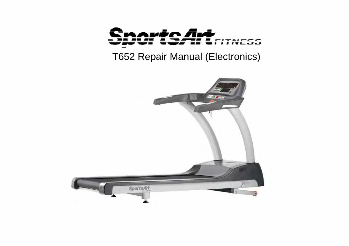
T652 Repair Manual (Electronics)
Transcript of T652 Treadmill Electronics Repair Manual - SportsArt
T652 Repair Manual (Electronics)
Table of Contents 1-1-1. Product Illustration – T652 1-2-1. Display – T652 1-3-1. Component Placement – T652 Display 1-3-2. Component Placement – T652 Drive Compartment 1-4-1. Block Diagram of Electronic Components – T652 1-5-1. Cable Connections - T652 Display 1-5-2. Cable Connections - T652 EAC Drive Board 1-6-1. LED Indicators - T652 Display Board 1-6-2. LED Indicators - T652 Drive Board 1-7-1. Electronic Specifications - T652 2-1-1. Electronic Component Troubleshooting Chart - T652 3-1-1. Troubleshooting – Safety Key Malfunction - T652 3-2-1. Troubleshooting – Unit Will Not Start - T652 3-3-1. Troubleshooting – No Telemetry Heart Rate - T652 3-4-1. Troubleshooting – Key Malfunction – Soft Keys - T652 3-5-1. Troubleshooting – Key Malfunction – Display Keys - T652 3-6-1. Troubleshooting – Incline Operation Malfunction - T652 3-7-1. Troubleshooting – Contact Heart Rate Malfunction - T652 3-8-1. Troubleshooting – Fuse Breaks at Start – T652 3-8-2. Troubleshooting – Fuse Breaks at Speed - T652 3-8-3. Troubleshooting – Fuse Breaks in Use - T652 3-9-1. Troubleshooting – ERROR_1_1_T652 3-9-2. Troubleshooting – ERROR_1_2_T652 3-9-3. Troubleshooting – ERR0R_1_3_T652 3-10-1. Troubleshooting – ERROR_2_1_T652 3-11-1. Troubleshooting – ERROR_3_1_T652 3-12-1. Troubleshooting – ERROR_8_1_T652 3-12-2. Troubleshooting – ERROR_8_2_T652 3-13-1. Troubleshooting – SERVICE NEEDED-APPLY LUBE-T652 3-14-1. Other - KPH/MPH, distance, time, display/drive board program versions - T652 3-15-1. Other – Error Message Chart - T652
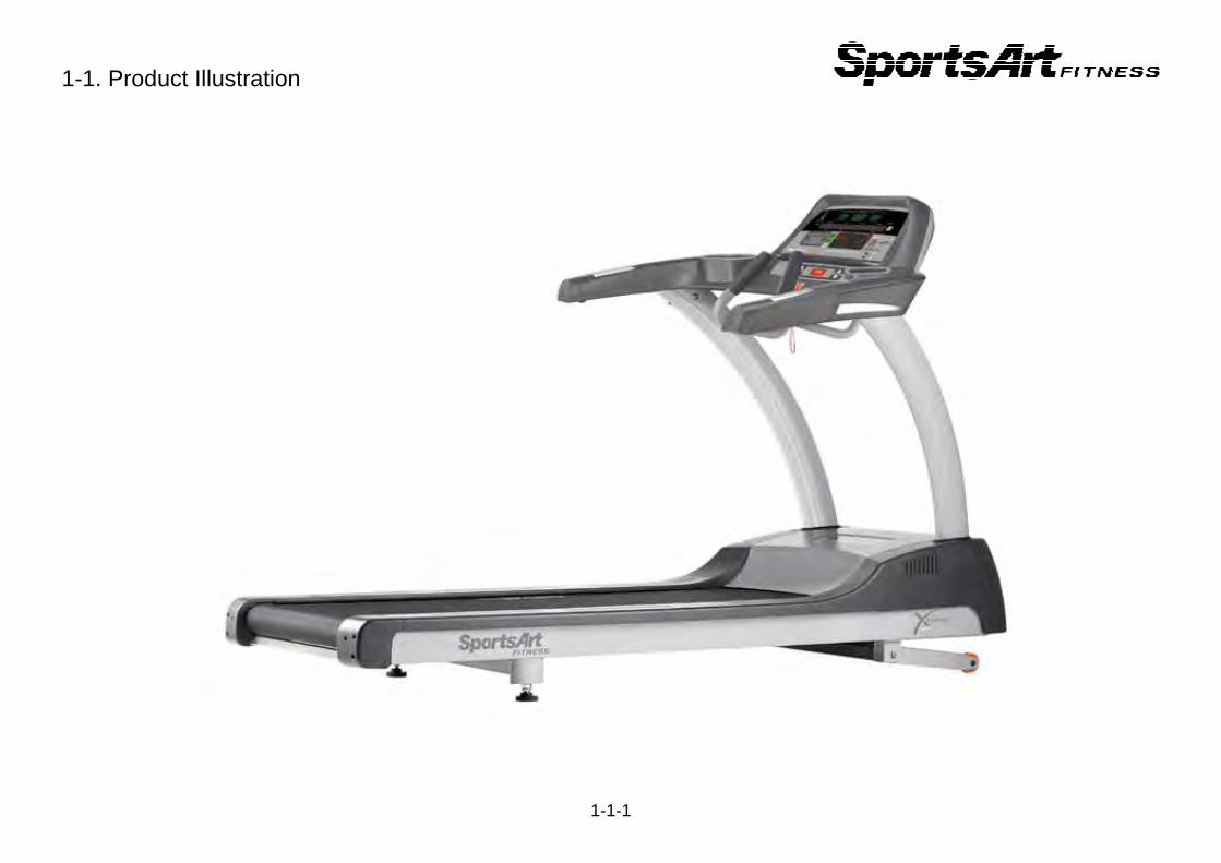
1-1. Product Illustration
1-1-1
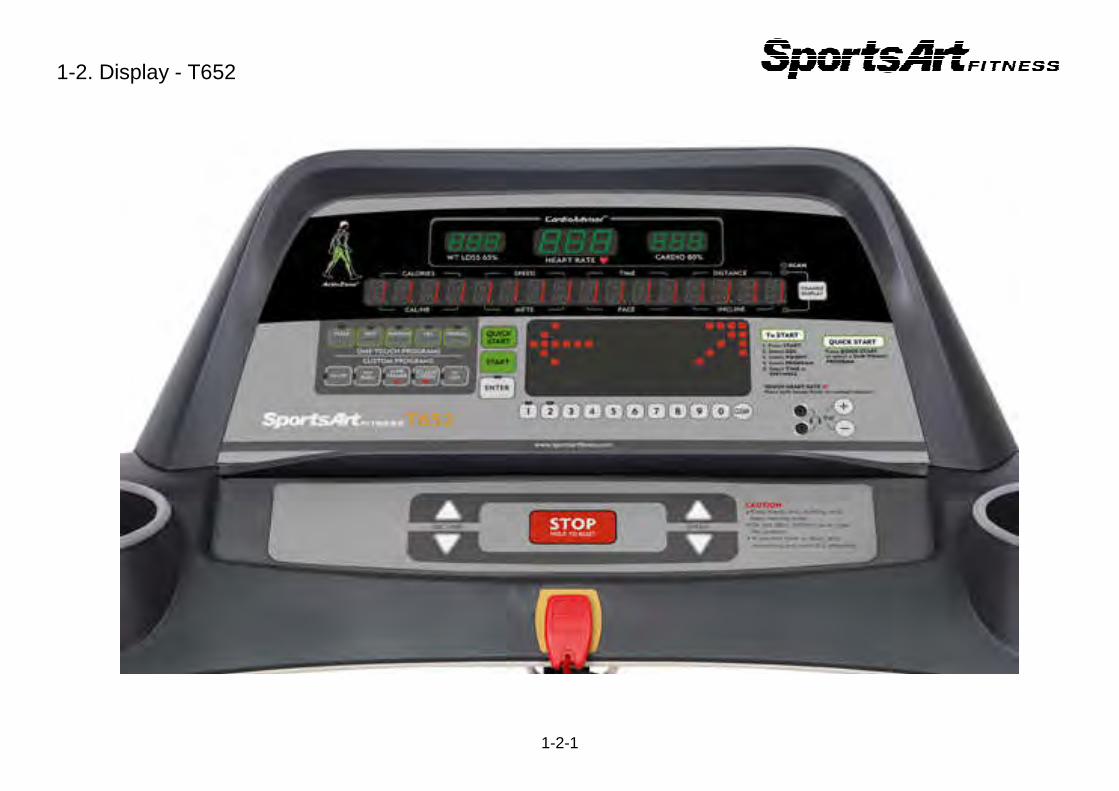
1-2. Display - T652
1-2-1
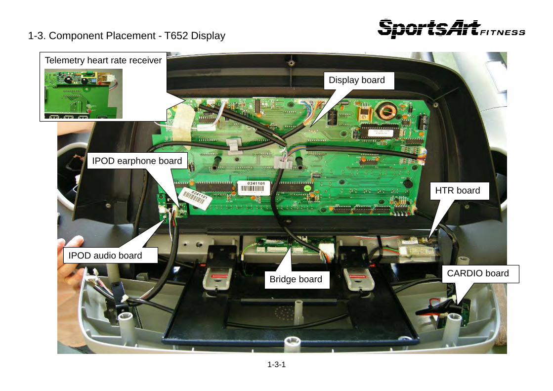
1-3. Component Placement - T652 Display
1-3-1
HTR board
Display board
Bridge board
IPOD earphone board
IPOD audio board
Telemetry heart rate receiver
CARDIO board
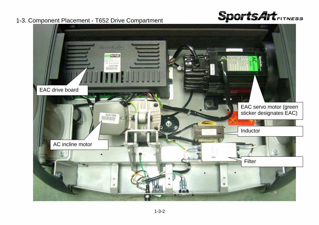
1-3. Component Placement - T652 Drive Compartment
1-3-2
EAC drive board
AC incline motor
Filter
EAC servo motor (green sticker designates EAC)
Inductor
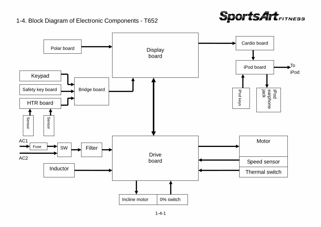
1-4. Block Diagram of Electronic Components - T652
1-4-1
Display board
Drive board
Motor
Speed sensor
Thermal switch
Incline motor 0% switch
Inductor
Filter
Polar board
Bridge board
HTR board
Safety key board
Keypad
Polar board Cardio board
iPod board
iPod keys
iPod
earphone jack
SW Fuse
AC1
AC2
To
iPod
Sensor
Sensor
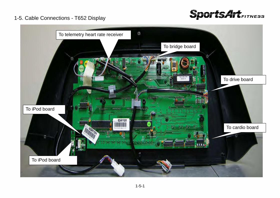
1-5. Cable Connections - T652 Display
1-5-1
To cardio board
To drive board
To bridge board
To telemetry heart rate receiver
To iPod board
To iPod board
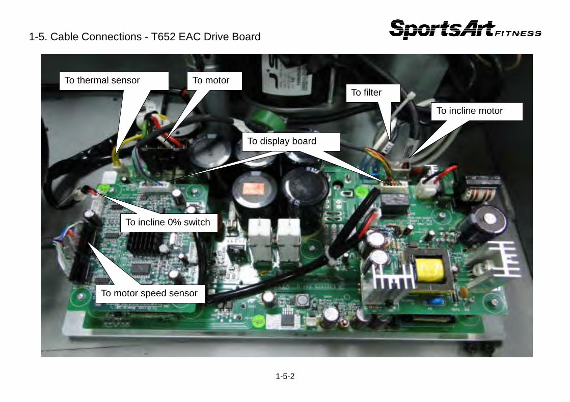
1-5. Cable Connections - T652 EAC Drive Board
1-5-2
To motor speed sensor
To thermal sensor
接至電子表組
To filter
To display board
To motor
To incline 0% switch
To incline motor

1-6. Indicator LEDs - T652 Display Board
1-6-1
Power indicator LED � Indicates display is receiving power.
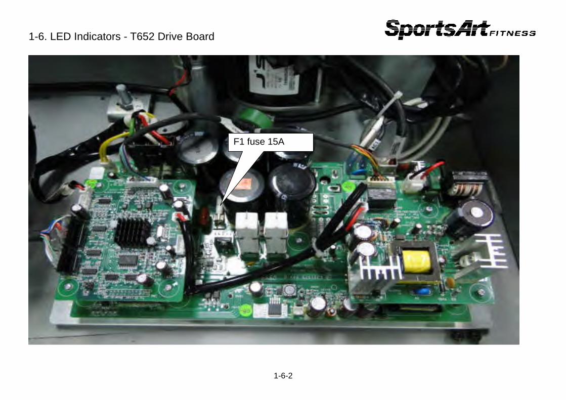
1-6. LED Indicators - T652 Drive Board
1-6-2
F1 fuse 15A
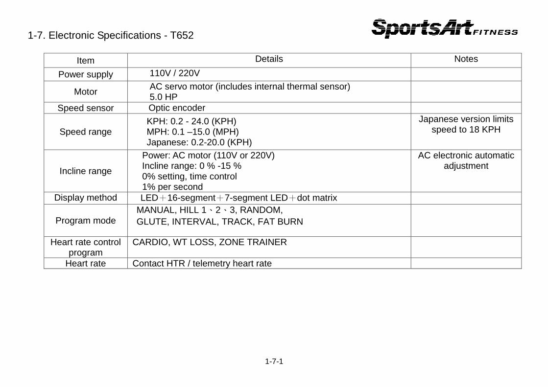
1-7. Electronic Specifications - T652
Item Details Notes
Power supply 110V / 220V
Motor AC servo motor (includes internal thermal sensor) 5.0 HP
Speed sensor Optic encoder
Speed range KPH: 0.2 - 24.0 (KPH) MPH: 0.1 –15.0 (MPH) Japanese: 0.2-20.0 (KPH)
Japanese version limits speed to 18 KPH
Incline range
Power: AC motor (110V or 220V) Incline range: 0 % -15 % 0% setting, time control 1% per second
AC electronic automatic adjustment
Display method LED+16-segment+7-segment LED+dot matrix
Program mode MANUAL, HILL 1、2、3, RANDOM, GLUTE, INTERVAL, TRACK, FAT BURN
Heart rate control program
CARDIO, WT LOSS, ZONE TRAINER
Heart rate Contact HTR / telemetry heart rate
1-7-1
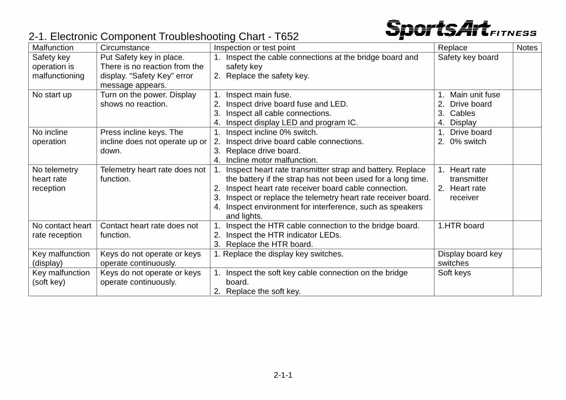
2-1. Electronic Component Troubleshooting Chart - T652 Malfunction Circumstance Inspection or test point Replace Notes Safety key operation is malfunctioning
Put Safety key in place. There is no reaction from the display. “Safety Key” error message appears.
1. Inspect the cable connections at the bridge board and safety key
2. Replace the safety key.
Safety key board
No start up Turn on the power. Display shows no reaction.
1. Inspect main fuse. 2. Inspect drive board fuse and LED. 3. Inspect all cable connections. 4. Inspect display LED and program IC.
1. Main unit fuse 2. Drive board 3. Cables 4. Display
No incline operation
Press incline keys. The incline does not operate up or down.
1. Inspect incline 0% switch. 2. Inspect drive board cable connections. 3. Replace drive board. 4. Incline motor malfunction.
1. Drive board 2. 0% switch
No telemetry heart rate reception
Telemetry heart rate does not function.
1. Inspect heart rate transmitter strap and battery. Replace the battery if the strap has not been used for a long time.
2. Inspect heart rate receiver board cable connection. 3. Inspect or replace the telemetry heart rate receiver board. 4. Inspect environment for interference, such as speakers
and lights.
1. Heart rate transmitter
2. Heart rate receiver
No contact heart rate reception
Contact heart rate does not function.
1. Inspect the HTR cable connection to the bridge board. 2. Inspect the HTR indicator LEDs. 3. Replace the HTR board.
1.HTR board
Key malfunction (display)
Keys do not operate or keys operate continuously.
1. Replace the display key switches. Display board key switches
Key malfunction (soft key)
Keys do not operate or keys operate continuously.
1. Inspect the soft key cable connection on the bridge board.
2. Replace the soft key.
Soft keys
2-1-1
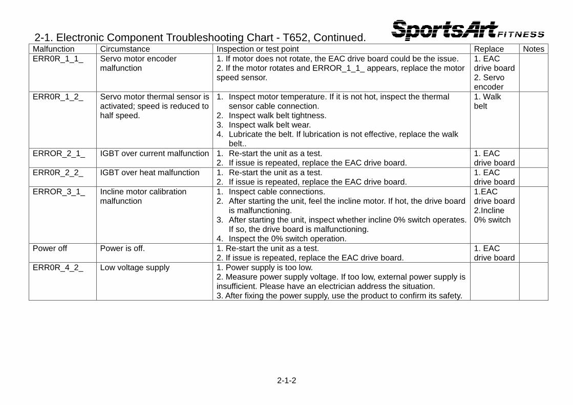
2-1. Electronic Component Troubleshooting Chart - T652, Continued. Malfunction Circumstance Inspection or test point Replace Notes ERR0R_1_1_ Servo motor encoder
malfunction 1. If motor does not rotate, the EAC drive board could be the issue. 2. If the motor rotates and ERROR_1_1_ appears, replace the motor speed sensor.
1. EAC drive board 2. Servo encoder
ERR0R_1_2_ Servo motor thermal sensor is activated; speed is reduced to half speed.
1. Inspect motor temperature. If it is not hot, inspect the thermal sensor cable connection.
2. Inspect walk belt tightness. 3. Inspect walk belt wear. 4. Lubricate the belt. If lubrication is not effective, replace the walk
belt..
1. Walk belt
ERROR_2_1_ IGBT over current malfunction 1. Re-start the unit as a test. 2. If issue is repeated, replace the EAC drive board.
1. EAC drive board
ERR0R_2_2_ IGBT over heat malfunction 1. Re-start the unit as a test. 2. If issue is repeated, replace the EAC drive board.
1. EAC drive board
ERROR_3_1_ Incline motor calibration malfunction
1. Inspect cable connections. 2. After starting the unit, feel the incline motor. If hot, the drive board
is malfunctioning. 3. After starting the unit, inspect whether incline 0% switch operates.
If so, the drive board is malfunctioning. 4. Inspect the 0% switch operation.
1.EAC drive board 2.Incline 0% switch
Power off Power is off. 1. Re-start the unit as a test. 2. If issue is repeated, replace the EAC drive board.
1. EAC drive board
ERR0R_4_2_ Low voltage supply 1. Power supply is too low. 2. Measure power supply voltage. If too low, external power supply is insufficient. Please have an electrician address the situation. 3. After fixing the power supply, use the product to confirm its safety.
2-1-2
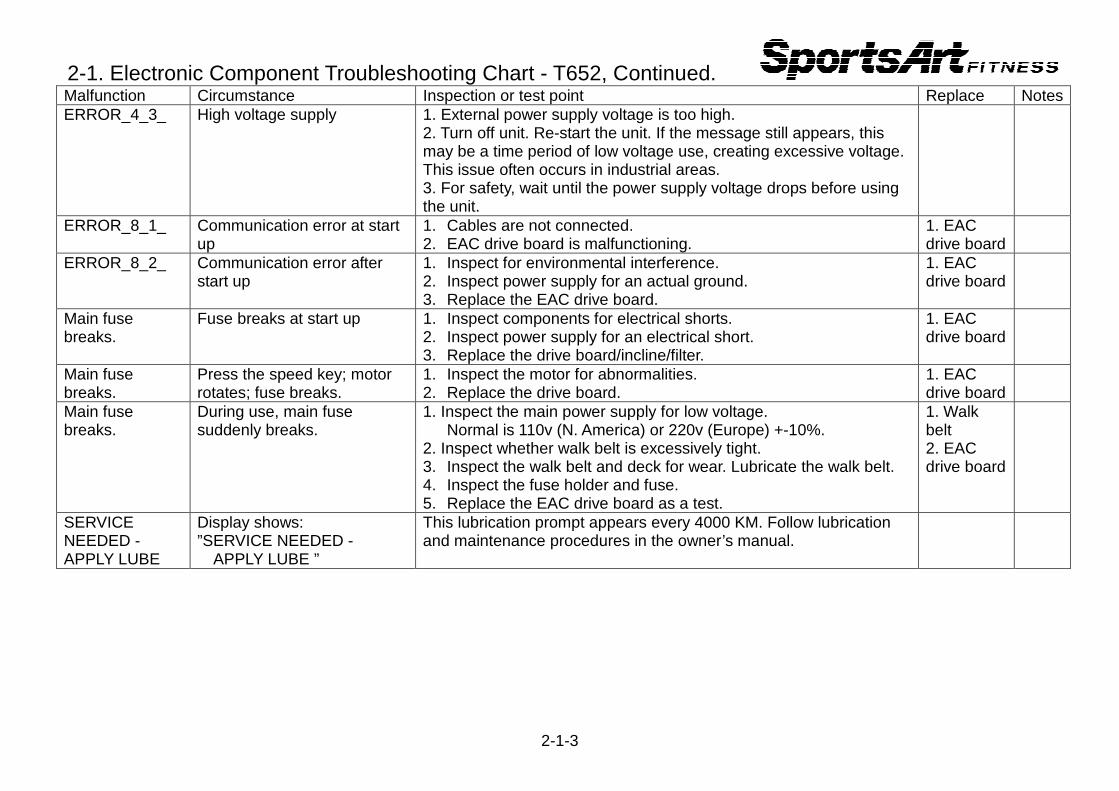
2-1. Electronic Component Troubleshooting Chart - T652, Continued. Malfunction Circumstance Inspection or test point Replace Notes ERROR_4_3_ High voltage supply 1. External power supply voltage is too high.
2. Turn off unit. Re-start the unit. If the message still appears, this may be a time period of low voltage use, creating excessive voltage. This issue often occurs in industrial areas. 3. For safety, wait until the power supply voltage drops before using the unit.
ERROR_8_1_ Communication error at start up
1. Cables are not connected. 2. EAC drive board is malfunctioning.
1. EAC drive board
ERROR_8_2_ Communication error after start up
1. Inspect for environmental interference. 2. Inspect power supply for an actual ground. 3. Replace the EAC drive board.
1. EAC drive board
Main fuse breaks.
Fuse breaks at start up 1. Inspect components for electrical shorts. 2. Inspect power supply for an electrical short. 3. Replace the drive board/incline/filter.
1. EAC drive board
Main fuse breaks.
Press the speed key; motor rotates; fuse breaks.
1. Inspect the motor for abnormalities. 2. Replace the drive board.
1. EAC drive board
Main fuse breaks.
During use, main fuse suddenly breaks.
1. Inspect the main power supply for low voltage. Normal is 110v (N. America) or 220v (Europe) +-10%.
2. Inspect whether walk belt is excessively tight. 3. Inspect the walk belt and deck for wear. Lubricate the walk belt. 4. Inspect the fuse holder and fuse. 5. Replace the EAC drive board as a test.
1. Walk belt 2. EAC drive board
SERVICE NEEDED - APPLY LUBE
Display shows: ”SERVICE NEEDED - APPLY LUBE ”
This lubrication prompt appears every 4000 KM. Follow lubrication and maintenance procedures in the owner’s manual.
2-1-3

2-1. Electronic Component Troubleshooting Chart - T652, Continued. Malfunction Circumstance Inspection or test point Replace Notes Show total distance
Press the <CHANGE> key three seconds to see KM/Miles, total distance, total time, display IC version, drive board IC version.
Contact HTR heart rate malfunction
FOR ACCURATE HR, HOLD SENSORS FIRMLY WHILE WALKING
1. Hold contact heart rate grips firmly to test HTR function.
2. If you are already holding grips firmly, inspect the HTR contact wire connections.
2-1-4
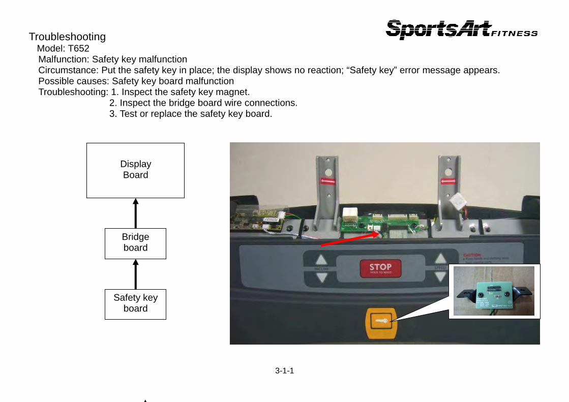
Troubleshooting Model: T652 Malfunction: Safety key malfunction Circumstance: Put the safety key in place; the display shows no reaction; “Safety key” error message appears. Possible causes: Safety key board malfunction Troubleshooting: 1. Inspect the safety key magnet. 2. Inspect the bridge board wire connections. 3. Test or replace the safety key board.
3-1-1
Display Board
Bridge board
Safety key board

Troubleshooting Model: T652 Malfunction: Unit will not start operating. Circumstance: Turn POWER ON; the display does not light. Possible cause: Incoming power issue; component failure. Troubleshooting: 1. Inspect the main fuse and power switch. 2. Inspect all cable connections. 3. Inspect drive board power LED. Or replace the drive board as a test. 4. Inspect the display power LED and main IC.
3-2-1
Drive board
Display board
Filter Power
switch
FUSE
AC1
AC2
Fuse and power switch
Filter
EAC drive board組
Cables
Main program IC
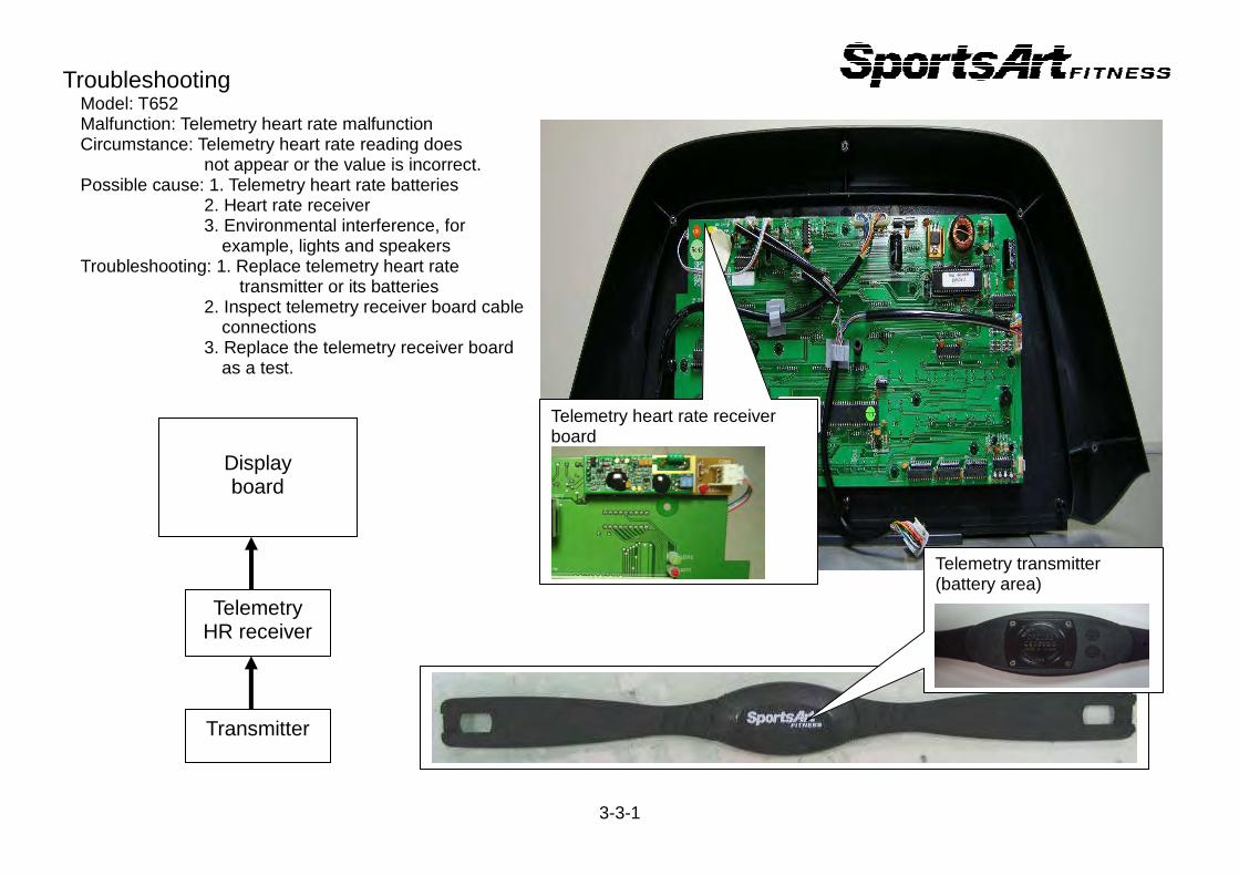
Troubleshooting Model: T652 Malfunction: Telemetry heart rate malfunction Circumstance: Telemetry heart rate reading does not appear or the value is incorrect. Possible cause: 1. Telemetry heart rate batteries 2. Heart rate receiver 3. Environmental interference, for example, lights and speakers Troubleshooting: 1. Replace telemetry heart rate transmitter or its batteries 2. Inspect telemetry receiver board cable connections 3. Replace the telemetry receiver board as a test.
3-3-1
Telemetry HR receiver
Display board
Transmitter
Telemetry heart rate receiver board
Telemetry transmitter (battery area)
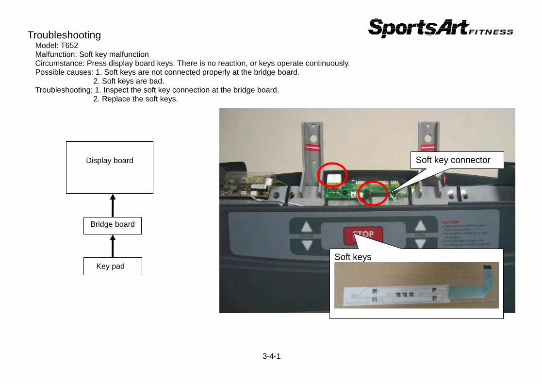
Troubleshooting Model: T652 Malfunction: Soft key malfunction Circumstance: Press display board keys. There is no reaction, or keys operate continuously. Possible causes: 1. Soft keys are not connected properly at the bridge board. 2. Soft keys are bad. Troubleshooting: 1. Inspect the soft key connection at the bridge board. 2. Replace the soft keys.
3-4-1
Bridge board
Display board
Key pad Soft keys
Soft key connector

Troubleshooting Model: T652 Malfunction: Key malfunction – display keys Circumstance: Press display keys; there is no reaction; Or keys operate continuously. Possible causes: 1. Display key switch malfunction: SW1-SW25. 2. Key cushions are out of place. Troubleshooting: 1. Inspect key cushions. 2. Replace display key switches.
3-5-1
SW1-SW13 SW25
Display board
(CPU)
SW14-SW2
SW14-SW24
SW1-SW13
Key cushions
SW25
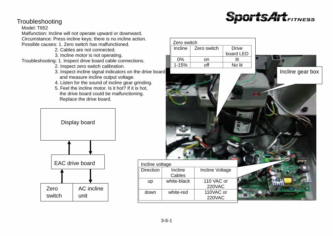
Troubleshooting Model: T652 Malfunction: Incline will not operate upward or downward. Circumstance: Press incline keys; there is no incline action. Possible causes: 1. Zero switch has malfunctioned. 2. Cables are not connected. 3. Incline motor is not operating. Troubleshooting: 1. Inspect drive board cable connections. 2. Inspect zero switch calibration. 3. Inspect incline signal indicators on the drive board and measure incline output voltage. 4. Listen for the sound of incline gear grinding. 5. Feel the incline motor. Is it hot? If it is hot, the drive board could be malfunctioning. Replace the drive board.
3-6-1
EAC drive board
Display board
Zero switch
AC incline unit
Incline gear box
Zero switch Incline Zero switch Drive
board LED 0% on lit
1-15% off No lit
Incline voltage Direction Incline
Cables Incline Voltage
up white-black 110 VAC or 220VAC
down white-red 110VAC or 220VAC
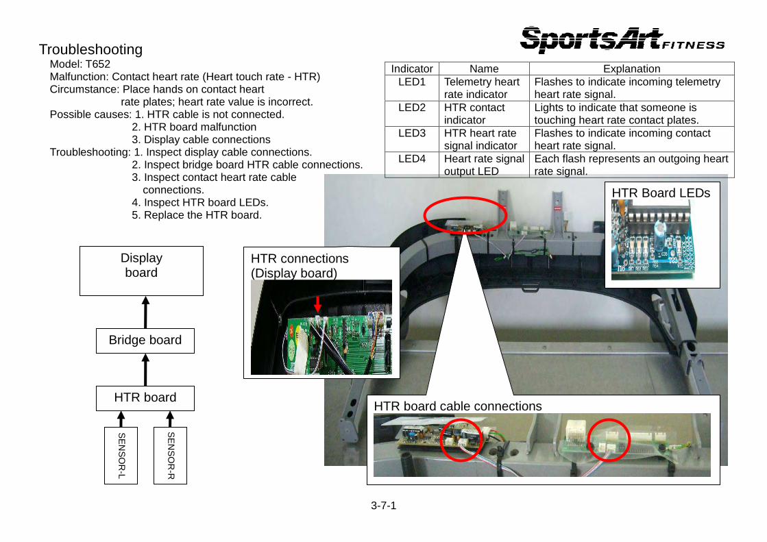
Troubleshooting Model: T652 Malfunction: Contact heart rate (Heart touch rate - HTR)
Circumstance: Place hands on contact heart rate plates; heart rate value is incorrect. Possible causes: 1. HTR cable is not connected. 2. HTR board malfunction 3. Display cable connections Troubleshooting: 1. Inspect display cable connections. 2. Inspect bridge board HTR cable connections. 3. Inspect contact heart rate cable connections. 4. Inspect HTR board LEDs. 5. Replace the HTR board.
3-7-1
Bridge board
Display board
HTR board
SE
NS
OR
-L
SE
NS
OR
-R
HTR board cable connections
HTR Board LEDs
Indicator Name Explanation LED1 Telemetry heart
rate indicator Flashes to indicate incoming telemetry heart rate signal.
LED2 HTR contact indicator
Lights to indicate that someone is touching heart rate contact plates.
LED3 HTR heart rate signal indicator
Flashes to indicate incoming contact heart rate signal.
LED4 Heart rate signal output LED
Each flash represents an outgoing heart rate signal.
HTR connections (Display board)
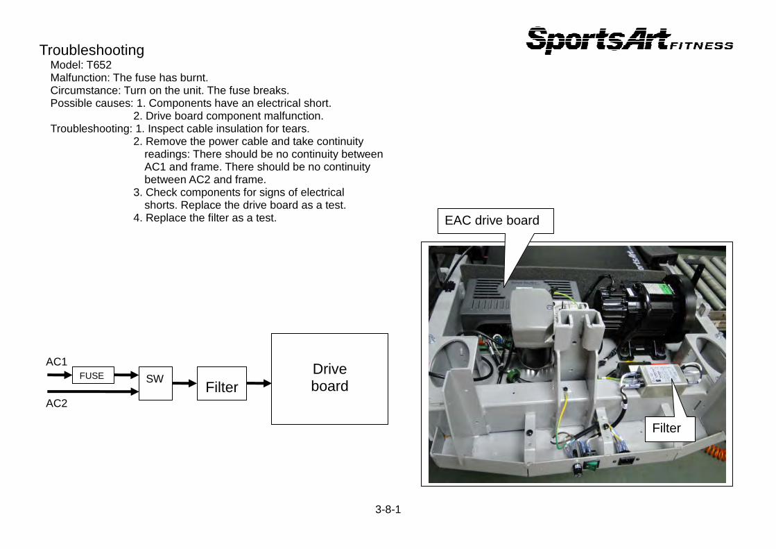
Troubleshooting Model: T652 Malfunction: The fuse has burnt.
Circumstance: Turn on the unit. The fuse breaks. Possible causes: 1. Components have an electrical short. 2. Drive board component malfunction. Troubleshooting: 1. Inspect cable insulation for tears. 2. Remove the power cable and take continuity readings: There should be no continuity between AC1 and frame. There should be no continuity between AC2 and frame. 3. Check components for signs of electrical shorts. Replace the drive board as a test. 4. Replace the filter as a test.
3-8-1
Drive board
Filter
SW FUSE
AC1
AC2
Filter
EAC drive board
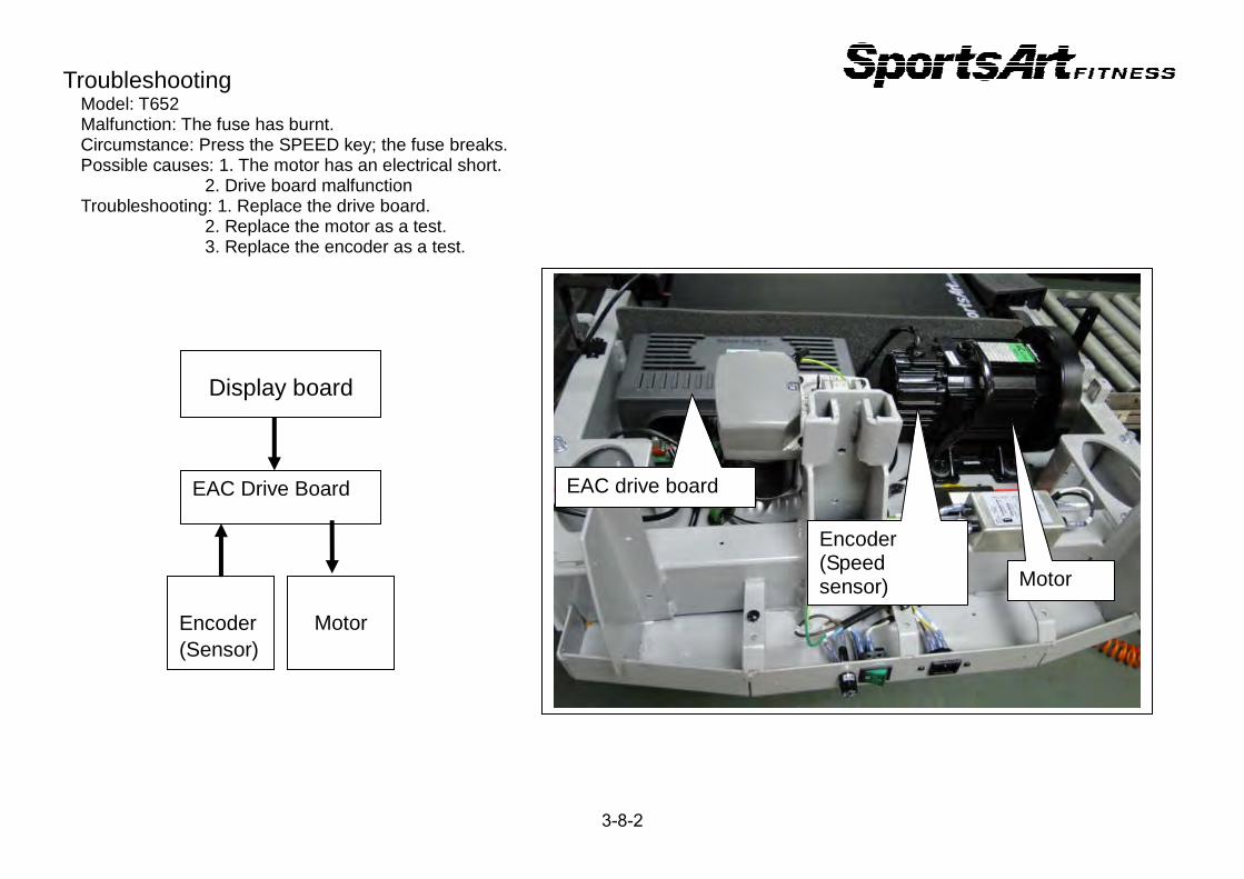
Troubleshooting Model: T652 Malfunction: The fuse has burnt.
Circumstance: Press the SPEED key; the fuse breaks. Possible causes: 1. The motor has an electrical short. 2. Drive board malfunction Troubleshooting: 1. Replace the drive board. 2. Replace the motor as a test. 3. Replace the encoder as a test.
3-8-2
EAC Drive Board
Display board
Encoder (Sensor)
Motor
EAC drive board
Motor
Encoder (Speed sensor)
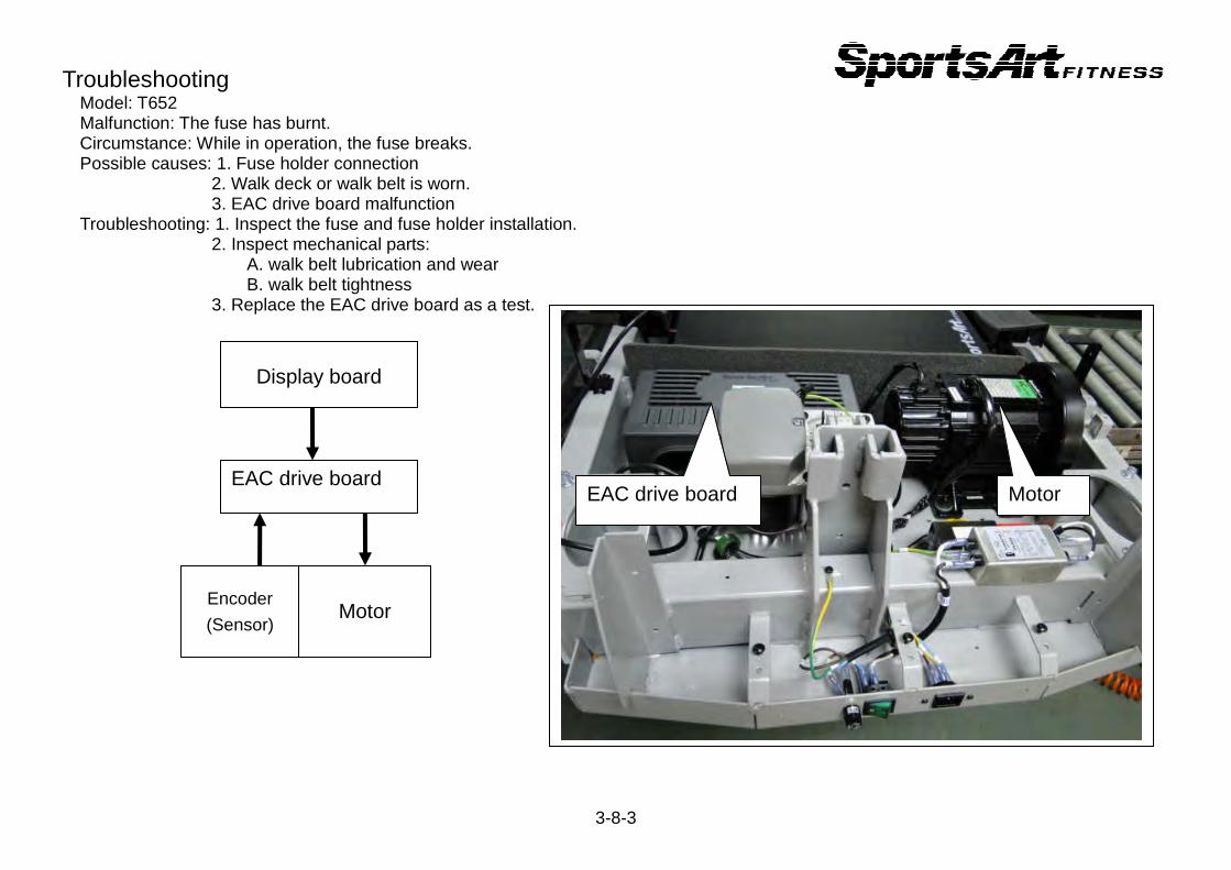
Troubleshooting Model: T652 Malfunction: The fuse has burnt.
Circumstance: While in operation, the fuse breaks. Possible causes: 1. Fuse holder connection 2. Walk deck or walk belt is worn. 3. EAC drive board malfunction Troubleshooting: 1. Inspect the fuse and fuse holder installation. 2. Inspect mechanical parts: A. walk belt lubrication and wear B. walk belt tightness 3. Replace the EAC drive board as a test.
3-8-3
EAC drive board
Display board
Encoder
(Sensor)
Motor
EAC drive board Motor
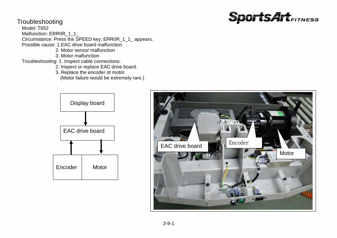
Troubleshooting Model: T652 Malfunction: ERR0R_1_1_
Circumstance: Press the SPEED key; ERR0R_1_1_ appears. Possible cause: 1.EAC drive board malfunction 2. Motor sensor malfunction 3. Motor malfunction Troubleshooting: 1. Inspect cable connections. 2. Inspect or replace EAC drive board. 3. Replace the encoder or motor. (Motor failure would be extremely rare.)
3-9-1
EAC drive board
Display board
Encoder
Motor
EAC drive board Motor
Encoder
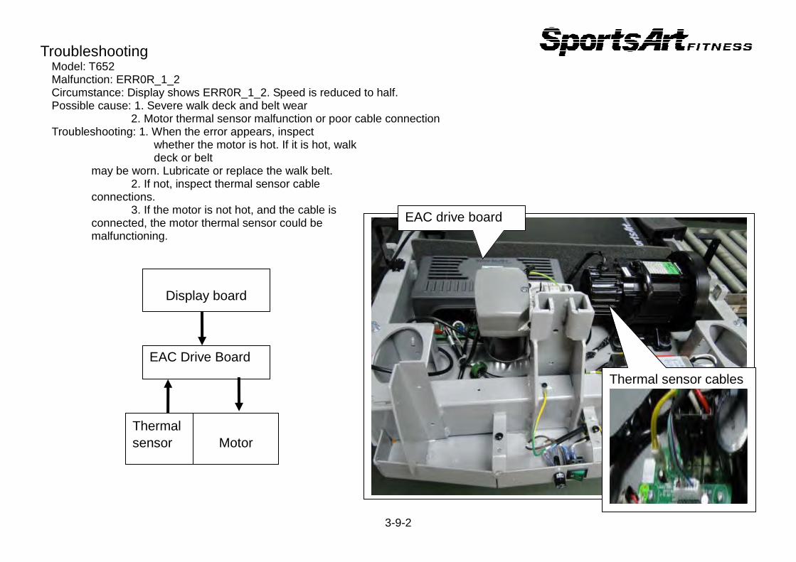
Troubleshooting Model: T652 Malfunction: ERR0R_1_2 Circumstance: Display shows ERR0R_1_2. Speed is reduced to half.
Possible cause: 1. Severe walk deck and belt wear 2. Motor thermal sensor malfunction or poor cable connection
Troubleshooting: 1. When the error appears, inspect whether the motor is hot. If it is hot, walk
deck or belt may be worn. Lubricate or replace the walk belt. 2. If not, inspect thermal sensor cable connections. 3. If the motor is not hot, and the cable is connected, the motor thermal sensor could be malfunctioning.
3-9-2
EAC Drive Board
Display board
Thermal sensor
Motor
EAC drive board
Thermal sensor cables
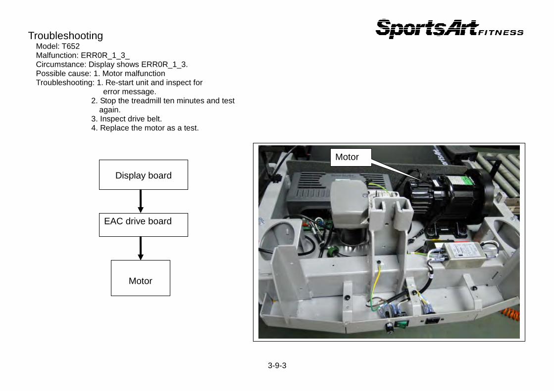
Troubleshooting Model: T652 Malfunction: ERR0R_1_3_
Circumstance: Display shows ERR0R_1_3. Possible cause: 1. Motor malfunction Troubleshooting: 1. Re-start unit and inspect for error message. 2. Stop the treadmill ten minutes and test again. 3. Inspect drive belt. 4. Replace the motor as a test.
3-9-3
EAC drive board
Display board
Motor
Motor
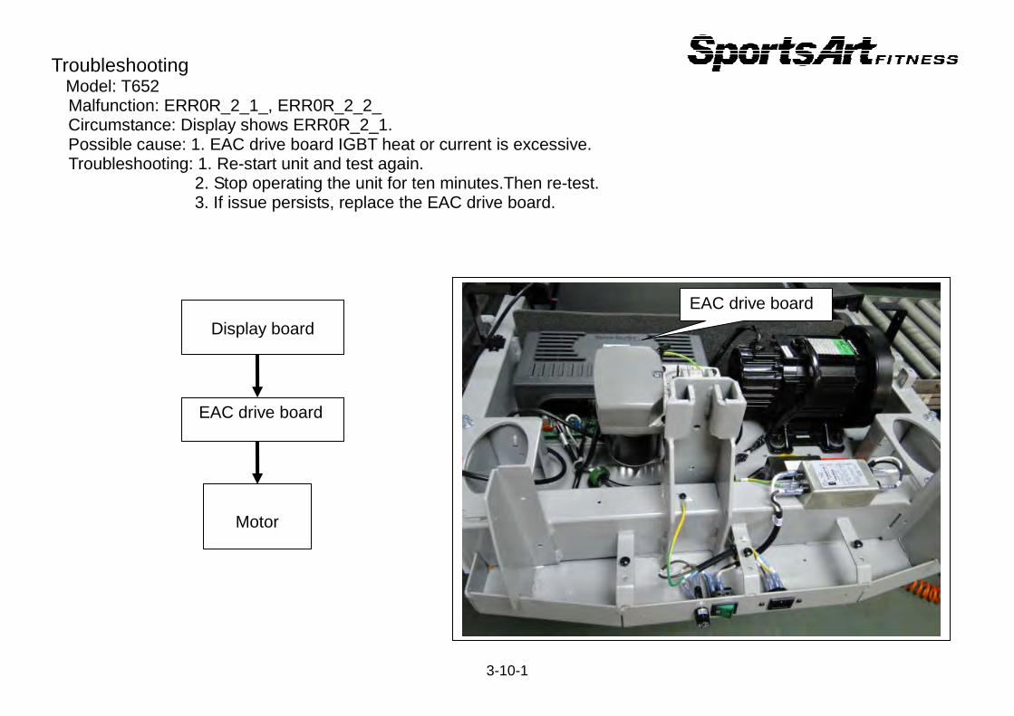
Troubleshooting Model: T652 Malfunction: ERR0R_2_1_, ERR0R_2_2_
Circumstance: Display shows ERR0R_2_1. Possible cause: 1. EAC drive board IGBT heat or current is excessive. Troubleshooting: 1. Re-start unit and test again. 2. Stop operating the unit for ten minutes.Then re-test. 3. If issue persists, replace the EAC drive board.
3-10-1
EAC drive board
Display board
Motor
EAC drive board
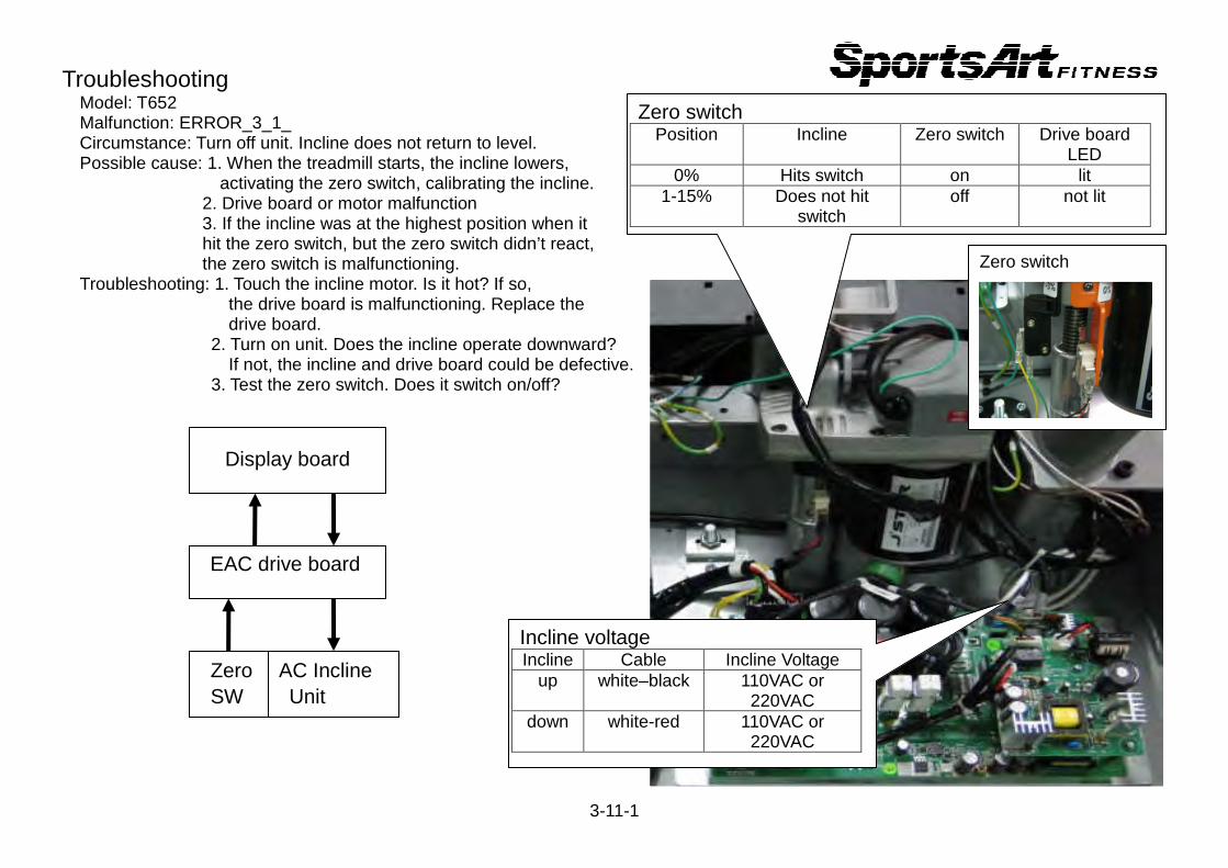
Troubleshooting Model: T652 Malfunction: ERROR_3_1_
Circumstance: Turn off unit. Incline does not return to level. Possible cause: 1. When the treadmill starts, the incline lowers, activating the zero switch, calibrating the incline. 2. Drive board or motor malfunction 3. If the incline was at the highest position when it hit the zero switch, but the zero switch didn’t react, the zero switch is malfunctioning. Troubleshooting: 1. Touch the incline motor. Is it hot? If so, the drive board is malfunctioning. Replace the drive board. 2. Turn on unit. Does the incline operate downward? If not, the incline and drive board could be defective. 3. Test the zero switch. Does it switch on/off?
3-11-1
EAC drive board
Display board
Zero SW
AC Incline Unit
Zero switch
Zero switch Position Incline Zero switch Drive board
LED 0% Hits switch on lit
1-15% Does not hit switch
off not lit
Incline voltage Incline Cable Incline Voltage
up white–black 110VAC or 220VAC
down white-red 110VAC or 220VAC
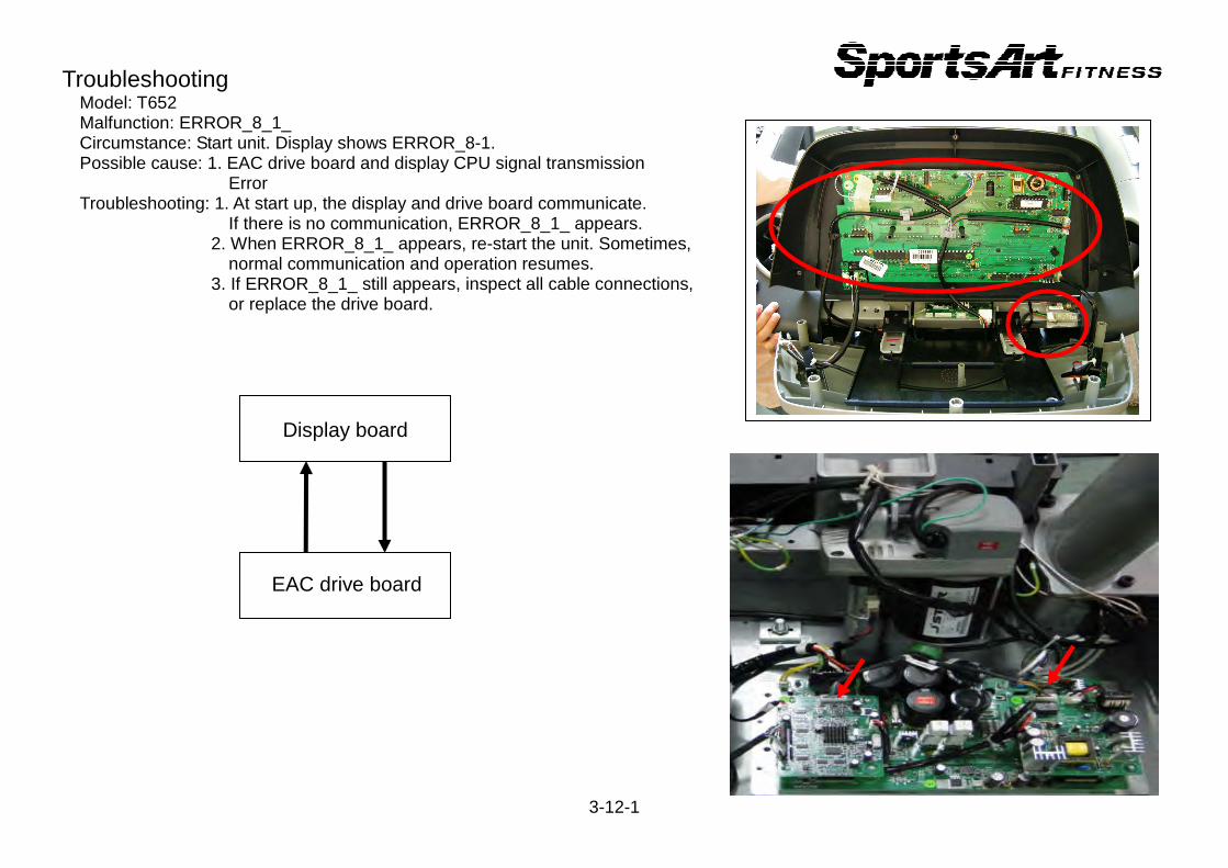
Troubleshooting Model: T652 Malfunction: ERROR_8_1_
Circumstance: Start unit. Display shows ERROR_8-1. Possible cause: 1. EAC drive board and display CPU signal transmission Error Troubleshooting: 1. At start up, the display and drive board communicate. If there is no communication, ERROR_8_1_ appears. 2. When ERROR_8_1_ appears, re-start the unit. Sometimes, normal communication and operation resumes. 3. If ERROR_8_1_ still appears, inspect all cable connections, or replace the drive board.
3-12-1
EAC drive board
Display board

Troubleshooting Model: T652 Malfunction: ERROR_8_2_
Circumstance: In operation, the display shows ERROR_8_2_. Possible cause: 1. Interference disrupts communication between the display and EAC drive board. Troubleshooting: 1. Inspect cable connections between the display and drive boards. 2. When this error appears, re-start the unit. Sometimes, re-starting the unit restores normal communication and operation. 3. If re-starting the unit does not eliminate ERROR_8_2_, replace the EAC drive board.
3-12-2
EAC drive board
Display board
Troubleshooting Model: T652 Malfunction: SERVICE NEEDED-APPLY LUBE Circumstance: “SERVICE NEEDED-APPLY LUBE” appears. Unit stops operating. Possible cause: Every 4000 km, the display notifies the user that it is time to lubricate the walk belt. Troubleshooting: 1. Display shows “SERVICE NEEDED-APPLY LUBE”. 2. Simultaneously press <0>+INCLINE<▲>+INCLINE<▼> for two seconds to enter lubrication mode. Time window counts down: 3,2,1. Speed window shows 2.0 kph (or 1.3 mph). The walk belt starts to rotate. 3. Hold the applicator tube in front of the rear roller. Squeeze the lubricant into the applicator tube. Allow the unit to
operate for ten minutes, letting the lubricant drip onto the bottom side of the walk belt. 4. After ten minutes, press the <STOP> key to exit the lubrication mode. Re-start the unit. Distance memory will be
Cleared and then start accruing again. 5. After applying the lubricant, use the unit for ten minutes to disperse the lubricant.
3-13-1

Other Model: T652 Item: How to select KPH/MPH units of measure and view distance, time, and display/drive board program versions. Method: 1. Press the <CHANGE> key three seconds to enter the user parameter mode. 2. KPH/MPH setting Display shows “UNIT-MPH” (Imperial standard) or “UNIT-KPH” (Metric standard). Press the INCLINE<▲> or <▼> key to toggle between MPH and KPH settings. Press the <ENTER> key to confirm your choice. 3. Distance Display shows total distance as DIST-XXXXXXKM. Press the <ENTER> key to proceed to the next view.
4. Time Display shows total time as TIME-XXXXXXHOUR. Press the <ENTER> key to proceed to the next view. 5. Display board program version Display shows the display board IC version, for example, CTL T650-1A. Press the <ENTER> key to proceed
to the next view. 6. Drive board program version Display shows the drive board IC version, for example, DRV SERVO-1A. Press the <ENTER> key to exit the user parameter setting.
3-14-1
Other Model: T652 Item: Error Message Chart
ERROR_1_1_ : Servo motor encoder abnormality; Re-start unit. ERROR_1_2_ : Servo motor high temperature warning. Unit operates at half speed. ERROR_1_3_ : Servo motor excessive current warning. Re-start unit. ERROR_2_1_ : IGBT excessive current warning. Wait 10 seconds for unit recovery. ERROR_2_2_ : IGBT excessive heat. Unit operates at half speed. ERROR_3_1_ : Incline motor calibration abnormality. POWER OFF : Power switch: off. ERROR_4_2_ : Power supply voltage is too low. Re-start unit after power supply stabilizes. ERROR_4_3_ : Power voltage is too high. Re-start unit after power supply stabilizes. ERROR_8_1_ : Communication abnormality at start up.
ERROR_8_2_ : Communication abnormality during operation.
3-15-1
![T652 - 4062[1]](https://static.fdocuments.in/doc/165x107/553ca0d15503461c478b4a74/t652-40621.jpg)