6287 ULTRA Ž
202
AGILE 875 Alfred Nobel Drive Hercules, CA 94547-1899 TEL (510) 724-1600 TEL (800) 538-1634 FAX (510) 724-9624 Customer Support: FAX (510) 724-2222 E-MAIL [email protected] 6287 ULTRA ™ Users Manual POWER CU SIGNAL ALT HOST PRINTER READY HOLD PRINT DATA OUT SCS CHECK TEST KEY DOWN RESET PA1 PA2 LINE FEED HOLD PRINT TEST CANCEL FORM FEED ENABLE PRINT 6287 ULTRA ™ Printer Interface Controller
Transcript of 6287 ULTRA Ž
AGILE875 Alfred Nobel Drive
Hercules, CA 94547-1899
TEL (510) 724-1600 � TEL (800) 538-1634 � FAX (510) 724-9624Customer Support: FAX (510) 724-2222 � E-MAIL [email protected]
6287 ULTRA�
User�s Manual
POWERCU
SIGNALALT
HOSTPRINTER READY
HOLD PRINT
DATA OUT SCS CHECK TEST
KEY DOWN
RESET PA1 PA2 LINE FEED
HOLD PRINT
TEST CANCEL FORM FEED
ENABLE PRINT6287
ULTRA™
Printer Interface Controller

Page ii 6287 ULTRA User�s Manual
Copyright Information
© 1995 AGILE
All rights reserved. Copyright protection includes all forms and matters ofcopyrightable material and information now allowed by statutory orjudicial law or hereinafter granted.
AGILE is a registered trademark of AGILE. 6287 ULTRA and all otherAGILE products mentioned in this publication are trademarks of AGILE.
IBM and all IBM products mentioned in this publication are registeredtrademarks of International Business Machines, Inc.
Xerox, 2700, 3700, 4010, 4011, 4030, 4045, 4197, 4213, 4220, 4235,4700 and all other Xerox products mentioned in this publication aretrademarks of Xerox Corporation.
Hewlett-Packard, LaserJet II, IID, IIID, IIISi, 4, 4Si and all other HPproducts mentioned in this publication are trademarks of the Hewlett-Packard Company.
All other trademarks appearing in this publication are owned by theirrespective companies.
Release Notes
This document was printed in December 1995 and describes the AGILE6287 ULTRA firmware version 46.00 and later.
Printed in the United States of America.
Fill in for future reference:
6287 ULTRA Purchase Date: _______________________
6287 ULTRA Serial Number: _______________________

Page iii
About AGILE
In 1978 �IBM� and the word �compatible� were rarely found together, butIBM�s mainframe customers wanted a less expensive, more flexibleprinting solution than IBM offered them. They wanted value, performanceand features that only ASCII printers could provide. They wanted freedomof choice.
This market need prompted Robert Torrey, then Director of Engineeringfor AGILE, to develop a bridge between popular ASCII printers and theIBM 3270 coax protocol that was a barrier to using ASCII printers in anIBM environment. Robert Torrey is now president of AGILE, and hiscoax protocol converter was so successful that more than 40 companiestried to copy it.
The industry has undergone enormous changes, and so has AGILE. As theage of the mainframe fades, AGILE�s 6287 ULTRA coax printer interfaceis still known industry wide as the finest available. The recognized leaderin IBM and PCM mainframe and midrange connectivity, AGILEcontinually seeks new ways to offer its customers options that broadentheir choices and provide solutions to their printing problems.
Over 50,000 AGILE interfaces have been installed worldwide. Byworking closely with industry leaders including Xerox, Lexmark, Hewlett-Packard and Novell, AGILE makes certain that its products will continueto provide full compatibility, remain attractively priced and stay on theleading edge of market developments.
AGILE�s staff of experienced hardware, software and technical supportengineers ensure that we will remain in the forefront of technologywithout sacrificing reliability. The custom solution is one of our strengths,and we have a variety of platforms from which to fulfill the special needsof our customers. If we cannot provide the connectivity you require, wewill gladly refer you to one of our strategic business partners who can.
If you read what AGILE�s customers have to say, you will see words like�the performance was flawless� and �the best support we have seen.� Yousee, customer satisfaction is the only true measure of our success. Weunderstand that to keep pace with the rapidly changing environment, wemust do more than simply provide products. That is why we remainuncompromising about some very important things: Quality, Performance,Value and Service.

Page iv 6287 ULTRA User�s Manual
Also From AGILE
6287 ALLY PLUS�
A high-speed protocol converter that enables serial and parallel ASCII andEBCDIC printers and plotters to be attached to a 3270-type controller. Itsalternate host feature allows the mainframe host and a PC to share thesame printer without an A/B switch.
6287 ALLY�
A high-speed protocol converter that enables serial and parallel ASCII andEBCDIC printers and plotters to be attached to a 3270-type controller.
3270 KLONE�
A PC expansion card that enables an IBM PC/AT/XT, PS/2 or compatiblecomputer to emulate a mainframe terminal. Its features include powerfulfile transfer utilities for sharing PC and mainframe data, plus mainframeprinter emulation, allowing mainframe data to be printed on a PC printer.
5250 OPTIMA�
An intelligent protocol converter that enables serial and parallel ASCIIand EBCDIC printers to be attached to a System/3X or AS/400 midrangecomputer. Up to three twinax addresses are supported. Its alternate hostfeature allows the midrange host and PC to share the same printer withoutan A/B switch.
5250 ALLY�
An intelligent protocol converter that enables an industry-standard parallelASCII or EBCDIC printer to be attached to a System/3X or AS/400midrange computer. Its alternate host feature allows the midrange host anda PC to share the printer without an A/B switch.
Printer Monitor�
A small device that enables the user to capture print data streams fortroubleshooting analysis. Attaches to a parallel port of a PC used tocapture data that otherwise would have been sent to the printer.

TABLE OF CONTENTS
PREFACE
About This Manual .................................................................................. xvii
AGILE Product Warranty....................................................................... xviiiStandard Warranty........................................................................... xviiiOptional Warranties and Services ..................................................... xix
Extended Warranty .................................................................... xixExpress Exchange Service ......................................................... xixMedallion Support Program ....................................................... xix
Software Upgrades ................................................................................... xix
FCC Statement ............................................................................................xx
Warnings................................................................................................... xxiCables ................................................................................................ xxiShock ................................................................................................. xxi
Notes ......................................................................................................... xxiStandard Factory Setup ..................................................................... xxiSerial Port Setup ................................................................................ xxiIBM Host Considerations ................................................................. xxiiPrinter/Controller Configuration ...................................................... xxii
INTRODUCTION
General Information ................................................................................. 1-1Supported Printer Interfaces and Character Sets ............................... 1-1IBM Port ............................................................................................ 1-1Alternate Host Feature ...................................................................... 1-1
6287 ULTRA Features and Specifications ............................................... 1-2Input/Output Ports ............................................................................. 1-2Host Interface .................................................................................... 1-2Printer/Plotter Output Interfacing...................................................... 1-2Alternate Host Input Interfacing ....................................................... 1-2Printer Sharing................................................................................... 1-2IBM Specifications ............................................................................ 1-2Host Systems Supported.................................................................... 1-2Printer Emulations ............................................................................. 1-2Printers Supported ............................................................................. 1-2Plotters Supported ............................................................................. 1-2

6287 ULTRA User�s ManualPage vi
Throughput ........................................................................................ 1-3Upgradeability ................................................................................... 1-3Programmability ................................................................................ 1-3User Programmable Function Strings ............................................... 1-3Transparency ..................................................................................... 1-3Translation ......................................................................................... 1-3Character Sets .................................................................................... 1-3Custom Application Support ............................................................. 1-3Power ................................................................................................. 1-3Size/Weight ....................................................................................... 1-3Product Support ................................................................................. 1-3
6287 ULTRA Front Panel ........................................................................ 1-4
Status Indicator Lights .............................................................................. 1-4Power ................................................................................................. 1-4CU Signal .......................................................................................... 1-4Alt Host ............................................................................................. 1-4Printer Ready ..................................................................................... 1-5Hold Print .......................................................................................... 1-5Data Out ............................................................................................ 1-5SCS .................................................................................................... 1-5Check ................................................................................................. 1-5Test .................................................................................................... 1-5Key Down ......................................................................................... 1-5
Operator Function Buttons ....................................................................... 1-6Reset .................................................................................................. 1-6PA1 and PA2 ..................................................................................... 1-6Line Feed ........................................................................................... 1-6Hold Print .......................................................................................... 1-7Test .................................................................................................... 1-7Cancel ................................................................................................ 1-7Form Feed ......................................................................................... 1-7Enable Print ....................................................................................... 1-7
INSTALLATION
General Information ................................................................................. 2-1
Before Beginning ..................................................................................... 2-1
Selecting a Location ................................................................................. 2-1Space Requirements .......................................................................... 2-1Electrical Requirements .................................................................... 2-2OPerating Environment ..................................................................... 2-2

Page viiTABLE OF CONTENTS
Unpacking ................................................................................................ 2-2Package Contents .............................................................................. 2-2
Connections .............................................................................................. 2-3AGILE 6287 ULTRA Cable Chart ................................................... 2-3
6287 ULTRA Rear Panel ......................................................................... 2-46287 ULTRA Connection to Mainframe .......................................... 2-56287 ULTRA Connection to Printer/Plotter ..................................... 2-66287 ULTRA Connection to Optional Alternate Host(s) ................. 2-76287 ULTRA Connection to AC Outlet ........................................... 2-8
Sample Installation Diagrams................................................................... 2-96287 ULTRA Basic Setup................................................................. 2-96287 ULTRA Optional Setup #1 .................................................... 2-106287 ULTRA Optional Setup #2 .................................................... 2-116287 ULTRA Optional Setup #3 .................................................... 2-12
6287 ULTRA Power Up ......................................................................... 2-13
DIP SWITCH SETTINGS
General Information ................................................................................. 3-1Common Printer Interface Settings ................................................... 3-1
Switch Bank A Settings ............................................................................ 3-2General Information .......................................................................... 3-2A1 � Printer Interfacing................................................................... 3-2A2 � Printer Test ............................................................................. 3-2A3 and A4 � Serial Printer Parity .................................................... 3-3A5, A6 and A7 � Serial Printer Baud Rate ..................................... 3-3A8 � Auto Buffer Report ................................................................. 3-4
Switch Bank B Settings ............................................................................ 3-4General Information .......................................................................... 3-4B1 and B2 � Serial Alternate Host Parity ........................................ 3-4B3, B4 and B5 � Serial Alternate Host Baud Rate .......................... 3-5B6, B7 and B8 � Configuration/Reports ......................................... 3-5
Switch Bank Tables .................................................................................. 3-6Switch Bank A � Printer Interfacing/Tests ..................................... 3-6Switch Bank B � Serial Alt Host Interfacing/Config/Reports ........ 3-6

6287 ULTRA User�s ManualPage viii
TROUBLESHOOTING
General Information ................................................................................. 4-1
Connection Tests ...................................................................................... 4-1Printer Test ........................................................................................ 4-1General Configuration Report ........................................................... 4-2Coax Host Verification...................................................................... 4-2Auto Buffer Report ............................................................................ 4-3Translate Table Report ...................................................................... 4-3Alternate Host Verification ............................................................... 4-4Alternate Host Buffer Dump ............................................................. 4-4
Contacting AGILE Technical Support ..................................................... 4-5
Firmware Replacement Instructions ......................................................... 4-6
The AGILE Bulletin Board System ......................................................... 4-7
CONFIGURATION OPTIONS
General Information ................................................................................. 5-1
Configuration Option Descriptions .......................................................... 5-21 � Column Width ........................................................................... 5-22 � Lines Per Page ........................................................................... 5-23 � Line Spacing .............................................................................. 5-34 � Local Copy Null Line Suppression ........................................... 5-35 � Xerox 36 Hex Transparency ..................................................... 5-36 � Form Feed Before Local Copy .................................................. 5-37 � Form Feed After Local Copy .................................................... 5-38 � New Line Order ......................................................................... 5-39 � PA Key Usage ........................................................................... 5-410 � Output in ASCII or EBCDIC .................................................. 5-411 � APL Output ............................................................................. 5-412 � Reserved .................................................................................. 5-413 � Suppress Spaces Before Pseudo Transparent Packets ............ 5-514 � Suppress Carriage Control Characters .................................... 5-515 � Bold Print Emulations ............................................................. 5-516 � Suppress Leading Spaces ........................................................ 5-517 � Reserved .................................................................................. 5-618 � Reserved .................................................................................. 5-619 � Reserved .................................................................................. 5-620 � Physical Buffer Size ................................................................ 5-621 � Logical Buffer Size ................................................................. 5-622 � Reserved .................................................................................. 5-6

Page ixTABLE OF CONTENTS
23 � Reserved .................................................................................. 5-624 � Reserved .................................................................................. 5-625 � Centronics or Dataproducts Parallel ........................................ 5-726 � Intervention Required.............................................................. 5-727 � Intervention Required Delay ................................................... 5-728 � Reserved .................................................................................. 5-729 � Reserved .................................................................................. 5-830 � Pseudo Transparency Mode (PTM) Selection ........................ 5-831 � Discard PTM Terminating Delimiter ...................................... 5-832 � DSC Trigger 1 ......................................................................... 5-833 � DSC Trigger 2 ......................................................................... 5-834 � SCS Trigger 1 .......................................................................... 5-935 � SCS Trigger 2 .......................................................................... 5-936 � Reserved .................................................................................. 5-937 � Reserved .................................................................................. 5-938 � Reserved .................................................................................. 5-939 � Non-Transparency Trigger 1 Output ....................................... 5-940 � Alternate Host Lockout Duration .......................................... 5-1041 � Serial Alternate Host CTS Enabled ....................................... 5-1042 � Reserved ................................................................................ 5-1043 � Reserved ................................................................................ 5-1044 � Reserved ................................................................................ 5-1045 � Reserved ................................................................................ 5-1046 � Reserved ................................................................................ 5-1047 � Reserved ................................................................................ 5-1048 � Continuous Bell Ringing ....................................................... 5-1149 � Eliminate DSC C0 05 Header ............................................... 5-1150 � Alternate Host Enable/Disable .............................................. 5-1151 � DSC EM Generates CR/LF in Infinite Line Length ............. 5-1152 � SCS EM Always Generates CR/LF ....................................... 5-1253 � IBM 35 Hex Transparency .................................................... 5-1254 � Power-On Reset (POR) After 60 Seconds ............................ 5-1255 � MD-Laser Support ................................................................ 5-1356 � Reserved ................................................................................ 5-1357 � DSC NL at EM Even if in Column 1 .................................... 5-1358 � Metacode Support ................................................................. 5-1359 � Laserpage Support ................................................................. 5-1460 � Xerox Graphic Window Support .......................................... 5-1461 � Reserved ................................................................................ 5-1462 � Allow EBCDIC Font Downloading ...................................... 5-14
6287 ULTRA Configuration Options Table .......................................... 5-15

6287 ULTRA User�s ManualPage x
Functional Grouping of 6287 ULTRA Options ..................................... 5-17Printer Output .................................................................................. 5-17Page Formatting .............................................................................. 5-17SCS Options .................................................................................... 5-17DSC Options ................................................................................... 5-18Local Copy Page Formatting .......................................................... 5-18Host Parameters ............................................................................... 5-18Transparency Modes ....................................................................... 5-18Custom Configuration ..................................................................... 5-19Alternate Host Setup ....................................................................... 5-19
PROGRAMMABLE FUNCTION STRINGS
General Information ................................................................................. 6-1
PFS Table ................................................................................................. 6-2
Accessing PFSs from the Host ................................................................. 6-3
Multiple Function Strings ......................................................................... 6-3
PFS Descriptions ...................................................................................... 6-40 � Power-On Sequence .................................................................. 6-41 � 6 LPI or User-defined................................................................ 6-42 � 8 LPI or User-defined................................................................ 6-43 � DisplayWrite 370 Overstriking On or User-defined ................. 6-44 � DisplayWrite 370 Overstriking Off or User-defined ................ 6-55 � DisplayWrite 370 Underlining On or User-defined .................. 6-56 � DisplayWrite 370 Underlining Off or User-defined ................. 6-57 � PA1 Key (User-defined) ........................................................... 6-58 � PA2 Key (User-defined) ........................................................... 6-69 � DisplayWrite 370 Bolding On or User-defined ........................ 6-6A � DisplayWrite 370 Bolding On or User-defined ....................... 6-6B � Coax Host PFS .......................................................................... 6-6C � Alternate Host PFS ................................................................... 6-7D � Custom Banner ......................................................................... 6-7E � Begin Bracket ........................................................................... 6-7F � System Status Available (SSA) ................................................. 6-7G � Tray 1 or User-defined ............................................................. 6-7H � Tray 2 or User-defined ............................................................. 6-8I � Tray 3 or User-defined ............................................................... 6-8J � Manual Feed or User-defined .................................................... 6-8K � Envelope Tray or User-defined ................................................ 6-8

Page xiTABLE OF CONTENTS
TRANSLATE TABLES
General Information ................................................................................. 7-1
Translate Table Selection ......................................................................... 7-2
Reading Translate Tables ......................................................................... 7-3
General Considerations and Notes ........................................................... 7-3
Functions .................................................................................................. 7-4
Translate Table Charts .............................................................................. 7-5Table 1 � DSC to ASCII .................................................................. 7-5Table 2 � SCS to ASCII .................................................................. 7-7Table 3 � ASCII to ASCII ............................................................... 7-9Table 4 � DSC to EBCDIC ........................................................... 7-11Table 5 � SCS to EBCDIC ............................................................ 7-13Table 6 � ASCII to EBCDIC ......................................................... 7-15Table 7 � DSC to ASCII APL ....................................................... 7-17
FRONT PANEL CONFIGURATION
General Information ................................................................................. 8-1
Front Panel Key Sequences ...................................................................... 8-2Reset All Configuration Options to Defaults .................................... 8-21 � Column Width ........................................................................... 8-22 � Lines Per Page ........................................................................... 8-33 � Line Spacing .............................................................................. 8-34 � Local Copy Null Line Suppression ........................................... 8-35 � Xerox 36 Hex Transparency ..................................................... 8-46 � Form Feed Before Local Copy .................................................. 8-47 � Form Feed After Local Copy .................................................... 8-58 � New Line Order ......................................................................... 8-59 � PA Key Usage ........................................................................... 8-510 � Output in ASCII or EBCDIC .................................................. 8-611 � APL Output ............................................................................. 8-612 � Reserved .................................................................................. 8-613 � Suppress Spaces Before Pseudo Transparent Packets ............ 8-714 � Suppress Carriage Control Characters .................................... 8-715 � Bold Print Emulations ............................................................. 8-816 � Suppress Leading Spaces ........................................................ 8-817 � Reserved .................................................................................. 8-818 � Reserved .................................................................................. 8-819 � Reserved .................................................................................. 8-8
6287 ULTRA User�s ManualPage xii
20 � Physical Buffer Size ................................................................ 8-921 � Logical Buffer Size ............................................................... 8-1022 � Reserved ................................................................................ 8-1023 � Reserved ................................................................................ 8-1024 � Reserved ................................................................................ 8-1025 � Centronics or Dataproducts Parallel ...................................... 8-1126 � Intervention Required............................................................ 8-1127 � Intervention Required Delay ................................................. 8-1228 � Reserved ................................................................................ 8-1229 � Reserved ................................................................................ 8-1230 � Pseudo Transparency Mode (PTM) Selection ...................... 8-1231 � Discard PTM Terminating Delimiter .................................... 8-1332 � DSC Trigger 1 ....................................................................... 8-1333 � DSC Trigger 2 ....................................................................... 8-1334 � SCS Trigger 1 ........................................................................ 8-1335 � SCS Trigger 2 ........................................................................ 8-1336 � Reserved ................................................................................ 8-1337 � Reserved ................................................................................ 8-1338 � Reserved ................................................................................ 8-1439 � Non-Transparency Trigger 1 Output ..................................... 8-1440 � Alternate Host Lockout Duration .......................................... 8-1441 � Serial Alternate Host CTS Enabled ....................................... 8-1442 � Reserved ................................................................................ 8-1543 � Reserved ................................................................................ 8-1544 � Reserved ................................................................................ 8-1545 � Reserved ................................................................................ 8-1546 � Reserved ................................................................................ 8-1547 � Reserved ................................................................................ 8-1548 � Continuous Bell Ringing ....................................................... 8-1649 � Eliminate DSC C0 05 Header ............................................... 8-1650 � Alternate Host Enable/Disable .............................................. 8-1751 � DSC EM Generates CR/LF in Infinite Line Length ............. 8-1752 � SCS EM Always Generates CR/LF ....................................... 8-1853 � IBM 35 Hex Transparency .................................................... 8-1854 � Power-On Reset (POR) After 60 Seconds ............................ 8-1855 � MD-Laser Support ................................................................ 8-1956 � Reserved ................................................................................ 8-1957 � DSC NL at EM Even if in Column 1 .................................... 8-1958 � Metacode Support ................................................................. 8-1959 � Laserpage Support ................................................................. 8-2060 � Xerox Graphic Window Support .......................................... 8-2061 � Reserved ................................................................................ 8-2062 � Allow EBCDIC Font Downloading ...................................... 8-20

Page xiiiTABLE OF CONTENTS
COAX HOST CONFIGURATION
General Information ................................................................................. 9-1
Multiple Option Selections ....................................................................... 9-2
Resetting All Options to Factory Defaults ............................................... 9-2
Coax Host Configuration Within Data Streams ....................................... 9-3
Download Error Messages ....................................................................... 9-3
Downloading Programmable Function Strings ........................................ 9-4Multiple Function Strings.................................................................. 9-5
Downloading Translate Tables ................................................................. 9-5Downloading an Entire Translate Table ........................................... 9-5Downloading a Single Translate Table Value .................................. 9-6Downloading a Partial Translate Table ............................................. 9-6
ALTERNATE HOST CONFIGURATION
General Information ............................................................................... 10-1
Alternate Host Configuration Rules ....................................................... 10-1
Resetting All Options to Factory Defaults ............................................. 10-2
Downloading Programmable Function Strings ...................................... 10-3Multiple Function Strings................................................................ 10-3
Downloading Translate Tables ............................................................... 10-4Downloading an Entire Translate Table ......................................... 10-4Downloading a Single Translate Table Value ................................ 10-4Downloading a Partial Translate Table ........................................... 10-4
TRANSPARENCY MODES
General Information ............................................................................... 11-1
IBM 35 Hex Transparency Mode........................................................... 11-1Metacode Transparency Mode ........................................................ 11-2
Xerox 36 Hex Transparency Mode ........................................................ 11-2
Pseudo Transparency Mode ................................................................... 11-3Trigger 1 + Trigger 2 PTM ............................................................. 11-3Trigger 1 + Count Byte PTM .......................................................... 11-4MD-Laser Pseudo Transparency ..................................................... 11-4Laserpage Pseudo Transparency ..................................................... 11-5Other Pseudo Transparency Mode Considerations ......................... 11-6

6287 ULTRA User�s ManualPage xiv
DISPLAYWRITE 370 SUPPORT
General Information ............................................................................... 12-1
Document Formatting Information ........................................................ 12-1
Overstriking ............................................................................................ 12-3
Underlining ............................................................................................. 12-3
Bolding ................................................................................................... 12-3
COAX HOST CONSIDERATIONS
System Configuration ............................................................................. 13-1
VTAM and Network Control Program Requirements ........................... 13-2
APL Support ........................................................................................... 13-2
Extended Attribute Buffer Support ........................................................ 13-3
SCS DATA STREAMS
General Information ............................................................................... 14-1
Presentation Surface: SNA Character String Definitions ....................... 14-1
SCS Commands Supported by the ULTRA ........................................... 14-2Backspace (BS) � 16h ................................................................... 14-2End of Message (EM) � 19h ......................................................... 14-2Form Feed (FF) � 0Ch ................................................................... 14-2Horizontal Tab (HT) � 05h ........................................................... 14-2Interchange File Separator (IFS) � 1Ch ........................................ 14-2Interchange Group Separator (IGS) � 1Dh ................................... 14-3Interchange Record Separator (IRS) � 1Eh ................................... 14-3Interchange Unit Separator (IUS) � 1Fh ....................................... 14-3Line Feed (LF) � 25h .................................................................... 14-3Null � 00h ...................................................................................... 14-3Set Horizontal Format (SHF) � 2BC1h ......................................... 14-3Set Line Density (SLD) � 2BC6h.................................................. 14-4Set Vertical Format (SVF) � 2BC2h ............................................. 14-4Transparent (TRN) � 35h .............................................................. 14-5Vertical Tab (VT) � 0Bh ............................................................... 14-5
SCS Command Summary ....................................................................... 14-6
SNA Printer Exception Conditions/Sense Codes ................................... 14-7Request Errors = 10h ....................................................................... 14-7Request Reject = 08h....................................................................... 14-7

Page xvTABLE OF CONTENTS
DSC DATA STREAMS
General Information ............................................................................... 15-1Carriage Return (CR) � 05h .......................................................... 15-1End of Message (EM) � 01h ......................................................... 15-1Form Feed (FF) � 02h ................................................................... 15-1New Line (NL) � 03h .................................................................... 15-1
XEROX APPLICATIONS
General Information ............................................................................... 16-1
User-Defined Keys (UDKs) ................................................................... 16-1
XPAF Support ........................................................................................ 16-2Xerox Graphic Window Support .................................................... 16-2Allow EBCDIC Font Downloading ................................................ 16-3
Metacode Support ................................................................................... 16-3
ALTERNATE HOST CONSIDERATIONS
General Information ............................................................................... 17-1
Activating the Alternate Host Port ......................................................... 17-1
Configuring the Alternate Host Port ...................................................... 17-1
Host Lockout Duration ........................................................................... 17-2
Alternate Host Translation ..................................................................... 17-3
Other Considerations .............................................................................. 17-3
APPENDIX
General Information ............................................................................... 18-1
General Configuration Report ................................................................ 18-1
Printer Test ............................................................................................. 18-4
Auto Buffer Report ................................................................................. 18-5
Alternate Host Buffer Dump .................................................................. 18-8
Translate Table Report ......................................................................... 18-11
6287 ULTRA Port Pin-Out Charts ....................................................... 18-18
GLOSSARY

PREFACE
About This Manual
This manual covers the installation and use of the AGILE 6287 ULTRAprinter interface controller. AGILE makes no warranties, expressed orimplied, as to its completeness or accuracy. The information in this manualis current as of the date of its publication, but it is subject to change byAGILE at any time without notice. This manual is not intended to be usedfor manufacturing or engineering specifications, and it is assumed that theuser understands the interrelationship between any affected systems,machines, programs and media.
AGILE periodically updates this manual for clarity, to correct inaccuraciesand typographical errors, or to document added or changed productfeatures. AGILE will be pleased to improve the manual by implementingsuggestions from our customers. Please put suggestions in writing and mailto AGILE at the address below:
AGILEAttn: Marketing
875 Alfred Nobel DriveHercules, CA 94547-1899

6287 ULTRA User�s ManualPage xviii
AGILE Product Warranty
Standard Warranty
AGILE warrants to the original purchaser that this product will be free fromdefects in materials and workmanship and in good working order per thefunctional specifications current at the time of shipment for a period of two (2)years from the date of shipment to the purchaser. AGILE units that fail withinthe first thirty (30) days from the date of delivery will be treated as an ExpressExchange Service (see Optional Warranties and Services) at no extra charge.
Should this product fail to be in good working order at any time during the two-year period, AGILE will, at its absolute discretion, repair or replace this product.AGILE shall have no obligation whatsoever if the product has been damageddue to accident or disaster, or if it has been misused, carelessly handled,defaced, modified or altered, including unauthorized repairs made or attempted,or if the user has failed to provide and maintain a proper environment for theproduct.
AGILE reserves the right to determine what constitutes warranty repair. Out-of-warranty products will be repaired using AGILE�s flat repair rate. All out-of-warranty repaired units have a 90-day Standard Warranty. Units returned forrepair and found not defective will, at AGILE�s discretion, incur a handling andtesting charge. AGILE is not responsible for delays caused by shipping or non-availability of replacement components or other similar causes, events orconditions beyond its reasonable control.
Claims must be reported to AGILE�s Technical Support Department at (510)724-1600, (800) 538-1634, or by FAX at (510) 724-2222. AGILE will assist thecustomer in verifying the source of the problem.
At AGILE�s discretion, a Return Materials Authorization (RMA) number willbe issued to the customer. The customer will then carefully package and ship theunit to AGILE (preferably in the original shipping container) with the RMAnumber on the outside of the box. Shipping costs incurred in sending the unit toAGILE are borne by the customer. Shipping costs incurred in returning the unitto the customer via UPS Ground (or equivalent service with a secondaryshipper) are borne by AGILE. Repair parts and replacement products will befurnished on an exchange basis and will be either reconditioned or new. Allreplaced parts and products become the property of AGILE.
This warranty is the only warranty provided by AGILE. If this product is not ingood working order as warranted above, the customer�s sole remedy shall berepair or replacement as provided above. This warranty states the purchaser�sexclusive remedy for any breach of AGILE�s warranty and for any claim,whether in contract or tort, for loss, injury or damages caused by the sale or use

Page xixPREFACE
of any product and is in lieu of all other warranties, expressed or implied. In noevent shall AGILE be responsible for any loss of business, savings or profits,downtime or delay, labor repair or material costs, injury to person or property, orany similar or dissimilar consequential or inconsequential loss or damageresulting from this product, its use, or arising out of any breach of warranty,even if AGILE or an authorized AGILE dealer has been advised of thepossibility of such damage, or for any claim by any other party. Some states donot allow the exclusion or limitation of incidental or consequential damages, sothe above limitations or exclusions may not apply.
All expressed and implied warranties for this product, including the warrantiesof merchantability and fitness for a particular purpose, are limited in duration toa period of two (2) years from the date of purchase by the original purchaser,and no warranties, whether expressed or implied, will apply after this period.Some states do not allow limitations on how long an implied warranty lasts, sothe above limitations may not apply.
This warranty gives the user specific legal rights, and the user may also haveother rights which may vary from state to state.
Optional Warranties and Services
Extended Warranty lengthens the Standard Warranty and is available in 12-month increments for a maximum of three (3) years. This extension can effectivelylengthen the Standard Warranty to five (5) years. Any Extended Warranty must bepurchased prior to the expiration date of the Standard Warranty.
Express Exchange Service provides a next-business-day delivery of areplacement unit. The customer must contact AGILE, and AGILE�s CustomerSupport Department must determine by 2:00 p.m. PST that a replacement unit isrequired. Express Exchange Service is available in 12-month increments for amaximum total of five (5) years and must be concurrent with Standard orExtended Warranties.
Medallion Support Program extends the AGILE two-year Standard Warrantyby one year to three years, plus it includes three years of Express ExchangeService, all at a savings of one-third off the standard price.
Software UpgradesAGILE periodically makes improvements to the operating software for itsproducts. These software upgrades are available from AGILE for a nominalcharge during the warranty period. All future code modifications will be madethrough replacement of the EPROM. Firmware replacement instructions areincluded in the Troubleshooting section of this manual.

6287 ULTRA User�s ManualPage xx
FCC Statement
This equipment generates, uses and can radiate radio frequency energy. If itis not installed and used in strict accordance with AGILE�s instructions, itmay cause interference to radio and television reception. This equipmenthas been tested and complies with the limits for a Class A computing devicein accordance with the specifications in Subpart J of Part 15 of FCC Rules,which are designed to provide reasonable protection against suchinterference when operated in a commercial environment. Operation of thisequipment in a residential area is likely to cause interference.
However, there is no guarantee that interference will not occur in aparticular installation. If this equipment does cause interference to radio andtelevision reception, which can be determined by turning the equipment off,the user is encouraged to try to correct the interference by one or more ofthe following measures:
� Reorient the receiving antenna.� Relocate the ULTRA with respect to the receiver.� Move the ULTRA away from the receiver.� Plug the ULTRA into a different outlet so that the ULTRA and
receiver are on different branch circuits.
If necessary, the user should consult the dealer or an experienced radio/television technician for additional suggestions. The booklet, How toIdentify and Resolve Radio-TV Interference Problems, prepared by theFederal Communications Commission, may also be helpful. This booklet isavailable from the US Government Printing Office, Washington, DC20402, Stock No. 004-000-00345-4.
WARNING: This equipment has been certified to comply with the limits fora Class A computing device, pursuant to Subpart J of Part 15 of FCC rules.Only peripherals (computer input/output devices, printers, plotters, etc.)certified to comply with the Class A (commercial) or Class B (residential)limits may be attached to the ULTRA. Operation with non-certifiedperipherals is likely to result in interference to radio and TV reception.
Note: This equipment uses shielded cables to meet compliance limits for aClass A computing device. Shielded cables must be used to ensure thisequipment continues to meet these limits. The shield must be terminated tothe metallic connector at both ends to guarantee adequate suppression ofundesirable emissions. All cables are fully double shielded (Mylar foil andtinned copper braid.)

Page xxiPREFACE
Warnings
Cables
Use only AGILE 6287 ULTRA interface cables. Due to the unique designof the ULTRA input and output ports, ordinary cables will not work andmay cause damage to the equipment.
Shock
Never open the ULTRA when the power is on or when it is connected toany power source. Opening the ULTRA may void the warranty.
Notes
Standard Factory Setup
Unless otherwise requested, The ULTRA is shipped with the followingdefaults:
� Parallel output� ASCII character set� Right margin set to column 132� All dip switches in the OFF (up) position� All menu items set to defaults
If the user�s equipment does not match these parameters, theseconfiguration settings on the ULTRA must be changed.
Serial Port Setup
With serial interfacing, the baud rate and parity settings of the ULTRAmust match the serial port settings of the printer and alternate host (if usingan alternate host). Baud rates and parity are selected using the dip switcheson the ULTRA back panel. Parity settings also determine the start bits, stopbits and word length (data bits) of the serial ports.
The ULTRA supports both XON/XOFF (software) and RTS/CTS(hardware) handshaking protocols. If the user�s equipment also supportsboth handshaking protocols, one of the handshaking methods must bedisabled on the user�s device.

6287 ULTRA User�s ManualPage xxii
IBM Host Considerations
The ULTRA connects directly to the establishment controller through anIBM category A device adapter. The port designation for the ULTRA mustbe configured for a category A device, not as the system printer.
The ULTRA must be defined to the system as a 3287 printer with amaximum 4K physical buffer size (and/or with other features required bythe system and supported by the ULTRA).
Host parameters must match what the host expects on the channel to whichthe ULTRA is attached. The defaults are as follows:
� 4K physical buffer size with no EAB support� 3440 bytes/buffer logical buffer size
If using SCS data streams, the ULTRA must be defined to the host as anSNA type 1 logical unit (LU1).
If using DSC data streams, the ULTRA must be defined to the host as atype 3 logical unit (LU3).
If using a VTAM or another Network Control Program, the ULTRA mustbe defined as a type 2 physical unit.
Printer/Controller Configuration
The ULTRA provides all of the necessary functions normally provided bythe operator switches of an IBM 3287. However, practical application ofindustry-standard printers does not allow a one-to-one correspondence infunctions. It is accordingly expected that any particular printer/controllerconfiguration will be a subset of the IBM 3287 function set.

INTRODUCTION
General Information
The AGILE 6287 ULTRA is a protocol converter that allows an industry-standard parallel or serial, ASCII or EBCDIC printer to be attached to anIBM 3270-type mainframe controller. It is a self-contained unit with aprinted circuit board, a power supply and an operator control panel.
The coax port allows a standard IBM RG62 A/U cable to connect to anIBM 3174 or 3274 establishment controller (EC) with a category A deviceadapter, a 3276 terminal/controller unit, or an IBM CPU with a DisplayPrinter Adapter (DPA).
By using the ULTRA, a non-IBM impact or laser printer can replace anIBM 3287 or 3289 printer. Popular printers from Xerox, Hewlett-Packard,Lexmark and others are supported and appear to the host as IBM printers.
The ULTRA also allows an alternate host to share the attached printer. TheULTRA may also be attached to a plotter, rasterizer, bar code printer oranother output device that supports parallel or serial interfacing, althoughthis manual will refer to the attached device as a printer.
Supported Printer Interfaces and Character Sets
The ULTRA supports the following printer interfaces and character sets:
� DB-25 Centronics Parallel (IBM PC compatible)� DB-25 Dataproducts Parallel� DB-25 Serial (to 19.2K baud)� ASCII, EBCDIC or APL character sets
IBM Port
The ULTRA connects directly to the IBM establishment controller, orequivalent CPU with a Display Printer Adapter, through an IBM standardcoaxial cable.
Alternate Host Feature
The ULTRA has been designed to support an alternate host device, such asa DEC VAX, Burroughs, PC, etc. This feature allows the mainframe andthe alternate host to share a printer without the necessity of an A/B switch.
SECTION 1

6287 ULTRA User�s ManualPage 1-2
6287 ULTRA Features and SpecificationsInput/Output Ports
� IBM RG62 A/U Coax Port� DB-25 Parallel Input/Serial Input Port� DB-25 Centronics Parallel Output/Serial I-O Port
Host Interface� IBM BNC type A Coax
Printer/Plotter Output Interfacing ( single port configurable tosupport parallel/serial)
� DB-25 Centronics/Dataproducts Parallel Port� DB-25 Serial Port (150-19.2K baud)� ASCII, EBCDIC and APL character sets
Alternate Host Input Interfacing ( single port configurable to support parallel/serial)
� DB-25 Parallel Port� DB-25 Serial Port (150-19.2K baud)
Printer Sharing� Printer sharing between coax host and alternate host(s)
IBM Specifications� Category A device� Type 1 or 3 logical unit (LU1 or LU3)� IBM or compatible type A RG62 A/U coax cable attachment to
IBM 3174, 3274 or 3276 controller, or IBM CPU with a DPA
Host Systems Supported� IBM 30XX, 43XX, 9370, 370 with 3270 support� IBM 8100, 4700, S/3X, AS/400 with type A coax support
Printer Emulations� IBM 3287 and 3289
Printers Supported� Xerox 2700, 3700, 4010, 4011, 4030, 4045, 4197, 4213, 4220,
4235, 4700 and other distributed electronic printers� Hewlett-Packard LaserJet II, IID, IIID, IIISi, 4, 4Si and compatibles� Lexmark 4019, 4029 and 4039 printers� IBM laser, dot matrix and compatible printers� All parallel- or serial-attached ASCII or EBCDIC printers
Plotters Supported� Hewlett-Packard 7221, 7475 and 7550� Zeta plotters� All HPGL- and GML-capable plotters

Page 1-3INTRODUCTION
Throughput� Supports up to 24 logical pages-per-minute at 100% print density
(132 columns by 66 lines, for a total of 8712 characters per page)
Upgradeability� Removable EPROM for configuration and upgrade ease
Programmability� On line through coax host data stream� Via an alternate host� From the ULTRA front panel
User Programmable Function Strings (PFSs)� 21 PFSs � 76 bytes each
Transparency� IBM 35h� Xerox 36h� 2-trigger pseudo transparency� Trigger + count byte pseudo transparency
Translation� Translation tables changeable on line
Character Sets� Supports LU1 (SCS) and LU3 (DSC) character sets
Custom Application Support� APL� Laserpage� XPAF� XES� DisplayWrite 370� MD-Laser� Metacode� Special application customization available
Power� 110V 60Hz/220V 50Hz
Size/Weight� 9.2" x 11.1" x 3.6"� 6 lbs
Product Support� Toll-free tech support is available from 7:00 a.m. to 4:30 p.m. PST� Two-year product warranty

6287 ULTRA User�s ManualPage 1-4
6287 ULTRA Front Panel
The front panel of the ULTRA provides ten Status Indicator Lights and nineOperator Function Buttons.
The Status Indicator Lights show the current functional activity of theULTRA. They are described in the following subsection.
The Operator Function Buttons are used to configure the ULTRA from thefront panel. This procedure is described in Section 8 � Front PanelConfiguration. The Operator Function Buttons are also used to performspecial ULTRA operations. These functions are described later in thissection.
POWERCU
SIGNALALT
HOSTPRINTER READY
HOLD PRINT
DATA OUT SCS CHECK TEST
KEY DOWN
RESET PA1 PA2 LINE FEED
HOLD PRINT
TEST CANCEL FORM FEED
ENABLE PRINT6287
ULTRA™ }}
Operator Function Buttons
Status Indicator Lights
Status Indicator Lights
� POWER
Power is ON. If the ULTRA is in front panel configuration mode, this is theonly Status Indicator Light that will be lit. If the ULTRA is in alternate hostconfiguration mode, only the POWER and DATA OUT Status IndicatorLights will be lit.
� CU SIGNAL
The coaxial link between the ULTRA and the cluster controller is active.
� ALT HOST
An alternate host print order is being processed.

Page 1-5INTRODUCTION
� PRINTER READY
The printer is ready to receive data. The light will be OFF under thefollowing conditions:
� In parallel mode when there is data to be sent and the printer has anerror condition (e.g., out of paper or paper jam). The light will turnback ON when the error condition is cleared.
� In serial mode when there is data to be sent and the printer has sentan XOFF to the ULTRA. The light will turn back ON when itreceives an XON from the printer.
� When the ULTRA is in front panel configuration mode.
� When the ULTRA is in alternate host configuration mode.
� HOLD PRINT
The HOLD PRINT button has been pressed.
� DATA OUT
The ULTRA is sending data to the printer. If only the POWER and DATAOUT Status Indicator Lights are lit, the ULTRA is in alternate hostconfiguration mode.
� SCS
The ULTRA is in SCS mode; if the light is OFF, it is in DSC mode.
� CHECK
There is a parallel port error. This is normally a problem at the printer.
� TEST
Either the TEST button has been pressed, or dip switch A8 is ON (down).
� KEY DOWN
An operator function button on the front panel is being pressed.

6287 ULTRA User�s ManualPage 1-6
Operator Function Buttons
� RESET
This button initializes the ULTRA to its power-on state. RESET must bepressed after any dip switch setting is changed. It must never be pressedduring a print operation, because data will be lost, and an error messagemay be sent to the host computer.
When dip switch A2 is in the ON (down) position and the RESET button ispressed, the ULTRA will output a Printer Test. When dip switch A8 is inthe ON (down) position, pressing RESET will place the ULTRA in autobuffer report mode. When dip switch B7 is in the ON (down) position,pressing the RESET and CANCEL buttons will cause the ULTRA to outputa Translate Table Report. When dip switches B6, B7 and B8 are in the ON(down) position, pressing RESET will place the ULTRA in alternate hostbuffer dump mode.
Pressing RESET is also necessary to exit any of these diagnostic modes andto return to normal operating mode after the dip switches have beenreturned to their normal locations. Refer to Section 4 � Troubleshootingfor more information on printing reports.
� PA1 and PA2
In SCS mode, these buttons allow the user to communicate with the hostcomputer. The functions performed by the buttons are installation-dependent, based upon the application being used.
If not in SCS mode, these buttons are ignored, except that they can beprogrammed to send user-defined function strings to the printer. Refer toSection 6 � Programmable Function Strings for more information.
The HOLD PRINT button must be pressed before using the PA1 or PA2buttons. ENABLE PRINT must be pressed after PA1 or PA2 to resumeprinting.
� LINE FEED
This button outputs one line feed command to the printer, and it adds to theline count for the form feed function if Option #2 is not set to infinite pagelength. Refer to Section 5 � Configuration Options for more informationon infinite page length.
The HOLD PRINT button must be pressed before using LINE FEED.ENABLE PRINT must be pressed after LINE FEED to resume printing.

Page 1-7INTRODUCTION
� HOLD PRINT
This button activates the HOLD PRINT Status Indicator Light on the frontpanel of the ULTRA and puts the ULTRA in HOLD PRINT mode. No datawill be output to the printer, and the host will see the printer as busy.
The HOLD PRINT button enables all Operator Function Buttons other thanRESET and TEST.
To exit HOLD PRINT mode, use the ENABLE PRINT button.
� TEST
This button sends a General Configuration Report to the printer, if theULTRA is in normal operating mode. This report also indicates the currentfirmware level.
The TEST button can also be used to output a Printer Test when dip switchA2 is in the ON (down) position and subsequently either the RESET buttonis pressed or the unit is powered up. Refer to Section 4 � Troubleshootingfor more information on printing reports.
� CANCEL
In SCS mode, this button sends a cancel message to the control unit. If notin SCS mode, this button is ignored, except when used in conjunction withthe RESET button as noted below.
The HOLD PRINT button must be pressed before using CANCEL.ENABLE PRINT must be pressed after CANCEL to resume printing.
When dip switch B7 is in the ON (down) position, pressing the RESET andCANCEL buttons will cause the ULTRA to output a Translate TableReport. Refer to Section 4 � Troubleshooting for more information onprinting reports.
� FORM FEED
This button outputs one form feed command to the printer.
The HOLD PRINT button must be pressed before using FORM FEED.ENABLE PRINT must be pressed after FORM FEED to resume printing.
� ENABLE PRINT
When in HOLD PRINT mode, this button turns off the HOLD PRINTStatus Indicator Light on the front panel, exits HOLD PRINT mode andallows printing to resume.


SECTION 2
INSTALLATION
General Information
This section provides information on physically attaching the AGILE 6287ULTRA to the computer environment.
Before Beginning
The following are needed before installing the ULTRA:
� A suitable location.� A serial or parallel printer (or plotter).� A host interface cable � RG62 A/U coaxial cable with BNC
connectors on both ends. The length of this cable is not to exceed5000 feet (1500 meters).
� Additionally, the user or someone in the user�s organization shouldbe knowledgeable about the host system.
Selecting a Location
The compact size, quiet operation, and attractive styling of the ULTRAenable it to be placed in almost any location. For ease of operation, it is bestinstalled beside the printer.
Space Requirements
The dimensions of the ULTRA are as follows:

6287 ULTRA User�s ManualPage 2-2
Electrical Requirements
The ULTRA requires 117 VAC (60 Hz) at 0.5 ampere, unless optionallyconfigured for 250 VAC at 1.0 ampere usage.
Plug the power cords of the ULTRA and the printer into different electricalcircuits. Do not use extension cords with the ULTRA.
Users with any questions regarding the electrical service available at theirsite should contact a qualified electrician.
Operating Environment
The ULTRA operates best in an environment with a temperature between50 and 90 degrees Fahrenheit and 15% to 65% relative humidity.Reasonable clearance should be provided for cooling and air circulation.
Unpacking
After removing the ULTRA from the shipping container, inspect the unitfor any damage in shipment. Immediately report any damage to the freightcarrier. Save the packing container.
Package Contents
Except when ordered otherwise, the 6287 ULTRA includes the ULTRAprotocol converter, a power cord, a parallel printer cable and this user�smanual. Should any of these items be missing, contact an AGILE salesrepresentative. Optional alternate host or printer cables may also beincluded.
User’s Manual 6287 ULTRA
Power Cord Parallel Printer Cable
6287 ULTRA
Printer Interface Controller
User’s Manual
AGILE
825 Alfred Nobel Drive
Hercules, CA 94547-1899
(510) 724-1600
(800) 538-1634
FAX (510) 724-9624
6287 ULTR
A U
ser’s Manual
POWERCU
SIGNALALT
HOSTPRINTER READY
HOLD PRINT
DATA OUT SCS CHECK TEST
KEY DOWN
RESET PA1 PA2 LINE FEED
HOLD PRINT
TEST CANCEL FORM FEED
ENABLE PRINT6287
ULTRA™
Page 2-3INSTALLATION
Connections
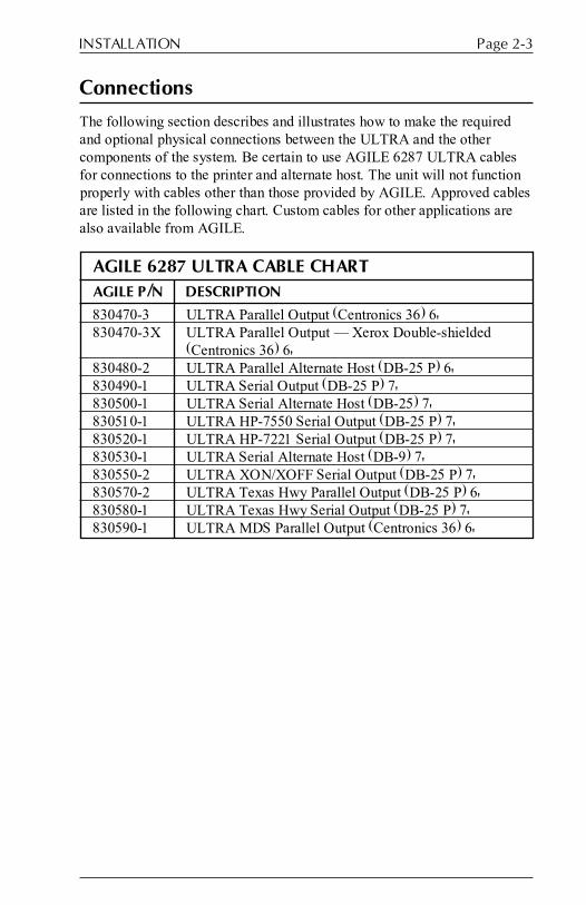
The following section describes and illustrates how to make the requiredand optional physical connections between the ULTRA and the othercomponents of the system. Be certain to use AGILE 6287 ULTRA cablesfor connections to the printer and alternate host. The unit will not functionproperly with cables other than those provided by AGILE. Approved cablesare listed in the following chart. Custom cables for other applications arealso available from AGILE.
AGILE 6287 ULTRA CABLE CHARTAGILE P/N DESCRIPTION
830470-3 ULTRA Parallel Output (Centronics 36) 6'830470-3X ULTRA Parallel Output � Xerox Double-shielded
(Centronics 36) 6'830480-2 ULTRA Parallel Alternate Host (DB-25 P) 6'830490-1 ULTRA Serial Output (DB-25 P) 7'830500-1 ULTRA Serial Alternate Host (DB-25) 7'830510-1 ULTRA HP-7550 Serial Output (DB-25 P) 7'830520-1 ULTRA HP-7221 Serial Output (DB-25 P) 7'830530-1 ULTRA Serial Alternate Host (DB-9) 7'830550-2 ULTRA XON/XOFF Serial Output (DB-25 P) 7'830570-2 ULTRA Texas Hwy Parallel Output (DB-25 P) 6'830580-1 ULTRA Texas Hwy Serial Output (DB-25 P) 7'830590-1 ULTRA MDS Parallel Output (Centronics 36) 6'

6287 ULTRA User�s ManualPage 2-4
6287 ULTRA Rear Panel
The rear panel of the ULTRA provides an on/off switch, a power cordoutlet, a coax port for connection to the CPU controller (RG62 A/U), aprinter port (parallel or serial), an alternate host port (parallel or serial) andtwo banks of dip switches.
OUTPUT SERIAL AND PARALLEL
ALTERNATE HOST INPUT SERIAL AND PARALLEL
117 VAC .5A
50/60 Hz 35W
FUSE 250V-1.0A SLO BLO
CONTROLLER COAX
RG 62 A/U
MODEL 6287 ULTRA
S/N 00000
This equipment complies with the requirements in Part 15 of FCC Rules for a Class A computing device. Operation of this equipment in a residential area may cause unacceptable interference to radio and TV reception requiring the operator to take whatever steps are necessary to correct the interference.
LR 69521 E.D.P. EQUIPMENT 47T8
Y
CAUTION-FOR CONTINUED PROTECTION AGAINST FIRE, REPLACE ONLY WITH SAME TYPE AND RATING OF FUSE
LISTED
UL®
®
1 2 3 4 5 6 7 8ON 1 2 3 4 5 6 7 8ON
OFF ON
A B
Alternate Host Port
Printer Port
Dip Switch Banks
CPU Port
On/Off Switch
Power Cord Outlet

Page 2-5INSTALLATION
6287 ULTRA Connection to Mainframe
Attach the device end of an RG62 A/U coax cable to the coax connector onthe rear panel of the ULTRA. Rotate the cable connector 1/4 turn clockwiseto lock it in place. Attach the other end of the coaxial cable to themainframe display printer adapter (DPA) or the cluster controller at thecoax port designated for the ULTRA. (The unit may also be attached withtwisted pair and balun.)
OUTPUT SERIAL AND PARALLEL
ALTERNATE HOST INPUT SERIAL AND PARALLEL
117 VAC .5A
50/60 Hz 35W
FUSE 250V-1.0A SLO BLO
CONTROLLER COAX
RG 62 A/U
MODEL 6287 ULTRA
S/N 00000
This equipment complies with the requirements in Part 15 of FCC Rules for a Class A computing device. Operation of this equipment in a residential area may cause unacceptable interference to radio and TV reception requiring the operator to take whatever steps are necessary to correct the interference.
LR 69521 E.D.P. EQUIPMENT 47T8
Y
CAUTION-FOR CONTINUED PROTECTION AGAINST FIRE, REPLACE ONLY WITH SAME TYPE AND RATING OF FUSE
LISTED
UL®
®
1 2 3 4 5 6 7 8ON 1 2 3 4 5 6 7 8ON
OFF ON
A B

6287 ULTRA User�s ManualPage 2-6
6287 ULTRA Connection to Printer/Plotter
Insert the DEVICE end of the AGILE printer cable into the connector onthe rear of the printer. Then connect the IC+/ULTRA end of the AGILEprinter cable to the output port of the ULTRA. Secure the cable to theprinter using the clips (parallel) or screws (serial) provided. The FCCrequires all printer interface cables to be properly shielded.
OUTPUT SERIAL AND PARALLEL
ALTERNATE HOST INPUT SERIAL AND PARALLEL
117 VAC .5A
50/60 Hz 35W
FUSE 250V-1.0A SLO BLO
CONTROLLER COAX
RG 62 A/U
MODEL 6287 ULTRA
S/N 00000
This equipment complies with the requirements in Part 15 of FCC Rules for a Class A computing device. Operation of this equipment in a residential area may cause unacceptable interference to radio and TV reception requiring the operator to take whatever steps are necessary to correct the interference.
LR 69521 E.D.P. EQUIPMENT 47T8
Y
CAUTION-FOR CONTINUED PROTECTION AGAINST FIRE, REPLACE ONLY WITH SAME TYPE AND RATING OF FUSE
LISTED
UL®
®
1 2 3 4 5 6 7 8ON 1 2 3 4 5 6 7 8ON
OFF ON
A B

Page 2-7INSTALLATION
6287 ULTRA Connection to Optional Alternate Host(s)
Connect the DEVICE end of the AGILE alternate host cable to theappropriate port on the alternate host. Secure the cable to the alternate hostusing the screws provided. Then connect the IC+/ULTRA end of the cableto the input port of the ULTRA. The FCC requires all alternate hostinterface cables to be properly shielded.
OUTPUT SERIAL AND PARALLEL
ALTERNATE HOST INPUT SERIAL AND PARALLEL
117 VAC .5A
50/60 Hz 35W
FUSE 250V-1.0A SLO BLO
CONTROLLER COAX
RG 62 A/U
MODEL 6287 ULTRA
S/N 00000
This equipment complies with the requirements in Part 15 of FCC Rules for a Class A computing device. Operation of this equipment in a residential area may cause unacceptable interference to radio and TV reception requiring the operator to take whatever steps are necessary to correct the interference.
LR 69521 E.D.P. EQUIPMENT 47T8
Y
CAUTION-FOR CONTINUED PROTECTION AGAINST FIRE, REPLACE ONLY WITH SAME TYPE AND RATING OF FUSE
LISTED
UL®
®
1 2 3 4 5 6 7 8ON 1 2 3 4 5 6 7 8ON
OFF ON
A B

6287 ULTRA User�s ManualPage 2-8
6287 ULTRA Connection to AC Outlet
Ensure that the power switch on the ULTRA is set in the OFF (up) position.Insert the device end of the power cord into the rear of the ULTRA. Insertthe male end of the power cord into a properly grounded wall receptacle.
OUTPUT SERIAL AND PARALLEL
ALTERNATE HOST INPUT SERIAL AND PARALLEL
117 VAC .5A
50/60 Hz 35W
FUSE 250V-1.0A SLO BLO
CONTROLLER COAX
RG 62 A/U
MODEL 6287 ULTRA
S/N 00000
This equipment complies with the requirements in Part 15 of FCC Rules for a Class A computing device. Operation of this equipment in a residential area may cause unacceptable interference to radio and TV reception requiring the operator to take whatever steps are necessary to correct the interference.
LR 69521 E.D.P. EQUIPMENT 47T8
Y
CAUTION-FOR CONTINUED PROTECTION AGAINST FIRE, REPLACE ONLY WITH SAME TYPE AND RATING OF FUSE
LISTED
UL®
®
1 2 3 4 5 6 7 8ON 1 2 3 4 5 6 7 8ON
OFF ON
A B

Page 2-9INSTALLATION
Sample Installation Diagrams
The following pages illustrate basic and optional setups of the 6287ULTRA.
6287 ULTRA Basic Setup
OUTPUT SERIAL AND PARALLEL
ALTERNATE HOST INPUT SERIAL AND PARALLEL
117 VAC .5A
50/60 Hz 35W
FUSE 250V-1.0A SLO BLO
CONTROLLER COAX
RG 62 A/U
MODEL 6287 ULTRA
S/N 00000
This equipment complies with the requirements in Part 15 of FCC Rules for a Class A computing device. Operation of this equipment in a residential area may cause unacceptable interference to radio and TV reception requiring the operator to take whatever steps are necessary to correct the interference.
LR 69521 E.D.P. EQUIPMENT 47T8
Y
CAUTION-FOR CONTINUED PROTECTION AGAINST FIRE, REPLACE ONLY WITH SAME TYPE AND RATING OF FUSE
LISTED
UL®
®
1 2 3 4 5 6 7 8ON 1 2 3 4 5 6 7 8ON
OFF ON
A B
AGILE Parallel
Printer Cable
RG 62 A/U Cable
Local Printer
Mainframe CPU or
Controller
Power Cord
3-Pronged AC Outlet
6287 ULTRA User�s ManualPage 2-10
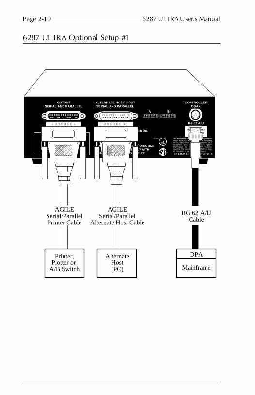
6287 ULTRA Optional Setup #1
OUTPUT SERIAL AND PARALLEL
ALTERNATE HOST INPUT SERIAL AND PARALLEL
117 VAC .5A
50/60 Hz 35W
FUSE 250V-1.0A SLO BLO
CONTROLLER COAX
RG 62 A/U
MODEL 6287 ULTRA
S/N 00000
This equipment complies with the requirements in Part 15 of FCC Rules for a Class A computing device. Operation of this equipment in a residential area may cause unacceptable interference to radio and TV reception requiring the operator to take whatever steps are necessary to correct the interference.
LR 69521 E.D.P. EQUIPMENT 47T8
Y
CAUTION-FOR CONTINUED PROTECTION AGAINST FIRE, REPLACE ONLY WITH SAME TYPE AND RATING OF FUSE
LISTED
UL®
®
1 2 3 4 5 6 7 8ON 1 2 3 4 5 6 7 8ON
OFF ON
A B
AGILE Serial/Parallel Printer Cable
AGILE Serial/Parallel
Alternate Host Cable
RG 62 A/U Cable
Printer, Plotter or
A/B Switch
Alternate Host (PC) Mainframe
DPA

Page 2-11INSTALLATION
6287 ULTRA Optional Setup #2
OUTPUT SERIAL AND PARALLEL
ALTERNATE HOST INPUT SERIAL AND PARALLEL
117 VAC .5A
50/60 Hz 35W
FUSE 250V-1.0A SLO BLO
CONTROLLER COAX
RG 62 A/U
MODEL 6287 ULTRA
S/N 00000
This equipment complies with the requirements in Part 15 of FCC Rules for a Class A computing device. Operation of this equipment in a residential area may cause unacceptable interference to radio and TV reception requiring the operator to take whatever steps are necessary to correct the interference.
LR 69521 E.D.P. EQUIPMENT 47T8
Y
CAUTION-FOR CONTINUED PROTECTION AGAINST FIRE, REPLACE ONLY WITH SAME TYPE AND RATING OF FUSE
LISTED
UL®
®
1 2 3 4 5 6 7 8ON 1 2 3 4 5 6 7 8ON
OFF ON
A B
AGILE Serial/Parallel Printer Cable
AGILE Serial/Parallel
Alternate Host Cable
Coax Cable (5000' Maximum)
Printer, Plotter or
A/B Switch
Alternate Host (PC)
Cluster Controller
(Local)
Coax Cable
TerminalMainframe
DPA Channel
SNA or non-SNA

6287 ULTRA User�s ManualPage 2-12
6287 ULTRA Optional Setup #3
OUTPUT SERIAL AND PARALLEL
ALTERNATE HOST INPUT SERIAL AND PARALLEL
117 VAC .5A
50/60 Hz 35W
FUSE 250V-1.0A SLO BLO
CONTROLLER COAX
RG 62 A/U
MODEL 6287 ULTRA
S/N 00000
This equipment complies with the requirements in Part 15 of FCC Rules for a Class A computing device. Operation of this equipment in a residential area may cause unacceptable interference to radio and TV reception requiring the operator to take whatever steps are necessary to correct the interference.
LR 69521 E.D.P. EQUIPMENT 47T8
Y
CAUTION-FOR CONTINUED PROTECTION AGAINST FIRE, REPLACE ONLY WITH SAME TYPE AND RATING OF FUSE
LISTED
UL®
®
1 2 3 4 5 6 7 8ON 1 2 3 4 5 6 7 8ON
OFF ON
A B
AGILE Serial/Parallel Printer Cable
AGILE Serial/Parallel
Alternate Host Cable
Coax Cable (5000' Maximum)
Printer, Plotter or
A/B Switch
Alternate Host (PC)
Cluster Controller (Remote)
Coax Cable
TerminalMainframe
DPA
Serial
Channel
Modem ModemPhone LineSNA/SCS-EBCDIC
BI/SYNC-DSC
3705/3725 Communication
Processor

Page 2-13INSTALLATION
6287 ULTRA Power Up
Power on the printer. After the printer completes its power on initializationsequence, verify that it is on line and ready to receive and print data. Ifnecessary, refer to the printer user�s manual for detailed information.
Power on the alternate host, if using an alternate host.
Power on the ULTRA by pushing down the on/off switch. The followingStatus Indicator Lights should all be on: POWER, CU SIGNAL andPRINTER READY. All other lights should be off.
The ULTRA is shipped with its dip switches and configuration options setfor the most common environments. If the factory default settings areappropriate for the user�s environment, the ULTRA is ready to be used forprinting.
If the user�s environment differs from the one for which the ULTRA isconfigured, the user may need to refer to the following chapters on dipswitch settings, configuration options and the other user-changeablefeatures of the ULTRA.


DIP SWITCH SETTINGS
General Information
The dip switches on the rear panel of the ULTRA are used to prepare theunit for different types of printers and alternate hosts. They are also used tosend diagnostic reports to the printer. Some dip switch settings determinethe way in which the ULTRA can be configured.
The default settings � all switches in the OFF (up) position � ready theunit for a parallel printer and an optional parallel alternate host (althoughOption #50 must still be configured for an alternate host; see Section 5 �Configuration Options). If the user has a serial alternate host or a serialprinter, the dip switch settings must be changed.
Note: If the ULTRA is powered on, the RESET button on the frontpanel must be pressed after any dip switch setting is changed before thechange will take effect.
Common Printer Interface Settings
Parallel Interfacing(Default � all OFF/up):
Serial Interfacing,N/8/1, 1200 baud:
Serial Interfacing,N/8/1, 9600 baud:
SECTION 3
ON 1 2 3 4 5 6 7 8
Switch Bank A
ON 1 2 3 4 5 6 7 8
Switch Bank A
ON 1 2 3 4 5 6 7 8
Switch Bank A

6287 ULTRA User�s ManualPage 3-2
Switch Bank A Settings
General Information
In addition to sending a a printer test or auto buffer report to the printer,Switch Bank A is used to control interfacing only with the port labeled�OUTPUT SERIAL AND PARALLEL.�
A1 � Printer Interfacing
Parallel: Serial:
ON 1 2 3 4 5 6 7 8
Switch Bank A
ON 1 2 3 4 5 6 7 8
Switch Bank A
When this dip switch is OFF (up) and either the RESET button is pressed orthe unit is powered up, the ULTRA is configured for interfacing with aparallel printer. For serial printer interfacing, the dip switch should be in theON (down) position.
A2 � Printer Test
Normal Operation: Printer Test:
ON 1 2 3 4 5 6 7 8
Switch Bank A
ON 1 2 3 4 5 6 7 8
Switch Bank A
When this dip switch is ON (down) and either the RESET button is pressedor the unit is powered up, the ULTRA is prepared for a Printer Test. Afterchanging to this setting, press the TEST button, and the unit will output acontinuous stream of the ASCII or EBCDIC character sets from SPACEthrough DELETE, followed by a CR/LF. This feature is used duringinstallation and troubleshooting to verify proper communication betweenthe ULTRA and the printer.
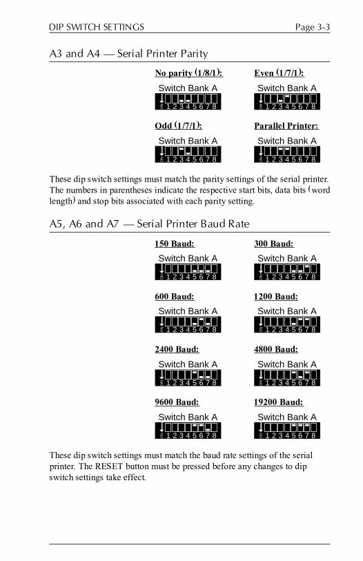
Page 3-3DIP SWITCH SETTINGS
A3 and A4 � Serial Printer Parity
No parity (1/8/1): Even (1/7/1):
ON 1 2 3 4 5 6 7 8
Switch Bank A
ON 1 2 3 4 5 6 7 8
Switch Bank A
Odd (1/7/1): Parallel Printer:
ON 1 2 3 4 5 6 7 8
Switch Bank A
ON 1 2 3 4 5 6 7 8
Switch Bank A
These dip switch settings must match the parity settings of the serial printer.The numbers in parentheses indicate the respective start bits, data bits (wordlength) and stop bits associated with each parity setting.
A5, A6 and A7 � Serial Printer Baud Rate
150 Baud: 300 Baud:
ON 1 2 3 4 5 6 7 8
Switch Bank AO
N 1 2 3 4 5 6 7 8
Switch Bank A
600 Baud: 1200 Baud:
ON 1 2 3 4 5 6 7 8
Switch Bank A
ON 1 2 3 4 5 6 7 8
Switch Bank A
2400 Baud: 4800 Baud:
ON 1 2 3 4 5 6 7 8
Switch Bank A
ON 1 2 3 4 5 6 7 8
Switch Bank A
9600 Baud: 19200 Baud:
ON 1 2 3 4 5 6 7 8
Switch Bank A
ON 1 2 3 4 5 6 7 8
Switch Bank A
These dip switch settings must match the baud rate settings of the serialprinter. The RESET button must be pressed before any changes to dipswitch settings take effect.

6287 ULTRA User�s ManualPage 3-4
A8 � Auto Buffer Report
Normal Operation: Buffer Dump:
When this dip switch is ON (down) and either the RESET button is pressedor the unit is powered up, the ULTRA will output a hexadecimal listing ofthe ULTRA buffer contents before each host print operation. This feature isused only to debug host application problems.
Switch Bank B Settings
General Information
In addition to being used for configuration and to send various reports tothe printer, Switch Bank B is used to control interfacing only with the portlabeled �ALTERNATE HOST INPUT SERIAL AND PARALLEL.� Thisis an input-only port to which an alternate host may be attached (serial orparallel). If a serial alternate host is connected to this port, dip switches B1,B2, B3, B4 and B5 must be set to match the parity and baud rate of thealternate host.
B1 and B2 � Serial Alternate Host Parity
No parity (1/8/1): Even (1/7/1):
Odd (1/7/1):
These dip switch settings must match the parity of the serial alternate hostconnected to the port labeled �ALTERNATE HOST INPUT SERIAL ANDPARALLEL.� The numbers in parentheses indicate the respective start bits,data bits (word length) and stop bits associated with each parity setting.
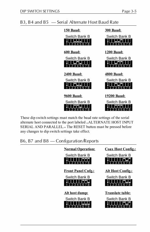
Page 3-5DIP SWITCH SETTINGS
B3, B4 and B5 � Serial Alternate Host Baud Rate
150 Baud: 300 Baud:
ON 1 2 3 4 5 6 7 8
Switch Bank B
ON 1 2 3 4 5 6 7 8
Switch Bank B
600 Baud: 1200 Baud:
ON 1 2 3 4 5 6 7 8
Switch Bank B
ON 1 2 3 4 5 6 7 8
Switch Bank B
2400 Baud: 4800 Baud:
ON 1 2 3 4 5 6 7 8
Switch Bank B
ON 1 2 3 4 5 6 7 8
Switch Bank B
9600 Baud: 19200 Baud:
ON 1 2 3 4 5 6 7 8
Switch Bank BO
N 1 2 3 4 5 6 7 8
Switch Bank B
These dip switch settings must match the baud rate settings of the serialalternate host connected to the port labeled �ALTERNATE HOST INPUTSERIAL AND PARALLEL.� The RESET button must be pressed beforeany changes to dip switch settings take effect.
B6, B7 and B8 � Configuration/Reports
Normal Operation: Coax Host Config.:
ON 1 2 3 4 5 6 7 8
Switch Bank B
ON 1 2 3 4 5 6 7 8
Switch Bank B
Front Panel Cnfg.: Alt Host Config.:
ON 1 2 3 4 5 6 7 8
Switch Bank B
ON 1 2 3 4 5 6 7 8
Switch Bank B
Alt host dump: Translate table:
ON 1 2 3 4 5 6 7 8
Switch Bank B
ON 1 2 3 4 5 6 7 8
Switch Bank B

6287 ULTRA User�s ManualPage 3-6
Setting these switches and pressing the RESET button or powering up theULTRA will determine whether the ULTRA will operate normally, orwhether it can be configured by sending a command sequence from thecoax host, from the ULTRA front panel or from an alternate host.
With all three switches in the ON (down) position, a dump of the alternatehost data stream can be sent to the printer after pressing the RESET buttonon the ULTRA front panel.
A translate table report can be sent to the printer by pressing the RESETand CANCEL buttons when dip switch B7 is in the ON (down) position.
Switch Bank Tables
Switch Bank A � Printer Interfacing/Tests
Function Printer Printer Printer Printer BufferPort Test Parity Baud Rate Dump
A1 A2 A3 A4 A5 A6 A7 A8
Par Out Up
Serial Out Down
Normal Up
Test Print Down
No parity Down Down
Odd Up Down
Even Down Up
150 baud Down Down Down
300 Down Down Up
600 Down Up Down
1200 Down Up Up
2400 Up Down Down
4800 Up Down Up
9600 Up Up Down
19.2K Up Up Up
Normal Up
Hex dump Down

Page 3-7DIP SWITCH SETTINGS
Switch Bank B � Serial Alt Host Interfacing/Config/Reports
Function Alt Host Alt Host Configuration/ReportsParity Baud Rate
B1 B2 B3 B4 B5 B6 B7 B8
No parity Down Down
Odd Up Down
Even Down Up
150 baud Down Down Down
300 Down Down Up
600 Down Up Down
1200 Down Up Up
2400 Up Down Down
4800 Up Down Up
9600 Up Up Down
19.2K Up Up Up
Normal Up Up Up
Coax Host Up Down Up
Front Pnl. Up Up Down
Alt Host Up Down Down
Alt Dump Down Down Down
Trans Tbl. Up Down Up


TROUBLESHOOTING
General Information
This section describes how to print various reports. These reports are usedto test the connections between the ULTRA and the other components ofthe user�s system, and to troubleshoot problems encountered in sendingproperly formatted documents to the printer. This section also describeshow to contact AGILE technical support and how to upgrade the ULTRAfirmware EPROM.
Connection Tests
The following tests will verify that proper connections have been madebetween the ULTRA, the coax host, the printer and the alternate host.
Printer Test
One of the features of the ULTRA is a printer test that can be used to verifythe connection between the printer and the ULTRA. To perform this test,put dip switch A2 in the ON (down) position, and press the RESET buttonon the ULTRA front panel (or power up the unit). Then press the TESTbutton. The printer will begin printing a continuous stream of the EBCDICor ASCII character sets from SPACE through DELETE, followed by a CR/LF.
Allow the printer to output several pages of data, then verify that all of thepages are formatted identically. To end the printer test, put dip switch A2 inthe OFF (up) position, and press the RESET button. A sample printer testcan be found in the Appendix.
If the report does not print:
� Check that both the ULTRA and the printer are connected to a powersource, powered on and on line.
� Verify that the printer is securely connected to the ULTRA outputport with an ULTRA cable (refer to the cable chart in Section 2 �Installation). The cable end labeled DEVICE should be attached tothe printer, and the end labeled IC+/ULTRA should be attached tothe ULTRA. The ULTRA will not function properly with cablesother than those provided by AGILE.
SECTION 4

6287 ULTRA User�s ManualPage 4-2
� The ULTRA may be configured incorrectly for a serial or parallelprinter (the default is parallel). Select serial output by setting dipswitch A1 in the ON (down) position, then press the RESET button.Select parallel output by setting all Bank A dip switches in the OFF(up) position, then press the RESET button.
� If using a serial printer, make sure that the settings of ULTRA dipswitches A3 and A4 match the printer interface settings for parityand that dip switches A5, A6 and A7 match the printer interfacesettings for baud rate. The RESET button must be pressed for thechanges to take effect.
� If the printer is connected via parallel interfacing, the CHECK StatusIndicator Light on the ULTRA front panel will be on if there is ahardware error on the parallel port. This usually indicates a problemwith the printer, such as a paper jam.
� Confirm that the printer is functioning properly by having it performa self test. Refer to the printer user�s manual for instructions.
If the report prints garbage:
� The ULTRA may be incorrectly configured for ASCII or EBCDIC(the default is ASCII). This setting is determined by configurationOption #10. Refer to Section 5 � Configuration Options for infor-mation on changing the settings of configuration options.
General Configuration Report
This report will print out a list of all of the ULTRA configuration options,including programmable function strings, along with their current settingsand the current firmware version number. This report is useful for findingthe causes of various printing and formatting problems. This test shouldalso be printed before and after changing any configuration options.
To print the report, press the TEST button on the front panel of the ULTRAwhen the unit is in normal operating mode. A sample report with all defaultvalues selected is included in the Appendix.
Coax Host Verification
After successfully completing a General Configuration Report, verify thehost connection to the ULTRA by sending a Local Copy or a typical host-generated print transaction to the printer (one or two pages). Refer to thesystem documentation for instructions. Verify that the transaction isproperly formatted and output by the printer.

Page 4-3TROUBLESHOOTING
If it does not print:
� Check that the ULTRA and the coax host are securely connectedwith an RG62 A/U coax cable, and that the CU light on the ULTRAfront panel is on, indicating a proper connection. If the LED isflashing on and off, or if it is dim, proper communication is notestablished between the coax host and the ULTRA.
� Make certain that the ULTRA is defined to the system as a 3287printer with a 4K physical buffer size.
� Confirm that the ULTRA is defined to the system as an LU1 if usingSCS data streams, or as an LU3 if using DSC data streams.
� If using VTAM or another Network Control Program, make certainthat the ULTRA is defined as a type 2 physical unit.
If the print output is not formatted correctly:
� Refer to the printer user�s manual for the commands necessary toformat the printer�s output to suit the needs of the application.
� Print the document again using the ULTRA Auto Buffer Report.
Auto Buffer Report
An Auto Buffer Report is a tool useful for diagnostics, and it willsometimes be requested by AGILE technical support for diagnosingprinting problems. An Auto Buffer Report will automatically output abuffer dump of the data that the ULTRA receives along with a printout ofthe host print job being sent to the printer.
To print using the buffer dump feature, set dip switch A8 in the ON (down)position, and press the RESET button on the ULTRA front panel. Thensend the local copy or typical mainframe print job to the printer.
After the Auto Buffer Report has printed, set dip switch A8 in the OFF (up)position, and press the RESET button on the ULTRA front panel. A sampleAuto Buffer Report can be found in the Appendix.
Translate Table Report
Some formatting problems may be caused by inappropriate changes to thetranslate tables, especially changes made to values that perform specialfunctions. A translate table report allows the user to compare the currentvalues in the table being used to translate the document to the values in theoriginal table. This report should be printed before and after making anychanges to the translate tables. For information on determining the activetranslate table, refer to Section 7 � Translate Tables.
6287 ULTRA User�s ManualPage 4-4
To print a Translate Table Report, set dip switch B7 in the ON (down)position, press the RESET button on the ULTRA front panel, then press theCANCEL button. The printer will print each of the translate tables withtheir current values.
After the report has finished printing, set dip switch B7 to its formerposition, and press the RESET button on the ULTRA front panel. A sampleTranslate Table Report with all default values selected can be found in theAppendix.
Alternate Host Verification
Test the alternate host by sending a Print Screen job (or device equivalent)from the alternate host to the printer attached to the ULTRA. Refer to thealternate host system documentation for instructions on sending a PrintScreen command.
Before beginning this test, make certain that Option #50 has been set toenable the alternate host port. Refer to Section 5 � Configuration Optionsfor information on changing this option.
Note: Make certain that no coax host print job is being processed at thesame time as the alternate host print job.
If it does not print:
� Check that the alternate host is powered on and securely connectedto the ULTRA with an AGILE-approved cable. The cable endlabeled DEVICE should be attached to the alternate host, and the endlabeled IC+/ULTRA should be attached to the ULTRA. The unit willnot function properly with cables other than those provided byAGILE.
� If using a serial cable, make sure that the settings of dip switches B1and B2 (and/or A3 and A4) match the serial interface settings forparity, and that the settings of dip switches B3, B4 and B5 (and/orA5, A6 and A7) match the serial interface settings for baud rate. TheRESET button must be pressed for the changes to take effect.
� Note the state of the ALT HOST light on the ULTRA front panel.
Alternate Host Buffer Dump
Users with problems in printing properly formatted documents from thealternate host may print a buffer dump of the data being sent from thealternate host to the printer. AGILE technical support will sometimesrequest this report when diagnosing printing problems.

Page 4-5TROUBLESHOOTING
To print an Alternate Host Buffer Dump, set dip switches B6, B7 and B8 inthe ON (down) position, then press the RESET button on the ULTRA frontpanel. Print the offending document from the alternate host, and the printerwill output a document similar to the Auto Buffer Report.
After the document has finished printing, set dip switches B6, B7 and B8 totheir former locations, and press the RESET button on the ULTRA frontpanel. A sample Alternate Host Buffer Dump can be found in theAppendix.
Contacting AGILE Technical Support
Before contacting AGILE technical support, print out each of the reportsdescribed earlier in this chapter, and check them for potential sources ofproblems. If the problem persists after making the obvious corrections,please have the following information available before calling AGILE:
6287 ULTRA serial number (found on the back panel): S/N
Firmware version number (found in the printed reports, on the EPROMchip and on the bottom panel of the 6287 ULTRA):
Cluster controller model #:
SCS or DSC mode:
Coax host cable type and length:
Printer or plotter make: Model #:
Printer or plotter cable #:
Plotter graphics software name:
Parallel or serial interface:
If serial: Parity:
Baud:
Handshake:
Alternate host make: Model #:
Alternate host cable #:
Parallel or serial interface:
If serial: Parity:
Baud:
Handshake:

6287 ULTRA User�s ManualPage 4-6
What front panel Status Indicator Lights are ON when the problem occurs?:
CU ALT PRINTER HOLD DATA KEYPOWER SIGNAL HOST READY PRINT OUT SCS CHECK TEST DOWN
Dip switch settings (specify ON/down and OFF/up positions):
Switch Bank A: 1___ 2___ 3___ 4___ 5___ 6___ 7___ 8___
Switch Bank B: 1___ 2___ 3___ 4___ 5___ 6___ 7___ 8___
AGILE toll-free technical support is available between the hours of7:00 a.m. and 4:30 p.m. PST. For Express Exchange Service customers whowould like next-business-day replacement of a unit, AGILE technicalsupport must be contacted early enough so that the need for a replacementunit can be determined before 2:00 p.m. PST. Refer to page xii for warrantyinformation.
Call (800) 538-1634, or FAX (510) 724-2222.
Firmware Replacement Instructions
Occasionally the firmware in the 6287 ULTRA may require replacementfor updating or enhancing. To change the firmware, follow these steps:
1. Make certain that the unit is powered off and disconnected from anypower source.
2. Remove all cables, including the power cable, from the back panel of theULTRA.
3. Remove the four screws from the bottom of the ULTRA.
4. Holding the front and back of the unit, slide the cover off.
5. Find the firmware EPROM on the main logic board at location U11; thelabel on the chip will indicate the version number (e.g., 6287 V.46.00).Remove the chip with a chip puller or a flat-bladed, non-magnetizedscrewdriver, noting the position of the alignment notch.
6. Place the new firmware in the socket, aligning the notched edge in thesame direction as the original EPROM.
7. Reassemble the unit, and replace the cables.

Page 4-7TROUBLESHOOTING
The AGILE Bulletin Board System
To upload files that do not print correctly, or to download information, callthe AGILE BBS:
1. Load the communications software.
2. Set up the modem:
� Baud rate: Fastest setting available (AGILE supports speeds of upto 28.8 with both V.FC and V.34 modems)
� Data bits: 8� Stop bits: 1� Parity: None
3. Dial 15107248073. If using a line with Call Waiting, dial*70,15107248073 to disable Call Waiting.
4. As prompted by the bulletin board, enter the following:
� First name� Last name� �Y� to confirm name� Password� Re-enter password� �C� to continue� Company name� Voice phone number
5. Now answer a few questions about your system:
� Hot keys (Y/N) allow options to be selected without pressing Enter� Color menus � �A� = auto-detect� Default editor mode � �F� = full screen (if the user has ANSI
terminal emulation); �L� = line edit (if the user does not haveANSI terminal emulation)
� Protocol for file transfers � the preferred file transfer protocol isZMODEM (�Z�), but the user may also use any of the otherprotocols displayed on the screen.
6. The bulletin board will then ask if you want to display the Bulletin menu(Y/N), inform you that you have no personal mail, and after you pressEnter, will display the Main menu.

6287 ULTRA User�s ManualPage 4-8
7. To download a file, perform the following steps:
� Press �F� to display the File menu� Press �L� to List files� Press �1� to go to File area 1 (AGILE software download area)� Press �M� to Mark the file� Type the number of the file to be downloaded� Press �D� to Download the file� Press �D� to confirm the download� Perform the local download procedure according to your
communications software instructions
8. After downloading the file, press Enter, then exit the bulletin board withthe following steps:
� Press �S� to Stop downloading and exit the Download menu� Press �Q� to Quit to the Main menu� Press �G� to Goodbye and Logoff� Press �Y� to confirm the Logoff
CONFIGURATION OPTIONS
General Information
This section describes each of the parameters of the General ConfigurationOptions that the user can select to adapt the ULTRA to the user�s specificenvironment.
Configuring the ULTRA changes the way in which it handles the datastream from the coax host or alternate host before the data is sent to theprinter or plotter. The configuration option parameters allow the user tochange printer output, page formatting, host parameters, transparencymodes, etc. Under many circumstances, the ULTRA configuration will nothave to be modified, because it is already set up for the most commonenvironments.
Before changing any of the configuration settings, the user should print aGeneral Configuration Report that will display the current settings. AGeneral Configuration Report can be generated by pressing the TESTbutton on the front panel of the ULTRA when the unit is in normaloperating mode. A sample report can be found in the Appendix.
The most critical part of configuring the ULTRA is correctly choosing theoutput settings. If the user�s printer or alternate host operates in serial mode,refer to Section 3 � Dip Switch Settings before continuing.
Besides the limited number of functions determined by the dip switchsettings, there are three ways to configure the options of the ULTRA. Theycan be configured from the ULTRA front panel with some limitations, orthey can be configured from the coax host or from an alternate host. Eachof the three methods of configuring the ULTRA is described in asubsequent section.
The easiest method of changing the ULTRA options is from the front panel,but some variables cannot be selected. Programmable function strings(PFSs) and translate tables are editable only from the coax host or from analternate host.
SECTION 5

6287 ULTRA User�s ManualPage 5-2
Configuration Option Descriptions
1 � Column Width
This option allows the user to limit the number of printable columns perpage to any value between 0 and 255. The value of this option is the lastcolumn at which the ULTRA will allow any character to be printed beforesending a CR/LF sequence. The default value is 132. A value of 0 impliesan infinite line length.
Note: To avoid unexpected formatting results, this option should be set toinfinite line length if any of the following are true. Refer to Section 12 �DisplayWrite 370 Support for more information:
� the user or the user�s application embeds escape sequences in thedata stream
� the user or the user�s application embeds transparency or pseudotransparency strings in the data stream
� the user embeds ULTRA commands (configuration, translate table orPFS commands) within print jobs
This option should not be set to infinite line length if Option #15 � BoldPrint Emulation is set to any value other than C (none).
2 � Lines Per Page
This option allows the user to set the number of printable lines per page toany value between 0 and 255. The value of this option is the last line on thepage at which the ULTRA will allow any character to be printed beforesending a form feed. The default value is 0, which implies an infinite pagelength.
Note: To avoid unexpected formatting results, this option should be set toinfinite page length if any of the following are true. Refer to Section 12 �DisplayWrite 370 Support for more information:
� the user or the user�s application embeds escape sequences in thedata stream
� the user or the user�s application embeds transparency or pseudotransparency strings in the data stream
� the user embeds ULTRA commands (configuration, translate table orPFS commands) within print jobs

Page 5-3CONFIGURATION OPTIONS
3 � Line Spacing
This option allows the user to set line spacing to any value between 1 and 9.Any line feeds received from the coax host or sent out by the ULTRA aremultiplied by the value of this option. The default is 1 (single spacing).
4 � Local Copy Null Line Suppression
In a local copy or DSC print job, this option determines whether or not linescontaining only nulls are printed. The default value is �Yes.�
5 � Xerox 36 Hex Transparency
If this option is set to �Yes,� Xerox 36 Hex transparency is enabled. If thisoption is set to �No,� 36h will be ignored. The default value is �No.� Referto Section 11 � Transparency Modes for more information.
Note: If this option is set to �Yes,� Option #1 � Column width should beset to 0 (infinite line length), Option #2 � Lines Per Page should be set to 0(infinite page length), and Option #15 � Bold Print Emulation should beset to C (none). Otherwise, unpredictable formatting errors could occur.Refer to Section 12 � DisplayWrite 370 Support for more information.
6 � Form Feed Before Local Copy
Determines whether or not a form feed will be sent to the printer beforebeginning a local copy. The default value is �No.�
7 � Form Feed After Local Copy
Determines whether or not a form feed will be sent to the printer afterfinishing a local copy. The default value is �Yes.�
8 � New Line Order
Determines whether new lines will be sent to the printer as: (A) CR/LF (acarriage return followed by a line feed) or as (B) LF/CR. The default is (A).

6287 ULTRA User�s ManualPage 5-4
9 � PA Key Usage
If set to (A) Normal, and if the ULTRA is in SCS mode, the PA1 and PA2keys on the ULTRA will function as the PA keys on a 3287 printer. If set to(B), PA1 will send PFS 7 to the printer, and PA2 will send PFS 8 to theprinter. The default value is (A) Normal. Refer to Section 9 �Programmable Function Strings for more information on PFSs.
10 � Output in ASCII or EBCDIC
Some printer types (such as Xerox 4045s) can accept EBCDIC data. Thisoption determines whether the ULTRA outputs data in the (A) ASCII or(B) EBCDIC character set. A third option, (C), will have the ULTRA sendcoax host data to the printer in EBCDIC and alternate host data in ASCII.The default value is (A).
Note: Option C is useful only for users with an alternate host and a Xeroxprinter capable of changing on line from XES mode to HP PCL emulation.These printers include the models 4030, 4045-160, 4187, 4213 and 4235. Ifthe user selects option C, the printer must be configured by the user to startin XES mode using the EBCDIC character set. Additionally, PFS B � CoaxHost PFS must be programmed with the =MCK= command to change toXES mode, and PFS C � Alternate Host PFS must be programmed with the=MCK= command to change to the HP PCL emulation. Refer to the Xeroxprinter programmer reference for detailed information on changingemulations on line. Refer to Section 6 � Programmable Function Stringsfor information about PFSs.
11 � APL Output
In conjunction with Option #10 and Option #20, this option determineswhether or not APL output is allowed. If this option is set to �Yes,� APLoutput will be allowed. The default value is �No.�
Note: Option #10 must be set to (A), because only ASCII output issupported for APL. Additionally, Option #20 must set to (B) 2K with EABor (D) 4K with EAB. Additional information regarding APL support can befound in Section 7 � Translate Tables and Section 13 � Coax HostConsiderations.
12 � Reserved
This option is reserved.

Page 5-5CONFIGURATION OPTIONS
13 � Suppress Spaces Before Pseudo Transparent Packets
If this option is set to �Yes,� any spaces or null characters in between apseudo transparent packet and the preceding printable character will not beoutput to the printer. The default value is �No.� Refer to Section 11 �Transparency Modes for more information.
14 � Suppress Carriage Control Characters
If this option is set to �Yes,� all carriage control characters generated by thehost (CR, LF, NL, FF) will not be output to the printer, and the ULTRA willnot generate carriage control characters for MPP enforcement. Refer toSection 13 � SCS Data Streams for details. The default value is �No.�
15 � Bold Print Emulation
Determines how the ULTRA implements bold printing. The choices are:(A) 3287 printer emulation, (B) DisplayWrite 370 emulation or (C) None.The default value is (C). For more information, refer to section 12 �DisplayWrite 370 Support.
Note: To avoid unexpected formatting results, this option should be set to C(none) if any of the following are true. Refer to Section 12 � DisplayWrite370 Support for more information:
� the user or the user�s application embeds escape sequences in thedata stream
� the user or the user�s application embeds transparency or pseudotransparency strings in the data stream
� the user embeds ULTRA commands (configuration, translate table orPFS commands) within print jobs
� Option #1 � Column Width is set to 0 (infinite line length)
16 � Suppress Leading Spaces
Some applications insert leading white spaces in the data stream. If thisoption is set to �Yes,� all leading white space characters (nulls and spaces)at the beginning of each print request will be suppressed. The default valueis �No.�

6287 ULTRA User�s ManualPage 5-6
17 � Reserved
This option is reserved.
18 � Reserved
This option is reserved.
19 � Reserved
This option is reserved.
20 � Physical Buffer Size
Determines whether the ULTRA uses a physical buffer of (A) 2K, (B) 2Kwith EAB, (C) 4K or (D) 4K with EAB. This parameter must match thebuffer size that the host expects on the channel to which the ULTRA isattached. The default value is (C), and it is most efficient for many systems.
Note: For APL support, the user must select (B) or (D). Additionalinformation regarding APL support can be found in Section 7 � TranslateTables and Section 13 � Coax Host Considerations.
21 � Logical Buffer Size
Determines whether the ULTRA uses a logical buffer of (A) 960 bytes,(B) 1920 bytes, (C) 2560 bytes, (D) 3440 bytes or (E) 3564 bytes. Thisparameter must match the contents of the log mode entry table (found onthe host system). The default value is (D).
22 � Reserved
This option is reserved.
23 � Reserved
This option is reserved.
24 � Reserved
This option is reserved.
Page 5-7CONFIGURATION OPTIONS
25 � Centronics or Dataproducts Parallel
This option determines whether the ULTRA implements a (A) Centronicsor (B) Dataproducts parallel interface. The default value is (A). Users witholder Dataproducts printers using their proprietary DB interface must alsoprovide AGILE with the pin-out chart, so a custom cable can be made.
26 � Intervention Required
The host should be informed when a problem is detected at the printer orthe protocol converter. This option determines whether or not the ULTRAtransmits an Intervention Required message to the coax host when a printerfault (e.g., out of paper) is reported by a parallel-attached printer. Thedefault value is �Yes.�
In the event of a parallel printer error, the PRINTER READY light on theULTRA front panel will go out, and the CHECK light will go on.
Coax host systems react differently to Intervention Required. In some cases,the printer may be disabled until a command is sent to reacquire the printer.After the error condition is cleared, the ULTRA informs the system, andprinting can restart either at page 1, from the top of the page where theintervention occurred, or from where the printing stopped.
If the handling of intervention is causing a problem, the best solution is tochange the way in which the system responds to it. For example, since laserprinters buffer all data received, it is not necessary to retransmit any datafrom a previous page. The system should be configured to halt when anIntervention Required is received, so when the error condition is cleared,the system will continue transmitting from where it left off.
Intervention Required can be disabled to prevent the error message frombeing sent, or a delay can be set to give the user time to fix the problem.
27 � Intervention Required Delay
This option determines how many minutes the ULTRA will wait afterreceiving a parallel printer fault indication before sending an InterventionRequired message to the coax host (if Option #26 is set to �Yes�). If theproblem is minor, such as a paper jam, the user may correct the problembefore it needs to be reported. The user may select any value between 0(immediate) and 255. The default value is 10 minutes.
28 � Reserved
This option is reserved.

6287 ULTRA User�s ManualPage 5-8
29 � Reserved
This option is reserved.
30 � Pseudo Transparency Mode (PTM) Selection
Determines which of two methods will be used to begin pseudotransparency mode: (A) Trigger 1 + Trigger 2 or (B) Trigger 1 + CountByte. The default value is (A). Refer to Section 11 � Transparency Modesfor more information.
31 � Discard PTM Terminating Delimiter
Determines whether or not the ULTRA, when Option #30 is set to(A) Trigger 1 + Trigger 2 PTM, will discard the character that terminatesPTM (i.e., the first hexadecimal character that is outside the range of 0-9 orA-F). The default value is �No.� Refer to Section 11 � TransparencyModes for more information.
32 � DSC Trigger 1
Determines which DSC character will be used (in conjunction with eitherTrigger 2 or a Count Byte, depending upon the setting of Option #30) tosignal the start of PTM. The user may enter any two-character hexadecimalvalue that will not otherwise be found in the data stream. The default valueis a DSC cent sign (¢) 1Bh. Refer to Section 11 � Transparency Modes formore information. This character is also used as a trigger for configuringthe ULTRA, invoking PFSs and programming PFSs from the coax host.
Note: The Trigger 1 character should be reserved for this use only. Anyother use of the Trigger 1 character may produce unpredictable results.
33 � DSC Trigger 2
Determines which DSC character must follow Trigger 1 in order to startPTM when Option #30 is set to (A). The user may enter any two-characterhexadecimal value, except for 18h (?), 2Eh (%), 19h (!) and 30h (&), whichare used by the ULTRA for other purposes. The default value is a DSCdollar sign ($) 1Ah. Refer to Section 11 � Transparency Modes for moreinformation.

Page 5-9CONFIGURATION OPTIONS
34 � SCS Trigger 1
Determines which SCS character will be used (in conjunction with eitherTrigger 2 or a Count Byte, depending upon the setting of Option #30) tosignal the start of PTM. The user may enter any two-character hexadecimalvalue that will not otherwise be found in the data stream. The default valueis an SCS cent sign (¢) 4Ah. Refer to Section 11 � Transparency Modesfor more information. This character is also used as a trigger forconfiguring the ULTRA, invoking PFSs and programming PFSs from thecoax host.
Note: The Trigger 1 character should be reserved for this use only. Anyother use of the Trigger 1 character may produce unpredictable results.
35 � SCS Trigger 2
Determines which SCS character must follow Trigger 1 in order to startPTM when Option #30 is set to (A). The user may enter any two-characterhexadecimal value, except for 6Fh (?), 6Ch (%), 5Ah (!) and 50h (&),which are used by the ULTRA for other purposes. The default value is anSCS dollar sign ($) 5Bh. Refer to Section 11 � Transparency Modes formore information.
36 � Reserved
This option is reserved.
37 � Reserved
This option is reserved.
38 � Reserved
This option is reserved.
39 � Non-Transparency Trigger 1 Output
Determines the character that will be sent to the printer when Option #30 isset to (A) and the Trigger 1 character is not followed by the Trigger 2character. The user may enter any two-character hexadecimal value. Thedefault value is 9Bh. Refer to Section 11 � Transparency Modes for moreinformation.

6287 ULTRA User�s ManualPage 5-10
40 � Alternate Host Lockout Duration
Determines the number of seconds during an alternate host print job that theULTRA must wait without receiving a character before it will assume theprint job is finished and accept a print job from the coax host (or anotheralternate host). The user may enter a value between 0 and 255. The defaultvalue is 3 seconds. Refer to Section 17 � Alternate Host Considerations formore information.
41 � Serial Alternate Host CTS Enabled
In serial interfacing, determines whether the ULTRA sets CTS (Clear toSend) � also known as �hardware� handshaking � to indicate whether itis either busy or ready to receive data. The default value is �Yes.� Refer toSection 17 � Alternate Host Considerations for more information.
42 � Reserved
This option is reserved.
43 � Reserved
This option is reserved.
44 � Reserved
This option is reserved.
45 � Reserved
This option is reserved.
46 � Reserved
This option is reserved
47 � Reserved
This option is reserved.
Page 5-11CONFIGURATION OPTIONS
48 � Continuous Bell Ringing
For printers capable of sounding an alarm, this option can alert the printerattendant of important printed information. This option provides fourchoices: (A) Disabled, (B) Both ULTRA and printer bells will ring,(C) Only the printer bell will ring, and (D) Only the ULTRA bell will ring.In order to maintain compatibility with older ULTRA firmware, theULTRA will also accept values of �Y� and �N.�
If this option is set to �B,� �C� or �Y,� when the coax host sends an SCS2Fh character, the ULTRA will start to send BELL characters (07h ASCIIor 2Fh EBCDIC) to the printer once per second. To turn off bell ringing,press the HOLD PRINT button on the ULTRA front panel. The defaultvalue is �A� (No).
49 � Eliminate DSC C0 05 Header
Some applications send these two DSC characters to the printer, but theyhave no significance. When this option is set to �Yes,� C0 05 sequences areignored. The default value is �No.�
50 � Alternate Host Enable/Disable
Determines which, if any, of the alternate host ports is enabled: (A) OFF,(B) Both parallel and serial, (C) Serial only and (D) Parallel only. Thedefault value is (A), and this selection ensures that no data or noise will beread from the alternate host ports.
51 � DSC EM Generates CR/LF in Infinite Line Length
IBM specifies that the EM (End of Message) character will have the effectof sending a CR/LF to the printer when the printhead is in any column otherthan column one. Setting this option to �No� causes the ULTRA to conformto this IBM specification, while setting it to �Yes� causes a CR/LF to besent to the printer whenever an EM is received, regardless of the printheadposition. The default value is �No.� This option has no effect unless Option#1 (Column Width) has been set to 0, implying an infinite line length. Referto Section 15 � DSC Data Streams for more information.

6287 ULTRA User�s ManualPage 5-12
52 � SCS EM Always Generates CR/LF
IBM specifications state that the EM (End of Message) character will havethe effect of sending a CR/LF to the printer when the printhead is in anycolumn other than column one. Setting this option to �No� causes theULTRA to conform to this IBM specification, while setting it to �Yes�causes a CR/LF to be sent to the printer whenever an EM is received,regardless of the printhead position. The default value is �No.� Refer toSection 14 � SCS Data Streams for more information.
53 � IBM 35 Hex Transparency
If this option is set to �Yes,� 35 Hex transparency is enabled. If set to �No,�35h will be ignored. The default value is �No.� Refer to Section 11 �Transparency Modes for more information.
Note: If this option is set to �Yes,� Option #1 � Column width should beset to 0 (infinite line length), Option #2 � Lines Per Page should be set to 0(infinite page length), and Option #15 � Bold Print Emulation should beset to C (none). Otherwise, unpredictable formatting errors could occur.Refer to Section 12 � DisplayWrite 370 Support for more information.
54 � Power On Reset (POR) After 60 Seconds
The ULTRA is capable of announcing to the host that it is ready, evenunder catastrophic circumstances. This option determines whether or notthe ULTRA will send a POR sequence to the coax host after 60 secondshave passed without data being received from the coax host.
This is used in situations where the controller has been turned off and backon, and when it does not know about the devices that are attached to it. ThePOR informs the controller that the ULTRA is ready. The default is �No.�
If set to �Yes,� the following statements are true:
� If power to either the coax host or controller fails, the controller(when it resumes operation) may consider the ULTRA inactive.After a 60 seconds, the ULTRA will reestablish its relationship withthe coax host.
� Some systems are put to �sleep� when not in use. When the systemresumes operation, the ULTRA will announce to the coax host that itis ready also.

Page 5-13CONFIGURATION OPTIONS
55 � MD-Laser Support
Determines whether or not the ULTRA will provide Maersk Data Productscontinuous escape support. Select �Yes� if using Maersk Data software. Ifthis option is set to �Yes,� when the three-character sequence �Esc C 2� isdetected in the data stream, the hexadecimal value of the character pairsfollowing the sequence will be sent to the printer until a terminator (Esc) isdetected. The default value is �No.� Refer to Section 11 � TransparencyModes for more information.
Note: If this option is set to �Yes,� Option #1 � Column width should beset to 0 (infinite line length), Option #2 � Lines Per Page should be set to 0(infinite page length), and Option #15 � Bold Print Emulation should beset to C (none). Otherwise, unpredictable formatting errors could occur.Refer to Section 12 � DisplayWrite 370 Support for more information.
56 � Reserved
This option is reserved.
57 � DSC NL at EM Even If in Column 1
IBM specifications state that the EM (End of Message) character will havethe effect of sending a CR/LF to the printer when the printhead is in anycolumn other than column one. Setting this option to �No� causes theULTRA to conform to this IBM specification, while setting it to �Yes�causes a CR/LF to be sent to the printer whenever an EM is received,regardless of the printhead position. The default value is �No.� Refer toSection 15 � DSC Data Streams for more information.
58 � Metacode Support
Metacode is a variation of 35 Hex transparency. If this option is set to�Yes,� Metacode support is enabled. If set to �No,� 35h will be ignored.The default value is �No.� Refer to Section 11 � Transparency Modes andSection 16 � Xerox Applications for more information.
Note: If this option is set to �Yes,� Option #1 � Column width should beset to 0 (infinite line length), Option #2 � Lines Per Page should be set to 0(infinite page length), and Option #15 � Bold Print Emulation should beset to C (none). Otherwise, unpredictable formatting errors could occur.Refer to Section 12 � DisplayWrite 370 Support for more information.
6287 ULTRA User�s ManualPage 5-14
59 � Laserpage Support
Determines whether or not the ULTRA supports Laserpage, a softwareproduct that allows IBM AFP data streams to be printed to Xerox andHewlett-Packard laser printing systems. Laserpage uses a transparencymode similar to pseudo transparency mode, but with repeat countcapabilities. The default value is �No.� If using Laserpage, set this option to�Yes.� Refer to Section 11 � Transparency Modes for more information.
Note: If this option is set to �Yes,� Option #1 � Column width should beset to 0 (infinite line length), Option #2 � Lines Per Page should be set to 0(infinite page length), and Option #15 � Bold Print Emulation should beset to C (none). Otherwise, unpredictable formatting errors could occur.Refer to Section 12 � DisplayWrite 370 Support for more information.
60 � Xerox Graphic Window Support
Determines whether or not the ULTRA supports Graphic Windows, afeature of Xerox printers. The default is value �No.� Refer to Section 16 �Xerox Applications for more information.
Note: This option must be set to �No� if EBCDIC output is selected usingOption #10-B or 10-C.
61 � Reserved
This option is reserved.
62 � Allow EBCDIC Font Downloading
Determines whether or not the ULTRA supports the downloading of XeroxEBCDIC fonts. The default value is �No.� Refer to Section 16 � XeroxApplications for more information.
Note: This option must be set to �No� if EBCDIC output is selected usingOption #10-B or 10-C.

Page 5-15CONFIGURATION OPTIONS
6287 ULTRA Configuration Options Table
The following table lists the ULTRA General Configuration Options, thevalid range of values for each option, the default value for each option, andthe values that can be selected from the ULTRA front panel. All values thatcannot be selected from the front panel, including programmable functionstrings and translate table values, must be downloaded from either the coaxhost or from an alternate host.
# Configuration Description Valid Default FrontRange Value Panel
1 Column Width 0 - 255 132 0, 132, 255
2 Lines Per Page 0 - 255 0 0, 66
3 Line Spacing 1 - 9 1 1, 2
4 Local Copy Null Line Suppression Y, N Y Y, N
5 Xerox 36 Hex Transparency Y, N N Y, N
6 Form Feed Before Local Copy Y, N N Y, N
7 Form Feed After Local Copy Y, N Y Y, N
8 New Line Order (CR/LF or LF/CR) A, B A (CR/LF) A, B
9 PA Key Usage A, B A (Normal) A, B
10 Output in ASCII or EBCDIC A - C A (ASCII) A, B
11 APL Output Y, N N Y, N
12 Reserved
13 Suppress Spaces Before PseudoTransparent Packets Y, N N Y, N
14 Suppress Carriage ControlCharacters Y, N N Y, N
15 Bold Print Emulation A - C C (None) A - C
16 Suppress Leading Spaces Y, N N Y, N
17 Reserved
18 Reserved
19 Reserved
20 Physical Buffer Size A - D C (4K) A - D
21 Logical Buffer Size A - E D (3440K) A - E
22 Reserved
23 Reserved
24 Reserved
25 Centronics or Dataproducts Parallel A, B A (Cent.) A, B

6287 ULTRA User�s ManualPage 5-16
# Configuration Description Valid Default FrontRange Value Panel
26 Intervention Required Y, N Y Y, N
27 Intervention Required Delay (min.) 0 - 255 10 minutes 0, 10, 60
28 Reserved
29 Reserved
30 Pseudo Transparency Mode (PTM) A, B A (Trigger 1 A, BSelection + Trigger 2)
31 Discard PTM Terminating Delimiter Y, N N Y, N
32 DSC Trigger 1 Hex 1Bh (¢)
33 DSC Trigger 2 Hex 1Ah ($)
34 SCS Trigger 1 Hex 4Ah (¢)
35 SCS Trigger 2 Hex 5Bh ($)
36 Reserved
37 Reserved
38 Reserved
39 Non-Transparency Trigger 1 Output Hex 9Bh
40 Alt. Host Lockout Duration (secs.) 0 - 255 3 seconds 3, 10, 255
41 Serial Alt. Host CTS Enabled Y, N Y Y, N
42 Reserved
43 Reserved
44 Reserved
45 Reserved
46 Reserved
47 Reserved
48 Continuous Bell Ringing A - D A (Disable) A - D
49 Eliminate DSC C0 05 Header Y, N N Y, N
50 Alternate Host Enable/Disable A - D A (Disable) A - D
51 DSC EM Generates CR/LF inInfinite Line Length Y, N N Y, N
52 SCS EM Always Generates CR/LF Y, N N Y, N
53 IBM 35 Hex Transparency Y, N N Y, N
54 Power On Reset After 60 Seconds Y, N N Y, N
55 MD-Laser Support Y, N N Y, N
56 Reserved
57 DSC NL at EM Even if in Column 1 Y, N N Y, N

Page 5-17CONFIGURATION OPTIONS
# Configuration Description Valid Default FrontRange Value Panel
58 Metacode Support Y, N N Y, N
59 Laserpage Support Y, N N Y, N
60 Xerox Graphic Window Support Y, N N Y, N
61 Reserved
62 Allow EBCDIC Font Downloading Y, N N Y, N
Functional Grouping of ULTRA Options
The ULTRA is a dynamic product that is constantly evolving to suit therequirements of the ever-changing environment in which it performs itstask. As it has changed, new options have been added with the result thatthe numerical listing of its functions does not correspond to functionalgroups. The following table lists the options of the ULTRA in functionalgroups, so the user can better understand how to configure the unit for theuser�s specific environment.
Printer Output
Option 10 � Output in ASCII or EBCDIC
Option 25 � Centronics or Dataproducts parallel
Page Formatting
Option 1 � Column Width
Option 2 � Lines Per Page
Option 3 � Line Spacing
SCS Options
Option 5 � Xerox 36 Hex Transparency
Option 9 � PA Key Usage
Option 14 � Suppress Carriage Control Characters
Option 34 � SCS Trigger 1
Option 35 � SCS Trigger 2
Option 48 � Continuous Bell Ringing

6287 ULTRA User�s ManualPage 5-18
Option 52 � SCS EM Always Generates CR/LF
Option 53 � IBM 35 Hex Transparency
Option 58 � Metacode Support
DSC Options
Option 11 � APL Output
Option 32 � DSC Trigger 1
Option 33 � DSC Trigger 2
Option 49 � Eliminate DSC C0 05 Header
Option 51 � DSC EM Generates CR/LF in Infinite Line Length
Option 57 � DSC NL at EM Even If in Column 1
Local Copy Page Formatting
Option 4 � Local Copy Null Line Suppression
Option 6 � Form Feed Before Local Copy
Option 7 � Form Feed After Local Copy
Host Parameters
Option 9 � PA Key Usage
Option 20 � Physical Buffer Size
Option 21 � Logical Buffer Size
Option 26 � Intervention Required
Option 27 � Intervention Required Delay
Option 40 � Alternate Host Lockout Duration
Option 54 � Power On Reset (POR) After 60 Seconds
Transparency Modes
Option 5 � Xerox 35 Hex Transparency
Option 13 � Suppress Spaces Before Pseudo Transparent Packets
Option 30 � Pseudo Transparency Mode (PTM) Selection
Option 31 � Discard PTM Terminating Delimiter

Page 5-19CONFIGURATION OPTIONS
Option 32 � DSC Trigger 1
Option 33 � DSC Trigger 2
Option 34 � SCS Trigger 1
Option 35 � SCS Trigger 2
Option 39 � Non-Transparency Trigger 1 Output
Option 53 � IBM 35 Hex Transparency
Option 55 � MD-Laser Support
Option 58 � Metacode Support
Option 59 � Laserpage Support
Custom Configuration
Option 8 � New Line Order
Option 9 � PA Key Usage
Option 11 � APL Output
Option 14 � Suppress Carriage Control Characters
Option 15 � Bold Print Emulation
Option 16 � Suppress Leading Spaces
Option 48 � Continuous Bell Ringing
Option 49 � Eliminate DSC C0 05 Header
Option 55 � MD Laser Support
Option 58 � Metacode Support
Option 59 � Laserpage Support
Option 60 � Xerox Graphic Window Support
Option 62 � Allow EBCDIC Font Downloading
Alternate Host Setup
Option 40 � Alternate Host Lockout Duration
Option 41 � Serial Alternate Host CTS Enabled
Option 50 � Alternate Host Enable/Disable


PROGRAMMABLE FUNCTIONSTRINGS
General Information
Programmable function strings (PFSs) provide a means of storingfrequently used printer data and instruction strings and sending them to theprinter. PFSs are used by the ULTRA to implement special features foundon a variety of printers. These features include bolding, underlining,overstriking, etc.
The ULTRA sends the appropriate PFS to the printer whenever somespecial formatting or control function is required. PFSs are sometimes sentto the printer automatically in response to a host command, sometimes inresponse to the characteristics of the data stream, and sometimes as aresponse to a trigger that the user has embedded in the data stream. Forexample, the ULTRA looks up the contents of PFS 9 � Bold On and sendsit to the printer if: a) the system requests bolding; b) Option #15 � BoldPrint Emulation is set to (A) 3287 emulation or (B) DisplayWriteemulation and a [character-backspace-same character] sequence isdetected in the data stream; or c) the user has placed the command ¢&9[Trigger 1-Ampersand-PFS#] in the data stream.
Programming the PFSs is necessary to access the printer�s special functions.Refer to the printer user�s manual for a list of escape sequences that controlthe printer. Refer to Section 9 � Coax Host Configuration and Section 10� Alternate Host Configuration for information on programming PFSs.
The user may also want to use the ULTRA PFSs in a way not anticipated byAGILE. For instance, if the user�s printer can double underline, and if theuser would like to use double underlining instead of single underlining, PFS5 � Underlining On and PFS 6 � Underlining Off can be replaced withthe printer�s escape sequences for double underlining on and off,respectively.
SECTION 6
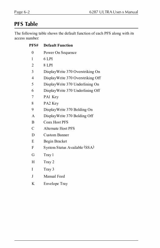
6287 ULTRA User�s ManualPage 6-2
PFS Table
The following table shows the default function of each PFS along with itsaccess number:
PFS# Default Function
0 Power On Sequence
1 6 LPI
2 8 LPI
3 DisplayWrite 370 Overstriking On
4 DisplayWrite 370 Overstriking Off
5 DisplayWrite 370 Underlining On
6 DisplayWrite 370 Underlining Off
7 PA1 Key
8 PA2 Key
9 DisplayWrite 370 Bolding On
A DisplayWrite 370 Bolding Off
B Coax Host PFS
C Alternate Host PFS
D Custom Banner
E Begin Bracket
F System Status Available (SSA)
G Tray 1
H Tray 2
I Tray 3
J Manual Feed
K Envelope Tray

Page 6-3PROGRAMMABLE FUNCTION STRINGS
Accessing PFSs from the Host
All of the ULTRA PFSs may be triggered by the user directly, rather thanby the host application. To force an escape sequence from the coax host,simply key:
¢&n
where ¢ (the Trigger 1 default) is the trigger; an ampersand (&) tells theULTRA to send a PFS to the printer; and n is the number of the PFS tosend. Here are some examples:
¢&0 send the Power On Sequence PFS to the printer
¢&2 set line density to 8 lines per inch
PFSs can be triggered at any appropriate place in the data stream, or thetrigger sequence may be sent as a file print or as a local copy.
Note: If the user intends to trigger PFSs in the data stream of a print job,Option #1 � Column Width should be set to 0 (infinite line length), Option#2 � Lines Per Page should be set to 0 (infinite page length), and Option#15 � Bold Print Emulation should be set to C (none). Otherwise,unpredictable formatting errors could occur. Refer to Section 12 �DisplayWrite 370 Support for more information.
Multiple Function Strings
Programmable Function Strings may be set up so they will automaticallyexecute additional PFSs. By including a plus sign (+) as the last character ina PFS, the ULTRA will send that PFS plus the following PFS to the printer.For example, if PFS 3 is defined as:
[xx][xx][xx]+ (where [xx] represents a hexadecimal pair)
whenever PFS 3 is executed, the contents of both PFS 3 and PFS 4 will besent to the printer.
By including a plus sign (+) and a PFS number as the last two characters ina PFS, the ULTRA will send that PFS plus PFS n to the printer. Forexample, if PFS 2 is defined as:
[xx][xx][xx]+7 (where [xx] represents a hexadecimal pair)
whenever PFS 2 is executed, the contents of both PFS 2 and PFS 7 will besent to the printer.

6287 ULTRA User�s ManualPage 6-4
PFS Descriptions
The following is a complete list of PFSs currently offered. A description ofwhen each PFS is triggered by the host application is included, althoughPFSs can also be triggered by the user at any time.
0 � Power On Sequence
The contents of the Power On Sequence PFS are sent to the printer eachtime the ULTRA is powered on or RESET. The Power On Sequence is alsosent to the printer when a ¢&0 [Trigger 1-ampersand-zero] that the userhas embedded in the data stream is encountered by the ULTRA.
1 � 6 LPI or User-defined
When a host line density command (2B C6 02 nn) is detected and nn is 0C(0Ch = 12/72nds), the contents of this PFS are output to the printer. Note:This command will be seen only in an SCS data stream. The 6 LPI PFS willalso be sent to the printer when a ¢&1 [Trigger 1-ampersand-one] that theuser has embedded in the data stream is encountered by the ULTRA. If theuser is certain that the host never sets line density, the user may programthis PFS for any purpose.
2 � 8 LPI or User-defined
When a host line density command (2B C6 02 nn) is detected and nn is 09(09h = 9/72nds), the contents of this PFS are output to the printer. Note:This command will be seen only in an SCS data stream. The 8 LPI PFS willalso be sent to the printer when a ¢&2 [Trigger 1-ampersand-two] that theuser has embedded in the data stream is encountered by the ULTRA. If theuser is certain that the host never sets line density, the user may programthis PFS for any purpose.
3 � DisplayWrite 370 Overstriking On or User-defined
If a [character-backspace-different character] sequence is detected in thedata stream, this PFS is sent to the printer. Note: This is used only whenOption #15 � Bold Print Emulation is set to (A) 3287 emulation or(B) DisplayWrite 370 emulation. The Overstriking On PFS will also be sentto the printer when a ¢&3 [Trigger 1-ampersand-three] that the user hasembedded in the data stream is encountered by the ULTRA. If the user iscertain that the host never turns on overstriking, or if Option #15 has beenset to (C) None, the user may program this PFS for any purpose.

Page 6-5PROGRAMMABLE FUNCTION STRINGS
4 � DisplayWrite 370 Overstriking Off or User-defined
If overstriking was on previously and a [character-character] sequence isdetected in the data stream, this PFS is sent to the printer. Note: This is usedonly when Option #15 � Bold Print Emulation is set to (A) 3287 emulationor (B) DisplayWrite 370 emulation. The Overstriking Off PFS will also besent to the printer when a ¢&4 [Trigger 1-ampersand-four] that the userhas embedded in the data stream is encountered by the ULTRA. If the useris certain that the host never turns off overstriking, or if Option #15 hasbeen set to (C) None, the user may program this PFS for any purpose.
5 � DisplayWrite 370 Underlining On or User-defined
If a [character-backspace-underline] sequence is detected in the datastream, this PFS is sent to the printer. Note: This is used only when Option#15 � Bold Print Emulation is set to (A) 3287 emulation or (B) Display-Write 370 emulation. The Underlining On PFS will also be sent to theprinter when a ¢&5 [Trigger 1-ampersand-five] that the user has embeddedin the data stream is encountered by the ULTRA. If the user is certain thatthe host never turns on underlining, or if Option #15 has been set to (C)None, the user may program this PFS for any purpose.
6 � DisplayWrite 370 Underlining Off or User-defined
If underlining was on previously and a [character-non-backspace]sequence is detected in the data stream, this PFS is sent to the printer. Note:This is used only when Option #15 � Bold Print Emulation is set to (A)3287 emulation or (B) DisplayWrite 370 emulation. The Underlining OffPFS will also be sent to the printer when a ¢&6 [Trigger 1-ampersand-six]that the user has embedded in the data stream is encountered by theULTRA. If the user is certain that the host never turns off underlining, or ifOption #15 has been set to (C) None, the user may program this PFS forany purpose.
7 � PA1 Key (User-defined)
The contents of the PA1 Key PFS are sent to the printer when a ¢&7[Trigger 1-ampersand-seven] that the user has embedded in the data streamis encountered by the ULTRA. If Option #9 � PA Key Usage is set to (B)PFS, the PA1 Key PFS will be sent to the printer each time the PA1 Key onthe front panel is pressed. The user may program this PFS for any purpose.
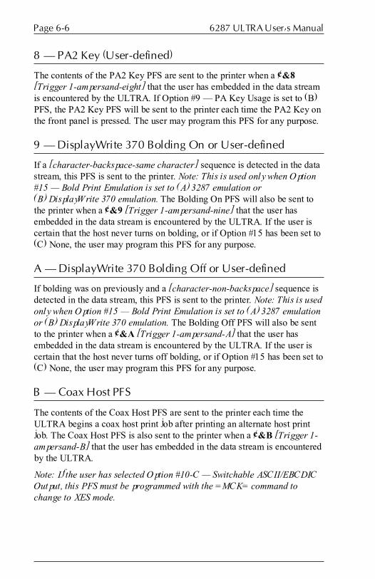
6287 ULTRA User�s ManualPage 6-6
8 � PA2 Key (User-defined)
The contents of the PA2 Key PFS are sent to the printer when a ¢&8[Trigger 1-ampersand-eight] that the user has embedded in the data streamis encountered by the ULTRA. If Option #9 � PA Key Usage is set to (B)PFS, the PA2 Key PFS will be sent to the printer each time the PA2 Key onthe front panel is pressed. The user may program this PFS for any purpose.
9 � DisplayWrite 370 Bolding On or User-defined
If a [character-backspace-same character] sequence is detected in the datastream, this PFS is sent to the printer. Note: This is used only when Option#15 � Bold Print Emulation is set to (A) 3287 emulation or(B) DisplayWrite 370 emulation. The Bolding On PFS will also be sent tothe printer when a ¢&9 [Trigger 1-ampersand-nine] that the user hasembedded in the data stream is encountered by the ULTRA. If the user iscertain that the host never turns on bolding, or if Option #15 has been set to(C) None, the user may program this PFS for any purpose.
A � DisplayWrite 370 Bolding Off or User-defined
If bolding was on previously and a [character-non-backspace] sequence isdetected in the data stream, this PFS is sent to the printer. Note: This is usedonly when Option #15 � Bold Print Emulation is set to (A) 3287 emulationor (B) DisplayWrite 370 emulation. The Bolding Off PFS will also be sentto the printer when a ¢&A [Trigger 1-ampersand-A] that the user hasembedded in the data stream is encountered by the ULTRA. If the user iscertain that the host never turns off bolding, or if Option #15 has been set to(C) None, the user may program this PFS for any purpose.
B � Coax Host PFS
The contents of the Coax Host PFS are sent to the printer each time theULTRA begins a coax host print job after printing an alternate host printjob. The Coax Host PFS is also sent to the printer when a ¢&B [Trigger 1-ampersand-B] that the user has embedded in the data stream is encounteredby the ULTRA.
Note: If the user has selected Option #10-C � Switchable ASCII/EBCDICOutput, this PFS must be programmed with the =MCK= command tochange to XES mode.

Page 6-7PROGRAMMABLE FUNCTION STRINGS
C � Alternate Host PFS
The contents of the Alternate Host PFS are sent to the printer each time theULTRA begins an alternate host print job after printing a coax host printjob. The Alternate Host PFS is also sent to the printer when a ¢&C[Trigger 1-ampersand-C] that the user has embedded in the data stream isencountered by the ULTRA.
Note: If the user has selected Option #10-C � Switchable ASCII/EBCDICOutput, this PFS must be programmed with the =MCK= command tochange to HP PCL emulation mode.
D � Custom Banner
The contents of the custom banner are printed as a text header on AutoBuffer Dump reports. The custom banner is entered as text (not ashexadecimal), and a maximum of 76 characters is allowed. Refer to Section4 � Troubleshooting for more information on Auto Buffer Dumps.
E � Begin Bracket
The contents of the Begin Bracket PFS are sent to the printer each time theULTRA begins a bracketed coax host print job. The Begin Bracket PFS isalso sent to the printer when a ¢&E [Trigger 1-ampersand-E] that the userhas embedded in the data stream is encountered by the ULTRA.
F � System Status Available (SSA)
The contents of the System Status Available PFS are sent to the printer eachtime the ULTRA receives an SSA command from the coax host. The SSAPFS is also sent to the printer when a ¢&F [Trigger 1-ampersand-F] thatthe user has embedded in the data stream is encountered by the ULTRA.
G � Tray 1 or User-defined
In SCS data streams, the contents of the Tray 1 PFS are sent to the printereach time the ULTRA receives a Tray 1 selection command from the coaxhost. The Tray 1 PFS is also sent to the printer when a ¢&G [Trigger 1-ampersand-G] that the user has embedded in the data stream is encounteredby the ULTRA. If the user is certain that this tray selection command isnever sent by the host application, the user may program this PFS for anypurpose.
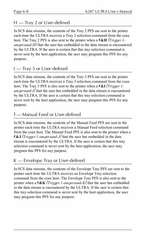
6287 ULTRA User�s ManualPage 6-8
H � Tray 2 or User-defined
In SCS data streams, the contents of the Tray 2 PFS are sent to the printereach time the ULTRA receives a Tray 2 selection command from the coaxhost. The Tray 2 PFS is also sent to the printer when a ¢&H [Trigger 1-ampersand-H] that the user has embedded in the data stream is encounteredby the ULTRA. If the user is certain that this tray selection command isnever sent by the host application, the user may program this PFS for anypurpose.
I � Tray 3 or User-defined
In SCS data streams, the contents of the Tray 3 PFS are sent to the printereach time the ULTRA receives a Tray 3 selection command from the coaxhost. The Tray 3 PFS is also sent to the printer when a ¢&I [Trigger 1-ampersand-I] that the user has embedded in the data stream is encounteredby the ULTRA. If the user is certain that this tray selection command isnever sent by the host application, the user may program this PFS for anypurpose.
J � Manual Feed or User-defined
In SCS data streams, the contents of the Manual Feed PFS are sent to theprinter each time the ULTRA receives a Manual Feed selection commandfrom the coax host. The Manual Feed PFS is also sent to the printer when a¢&J [Trigger 1-ampersand-J] that the user has embedded in the datastream is encountered by the ULTRA. If the user is certain that this trayselection command is never sent by the host application, the user mayprogram this PFS for any purpose.
K � Envelope Tray or User-defined
In SCS data streams, the contents of the Envelope Tray PFS are sent to theprinter each time the ULTRA receives an Envelope Tray selectioncommand from the coax host. The Envelope Tray PFS is also sent to theprinter when a ¢&K [Trigger 1-ampersand-K] that the user has embeddedin the data stream is encountered by the ULTRA. If the user is certain thatthis tray selection command is never sent by the host application, the usermay program this PFS for any purpose.

TRANSLATE TABLES
General Information
The data stream from the coax host or alternate host is not sent directlythrough the ULTRA to the attached printer. Rather, all characters must firstpass through the appropriate character code translation table, even if theprinter uses the same data format as the source device.
If the data formats of the two devices are different, a translation table isselected that will convert the data from one format to another. The mostbasic function of the ULTRA is to convert EBCDIC (or coax host) data toASCII data one byte at a time. Each translate table has 256 entriesnumbered 00 to FF. When a character is received by the ULTRA, thecorresponding character from the appropriate translate table is substituted,and that value is sent to the printer.
The ULTRA uses twelve translate tables that can be modified by the user(although five are reserved). The tables are listed here with their tableaccess number or letter:
Table # Description
1 DSC to ASCII
2 SCS to ASCII
3 ASCII to ASCII (also used for the configuration report)
4 DSC to EBCDIC
5 SCS to EBCDIC
6 ASCII to EBCDIC (also used for the configuration report)
7 DSC to APL
8 SCS to APL
9 Reserved � SCS font download table
A Reserved � DSC font download table
B Reserved � not used
C Reserved � not used
Translate tables can be modified from the coax host or from an alternatehost. Refer to Section 9 � Coax Host Configuration and Section 10 �Alternate Host Configuration for information.
Note: Modifying translate tables should be attempted only by advancedusers with a clear understanding of how the translate tables function.
SECTION 7

6287 ULTRA User�s ManualPage 7-2
Translate Table Selection
The ULTRA determines the appropriate translation table to use based uponboth the user�s configuration of the ULTRA and the data stream it receives.
The output (ASCII or EBCDIC) is determined by the user�s configurationof the ULTRA using configuration Option #10. Option #11 determines ifAPL output is supported for DSC data streams when Option #10 isconfigured for ASCII output and when Option #20 is configured for EABsupport.
The input is detected by analysis of the data stream by the ULTRA. Whenan EBCDIC character from the host arrives at the ULTRA, it may be eitherDSC or SCS data. See Section 14 � SCS Data Streams and Section 15 �DSC Data Streams for more information. The table to be used is selected bythe ULTRA by combining the information from the input and outputvariables as follows:
Input:
� If the data stream is ASCII (from an alternate host), the appropriatetranslate table is 3 (for ASCII output) or 6 (for EBCDIC output).
� If the coax host data stream is in DSC format, the appropriatetranslate table is 1 (for ASCII output), 4 (EBCDIC output) or 7 (APLoutput).
� If the coax host data stream is in SCS format, the appropriatetranslate table is 2 (for ASCII output), 5 (EBCDIC output) or 8 (APLoutput).
Output:
� If the ULTRA is configured for ASCII output, the appropriatetranslate table is 1, 2 or 3.
� If the ULTRA is configured for EBCDIC output, the appropriatetranslate table is 4, 5 or 6.
� If the ULTRA is configured for APL output (refer to Options 10, 11and 20), the appropriate translate table is 7 or 8.
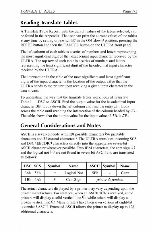
Page 7-3TRANSLATE TABLES
Reading Translate Tables
A Translate Table Report, with the default values of the tables selected, canbe found in the Appendix. The user can print the current values of the tablesat any time by setting dip switch B7 in the ON (down) position, pressing theRESET button and then the CANCEL button on the ULTRA front panel.
The left column of each table is a series of numbers and letters representingthe most significant digit of the hexadecimal input character received by theULTRA. The top row of each table is a series of numbers and lettersrepresenting the least significant digit of the hexadecimal input characterreceived by the ULTRA.
The intersection in the table of the most significant and least significantdigits of the input character is the location of the output value that theULTRA sends to the printer upon receiving a given input character in thedata stream.
To understand the way that the translate tables work, look at TranslateTable 1 � DSC to ASCII. Find the output value for the hexadecimal inputcharacter '3B.' Look down the left column and find the entry �3.� Lookacross the table until reaching the intersection of the column headed by �B.�The table shows that the output value for the input value of '3B' is '7E.'
General Considerations and Notes
ASCII is a seven-bit code with 128 possible characters (96 printablecharacters and 32 control characters). The ULTRA translates incoming SCSand DSC (EBCDIC) characters directly into the appropriate seven-bitASCII character whenever possible. Two IBM characters, the cent sign (¢)and the logical not (¬) are not found in seven-bit ASCII and are translatedas follows:
DSC SCS Symbol Name ASCII Symbol Name
36h 5Fh ¬ Logical Not 5Eh ^ Caret
1Bh 4Ah ¢ Cent Sign printer dependent
The actual characters displayed by a printer may vary depending upon theprinter manufacturer. For instance, when an ASCII 7Ch is received, someprinters will display a solid vertical line (|), while others will display abroken vertical line (¦). Many printers have their own version of eight-bit(extended) ASCII. Extended ASCII allows the printer to display up to 128additional characters.

6287 ULTRA User�s ManualPage 7-4
Functions
Some translate tables perform functions in addition to performing charactertranslation. Each input hexadecimal character that performs a function isfirst translated into 05h. The function that is performed by the 05h characteris determined by the location of the 05h in the table and is indicated by thecode beneath each 05h entry in the table. Each function is listed below,including a description for each function that does not perform in a standardmanner.
� EM (End of Message)
� FF (SCS or DSC Form Feed): Dependent upon the setting of Option #2 �Lines Per Page. If set to 0 (infinite page length), the ULTRA will send aform feed whenever a form feed is received. If set to a non-zero value, theULTRA will output CR/LF until the lines per page value is reached.
� NL (New Line)
� CR (Carriage Return)
� VCS (SCS Vertical Channel Select)
� HT (SCS Horizontal Tab): Converted into the appropriate number ofspaces to reach the next horizontal tab position.
� LF (Line Feed)
� TRN (Transparency)
� BS (Backspace)
� ESC (SCS Escape): When the SCS control sequence prefix 2Bh isreceived, it indicates the beginning of an SCS format command streamsuch as SHF, SVF, SLD, etc.
� VT (SCS Vertical Tab): Converted into the appropriate number of linefeeds to reach the next vertical tab position.
� GE (Graphic Escape)
� IRS (SCS Interchange Record Separator)
� NULL (SCS or DSC Null): Output to the printer as a space.
� SP (Space)
� SA (SCS Set Attribute)
� ¢ (Trigger 1 character): Processing of the Trigger 1 character dependsupon the setting of Option #30 � Pseudo Transparency Mode Selection.
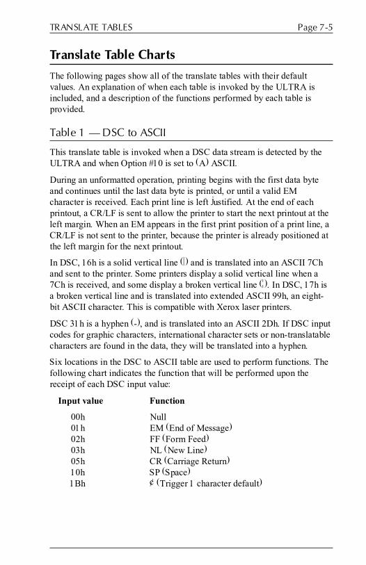
Page 7-5TRANSLATE TABLES
Translate Table Charts
The following pages show all of the translate tables with their defaultvalues. An explanation of when each table is invoked by the ULTRA isincluded, and a description of the functions performed by each table isprovided.
Table 1 � DSC to ASCII
This translate table is invoked when a DSC data stream is detected by theULTRA and when Option #10 is set to (A) ASCII.
During an unformatted operation, printing begins with the first data byteand continues until the last data byte is printed, or until a valid EMcharacter is received. Each print line is left justified. At the end of eachprintout, a CR/LF is sent to allow the printer to start the next printout at theleft margin. When an EM appears in the first print position of a print line, aCR/LF is not sent to the printer, because the printer is already positioned atthe left margin for the next printout.
In DSC, 16h is a solid vertical line (|) and is translated into an ASCII 7Chand sent to the printer. Some printers display a solid vertical line when a7Ch is received, and some display a broken vertical line (¦). In DSC, 17h isa broken vertical line and is translated into extended ASCII 99h, an eight-bit ASCII character. This is compatible with Xerox laser printers.
DSC 31h is a hyphen (-), and is translated into an ASCII 2Dh. If DSC inputcodes for graphic characters, international character sets or non-translatablecharacters are found in the data, they will be translated into a hyphen.
Six locations in the DSC to ASCII table are used to perform functions. Thefollowing chart indicates the function that will be performed upon thereceipt of each DSC input value:
Input value Function
00h Null01h EM (End of Message)02h FF (Form Feed)03h NL (New Line)05h CR (Carriage Return)10h SP (Space)1Bh ¢ (Trigger 1 character default)

6287 ULTRA User�s ManualPage 7-6
Table 1 � DSC to ASCII
LS 0 1 2 3 4 5 6 7 8 9 10 11 12 13 14 15
MS 0 1 2 3 4 5 6 7 8 9 A B C D E F
00 0 05 05 05 05 2D 05 2D 2D 3E 3C 5B 5D 29 28 7D 7BNULL EM FF NL - CR - - ^ < [ ] ) ( } {
16 1 05 3D 27 22 2F 5C 7C 99 3F 21 24 05 2D 2D 2D 2DSP = ' " / \ | ¦ ? ! $ ¢ - - - -
32 2 30 31 32 33 34 35 36 37 38 39 2D 15 23 40 25 5F0 1 2 3 4 5 6 7 8 9 - # @ % _
48 3 26 2D 2E 2C 3A 2B 5E 2D 2D 2D 5E 7E 2D 60 27 2D& - . , : + ^ - - - ^ ~ - ` ' -
64 4 2D 2D 2D 2D 2D 2D 2D 2D 2D 2D 2D 2D 2D 2D 2D 2D- - - - - - - - - - - - - - - -
80 5 2D 2D 2D 2D 2D 2D 2D 2D 2D 2D 2D 2D 2D 2D 2D 2D- - - - - - - - - - - - - - - -
96 6 2D 2D 2D 2D 2D 2D 2D 2D 2D 2D 2D 2D 2D 2D 2D 2D- - - - - - - - - - - - - - - -
112 7 2D 2D 2D 2D 2D 2D 2D 2D 2D 2D 2D 2D 2D 2D 2D 2D- - - - - - - - - - - - - - - -
128 8 61 62 63 64 65 66 67 68 69 6A 6B 6C 6D 6E 6F 70a b c d e f g h i j k l m n o p
144 9 71 72 73 74 75 76 77 78 79 7A 2D 2D 2D 2D 2D 2Dq r s t u v w x y z - - - - - -
160 A 41 42 43 44 45 46 47 48 49 4A 4B 4C 4D 4E 4F 50A B C D E F G H I J K L M N O P
176 B 51 52 53 54 55 56 57 58 59 5A 2D 2D 2D 2D 3B 2AQ R S T U V W X Y Z - - - - ; *
192 C 20 20 20 20 20 20 20 20 20 20 20 20 20 20 20 20SP SP SP SP SP SP SP SP SP SP SP SP SP SP SP SP
208 D 20 20 20 20 20 20 20 20 20 20 20 20 20 20 20 20SP SP SP SP SP SP SP SP SP SP SP SP SP SP SP SP
224 E 20 20 20 20 20 20 20 20 20 20 20 20 20 20 20 20SP SP SP SP SP SP SP SP SP SP SP SP SP SP SP SP
240 F 20 20 20 20 20 20 20 20 20 20 20 20 20 20 20 20SP SP SP SP SP SP SP SP SP SP SP SP SP SP SP SP
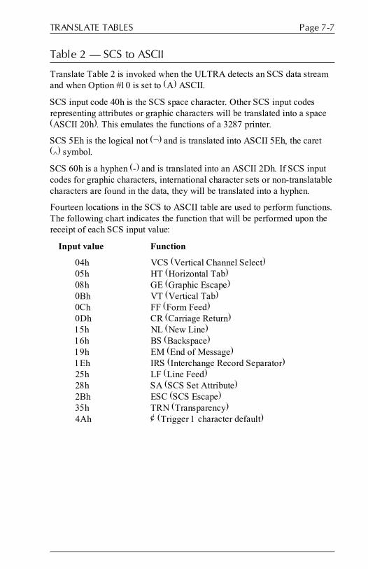
Page 7-7TRANSLATE TABLES
Table 2 � SCS to ASCII
Translate Table 2 is invoked when the ULTRA detects an SCS data streamand when Option #10 is set to (A) ASCII.
SCS input code 40h is the SCS space character. Other SCS input codesrepresenting attributes or graphic characters will be translated into a space(ASCII 20h). This emulates the functions of a 3287 printer.
SCS 5Eh is the logical not (¬) and is translated into ASCII 5Eh, the caret(^) symbol.
SCS 60h is a hyphen (-) and is translated into an ASCII 2Dh. If SCS inputcodes for graphic characters, international character sets or non-translatablecharacters are found in the data, they will be translated into a hyphen.
Fourteen locations in the SCS to ASCII table are used to perform functions.The following chart indicates the function that will be performed upon thereceipt of each SCS input value:
Input value Function
04h VCS (Vertical Channel Select)05h HT (Horizontal Tab)08h GE (Graphic Escape)0Bh VT (Vertical Tab)0Ch FF (Form Feed)0Dh CR (Carriage Return)15h NL (New Line)16h BS (Backspace)19h EM (End of Message)1Eh IRS (Interchange Record Separator)25h LF (Line Feed)28h SA (SCS Set Attribute)2Bh ESC (SCS Escape)35h TRN (Transparency)4Ah ¢ (Trigger 1 character default)
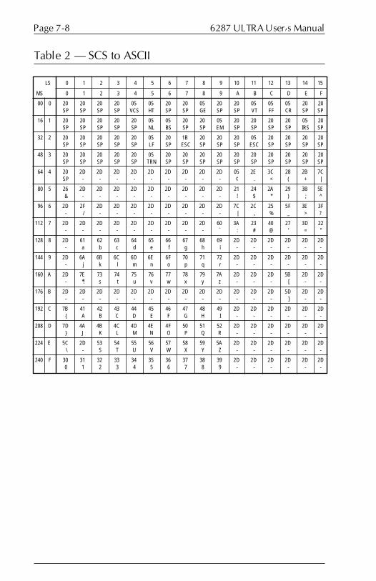
6287 ULTRA User�s ManualPage 7-8
Table 2 � SCS to ASCII
LS 0 1 2 3 4 5 6 7 8 9 10 11 12 13 14 15
MS 0 1 2 3 4 5 6 7 8 9 A B C D E F
00 0 20 20 20 20 05 05 20 20 05 20 20 05 05 05 20 20SP SP SP SP VCS HT SP SP GE SP SP VT FF CR SP SP
16 1 20 20 20 20 20 05 05 20 20 05 20 20 20 20 05 20SP SP SP SP SP NL BS SP SP EM SP SP SP SP IRS SP
32 2 20 20 20 20 20 05 20 1B 20 20 20 05 20 20 20 20SP SP SP SP SP LF SP ESC SP SP SP ESC SP SP SP SP
48 3 20 20 20 20 20 05 20 20 20 20 20 20 20 20 20 20SP SP SP SP SP TRN SP SP SP SP SP SP SP SP SP SP
64 4 20 2D 2D 2D 2D 2D 2D 2D 2D 2D 05 2E 3C 28 2B 7CSP - - - - - - - - - ¢ . < ( + |
80 5 26 2D 2D 2D 2D 2D 2D 2D 2D 2D 21 24 2A 29 3B 5E& - - - - - - - - - ! $ * ) ; ^
96 6 2D 2F 2D 2D 2D 2D 2D 2D 2D 2D 7C 2C 25 5F 3E 3F- / - - - - - - - - | , % _ > ?
112 7 2D 2D 2D 2D 2D 2D 2D 2D 2D 60 3A 23 40 27 3D 22- - - - - - - - - ` : # @ ' = "
128 8 2D 61 62 63 64 65 66 67 68 69 2D 2D 2D 2D 2D 2D- a b c d e f g h i - - - - - -
144 9 2D 6A 6B 6C 6D 6E 6F 70 71 72 2D 2D 2D 2D 2D 2D- j k l m n o p q r - - - - - -
160 A 2D 7E 73 74 75 76 77 78 79 7A 2D 2D 2D 5B 2D 2D- *! s t u v w x y z - - - [ - -
176 B 2D 2D 2D 2D 2D 2D 2D 2D 2D 2D 2D 2D 2D 5D 2D 2D- - - - - - - - - - - - - ] - -
192 C 7B 41 42 43 44 45 46 47 48 49 2D 2D 2D 2D 2D 2D{ A B C D E F G H I - - - - - -
208 D 7D 4A 4B 4C 4D 4E 4F 50 51 52 2D 2D 2D 2D 2D 2D} J K L M N O P Q R - - - - - -
224 E 5C 2D 53 54 55 56 57 58 59 5A 2D 2D 2D 2D 2D 2D\ - S T U V W X Y Z - - - - - -
240 F 30 31 32 33 34 35 36 37 38 39 2D 2D 2D 2D 2D 2D0 1 2 3 4 5 6 7 8 9 - - - - - -

Page 7-9TRANSLATE TABLES
Translate Table 3 � ASCII to ASCII
Translate Table 3 is a pass-through table used to send alternate host data toa printer using the ASCII character set. It is invoked when the ULTRAdetects an ASCII data stream and when Option #10 is set to (A) ASCII or(C) Switchable.
This table is also used to pass through the configuration report (created inASCII) to an ASCII printer when Option #10 is set to (A) ASCII. If thistable is modified by the user, the configuration report sent to the printer willbe affected.

6287 ULTRA User�s ManualPage 7-10
Translate Table 3 � ASCII to ASCII
LS 0 1 2 3 4 5 6 7 8 9 10 11 12 13 14 15
MS 0 1 2 3 4 5 6 7 8 9 A B C D E F
00 0 00 01 02 03 04 05 06 07 08 09 0A 0B 0C 0D 0E OFNULL SOH STX ETX EOT ENQ ACK BEL BS HT LF VT FF CR SO SI
16 1 10 11 12 13 14 15 16 17 18 19 1A 1B 1C 1D 1E 1FDLE DC1 DC2 DC3 DC4 NAK SYN ETB CAN EM SUB ESC FS GS RS US
32 2 20 21 22 23 24 25 26 27 28 29 2A 2B 2C 2D 2E 2FSP ! " # $ % & ' ( ) * + , - . /
48 3 30 31 32 33 34 35 36 37 38 39 3A 3B 3C 3D 3E 3F0 1 2 3 4 5 6 7 8 9 : ; < = > ?
64 4 40 41 42 43 44 45 46 47 48 49 4A 4B 4C 4D 4E 4F@ A B C D E F G H I J K L M N O
80 5 50 51 52 53 54 55 56 57 58 59 5A 5B 5C 5D 5E 5FP Q R S T U V W X Y Z [ \ ] ^ _
96 6 60 61 62 63 64 65 66 67 68 69 6A 6B 6C 6D 6E 6F` a b c d e f g h i j k l m n o
112 7 70 71 72 73 74 75 76 77 78 79 7A 7B 7C 7D 7E 7Fp q r s t u v w x y z { | } ~ DEL
128 8 80 81 82 83 84 85 86 87 88 89 8A 8B 8C 8D 8E 8F
144 9 90 91 92 93 94 95 96 97 98 99 9A 9B 9C 9D 9E 9F
160 A A0 A1 A2 A3 A4 A5 A6 A7 A8 A9 AA AB AC AD AE AF
176 B B0 B1 B2 B3 B4 B5 B6 B7 B8 B9 BA BB BC BD BE BF
192 C C0 C1 C2 C3 C4 C5 C6 C7 C8 C9 CA CB CC CD CE CF
208 D D0 D1 D2 D3 D4 D5 D6 D7 D8 D9 DA DB DC DD DE DF
224 E E0 E1 E2 E3 E4 E5 E6 E7 E8 E9 EA EB EC ED EE EF
240 F F0 F1 F2 F3 F4 F5 F6 F7 F8 F9 FA FB FC FD FE FF
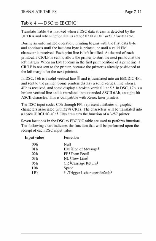
Page 7-11TRANSLATE TABLES
Table 4 � DSC to EBCDIC
Translate Table 4 is invoked when a DSC data stream is detected by theULTRA and when Option #10 is set to (B) EBCDIC or (C) Switchable.
During an unformatted operation, printing begins with the first data byteand continues until the last data byte is printed, or until a valid EMcharacter is received. Each print line is left justified. At the end of eachprintout, a CR/LF is sent to allow the printer to start the next printout at theleft margin. When an EM appears in the first print position of a print line, aCR/LF is not sent to the printer, because the printer is already positioned atthe left margin for the next printout.
In DSC, 16h is a solid vertical line (|) and is translated into an EBCDIC 4Fhand sent to the printer. Some printers display a solid vertical line when a4Fh is received, and some display a broken vertical line (¦). In DSC, 17h is abroken vertical line and is translated into extended ASCII 6Ah, an eight-bitASCII character. This is compatible with Xerox laser printers.
The DSC input codes C0h through FFh represent attributes or graphiccharacters associated with 3278 CRTs. The characters will be translated intoa space (EBCDIC 40h). This emulates the function of a 3287 printer.
Seven locations in the DSC to EBCDIC table are used to perform functions.The following chart indicates the function that will be performed upon thereceipt of each DSC input value:
Input value Function
00h Null01h EM (End of Message)02h FF (Form Feed)03h NL (New Line)05h CR (Carriage Return)10h Space1Bh ¢ (Trigger 1 character default)

6287 ULTRA User�s ManualPage 7-12
Table 4 � DSC to EBCDIC
* indicates a superscript character.
LS 0 1 2 3 4 5 6 7 8 9 10 11 12 13 14 15
MS 0 1 2 3 4 5 6 7 8 9 A B C D E F
00 0 05 05 05 05 60 05 ED EE 6E 4C AD BD 5D 4D D0 C0NULL EM FF NL - CR > < [ ] ) ( } {
16 1 05 7E 7D 7F 61 E0 4F 6A 6F 5A 5B 05 43 44 45 46SP = ' " / \ | ¦ ? ! $ ¢
32 2 F0 F1 F2 F3 F4 F5 F6 F7 F8 F9 47 48 7B 7C 6C 6D0 1 2 3 4 5 6 7 8 9 # @ %
48 3 50 60 4B 6B 7A 4E 5F 49 51 52 53 A1 54 79 55 56& - . , : + ~
64 4 57 58 59 62 63 64 65 66 67 68 69 70 CE CF DD DE
80 5 75 76 77 78 80 8A 8B 8C 8D 8E 8F 90 9A 98 9C 9D{ < (* +* ) )*
96 6 9E 9F A0 AA AB AC 41 AE AF B0 B1 B2 B3 B4 B5 B6+ _* 0* 1* 2* 3* 4* 5* 6*
112 7 B7 B8 B9 BA BB BC 42 BE BF CA CB CC CD DF DB DC7* 8* 9*
128 8 81 82 83 84 85 86 87 88 89 91 92 93 94 95 96 97a b c d e f g h i j k l m n o p
144 9 98 99 A2 A3 A4 A5 A6 A7 A8 A9 E1 EA EB EC EF FEq r s t u v w x y z
160 A C1 C2 C3 C4 C5 C6 C7 C8 C9 D1 D2 D3 D4 D5 D6 D7A B C D E F G H I J K L M N O P
176 B D8 D9 E2 E3 E4 E5 E6 E7 E8 E9 FA FB FC FD 5E 5CQ R S T U V W X Y Z ; *
192 C 40 40 40 40 40 40 40 40 40 40 40 40 40 40 40 40SP SP SP SP SP SP SP SP SP SP SP SP SP SP SP SP
208 D 40 40 40 40 40 40 40 40 40 40 40 40 40 40 40 40SP SP SP SP SP SP SP SP SP SP SP SP SP SP SP SP
224 E 40 40 40 40 40 40 40 40 40 40 40 40 40 40 40 40SP SP SP SP SP SP SP SP SP SP SP SP SP SP SP SP
240 F 40 40 40 40 40 40 40 40 40 40 40 40 40 40 40 40SP SP SP SP SP SP SP SP SP SP SP SP SP SP SP SP

Page 7-13TRANSLATE TABLES
Table 5 � SCS to EBCDIC
Translate Table 5 is invoked when an SCS data stream is detected by theULTRA and when Option #10 is set to (B) EBCDIC or (C) Switchable.
Thirteen locations in the SCS to EBCDIC table are used to performfunctions. The following chart indicates the function that will be performedupon the receipt of each SCS input value:
Input value Function
05h HT (Horizontal Tab)08h GE (Graphic Escape)0Bh VT (Vertical Tab)0Ch FF (Form Feed)0Dh CR (Carriage Return)15h NL (New Line)16h BS (Backspace)19h EM (End of Message)1Eh IRS (Interchange Record Separator)25h LF (Line Feed)28h SA (SCS Set Attribute)2Bh ESC (SCS Escape)35h TRN (Transparency)4Ah ¢ (Trigger 1 character default)
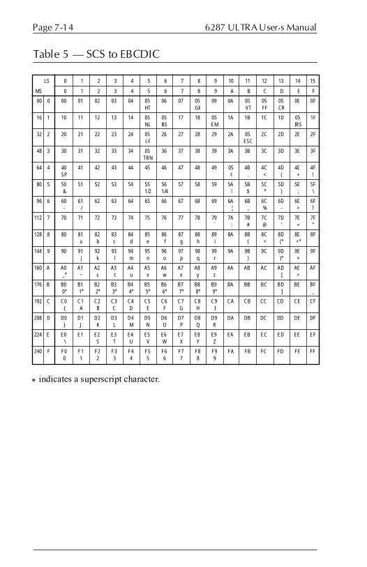
6287 ULTRA User�s ManualPage 7-14
* indicates a superscript character.
Table 5 � SCS to EBCDIC
LS 0 1 2 3 4 5 6 7 8 9 10 11 12 13 14 15
MS 0 1 2 3 4 5 6 7 8 9 A B C D E F
00 0 00 01 02 03 04 05 06 07 05 09 0A 05 05 05 0E 0FHT GE VT FF CR
16 1 10 11 12 13 14 05 05 17 18 05 1A 1B 1C 1D 05 1FNL BS EM IRS
32 2 20 21 22 23 24 05 26 27 28 29 2A 05 2C 2D 2E 2FLF ESC
48 3 30 31 32 33 34 05 36 37 38 39 3A 3B 3C 3D 3E 3FTRN
64 4 40 41 42 43 44 45 46 47 48 49 05 4B 4C 4D 4E 4FSP ¢ . < ( + !
80 5 50 51 52 53 54 55 56 57 58 59 5A 5B 5C 5D 5E 5F& 1/2 1/4 ! $ * ) ; \
96 6 60 61 62 63 64 65 66 67 68 69 6A 6B 6C 6D 6E 6F- / ¦ , % - > ?
112 7 70 71 72 73 74 75 76 77 78 79 7A 7B 7C 7D 7E 7F` : # @ ' = "
128 8 80 81 82 83 84 85 86 87 88 89 8A 8B 8C 8D 8E 8Fa b c d e f g h i ( < (* +*
144 9 90 91 92 93 94 95 96 97 98 99 9A 9B 9C 9D 9E 9Fj k l m n o p q r ) )* +
160 A A0 A1 A2 A3 A4 A5 A6 A7 A8 A9 AA AB AC AD AE AF_* ~ s t u v w x y z [ >
176 B B0 B1 B2 B3 B4 B5 B6 B7 B8 B9 BA BB BC BD BE BF0* 1* 2* 3* 4* 5* 6* 7* 8* 9* ] _
192 C C0 C1 C2 C3 C4 C5 C6 C7 C8 C9 CA CB CC CD CE CF{ A B C D E F G H I
208 D D0 D1 D2 D3 D4 D5 D6 D7 D8 D9 DA DB DC DD DE DF} J K L M N O P Q R
224 E E0 E1 E2 E3 E4 E5 E6 E7 E8 E9 EA EB EC ED EE EF\ S T U V W X Y Z
240 F F0 F1 F2 F3 F4 F5 F6 F7 F8 F9 FA FB FC FD FE FF0 1 2 3 4 5 6 7 8 9

Page 7-15TRANSLATE TABLES
Translate Table 6 � ASCII to EBCDIC
Translate Table 6 is used to convert ASCII alternate host data sent to aprinter using the EBCDIC character set. It is invoked when an ASCII datastream is detected by the ULTRA and when Option #10 is set to (B)EBCDIC.
This table is also used to translate and download the configuration report(created in ASCII) to an EBCDIC printer when Option #10 is set either to(B) EBCDIC or (C) Switchable. If this table is modified by the user, theconfiguration report sent to the printer will be affected.
Input value Function
09h Tab

6287 ULTRA User�s ManualPage 7-16
Translate Table 6 � ASCII to EBCDIC
LS 0 1 2 3 4 5 6 7 8 9 10 11 12 13 14 15
MS 0 1 2 3 4 5 6 7 8 9 A B C D E F
00 0 00 01 02 03 37 2D 15 2F 16 05 25 0B 0C 0D 0E 0FCR
16 1 10 11 12 13 3C 3D 32 26 18 19 3F 27 22 1D 1E 1F
32 2 40 5A 7F 7B 5B 6C 50 7D 4D 5D 5C 4E 6B 60 4B 61SP ! " # $ % & ' ( ) * + , - /
48 3 F0 F1 F2 F3 F4 F5 F6 F7 F8 F9 7A 5E 4C 7E 6E 6F 0 1 2 3 4 5 6 7 8 9 : ; < = > ?
64 4 7C C1 C2 C3 C4 C5 C6 C7 C8 C9 D1 D2 D3 D4 D5 D6@ A B C D E F G H I J K L M N O
80 5 D7 D8 D9 E2 E3 E4 E5 E6 E7 E8 E9 AD E0 BD B5 6DP Q R S T U V W X Y Z [ \ ] ^ _
96 6 79 81 82 83 84 85 86 87 88 89 91 92 93 94 95 96` a b c d e f g h i j k l m n o
112 7 97 98 99 A2 A3 A4 A5 A6 A7 A8 A9 C0 4F D0 A1 07p q r s t u v w x y z { ! } ~
128 8 60 60 60 60 60 60 60 60 60 60 60 60 60 60 60 60- - - - - - - - - - - - - - - -
144 9 60 60 60 60 60 60 60 60 60 60 60 60 60 60 60 60- - - - - - - - - - - - - - - -
160 A 60 60 60 60 60 60 60 60 60 60 60 60 60 60 60 60- - - - - - - - - - - - - - - -
176 B 60 60 60 60 60 60 60 60 60 60 60 60 60 60 60 60- - - - - - - - - - - - - - - -
192 C 60 60 60 60 60 60 60 60 60 60 60 60 60 60 60 60- - - - - - - - - - - - - - - -
208 D 60 60 60 60 60 60 60 60 60 60 60 60 60 60 60 60- - - - - - - - - - - - - - - -
224 E 60 60 60 60 60 60 60 60 60 60 60 60 60 60 60 60- - - - - - - - - - - - - - - -
240 F 60 60 60 60 60 60 60 60 60 60 60 60 60 60 60 60- - - - - - - - - - - - - - - -

Page 7-17TRANSLATE TABLES
Table 7 � DSC to ASCII APL
This table is invoked by the ULTRA when a DSC data stream is detected bythe ULTRA and when Option #10 is set to (A) ASCII, Option #11 is set to�Yes� and Option #20 is set either to (B) 2K with EAB or (D) 4K withEAB.
Five locations in the DSC to ASCII APL table are used to performfunctions. The following chart indicates the function that will be performedupon the receipt of each DSC input value:
Input value Function
00h Null01h EM (End of Message)02h FF (Form Feed)03h NL (New Line)05h CR (Carriage Return)
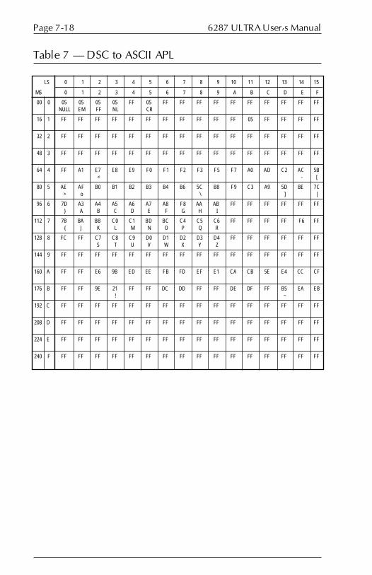
6287 ULTRA User�s ManualPage 7-18
Table 7 � DSC to ASCII APL
LS 0 1 2 3 4 5 6 7 8 9 10 11 12 13 14 15
MS 0 1 2 3 4 5 6 7 8 9 A B C D E F
00 0 05 05 05 05 FF 05 FF FF FF FF FF FF FF FF FF FFNULL EM FF NL CR
16 1 FF FF FF FF FF FF FF FF FF FF FF 05 FF FF FF FF
32 2 FF FF FF FF FF FF FF FF FF FF FF FF FF FF FF FF
48 3 FF FF FF FF FF FF FF FF FF FF FF FF FF FF FF FF
64 4 FF A1 E7 E8 E9 F0 F1 F2 F3 F5 F7 A0 AD C2 AC 5B< - [
80 5 AE AF B0 B1 B2 B3 B4 B6 5C B8 F9 C3 A9 5D BE 7C> o \ ] |
96 6 7D A3 A4 A5 A6 A7 A8 F8 AA AB FF FF FF FF FF FF} A B C D E F G H I
112 7 7B BA BB C0 C1 BD BC C4 C5 C6 FF FF FF FF F6 FF{ J K L M N O P Q R
128 8 FC FF C7 C8 C9 D0 D1 D2 D3 D4 FF FF FF FF FF FFS T U V W X Y Z
144 9 FF FF FF FF FF FF FF FF FF FF FF FF FF FF FF FF
160 A FF FF E6 9B ED EE FB FD EF E1 CA CB 5E E4 CC CF
176 B FF FF 9E 21 FF FF DC DD FF FF DE DF FF B5 EA EB! ~
192 C FF FF FF FF FF FF FF FF FF FF FF FF FF FF FF FF
208 D FF FF FF FF FF FF FF FF FF FF FF FF FF FF FF FF
224 E FF FF FF FF FF FF FF FF FF FF FF FF FF FF FF FF
240 F FF FF FF FF FF FF FF FF FF FF FF FF FF FF FF FF
FRONT PANEL CONFIGURATION
General Information
The ULTRA front panel can be used to set the most-used parameters of thegeneral configuration options. Due to the use of non-volatile, battery-backed RAM, the configuration changes will be stored in the ULTRA evenwhen it is powered off.
To make changes to the general configuration from the ULTRA front panel,make certain that the power is ON. Set dip switch B8 in the ON (down)position, then press the RESET button on the front panel. This will placethe ULTRA in front panel configuration mode. When the ULTRA is infront panel configuration mode, POWER is the only status indicator lightthat is lit on the front panel.
Now press the four-key sequence for the menu option to be changed. If theentry is valid, all of the status light will come on. If the entry is invalid, allof the status lights will flash until the entry is cleared by pressing theRESET button. Continue making other changes with the four-keysequences until the ULTRA is properly configured.
To exit front panel configuration mode, set dip switch B8 in the OFF (up)position, then press the RESET button. The status indicator lights willconfirm that the unit is in normal operating mode. To verify the changes,press the TEST button to print out the new configuration.
Translate tables and PFS definitions can be modified only via a coax hostterminal or via an alternate host. Refer to Section 9 � Coax HostConfiguration and Section 10 � Alternate Host Configuration forinformation on modifying translate tables and PFSs.
SECTION 8

6287 ULTRA User�s ManualPage 8-2
Front Panel Key Sequences
The following charts indicate the front panel key sequences used forchanging general configuration option parameters.
Note: A �D� in the box in the upper left corner indicates the default settingfor each option.
Reset All Configuration Options to Defaults
Reset all options to factory defaults
RESET PA1 PA1 PA1
Option 1 � Column Width
D Option 1-132: Column width = 132
RESET PA1
Option 1-0: Column width = 0 (infinite line length)
RESET PA1
PA1 PA2
Option 1-255: Column width = 255
RESET PA2
LINE FEED
PA1
PA1 PA1

Page 8-3FRONT PANEL CONFIGURATION
Option 2 � Lines Per Page
D Option 2-0: Lines per page = 0 (infinite page length)
RESET PA1
Option 2-66: Lines per page = 66
RESET PA1
PA1
TESTPA1
HOLD PRINT
Option 3 � Line Spacing
D Option 3-1: Line spacing = 1
RESET PA1
Option 3-2: Line spacing = 2
RESET PA1
PA1
FORM FEED
PA1
CANCEL
Option 4 � Local Copy Null Line Suppression
D Option 4-Y: Null line suppression = YES
RESET PA1
Option 4-N: Null line suppression = NO
RESET PA1
PA1
PA2
ENABLE PRINT
PA1
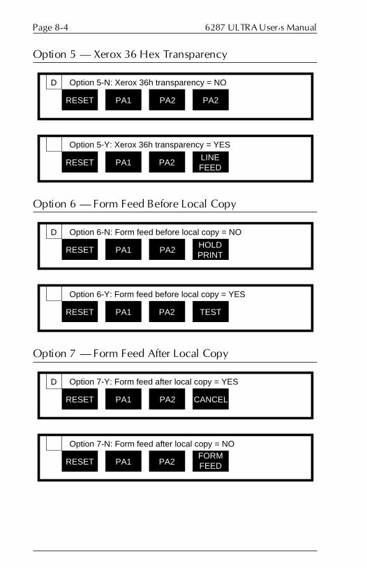
6287 ULTRA User�s ManualPage 8-4
Option 5 � Xerox 36 Hex Transparency
D Option 5-N: Xerox 36h transparency = NO
RESET PA1 PA2
Option 5-Y: Xerox 36h transparency = YES
RESET PA1LINE FEED
PA2
PA2
Option 6 � Form Feed Before Local Copy
D Option 6-N: Form feed before local copy = NO
RESET PA1
Option 6-Y: Form feed before local copy = YES
RESET PA1
HOLD PRINT
PA2
PA2 TEST
Option 7 � Form Feed After Local Copy
D Option 7-Y: Form feed after local copy = YES
RESET PA1
Option 7-N: Form feed after local copy = NO
RESET PA1
PA2
PA2FORM FEED
CANCEL

Page 8-5FRONT PANEL CONFIGURATION
Option 8 � New Line Order
D Option 8-A: New line = CR/LF
RESET PA1
Option 8-B: New line = LF/CR
RESET PA1
PA2
PA1LINE FEED
ENABLE PRINT
Option 9 � PA Key Usage
D Option 9-A: PA Key = Normal
RESET PA1
Option 9-B: PA Key = PFS
RESET PA1
PA2
LINE FEED
LINE FEED
LINE FEED
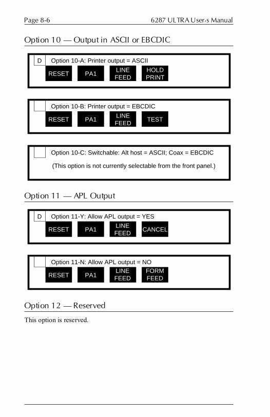
6287 ULTRA User�s ManualPage 8-6
Option 10 � Output in ASCII or EBCDIC
D Option 10-A: Printer output = ASCII
RESET PA1LINE FEED
Option 10-B: Printer output = EBCDIC
RESET PA1 TESTLINE FEED
HOLD PRINT
Option 10-C: Switchable: Alt host = ASCII; Coax = EBCDIC
(This option is not currently selectable from the front panel.)
Option 11 � APL Output
D Option 11-Y: Allow APL output = YES
RESET PA1
Option 11-N: Allow APL output = NO
RESET PA1
CANCEL
LINE FEED
LINE FEED
FORM FEED
Option 12 � Reserved
This option is reserved.

Page 8-7FRONT PANEL CONFIGURATION
Option 13 � Suppress Spaces Before PTM Packets
D Option 13-N: Suppress spaces before PTM packets = NO
RESET PA2
Option 13-Y: Suppress spaces before PTM packets = YES
RESET PA2
CANCEL
ENABLE PRINTTEST
PA1
Option 14 � Suppress Carriage Control Characters
D Option 14-N: Suppress carriage control characters = NO
RESET PA2
Option 14-Y: Suppress carriage control characters = YES
RESET PA2
CANCEL
CANCEL
LINE FEED
PA2

6287 ULTRA User�s ManualPage 8-8
Option 15 � Bold Print Emulation
Option 15-A: Bold print emulation = 3287
Option 15-B: Bold print emulation = DisplayWrite 370
D Option 15-C: Bold print emulation = None
RESET PA1 LINE FEED
HOLD PRINT
RESET PA1 PA2HOLD PRINT
RESET PA1HOLD PRINT
HOLD PRINT
Option 16 � Suppress Leading Spaces
D Option 16-N: Suppress leading spaces = NO
RESET PA2
Option 16-Y: Suppress leading spaces = YES
RESET PA2HOLD PRINT
CANCEL
CANCEL
TEST
Option 17 � Reserved
This option is reserved.
Option 18 � Reserved
This option is reserved.
Option 19 � Reserved
This option is reserved.

Page 8-9FRONT PANEL CONFIGURATION
Option 20 � Physical Buffer Size
Option 20-A: Physical buffer size = 2K
Option 20-B: Physical buffer size = 2K with EAB
D Option 20-C: Physical buffer size = 4K
RESET PA1 CANCEL
RESET PA1FORM FEED
HOLD PRINT
HOLD PRINT
RESET PA1 TESTHOLD PRINT
Option 20-D: Physical buffer size = 4K with EAB
RESET PA1ENABLE PRINT
HOLD PRINT

6287 ULTRA User�s ManualPage 8-10
Option 21 � Logical Buffer Size
Option 21-A: Logical buffer size = 960 bytes
RESET PA1
Option 21-B: Logical buffer size = 1920 bytes
RESET PA1 LINE FEED
PA2
Option 21-C: Logical buffer size = 2560 bytes
RESET PA1HOLD PRINT
D Option 21-D: Logical buffer size = 3440 bytes
RESET PA1
Option 21-E: Logical buffer size = 3564 bytes
RESET PA1
TEST
TEST
TEST
TEST
TEST
PA1
TEST
Option 22 � Reserved
This option is reserved.
Option 23 � Reserved
This option is reserved.
Option 24 � Reserved
This option is reserved.

Page 8-11FRONT PANEL CONFIGURATION
Option 25 � Centronics or Dataproducts Parallel
Option 25-A: Parallel printer interface = Centronics
RESET PA1
Option 25-B: Parallel printer interface = Dataproducts
RESET PA1 FORM FEED
CANCEL
D
TEST
TEST
Option 26 � Intervention Required
Option 26-Y: Intervention required = YES
RESET PA1
Option 26-N: Intervention required = NO
RESET PA1
ENABLE PRINT
D
TEST
CANCEL PA1
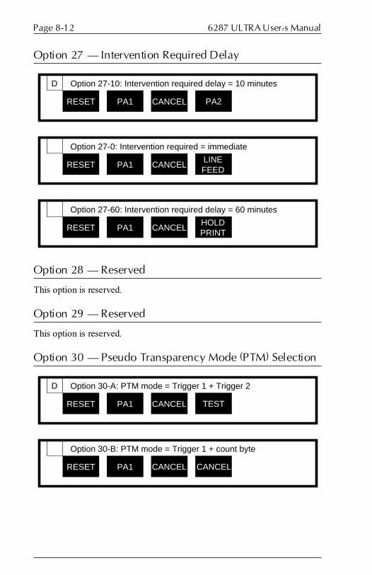
6287 ULTRA User�s ManualPage 8-12
Option 27 � Intervention Required Delay
Option 27-10: Intervention required delay = 10 minutes
RESET PA1
Option 27-0: Intervention required = immediate
RESET PA1
PA2
D
CANCEL
CANCELLINE FEED
Option 27-60: Intervention required delay = 60 minutes
RESET PA1 CANCELHOLD PRINT
Option 28 � Reserved
This option is reserved.
Option 29 � Reserved
This option is reserved.
Option 30 � Pseudo Transparency Mode (PTM) Selection
Option 30-A: PTM mode = Trigger 1 + Trigger 2
RESET PA1
Option 30-B: PTM mode = Trigger 1 + count byte
RESET PA1
TEST
D
CANCEL
CANCEL CANCEL

Page 8-13FRONT PANEL CONFIGURATION
Option 31 � Discard PTM Terminating Delimiter
Option 31-N: Discard PTM terminating delimiter = NO
RESET PA1
Option 31-Y: Discard PTM terminating delimiter = YES
RESET PA1
FORM FEED
D
CANCEL
CANCELENABLE PRINT
Option 32 � DSC Trigger 1
This option can be changed only from either the coax host or an alternatehost. Refer to Section 9 � Coax Host Configuration and Section 10 �Alternate Host Configuration for instructions.
Option 33 � DSC Trigger 2
This option can be changed only from either the coax host or an alternatehost. Refer to Section 9 � Coax Host Configuration and Section 10 �Alternate Host Configuration for instructions.
Option 34 � SCS Trigger 1
This option can be changed only from either the coax host or an alternatehost. Refer to Section 9 � Coax Host Configuration and Section 10 �Alternate Host Configuration for instructions.
Option 35 � SCS Trigger 2
This option can be changed only from either the coax host or an alternatehost. Refer to Section 9 � Coax Host Configuration and Section 10 �Alternate Host Configuration for instructions.
Option 36 � Reserved
This option is reserved.
Option 37 � Reserved
This option is reserved.

6287 ULTRA User�s ManualPage 8-14
Option 38 � Reserved
This option is reserved.
Option 39 � Non-Transparency Trigger 1 Output
This option can be changed only from either the coax host or an alternatehost. Refer to Section 9 � Coax Host Configuration and Section 10 �Alternate Host Configuration for instructions.
Option 40 � Alternate Host Lockout Duration
Option 40-3: Alternate host lockout duration = 3 seconds
RESET PA1
Option 40-10: Alternate host lockout duration = 10 seconds
RESET PA1
PA1
D
FORM FEED
PA2
Option 40-255: Alternate host lockout duration = 255 seconds
RESET PA1LINE FEED
FORM FEED
FORM FEED
Option 41 � Serial Alternate Host CTS Enabled
Option 41-Y: Serial alternate host CTS handshaking = YES
RESET PA1
Option 41-N: Serial alternate host CTS handshaking = NO
RESET PA1
HOLD PRINT
D
FORM FEED
TESTFORM FEED

Page 8-15FRONT PANEL CONFIGURATION
Option 42 � Reserved
This option is reserved.
Option 43 � Reserved
This option is reserved.
Option 44 � Reserved
This option is reserved.
Option 45 � Reserved
This option is reserved.
Option 46 � Reserved
This option is reserved.
Option 47 � Reserved
This option is reserved.
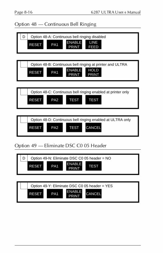
6287 ULTRA User�s ManualPage 8-16
Option 48 � Continuous Bell Ringing
Option 48-A: Continuous bell ringing disabled
RESET PA1
Option 48-B: Continuous bell ringing at printer and ULTRA
RESET PA1
LINE FEED
D
ENABLE PRINT
ENABLE PRINT
HOLD PRINT
Option 48-C: Continuous bell ringing enabled at printer only
RESET PA2
Option 48-D: Continuous bell ringing enabled at ULTRA only
RESET PA2
TEST
TEST
TEST
CANCEL
Option 49 � Eliminate DSC C0 05 Header
Option 49-N: Eliminate DSC C0 05 header = NO
RESET PA1
Option 49-Y: Eliminate DSC C0 05 header = YES
RESET PA1
TEST
D
ENABLE PRINT
ENABLE PRINT
CANCEL

Page 8-17FRONT PANEL CONFIGURATION
Option 50 � Alternate Host Enable/Disable
D Option 50-A: Alternate host disabled
RESET PA2 TEST PA1
Option 50-B: Alternate host enabled = both serial & parallel
RESET PA2 TEST PA2
Option 50-C: Alternate host enabled = serial only
RESET PA2 TESTLINE FEED
Option 50-D: Alternate host enabled = parallel only
RESET PA2 TESTHOLD PRINT
Option 51 � DSC EM CR/LF in Infinite Line Length
Option 51-N: DSC EM CR/LF in infinite line length = NO
RESET PA2
Option 51-Y: DSC EM CR/LF in infinite line length = YES
RESET PA2
PA2
D
PA1
PA1LINE FEED

6287 ULTRA User�s ManualPage 8-18
Option 52 � SCS EM Always Generates CR/LF
Option 52-Y: SCS EM generates CR/LF in column 1 = YES
RESET PA2
Option 52-N: SCS EM generates CR/LF in column 1 = NO
RESET PA2
HOLD PRINT
D
PA1
PA1 TEST
Option 53 � IBM 35 Hex Transparency
Option 53-Y: IBM 35 hex transparency =YES
RESET PA2
Option 53-N: IBM 35 hex transparency = NO
RESET PA2
CANCEL
D
PA1
PA1FORM FEED
Option 54 � Power On Reset After 60 Seconds
Option 54-N: POR after 60 seconds = NO
RESET PA2
Option 54-Y: POR after 60 seconds = YES
RESET PA2
ENABLE PRINT
D
PA1
PA2 PA1

Page 8-19FRONT PANEL CONFIGURATION
Option 55 � MD-Laser Support
Option 55-N: MD-Laser support = NO
RESET PA2
Option 55-Y: MD-Laser support = YES
RESET PA2
PA2
D
PA2
PA2LINE FEED
Option 56 � Reserved
This option is reserved.
Option 57 � DSC NL at EM Even if in Column 1
Option 57-N: DSC NL at EM even if in column 1 = NO
RESET PA2
Option 57-Y: DSC NL at EM even if in column 1 = YES
RESET PA2
CANCEL
D
PA2
PA2FORM FEED
Option 58 � Xerox Metacode Support
D Option 58-N: Xerox Metacode support = NO
RESET PA2 LINE FEED
PA1
Option 58-Y: Xerox Metacode support = YES
RESET PA2 PA2LINE FEED

6287 ULTRA User�s ManualPage 8-20
Option 59 � AGILE Laserpage Support
D Option 59-N: AGILE Laserpage support = NO
RESET PA2LINE FEED
Option 59-Y: AGILE Laserpage support = YES
RESET PA2HOLD PRINT
LINE FEED
LINE FEED
Option 60 � Xerox Graphic Window Support
D Option 60-N: Xerox Graphic Window support = NO
RESET PA2LINE FEED
TEST
Option 60-Y: Xerox Graphic Window support = YES
RESET PA2 CANCELLINE FEED
Option 61 � Reserved
This option is reserved.
Option 62 � Allow EBCDIC Font Downloading
D Option 62-N: Allow EBCDIC font downloading = NO
RESET PA2HOLD PRINT
PA1
Option 62-Y: Allow EBCDIC font downloading = YES
RESET PA2 PA2HOLD PRINT

COAX HOST CONFIGURATION
General Information
This section describes how to configure the ULTRA using a host-connectedterminal. A local copy sent to the ULTRA while in coax host configurationmode will alter the configuration selections listed in Section 5 �Configuration Options. Changes can also be made to the PFSs described inSection 6 � Programmable Function Strings and to the translate tablesdescribed in Section 7 � Translate Tables.
Before any configuration changes can be made through the controller coaxport, dip switch B7 must be set in the ON (down) position, and then theRESET button on the ULTRA front panel must be pressed.
After all configuration changes have been made, set dip switch B7 in theOFF (up) position and press the RESET button on the ULTRA front panel.Check that the configuration is correct by pressing the TEST button on theULTRA front panel to print out a General Configuration Report.
All configuration option sequences take the following format:
Trigger 1 (the cent sign ¢ is the default) - question mark (?) - option # -equals sign (=) - valid option parameter selection - terminator (;). No spacesare allowed in the command sequence.
For example, if Trigger 1 is the default cent sign (¢), the followingsequence will set the number of lines per page (Option #2) to 51:
¢?2=51;
The cent sign (¢) is Trigger 1; the question mark (?) indicates that thefollowing character sequence is a configuration option command; thenumeral two (2) indicates that the configuration option to be defined isOption #2; the equals sign (=) is used to separate the option number fromthe valid option parameter value; the numeral fifty-one (51) is the value ofthe option parameter; and the semicolon (;) is the terminator.
Valid option parameters will be one of the following, depending upon theoption:
� A decimal numeric value� A two-character hexadecimal value� The letter value of an option parameter (A- E)� A �Y� for YES or an �N� for NO
SECTION 9

6287 ULTRA User�s ManualPage 9-2
After the user�s selections are keyed on the screen, press the local copy keyon the terminal. The ULTRA will interpret each command and store thenew selections in its non-volatile, battery-backed RAM. This is a form ofpermanent storage that will hold the selections even when the unit ispowered off.
The command sequences will not be printed. They will affect only theconfiguration of the ULTRA.
Multiple Option Selections
The user can change the parameters of more than one option in a singleline. Only one terminator per line is necessary to download option values.To download several option parameters on a single line, the user mustseparate each sequence with a comma (,) after each valid option parametervalue.
The following example illustrates multiple command selection, whereTrigger 1 is the default cent sign (¢). It sets the column width (Option #1) to80, turns off local copy null line suppression (Option #4) and sets output(Option #10) to EBCDIC mode:
¢?1=80,4=N,10=B;
Multiple lines may be used to download configuration option parameters.Each line must have its own trigger and its own terminator.
Resetting All Options to Factory Defaults
To reset all options to factory preset default values, send the followingcommand to the ULTRA:
¢?0;
where the cent sign (¢) is Trigger 1 (the default).
Note: This command will reset all General Configuration options, allprogrammable function strings and all translate tables to their factorypresets. All modifications to any parameters will be lost.

Page 9-3COAX HOST CONFIGURATION
Coax Host Configuration Within Data Streams
Configuration options may also be changed within a coax data streamwithout changing any dip switch settings (i.e., without setting dip switch B7in the ON position) and without pressing the RESET button on the ULTRAfront panel. This is useful for embedding configuration changes within adata stream.
To change the ULTRA configuration in this manner, bracket the normalconfiguration string with Trigger 1 - question mark - Trigger 1 (¢?¢ bydefault). For example, if Trigger 1 is the default cent sign (¢), to changeOption #1 to 0 (infinite line length), the command would be:
¢?¢¢?1=0;¢?¢
In effect, the ¢?¢ command logically replaces the physical act of changingdip switch B7. The second ¢?¢ command logically replaces the physical actof pressing the RESET button after all configuration changes have beenmade.
Note: If the user intends to embed configuration commands within the datastreams of print jobs, Option #1 � Column Width should be set to 0(infinite line length), Option #2 � Lines Per Page should be set to 0(infinite page length), and Option #15 � Bold Print Emulation should beset to C (none). Otherwise, unpredictable formatting errors could occur.Refer to Section 13 � DisplayWrite 370 Support for more information.
Download Error Messages
Errors in command sequences will result in the ULTRA sending adownload error message to the printer.
An invalid option number will result in the following message:
DOWNLOAD ERROR - BAD OPTION FIELD VALUE
If this message is printed, no change will take effect. The user must resendthe command sequence with a valid option number. If the user was sendingmultiple command sequences to the ULTRA, all valid option numbers willbe changed, but the invalid option numbers will remain unchanged. AGeneral Configuration Report must be printed to determine which of theoptions in the command sequences were valid and which were incorrect.

6287 ULTRA User�s ManualPage 9-4
An invalid option parameter (a value outside the valid range for the option)will result in the following message. The example shown indicates that theparameter value for Option #45 was not in the valid range for that option:
DOWNLOAD ERROR - BAD DATA FIELD VALUE45=XX THROWN AWAY
In the event that this message is printed, the user must resend the commandsequence for Option #45 with a parameter value in the valid range for thatoption.
An invalid separator message indicates that the option number and theparameter value were not separated by an equals sign (=):
DOWNLOAD ERROR - BAD FIELD SEPARATOR
Downloading Programmable Function Strings
PFS downloading commands take the following format:
Trigger 1 (the cent sign ¢ is the default) - percent sign (%) - PFS # -hexadecimal data pair(s) - percent sign (%). Note that the percent sign bothinitiates and terminates the downloading sequence. No spaces are allowed.
For example, if Trigger 1 is the default cent sign (¢), the followingsequence will define the PFS 0 � Power On Sequence as the hexadecimalpairs 31h and 32h:
¢%03132%
The cent sign (¢) is Trigger 1; the first percent sign (%) indicates that thefollowing character sequence is a PFS configuration command; the numeralzero (0) indicates that the PFS to be defined is PFS 0; the numerals 31 and32 are the hexadecimal pairs that will be sent to the printer when this PFS isinvoked; and the second percent sign (%) is the terminator.
To replace the definition of a PFS, download a new definition. To delete aPFS, replace the definition with a space (the ASCII space character is 20h).For example, the following sequence deletes the contents of PFS 0:
¢%020%
PFSs are restricted to a maximum of 76 characters. The custom banner(PFS D) is entered as text, rather than as pairs of hexadecimal characters.

Page 9-5COAX HOST CONFIGURATION
Note: If the user intends to download PFS definitions within the datastreams of print jobs, Option #1 � Column Width should be set to 0(infinite line length), Option #2 � Lines Per Page should be set to 0(infinite page length), and Option #15 � Bold Print Emulation should beset to C (none). Otherwise, unpredictable formatting errors could occur.Refer to Section 12 � DisplayWrite 370 Support for more information.
Multiple Function Strings
Programmable Function Strings may be set up so they will automaticallyexecute additional PFSs. By including a plus sign (+) as the last character ina PFS, the ULTRA will send that PFS plus the following PFS to the printer.For example, if PFS 3 is defined as:
[xx][xx][xx]+ (where [xx] represents a hexadecimal pair)
whenever PFS 3 is executed, the contents of both PFS 3 and PFS 4 will besent to the printer.
By including a plus sign (+) and a PFS number as the last two characters ina PFS, the ULTRA will send that PFS plus PFS n to the printer. Forexample, if PFS 2 is defined as:
[xx][xx][xx]+7 (where [xx] represents a hexadecimal pair)
whenever PFS 2 is executed, the contents of both PFS 2 and PFS 7 will besent to the printer.
Downloading Translate Tables
All spaces, nulls and carriage control characters (CR, NL, LF, FF) will beignored during translate table downloading. This allows the user to separateentries for easier reading, and it prevents the data from becoming corruptedby host forms control.
Note: If the user intends to download translate tables within the datastreams of print jobs, Option #1 � Column Width should be set to 0(infinite line length), Option #2 � Lines Per Page should be set to 0(infinite page length), and Option #15 � Bold Print Emulation should beset to C (none). Otherwise, unpredictable formatting errors could occur.Refer to Section 12 � DisplayWrite 370 Support for more information.
Downloading an Entire Translate Table
Downloading an entire translate table will use the following format:

6287 ULTRA User�s ManualPage 9-6
Trigger 1 (the cent sign ¢ is the default) - exclamation point (!) - translatetable # - all 256 hexadecimal data pairs in the table, in order. The followingexample illustrates downloading the contents of Translate Table 1, whereTrigger 1 is the default cent sign (¢) and where xx...xx represents the 256values of a translate table:
¢!1xx...xx
Downloading a Single Translate Table Value
Downloading a change to a single translate table position value will use thefollowing format:
Trigger 1 (the cent sign ¢ is the default) - exclamation point (!) - translatetable # - hexadecimal position # - hexadecimal value - semicolon (;). Thefollowing example illustrates changing the value of Translate Table 1,position 16 to a value of 99h, where Trigger 1 is the default cent sign (¢):
¢!11699;
Downloading a Partial Translate Table
Downloading a partial change to a translate table will use the followingformat:
Trigger 1 (the cent sign ¢ is the default) - exclamation point (!) - translatetable # - hexadecimal offset position # - hexadecimal values - semicolon (;).Commas (,) must be used to separate each hexadecimal value to bedownloaded. The following example illustrates changing the value of alllowercase letters in Translate Table 1 to uppercase letters, where Trigger 1is the default cent sign (¢):
¢!18041,42,43,44,45,46,47,48,49,4A,4B,4C,4D,4E,4F,50,51,52,53,54,55,56,57,58,59,5A;
The offset position number indicates the location in the table where thechanges to the translate table will begin (location 80 was used in theexample above). Any values in the character string after the offset positionvalue will replace subsequent values in consecutive order in the table.Downloading will end when a semicolon (;) is received.

ALTERNATE HOST CONFIGURATION
General Information
This section describes how to configure the ULTRA from an alternate host.Sending (printing) a file containing configuration command sequenceswhile in alternate host configuration mode will alter the configurationselections listed in Section 5 � Configuration Options. Changes can also bemade to the PFSs described in Section 6 � Programmable Function Stringsand to the translate tables described in Section 7 � Translate Tables.
Before any configuration changes can be made through the alternate hostport, the ULTRA alternate host port must be configured using Option #50.Refer to Section 8 � Front Panel Configuration or Section 9 � Coax HostConfiguration for instructions. Users with an alternate host connected viaserial interfacing must also set dip switches B1 and B2 to match the parityof the serial interface and dip switches B3, B4 and B5 to match the baudrate of the serial interface.
To make configuration changes through the alternate host port, set dipswitches B7 and B8 in the ON (down) position, then press the RESETbutton on the ULTRA front panel. The POWER and DATA OUT StatusIndicator Lights will be the only ones on during alternate host configurationmode.
After all configuration changes have been made, set dip switches B7 and B8in the OFF (up) position and press the RESET button on the ULTRA frontpanel. The Status Indicator Lights will confirm that the unit is in normaloperating mode. Check that the configuration is correct by pressing theTEST button on the ULTRA front panel to print out a GeneralConfiguration Report.
Alternate Host Configuration Rules
1. Each option must be on its own line in the file.2. Use UPPERCASE ASCII data only.3. No comments are allowed in the file.4. No spaces are allowed.5. A carriage control character (CR, LF, FF, SP) must follow the last
configuration setting in the file.
SECTION 10

6287 ULTRA User�s ManualPage 10-2
All configuration option sequences take the following format on one line inthe file:
Option # - equals sign (=) - valid option parameter selection. For example:
To set infinite line length (Option #1), put this line in the file:
1=0
To select EBCDIC output (Option #10):
10=B
To disable Intervention Required (Option #26):
26=N
Valid option parameters will be one of the following, depending upon theoption:
� A decimal numeric value (0-255)� A two-character hexadecimal value (00-FF)� The letter value of an option parameter (A- E)� A �Y� for YES or an �N� for NO (Y or N)
After the user�s selections are keyed on the screen, press the Print Screenkey (or device equivalent) on the alternate host. The ULTRA will interpreteach command and store the new selections in its non-volatile, battery-backed RAM. This is a form of permanent storage that will hold theselections even when the unit is powered off.
The command sequences will not be printed. They will affect only theconfiguration of the ULTRA.
The user is advised to exercise care when entering configuration changesfrom an alternate host. No error messages will be displayed if an entry isinvalid.
Resetting All Options to Factory Defaults
To reset all options to factory preset default values, send the followingcommand (a dollar sign) to the ULTRA, or the user may send a zero (0)follwed by a semicolon (;):
$ or 0;
Note: This command will reset all General Configuration options, allprogrammable function strings and all translate tables to their factorypresets. All modifications to any parameters will be lost.
Page 10-3ALTERNATE HOST CONFIGURATION
Downloading Programmable Function Strings
PFS downloading commands take the following format:
Percent sign (%) - PFS # - hexadecimal data pair(s). No spaces are allowedin the command sequence.
For example, the following sequence will define the PFS 0 � Power OnSequence as the hexadecimal pairs 31h and 32h:
%03132
The percent sign (%) indicates that the following character sequence is aPFS configuration command; the numeral zero (0) indicates that the PFS tobe defined is PFS 0; and the numerals 31 and 32 are the hexadecimal pairsthat will be sent to the printer when this PFS is invoked.
To replace the definition of a PFS, download a new definition. To delete aPFS, send the PFS command sequence without including a hexadecimalpair. The following sequence deletes the contents of PFS 1 � 6 LPI:
%1
Note: PFSs are restricted to a maximum of 76 characters. The custombanner (PFS D) is entered as text, rather than as pairs of hexadecimalcharacters.
Multiple Function Strings
Programmable Function Strings may be set up so they will automaticallyexecute additional PFSs. By including a plus sign (+) as the last character ina PFS, the ULTRA will send that PFS plus the following PFS to the printer.For example, if PFS 3 is defined as:
[xx][xx][xx]+ (where [xx] represents a hexadecimal pair)
whenever PFS 3 is executed, the contents of both PFS 3 and PFS 4 will besent to the printer.
By including a plus sign (+) and a PFS number as the last two characters ina PFS, the ULTRA will send that PFS plus PFS n to the printer. Forexample, if PFS 2 is defined as:
[xx][xx][xx]+7 (where [xx] represents a hexadecimal pair)
whenever PFS 2 is executed, the contents of both PFS 2 and PFS 7 will besent to the printer.

6287 ULTRA User�s ManualPage 10-4
Downloading Translate Tables
All spaces, nulls and carriage control characters (CR, NL, LF, FF) will beignored during translate table downloading. This allows the user to separateentries for easier reading, and it prevents the data from becoming corruptedby forms control from the alternate host application.
Downloading an Entire Translate Table
Downloading an entire translate table will use the following format:
Exclamation point (!) - translate table # - all 256 hexadecimal data pairs inthe table, in order. The following example illustrates downloading thecontents of Translate Table 1, where xx...xx represents the 256 values of atranslate table:
!1xx...xx
Downloading a Single Translate Table Value
Downloading a change to a single translate table position value will use thefollowing format:
Exclamation point (!) - translate table # - hexadecimal position # -hexadecimal value - semicolon (;). The following example illustrateschanging the value of Translate Table 1, position 16 to a value of 99h:
!11699;
Downloading a Partial Translate Table
Downloading a partial change to a translate table will use the followingformat:
Exclamation point (!) - translate table # - hexadecimal offset position # -hexadecimal values - semicolon (;). Commas (,) must be used to separateeach hexadecimal value to be downloaded. The following exampleillustrates changing the value of all lowercase letters in Translate Table 1 touppercase letters:
!18041,42,43,44,45,46,47,48,49,4A,4B,4C,4D,4E,4F,50,51,52,53,54,55,56,57,58,59,5A;
The offset position number indicates the location in the table where thechanges to the translate table will begin (location 80 was used in theexample above). Any values in the character string after the offset positionvalue will replace subsequent values in consecutive order in the table.Downloading will end when a semicolon (;) is received.

TRANSPARENCY MODES
General Information
Most ASCII and EBCDIC printers have features that are not available onIBM printers. If the user�s host application is aware that the destination ofthe data may be a non-IBM printer attached to a protocol converter, theapplication can take advantage of the printer�s advanced features. Toactivate a particular printer feature, the application will send a transparentcommand in the data stream. (Refer to the printer user�s manual for a list ofavailable printer commands.)
A transparent printer command, or transparency, consists of a trigger(character code) followed by the hexadecimal command that will activate aparticular printer feature. The trigger alerts the protocol converter that thedata that follows it is a printer command that should be sent directly to theprinter without translation.
If the appropriate form of transparency is activated, the ULTRA willrecognize the trigger and respond appropriately to that form oftransparency. The ULTRA can use standard IBM 35h, Xerox 36h andXerox Metacode transparency. The ULTRA provides its own version oftransparency, called pseudo transparency mode (PTM). It also is capable ofsupporting MD-Laser and AGILE Laserpage pseudo transparency.
Note: If the user or the user�s application embeds transparent or pseudotransparent strings in the data stream, Option #1 � Column Width shouldbe set to 0 (infinite line length), Option #2 � Lines Per Page should be setto 0 (infinite page length), and Option #15 � Bold Print Emulation shouldbe set to C (none). Otherwise, unpredictable formatting errors may occur.For more information, refer to Section 12 � DisplayWrite 370 Support.
IBM 35 Hex Transparency Mode
This form of transparency is valid only in SCS data streams. In IBM 35htransparency, the trigger character is 35h, and it indicates the start of thetransparent data stream. The 35h is followed by a count byte that indicatesthe length, in bytes, of the transparent data stream, not counting the countbyte itself. The count byte is followed by the actual data to be sent. Forinstance, the following code will send a Xerox 4045 printer reset command(Esc+X) using 35h transparency:
35031B2B58
SECTION 11

6287 ULTRA User�s ManualPage 11-2
This includes the trigger (35h), the count byte (03h), and the three bytes forEsc+X (1Bh, 2Bh, 58h).
The user can generate any possible eight-bit command or data byte that is tobe sent to the printer. There is a one-to-one correspondence between what isreceived by the ULTRA and what is sent to the printer.
IBM 35h is activated when Option #53 is set to �Yes�. If Option #53 is setto �No, then the trigger, the count byte and all of the otherwise transparentcharacters will be printed normally, as indicated by the active translate table(see Section 7 � Translate Tables). Refer to Section 14 � SCS DataStreams for more information on IBM 35h transparency.
Metacode Transparency Mode
Metacode is a variation of 35h transparency, with the exception that thistransparency mode is handled directly by the printer, rather than by theULTRA. Metacode is used by some Xerox printers (the Xerox 4235, forexample).
The data seen by the ULTRA and the printer are identical when this type ofdata is detected. If Option #58 is set to �Yes,� the ULTRA will send the 35hand the count byte directly to the printer without any translation, rather thanremoving them from the data stream. It also sends the remaining bytes inthe transparent packet without any translation.
For example, the character string 35h, 02h, 41h, 41h would be output to theprinter in 35h transparency as two characters: 4141. In Metacodetransparency, all four characters would be sent to the printer: 35024141.
If Option #58 is set to �No,� then the trigger, the count byte and all of theotherwise transparent characters will be printed normally, as indicated bythe active translate table (see Section 7 � Translate Tables).
Xerox 36 Hex Transparency Mode
This form of transparency is identical to 35h transparency, except that thetrigger character is 36h. Xerox applications typically use 36h instead of 35hto send data directly to the printer.
If Option #5 is set to �Yes,� the ULTRA detects the trigger, picks up thecount byte and starts �passing through� the remaining data. If Option #5 isset to �No,� then the trigger, the count byte and all of the otherwisetransparent data will be printed normally, as indicated by the activetranslate table (see Section 7 � Translate Tables).
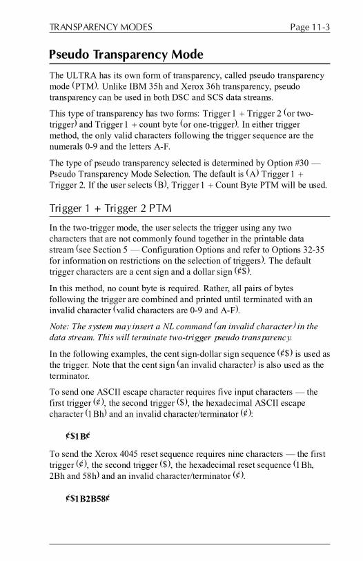
Page 11-3TRANSPARENCY MODES
Pseudo Transparency Mode
The ULTRA has its own form of transparency, called pseudo transparencymode (PTM). Unlike IBM 35h and Xerox 36h transparency, pseudotransparency can be used in both DSC and SCS data streams.
This type of transparency has two forms: Trigger 1 + Trigger 2 (or two-trigger) and Trigger 1 + count byte (or one-trigger). In either triggermethod, the only valid characters following the trigger sequence are thenumerals 0-9 and the letters A-F.
The type of pseudo transparency selected is determined by Option #30 �Pseudo Transparency Mode Selection. The default is (A) Trigger 1 +Trigger 2. If the user selects (B), Trigger 1 + Count Byte PTM will be used.
Trigger 1 + Trigger 2 PTM
In the two-trigger mode, the user selects the trigger using any twocharacters that are not commonly found together in the printable datastream (see Section 5 � Configuration Options and refer to Options 32-35for information on restrictions on the selection of triggers). The defaulttrigger characters are a cent sign and a dollar sign (¢$).
In this method, no count byte is required. Rather, all pairs of bytesfollowing the trigger are combined and printed until terminated with aninvalid character (valid characters are 0-9 and A-F).
Note: The system may insert a NL command (an invalid character) in thedata stream. This will terminate two-trigger pseudo transparency.
In the following examples, the cent sign-dollar sign sequence (¢$) is used asthe trigger. Note that the cent sign (an invalid character) is also used as theterminator.
To send one ASCII escape character requires five input characters � thefirst trigger (¢), the second trigger ($), the hexadecimal ASCII escapecharacter (1Bh) and an invalid character/terminator (¢):
¢$1B¢
To send the Xerox 4045 reset sequence requires nine characters � the firsttrigger (¢), the second trigger ($), the hexadecimal reset sequence (1Bh,2Bh and 58h) and an invalid character/terminator (¢).
¢$1B2B58¢

6287 ULTRA User�s ManualPage 11-4
Trigger 1 + Count Byte PTM
In the one-trigger mode, the user selects the trigger using any singlecharacter that is not commonly found in the printable data stream (seeSection 5 � Configuration Options and refer to Options 32 and 34 forinformation on restrictions on the selection of triggers). The default triggeris a cent sign (¢).
The one-trigger mode requires a count byte following the trigger that tellsthe ULTRA how many pairs of additional characters will follow the countbyte (the count byte is not included in the count).
To send 1 ASCII escape character requires five input characters � thetrigger (¢), the hexadecimal count byte (01h) and the hexadecimal ASCIIescape character (1Bh):
¢011B
To send the Xerox 4045 reset sequence requires nine characters � thetrigger (¢), the hexadecimal count byte (03h) and the hexadecimal resetsequence (1Bh, 2Bh and 58h):
¢031B2B58
MD-Laser Pseudo Transparency
The ULTRA is capable of supporting �continuous escape,� a form ofpseudo transparency offered in Maersk Data products. It is triggered bySCS Trigger 1 (see Option #34) followed by C2h. If Option #55 is set to�Yes,� when this sequence is detected in the data stream, the ULTRA willpass the subsequent hexadecimal pairs of data to the printer withouttranslation until terminated when SCS Trigger 1 is encountered again.Spaces and control codes in between the Trigger 1 characters are ignored.
When in use, the ULTRA begins checking for valid pairs of hexadecimalcharacters. When the ULTRA detects an asterisk, it combines the two bytesprior to the asterisk to form a count byte, and it combines the two bytesafter the asterisk to form a repeat byte. The ULTRA then sends out therepeat byte to the printer the number of times indicated by the count byte.This provides some compression of graphic data.
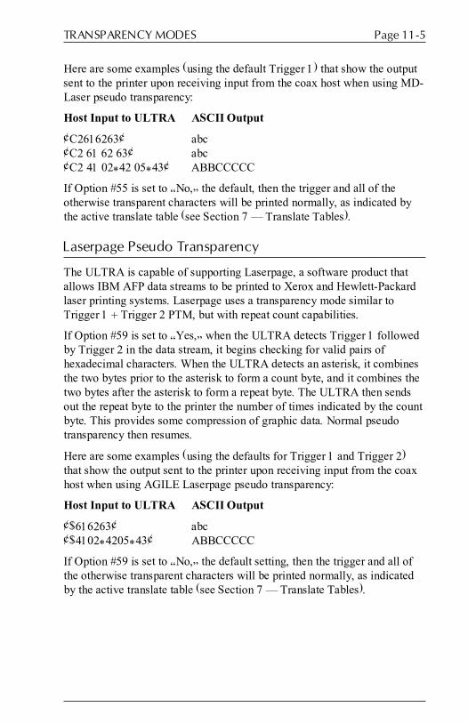
Page 11-5TRANSPARENCY MODES
Here are some examples (using the default Trigger 1) that show the outputsent to the printer upon receiving input from the coax host when using MD-Laser pseudo transparency:
Host Input to ULTRA ASCII Output
¢C2616263¢ abc¢C2 61 62 63¢ abc¢C2 41 02*42 05*43¢ ABBCCCCC
If Option #55 is set to �No,� the default, then the trigger and all of theotherwise transparent characters will be printed normally, as indicated bythe active translate table (see Section 7 � Translate Tables).
Laserpage Pseudo Transparency
The ULTRA is capable of supporting Laserpage, a software product thatallows IBM AFP data streams to be printed to Xerox and Hewlett-Packardlaser printing systems. Laserpage uses a transparency mode similar toTrigger 1 + Trigger 2 PTM, but with repeat count capabilities.
If Option #59 is set to �Yes,� when the ULTRA detects Trigger 1 followedby Trigger 2 in the data stream, it begins checking for valid pairs ofhexadecimal characters. When the ULTRA detects an asterisk, it combinesthe two bytes prior to the asterisk to form a count byte, and it combines thetwo bytes after the asterisk to form a repeat byte. The ULTRA then sendsout the repeat byte to the printer the number of times indicated by the countbyte. This provides some compression of graphic data. Normal pseudotransparency then resumes.
Here are some examples (using the defaults for Trigger 1 and Trigger 2)that show the output sent to the printer upon receiving input from the coaxhost when using AGILE Laserpage pseudo transparency:
Host Input to ULTRA ASCII Output
¢$616263¢ abc¢$4102*4205*43¢ ABBCCCCC
If Option #59 is set to �No,� the default setting, then the trigger and all ofthe otherwise transparent characters will be printed normally, as indicatedby the active translate table (see Section 7 � Translate Tables).

6287 ULTRA User�s ManualPage 11-6
Other Pseudo Transparency Mode Considerations
Some applications insert unnecessary spaces before pseudo transparencytrigger character(s). Option #13 � Suppress Spaces Before PTM Packetswill tell the ULTRA to delete any spaces or null characters in between aPTM trigger and the text that precedes the trigger. To delete unnecessaryspace characters, set Option #13 to �Yes.� The default setting is �No.�
In Trigger 1 + Trigger 2 pseudo transparency mode, PTM is terminatedwith any character outside the valid range of values (the valid range is 0-9and A-F). Option #31 � Discard PTM Terminating Delimiter gives usersthe option of either printing or discarding the terminating character. Todiscard the terminator, set Option #31 to �Yes.� To print the terminator, use�No,� the default value.
Option #39 � Non-Transparency Trigger 1 Output determines thecharacter that will be output to the printer when Option #30 � PseudoTransparency Mode Selection is set to (A) Trigger 1 + Trigger 2 and whenTrigger 1 is encountered in the data stream followed by a character otherthan Trigger 2. The default output character is 9Bh, which has no affect onprinted output, but the user may set the value to any two-characterhexadecimal value.

DISPLAYWRITE 370 SUPPORT
General Information
DisplayWrite 370 is a word processing application that provides thecapability to bold, underline or overstrike text. DisplayWrite 370 printingfeatures are supported by the ULTRA when Option #15 is set either to (A)3287 printer emulation or (B) DisplayWrite 370 emulation.
To access these features, the user should read and understand Section 6 �Programmable Function Strings. The PFSs that are utilized by theDisplayWrite printing features are:
3 DisplayWrite 370 Overstriking On
4 DisplayWrite 370 Overstriking Off
5 DisplayWrite 370 Underlining On
6 DisplayWrite 370 Underlining Off
9 DisplayWrite 370 Bolding On
A DisplayWrite 370 Bolding Off
Each of these PFSs must be defined by the user for the target printer beforethe respective DisplayWrite feature is implemented. Refer to the printeruser�s manual for the appropriate control sequences for each of thesefunctions. For instructions on programming PFSs, refer to Section 9 �Coax Host Configuration or Section 10 � Alternate Host Configuration.
Document Formatting Information
With DisplayWrite 370 enabled (when Option #15 � Bold Print Emulationis set either to (A) 3287 printer emulation or (B) DisplayWrite 370emulation), the data stream is handled in quite a different way than whenDisplayWrite is disabled.
SECTION 12
6287 ULTRA User�s ManualPage 12-2
When DisplayWrite is OFF, the data stream is sent to the printer a characterat a time as it is received. In this mode, it is permissible for the user toembed printer-specific escape sequences or PFS commands in the datastream with predictable results. However, users with laser printers will beunable to achieve bolding of text unless they invoke a bold font.
When DisplayWrite is ON, each line of text is buffered until a new line(CR/LF) is received, or until the column limit (determined by Option #1 �Column Width) is reached, whichever comes first. No escape sequencesshould be added to the data stream by the user when DisplayWrite is ON,because these escape sequences will be added to the column count, andbecause they will come into conflict with the escape sequences being sentto the printer by the ULTRA. In other words, the user cannot expect to beable to control the printer with escape sequences at the same time that theULTRA is trying to control the printer, because conflicts will inevitablyoccur with unpredictable results.
Similarly, the user should avoid embedding PFS commands in the datastream when DisplayWrite is ON. While these commands are not added tothe column count, they can cause formatting problems because they are notbuffered along with the text. Rather, they are sent to the printer immediatelyupon receipt by the ULTRA. Thus, any PFS command will affect the entireline of text, not just the text that follows the command. For instance, ifPFS 9 � DisplayWrite 370 Bolding On and PFS A � DisplayWrite 370Bolding Off are on the same line of text, no text in the line will be bolded,because the printer will receive bold on and bold off commands before anytext is sent to the printer.
Note: To avoid unexpected formatting results, Option #1 � Column Widthshould be set to infinite line length, Option #2 � Lines Per Page should beset to infinite page length, and Option #15 � Bold Print Emulation shouldbe set to C (none) if any of the following are true:
� the user or the user�s application embeds escape sequences in thedata stream
� the user or the user�s application embeds transparency or pseudotransparency strings in the data stream
� the user embeds ULTRA commands (configuration, translate table orPFS commands) within print jobs.
If DisplayWrite is ON (Option 15-A or 15-B), Option #1 � Column Widthshould be set to a non-zero value. The ULTRA will not buffer more than 255characters per line.
Page 12-3DISPLAYWRITE 370 SUPPORT
Overstriking
If Option #15 is set to (A) or (B), the ULTRA will enter overstrike mode(i.e., send PFS 3 to the printer) when a [character-backspace-differentcharacter] sequence is detected in the data stream. The ULTRA will exitoverstrike mode (i.e., send PFS 4 to the printer) whenever a [character-character] sequence is detected in the data stream while in overstrike mode.
Underlining
If Option #15 is set to (A) or (B), the ULTRA will enter underline mode(i.e., send PFS 5 to the printer) when a [character-backspace-underscore]sequence is detected in the data stream. The ULTRA will exit underlinemode (i.e., send PFS 6 to the printer) whenever a [character-character]sequence is detected in the data stream while in underline mode.
Bolding
If Option #15 is set to (A) or (B), the ULTRA will enter bold mode (i.e.,send PFS 9 to the printer) when a [character-backspace-same character]sequence is detected in the data stream. The ULTRA will exit bold mode(i.e., send PFS A to the printer) whenever a [character-character] sequenceis detected in the data stream while in bold mode.


COAX HOST CONSIDERATIONS
The ULTRA can process data from a variety of IBM host systems. Thissection discusses how to ensure compatibility between the ULTRA and thehost system.
System Configuration
The coax host software generation requirements of the 6287 ULTRA aregenerally the same as the requirements for an IBM 3287 or 3289 printerwith SCS support. Except where stated otherwise, the coax host softwaresystem requirements are the same as for an IBM 3174, 3274 or 3276 controlunit with 3287 or 3289 printers attached.
To function properly, the ULTRA/printer combination must be defined tothe coax host system as a 3287 printer with a 4K maximum physical bufferand/or with whatever other features are required by the application and aresupported by the ULTRA. The ULTRA does not support 3287-type optionssuch as Program Symbols.
The ULTRA is classified as a �Category A� device, and it can be attachedto IBM 4300 systems with integral Display Printer Adapters (DPA) and toIBM 3174, 3274 and 3276 control units configured with Type A deviceadapters. The ULTRA does not emulate a Category B device, and it will notwork if attached to a Type B device adapter.
(Devices such as CRTs and printers that connect to IBM 3270 control unitsare classified as either Category A or Category B devices. All new controlunits are configured with Type A device adapters. The Category B devicesare those that are supported by IBM 3271 and 3272 control units configuredwith Type B device adapters. 3274 control units can also be configuredwith Type B device adapters for support of Category B devices.)
Category A Devices Category B Devices3262 Line Printer 3277 Display Station3278 Display Station 3284 Character Printer3279 Color Display Station 3286 Character Printer3287 Character Printer 3288 Line Printer3289 Line Printer
SECTION 13

6287 ULTRA User�s ManualPage 13-2
VTAM and Network Control ProgramRequirements
The 3174, 3274 or 3276 control unit to which the ULTRA is attached mustbe defined as a type 2 physical unit and the logical unit (type 1 or 3)definition must be included for each ULTRA to be attached. The followingis an example of log mode entry tables for DSC and SCS that may be usedwith the ULTRA. If necessary, consult with the Company System Managerregarding specific requirements for the system, environment andapplications.
DSC2K MODEENTLOGMODE=DSC2KBIND USED FOR APPLICATION SESSIONS
FMPROF=X�03' FUNCTION MANAGEMENT PROFILETSPROF=X�03' TRANSMISSION SERVICES PROFILEPRIPROT=X�B1' PRIMARY PROTOCOLSECPROT=X�90' SECONDARY PROTOCOLCOMPROT=X�3080' COMMON PROTOCOLRUSIZES=X�8787' PRI RUSIZE=1024, SEC RUSIZE=1024PSERVIC=X�030000000000185018507F00'
LU SERVICES PROFILE
SCS MODEENT LOGMODE=SCSBIND USED FOR APPLICATION SESSIONS
FMPROF=X�03' FUNCTION MANAGEMENT PROFILETSPROF=X�03' TRANSMISSION SERVICES PROFILEPRIPROT=X�B1' PRIMARY PROTOCOLSECPROT=X�90' SECONDARY PROTOCOLCOMPROT=X�3080' COMMON PROTOCOLRUSIZES=X�87C6' PRI RUSIZE-768, SEC RUSIZE=1024PSNDPAC=X�01' PRIMARY SEND PACING COUNTSRCVPAC=X�01' SECONDARY RECEIVE PACING COUNTPSERVIC=X�01000000E100000000000000'
LU SERVICES PROFILE
APL Support
APL is supported only for DSC data streams when the ULTRA isoutputting data using the ASCII character set. When using APL, the DSClog mode entry table above will be the same except for the last line,�PSERVIC=X'� .� A change must be made to the byte following the�X'03.� The second byte (00) must be changed to another value, dependingupon the device for which the user�s application was written. The followingtable indicates the appropriate replacement value.

Page 13-3COAX HOST CONSIDERATIONS
00 = For applications written for a device with old APL and withoutExtended Data Stream capability.
20 = For applications written for a VSCS printer (VM only).
40 = For applications written for a device with new APL.
80 = For applications written for a device with Extended Data Streamcapability.
C0 = For applications written for a device with new APL and ExtendedData Stream capability.
Extended Attribute Buffer Support
The ULTRA supports the Extended Attribute Buffer (EAB) feature foundin many IBM 3287 printers. EAB is supported only for DSC data streamsand only when the printer attached to the ULTRA is using the ASCIIcharacter set. This feature �extends� the number of characters available fortransmission to the printer. These characters are found in the followingTranslate Table:
7 DSC to ASCII APL
To use this feature, the ULTRA must have Option #10 � Output in ASCIIor EBCDIC set to (A) ASCII; Option #11 � APL Output must be set to�Yes;� and Option #20 � Physical Buffer Size must be set to (B) 2K withEAB or (D) 4K with EAB. Also refer to the APL Support section above.

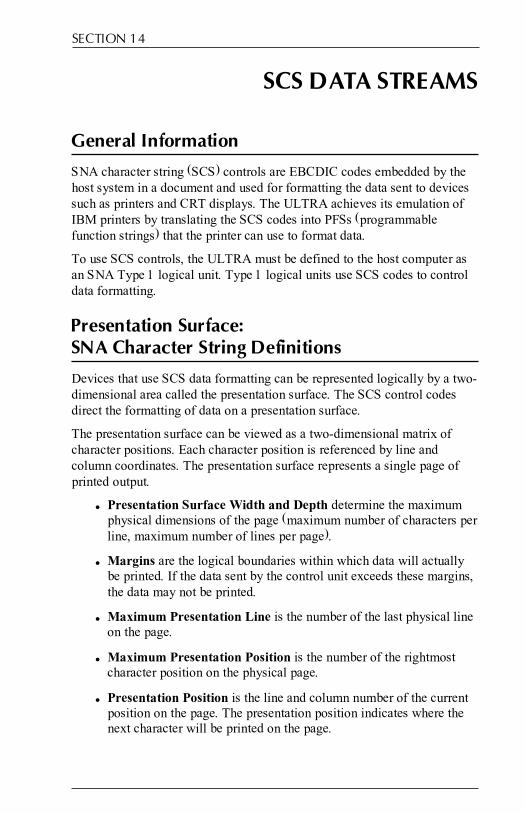
SCS DATA STREAMS
General Information
SNA character string (SCS) controls are EBCDIC codes embedded by thehost system in a document and used for formatting the data sent to devicessuch as printers and CRT displays. The ULTRA achieves its emulation ofIBM printers by translating the SCS codes into PFSs (programmablefunction strings) that the printer can use to format data.
To use SCS controls, the ULTRA must be defined to the host computer asan SNA Type 1 logical unit. Type 1 logical units use SCS codes to controldata formatting.
Presentation Surface:SNA Character String Definitions
Devices that use SCS data formatting can be represented logically by a two-dimensional area called the presentation surface. The SCS control codesdirect the formatting of data on a presentation surface.
The presentation surface can be viewed as a two-dimensional matrix ofcharacter positions. Each character position is referenced by line andcolumn coordinates. The presentation surface represents a single page ofprinted output.
� Presentation Surface Width and Depth determine the maximumphysical dimensions of the page (maximum number of characters perline, maximum number of lines per page).
� Margins are the logical boundaries within which data will actuallybe printed. If the data sent by the control unit exceeds these margins,the data may not be printed.
� Maximum Presentation Line is the number of the last physical lineon the page.
� Maximum Presentation Position is the number of the rightmostcharacter position on the physical page.
� Presentation Position is the line and column number of the currentposition on the page. The presentation position indicates where thenext character will be printed on the page.
SECTION 14

6287 ULTRA User�s ManualPage 14-2
SCS Commands Supported by the ULTRA
Application programs running on the host computer generate data streamsthat contain both the data to be printed and the SCS commands that controlthe positioning of the data on the page, as indicated below. This sectiondiscusses how to use the SCS commands supported by the ULTRA.
Backspace (BS) � 16h
The Backspace command moves the presentation position horizontally oneposition to the left. If already at the leftmost position, this command resultsin no operation. Upon receipt of an SCS 16h in the data stream, the ULTRAwill send an ASCII BS (08h) to printer, if the print position is not already atthe left margin.
End of Message (EM) � 19h
An End of Message generates a new line, except when it occurs in the firstprinting column, dependent upon the setting of Option 52.
Form Feed (FF) � 0Ch
The Form Feed command moves the presentation position to the top andleft margins of the next page.
Horizontal Tab (HT) � 05h
The Horizontal Tab command moves the presentation position horizontallyto the next tab stop to the right. The horizontal tab stops are determined bythe Set Horizontal Format command. Tab commands are translated into theappropriate number of spaces and sent to the printer. If there are nohorizontal tab stops to the right of the current position, the HT is treated asa space character.
Interchange File Separator (IFS) � 1Ch
One of four Interchange Separator Commands used to delimit informationstrings in SCS data streams. The ULTRA interprets it as a space.
Interchange Group Separator (IGS) � 1Dh
The ULTRA interprets this Interchange Separator as a space.

Page 14-3SCS DATA STREAMS
Interchange Record Separator (IRS) � 1Eh
The ULTRA interprets this Interchange Separator as a new line.
Interchange Unit Separator (IUS) � 1Fh
The ULTRA interprets this Interchange Separator as a space.
Line Feed (LF) � 25h
The Line Feed command moves the presentation position down to the nextline. The column position remains the same. Option #3 � Line Spacingmay cause the ULTRA to move down more than one line.
Null � 00h
The Null command is converted to a space by the ULTRA.
Set Horizontal Format (SHF) � 2BC1h
The Set Horizontal Format command is used to set left and right margins,horizontal tab stops that are used by the horizontal tab command, and to setthe maximum presentation position for the page. The SHF command hasmultiple parameters in the following format:
(SHF)(CNT)(MPP)(LM)(RM)(T1)...(TN) Where:
SHF The Set Horizontal Format command code = 2BC1h
CNT A Count of the number of bytes in this command string,including the count byte.
MPP The maximum width of the print line. Default is the linelength of the physical device.
LM The character position of the Left Margin. LM is also the firsthorizontal tab stop. The LM value must be less than or equalto MPP. The default is 1.
RM The character position of the Right Margin. The value of theRM must be greater than LM and less than or equal to MPP.
T1-TN The character positions of the horizontal tab stops, if any.Valid tab stops are less than or equal to the value of MPP.The tab stops do not have to be in any particular order.
Note: All parameters are single byte binary numbers.
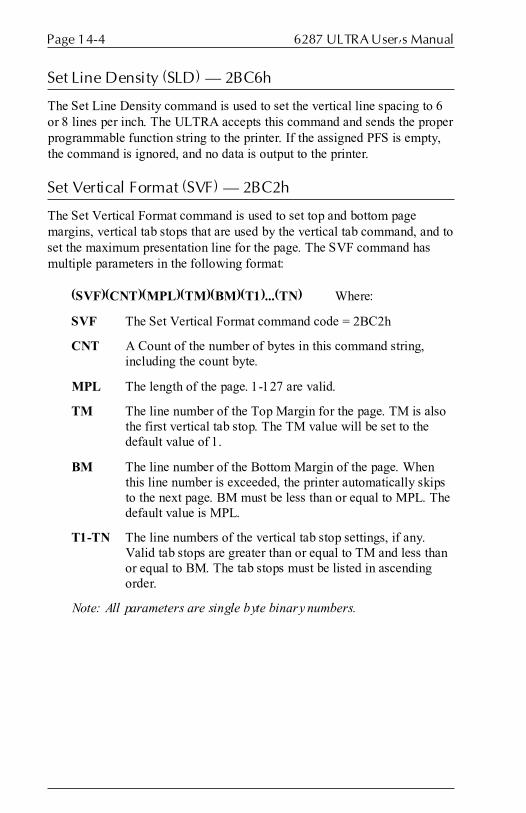
6287 ULTRA User�s ManualPage 14-4
Set Line Density (SLD) � 2BC6h
The Set Line Density command is used to set the vertical line spacing to 6or 8 lines per inch. The ULTRA accepts this command and sends the properprogrammable function string to the printer. If the assigned PFS is empty,the command is ignored, and no data is output to the printer.
Set Vertical Format (SVF) � 2BC2h
The Set Vertical Format command is used to set top and bottom pagemargins, vertical tab stops that are used by the vertical tab command, and toset the maximum presentation line for the page. The SVF command hasmultiple parameters in the following format:
(SVF)(CNT)(MPL)(TM)(BM)(T1)...(TN) Where:
SVF The Set Vertical Format command code = 2BC2h
CNT A Count of the number of bytes in this command string,including the count byte.
MPL The length of the page. 1-127 are valid.
TM The line number of the Top Margin for the page. TM is alsothe first vertical tab stop. The TM value will be set to thedefault value of 1.
BM The line number of the Bottom Margin of the page. Whenthis line number is exceeded, the printer automatically skipsto the next page. BM must be less than or equal to MPL. Thedefault value is MPL.
T1-TN The line numbers of the vertical tab stop settings, if any.Valid tab stops are greater than or equal to TM and less thanor equal to BM. The tab stops must be listed in ascendingorder.
Note: All parameters are single byte binary numbers.

Page 14-5SCS DATA STREAMS
Transparent (TRN) � 35h
The Transparent command indicates the start of transparent data. This datais not scanned for SCS control codes. The command is followed by a countbyte that indicates the number of bytes of transparent data to follow. Thecommand has the following format:
(TRN)(CNT) Where:
TRN is the Transparent command code 35h.
CNT is a single binary byte denoting the number of bytes in thetransparent block. The Count value does not include thecount byte.
The Transparent command is especially important because it gives the userthe ability to generate any possible 8 bit command or data byte to be outputto the attached device. Many of the extended 8 bit ASCII command codesused by printers and plotters must be transmitted as transparent data streamsbecause they cannot be generated or passed through the IBM systemwithout being modified. Each byte of data is sent to the printer withouttranslation. For example, the following 8 bit EBCDIC codes are the RESETcommand for a Xerox laser printer:
35031B2B58
35 is the transparent command code, 03 is the count of the data bytes to besent to the attached device, and 1B, 2B and 58 are the three bytes to be sentto the attached device.
Vertical Tab (VT) � 0Bh
The Vertical Tab command moves the presentation position down to thenext vertical tab stop position. The vertical tab stops are determined by theSet Vertical Format command. If no vertical tab stop exists below thecurrent line, the VT is treated as a line feed.
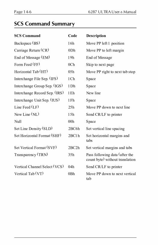
6287 ULTRA User�s ManualPage 14-6
SCS Command Summary
SCS Command Code Description
Backspace (BS) 16h Move PP left 1 position
Carriage Return (CR) 0Dh Move PP to left margin
End of Message (EM) 19h End of Message
Form Feed (FF) 0Ch Skip to next page
Horizontal Tab (HT) 05h Move PP right to next tab stop
Interchange File Sep. (IFS) 1Ch Space
Interchange Group Sep. (IGS) 1Dh Space
Interchange Record Sep. (IRS) 1Eh New line
Interchange Unit Sep. (IUS) 1Fh Space
Line Feed (LF) 25h Move PP down to next line
New Line (NL) 15h Send CR/LF to printer
Null 00h Space
Set Line Density (SLD) 2BC6h Set vertical line spacing
Set Horizontal Format (SHF) 2BC1h Set horizontal margins andtabs
Set Vertical Format (SVF) 2BC2h Set vertical margins and tabs
Transparency (TRN) 35h Pass following data (after thecount byte) without translation
Vertical Channel Select (VCS) 04h Send CR/LF to printer
Vertical Tab (VT) 0Bh Move PP down to next verticaltab
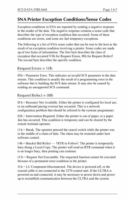
Page 14-7SCS DATA STREAMS
SNA Printer Exception Conditions/Sense Codes
Exception conditions in SNA are reported by sending a negative responseto the sender of the data. The negative response contains a sense code thatdescribes the type of exception condition that occurred. Some of theseconditions are errors, and some are just temporary exceptions.
The following is a list of SNA sense codes that can be sent to the host as theresult of an exception condition involving a printer. Sense codes are madeup of two bytes of information. The first byte describes the class ofexception that occurred (10h for Request Errors, 08h for Request Reject).The second byte describes the specific condition.
Request Errors = 10h
05h = Parameter Error. This indicates an invalid SCS parameter in the datastream. This condition is usually the result of a programming error in thesoftware that is building the SCS data stream. It may also be caused bysending an unsupported SCS command.
Request Reject = 08h
01h = Resource Not Available. Either the printer is configured for local use,or an outbound pacing overrun has occurred. This is a networkconfiguration problem that should be referred to the systems programmer.
02h = Intervention Required. Either the printer is out of paper, or a paperjam has occurred. This condition is temporary and can be cleared by theremote terminal operator.
11h = Break. The operator pressed the cancel switch while the printer wasin the middle of a chain of data. The chain may be restarted under hostsoftware control.
14h = Bracket Bid Reject � (RTR to Follow). The printer is temporarilybusy doing a Local Copy. The printer will send an RTR command when itis no longer busy, then printing can continue.
1Ch = Request Not Executable. The requested function cannot be executedbecause of a permanent error condition in the printer.
31h = LU Component Disconnected. The device is powered off, or thecoaxial cable is not connected to the 3270 control unit. If the ULTRA ispowered on and connected, it may be necessary to power down and powerup to reestablish communication between the ULTRA and the system.


DSC DATA STREAMS
General Information
The DSC (Data Stream Compatibility) character set is found in non-SNAenvironments. It has a limited number of control characters, which areexplained below.
Carriage Return (CR) � 05h
This command moves the presentation position to the left margin.
End of Message (EM) � 01h
The End of Message command terminates printing, and it may also send anew line to the printer, depending upon the setting of Option # 51 � DSCEM Generates CR/LF in Infinite Line Length and Option #57 � DSC NLat EM Even if in Column 1, and upon whether or not the current printposition is column 1. Here is a table listing all of the possible results:
OPTION 51 OPTION 57 COLUMN RESULT
N N 1 No new lineN N >1 Send new lineN Y 1 Send new lineN Y >1 Send new lineY N 1 No new lineY N >1 Send new lineY Y 1 Send new lineY Y >1 Send new line
Form Feed (FF) � 02h
The Form Feed command moves the presentation position to the top andleft margins of the next page.
New Line (NL) � 03h
The New Line command moves the presentation position to the next lineand left margin of the page. If the line count exceeds the bottom margin, theULTRA will send an FF to the printer, and the print position will be the leftand top margins of the next page.
SECTION 15


XEROX APPLICATIONS
General Information
Xerox distributed printers supported by the ULTRA include the followingmodels: 2700, 3700, 4030, 4045, 4197, 4213, 4235 and 4700. The ULTRAhas a number of special features that support Xerox printer functions. Forinstance, it supports output to Xerox printers using the EBCDIC characterset.
The ULTRA also supports Xerox transparency, triggered by 36h in the datastream. Refer to Option #5 in Section 5 � Configuration Options and toSection 11 � Transparency Modes for details on Xerox 36h transparency.
Other special Xerox features supported include UDKs (user-defined keys),XPAF (Graphic Windows and EBCDIC font downloads) and Metacode.ULTRA implementation of these features is described below.
User-Defined Keys (UDKs)
Xerox Corporation produces a number of printers that have verysophisticated font and graphic capabilities. The ULTRA offers specialsupport for Xerox printers in XDPM mode, also referred to as XES mode orUDK mode. XES mode is the native Xerox print mode for Xerox 2700,3700, 4030, 4045 and 4213 printers. The XDPM mode on the Xerox 4235also provides the XES command set.
Commands that control these printers are always preceded by an escapecharacter. The escape character is sometimes not a legal character in amainframe environment. Therefore, UDKs (or user-defined keys) wereimplemented to allow any one of 256 different characters to be assigned asthe escape character. The ULTRA keeps track of which character iscurrently being used as the UDK.
Note: The character assigned as the UDK should be different than thecharacter assigned as pseudo transparency Trigger 1. Otherwise,unpredictable results may occur.
SECTION 16

6287 ULTRA User�s ManualPage 16-2
XPAF Support
XPAF (Xerox Printer Access Facility) accepts Advanced Function PrintingData Stream (AFPDS) data and converts it for use by Xerox printers (4030,2700, 4045, 3700, etc.). When installed for use with one of these printers,XPAF expects to see a 3287-like device (such as the ULTRA) at the end ofthe coax cable.
These data types are sometimes corrupted by host system forms control.The ULTRA takes this fact into consideration and strips away any formscontrol that might corrupt these data types.
The ULTRA is capable of supporting two important XPAF features. Theseare EBCDIC fonts and EBCDIC graphic windows. Originally intended forEBCDIC printers, these sequences can be sent to an ASCII printer whenattached to the ULTRA.
The ULTRA�s support of XPAF allows the protocol converter to be inASCII output mode at all times. This is an important feature to ULTRAusers that require the alternate host port(s) for PC-type data.
The ULTRA contains special translate tables to accommodate this feature.(These are not related to the user-definable translate tables referred toelsewhere in this manual. They are located in ROM and are unchangeable.)When either a font or graphic window is detected, these translate tables arein effect. At the end of the font or graphic window, the translate table isswitched to the one in effect before the graphic window or font wasdetected.
Xerox Graphic Window Support
When the ULTRA sees (UDK/Esc)gw, a graphic window is beingprocessed. The (UDK) is the user-defined key. Please refer to the Xeroxprinter programmer reference for further information on this escapesequence.
If the user�s application requires this feature, and if the user would like touse the printer in ASCII mode, this option should be set to �Yes.� Refer toOption #60 in Section 5 � Configuration Options.
Note: If the ULTRA is in EBCDIC output mode (see Option #10), Option#60 must be set to �No.�
Page 16-3XEROX APPLICATIONS
Allow EBCDIC Font Downloading
When the ULTRA sees (UDK/Esc)+A or (UDK/Esc)+F, a font download isbeing processed. The (UDK) is the user-defined key. Please refer to theXerox printer programmer reference for further information on this escapesequence.
If the user�s application requires this feature, and if the user would like touse the printer in ASCII mode, this option should be set to �Yes.� Refer toOption #62 in Section 5 � Configuration Options.
Note: If the ULTRA is in EBCDIC output mode (see Option #10), Option#62 must be set to �No.�
Metacode Support
Some Xerox printers are capable of accepting Metacode data. The Xerox4235 is a Metacode-capable printer, for example. The data seen by theULTRA and the printer are identical when this type of data is detected.Metacode data is triggered by a 35h in the data stream, immediatelyfollowed by a count byte, then the data itself. The data is not translated inthis sequence. Additional information can be found in Section 11 �Transparency Modes. Please refer to the Xerox printer programmerreference for further information on this escape sequence.
Refer to Option #58 in Section 5 � Configuration Options. Users withapplications that require a Metacode-capable printer should set this optionto �Yes.�


SECTION 17
ALTERNATE HOSTCONSIDERATIONS
General Information
Many types of devices can be attached to the alternate host port of theULTRA. Alternate hosts may include PCs, minicomputers such as a DECVAX or a Burroughs, network servers, print-sharing devices and even otherprotocol converters. This section discusses how to ensure compatibilitybetween the alternate host, coax host and the printer.
Activating the Alternate Host Port
The alternate host port is disabled by default. To activate the alternate hostport, Option #50 must be configured by the user. Refer to Section 5 �Configuration Options. The choices for Option #50 are (A) OFF, (B) Bothparallel and serial alternate hosts, (C) Serial alternate host and (D) Parallelalternate host. Make the appropriate choice, referring for instructions toSection 8 � Front Panel Configuration or Section 9 � Coax HostConfiguration.
Configuring the Alternate Host Port
The dip switches on the ULTRA back panel are also used to configure theunit for an alternate host. The dip switch default settings (all switches in theOFF/up position) are appropriate for a parallel alternate host.
If using a serial alternate host, the settings of dip switch Bank B must bechanged. Refer to Section 3 � Dip Switch Settings for information on theappropriate configuration.
Note: Users with both parallel and serial alternate hosts will have tochange the dip switch settings and press the RESET button on the ULTRAfront panel when switching between parallel and serial alternate hosts. Toconnect both parallel and serial alternate hosts also requires the use ofAGILE�s special �Y� alternate host adapter.
6287 ULTRA User�s ManualPage 17-2
Host Lockout Duration
When the ULTRA, the printer and the alternate host are powered on, thecoax host port and the alternate host port are available until a print job isreceived. When a print job is received from either port, the ULTRA willprocess that data and allow the other port to remain available.
To manage data simultaneously from an alternate host plus a coax hostrequires the ULTRA to sense when each device has finished printing.Otherwise, data from the coax host might be mixed with data from analternate host. A timing mechanism is used to manage the host ports. TheULTRA will switch between coax host and alternate host print jobs afterboth the print job is done and a user-defined lockout period has elapsed.
Refer to Section 5 � Configuration Options. Option #40 � Alternate HostLockout Duration specifies the number of seconds during a print job thatthe ULTRA will wait without receiving a character before allowing anotherhost to control the output port. If no characters are printed from the currenthost for three seconds (the default), the ULTRA is placed in neutral, andany host may take control. Longer delays may be required to accommodateslow printers or slow input devices.
Make the appropriate choice, referring for instructions to Section 8 � FrontPanel Configuration or Section 9 � Coax Host Configuration. (Once thealternate host port is activated and otherwise configured, this option can bechanged via the alternate host itself. Refer to Section 10 � Alternate HostConfiguration for instructions.) The appropriate time can be determinedonly by trial and error. If too long a delay is entered, switching betweenhosts may take longer than is necessary. If too short a delay time (0 to 10) isentered for the lockout duration, two print jobs could become intermixed orcorrupted, because the ULTRA will switch between the coax host andalternate host after each data block is processed.
If data is sent to a port before the current host has finished printing, theport will show a busy condition until the ULTRA is placed in neutral. If theULTRA receives a print job from the alternate host and the coax hostsimultaneously, the coax host print job will be printed first. The first 240characters of the alternate host print job will be buffered until the host printjob is done.
Some alternate host hardware and software systems are incapable ofinternally queueing a print job, and they will �lock up� if they send a printjob while a coax host job is being printed. The lock-up condition willcontinue until the coax host print job is completed; then the alternate hostjob will be printed.
Page 17-3ALTERNATE HOST CONSIDERATIONS
Alternate Host Translation
The data stream from the alternate host is not sent directly through theULTRA to the attached printer. Rather, all characters must first passthrough the appropriate translate table, even if the printer uses the same dataformat as the alternate host.
If both the printer and the alternate host use the ASCII character set, thedata is passed through Translate Table #3 � ASCII to ASCII. If using aXerox printer in EBCDIC mode, the data will be converted with TranslateTable #6 � ASCII to EBCDIC. For more information, refer to Section 7 �Translate Tables.
Although these tables may be edited by the user, AGILE advises againstdoing so, particularly because these tables are also used to generateconfiguration reports, and changing them may corrupt output to the printer.
Other Considerations
The connection between the alternate host and the ULTRA may be testedby sending a print screen job to the printer. Users with problems in printingproperly formatted documents from the alternate host may print a bufferdump of the data being sent from the alternate host to the printer. Refer toSection 4 � Troubleshooting for details on printing these reports.
If using a serial alternate host that is configured to use CTS (Clear to Send)flow control � also known as �hardware� handshaking, Option #41 mustbe set to �Yes� (the default setting). If the serial alternate host uses XON/XOFF (software) handshaking, set this option to �No.� For parallelinterfacing, this option can be ignored. Make the appropriate choice,referring for instructions to Section 8 � Front Panel Configuration orSection 9 � Coax Host Configuration.
The only other configuration options that will affect printed output from thealternate host are Option #10 � Output in ASCII or EBCDIC and Option#25 � Centronics or Dataproducts Parallel, but these are configured toconform to the printer and its interface and are not specific to the alternatehost. Otherwise, data is sent from the alternate host to the printer withoutany transformation, so the alternate host software requirements are the sameas they would be if the alternate host were attached directly to the printer.As such, all page formatting (e.g., column width, line spacing, form feeds,etc.) must be handled by the alternate host software application.


APPENDIX
General Information
The Appendix contains samples of the General Configuration Report,Printer Test, Auto Buffer Report, Translate Table Report and Alternate HostBuffer Dump. A pin-out chart of the ULTRA ports is also included.
General Configuration Report
The following is a sample of the General Configuration Report with allfactory defaults selected. Print this report by pressing the TEST button onthe ULTRA front panel. This report should be printed before and aftermaking any configuration changes or when troubleshooting the ULTRA.
SECTION 18

6287 ULTRA User�s ManualPage 18-2
Agile 6287UltraVersion 46.00 - 8344 -Dip A:00 Dip B:00*����==< PRINTER FORMAT >==����* *������������������* 1)column width (0 = infinite)...[132] 2)lines per page................[000] 3)line spacing..................[001] 4)null line suppression y/n.....[Y] *������������������*
5)xerox 36h transparency y/n....[N] *���==< PRINTER INTERFACE >==��* 6)local copy form feed - before.[N] 25)parallel: a)cent b)dataprod..[A] 7)local copy form feed - after..[Y] 26)intervention required y/n....[Y] 8)newline order a)cr/lf b)lf/cr.[A] 27)intervention requireddelay..[010] 9)pa key usage a)normal b)pfs...[A] 10)output in a)ascii or b)ebcdic.[A] 11)apl output? y/n...............[N] 12)dumps to a)same, b)other port.[A] 13)supress spaces before ptm?....[N] 14)supress carriage ctrl chars?..[N]
*��==< BOLD PRINT EMULATION >==��* 15)a)3287 b)displaywrite c)none..[C] 16)supress leading spaces?.......[N]*���==< PRINTER EMULATION >==���* PHYSICAL BUFFER SIZE: 20)a)2k b)2keab c)4k d)4keab..[C] LOGICAL BUFFER SIZE: 21)a)960 b)1920 c)2560 d)3440 e)3564..[D]Custom Banner: : :Power on Sequence: : :PFS #1: : :PFS #2: : :PFS #3: : :PFS #4: : :PFS #5: : :PFS #6: : :PA1 key: : :PA2 key: : :BOLD ON: : :BOLD OFF: : :
COAX Host PFS: : :ALT Host PFS: : :BEGIN BRACKET PFS: : :SSA PFS: : :

Page 18-3APPENDIX
TRAY 1: : :TRAY 2: : :TRAY 3: : :MAN. FEED: : :ENV. TRAY: : : *������������������* 30)transp. a)regular b)count.....[A] 31)discard transp. delimiter y/n.[N]
32)dsc transp. trigger 1.........[1B] *������������������* 33)dsc transp. trigger 2.........[1A]
34)scs transp. trigger 1.........[4A] 35)scs transp. trigger 2.........[5B]
36)ascii transp. trigger 1.......[1B] 37)ascii transp. trigger 2.......[24] 38)ascii apl trigger character...[1A]
39)transp. trigger 1 output......[9B]
*������������������*
40)duration of lockout in seconds.[016]
41)serial cts handshaking? y/n....[Y] *������������������*
*������������������*
47)Carriage Control Exits PTM.....[Y]
48)Continuous bell a,b,c, or d?...[A] *������������������*
49)C0 05 header elimination? y/n..[N] *������������������*
50)Alt host a,b,c, or d?..........[A] *������������������*
51)NL @ DSC EM even in infinite...[N] *������������������*
52)Ignore SCS EM if in column 1...[N] *������������������*
53)Ignore 35h transparency? y/n...[N] *������������������*
54)Idle POR after (seconds).......[000] *������������������*
55)MD-Laser supported? y/n........[N] *������������������*
57)NL @ DSC EM even in column 1?..[N] *������������������*
58)Metacode supported?............[N] *������������������*
59)Laser Page supported?..........[N] *������������������*
60)Xerox graphic window support?..[N] *������������������*
62)Allow EBCDIC font downloads?...[N] *������������������*

6287 ULTRA User�s ManualPage 18-4
Printer Test
This page contains a sample Printer Test. A printer test checks theconnection between the ULTRA and the printer. In performing this test, theULTRA sends the printer a continuous stream of characters, includingalphabetic, numeric and special characters. To print this test, put dip switchA2 in the ON (down) position, and press the RESET button on the ULTRAfront panel. To end the test, put dip switch A2 in the OFF (down) position,then press the RESET button. For more information, refer to Section 4 �Troubleshooting.
!�#$%&�()*+,-. 0123456789:;<=>?@ABCDEFGHIJKLMNOPQRSTUVWXYZ[\]^_�abcdefghijklmnopqrstuvwxyz{|}~ !�#$%&�()*+,-./0123456789:;<=>?@ABCDEFGHIJKLMNOPQRSTUVWXYZ[\]^_�abcdefghijklmnopqrstuvwxyz{|}~ !�#$%&�()*+,-./0123456789:;<=>?@ABCDEFGHIJKLMNOPQRSTUVWXYZ[\]^_�abcdefghijklmnopqrstuvwxyz{|}~ !�#$%&�()*+,-./0123456789:;<=>?@ABCDEFGHIJKLMNOPQRSTUVWXYZ[\]^_�abcdefghijklmnopqrstuvwxyz{|}~ !�#$%&�()*+,-./0123456789:;<=>?@ABCDEFGHIJKLMNOPQRSTUVWXYZ[\]^_�abcdefghijklmnopqrstuvwxyz{|}~ !�#$%&�()*+,-./0123456789:;<=>?@ABCDEFGHIJKLMNOPQRSTUVWXYZ[\]^_�abcdefghijklmnopqrstuvwxyz{|}~ !�#$%&�()*+,-./0123456789:;<=>?@ABCDEFGHIJKLMNOPQRSTUVWXYZ[\]^_�abcdefghijklmnopqrstuvwxyz{|}~ !�#$%&�()*+,-./0123456789:;<=>?@ABCDEFGHIJKLMNOPQRSTUVWXYZ[\]^_�abcdefghijklmnopqrstuvwxyz{|}~ !�#$%&�()*+,-./0123456789:;<=>?@ABCDEFGHIJKLMNOPQRSTUVWXYZ[\]^_�abcdefghijklmnopqrstuvwxyz{|}~ !�#$%&�()*+,-./0123456789:;<=>?@ABCDEFGHIJKLMNOPQRSTUVWXYZ[\]^_�abcdefghijklmnopqrstuvwxyz{|}~ !�#$%&�()*+,-./0123456789:;<=>?@ABCDEFGHIJKLMNOPQRSTUVWXYZ[\]^_�abcdefghijklmnopqrstuvwxyz{|}~ !�#$%&�()*+,-./0123456789:;<=>?@ABCDEFGHIJKLMNOPQRSTUVWXYZ[\]^_�abcdefghijklmnopqrstuvwxyz{|}~ !�#$%&�()*+,-./0123456789:;<=>?@ABCDEFGHIJKLMNOPQRSTUVWXYZ[\]^_�abcdefghijklmnopqrstuvwxyz{|}~ !�#$%&�()*+,-./0123456789:;<=>?@ABCDEFGHIJKLMNOPQRSTUVWXYZ[\]^_�abcdefghijklmnopqrstuvwxyz{|}~ !�#$%&�()*+,-./0123456789:;<=>?@ABCDEFGHIJKLMNOPQRSTUVWXYZ[\]^_�abcdefghijklmnopqrstuvwxyz{|}~ !�#$%&�()*+,-./0123456789:;<=>?@ABCDEFGHIJKLMNOPQRSTUVWXYZ[\]^_�abcdefghijklmnopqrstuvwxyz{|}~ !�#$%&�()*+,-./0123456789:;<=>?@ABCDEFGHIJKLMNOPQRSTUVWXYZ[\]^_�abcdefghijklmnopqrstuvwxyz{|}~ !�#$%&�()*+,-./0123456789:;<=>?@ABCDEFGHIJKLMNOPQRSTUVWXYZ[\]^_�abcdefghijklmnopqrstuvwxyz{|}~ !�#$%&�()*+,-./0123456789:;<=>?@ABCDEFGHIJKLMNOPQRSTUVWXYZ[\]^_�abcdefghijklmnopqrstuvwxyz{|}~ !�#$%&�()*+,-./0123456789:;<=>?@ABCDEFGHIJKLMNOPQRSTUVWXYZ[\]^_�abcdefghijklmnopqrstuvwxyz{|}~ !�#$%&�()*+,-./0123456789:;<=>?@ABCDEFGHIJKLMNOPQRSTUVWXYZ[\]^_�abcdefghijklmnopqrstuvwxyz{|}~ !�#$%&�()*+,-./0123456789:;<=>?@ABCDEFGHIJKLMNOPQRSTUVWXYZ[\]^_�abcdefghijklmnopqrstuvwxyz{|}~ !�#$%&�()*+,-./0123456789:;<=>?@ABCDEFGHIJKLMNOPQRSTUVWXYZ[\]^_�abcdefghijklmnopqrstuvwxyz{|}~ !�#$%&�()*+,-./0123456789:;<=>?@ABCDEFGHIJKLMNOPQRSTUVWXYZ[\]^_�abcdefghijklmnopqrstuvwxyz{|}~ !�#$%&�()*+,-./0123456789:;<=>?@ABCDEFGHIJKLMNOPQRSTUVWXYZ[\]^_�abcdefghijklmnopqrstuvwxyz{|}~ !�#$%&�()*+,-./0123456789:;<=>?@ABCDEFGHIJKLMNOPQRSTUVWXYZ[\]^_�abcdefghijklmnopqrstuvwxyz{|}~ !�#$%&�()*+,-./0123456789:;<=>?@ABCDEFGHIJKLMNOPQRSTUVWXYZ[\]^_�abcdefghijklmnopqrstuvwxyz{|}~ !�#$%&�()*+,-./0123456789:;<=>?@ABCDEFGHIJKLMNOPQRSTUVWXYZ[\]^_�abcdefghijklmnopqrstuvwxyz{|}~ !�#$%&�()*+,-./0123456789:;<=>?@ABCDEFGHIJKLMNOPQRSTUVWXYZ[\]^_�abcdefghijklmnopqrstuvwxyz{|}~ !�#$%&�()*+,-./0123456789:;<=>?@ABCDEFGHIJKLMNOPQRSTUVWXYZ[\]^_�abcdefghijklmnopqrstuvwxyz{|}~ !�#$%&�()*+,-./0123456789:;<=>?@ABCDEFGHIJKLMNOPQRSTUVWXYZ[\]^_�abcdefghijklmnopqrstuvwxyz{|}~ !�#$%&�()*+,-./0123456789:;<=>?@ABCDEFGHIJKLMNOPQRSTUVWXYZ[\]^_�abcdefghijklmnopqrstuvwxyz{|}~ !�#$%&�()*+,-./0123456789:;<=>?@ABCDEFGHIJKLMNOPQRSTUVWXYZ[\]^_�abcdefghijklmnopqrstuvwxyz{|}~ !�#$%&�()*+,-./0123456789:;<=>?@ABCDEFGHIJKLMNOPQRSTUVWXYZ[\]^_�abcdefghijklmnopqrstuvwxyz{|}~ !�#$%&�()*+,-./0123456789:;<=>?@ABCDEFGHIJKLMNOPQRSTUVWXYZ[\]^_�abcdefghijklmnopqrstuvwxyz{|}~ !�#$%&�()*+,-./0123456789:;<=>?@ABCDEFGHIJKLMNOPQRSTUVWXYZ[\]^_�abcdefghijklmnopqrstuvwxyz{|}~ !�#$%&�()*+,-./0123456789:;<=>?@ABCDEFGHIJKLMNOPQRSTUVWXYZ[\]^_�abcdefghijklmnopqrstuvwxyz{|}~ !�#$%&�()*+,-./0123456789:;<=>?@ABCDEFGHIJKLMNOPQRSTUVWXYZ[\]^_�abcdefghijklmnopqrstuvwxyz{|}~ !�#$%&�()*+,-./0123456789:;<=>?@ABCDEFGHIJKLMNOPQRSTUVWXYZ[\]^_�abcdefghijklmnopqrstuvwxyz{|}~ !�#$%&�()*+,-./0123456789:;<=>?@ABCDEFGHIJKLMNOPQRSTUVWXYZ[\]^_�abcdefghijklmnopqrstuvwxyz{|}~ !�#$%&�()*+,-./0123456789:;<=>?@ABCDEFGHIJKLMNOPQRSTUVWXYZ[\]^_�abcdefghijklmnopqrstuvwxyz{|}~ !�#$%&�()*+,-./0123456789:;<=>?@ABCDEFGHIJKLMNOPQRSTUVWXYZ[\]^_�abcdefghijklmnopqrstuvwxyz{|}~ !�#$%&�()*+,-./0123456789:;<=>?@ABCDEFGHIJKLMNOPQRSTUVWXYZ[\]^_�abcdefghijklmnopqrstuvwxyz{|}~ !�#$%&�()*+,-./0123456789:;<=>?@ABCDEFGHIJKLMNOPQRSTUVWXYZ[\]^_�abcdefghijklmnopqrstuvwxyz{|}~ !�#$%&�()*+,-./0123456789:;<=>?@ABCDEFGHIJKLMNOPQRSTUVWXYZ[\]^_�abcdefghijklmnopqrstuvwxyz{|}~ !�#$%&�()*+,-./0123456789:;<=>?@ABCDEFGHIJKLMNOPQRSTUVWXYZ[\]^_�abcdefghijklmnopqrstuvwxyz{|}~ !�#$%&�()*+,-./0123456789:;<=>?@ABCDEFGHIJKLMNOPQRSTUVWXYZ[\]^_�abcdefghijklmnopqrstuvwxyz{|}~ !�#$%&�()*+,-./0123456789:;<=>?@ABCDEFGHIJKLMNOPQRSTUVWXYZ[\]^_�abcdefghijklmnopqrstuvwxyz{|}~ !�#$%&�()*+,-./0123456789:;<=>?@ABCDEFGHIJKLMNOPQRSTUVWXYZ[\]^_�abcdefghijklmnopqrstuvwxyz{|}~ !�#$%&�()*+,-./0123456789:;<=>?@ABCDEFGHIJKLMNOPQRSTUVWXYZ[\]^_�abcdefghijklmnopqrstuvwxyz{|}~ !�#$%&�()*+,-./0123456789:;<=>?@ABCDEFGHIJKLMNOPQRSTUVWXYZ[\]^_�abcdefghijklmnopqrstuvwxyz{|}~ !�#$%&�()*+,-./0123456789:;<=>?@ABCDEFGHIJKLMNOPQRSTUVWXYZ[\]^_�abcdefghijklmnopqrstuvwxyz{|}~ !�#$%&�()*+,-./0123456789:;<=>?@ABCDEFGHIJKLMNOPQRSTUVWXYZ[\]^_�abcdefghijklmnopqrstuvwxyz{|}~ !�#$%&�()*+,-./0123456789:;<=>?@ABCDEFGHIJKLMNOPQRSTUVWXYZ[\]^_�abcdefghijklmnopqrstuvwxyz{|}~

Page 18-5APPENDIX
Auto Buffer Report
This page and the next two pages contain a sample Auto Buffer Report.This report is useful for analyzing data streams, and it will sometimes berequested by AGILE technical support when diagnosing printing problems.The data presented by this report is a buffer dump of the data that theULTRA receives, along with a printout of the host print job being sent tothe printer.
To print this report, put dip switch A8 in the ON (down) position, and pressthe RESET button on the ULTRA front panel. Then send a local copy ortypical mainframe print job to the printer. After the report has finishedprinting, set dip switch A8 in the OFF (up) position, then press the RESETbutton.
SSA
Agile 6287UltraVersion 46.00 - 8344 -Dip A:80 Dip B:00 x0 x1 x2 x3 x4 x5 x6 x7 x8 x9 xA xB xC xD xE xF0000 00 00 00 00 00 00 00 00 00 00 00 00 1F 10 00 000010 00 15 00 50 07 81 03 05 50 00 00 00 00 00 00 000020 00 00 00 00 00 00 00 00 00 00 00 00 00 00 00 000030 00 00 FF 00 FF 00 FF 00 FF 00 FF 00 FF 00 FF 000040 00 00 00 00 00 00 00 00 00 00 04 31 74 CC 00 000050 F0 AC A0 A8 AD 00 00 00 00 00 00 F0 00 00 00 00 M A I N0060 00 00 00 00 00 00 00 00 00 00 00 00 00 00 00 F8
0070 A0 B2 14 24 20 20 10 AC 80 88 8D 10 AC 84 8D 94 A S / 4 0 0 M a i n M e n u0080 F0 00 00 00 00 00 00 00 00 00 00 00 00 00 00 00
00D0 00 00 00 00 00 00 00 00 00 00 00 00 F0 B2 98 92 S y s00E0 93 84 8C 34 F0 00 F0 B2 21 20 22 20 22 29 28 F0 t e m : S 1 0 2 0 2 9 800F0 F0 B2 84 8B 84 82 93 10 8E 8D 84 10 8E 85 10 93 S e l e c t o n e o f t0100 87 84 10 85 8E 8B 8B 8E 96 88 8D 86 34 F0 00 00 h e f o l l o w i n g :0190 00 00 00 00 00 F0 21 32 00 B4 92 84 91 10 93 80 1 . U s e r t a

6287 ULTRA User�s ManualPage 18-6
01A0 92 8A 92 F0 00 00 00 00 00 00 00 00 00 00 00 00 s k s01E0 00 00 00 00 00 F0 22 32 00 AE 85 85 88 82 84 10 2 . O f f i c e01F0 93 80 92 8A 92 F0 00 00 00 00 00 00 00 00 00 00 t a s k s0230 00 00 00 00 00 F0 23 32 00 A6 84 8D 84 91 80 8B 3 . G e n e r a l0240 10 92 98 92 93 84 8C 10 93 80 92 8A 92 F0 00 00 s y s t e m t a s k s0280 00 00 00 00 00 F0 24 32 00 A5 88 8B 84 92 33 10 4 . F i l e s ,0290 8B 88 81 91 80 91 88 84 92 33 10 80 8D 83 10 85 l i b r a r i e s , a n d f02A0 8E 8B 83 84 91 92 F0 00 00 00 00 00 00 00 00 00 o l d e r s02D0 00 00 00 00 00 F0 25 32 00 AF 91 8E 86 91 80 8C 5 . P r o g r a m02E0 8C 88 8D 86 F0 00 00 00 00 00 00 00 00 00 00 00 m i n g0320 00 00 00 00 00 F0 26 32 00 A2 8E 8C 8C 94 8D 88 6 . C o m m u n i0330 82 80 93 88 8E 8D 92 F0 00 00 00 00 00 00 00 00 c a t i o n s0370 00 00 00 00 00 F0 27 32 00 A3 84 85 88 8D 84 10 7 . D e f i n e0380 8E 91 10 82 87 80 8D 86 84 10 93 87 84 10 92 98 o r c h a n g e t h e s y0390 92 93 84 8C F0 00 00 00 00 00 00 00 00 00 00 00 s t e m03C0 00 00 00 00 00 F0 28 32 00 AF 91 8E 81 8B 84 8C 8 . P r o b l e m03D0 10 87 80 8D 83 8B 88 8D 86 F0 00 00 00 00 00 00 h a n d l i n g0410 00 00 00 00 00 F0 29 32 00 A3 88 92 8F 8B 80 98 9 . D i s p l a y0420 10 80 10 8C 84 8D 94 F0 00 00 00 00 00 00 00 00 a m e n u0460 00 00 00 00 F0 21 20 32 00 B4 92 84 91 10 92 94 1 0 . U s e r s u0470 8F 8F 8E 91 93 10 80 8D 83 10 84 83 94 82 80 93 p p o r t a n d e d u c a t0480 88 8E 8D F0 00 00 00 00 00 00 00 00 00 00 00 00 i o n04B0 00 00 00 00 F0 21 21 32 00 AF A2 10 B2 94 8F 8F 1 1 . P C S u p p04C0 8E 91 93 10 93 80 92 8A 92 F0 00 00 00 00 00 00 o r t t a s k s

Page 18-7APPENDIX
0550 00 00 00 00 F0 29 20 32 00 B2 88 86 8D 10 8E 85 9 0 . S i g n o f0560 85 F0 00 00 00 00 00 00 00 00 00 00 00 00 00 00 f05F0 F0 B2 84 8B 84 82 93 88 8E 8D 10 8E 91 10 82 8E S e l e c t i o n o r c o0600 8C 8C 80 8D 83 F0 00 00 00 00 00 00 00 00 00 00 m m a n d0640 F0 11 11 11 08 C0 00 00 00 00 00 00 00 00 00 00 = = = >06D0 00 00 00 00 00 00 00 00 00 00 00 00 00 00 00 F0
06E0 F0 A5 23 11 A4 97 88 93 F0 00 F0 A5 24 11 AF 91 F 3 = E x i t F 4 = P r06F0 8E 8C 8F 93 F0 00 F0 A5 29 11 B1 84 93 91 88 84 o m p t F 9 = R e t r i e0700 95 84 F0 00 F0 A5 21 22 11 A2 80 8D 82 84 8B F0 v e F 1 2 = C a n c e l0710 00 F0 A5 21 23 11 B4 92 84 91 10 92 94 8F 8F 8E F 1 3 = U s e r s u p p o0720 91 93 F0 00 00 00 00 00 00 00 00 00 00 00 00 00 r t0730 F0 A5 22 23 11 B2 84 93 10 88 8D 88 93 88 80 8B F 2 3 = S e t i n i t i a l0740 10 8C 84 8D 94 F0 00 00 00 00 00 00 00 00 00 00 m e n u0780 F8 0D A2 0C 10 A2 AE AF B8 B1 A8 A6 A7 B3 10 A8 ( C ) C O P Y R I G H T I0790 A1 AC 10 A2 AE B1 AF 32 10 21 29 28 20 33 10 21 B M C O R P . 1 9 8 0 , 107A0 29 29 21 32 00 00 00 00 00 00 00 00 00 00 00 00 9 9 1 .07C0 00 00 00 00 00 00 00 00 00 00 00 00 00 F8 00 00
07D0 F0 00 00 00 00 00 00 00 00 00 00 00 00 00 00 00
SSA

6287 ULTRA User�s ManualPage 18-8
Alternate Host Buffer Dump
This page and the next two pages contain a sample Alternate Host BufferDump. This report can be useful for determining the casues of problemsthat may occur in sending properly formatted documents to the printer fromthe alternate host, and AGILE technical support may request this reportwhen troubleshooting the ULTRA. The data presented by this report issimilar to the information presented in an Auto Buffer Report.
To send this report, set dip switches B6, B7 and B8 in the ON (down)position, then press the RESET button on the ULTRA front panel. Print theoffending document from the alternate host. After the document hasfinished printing, set dip switches B6, B7 and B8 to their former locations,and press the RESET button on the ULTRA front panel.
0000 1B 26 6C 32 34 63 31 45 1B 26 6C 30 4F 1B 28 30 0010 55 1B 28 73 30 70 31 30 68 31 32 76 30 73 30 62 0020 33 54 1B 26 6C 36 44 1B 2A 70 78 36 35 59 20 20 0030 20 20 41 47 49 4C 45 20 58 2F 54 52 41 20 56 31 0040 2E 32 32 20 4E 6F 76 20 31 34 20 31 39 39 35 20 0050 31 34 3A 32 32 3A 32 32 20 43 6F 70 79 72 69 67 0060 68 74 20 28 63 29 20 31 39 39 33 2C 31 39 39 35 0070 20 62 79 20 41 47 49 4C 45 2E 0D 0A 1B 2A 70 58 0080 20 20 20 20 20 20 20 20 20 20 20 20 20 20 20 20 0090 20 20 20 20 20 20 20 20 20 20 43 6F 6E 66 69 67 00A0 75 72 61 74 69 6F 6E 20 2F 20 53 74 61 74 75 73 00B0 20 50 61 67 65 1B 2A 70 78 59 1B 2A 63 32 34 30 00C0 30 61 31 34 56 1B 2A 63 30 50 1B 2A 70 78 31 35 00D0 30 59 1B 2A 63 32 34 30 30 61 31 34 56 1B 2A 63 00E0 30 50 1B 2A 70 78 33 30 30 30 59 1B 2A 63 32 34 00F0 30 30 61 31 34 56 1B 2A 63 30 50 1B 28 30 55 1B 0100 28 73 30 70 31 30 68 31 32 76 30 73 30 62 33 54 0110 0D 1B 2A 70 35 30 78 32 37 35 59 1B 26 61 32 4C 0120 0D 0D 50 72 69 6E 74 65 72 3A 0D 0A 20 1B 28 30 0130 55 1B 28 73 30 70 31 36 2E 36 36 68 38 2E 35 76 0140 30 73 30 62 30 54 55 6E 6B 6E 6F 77 6E 1B 28 30 0150 55 1B 28 73 30 70 31 30 68 31 32 76 30 73 30 62 0160 33 54 0D 0A 20 20 4D 61 78 20 4D 65 6D 6F 72 79 0170 3A 20 30 0D 0A 41 76 61 69 6C 20 4D 65 6D 6F 72 0180 79 3A 20 30 0D 0A 0D 0A 58 2F 54 52 41 3A 0D 0A 0190 20 20 52 41 4D 20 53 69 7A 65 3A 20 32 35 36 4B 01A0 1B 26 6C 36 44 0D 0A 1B 26 61 32 4C 0D 46 4C 41 01B0 53 48 20 53 69 7A 65 3A 20 31 32 38 4B 1B 26 6C 01C0 36 44 0D 0A 1B 28 30 55 1B 28 73 30 70 31 30 68 01D0 31 32 76 30 73 30 62 33 54 0D 0A 1B 26 61 4C 0D 01E0 1B 2A 70 35 30 58 43 75 72 72 65 6E 74 3A 1B 26 01F0 61 32 4C 1B 26 6C 36 44 0D 0A 1B 28 30 55 1B 28

Page 18-9APPENDIX
0200 73 30 70 31 36 2E 36 36 68 38 2E 35 76 30 73 30 0210 62 30 54 1B 26 6C 35 43 20 20 20 20 20 20 20 20 0220 20 20 20 46 6F 6E 74 20 3A 20 58 43 50 31 34 69 0230 73 6F 2D 4C 20 20 20 20 20 20 20 20 20 20 0D 0A 0240 20 20 20 53 74 61 74 75 73 20 73 68 65 65 74 20 0250 3A 20 52 65 71 75 65 73 74 0D 0A 20 50 6F 77 65 0260 72 2D 55 70 20 73 68 65 65 74 20 3A 20 4F 6E 0D 0270 0A 20 20 20 20 45 72 72 6F 72 20 4C 65 76 65 6C 0280 20 3A 20 50 61 72 73 65 20 45 72 72 6F 72 0D 0A 0290 20 20 20 20 20 20 20 4C 61 6E 67 75 61 67 65 20 02A0 3A 20 55 2E 53 2E 20 45 6E 67 6C 69 73 68 0D 0A 02B0 20 20 20 20 20 20 20 50 44 4C 20 4D 6F 64 65 20 02C0 3A 20 58 45 53 0D 0A 20 20 20 20 4C 69 6E 65 20 02D0 65 6E 64 69 6E 67 20 3A 20 41 75 74 6F 20 43 52 02E0 2C 4C 46 2C 43 52 2F 4C 46 0D 0A 20 20 46 6F 6E 02F0 74 20 72 6F 74 61 74 69 6F 6E 20 3A 20 4F 6E 0D 0300 0A 20 20 20 20 20 49 6E 70 75 74 20 74 72 61 79 0310 20 3A 20 31 0D 0A 20 20 20 20 4F 75 74 70 75 74 0320 20 74 72 61 79 20 3A 20 30 0D 0A 20 20 20 20 50 0330 61 67 65 20 6C 65 6E 67 74 68 20 3A 20 36 36 30 0340 0D 0A 20 20 20 20 20 54 6F 70 20 6D 61 72 67 69 0350 6E 20 3A 20 34 30 0D 0A 20 20 42 6F 74 74 6F 6D 0360 20 6D 61 72 67 69 6E 20 3A 20 34 30 0D 0A 20 20 0370 20 20 4C 65 66 74 20 6D 61 72 67 69 6E 20 3A 20 0380 32 34 0D 0A 20 20 20 52 69 67 68 74 20 6D 61 72 0390 67 69 6E 20 3A 20 34 38 36 0D 0A 20 20 20 20 50 03A0 72 69 6E 74 20 73 69 64 65 73 20 3A 20 53 69 6D 03B0 70 6C 65 78 0D 0A 20 20 20 20 20 20 20 20 20 20 03C0 55 6E 69 74 73 20 3A 20 36 30 74 68 73 0D 0A 20 03D0 20 4A 75 73 74 69 66 69 63 61 74 69 6F 6E 20 3A 03E0 20 4F 66 66 0D 0A 20 20 20 4C 69 6E 65 20 73 70 03F0 61 63 69 6E 67 20 3A 20 4F 6E 65 0D 0A 55 70 70 0400 65 72 43 61 73 65 20 43 6D 6E 64 73 20 3A 20 49 0410 6E 76 61 6C 69 64 0D 0A 53 69 7A 65 20 43 6F 72 0420 72 65 63 74 69 6F 6E 20 3A 20 53 68 72 69 6E 6B 0430 0D 0A 1B 28 30 55 1B 28 73 30 70 31 30 68 31 32 0440 76 30 73 30 62 33 54 1B 2A 70 37 35 30 78 32 37 0450 35 59 46 6F 6E 74 73 3A 1B 26 6C 36 44 0D 0A 1B 0460 28 30 55 1B 28 73 30 70 31 36 2E 36 36 68 38 2E 0470 35 76 30 73 30 62 30 54 1B 26 6C 35 43 1B 26 61 0480 34 37 4C 0D 20 20 54 69 74 61 6E 31 30 69 73 6F 0490 2D 4C 20 20 20 20 20 20 20 20 28 53 29 0D 0A 20 04A0 20 54 69 74 61 6E 31 30 69 73 6F 2D 50 20 20 20 04B0 20 20 20 20 20 28 53 29 0D 0A 20 20 54 69 74 61 04C0 6E 31 32 69 73 6F 2D 4C 20 20 20 20 20 20 20 20 04D0 28 53 29 0D 0A 20 20 54 69 74 61 6E 31 32 69 73 04E0 6F 2D 50 20 20 20 20 20 20 20 20 28 53 29 0D 0A 04F0 20 20 58 43 50 31 34 69 73 6F 2D 4C 20 20 20 20
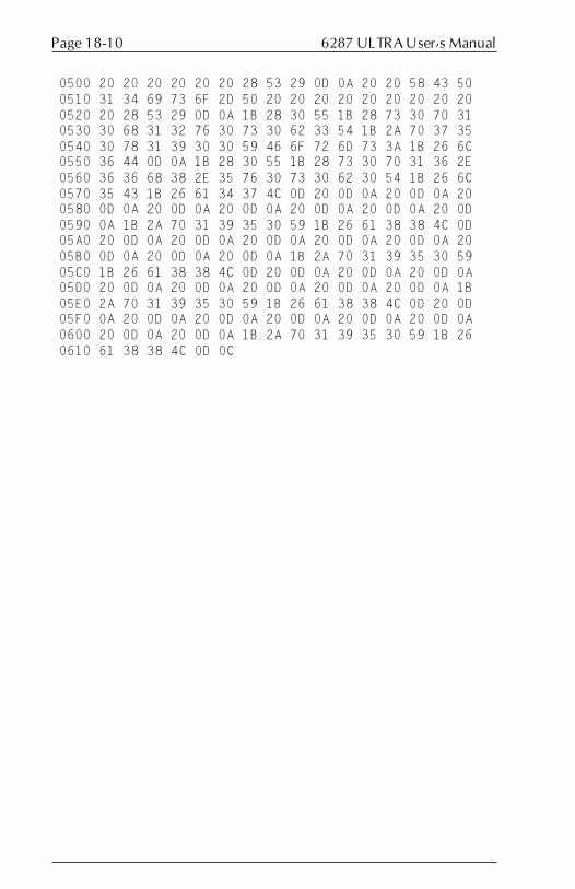
6287 ULTRA User�s ManualPage 18-10
0500 20 20 20 20 20 20 28 53 29 0D 0A 20 20 58 43 50 0510 31 34 69 73 6F 2D 50 20 20 20 20 20 20 20 20 20 0520 20 28 53 29 0D 0A 1B 28 30 55 1B 28 73 30 70 31 0530 30 68 31 32 76 30 73 30 62 33 54 1B 2A 70 37 35 0540 30 78 31 39 30 30 59 46 6F 72 6D 73 3A 1B 26 6C 0550 36 44 0D 0A 1B 28 30 55 1B 28 73 30 70 31 36 2E 0560 36 36 68 38 2E 35 76 30 73 30 62 30 54 1B 26 6C 0570 35 43 1B 26 61 34 37 4C 0D 20 0D 0A 20 0D 0A 20 0580 0D 0A 20 0D 0A 20 0D 0A 20 0D 0A 20 0D 0A 20 0D 0590 0A 1B 2A 70 31 39 35 30 59 1B 26 61 38 38 4C 0D 05A0 20 0D 0A 20 0D 0A 20 0D 0A 20 0D 0A 20 0D 0A 20 05B0 0D 0A 20 0D 0A 20 0D 0A 1B 2A 70 31 39 35 30 59 05C0 1B 26 61 38 38 4C 0D 20 0D 0A 20 0D 0A 20 0D 0A 05D0 20 0D 0A 20 0D 0A 20 0D 0A 20 0D 0A 20 0D 0A 1B 05E0 2A 70 31 39 35 30 59 1B 26 61 38 38 4C 0D 20 0D 05F0 0A 20 0D 0A 20 0D 0A 20 0D 0A 20 0D 0A 20 0D 0A 0600 20 0D 0A 20 0D 0A 1B 2A 70 31 39 35 30 59 1B 26 0610 61 38 38 4C 0D 0C

Page 18-11APPENDIX
Translate Table Report
The following pages contain a sample Translate Table Report, with alldefault values indicated. This report should be printed before and aftermaking any modifications to the translate tables.
To print a Translate Table Report, set dip switch B7 in the ON (down)position, press the RESET button on the ULTRA front panel, then press theCANCEL button. After the report has finished printing, set dip switch B7 toits former position, and press the RESET button on the ULTRA front panel.
Agile 6287UltraVersion 46.00 - 8344 -Dip A:00 Dip B:40 DSC (COAX) TO ASCII........ MSN-> 0X 1X 2X 3X 4X 5X 6X 7X 8X 9X AX BX CX DX EX FX LSN-v |�����������������������- X0|05 05 30 26 2D 2D 2D 2D 61 71 41 51 20 20 20 20 X1|05 3D 31 2D 2D 2D 2D 2D 62 72 42 52 20 20 20 20 X2|05 27 32 2E 2D 2D 2D 2D 63 73 43 53 20 20 20 20 X3|05 22 33 2C 2D 2D 2D 2D 64 74 44 54 20 20 20 20 X4|2D 2F 34 3A 2D 2D 2D 2D 65 75 45 55 20 20 20 20 X5|05 5C 35 2B 2D 2D 2D 2D 66 76 46 56 20 20 20 20 X6|2D 7C 36 5E 2D 2D 2D 2D 67 77 47 57 20 20 20 20 X7|2D 99 37 2D 2D 2D 2D 2D 68 78 48 58 20 20 20 20 X8|3E 3F 38 2D 2D 2D 2D 2D 69 79 49 59 20 20 20 20 X9|3C 21 39 2D 2D 2D 2D 2D 6A 7A 4A 5A 20 20 20 20 XA|5B 24 2D 5E 2D 2D 2D 2D 6B 2D 4B 2D 20 20 20 20 XB|5D 05 7E 7E 2D 2D 2D 2D 6C 2D 4C 2D 20 20 20 20 XC|29 2D 23 2D 2D 2D 2D 2D 6D 2D 4D 2D 20 20 20 20 XD|28 2D 40 60 2D 2D 2D 2D 6E 2D 4E 2D 20 20 20 20 XE|7D 2D 25 27 2D 2D 2D 2D 6F 2D 4F 3B 20 20 20 20 XF|7B 2D 5F 2D 2D 2D 2D 2D 70 2D 50 2A 20 20 20 20
SCS (COAX/ALT) TO ASCII........ MSN-> 0X 1X 2X 3X 4X 5X 6X 7X 8X 9X AX BX CX DX EX FX LSN-v |�����������������������- X0|20 20 20 20 20 26 2D 2D 2D 2D 2D 2D 7B 7D 5C 30 X1|20 20 20 20 2D 2D 2F 2D 61 6A 7E 2D 41 4A 2D 31 X2|20 20 20 20 2D 2D 2D 2D 62 6B 73 2D 42 4B 53 32 X3|20 20 20 20 2D 2D 2D 2D 63 6C 74 2D 43 4C 54 33 X4|05 20 20 20 2D 2D 2D 2D 64 6D 75 2D 44 4D 55 34 X5|05 05 05 05 2D 2D 2D 2D 65 6E 76 2D 45 4E 56 35 X6|20 05 20 20 2D 2D 2D 2D 66 6F 77 2D 46 4F 57 36 X7|20 20 1B 20 2D 2D 2D 2D 67 70 78 2D 47 50 58 37 X8|05 20 05 20 2D 2D 2D 2D 68 71 79 2D 48 51 59 38 X9|20 05 20 20 2D 2D 2D 60 69 72 7A 2D 49 52 5A 39 XA|20 20 20 20 05 21 7C 3A 2D 2D 2D 2D 2D 2D 2D 2D XB|05 20 05 20 2E 24 2C 23 2D 2D 2D 2D 2D 2D 2D 2D XC|05 20 20 20 3C 2A 25 40 2D 2D 2D 2D 2D 2D 2D 2D XD|05 20 20 20 28 29 5F 27 2D 2D 5B 5D 2D 2D 2D 2D XE|20 05 20 20 2B 3B 3E 3D 2D 2D 2D 2D 2D 2D 2D 2D XF|20 20 20 20 7C 5E 3F 22 2D 2D 2D 2D 2D 2D 2D 2D

6287 ULTRA User�s ManualPage 18-12
DSC (COAX) TO EBCDIC....... MSN-> 0X 1X 2X 3X 4X 5X 6X 7X 8X 9X AX BX CX DX EX FX LSN-v |�����������������������- X0|05 05 F0 50 57 75 9E B7 81 98 C1 D8 40 40 40 40 X1|05 7E F1 60 58 76 9F B8 82 99 C2 D9 40 40 40 40 X2|05 7D F2 4B 59 77 A0 B9 83 A2 C3 E2 40 40 40 40 X3|05 7F F3 6B 62 78 AA BA 84 A3 C4 E3 40 40 40 40 X4|60 61 F4 7A 63 80 AB BB 85 A4 C5 E4 40 40 40 40 X5|05 E0 F5 4E 64 8A AC BC 86 A5 C6 E5 40 40 40 40 X6|ED 4F F6 5F 65 8B 41 42 87 A6 C7 E6 40 40 40 40 X7|EE 6A F7 49 66 8C AE BE 88 A7 C8 E7 40 40 40 40 X8|6E 6F F8 51 67 8D AF BF 89 A8 C9 E8 40 40 40 40 X9|4C 5A F9 52 68 8E B0 CA 91 A9 D1 E9 40 40 40 40 XA|AD 5B 47 53 69 8F B1 CB 92 E1 D2 FA 40 40 40 40 XB|BD 05 48 A1 70 90 B2 CC 93 EA D3 FB 40 40 40 40 XC|5D 43 7B 54 CE 9A B3 CD 94 EB D4 FC 40 40 40 40 XD|4D 44 7C 79 CF 9B B4 DF 95 EC D5 FD 40 40 40 40 XE|D0 45 6C 55 DD 9C B5 DB 96 EF D6 5E 40 40 40 40 XF|C0 46 6D 56 DE 9D B6 DC 97 FE D7 5C 40 40 40 40
SCS (COAX/ALT) TO EBCDIC....... MSN-> 0X 1X 2X 3X 4X 5X 6X 7X 8X 9X AX BX CX DX EX FX LSN-v |�����������������������- X0|00 10 20 30 40 50 60 70 80 90 A0 B0 C0 D0 E0 F0 X1|01 11 21 31 41 51 61 71 81 91 A1 B1 C1 D1 E1 F1 X2|02 12 22 32 42 52 62 72 82 92 A2 B2 C2 D2 E2 F2 X3|03 13 23 33 43 53 63 73 83 93 A3 B3 C3 D3 E3 F3 X4|04 14 24 34 44 54 64 74 84 94 A4 B4 C4 D4 E4 F4 X5|05 05 05 05 45 55 65 75 85 95 A5 B5 C5 D5 E5 F5 X6|06 05 26 36 46 56 66 76 86 96 A6 B6 C6 D6 E6 F6 X7|07 17 27 37 47 57 67 77 87 97 A7 B7 C7 D7 E7 F7 X8|05 18 05 38 48 58 68 78 88 98 A8 B8 C8 D8 E8 F8 X9|09 05 29 39 49 59 69 79 89 99 A9 B9 C9 D9 E9 F9 XA|0A 1A 2A 3A 05 5A 6A 7A 8A 9A AA BA CA DA EA FA XB|05 1B 05 3B 4B 5B 6B 7B 8B 9B AB BB CB DB EB FB XC|05 1C 2C 3C 4C 5C 6C 7C 8C 9C AC BC CC DC EC FC XD|05 1D 2D 3D 4D 5D 6D 7D 8D 9D AD BD CD DD ED FD XE|0E 05 2E 3E 4E 5E 6E 7E 8E 9E AE BE CE DE EE FE XF|0F 1F 2F 3F 4F 5F 6F 7F 8F 9F AF BF CF DF EF FF

Page 18-13APPENDIX
DSC (COAX) TO ASCII APL.... MSN-> 0X 1X 2X 3X 4X 5X 6X 7X 8X 9X AX BX CX DX EX FX LSN-v |�����������������������- X0|05 FF FF FF FF AE 7D 7B FC FF FF FF FF FF FF FF X1|05 FF FF FF A1 AF A3 BA FF FF FF FF FF FF FF FF X2|05 FF FF FF E7 B0 A4 BB C7 FF E6 9E FF FF FF FF X3|05 FF FF FF E8 B1 A5 C0 C8 FF 9B 21 FF FF FF FF X4|FF FF FF FF E9 B2 A6 C1 C9 FF ED FF FF FF FF FF X5|05 FF FF FF F0 B3 A7 BD D0 FF EE FF FF FF FF FF X6|FF FF FF FF F1 B4 A8 BC D1 FF FB DC FF FF FF FF X7|FF FF FF FF F2 B6 F8 C4 D2 FF FD DD FF FF FF FF X8|FF FF FF FF F3 5C AA C5 D3 FF EF FF FF FF FF FF X9|FF FF FF FF F5 B8 AB C6 D4 FF E1 FF FF FF FF FF XA|FF FF FF FF F7 F9 FF FF FF FF CA DE FF FF FF FF XB|FF 05 FF FF A0 C3 FF FF FF FF CB DF FF FF FF FF XC|FF FF FF FF AD A9 FF FF FF FF 5E FF FF FF FF FF XD|FF FF FF FF C2 5D FF FF FF FF E4 B5 FF FF FF FF XE|FF FF FF FF AC BE FF F6 FF FF CC EA FF FF FF FF XF|FF FF FF FF 5B 7C FF FF FF FF CF EB FF FF FF FF
SCS (COAX/ALT) TO ASCII APL.... MSN-> 0X 1X 2X 3X 4X 5X 6X 7X 8X 9X AX BX CX DX EX FX LSN-v |�����������������������- X0|FF FF FF FF 8A CE FF FF B5 F1 A0 B0 7B 7D FF FF X1|FF FF FF FF A3 BA FF 5E AF FF AF B1 FF FF FF FF X2|FF FF FF FF A4 BB C7 9B FF FF 2D B2 E2 FF FF FF X3|FF FF FF FF A5 C0 C8 FF FF FF E0 B3 2B 2B FF FF X4|FF FF FF FF A6 C1 C9 FF FF FF 6E B4 FF FF FF FF X5|05 05 05 05 A7 BD D0 FF FF FF FF FF FF FF FF FF X6|FF 05 FF 80 A8 BC D1 FF FF FF FF B6 92 91 FF FF X7|FF FF 1B 81 F8 C4 D2 FF FF FF FF 5C AC A9 FF FF X8|FF FF 05 82 AA C5 D3 E4 FF FF FF B8 FF FF FF FF X9|FF 05 FF 83 AB C6 D4 FF FF FF FF FF FF FF FF FF XA|FF FE FF 84 05 EC FF FF A1 F2 AD F9 CA 9E EA FF XB|05 FF 05 85 8B FF FF FF E6 F3 C2 C3 CB 21 EB FB XC|05 FF FF 86 8C FF FF FF E7 90 AC A9 FF DC EC FC XD|05 FF FF 87 8D FF FF FF E8 F5 5B 5D CC DD ED FD XE|FF 05 FF 88 8E FF FF FF E9 F6 AE BE FF DE EE E1 XF|FF FF FF 89 8F F4 FF FF F0 F7 9F 7C CF DF EF FF
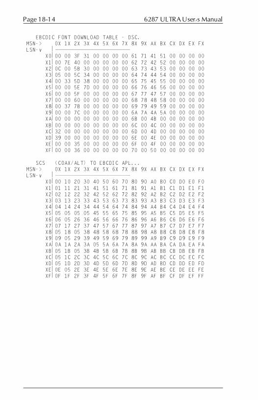
6287 ULTRA User�s ManualPage 18-14
EBCDIC FONT DOWNLOAD TABLE - DSC. MSN-> 0X 1X 2X 3X 4X 5X 6X 7X 8X 9X AX BX CX DX EX FX LSN-v |�����������������������- X0|00 00 3F 31 00 00 00 00 61 71 41 51 00 00 00 00 X1|00 7E 40 00 00 00 00 00 62 72 42 52 00 00 00 00 X2|0C 00 5B 30 00 00 00 00 63 73 43 53 00 00 00 00 X3|05 00 5C 34 00 00 00 00 64 74 44 54 00 00 00 00 X4|00 33 5D 38 00 00 00 00 65 75 45 55 00 00 00 00 X5|00 00 5E 7D 00 00 00 00 66 76 46 56 00 00 00 00 X6|00 00 5F 00 00 00 00 00 67 77 47 57 00 00 00 00 X7|00 00 60 00 00 00 00 00 68 78 48 58 00 00 00 00 X8|00 37 7B 00 00 00 00 00 69 79 49 59 00 00 00 00 X9|00 00 7C 00 00 00 00 00 6A 7A 4A 5A 00 00 00 00 XA|00 00 00 00 00 00 00 00 6B 00 4B 00 00 00 00 00 XB|00 00 00 00 00 00 00 00 6C 00 4C 00 00 00 00 00 XC|32 00 00 00 00 00 00 00 6D 00 4D 00 00 00 00 00 XD|39 00 00 00 00 00 00 00 6E 00 4E 00 00 00 00 00 XE|00 00 35 00 00 00 00 00 6F 00 4F 00 00 00 00 00 XF|00 00 36 00 00 00 00 00 70 00 50 00 00 00 00 00
SCS (COAX/ALT) TO EBCDIC APL... MSN-> 0X 1X 2X 3X 4X 5X 6X 7X 8X 9X AX BX CX DX EX FX LSN-v |�����������������������- X0|00 10 20 30 40 50 60 70 80 90 A0 B0 C0 D0 E0 F0 X1|01 11 21 31 41 51 61 71 81 91 A1 B1 C1 D1 E1 F1 X2|02 12 22 32 42 52 62 72 82 92 A2 B2 C2 D2 E2 F2 X3|03 13 23 33 43 53 63 73 83 93 A3 B3 C3 D3 E3 F3 X4|04 14 24 34 44 54 64 74 84 94 A4 B4 C4 D4 E4 F4 X5|05 05 05 05 45 55 65 75 85 95 A5 B5 C5 D5 E5 F5 X6|06 05 26 36 46 56 66 76 86 96 A6 B6 C6 D6 E6 F6 X7|07 17 27 37 47 57 67 77 87 97 A7 B7 C7 D7 E7 F7 X8|05 18 05 38 48 58 68 78 88 98 A8 B8 C8 D8 E8 F8 X9|09 05 29 39 49 59 69 79 89 99 A9 B9 C9 D9 E9 F9 XA|0A 1A 2A 3A 05 5A 6A 7A 8A 9A AA BA CA DA EA FA XB|05 1B 05 3B 4B 5B 6B 7B 8B 9B AB BB CB DB EB FB XC|05 1C 2C 3C 4C 5C 6C 7C 8C 9C AC BC CC DC EC FC XD|05 1D 2D 3D 4D 5D 6D 7D 8D 9D AD BD CD DD ED FD XE|0E 05 2E 3E 4E 5E 6E 7E 8E 9E AE BE CE DE EE FE XF|0F 1F 2F 3F 4F 5F 6F 7F 8F 9F AF BF CF DF EF FF

Page 18-15APPENDIX
ASCII (ALT) TO ASCII........ MSN-> 0X 1X 2X 3X 4X 5X 6X 7X 8X 9X AX BX CX DX EX FX LSN-v |�����������������������- X0|00 10 20 30 40 50 60 70 80 90 A0 B0 C0 D0 E0 F0 X1|01 11 21 31 41 51 61 71 81 91 A1 B1 C1 D1 E1 F1 X2|02 12 22 32 42 52 62 72 82 92 A2 B2 C2 D2 E2 F2 X3|03 13 23 33 43 53 63 73 83 93 A3 B3 C3 D3 E3 F3 X4|04 14 24 34 44 54 64 74 84 94 A4 B4 C4 D4 E4 F4 X5|05 15 25 35 45 55 65 75 85 95 A5 B5 C5 D5 E5 F5 X6|06 16 26 36 46 56 66 76 86 96 A6 B6 C6 D6 E6 F6 X7|07 17 27 37 47 57 67 77 87 97 A7 B7 C7 D7 E7 F7 X8|08 18 28 38 48 58 68 78 88 98 A8 B8 C8 D8 E8 F8 X9|09 19 29 39 49 59 69 79 89 99 A9 B9 C9 D9 E9 F9 XA|0A 1A 2A 3A 4A 5A 6A 7A 8A 9A AA BA CA DA EA FA XB|0B 1B 2B 3B 4B 5B 6B 7B 8B 9B AB BB CB DB EB FB XC|0C 1C 2C 3C 4C 5C 6C 7C 8C 9C AC BC CC DC EC FC XD|0D 1D 2D 3D 4D 5D 6D 7D 8D 9D AD BD CD DD ED FD XE|0E 1E 2E 3E 4E 5E 6E 7E 8E 9E AE BE CE DE EE FE XF|0F 1F 2F 3F 4F 5F 6F 7F 8F 9F AF BF CF DF EF FF
ASCII (ALT) TO EBCDIC....... MSN-> 0X 1X 2X 3X 4X 5X 6X 7X 8X 9X AX BX CX DX EX FX LSN-v |�����������������������- X0|00 10 40 F0 7C D7 79 97 60 60 60 60 60 60 60 60 X1|01 11 5A F1 C1 D8 81 98 60 60 60 60 60 60 60 60 X2|02 12 7F F2 C2 D9 82 99 60 60 60 60 60 60 60 60 X3|03 13 7B F3 C3 E2 83 A2 60 60 60 60 60 60 60 60 X4|37 3C 5B F4 C4 E3 84 A3 60 60 60 60 60 60 60 60 X5|2D 3D 6C F5 C5 E4 85 A4 60 60 60 60 60 60 60 60 X6|15 32 50 F6 C6 E5 86 A5 60 60 60 60 60 60 60 60 X7|2F 26 7D F7 C7 E6 87 A6 60 60 60 60 60 60 60 60 X8|16 18 4D F8 C8 E7 88 A7 60 60 60 60 60 60 60 60 X9|05 19 5D F9 C9 E8 89 A8 60 60 60 60 60 60 60 60 XA|25 3F 5C 7A D1 E9 91 A9 60 60 60 60 60 60 60 60 XB|0B 27 4E 5E D2 AD 92 C0 60 60 60 60 60 60 60 60 XC|0C 22 6B 4C D3 E0 93 4F 60 60 60 60 60 60 60 60 XD|0D 1D 60 7E D4 BD 94 D0 60 60 60 60 60 60 60 60 XE|0E 1E 4B 6E D5 B5 95 A1 60 60 60 60 60 60 60 60 XF|0F 1F 61 6F D6 6D 96 07 60 60 60 60 60 60 60 60

6287 ULTRA User�s ManualPage 18-16
EBCDIC FONT DOWNLOAD TABLE - SCS. MSN-> 0X 1X 2X 3X 4X 5X 6X 7X 8X 9X AX BX CX DX EX FX LSN-v |�����������������������- X0|00 00 00 00 00 31 00 00 00 00 00 00 00 00 00 3F X1|00 00 00 00 00 00 33 00 61 6A 00 00 41 4A 00 40 X2|00 00 00 00 00 00 00 00 62 6B 73 00 42 4B 53 5B X3|00 00 00 00 00 00 00 00 63 6C 74 00 43 4C 54 5C X4|00 00 00 00 00 00 00 00 64 6D 75 00 44 4D 55 5D X5|00 05 00 00 00 00 00 00 65 6E 76 00 45 4E 56 5E X6|00 00 00 00 00 00 00 00 66 6F 77 00 46 4F 57 5F X7|00 00 00 00 00 00 00 00 67 70 78 00 47 50 58 60 X8|00 00 00 00 00 00 00 00 68 71 79 00 48 51 59 7B X9|00 00 00 00 00 00 00 00 69 72 7A 00 49 52 5A 7C XA|00 00 00 00 00 00 00 38 00 00 00 00 00 00 00 00 XB|00 00 00 00 30 00 34 00 00 00 00 00 00 00 00 00 XC|0C 00 00 00 00 00 35 00 00 00 00 00 00 00 00 00 XD|00 00 00 00 39 32 36 00 00 00 00 00 00 00 00 00 XE|00 00 00 00 7D 00 00 7E 00 00 00 00 00 00 00 00 XF|00 00 00 00 00 00 37 00 00 00 00 00 00 00 00 00
ASCII (ALT) TO EBCDIC APL... MSN-> 0X 1X 2X 3X 4X 5X 6X 7X 8X 9X AX BX CX DX EX FX LSN-v |�����������������������- X0|FF FF FF FF FF FF FF FF FF 9C A0 B0 53 65 A3 8F X1|FF FF DB FF FF FF FF FF FF D6 8A B1 54 66 FE 90 X2|FF FF FF FF FF FF FF FF FF C6 FF B2 AB 67 C2 9A X3|FF FF FF FF FF FF FF FF FF FF 41 B3 BB 68 FF 9B X4|FF FF FF FF FF FF FF FF FF FF 42 B4 57 69 78 FF X5|FF FF FF FF FF FF FF FF FF FF 43 80 58 FF FF 9D X6|FF FF FF FF FF FF FF FF FF FF 44 B6 59 FF 8B 9E X7|FF FF FF FF FF FF FF FF FF FF 45 FF 62 FF 8C 9F X8|FF FF FF FF FF FF FF FF FF FF 46 B8 63 FF 8D FF X9|FF FF FF FF FF FF FF FF FF FF 47 FF 64 FF 8E BA XA|FF FF FF FF FF FF FF FF 40 FF 48 51 CA FF EA FF XB|FF FF C3 FF FF B7 FF C0 FF 72 49 52 CB FF EB FB XC|FF FF FF FF FF BD FF BF FF FF AC 56 FF DC EC FC XD|FF FF A2 FF FF 71 FF D0 FF FF AA 55 CC DD ED FD XE|FF FF FF FF FF FF A4 FF FF DA AE BE 50 DE EE FF XF|FF FF FF FF FF FF FF FF FF AF A1 FF CF DF EF FF

Page 18-17APPENDIX
EDIT THE CUSTOM TEST DATA Y/N...... MSN-> 0X 1X 2X 3X 4X 5X 6X 7X 8X 9X AX BX CX DX EX FX LSN-v |�����������������������- X0|00 00 00 00 00 00 00 00 00 00 00 00 00 00 00 00 X1|00 00 00 00 00 00 00 00 00 00 00 00 00 00 00 00 X2|00 00 00 00 00 00 00 00 00 00 00 00 00 00 00 00 X3|00 00 00 00 00 00 00 00 00 00 00 00 00 00 00 00 X4|00 00 00 00 00 00 00 00 00 00 00 00 00 00 00 00 X5|00 00 00 00 00 00 00 00 00 00 00 00 00 00 00 00 X6|00 00 00 00 00 00 00 00 00 00 00 00 00 00 00 00 X7|00 00 00 00 00 00 00 00 00 00 00 00 00 00 00 00 X8|00 00 00 00 00 00 00 00 00 00 00 00 00 00 00 00 X9|00 00 00 00 00 00 00 00 00 00 00 00 00 00 00 00 XA|00 00 00 00 00 00 00 00 00 00 00 00 00 00 00 00 XB|00 00 00 00 00 00 00 00 00 00 00 00 00 00 00 00 XC|00 00 00 00 00 00 00 00 00 00 00 00 00 00 00 00 XD|00 00 00 00 00 00 00 00 00 00 00 00 00 00 00 00 XE|00 00 00 00 00 00 00 00 00 00 00 00 00 00 00 00 XF|00 00 00 00 00 00 00 00 00 00 00 00 00 00 00 00

6287 ULTRA User�s ManualPage 18-18
6287 ULTRA Port Pin-Out Charts
This page contains charts of the pin-out of the printer and alternate hostports of the 6287 ULTRA.
Alternate Host Input Port
12345678910111213
141516171819202122232425
1 = Chassis Ground
2 = TXD → (Transmit Data)
3 = RXD ← (Receive Data)
4 = RTS ← (Ready To Send)
5 = CTS → (Clear To Send)
6 = DSR ← (Data Set Ready)
7 = Signal Ground
8 = DCD ← (Data Carrier Detect)
20 = DTR → (Data Terminal Ready)
Serial Pin-Outs
9 = Data 1
10 = Data 2
12 = Printer Error (+)
13 = Data 3
14 = Data 4
Parallel Pin-Outs
15 = Select (+)
16 = Data 5
17 = Fault (-)
18 = Data 6
19 = Acknowledge (-)
21 = Data 7
22 = Data 8
23 = Strobe (-)
25 = Busy (+)

Page 18-19APPENDIX
Output Port
13121110987654321
252423222120191817161514
1 = Chassis Ground
2 = TXD → (Transmit Data)
3 = RXD ← (Receive Data)
4 = RTS ← (Ready To Send)
5 = CTS → (Clear To Send)
6 = DSR ← (Data Set Ready)
7 = Signal Ground
8 = DCD ← (Data Carrier Detect)
20 = DTR → (Data Terminal Ready)
Serial Pin-Outs
9 = Data 1
10 = Data 2
12 = Printer Error (+)
13 = Data 3
14 = Data 4
Parallel Pin-Outs
15 = Select (+)
16 = Data 5
17 = Fault (-)
18 = Data 6
19 = Acknowledge (-)
21 = Data 7
22 = Data 8
23 = Strobe (-)
24 = Init (-)
25 = Busy (+)


GLOSSARY
A
A/B switch A switch that allows input devices toshare a printer.
AFP Advanced Function Printing.
AFPDS Advanced Function Printing DataStream.
Alternate host Input devices other than the coax hostthat can use the printers attached to theULTRA, such as PCs, network servers,print sharing devices and even otherprotocol converters.
APL A Programming Language.
ASCII American Standard Code forInformation Interchange. A 7-bitstandard character code used forinterchanging data betweencommunications equipment.
B
Backspace Moves the print position one column tothe left.
Battery-backed RAM A non-volatile temporary means ofstorage. The ULTRA uses it to storeconfiguration parameters.
Baud rate A unit for measuring serial datatransmission speed.
Binary A base 2 numbering system.
Bit A binary digit. The smallest unit ofbinary information. Either a 0 or a 1.
BM Bottom margin.
BNC connector A type of coaxial cable end.
Bold A typestyle in which the strokes of thecharacters are thicker than normal.
SECTION 19

6287 ULTRA User�s ManualPage 19-2
Bottom margin The last line on which the ULTRA willallow a character to be printed.
Break An interruption of a transmission.
BS Backspace.
Buffer A block of internal memory that storesinformation until it is ready to be used.
Byte A unit of information consisting ofeight binary bits. Character codes areoften represented in bytes.
C
C0 05 header Two DSC characters that someapplications send to the printer.
Carriage Return A control character that (unless set to beinterpreted as a line end) causes theprinter to begin printing at the leftmargin of the current line.
Centronics The printer manufacturer that producedthe parallel interface that is now theindustry standard. Also used to refer tothe interface itself.
CICS/VS Customer Information Control System/Virtual System.
Cluster controller A down-line processor that collects datafrom a number of low-speed devices,then transmits the concentrated dataover a single communications channel.
CNT Count. The number of bytes in acommand string.
Coax Coaxial cable. The type of cable used tointerface the ULTRA with thecontroller. Standard RG62 A/U coax isrecommended for use in the 3270 IDS.
Column The vertical members of one line of anarray.
Configuration To assemble a collection of hardwareand software into a system and to

Page 19-3GLOSSARY
adjust each of the parts so they all work together.
Control code A byte of information representing aprint instruction (e.g., a tab).
Control Unit The portion of the CPU that directs thestep-by-step operation of the entirecomputing system.
Count byte A byte that indicates the number ofbytes to follow in an escape sequence.
CPI Characters per inch.
CR Carriage return.
CR/LF Carriage return/line feed.
CRT Cathode ray tube. A video displayterminal.
CTS Clear to send. A hardware handshakingmethod in serial interfacing.
D
Data bits Word length. The number of data bits ina word.
Data stream Information transmitted between thehost system and the ULTRA.
DB-25 A plug with 25 male or female pins,most commonly used with an RS-232-Cserial interface.
Decimal A base 10 numbering system.
Default Formatting configurations that arepresent and are used automaticallywhen no other information is available.
Delimit To mark the beginning and end of acharacter string.
Diagnostic A routine designed to verify theoperation of a system and to find amalfunction in a device.
Dip switch Dual In-line Package switch. Used onthe ULTRA rear panel to modify thefunctions of the unit.

6287 ULTRA User�s ManualPage 19-4
DisplayWrite 370 An IBM word processing applicationthat supports bolding, underlining andoverstriking.
DPA Display printer adapter.
DSC Data stream compatible. A pre-SNAprotocol.
E
EAB Extended Attribute Buffer. A featurefound in many IBM printers thatextends the number of charactersavailable for transmission to the printer.
EBCDIC Extended Binary Coded DecimalInterchange Code. An eight bitcharacter code.
EC Establishment controller.
EM character End of message marker.
Emulation A hardware or software productimitating the function of anotherhardware or software product.
End of Message A character that represents the lastcharacter of a message.
EPROM Erasable programmable read-onlymemory. The storage medium for theULTRA firmware.
Esc Escape control character. A non-graphic(unimaged) code that signals thetransmission of control information tothe ULTRA.
Establishment controller See �cluster controller.�
Exception condition A printing problem in an SNAenvironment.
Extended ASCII Some printer manufacturers haveimplemented their own version of 8 bittransmission. Extended ASCII allows128 additional characters to bedisplayed by the printer.

Page 19-5GLOSSARY
F
FCC Federal Communications Commission.
FF Form feed.
Firmware The pre-programmed EPROMsinstalled in the ULTRA (the internalsoftware).
Flow control Serial communication handshaking.
Form feed A control code that instructs the printerto process the current page and print it;a page end. The physical transport ofpaper to the beginning of a new page.
G
GDDM Graphical Data Display Manager. AnIBM graphics software product.
GML Graphic Machine Language.
Graphic Windows A feature of Xerox printers.
H
Handshaking An exchange of signals between twodevices in a computer network, as aprelude to data exchange. The methodof flow control used in serialinterfacing.
Hardware Any physical device in a computernetwork.
Hewlett-Packard A California company that produces awide range of computer equipment andperipherals.
Hexadecimal A base 16 numbering system. Numbersare represented using digits 0-9 andletters A-F.
Horizontal tab Moves the presentation positionhorizontally to the next tab stop to theright.
Host The system that transmits informationto the ULTRA. IBM coax host.
HP Hewlett-Packard.

6287 ULTRA User�s ManualPage 19-6
HPGL Hewlett-Packard Graphics Language. Alanguage used to transfer graphicinformation to an HP or HP-compatibleplotter.
HT Horizontal tab.
I
IBM The world�s largest manufacturer ofcomputing equipment.
IBM 35 Hex transparency A standard form of transparency used inSCS data streams.
Idle Available for use but not in actualoperation.
IFS Interchange file separator.
IGS Interchange group separator.
Infinite line length An ULTRA feature that allows printingpast the default of 132 characters perline for printers that support thiscapability.
Infinite page length An ULTRA setting that allows the hostapplication to perform page control.
Initialization To preset to proper starting values.
Input The introduction of data from an inputdevice to the computer�s main memory.
Input device A unit used to enter data.
Interchange separator An SCS command used to delimitinformation strings in SCS data streams(IFS, IGS, IRS, IUS).
Interface The method by which different types ofdevices are linked to each other forcommunication (e.g., serial, parallel,coax).
Intervention required The message sent to the host systemwhen an error condition exists at theprinter (e.g., paper jam).
Invalid character In hexadecimal, any character otherthan numerals 0-9 and letters A-F.

Page 19-7GLOSSARY
IR Intervention required.
IRS Interchange record separator.
IUS Interchange unit separator.
L
Laserpage An AGILE mainframe software productthat allows high-resolution AFP-generated text and graphics to beprinted on Xerox and Hewlett-Packardprinters without installing IBM PSF.
Least significant digit The digit representing the least value(e.g., in 1024, the 4 is the leastsignificant).
LED Light emitting diode. Emits light whenvoltage is applied. Used on the ULTRAfront panel to indicate modes.
Left margin The number of the first column atwhich a character can be printed on apage.
LF Line feed.
Line density Vertical spacing, or the number of linesper inch that can be printed on a page.
Line Feed A control code that advances the printposition down by one line.
LM Left margin.
Local Copy A screen print operation from a coax-attached terminal that goes directlythrough the controller to the ULTRAand the printer.
Log mode entry Interface information required by thehost for each attached device.
Logical buffer RAM used to display a displayable orprintable image.

6287 ULTRA User�s ManualPage 19-8
Logical Unit Number A number assigned to a physical devicefor identification purposes.
LU1 Logical Unit Type 1 (SCS compatible).
LU3 Logical Unit Type 3 (DSC compatible).
M
Mainframe A large, expensive computer generallyused for information processing in largebusinesses, colleges and otherorganizations. The largest, fastest andmost expensive class of computers.
Margin The number of spaces between theedges of a page and the beginning oftext.
Maximum presentation line The number of the last physical line onthe page.
Maximum presentation position The number of the rightmost characterposition on the physical page.
Metacode A Xerox printer command code.
Mode A method of controlling the ULTRAusing a pushbutton on the front panel.The mode number is indicated by aseven-segment LED.
Most significant digit The digit representing the greatest value(e.g., in 1024, the 1 is the mostsignificant).
MPL Maximum presentation line.
MPP Maximum presentation position.
N
National semiconductor A manufacturer of electroniccomponents.
New Line A printer operation consisting of acarriage return (CR) and a line feed(LF).
NL New line.

Page 19-9GLOSSARY
Normal operating mode The ULTRA mode in which host datamay be accepted.
Null X'00.' Output by the ULTRA as a space.
Null line A line in the data stream containingonly null characters.
O
One-trigger A form of pseudo transparency thatuses a single trigger character followedby a count byte that indicates the lengthof the escape sequence.
Option An ULTRA configuration parameter forwhich the user can make a choice.
Output Data transferred from a computer�sinternal storage to an output device.
Output device A unit that takes data output from acomputer and presents it in the formdesired by the user.
Overstrike A DisplayWrite 370 function in whichtwo characters may be printed in thesame presentation position.
P
PA1 Program attention key 1.
PA2 Program attention key 2.
Page control The method by which page boundaries(margins) are determined. Page controlmay be done either by the hostapplication or by the ULTRA.
Parallel interface 8 bits of a byte are transmittedsimultaneously through 8 parallel wires.
Parity A bit added to a data word that is usedfor error checking. Simple parity can beeither odd or even.
PFS Programmable function string.

6287 ULTRA User�s ManualPage 19-10
Plotter An output unit that graphs data byautomatically controlled pens.
POR Power on reset.
Power on reset The method by which a peripheraldevice announces to the host that it isready.
Presentation line The number of the line that is thecurrent presentation position.
Presentation position The line and column number of thecurrent position on the page.
Presentation surface Represents a single page of printedoutput.
Print screen A PC keyboard command that will printthe text currently displayed on thescreen.
Printer An output device that produces hardcopy output.
Program attention key Found on displays and printers, thesekeys inform the host of operatoractions.
Programmable function string An instruction string used by theULTRA to activate printer features.
Protocol A set of rules governing the format ofdata and the control of informationinterchange between twocommunicating devices.
Protocol converter A device that takes input in one datacommunications format and outputs thedata in another communications format.
Pseudo transparency A form of transparency used by theULTRA and available in both SCS andDSC data streams. One-trigger and two-trigger methods are provided.
PSF Print Services Facility.
PTM Pseudo transparency mode.

Page 19-11GLOSSARY
R
RAM Random access memory. Used fortemporary storage of information.
Rasterizer A device that converts an imagesequentially line by line, instead of byvector.
Reset To return components to a specifiedstatic state.
RG62 A/U Standard coaxial cable interface used byhost systems.
Right margin The last column at which data can beprinted on a page.
RM Right margin.
ROM Read-only memory.
RTS Ready to send. A hardwarehandshaking method in serialinterfacing.
S
SCS SNA character string. EBCDIC controlcodes that are used to format data.
Sense codes An SNA code that describes anexception condition.
Serial interface A type of interface in which bytes aretransmitted one bit at a time over asingle wire, and which can functionover great distances.
Set horizontal format The SCS command that describes leftand right margins and horizontal tabstops.
Set vertical format The SCS command that describes topand bottom margins and vertical tabstops.
SHF Set horizontal format.
SLD Set line density.
Slow poll mode A device connected to an establishmentcontroller may enter this mode whencommunication with the EC has ceased.

6287 ULTRA User�s ManualPage 19-12
SNA System network architecture. An IBMcommunication standard.
Space A print position where no character isprinted.
Stop bits A bit or group of bits that indicates theend of a data word and defines thespace between data words.
SVF Set vertical format.
System printer The printer designated as the primaryprinter in a mainframe environment.
T
T1-Tn The character positions of thehorizontal or vertical tab settings, ifany.
Tab A carriage control that specifies outputcolumns and rows.
Terminator A character or sequence of charactersthat indicates the end of a data stringthat is variable in length.
Timer A configuration option that determineshow long an idle host or alternate hostcontrols an output port.
TM Top margin.
Top margin The topmost position on a page where acharacter can be printed.
Translate tables Look-up tables used by the ULTRA totranslate data input into the desired dataoutput.
Transparency A method of embedding unprintedprinter control code escape sequences ina host data stream using normallyprintable characters.
Trigger The character(s) that indicates thebeginning of a transparent command.
TRN Transparency.

Page 19-13GLOSSARY
Two-trigger A type of pseudo transparency that usesa sequence of two normally printablecharacters as the trigger, and which isended with a terminator.
U
UDK User-defined key. Feature used inXerox laser printers to define asubstitute escape character.
V
VCS Vertical channel select.
Vertical channel select An SCS command that the ULTRAoutputs as one or more CR/LFsequences.
Vertical Tab Moves the presentation position downto the next vertical tab stop.
VS Virtual system.
VT Vertical tab.
VTAM Virtual telecommunications accessmethod.
W
Word length The number of data bits in a word.
X
XDPM Xerox Decentralized Print Mode.
Xerox A large manufacturer of computers,printers, peripherals and otherelectronic equipment.
Xerox 36 Hex transparency A form of transparency used by someXerox applications in which the triggeris X'36.'
XES The native print mode for Xerox 2700,3700, 4030, 4045 and 4213 printers.Also available on 4235 printers inXDPM mode.
XON/XOFF Serial communication handshakeprotocol using ASCII DC1/DC3