
Classical conditioning Video clips 609/ 609/ 2 and a half men.
Upload
jimihendrix58Category
view
816download
127
930609/619Pilot Computer Computer Computer Computer Computer
Installation GuideIssue 06
for software version 2.0 or later

3
Pilot Computer
2
Welcome to
All of us at Cetrek would like to welcome you to thereliable world of Autopilot systems.
Your SafetyIt is the responsibilty of the helmsman to ensureand maintain the safe navigation and control ofthe vessel at all times. The autopilot is only an aidto steering, suitable for unconfined waters.
EMC Directive 89/336/EECEMC Directive 89/336/EECEMC Directive 89/336/EECEMC Directive 89/336/EECEMC Directive 89/336/EECThis product has been designed to be compliant with theabove Directive.
Maximum performance, and compliance with the EMCDirective, can only be ensured by correct installation. It isstrongly recommended that the installation conforms withthe following standards:
SMALL CRAFT - ELECTRICAL SYSTEMS:
a) ISO 10133 - Extra Low-Voltage DC Installationsb) ISO 13297 - Alternating Current Installations
ISO - International Standards Organisation
The information contained in this manual is believed to be accurate at thetime of going to print but no responsibility, direct or consequential, can beaccepted by Cetrek Ltd. for damage resulting from the use of thisinformation. Cetrek Ltd. reserve the right to make changes without noticeto any of its products.
© Cetrek Ltd. 1997© Cetrek Ltd. 1997© Cetrek Ltd. 1997© Cetrek Ltd. 1997© Cetrek Ltd. 1997
DocumentReference:806190Issue 06
Sometime 1998

5
Pilot Computer
4
Contents1. Introduction ........................................... 7
1.1 Before you start installation ................................. 91.2 Suggested Installation Steps .............................. 101.3 Wiring Hints and Tips ...................................... 10
2. Installing the Pilot Computer .................... 122.1 Removing the Cover ....................................... 132.2 Fixing Cables ................................................ 13
3. Connecting the Autopilot Control .............. 143.1 Connecting a 715 or 730 Autopilot Control ............ 143.2 Connecting a 700 Autopilot Control ..................... 163.3 Connecting a 725 or 750 Autopilot Control ............ 173.4 Connecting a 775 Chartpilot .............................. 18
4. Connecting a 580 Compass ...................... 204.1 Connecting a Pick-Off Coil System ....................... 21
5. Connecting a Rudder Feedback Unit ............ 225.1 Position of the Jumper J1 .................................. 23
6. Connecting a Drive Unit ........................... 246.1 Connecting Solenoid Operated Spool Valves ........... 256.2 Dual Rate Output ........................................... 25
7. Connecting Power to the Pilot Computer ..... 268. Connecting Optional Equipment ................ 28
8.1 Connecting NMEA devices to a 609 ..................... 288.2 Connecting NMEA devices to a 619 ..................... 308.3 Connecting a Digital Compass ........................... 328.4 Connecting a 581 Rate Sensor ............................ 328.5 Gyro Input ................................................... 338.6 Connecting a Proportional Steer ......................... 348.7 Connecting an External Alarm ............................ 34
9. Updating Existing Systems ....................... 359.1 Replacing a 930670 and 930683 ........................ 359.2 Replacing a 930618 Distribution Box .................... 369.3 Connecting existing Autopilot controls. ................. 369.4 Connecting an existing Compass ......................... 409.5 Connecting the existing RFU .............................. 409.6 Connecting the rest ........................................ 419.7 Connecting a Jog Steer .................................... 429.8 Connecting a Proportional Steer ......................... 429.9 Connecting a 523 Gyro Synchro /Stepper Interface .... 439.10 Connecting a C-power Compass Gauge ................. 449.11 Connecting a C-net COMPASS 930383 .................. 459.12 Connecting a 930319 Rudder Angle Gauge. ........... 45
10. ‘On’, ‘Port’ and ‘Stbd’ Switches................. 4711. Specifications ....................................... 48
11.1 NMEA 0183 Input Messages .............................. 4811.2 NMEA 0183 Output Messages ............................ 4811.3 Default Settings ............................................. 49
12. Jumpers and Links Summary ..................... 5013. Changing Eproms .................................. 5114. System Messages ................................... 5215. System Faults ....................................... 5316. Troubleshooting Guide ............................ 56Warranty ......................................................... 60Index ............................................................... 62
7
Pilot Computer
6
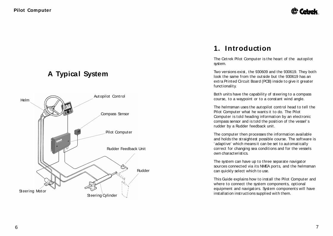
1. IntroductionThe Cetrek Pilot Computer is the heart of the autopilotsystem.
Two versions exist, the 930609 and the 930619. They bothlook the same from the outside but the 930619 has anextra Printed Circuit Board (PCB) inside to give it greaterfunctionality.
Both units have the capability of steering to a compasscourse, to a waypoint or to a constant wind angle.
The helmsman uses the autopilot control head to tell thePilot Computer what he wants it to do. The PilotComputer is told heading information by an electroniccompass sensor and is told the position of the vessel’srudder by a Rudder feedback unit.
The computer then processes the information availableand holds the straightest possible course. The software is‘adaptive’ which means it can be set to automaticallycorrect for changing sea conditions and for the vesselsown characteristics.
The system can have up to three separate navigatorsources connected via its NMEA ports, and the helmsmancan quickly select which to use.
This Guide explains how to install the Pilot Computer andwhere to connect the system components, optionalequipment and navigators. System components will haveinstallation instructions supplied with them.
Autopilot Control
Compass Sensor
Pilot Computer
Rudder Feedback Unit
Rudder
Steering CylinderSteering Motor
Helm
A Typical System

9
Pilot Computer
8
1.1 Before you start installationBefore commencing the installation of the new systemplease carry out the following checks:
• that the items delivered are correct and undamaged ?
• that the drive unit is the correct voltage for the vessel ?
• if you are using a hydraulic pump, that you have thecorrect size fittings available to connect the pump ?
• that you have the correct type of hydraulic fluid to topup the steering system once the pump is installed ?
• that you have power cables of a suitable gauge tosupply power to the system?
• that you have Circuit Breakers to suit the system?
If you find an error please contact the supplier of theproduct immediately.
Before the drilling or cutting of any holes takes place,please consider the exact location and cable routing thatis required for each unit. Please read this installationdocument and any installation information supplied withthe individual units before you install the system.
All exposed moving parts must be sufficientlyguarded to prevent accidental damage to personsor clothing.
InstallationStep 1
930609 versionhas one PCB
930619 version hasthis additional PCB
The Pilot Computerwith its cover off.
An Expansion Kit to convert a 930609 to a 930619 is part number 930298.

11
Pilot Computer
10
If it is necessary to extend the Drive Unit cables, theyshould be extended using a heavy duty cable, by theshortest possible route, to avoid unnecessary power loss.
All DC supply cables should be kept as short as possible,and should be taken from the battery via a switch/fuse orcircuit breakers of suitable rating for the system beinginstalled.
Two separately switched and fused power supplies mustbe connected to the Pilot Computer. The first is for thelight duty primary supply for the electronic control system.The second is for the heavy duty supply for the drive unit.
Avoid running power or motor supply cables, together orin the same conduit, with control and compass cables.This helps reduce the risk of interference.
It is good practice to cleat all cables to fixed points (notgreater than 0.5 m (18") apart) and where cables passthrough bulkheads, protect the cable with a suitablegrommet or sleeve.
If the vessel has a “clean” earthing system (i.e. using adyna plate or similar system) then the case of the PilotComputer may be connected to it using a heavy dutycable or copper strip, this will usually improve RFIrejection.If it does not, leave the the case isolated.
The negative of the battery system is not normallya clean earth and the case of the Pilot Computershould not under any circumstances be connectedto it.
Just in case Why not record the serial numbers of the units on page 59while they are easy to get at.
1.2 Suggested Installation StepsWe suggest that the following procedure will allow you toinstall the system encountering the least problems.
Read the documentation, then select the best positionsfor the units, then install the units in the following order:
Pilot Computer page 12
Autopilot Control, route the cable to thePilot Computer and connect it page 14
Compass Sensor, route the cable to thePilot Computer and connect it page 20
Rudder Feedback Unit , route the cable to thePilot Computer and connect it page 22
Drive Unit, route the cable to thePilot Computer and connect it page 24
Route the power supplies to thePilot Computer and connect them page 26
Optional Equipment, route the cables to thePilot Computer and connect them page 28
Carry out dockside settings and sea trials - see theUser’s Guide for the Autopilot Control being used.
1.3 Wiring Hints and Tips
Ensure that the Power is disconnected, beforeremoving the Component Cover.
All cable runs should be kept as clear as possible fromother cables carrying RF (radio frequency), pulsed signalsor heavy currents (such as winches etc.). At least 3 ft.clearance is advised. Take particular care to ensure themaximum clearance from radio transmitting aerials.
If it is necessary to extend any of the cables, the sametype of cable must be used. Screened cables must bebonded at the Pilot Computer as shown on page 13.
1
23
4
5
6
7
8
Installation Step

13
Pilot Computer
12
2 Cable Tiesper ‘Tongue’
Recommended
Fixing ‘Tongues’
Fixing ‘Tongue’Screen
Cable Ties
OuterInsulation
2.1 Removing the Cover¼ turn the fasteners to release the cover, then lift it off.
2.2 Fixing CablesThis shows the recommended method of attaching cablesand their screens.
Screened cables must be bonded by stripping the outerinsulation then clamping the screen to a fixing ‘tongue’.
The 775 Cable Screen MUST be isolated from thefixing ‘tongue’, as the screen is connected to pin 1.
2 ‘Keyhole’ mountingslots each side.
2. Installing the PilotComputerThis is the heart of the autopilot system and all unitsconnect to it.
Mount this on a vertical bulkhead in a dry, accessibleposition. Keep the heavy duty cable runs to the batteryand the drive unit as short as possible, but at least 1M (3ft)long. Short runs are particularly important on sailingvessels where battery life is an important factor.
If mounted in an engine room, ensure the area is wellventilated to avoid high ambient temperatures andabnormal condensation levels.
This equipment is capable of generating sparksand should therefore be mounted away from anyarea where there is risk of inflammable gases ormaterials.
InstallationStep 2

15
Pilot Computer
14
BlackOrangeYellow
RedViolet
Brown
PL10GNDTX dataTX LatchLDSS+RX dataTX clock
654321
Connect the cablescreen to the fixing
‘tongue’(as shown on page 13).
BulkheadConnector
cable 510545
3.1 Connecting a 715 or 730Autopilot ControlSee the User’s Guide for installation advice.
• 715 or 730s cannot be used with 700s.
3. Connecting the AutopilotControlSelect the section for the Autopilot Control to be fitted toyour system. Refer to the Autopilot Control’s own User’sGuide for full installation advice.
InstallationStep 3
cable 510529
cable 510529
BulkheadConnector
1. Remove theplug fromthe firstcable.
2. Then connectthe wires intothe plug ofthe secondcable.The wires arethe samecolour, seebelow.
3. Insert the pluginto PL10.
Connecting two 715s, two 730s or a 715 with a730 Autopilot Control• Two 715’s, two 730’s or a 730 and a 715 must be
wired in parallel (into the same plug).
cable 510545
cable510529

17
Pilot Computer
16
Connect the cable screen to the fixing‘tongue’ (as shown on page 13).
cable 510529
GNDTX dataRX dataLDSS+OFFON
BrownViolet
RedYellow
OrangeBlack
PL14ONOFFLDSS+RX dataTX dataGND
BlackOrangeYellow
RedViolet
Brown
123456
654321
PL15
3.3 Connecting a 725 or 750Autopilot ControlSee the User’s Guide for installation advice.Connect the Autopilot Control to PL14, use PL15 if it is asecond station.
The 700 does not have an On/Off switch, therefore:• systems with only 700s, move J7 to the ‘Auto Power On’
position.• If the 700 is used as a second station with an Autopilot
Control that has an on/off switch, J7 must not bemoved, the other Autopilot Control’s must be used toturn the autopilot on or off.
• Two 700s can be wired in parallel (into the same plug).• A 700 cannot be used with a 715 or 730.
BlackOrangeYellow
RedViolet
Brown
GNDTX dataTX LatchLDSS+RX dataTX clock
PL10654321
Connect the cable screen to the fixing‘tongue’ (as shown on page 13).
cable 510529
3.2 Connecting a 700 Autopilot ControlSee the 930700 User’s Guide for installation advice.
cable 510529
J7 positionfor 700 only
systems

19
Pilot Computer
18
Ô
Connect the NMEA cable screen to thefixing ‘tongue’ (as shown on page 13).
4321
GND (-)OUTPUT (+)
PL16
NMEA cable 510552
GreenWhite
To display instrument data (such as Speed or Depth) onyour 775, you will need an NMEA connection to theCartridge Reader. This can come from the instrumentsdirect, or preferably via the PL16 of the Pilot Computer.
The Pilot Computer combines NMEA information from its 3NMEA Inputs and its Instrument Input (PL12) into oneNMEA Output (NMEA3, PL16).
To feed this output to the 775, connect pins 3 and 4 ofPL16 to the NMEA Input of the Cartridge Reader.
Set the Navigator Input to “Internal”, in the ChartpilotsInstallation Setting Sub-menu.
cable 510551
Optional Instruments
654321
PL14
GNDTX dataRX dataLDSS+OFFON
ScreenWhiteYellow
PinkBlue
Green
3.4 Connecting a 775 ChartpilotSee the 930775 User’s Guide for installation advice.
Connect to PL14 (a second 775 connects to the773 cartridge reader via its LCD).
Set the Navigator Input to “External”, in the Chartpilot’sInstallation Setting Sub-menu.
In this instance the cable screen MUST be isolatedfrom the fixing ‘tongue’
The screen is connected to pin 1.
cable 510551
Ô
ScreenWhiteYellow
RedGrey
Green
or

21
Pilot Computer
20
PL12Blue
WhiteBlack
IN+IN-OutGND
4321
PL10
RedLDSS+
Tx
Rx
S S +
0V
654321
Connect the cable screen to the fixing‘tongue’ (as shown on page 13).
4.1 Connecting a Pick-Off Coil SystemThe 930687 consists of a 587 Interface with a 593 Sensor.
See the units documentation for installation advice.
Connect the Interface to PL10 and to PL12. If there is anAutopilot Control connected to PL10, the red wire fromthe Pick-Off Coil interface should be wired into the sameconnector.
Sensor930593
Interface930687
Connect the cable screen to the fixing‘tongue’ (as shown on page 13).
4. Connecting a 580 CompassSee the units documentation for installation advice.Connect Compass Units to PL8.
InstallationStep 4
It is important to calibrate the 580 Compass Sensorbefore the autopilot is put into full use.
Please refer to the Autopilot Control’s User’s Guide fordetails of how to carry out this procedure, known as‘Automatic Deviation correction’.
PL8RedGreenBlueWhiteBlack
+ 8 VSineCosRef.GND
54321

23
Pilot Computer
22
If the Jumper needs to be repositioned:Disconnect the Power.
Set J1according to
the table.
Remove the thumb nutthen lift the ComponentCover up and left.
5.1 Position of the Jumper J1To allow for the wide range of Rudder Feedback Units, thesignal can be amplified or un-amplified, depending on theposition of J1
Refit the Component Cover on completion.
5. Connecting a RudderFeedback UnitSee the units documentation for installation advice.
Connect the Rudder Feedback Unit to PL13.
Connect the cable screento the fixing ‘tongue’
(as shown on page 13).
WhiteRedBlack
Signal+ 5 VGND
123
PL13
A 930801 has extra wires for connecting to older systems.These are not used and should be isolated.
InstallationStep 5
715 and 730 systems do not require J1 to be movedfrom the factory default position. You may selectamplified or non-amplified signals from the AutopilotControl. Refer to the User’s Guide.
Un-amplifiedfor
930807930837930801930538
Linear drivewith RFU930130930132930180930182
Amplified(factory default)
for930809930877
Table for J1

25
Pilot Computer
24
SolenoidValve 1
SolenoidValve 2
Diode 1N5401or equivalentDiode 1N5401or equivalent
Shipssupplynegative (-)
Move J3 to this‘Spool Valve’ Position
PL6+ ve - ve
21
5 Amp Fuse
6.1 Connecting Solenoid Operated SpoolValvesIf solenoid operated spool valves need controlling, connectthem to PL2 and move the Jumper J3 to the right.
Diodes are required across the solenoids, sometimes theyare built in, if not, fit 1N5401’s or equivalents, as close aspossible to the solenoids.
It is recommended that 5 Amp Fuses are fitted in the DriveLines to the Spool Valves.
The solenoids are wired ‘common ground’, ensureall other equipment wired to the solenoids is alsocommon ground, otherwise damage may occur.
6.2 Dual Rate Output
When the autopilot applies more than 10º of rudder, PL6outputs a signal. This can be up to 5 amps at the heavyduty supply voltage. It is intended for hydraulic systemsconfigured for dual rate operation.
+--
Connect any cable screens to the fixing‘tongue’ (as shown on page 13).
6. Connecting a Drive UnitSee the documentation that came with your drive unit forinstallation advice.
InstallationStep 6
Two wires from the drive unit motor connect to PL2.Polarity is not important at this stage.
If the cables need to be extended, ensure that the correctcable rating is used.
The table on page 26, for the heavy duty supply, can beused as a guide in case of uncertainty
If a clutch solenoid needs controlling, connect it to PL1, asshown below.

27
Pilot Computer
26
If the vessel has a “clean” earthing system (i.e. using a dynaplate or similar system) then the case of the Pilot Computermay be connected to it using a heavy duty cable or copperstrip, this will usually improve RFI rejection.
If no such system is available, leave the Pilot Computerisolated.
The negative of the battery system is not normally aclean earth and the case of the Pilot Computer shouldnot under any circumstances be connected to it.
The power supply cables should not be used to supplyboth the autopilot and other electronic equipment asswitching transients can be very troublesome and thispractice can cause RF interference.
+--PL2=Heavy Duty Supply
fused to suit Drive Unit
+--
PL5=Light Duty Supplyfused at 5 Amp.
Copper Cable If 2 Core If 1 Core CableArea Type Rated at, Rated at, Gauge
Up to 10 metres =2.5mm² 50/0.25mm 20A 30A 14AWGUp to 15 metres =4.0mm² 56/0.3mm 27A 40A 12AWGUp to 20 metres =6.0mm² 84/0.3mm 35A 53A 10AWG
Maximum system performance and minimum cable losses are ensuredby using a cable size bigger than the minimum recommended.
7. Connecting Power to thePilot ComputerWire the power to the 609/619 from the ships electricaldistribution box circuit breakers, or via switches andanti-surge fuses.
Two separate cables need to be used, one for the heavyduty and one for the light duty, even though on a lowpower system they may come from the same source.
InstallationStep 7
RECOMMENDED MINIMUM CABLE SIZE for the HEAVY DUTY SUPPLY
It is important that the Heavy Duty Supply cables are of agreater current rating than the Drive Unit motor.
For example, if your motor is rated at 10 amps, the cablerun is 4 metres (12 feet), use at least 20 amp 2 core cableor 30 amp single core cable.

29
Pilot Computer
28
Connect the cable screens to the fixing ‘tongue’(as shown on page 13).
8. Connecting OptionalEquipment
8.1 Connecting NMEA devices to a 609The 609 version has one NMEA input/output port, NMEA1(PL11).
An LED adjacent to the NMEA connector will flash aboutonce a second as input dyata is detected. If it is on most ofthe time and flickering, the input signal polarity isprobably wrong.
PL12 can be used as an input for Instrument data.
NMEA output is from pins 3 and 4 of PL11.
All NMEA sentances supported are listed on Page 48.
Ensure that you observe signal polarity.
InstallationStep 8
PL12IN+IN-OutGND
4321
Connecting a Navigator or GPSThere are three basic configurations of navigator output:
1. Serial data type 1 :Signal +ve (0183) connect to pin 1 of NMEA1 (PL11).Signal -ve (or Return) connect to Pin 2 of NMEA1.
2. Serial data type 2 :Signal +ve (0183) connect to pin 1 of NMEA1 (PL11).Ground connect to Pin 2 of NMEA1.
3. RS 422 based output :Signal TX- connect to pin 1 of NMEA1 (PL11).Signal TX+ connect to Pin 2 of NMEA1.Use a seperate 2 wire shielded cable for these twoconnections.
Set the output format of all navigators to NMEA 0183,preferably version 2, but version 1.5 will work.
If the output sentences can be selected, RMB, RMC or APBare suitable options.
Connecting other NMEA DevicesNMEA instrument inputs, such as a Windvane or Speedand Depth Instruments, connect to pins 1 and 2 ofNMEA1 (PL11), or if that is used by a navigator, PL12 pins 3 &4 can be used. PL12 cannot read navigator messages.
PL11IN+IN-
OUTGND
1234
31
Pilot Computer
30
Connecting a Navigator or GPSConnect the navigator or GPS antenna to pins 1 and 2 ofMNEA1 (PL11). If there is a second navigator, connect it toNMEA2 (PL17), a third navigator would connect to NMEA3(PL16).
There are three basic configurations of navigator output:
1. Serial data type 1 :Signal +ve (0183) connect to pin 1 of NMEA1 (PL11).Signal -ve (or Return) connect to Pin 2 of NMEA1.
2. Serial data type 2 :Signal +ve (0183) connect to pin 1 of NMEA1 (PL11).Ground connect to Pin 2 of NMEA1.
3. RS 422 based outputs :Signal TX- connect to pin 1 of NMEA1 (PL11).Signal TX+ connect to Pin 2 of NMEA1.Use a seperate 2 wire shielded cable for these twoconnections.
Set the output format of all navigators to NMEA 0183,preferably version 2, but version 1.5 will work.
If the output sentences can be selected, RMB, RMC or APBare suitable options.
Connecting other NMEA DevicesNMEA instrument inputs, such as a Windvane or Speedand Depth Instruments, connect to pins 1 and 2 of anyNMEA port not used by a navigator.PL12 pins 3 & 4 can be used for instrument data if there arenot sufficient NMEA ports. PL12 cannot read navigatormessages.
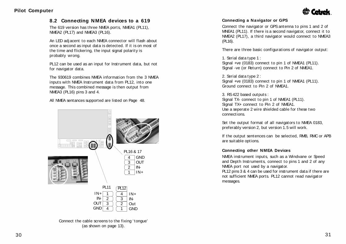
8.2 Connecting NMEA devices to a 619The 619 version has three NMEA ports, NMEA1 (PL11),NMEA2 (PL17) and NMEA3 (PL16).
An LED adjacent to each NMEA connector will flash aboutonce a second as input data is detected. If it is on most ofthe time and flickering, the input signal polarity isprobably wrong.
PL12 can be used as an input for Instrument data, but notfor navigator data.
The 930619 combines NMEA information from the 3 NMEAinputs with NMEA Instrument data from PL12, into onemessage. This combined message is then output fromNMEA3 (PL16) pins 3 and 4.
All NMEA sentances supported are listed on Page 48.
Connect the cable screens to the fixing ‘tongue’(as shown on page 13).
GNDOUTIN-IN+
PL16 & 174321
PL12IN+IN-OutGND
4321
PL11IN+IN-
OUTGND
1234

33
Pilot Computer
32
8.5 Gyro InputGyro interfaces that output NMEA data can be connectedas explained in section 8.1 or 8.2.
Alternatively the 930619 Pilot Computer can accept gyrostepper signals (1:360, 180 or 90) on user port PL18, via aplug-in adapter 930525.See the documentation supplied with the adapter forinstallation advice.
8.3 Connecting a Digital CompassThe Pilot Computer can accept heading data from anexternal compass connected to PL12 pins 3 & 4.
It will accept the following NMEA heading messages:
HDM, HDG, HDT, VHW
The repetition rate of the sentance needs to be betterthan 5 per second. The port will accept Cetrek HeadingData from a 930577 Compass Sensor or Pick-Off CoilSystem (see pages 21 and 40).
8.4 Connecting a 581 Rate SensorThe 930581 Rate Sensor connects to PL19.930609 Pilot Computers need adaptor kit 930534.
See the documentation supplied with the equipment forinstallation advice.
The 581 will only work inconjunction with a 930580compass.
Connect the cable screen tothe fixing ‘tongue’
(as shown on page 13).
PL12IN+IN-OutGND
4321
930525Interface
PCB
Connect the cablescreen to the fixing
‘tongue’ (as shown onpage 13).
PL18Common (+ve)8
7654321
Step 1
Step 2
Step 3
To change direction, swop any two step lines.
PL19BlackWhiteRed
AGNDSIG+ 5 V
54321
35
Pilot Computer
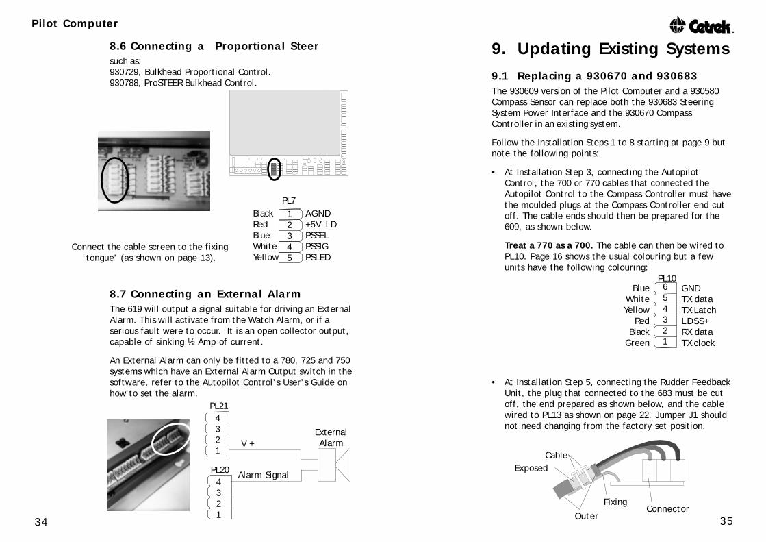
34 Outer
Cable
ConnectorFixing
Exposed
BlueWhiteYellow
RedBlack
Green
GNDTX dataTX LatchLDSS+RX dataTX clock
PL10654321
9. Updating Existing Systems
9.1 Replacing a 930670 and 930683The 930609 version of the Pilot Computer and a 930580Compass Sensor can replace both the 930683 SteeringSystem Power Interface and the 930670 CompassController in an existing system.
Follow the Installation Steps 1 to 8 starting at page 9 butnote the following points:
• At Installation Step 3, connecting the AutopilotControl, the 700 or 770 cables that connected theAutopilot Control to the Compass Controller must havethe moulded plugs at the Compass Controller end cutoff. The cable ends should then be prepared for the609, as shown below.
Treat a 770 as a 700. The cable can then be wired toPL10. Page 16 shows the usual colouring but a fewunits have the following colouring:
• At Installation Step 5, connecting the Rudder FeedbackUnit, the plug that connected to the 683 must be cutoff, the end prepared as shown below, and the cablewired to PL13 as shown on page 22. Jumper J1 shouldnot need changing from the factory set position.
Alarm Signal
PL21
ExternalAlarmV +
4321
PL204321
8.6 Connecting a Proportional Steersuch as:930729, Bulkhead Proportional Control.930788, ProSTEER Bulkhead Control.
Connect the cable screen to the fixing‘tongue’ (as shown on page 13).
PL7AGND+5V LDPSSELPSSIGPSLED
BlackRedBlueWhiteYellow
12345
8.7 Connecting an External AlarmThe 619 will output a signal suitable for driving an ExternalAlarm. This will activate from the Watch Alarm, or if aserious fault were to occur. It is an open collector output,capable of sinking ½ Amp of current.
An External Alarm can only be fitted to a 780, 725 and 750systems which have an External Alarm Output switch in thesoftware, refer to the Autopilot Control’s User’s Guide onhow to set the alarm.
37
Pilot Computer
36
Connect the cable screen to the fixing‘tongue’ (as shown on page 13).
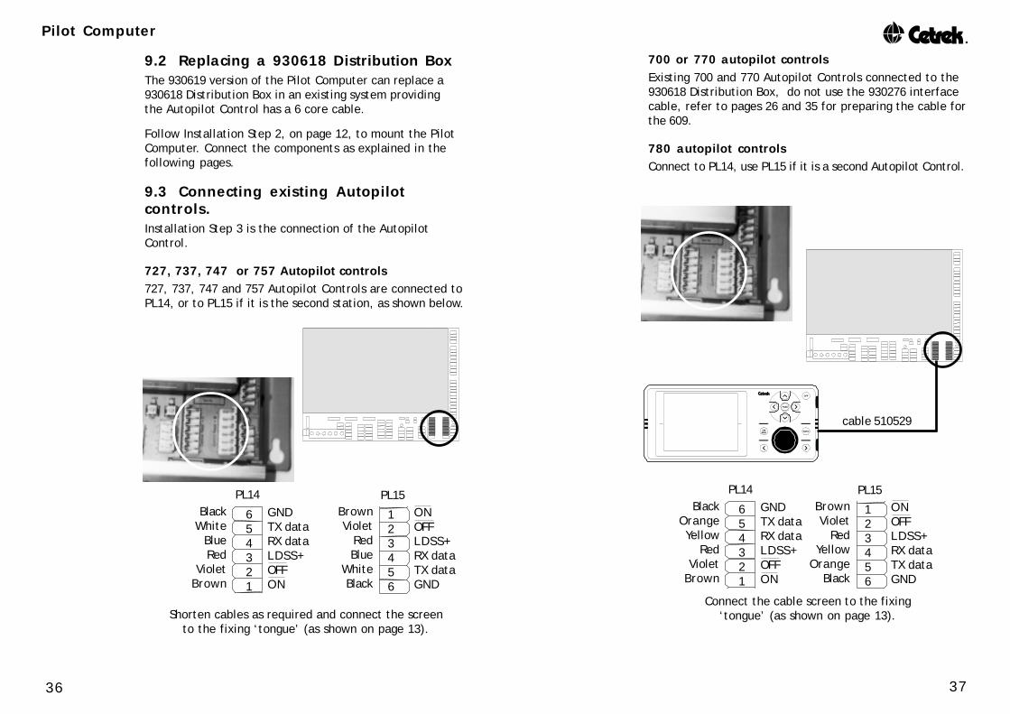
cable 510529
GNDTX dataRX dataLDSS+OFFON
BrownViolet
RedYellow
OrangeBlack
PL14ONOFFLDSS+RX dataTX dataGND
BlackOrangeYellow
RedViolet
Brown
123456
654321
PL15
Shorten cables as required and connect the screento the fixing ‘tongue’ (as shown on page 13).
GNDTX dataRX dataLDSS+OFFON
BrownViolet
RedBlue
WhiteBlack
PL14ONOFFLDSS+RX dataTX dataGND
BlackWhite
BlueRed
VioletBrown
123456
654321
PL15
9.2 Replacing a 930618 Distribution BoxThe 930619 version of the Pilot Computer can replace a930618 Distribution Box in an existing system providingthe Autopilot Control has a 6 core cable.
Follow Installation Step 2, on page 12, to mount the PilotComputer. Connect the components as explained in thefollowing pages.
9.3 Connecting existing Autopilotcontrols.Installation Step 3 is the connection of the AutopilotControl.
727, 737, 747 or 757 Autopilot controls727, 737, 747 and 757 Autopilot Controls are connected toPL14, or to PL15 if it is the second station, as shown below.
700 or 770 autopilot controlsExisting 700 and 770 Autopilot Controls connected to the930618 Distribution Box, do not use the 930276 interfacecable, refer to pages 26 and 35 for preparing the cable forthe 609.
780 autopilot controlsConnect to PL14, use PL15 if it is a second Autopilot Control.

39
Pilot Computer
38
Connect the NMEA cable screen to the fixing‘tongue’ (as shown on page 13).
Ô
Connect the GPS or other navigator toPL11 (NMEA in, pins 1 & 2).
Connect the NMEA output PL16pins 3 & 4 to both the 775 and
the 780 NMEA inputs.
Connectthe 775 to
PL14
Connect the 780to PL15
Ô
Connect the cablescreens to the fixing
‘tongue’(as shown on page 13).
Optional Instruments
4321
GND (-)OUT (+)
PL16
Ô
Connect the cable screens to the fixing‘tongue’ (as shown on page 13).
cable 510529
To display instrument data (such as Speed or Depth) onyour 780, you will need an NMEA connection. This cancome from the instruments direct, or preferably via thePilot Computer.
The Pilot Computer combines the NMEA information fromits 3 NMEA Inputs and PL12’s input. It combines this intoone NMEA message which it outputs from NMEA3 (PL16).
To feed this output to the 780, connect pins 3 and 4 ofPL16 to the NMEA Input of the 780.
775 with a 780 autopilot controlExisting 775 and 780 Autopilot Controls are connected asshown .
See the 930775 and 930780 User’s Guide for installation advice.
This is the preferred connection method.
The 775 cable screen MUST be isolated from thefixing ‘tongue’. The screen is connected to pin 1.
Ô

41
Pilot Computer
40
930572930576930577
PL12Blue
WhiteBlack
IN+IN-OutGND
4321
PL10
RedLDSS+
Tx
Rx
S S +
654321
Connect the cable screen to the fixing‘tongue’ (as shown on page 13).
9.4 Connecting an existing Compass
572, 576, 577, 682, 686 or 687Installation step 4, connecting the compass.
931682 consists of a 930582 Interface with a 930593 Sensor,931686 consists of a 930586 Interface with a 930593 Sensor.931687 consists of a 930587Interface with a 930593 Sensor.
Remove the connector and re-wire it as shown below.Failure to do so will cause serious damage to the sensor.
9.5 Connecting the existing RFUInstallation Step 5, connecting the Rudder Feedback Unit(RFU). If the existing 807 or 801 RFU is to be used, J1 willhave to be moved to the un-amplified position. Follow theinstructions on page 23.
9.6 Connecting the restFollow Installation Steps 6 and 7, from page 24 onwards,to connect the Drive Unit and Power to the PilotComputer.
When connecting Spool Valves, the 930609/619 iscommon negative and is different to the 930618,which is common positive. See page 25 for thecorrect setup.
Finally connect any optional equipment as explained in thefollowing pages.
931682931686931687
Link pins 1 and 3.

43
Pilot Computer
42
Connect thecable screento the fixing‘tongue’ (asshown onpage 13).
PL21
PL18GreenYellowBlue
87654321
Black
Red
DGND
LDSS+
4321
9.9 Connecting a 523 Gyro Synchro /Stepper InterfaceThe 930523 Gyro Synchro / Stepper Interface connects toPL18 and PL21 of a 930619. Interface 123318 is required,fitted into SK3 located under the Component Cover.
To fit the interface:Ensure that the Power to the Pilot Computer isdisconnected. Insert the Interface
Plug into SK3 on the930619 PCB
observing polarity
Remove the thumb nutthen lift the Component
Cover up and left.
Refit the Component Cover on completion
123318
PL9GND+ 5 VREMSWREMPREMSREMLED
BlackN/CGreenWhiteBlueN/C
123456
Connect the cable screen to the fixing‘tongue’ (as shown on page 13).
BlackYellowGreenWhiteBlueRed
797 706
9.7 Connecting a Jog Steer930705 Jog steer930706, ProJOG Control.930797, Portable Dodge & Course Control.
Do not fit more than one 705, 706 or 797 to thesame Pilot Computer.
9.8 Connecting a Proportional Steersuch as:930717, Portable Proportional Control.930787, Flush mount Proportional Control.connect to PL7. PL7
AGND+5V LDPSSELPSSIGPSLED
BlackRedBlueWhiteYellow
12345
GreenN/C
link to GreenWhiteBlack
N/C
705

45
Pilot Computer
44
Connect the cable screens to the fixing‘tongue’ (as shown on page 13).
9.11 Connecting a C-net COMPASS 930383See the documentation supplied with the equipment forinstallation advice.
To receive compass heading data from the Pilot Computerconnect the C-net COMPASS to either PL11, PL17 or PL16,but please note, only PL16 outputs the full navigatormessages.
Connect pin 3 OUT to NMEA Rx +Connect pin 4 GND to NMEA Rx -Set the Product Type on the C-net COMPASS to 4.
9.12 Connecting a 930319 Rudder AngleGauge.The 930319 Rudder Angle Gauge is an NMEA device.Connect it to PL16 (NMEA2) pins 1 & 2.
PL11
OUTGND
1234
PL16 & 174321
GNDOUT
Connect the cable screens to thefixing ‘tongue’ (as shown on page 13).
Ship’ssupply
-
Ship’ssupply
+
Tx &Rx
G N D
NMEARx
9.10 Connecting a C-power Compass Gaugesuch as:930460, C-power Digital Compass.930462, C-power Analogue Compass.
See the documentation supplied with the equipment forinstallation advice.
To receive compass heading data from the Pilot Computerconnect the C-power Compass to either PL11, PL17 or PL16.
Connect pin 3 OUT to NMEA RxConnect pin 4 GND to Tx & Rx GND
PL11
OUTGND
1234
GNDOUT
PL16 & 174321

47
Pilot Computer
46
10.‘On’, ‘Port’ and ‘Stbd’SwitchesOnce the basic installation is complete, the 3 switchesabove PL12 and PL13 can be used to check the installation.
The middle switch turns the Pilot Computer ON provided ithas power to it. An Autopilot Control does not need to bepresent. It will NOT turn the unit Off, the power must beisolated to do that.
Powering up with the Port button held down forat least five seconds, overrides the ruddersettings alarm. This allows the motor to be runbefore doing the Dockside settings rudder setup.
The other two switches activate the motor output todrive the rudder to port or starboard depending on themotor phasing.
These switches may be used as an initial check that themotor cables and linkages are correctly installed, or tohelp bleeding hydraulic systems.
Be sure that the rudder can move from hard-overto hard-over without damage. Rudder limits maynot have been set.

49
Pilot Computer
48
NMEA3 (PL16) Output Messages:HDM, RSA, VHW,plus (if the information is available)APA, APB, BOD, BWC, BWR, HDG, HDT, RMA, RMB, RMC,XTE, GGA, GLL, VTG, ZDA, DBT, DPT, MTW, MWV.
11.3 Default SettingsDefault settings (no Pilot uses all settings)
Compass Damping 0 (Auto Compass Damping)Dodge limit 10Motor Speed Control 100Nav Gain 5Power Steer Gain 5PWM ONResponse A (Adaptive) *RFU signal AMPLIFIEDRudder Deadband 3Rudder Limit 7 *Rudder Reduction Angle 0Transition Speed 0 (Off)Trim 4 *Turn Rate 20 *Waypoint Sequence AUTOWind Gain 1Boat Type (Hull Type) PLANING
Pilot ARudder Ratio 4 *Counter Rudder 1 *
725 and 750 pilots havetwo additional Pilot sets, B and C.The setting marked * above can be different in each set.
These are the default values that change when other boattypes are selected:
Pilot ADisplacementRudder Ratio 10Counter Rudder 4
Semi-displacementRudder Ratio 7Counter Rudder 3
SailboatRudder Ratio 10Counter Rudder 4
11.SpecificationsSupply Voltage: nominal 12/24V DC
maximum 32V DCminimum 10.5V DC
NMEA Voltage: Output 0 to +5V DCInput -15V to +15V DC
Maximum continuousdrive current: 26 Amp LimitStorage Temperature: -20 to +75ºCOperating Temperature: 0 to 55ºCWeight: 1.5 KgCompass Safe Distance: Grade 1 (1/4º) 1350 mm (53”)
Grade 1 (1º) 800 mm (32”)
Fuses - Automotive Type Blade Fuses
FS1 30 Amp Heavy Duty Ships Supply InputFS2 5 Amp Light Duty Ships InputFS3 5 Amp Dual Rate OutputFS4 5 Amp Clutch
11.1 NMEA 0183 Input Messages
NMEA 1, 2 & 3 Input Messages that can be read:Autopilot & Navigation: APA, APB, BOD, BWC, BWR, RMA,
RMB, RMC, XTE, VWR.Navigation: GGA, GLL, VTG, ZDA.Instrumentation: DBT, DPT, MTW, MWV, VHW,
VLW,WDC.
PL12 Input Instrument Messages that can be read:Instrumentation: HDM, HDG, HDT, VHW, DBT, DPT,
MTW, MWV,VTG,RMA,RMC,VWR,WDC.
11.2 NMEA 0183 Output Messages
NMEA 1(PL11) Output Messages: 100ms repetition rate.HDM, RSA, VHW (also Cetrek proprietary message $PCETP).
NMEA 2 (PL17) Output Messages: 100ms repetition rate.HDM, RSA, VHW.

51
Pilot Computer
50
13.Changing EpromsThe software is stored in the EPROM IC3.
EPROMS are Static Sensitive Devices. Take suitableprecautions when handling them.Fitting the EPROM reversed will cause permanentdamage to the new EPROM.
• Disconnect the Power.
• Release the quarter turn fasteners and remove the cover.
• Release the retaining screw, then remove theComponent Cover.
• IC3 is located in thecentre of the PCB.Carefully prise theEPROM from its socketwith a smallscrewdriver. Be surethat you do notdamage any tracksunder the chip.• Align the indent onthe new EPROM withthe indent marked on
the PCB. Check that all pins are over the individual ICsockets, then push down firmly in the centre of theEPROM. Ensure no pins are bent or have failed toenter the socket.
• Re-assemble the covers.
• Restore the Power supplies
• Turn the autopilot on. If system fault ‘SFLT 002’ isdisplayed, switch the Autopilot Control off and onagain, this should clear the condition (this must bedone at the Autopilot Control, not the circuit breaker).
• If the system will not stay powered up when theStandby key is pressed, it is almost certain that theEPROM has not been fitted correctly. Check and retest.
• If the display remains blank but the system has power,then check the EPROM is correctly fitted.
J1. Selectsamplified ornon-amplifiedRFU signal.See page 23for table ofuse.
J2 should always beset to ‘Eprom’.
J3. PWM or Spool valve. Only moveto ‘Spool Valve’ if driving solenoidoperated spool valves.Automatically turns the PWM off.
J4. Test Mode for factoryuse only. Fitting this linkwill seriously damage yourdrive system.
J8. Shouldalways beset to‘Fixed’.
J7. Move to ‘Autopower on’ for
systems with only700 Control
Heads.
12.Jumpers and LinksSummaryDisconnect the Power, before removing the ComponentCover to adjust the Jumpers and Links.

53
Pilot Computer
52
15.System FaultsThe System faults are identified by numbers as indicated below.For safety reasons, faults with a number greater than 128 willresult in the autopilot automatically switching to Standby(manual) mode.
002002002002002 NOVRAM CHECKSUM ERROR• This fault may indicate that the Autopilot’s stored parametersare no longer valid, these should be checked before further use.
007007007007007 COMPASS SIGNAL ERROR• Sine or Cosine voltage levels are too high.Resite the compass.
008008008008008 COMPASS SIGNAL ERROR• Sine or Cosine voltage levels are too low.Resite the compass.
036036036036036 EXTERNAL COMPASS MESSAGE FAULT
• The compass message has not been received correctly by thePilot Computer.If this occurs repeatedly then the compass should be repaired.
065065065065065 PORT MESSAGE OVERRUN ERROR• The messages received by the Pilot Computer for the AutopilotControl is longer than expected.It could be caused by excess electrical noise interfering with thedata cables of the Autopilot Control or by a loose 619 interfacePCB (100285).
066066066066066 PORT READ CHECKSUM ERROR• The messages received by the Pilot Computer for the AutopilotControl is longer than expected.It could be caused by excess electrical noise interfering with thedata cables of the Autopilot Control.
070070070070070 PL14 TIMEOUT• The alarm will occur if the Autopilot Control connected toPL14 in the Pilot Computer is incorrectly selected or if a controlunit fails to respond. Check the wiring to the plug.
071071071071071 PL15 TIMEOUT• The alarm will occur if the Autopilot Control connected toPL15 in the Pilot Computer is incorrectly selected or if a controlunit fails to respond. Check the wiring to the plug.
14.System MessagesIf your autopilot detects a problem with the system it will displaya warning on the LCD. For safety, a very serious problem willalso turn the autopilot to Standby Mode (Manual Control). Hereare the messages that we hope you will never see, along withsome explanations and some tips on what to do before you callyour Cetrek dealer.
System AlarmsSystem AlarmsSystem AlarmsSystem AlarmsSystem Alarms
LOW BATTERY The battery voltage is low.• Clear the alarm by pressing any key except the OFF key. Oncecleared the alarm will not trigger again until the autopilot hasbeen turned off and back on again. If the voltage drops too low,autopilot operation may be impaired. Check the vessel’scharging system.
NAVIGATOR This will be shown if any of the following occur:ALARM
• The autopilot has received no Navigator Data• The autopilot has received an error code from the Navigator• The autopilot has received more Navigator Data than itexpected or• The autopilot has “timed out” because it has not receivedexpected Navigator Data within a predetermined length of time.
Make the following checks:
• That the Navigator is turned on.• That the Data output format from the Navigator is the same asthe autopilot is set to receive (see Users Guide).• That NAV is selected correctly.• On the PCB inside the Pilot Computer there are LED’s besideeach NAV port (PL11, 16 & 17). The LED for each port will flashif data is being received by that port.• Check the Navigator for bad reception or faulty equipment.• Check the data output from the Navigator.
WIND ALARM The autopilot has “timed out” after not receiving expected WindInstrument Data.• Check the Data output from the Wind instrument.

55
Pilot Computer
54
198198198198198 RUDDER FEEDBACK FAULT• This may be caused by a fault in the Rudder Feedback Unit,wiring, excessive travel on the Rudder Feedback Arm or the linkJ1 (or software setting in 715 or 730) is set incorrectly.Check that the Rudder Feedback Unit has been correctlyinstalled.
200200200200200 MOTOR PHASING CHECK• This indicates that the rudder setting data is wrong. Repeat therudder setting routine detailed in the control head User’s Guide.
224224224224224 RUDDER DRIVE FAULT• The Pilot computer has sent a drive command to the drive unitbut the Rudder Feedback Unit has not detected a change in therudder position.
Check that the Rudder Feedback has not become disconnectedfrom the Rudder Arm, also check that the steering system,especially the motor, is operating the rudder gear correctly.
Ensure that the drive unit cables have not become disconnectedor loose.
Warning messages 128 and above are accompaniedby audible (if the unit has one) and visual alarms,and the autopilot will have switched to standby(manual) mode.
130130130130130 STACK OVERFLOW• Indicates that the software has crashed. This may be due toexcessive electrical noise near the Pilot Computer. Remove anysources of electrical noise then power OFF and back ON againto clear the fault. If the problem persists, consult your localCetrek dealer or distributor.
131131131131131 700 CONTROL HEAD ALARM.• Indicates that data from the 700 Autopilot Control is notpresent. Check the cable and connections.
134134134134134 715-730 CONTROL HEAD ALARM.• Indicates that data from the 715 or 730 Autopilot Control isnot present. Check the cable and connections.
165165165165165 COMPASS TIMEOUT• The Pilot Computer is not receiving heading information fromthe compass. Check the wiring. If a 580 Compass Sensor isconnected, check PL8, pins 2, 3 and 4. Their voltage should be2.5V ±1.5V, if they are not, the 580 Compass is faulty.This fault can be caused by a strong magnetic field close to thecompass sensor.
167167167167167 EXTERNAL DIGITAL COMPASS ALARM• The repetition rate of the NMEA input to the 619 from thecompass is too slow (>200ms).
176176176176176 RATE GYRO ALARM• Indicates that the data signal from the optional Rate Gyro is nolonger present (PL19 pin4 is at 5V). PL19 pin4 should be at anominal 2.5V when data is present.
192192192192192 GYRO STEPPER ALARM• Indicates that the data signals from the Gyro Stepper arefaulty, all ‘high’ or all ‘low’.

57
Pilot Computer
56
The Fail Safe Watchdog is causing system power down. A faulthas been detected on the Pilot Computer PCB. Remove the topcover and component cover from the Pilot Computer. Visuallycheck that the socketed IC3 Eprom is installed securely. Checkfor any loose material that may cause shorts.
If new software has just been fitted, check the IC legs. Damagedlegs will probably mean a damaged eprom.
The heavy duty supply and motor output cables are swappedover. Switch off immediately.
3. The displayworksmomentarilythen blanks andthe systempowers down.
See 1 and 2 above.
This could occur if RF energy is being injected into the powercables or by radiation injection into the pilot system componentsat very high levels. The autopilot has been exhaustively tested towithstand RF injection and radiation at levels far above thoseconsidered safe to personnel. Antenna mismatch yielding highstanding wave ratio (SWR) can cause dangerous conditions andin the interest of operator safety the radio installation should beinspected immediately.
A more normal problem to occur is that a Radio transmitter, orother high current unit, is being supplied from the same batteryas the autopilot. When the device is operated, it may be causingthe battery voltage to drop below that required to maintain theautopilot operation. Once power loss has occurred, the fail-safewatchdog has been designed to power down the system
4. Systempowers downfor no apparentreason andcannot berestarted
5. System powersdown when radioTransmitter orother RF device iskeyed; or when adevice needingcurrent isoperated (electricwindlass, etc.)
2. The motordrives hard overwhen power isapplied at thebreaker, withoutswitching thepilot on.
16.Troubleshooting GuideAfter installing the system according to this manual itshould work faultlessly. In the unlikely event of a faultoccurring, here are some notes that might get you out oftrouble.
General 1. Ensure all supplies are turned off before connecting orPrinciples & disconnecting wiring. Certain components will beCautions seriously damaged if inadvertently shorted out.
Damage caused in this manner is not covered bywarranty.
2. When first installing or when changing the wiringalways double check the colour coding beforeswitching on the power.
3. Check all wiring is correctly connected according tosteps 21-8.
4. Do not use a simple voltmeter to attempt to checkpowered up digital logic lines or signal lines.
5. Ensure that all cable screens are properly earthed.
6. Check the fuses and replace blown ones with directequivalents. Most units have one internal fuse, thePilot Computer has 4.
7. Take suitable precautions when handling PCB’s withStatic Sensitive Devices.
8. Read the ‘Wiring hints and tips’ advice on page 10.
Symptom Possible cause and remedy.
Check the breaker and both heavy and light duty power suppliesto the Pilot Computer.In the Pilot Computer:Check Fuses F1 and F2. Check the supplies from the PilotComputer to the Control head.For control heads connected to PL14 or PL15, check that pin 1,(normally 4 to 5V) changes to 0V when you try to turn theautopilot on, if not, then suspect a fault in the Pilot Computer.Check that pin 2 is normally 0V and changes to +5V when youtry to turn the autopilot on. If this is not so then a fault with thePilot Computer PCB is likely.
1. The systemwill not powerup.
59
Pilot Computer
58
Motor cable or supply cable too small.Motor faulty. Check brushes etc.On hydraulic systems check hydraulic fluid level. On mechanicalsystems check that the Clutch output and Motor Clutch areworking.
Indicates a rudder phasing or motor phasing error.Check that J1 is set correct and not loose.Check that the Rudder Feedback Unit arm has not becomedisconnected.Carry out the rudder setting procedure again.
11. Motordrives hardover whenautopilot isengaged
10. Motordrives bothways but lackspower.
If You Need Assistance
If you do ever need to contact your Cetrek Dealer orDistributor, it would save time if you could make a note ofthe following details for them for all of the units in yoursystem:
• Model Numbers:
• Serial Numbers:
• Software Version Numbers:
• A description of the failure.
automatically. This would be particularly noticeable if the batteryhad a bad cell or corroded connections. It is recommended thatwhere possible the autopilot is supplied with power from adifferent battery to the other auxiliary requirements.
This may happen very occasionally due to a momentary loss ofsynchronization during power up. The self test software reportsall errors of this type to help anticipate potential problems.Unless this happens repeatedly it is of little concern.
Check the heavy duty supply to the Pilot Computer.In the Pilot Computer:Check fuse F1.
If you suspect a faulty motor, test it by powering the motordirectly from a suitable battery.
Normally this can be traced to a wiring error. System faultmessages are explained and action to be taken is given, in“System Messages” on page 52.
7. The autopilotpowers up butdisplays aSystem Faultwhich cannot bereset.
8. Autopilotdisplays ‘AUTO’but motor doesnot drive
Centre the helm and retry to ensure you are inside the electroniclimits.Check that J1 is securely fitted.Check the RFU cable and its connections.Check the RFU or its linkage has not come loose.Otherwise suspect a drive FET or logic failure on the PilotComputer PCB.
Low battery voltage.
9. Motor drivesone way only
6. The autopilotpowers up butdisplays SystemFaults which canbe reset and donot immediatelyrecur

61
Pilot Computer
60
designated is warranted as set forth in paragraph V herein.
iii. There is no warranty and the warrantor shall not be held liable for any damagesincurred as a result of a malfunction of any part of the warrantor’s products, if saiddamages incur during or as a result of the autopilot being left unattended by theoperator. The warranty shall not be liable for any damage arising from collisions withother vessels or objects. The autopilot product, including parts thereof, is designed toassist the operator or the persons on watch to navigate accurately by maintaining anaverage course selected by the person on watch. The warrantor’s products are notdesigned to, and do not, replace the persons on watch. Due to the potential of a collisionwith an object in the vessel’s path or of an electrical, mechanical or hydraulic malfunctionof the parts of the autopilot or the associated equipment of the vessel, the energisedpilot should never be left unattended when the vessel is moving.
iv. The sole remedy available to the purchaser if there is a defect in material orworkmanship of the equipment is as set out in paragraph V.
v. Save in respect of loss of life and personal injury, which liability can not be excludedby law, the warrantor shall have no liability for incidental or consequential damages ofany kind.
vi. This warranty shall not cover defects or damage arising as a result of the faultyworkmanship of any distributor, agent of the seller or dealer in the goods, or otherperson not being the seller or it’s employee in respect of the installation of the goods.
vii. The warrantor hereby notifies the purchaser purchasing as a consumer, that hisstatutory rights given under the Sales of Goods Act 1979 and Supply of Goods andServices Act 1982 are not affected by this warranty.
VIII.The purchaser’s obligations in the event of defect are to:
i. Prepare a written detailed statement to the warrantor’s factory at the aboveindicated address.
ii. Deliver the written statement to the warrantor’s factory at the above indicatedaddress.
iii. Deliver or arrange for the delivery of the equipment to the warrantor’s factory.
iv. Arrange for the return of the equipment from the warrantor to the purchaser byeither agreeing to pick up the equipment at the warrantor’s factory or by depositing withthe warrantor sufficient funds to pay to have the equipment delivered to the purchaserby means of commercial transportation other than standard freight services (UPSground).
IX. The purchaser hereby agrees that he has read and understands that the above warrantysets forth the exclusive warranty for this equipment.
Limited Warranty applying to all products of Cetrek Ltd.
I. The Warrantor is: Cetrek Ltd. Through their Dealership.
II. This warranty shall extend only to the original purchaser of the equipment.
III. This Warranty applies to all equipment manufactured by, or bearing the name plaque of,Cetrek Ltd., and the warrantor warrants all such equipment to be free from defects inworkmanship or material under normal use and service.
IV. This Warranty is in effect for a period of 24 months from date of invoice from a dulyauthorised Cetrek distributor.
V. i. If any part of the equipment proves to be defective in workmanship or material, thewarrantor will examine said equipment after it is returned to the warrantor ashereinafter stated: and
ii. If the returned equipment is found by the warrantor to be defective in workmanshipor material, the equipment will be repaired or replaced at the warrantor’s place ofbusiness without charge except for transportation charges as herein provided, and therewill be no option for the purchaser to receive a refund of the purchase price until after areasonable number of attempts to remedy the defect have been made by the warrantor.
iii. Only persons expressly authorised by the warrantor shall be permitted to performwarranty service. The warrantor agrees to pay a duly authorised distributor or dealer upto a maximum of two hours labour at a predetermined and fixed rate for the repair onboard the vessel. The warrantor will not assume the costs of any unauthorised labour,waiting time, travelling time, overtime or correction of faulty installation, unauthorisedlabour, travel accommodation and/or living expense, replacement or repair of unitsabused or subjected to water damage (other than units designated watertight).
VI. i. If the purchaser believes any part of the equipment is defective he should return thesaid part within 24 months of the date of purchase to Cetrek Ltd. at the addressprovided herein.
ii. The expense of transporting the defective equipment to the warrantor’s place ofservice shall be paid in advance by the purchaser. The return of goods by normaltransportation will normally by prepaid by the warrantor.
VII. i. There are no warranties which extend beyond the description on the face here of.This warranty is expressly in lieu of all other warranties, guarantees, obligations orliabilities expressed or implied by the warrantor or its representatives. All statutory orimplied warranties other than title are hereby expressly excluded to the extent to whichthey may be excluded by law. This warranty will not apply where the purchaser, or othershave misused, abused or failed to normally service the equipment, and the warrantor willnot be liable for any damage of any kind caused by such misuse, abuse, or lack ofservice.
ii. There is no warranty coverage of any kind for defects due to water immersion or saltspray except for equipment which is designated as watertight, and equipment so

63
Pilot Computer
62
FFail-safe Watchdog ...................... 57Faults, System ....................... 53, 58Fuse .............. 11, 25, 26, 48, 56, 58
GGPS Connections .................... 29, 31Gyro Input ................................ 33Gyro Stepper.............................. 33
HHeavy Duty Supply ............ 11, 26, 58
IIC3 ......................................... 51
JJ1 ................................ 23, 35, 40J1 to 8 ..................................... 50J3 ........................................... 25J7 ........................................... 16
LLight Duty Supply ................... 11, 26Links ....................................... 50Low Battery ............................... 52
MMinimum Cable Size .................... 26
NNavigator Alarm .......................... 52NMEA ................................. 28, 30NMEA Messages .................... 32, 48NMEA Voltage ............................ 48
O‘On’ Switch ............................... 47
PPilot Default Settings .................... 49‘Port’ Switch.............................. 47Power Supplies ...................... 11, 27
RRate Sensor ............................... 32RFI .......................................... 11Rudder Feedback Unit ... 22, 35, 54, 55Rudder Position .......................... 55
SSafety ...................................... 53Screens .................................... 13Signal, Alarm ............................. 34Software.............................. 57, 58Solenoids .................................. 25Specifications ............................. 48Spool Valves ......................... 25, 41‘Stbd’ Switch.............................. 47Supply Cables ............................. 11Supply Voltage ........................... 48Switches.............................. 47, 58System Faults ........................ 53, 58
UUpgrade to 619 ........................... 8
VVoltmeter ................................. 56
WWind Alarm ............................... 52Wiring .......................... 53, 56, 58Wiring Hints .............................. 10
Index
Symbols930130 .................................... 23930132 .................................... 23930180 .................................... 23930182 .................................... 23930276 .................................... 37930298 ..................................... 8930319 .................................... 45930460 .................................... 44930462 .................................... 44930523 .................................... 43930525 .................................... 33930528 .................................... 43930538 .................................... 23930577 .................................... 32930580 .................................... 20930581 .................................... 32930582 .................................... 40930586 .................................... 40930587 .................................... 21930593 .................................... 40930609 ..................................... 7930618 .................................... 36930619 ..................................... 7930670 .................................... 35930683 .................................... 35930700 ......................... 16, 35, 37930706 .................................... 42930717 ......................... 32, 42, 44930725 .................................... 17930729 ............................... 34, 44930737 .................................... 36930747 .................................... 36930757 .................................... 36930770 ............................... 35, 37930775 ............................... 18, 39
930787 .................................... 42930788 .................................... 34930797 .................................... 42930801 .................................... 23930807 .................................... 23930809 .................................... 23930837 .................................... 23930877 .................................... 23931682 .................................... 40931686 .................................... 40
AAerials ..................................... 10Alarm ................................. 34, 52
CCable ....................9, 10, 13, 26, 35Cable Screens ............................. 13Changing Eproms ........................ 51Checks ...................................... 9Circuit Breaker ........................ 9, 11Clutch Solenoid .......................... 24Combined NMEA.............. 19, 30, 38Compass Sensor .......................... 20Cover ...................................... 13
DDC Supply Cables......................... 11Drive Unit ............................ 11, 24Dual Rate Output......................... 25Dyna Plate ................................. 11Dyna Plates ................................ 27
EEprom ................................ 51, 57Expansion Kit .............................. 8External Alarm ............................ 34

Pilot Computer
64