60 °C - NIBE Industrier AB · General FIGHTER 200P For Home Owners 2 In order to get the ultimate...
32
INSTALLATION AND MAINTENANCE INSTRUCTIONS NIBE FIGHTER 200P 3 kW 230 V UK / DC MOS GB 0846-3 FIGHTER 200P 511910 LEK 2 3 1 20 100 40 80 60 °C 0 120 T G
Transcript of 60 °C - NIBE Industrier AB · General FIGHTER 200P For Home Owners 2 In order to get the ultimate...

InstallatIon and MaIntenance InstructIons
NIBE FIGHTER 200P3 kW 230 V uK / dc
Mos GB 0846-3 FIGHter 200P511910
LEK
2
3 1
20 100
40 8060°C
0 120TG

LE
K
LE
K
LE
K
LE
K
1
3
4
5
2
LE
K
LE
K
LE
K
LE
K
1
3
4
5
2

Contents 1
FIGHTER 200P
General information for the installerTransport and storage ......................................... 9Handling .............................................................. 9Installation ........................................................... 9Inspection of the installation ................................ 9Maximum boiler and radiator volumes ................. 9Hard water areas ................................................. 9
Pipe connectionsGeneral .............................................................. 10Tap water connection .......................................... 11Pump and pressure drop diagram ..................... 11
Ventilation connectionVentilation flow ..................................................... 12Duct installation ................................................... 12Kitchen duct ......................................................... 12Adjustment .......................................................... 12Fan diagram ......................................................... 12
Electrical connectionsConnection .......................................................... 13Setting the fan capacity ....................................... 13Connecting a fan switch ....................................... 13Circulation pump control ...................................... 14Current, fuse ........................................................ 14Immersion heater ................................................. 14Connecting the clock thermostat ......................... 14
Commissioning and adjustingPreparations ........................................................ 15Filling the heating system .................................... 15Venting the heating system ................................. 15Starting ................................................................ 16Setting the ventilation .......................................... 16Readjustment ...................................................... 16Draining the heating system ................................ 16Draining the water heater .................................... 16Operating instructions for enclosed
clock thermostat ............................................... 17
Temperature levelsCompressor ......................................................... 18Periodical temperature increase .......................... 18Freezing protection and hot water prioritising ...... 18
ServiceOpening the cover on the distribution box ............ 19
Refrigerant system .............................................. 19
Wiring diagram Wiring diagram .................................................... 20
Component locationsComponent locations .......................................... 22
List of componentsList of components .............................................. 23
Dimensions Dimensions and setting-out coordinates ............. 24Principle of dimensioning .................................... 24
Enclosed kitEnclosed kit ......................................................... 25Accessories ......................................................... 25
Technical specificationsTechnical specifications ....................................... 26
General Concise product description ................................. 2Setting table .......................................................... 2
System descriptionPrinciple of operation ............................................ 3System diagram ..................................................... 3
Front panelFront panel functions .............................................. 4Automatic heating control system .......................... 4
Maintenance routinesCleaning the air filter ............................................ 5Cleaning the ventilation devices ........................... 6Pressure gauge ................................................... 6Checking the safety valves .................................. 6
Dealing with malfunctionsLow temperature or lack of hot water .................... 7Low or lack of ventilation ....................................... 7Low room temperature .......................................... 7High room temperature .......................................... 7Switch position ”3” .................................................. 7Cleaning the fan ..................................................... 7Indications on the display ...................................... 8Resetting the pressostats ...................................... 8Helping the circulation pump to start ..................... 8
For the Installer
For Home Owners

General
FIGHTER 200P
For Home Owners
2
In order to get the ultimate benefit from your heat pump FIGHTER 200P you should read through the For Home Owners section in this Installation and Maintenance Instruction.
FIGHTER 200P is an exhaust air heat pump. This means it utilises energy in ventilation air and uses this energy for hot water and heating the house. A microprocessor ensures that the heat pump always works efficiently.
For the installation engineer: Please, hand over to the home owner this manual after finalised installation.
To be filled in when the heat pump has been installed
This appliance is not intended for use by persons (including children) with reduced physical, sensory or mental capabilities, or lack of experience and knowledge, unless they have been given supervision or instruction concerning use of the appliance by a person responsible for their safety.
Children should be supervised to ensure that they do not play with the appliance.
Rights to make any design or technical modifications are reserved.
Manufacter:NIBE ABBox 14 Järnvägsgatan 40285 21 MARKARYDSWEDEN
Maxiumum water supply pressure
16 bar
Immersion heater R50 / 3000W / 230 V
Operating pressure, tap water
6 bar
Expansion vessel, tap water, charge pressure
3,5 bar
Expansion vessel, hea-ting water, charge pressure
0,5 bar
Pressure reduction valve, setting
3,5 bar
Volume, water heater 170 litres
Mass, unit, filled with water
435 kg
Maximum primary wor-king pressure (heating side)
2,5 bar
Set opening pressure of temperature and pres-sure valve
7 bar
Set opening pressure relief valve
6 bar
Set opening, temerature limiter, immersion heater
88 °C
Set opening, temerature limiter, compressor
88 °C
Heating up time from 15 °C to stop tempera-ture for compressor
7 h 8 min
Re-heating time, 70 % of total volume (only com-pressor working)
4 h 50 min
The serial number (103), should always be stated with all
correspondence with NIBE.
_ _ _ _ _ _ _ _ _ _ _ _ _ _Installation date
Installer
Pre-pressure in the expansion vessel (0.5 bar on delivery)
Circulation pump setting
Flow water maximum temperature
Selected fan curve, normal speed (Knob “Exhaust air” B)
l/s m3/h
Selected fan curve, reduced speed (Knob “Exhaust air” A)l/s m3/h
Date___________ Signed_________________________________

FIGHTER 200P consists of an electric boiler with cop-per lined water heater and a heat pump that recov-ers energy from ventilation air. The recovered energy is supplied to the heat pump. The heat pump must be installed in a ventilation system intended for mechani-cal exhaust air. A DC fan is used in FIGHTER 200P.The output of the immersion heater is 3,0 kW. When the exhaust air at room temperature passes through the evaporator, the refrigerant evaporates because of its low boiling point. In this way the heat in the air is transferred to the refrigerant.The refrigerant is then compressed in a compressor, causing the temperature to rise considerably.The warm refrigerant is led to the condenser. Here the refrigerant gives off its heat to the boiler water, so that the temperature of the the refrigerant drops and its phases changes from gas to liquid. The refrigerant then goes via a filter to the expansion valve, where the pressure drops and the temperature is lowered fur-ther.The refrigerant has now completed its circulation and returns to the evaporator.
System description
FrånluftAvluft FrånluftAvluft FrånluftAvluftEJ ÄNDRAD
3For Home Owners
Principle of operation
System diagram
FIGHTER 200P
Extract air Exhaust air
LEK
CWhen the room air has passed through the heat pump it is discharged. The temperature of the air has been significantly reduced as the heat pump has extracted the energy in the room air.
GThe air from the kitchen fan goes directly out into a separate duct.
BThe warm room air is fed to FIGHTER 200P
DFIGHTER 200P supplies the house with both hot water and room heating.
EOutdoor air is drawn into the house.
AThe warm room air is drawn into the air duct system.
FAir is transported from rooms with outdoor air devices to rooms with exhaust air devices.

Front panel
FIGHTER 200P
For Home Owners
4
Thermometer Here the boiler temperature is indicated . The value depends on the cut-out temperature of the immersion heater, the set value for the compressor cut-out temperature and the hot water taps.
A
C Indicators lampsTop lampLit Compressor is running.Flashing Alarming for tripped pressostates
or indicating standby mode (Com-pressor blocked).
Not lit Compressor is not running.
Midmost lampLit Defrosting is operational.Flashing Air filter to be cleaned.Not lit -
Lower lampLit Immersion heater is in operation.Flashing -Not lit Immersion heater is not in opera-
tion.
Front panel functions
D Switchwith 4 positions 0 - 1 - 2 - 3:
0 Heat pump off.
1 Fan is operational. Compressor and circula-tion pump operational on demand.
2 Fan is operational. Compressor, immersion heater and circulation pump operational on demand.
3 Standby mode. Fan is operational. Compres-sor is not operational. Immersion heater and circulation pump operational on demand.
Pressure gauge Here the pressure of the radiator circuit is indicated . The scale marks go from 0 - 4 bars. Normal pressure is 0,5 - 1,5 bar.
B
E Hot water prioritising (hidden)with 3 positions Auto - On - Off:
Auto Hot water prioritising operational
On Hot water prioritising operational
Off Hot water prioritising not operational
F Circulation pump (hidden)with 2 positions Auto - On:
Auto The On and Off of the circulation pump is controlled by the control system.
On Circulation pump permanently running
SwitchPressure gaugeThermometer Indicator lamps
Hot water priority (hidden) Circulation pump (hidden)
Art.nr. 611830
( )
( )
( )
20 100
40 8060°C
0 120TG
2
1 bar 3
0 4TG
Art.nr. 611830
20 100
40 8060°C
0 120TG
2
1 bar 3
0 4TG
Art.nr. 611830
20 100
40 8060°C
0 120TG
2
1 bar 3
0 4TG
A B C D
E F
The heat emission is controlled by means of a room thermostat. On achieving the set temperature, the circulation pump inside FIGHTER 200P will stop.
In order to set different intervals with a temperature
change we recommend the enclosed clock thermostat. For time and temperature settings see section "Com-missioning and adjusting" – "Operating instructions for enclosed clock thermostat".
Automatic heating control system

Maintenance routines 5For Home Owners
FIGHTER 200P
The heat pump air filter (63) should be cleaned regu-larly, about four times a year.
■ Set the switch (8) to “0”.
■ The upper service cover is opened by pulling the lower section outwards. The cover can then be lif-ted off.
■ Pull out the filter cassette (78).
■ Take out the filter and shake off any dirt. (When the filter is very dirty, turn it upside-down and wash it carefully with water.)
Check that the filter is not damaged. New original filters can be ordered from NIBE.
�■ Re-assembly takes place in the reverse order.
The cleaning time intervals vary depending on the amount of dust in the exhaust air. Each third month an indicator lamp “Midmost lamp” flashing to reminds about cleaning the air filter. Note that the time will be set to zero by setting the switch to "0".
LE
K
The heat pump and its ventilation ducting require some regular maintenance when the following points should be checked.
The numbers in brackets refer to the section ”Compo-nent locations”.
Cleaning the air filter
Art.nr. 611830
( )
( )
( )
20 100
40 8060°C
0 120TG
2
1 bar 3
0 4TG
Art.nr. 611830
20 100
40 8060°C
0 120TG
2
1 bar 3
0 4TG
Art.nr. 611830
20 100
40 8060°C
0 120TG
2
1 bar 3
0 4TG

LEK
The pressure gauge reading should be between the initial pressure of the expansion vessel (normally 0.5 bar) and 1.5 bar (15 mvp). See Commissioning and adjusting.
Maintenance routinesFor Home Owners
6
FIGHTER 200P has three safety valves, one for the heating system and two for the water heater.
The heating system safety valve (52) must be com-pletely tight, but the hot water safety valve (47) may release some water after hot water has been used. This is because the cold water which enters the water heater to replace the hot water expands when heated, causing the pressure to rise and the safety valve to open.
Safety valve (104) does not normally release water.
The safety valves must be checked regularly. Check one valve at a time as follows:
■ Open the valve.
■ Check that water flows through the valve.
■ Close the valve.
■ The heating system may need to be refilled after checking the safety valve (52), see the section ”Commissioning and adjustment” – ”Filling the heating system”.
The building’s ventilation devices should be cleaned regularly with a small brush to keep the correct venti-lation. The device settings must not be changed.
NOTE! If you take down more than one ventilation device for cleaning, do not mix them up.
Check that the ventilation opening (84), behind the lower front cover, is not blocked. Clean if necessary.
Cleaning the ventilation devices
Pressure gauge
FIGHTER 200P
Checking the safety valves
Art.nr. 611830
( )
( )
( )
20 100
40 8060°C
0 120TG
2
1 bar 3
0 4TG
Art.nr. 611830
20 100
40 8060°C
0 120TG
2
1 bar 3
0 4TG
Art.nr. 611830
20 100
40 8060°C
0 120TG
2
1 bar 3
0 4TG
LEK
LEK LEKLEK
Gammal
Alternativ 2 Alternativ 1
LEK LEK
GammalLEK
LEK
LEK
( )
Auto
1
2
3 120 100
40 8060C
0 120TG
2
1 bar 3
0 4TG
( )
Auto
1
2
3 120 100
40 8060C
0 120TG
2
1 bar 3
0 4TG
( )
Auto
1
2
3 120 100
40 8060C
0 120TG
2
1 bar 3
0 4TG
Jättegammal modell
Gammal modell
8
31 32
94
86
30
Fram-ledning
radiatorer
9
6
11
18
59
16
17
44
70
5
78
27
36
33
20
58
108
52
96
109
97
42
62
48
63
87
65
99
Åter-ledning
radiatorer
k.v.v.v.
41
35
518071 50
84
98
85
43
53
1
k.v.v.v.
10349
88
25
104
14873
95
8
31 32
86
30
9
6
11
18
59
16
44
5
19
78
27
36
33
58
108
52
96
109
97
42
62
48
63
87
65
99
k.v.v.v.
41
355180507974 47
43
1
k.v.v.v.
49
88
25
104
73
95
19
47
66 149 15174 150
LEK
LEK
LEK
( )
Auto
1
2
3 120 100
40 8060C
0 120TG
2
1 bar 3
0 4TG
( )
Auto
1
2
3 120 100
40 8060C
0 120TG
2
1 bar 3
0 4TG
( )
Auto
1
2
3 120 100
40 8060C
0 120TG
2
1 bar 3
0 4TG
Jättegammal modell
Gammal modell
8
31 32
94
86
30
Fram-ledning
radiatorer
9
6
11
18
59
16
17
44
70
5
78
27
36
33
20
58
108
52
96
109
97
42
62
48
63
87
65
99
Åter-ledning
radiatorer
k.v.v.v.
41
35
518071 50
84
98
85
43
53
1
k.v.v.v.
10349
88
25
104
14873
95
8
31 32
86
30
9
6
11
18
59
16
44
5
19
78
27
36
33
58
108
52
96
109
97
42
62
48
63
87
65
99
k.v.v.v.
41
355180507974 47
43
1
k.v.v.v.
49
88
25
104
73
95
19
47
66 149 15174 150
47
104
LEK
LEK
LEK
Jättegammal modell
Gammal modell
8
31 32
94
86
30
Fram-ledning
radiatorer
9
6
11
18
59
16
17
44
70
5
78
27
36
33
20
58
108
52
96
109
97
42
62
48
63
87
65
99
Åter-ledning
radiatorer
k.v.v.v.
41
35
518071 50
84
98
85
43
53
1
10349
88
25
104
14873
95
8
31 32
86
30
9
6
11
18
59
16
44
5
19
78
27
36
33
58
108
52
96
109
97
42
62
48
63
87
65
99
k.v.v.v.
41
355180507974 47
43
1
49
88
25
104
73
95
19
47
66 149 15174 150
LEK
LEK
LEK
( )
Auto
1
2
3 120 100
40 8060C
0 120TG
2
1 bar 3
0 4TG
( )
Auto
1
2
3 120 100
40 8060C
0 120TG
2
1 bar 3
0 4TG
( )
Auto
1
2
3 120 100
40 8060C
0 120TG
2
1 bar 3
0 4TG
Jättegammal modell
Gammal modell
8
31 32
94
86
30
Fram-ledning
radiatorer
9
6
11
18
59
16
17
44
70
5
78
27
36
33
20
58
108
52
96
109
97
42
62
48
63
87
65
99
Åter-ledning
radiatorer
k.v.v.v.
41
35
518071 50
84
98
85
43
53
1
k.v.v.v.
10349
88
25
104
14873
95
8
31 32
86
30
9
6
11
18
59
16
44
5
19
78
27
36
33
58
108
52
96
109
97
42
62
48
63
87
65
99
k.v.v.v.
41
355180507974 47
43
1
k.v.v.v.
49
88
25
104
73
95
19
47
66 149 15174 150
52

Dealing with malfunctions 7For Home Owners
FIGHTER 200P
When the switch is set to "3", the compressor is not operational. The fan and the immersion heater are operational. Normally the immersion heater lamp is lit in mode "3", when the immersion heater is operatio-nal.
A possible fault on the printed circuit card can cause the disappearance of the number display. However, the immersion heater is still operational, if the thermostat has not cut-out the immersion heater.
Switch position ”3”
If the operating disturbance cannot be rectified by means of the above an installation engineer should be called. If necessary set the switch to ”3”.
■� Clock thermostat setting not correct
High room temperature
■� Large amounts of hot water were used.
■� Circuit or main MCB tripped.
■� Possible earth circuit-breaker tripped.
■� Switch (8) set to “0”.
■� Temperature limiter (6) tripped. Contact service.
■� �Wrong mode chosen on power switch (8).
■��Thermostat (3) for immersion heater set too low.
Low temperature or a lack of hot water
■� Circuit or main MCB tripped.
■� RCD (if fitted) tripped.
■� Temperature limiter (6) tripped. Contact service.
■� Wrongly set clock thermostat.
■� �Circulation pump (16) stopped. See "Dealing with malfunctions" – "Starting the pump".
■� Air in boiler or heating system.
■� Valves (44) and (50) in the radiator circuit closed.
■� �Initial pressure in expansion vessel too low. This will be indicated by low pressure on the pressure gauge (42). Contact the installer.
■��Thermostat (3) for immersion heater set too low.
■� �Defrost mode - lamp flashing - see chapter "Lamp indications".
■� Filter (63) clogged (possible replace).
■� �Exhaust air device blocked or throttled down too much.
■� Circuit or main MCB tripped.
■� RCD (if fitted) tripped.
■� �Setting of the manual fan switch (if mounted) is incorrect.
Low room temperature
Low or a lack of ventilation
In the event of malfunction or operating disturbances first check the points below:
Art.nr. 611830
( )
( )
( )
20 100
40 8060°C
0 120TG
2
1 bar 3
0 4TG
Art.nr. 611830
20 100
40 8060°C
0 120TG
2
1 bar 3
0 4TG
Art.nr. 611830
20 100
40 8060°C
0 120TG
2
1 bar 3
0 4TG
NOTE! In all correspondence with NIBE
state the serial number _ _ _ _ _ _ _ _ _ _ _ _ _ _
LEK
The fan needs to be cleaned, if it is noisy. Call your installation engineer.
Cleaning the fan

Dealing with malfunctions
FIGHTER 200P
For Home Owners
8
LEK
■ Shut down FIGHTER 200P by turning the power switch (8) to "0".
■� Remove the lower front cover.
■� �Slacken the venting screw with a screwdriver. Some water may come out, so hold a cloth over the screwdriver blade.
■� Push the screwdriver in and turn the pump rotor.
■� Tighten the venting screw.
■� �Start FIGHTER 200P and check whether the circulation pump is working.
It is often easier to start the circulation pump with the FIGHTER 200P running, and the power switch (8) set to "1". If you try to start the circulation pump with the FIGHTER 200P running, be prepared for the screwdri-ver to "grab" when the pump starts.
Helping the circulation pump to start
Luftningsskruv
16
Luftningsskruv
16
LE
KL
EK
GR
UN
DFO
SType
UP
S25 -
60
130
P/N
:59526447
230V
-P
C;0
017N
IB50H
z
IP 44
TF
110
Cla
ss H
Max. 1
0bar
2.5
uF
45
0.2
065
0.3
090
0.4
0
1m(A
)P,
(W)
GR
UN
DFO
SType
UP
S25 -
60
130
P/N
:59526447
230V
-P
C;0
017N
IB50H
z
IP 44
TF
110
Cla
ss H
Max. 1
0bar
2.5
uF
45
0.2
065
0.3
090
0.4
0
1m(A
)P,
(W)
Entlüfterschraube
16
LE
K
GR
UN
DFO
SType
UP
S25 -
60
130
P/N
:59526447
230V
-P
C;0
017N
IB50H
z
IP 44
TF
110
Cla
ss H
Max. 1
0bar
2.5
uF
45
0.2
065
0.3
090
0.4
0
1m(A
)P,
(W)
Venting screw
16
LE
K
GR
UN
DFO
SType
UP
S25 -
60
130
P/N
:59526447
230V
-P
C;0
017N
IB50H
z
IP 44
TF
110
Cla
ss H
Max. 1
0bar
2.5
uF
45
0.2
065
0.3
090
0.4
0
1m(A
)P,
(W)
GB
DE
To reset a tripped pressostat, press the button on top of it; see figure. The pressostats are within reach by ope-ning the filter box.
High pressure pressostat
Low pressure pressostat. Normally this pressostat resets automati-cally, so it does not have a resetbutton.
LEK
LEK
LEK
( )
Auto
1
2
3 120 100
40 8060C
0 120TG
2
1 bar 3
0 4TG
( )
Auto
1
2
3 120 100
40 8060C
0 120TG
2
1 bar 3
0 4TG
( )
Auto
1
2
3 120 100
40 8060C
0 120TG
2
1 bar 3
0 4TG
Jättegammal modell
Gammal modell
LEK
LEK
LEK
( )
Auto
1
2
3 120 100
40 8060C
0 120TG
2
1 bar 3
0 4TG
( )
Auto
1
2
3 120 100
40 8060C
0 120TG
2
1 bar 3
0 4TG
( )
Auto
1
2
3 120 100
40 8060C
0 120TG
2
1 bar 3
0 4TG
Jättegammal modell
Gammal modell
Lamp "Compressor is operational/alarm" is flashing■� �A fault has occured in the cooling circuit. (One of
the pressostates has cut-out).■� �Mode "3" is set.When the cause of the fault has been put right, the fault code must be cleared from the display by swit-ching the heat pump off and on again.
Lamp "Defrosting is operational/check filter" is flashingAir filter has to be cleaned (lamp flashing each third month). After cleaning the filter, the fault code must be cleared from the display by switching the heat pump off and on again.
Lamp "Defrosting is operational/check filter" is littedWhen there is too much ice on the evaporator, defros-ting takes place. After this, the compressor starts auto-matically if heating is needed. Frequent defrosting is a sign of clogged ventilation devices or dirty filters.
See "Maintenance routines" – "Cleaning air filters".
Indications on the display
Art.nr. 611830
( )
( )
( )
20 100
40 8060°C
0 120TG
2
1 bar 3
0 4TG
Art.nr. 611830
20 100
40 8060°C
0 120TG
2
1 bar 3
0 4TG
Art.nr. 611830
20 100
40 8060°C
0 120TG
2
1 bar 3
0 4TG
Resetting the pressostats
LEK
LEK
LEK
Jättegammal modell
Gammal modell
LEK
LEK
LEK
Jättegammal modell
Gammal modell
Venting screw

General information for the installer 9For the Installer
FIGHTER 200P
Current regulations require the heating installation to be inspected before it is commissioned. The inspection must be carried out by a suitably qualified person. The above applies to installations with a closed expansion vessel. A new inspection must be made when chang-ing the heat pump or the expansion vessel.
The heat pump should preferably be erected with its back about 10 mm from an outside wall in a utility room or similar, to minimise noise nuisance. If this is not possible, avoid placing it against a wall behind a bedroom or other room where noise may be a prob-lem. Irrespective of the placement the wall should be sound insulated. NOTE! The distance between the heat pump and the wall should be at least 10 mm.
Route pipes so they are not fixed to an internal wall that backs on to a bedroom or living room.
An area of approximately 15 cm is required on the left side of the heat pump, at the temperature and pres-sure valve (104) to enable access to the valve.
NOTE! Since a waterfilled FIGHTER 200 weighs roughly 435 kilos, the floor must stand such a weight.
The heat pump should be transported and stored ver-tically in the dry.
The heat pump contains highly inflam-mable refrigerant. Special care should be exercised during handling, installa-tion, service, cleaning and scrapping to avoid damage to the refrigerant system and in doing so reduce the risk of leak-age.
Transport and storage
Handling
Installation
Normally it is no problem to install FIGHTER 200P in hard water areas since the maxing working tempera-ture is 60 °C.
Hard water areas
Inspection of the installation
The volume of the expansion vessel (85) is 12 litres and it is pressurised as standard to 0.5 bar (5 mwp). As a result, the maximum permitted height “H” between the vessel and the highest radiator is 5 metres; see figure. If the standard initial pressure in the pressure vessel is not high enough it can be increased by add-ing air via the valve in the expansion vessel. The initial pressure of the expansion vessel must be stated in the inspection document.
Any change in the initial pressure affects the ability of the expansion vessel to handle the expansion of the water. The maximum system volume excluding the boiler is 106 litres at the above initial pressure.
Maximum boiler and radiator volumes
H

Pipe connections
FIGHTER 200P
For the Installer
10
Pipe installation must be carried out in accordance with current norms and directives.
The system requires a low-temperature dimensioning of the radiator circuit. At DUT, the highest recommended temperatures are 55 °C on the flow line and 45 °C on the return line.
When the circulation pump is running, the flow in the radiator circuit must not be completely stopped.
The total volume is 240 litres, with 170 litres in the water heater and 70 litres in the boiler section.
The pressure vessel in the FIGHTER 200P is approved for max 9.0 bar (0.9 MPa) in the water heater and 2.5 bar (0.25 MPa) in the double shell section.
Overflow water from the evaporator collection tray and safety valves goes via non-pressurised collecting pipes to a drain so that hot water splashes cannot cause injury. These non-pressurised collecting pipes shall not be used for anything else. A discharge pipe from the tundish (108) connected to the expansion reliet valve (47) (safety valve) shall also be connected to a drain in the same way.
No valve should be fitted between the pressure reduc-tion valve (expansion valve) and the storage cylinder.
General
500 mm maximum
300 mm minimum
Tundish
Metal discharge pipe fromtemperature relief value to tundish.
Metal discharge pipe from tundish,with continous fall.
Discharge belowfixed grating.
Fixed grating
Trapped gulley
Possible wall
Safety device(e.g. temperaturerelief valve).
<G3> / 4 22 mm 28 mm up to 9 m 1,0 m
G1 / 2 15 mm 35 mm up to 27 m 1,4 m
<G3> / 4 22 mm 42 mm up to 27 m 1,7 m
<G3> / 4 22 mm 35 mm up to 18 m 1,4 m
G1 28 mm 42 mm up to 18 m 1,7 m
G1 28 mm 35 mm up to 9 m 1,4 m
Valve Minimum size of Minimum size of discharge Maximum resistance allowed, Resistance created outlet size discharge pipe pipe from tundish expressed as a lenght by each elbow of straight pipe or bend (i.e. no elbows or bends)
G1 28 mm 54 mm up to 27 m 2,3 m
G1 / 2 15 mm 28 mm up to 18 m 1,0 m
G1 / 2 15 mm 22 mm up to 9 m 0,8 m
Table sizing of copper discharge pipe for common temperature relief valve outlet sizes.
Warning to the installer!
Do not use collection funnel (99) to discharge pipes from tundish (108).

Pipe connections 11For the Installer
FIGHTER 200P
Pump and pressure drop diagram
NOTE!The pipe work must be flushed
before the heat pump is connected, so that any contaminants do not dam-
age the components parts.
Hot and cold water are connected to pos (74) (hot water) and (73) (cold water).
The attendant expansion vessel (107) must be con-nected to the hot water system.
The heat pump should be supplemented with an elec-tric water heater if a bubble pool or other significant consumer of hot water is installed.
If the heater is equipped with a valve connection Ø of 15 mm, this should be replaced with an equivalent (split) Ø 22 mm coupling.
Appropriate heaters are COMPACT 100-300 for floor-mounting and EMINENT 35-100 for wall-mounting.
1. Split the valve coupling.
2. Attach the valve coupling section to the heater’s incoming cold water.
3. Attach the mixing valve section to the heater’s out-going hot water.
4. Plug the split on the valve coupling section.
Tap water connection
Flöde
Till
gäng
ligt t
ryck
, kP
a
kPa
l/s
l/h
0 0,02700100 200 300 400 500 600
0,04 0,06 0,08 0,1 0,12 0,14 0,16 0,18 0,20
10
20
30
40
50
60
1
2
3
Ava
ilabl
e pr
essu
re k
Pa
Flow l/h
CW
LK 550/506/513 LK 545/506/513
LK 545/508/518 MMA MMA/LK 518 SYR
LK 506
LK 501
SOLE
LK 545/508/514 LK 545/508/514utan vakuumventil
LK 550/Cu-rör/506//513 LK 540/512
LEK
LEK
LEK
LEK
LEK
LEK
0,9
MPa
LEK LEK
LEK
LEK
LK 560/514
ARMATUR
LEK
LEK
LEK
ARMATUR
LEK
ARMATUR
Ventilkoppel-del Blandningsventil-delValve coupling section Mixing valve section
KV
VV
VV
INK KV-ANSL
PROPPNING KV
VV-BEREDARE MED "DELAT" VENTILKOPPEL
BACKVENTIL
Kv
Vv från värmepump
Vv
Proppas
Backventil
KV
VV
VV
INK KV-ANSL
PROPPNING KV
VV-BEREDARE MED "DELAT" VENTILKOPPEL
BACKVENTIL
Ventilkoppel-del
Blandningsventil-del
Valve coupling section
Plugged
Non-return valve
Hw from heat pump
Cw
Hw
Mixing valve section

Ventilation connection
FIGHTER 200P
For the Installer
12
FIGHTER 200P is connected so that all ventilation air except the kitchen fan passes the evaporator (62) in the heat pump. The lowest ventilation flow according to current standards is 0.35 l/s per m2 floor area. For optimum heat pump performance this ventilation flow should not be less than 100 m3/h. (28 l/s).FIGHTER 200P is equipped with a ventilation opening in the base. As a result, an air flow of about 5 m3/h (1,4 l/s) is taken directly from the room where the heat pump is installed. Changing the ventilation capacity is described under “Electrical connection - Setting the fan capacity”. See also “Circuit diagram”. The curve’s designation refers to the position of the knobs on the circuit board for fan speed (158).FIGHTER 200P gives the possibility to connect a two way switch for choosing between normal ventila-tion and reduced ventilation. The reduced ventilation should only bee chosen when no one is at home.
To obtain the necessary air exchange in every room of the house, the exhaust air devices must be correc-tly positioned and adjusted. An incorrect ventilation installation may lead to reduced heat pump efficiency and thus poorer operating economy, and may result in damage to the house.
NOTE!A duct in a masonry chimney stack
must not be used for extract air.
To prevent fan noise being transferred to the exhaust air devices, it may be a good idea to install a silencer in the duct. This is especially important if there are exhaust air devices in bedrooms. Because the heat pump contains a flammable refrigerant in the form of propane (R290), the air ducting system must be earthed. This is done by mak-ing a sound electrical connection to the exhaust air duct and extract air duct using the two earthing cables sup-plied. The cables must then be connected to the earthing studs on top of the top cover. Duct connections should be made via flexible hoses, which must be installed so that they are easy to replace. The extract air duct is to be insulated using diffusion-proof material along its entire length. Provision must be made for inspection of the duct. The exhaust air duct should be fitted with an adjustment damper. Make sure that there are no reductions of cross-sectional area in the form of creases, tight bends etc, since this will reduce the ven-tilation capacity. All joins in the ducting must be sealed and pop-riveted to prevent leakage.The air duct system should, at a minimum, be of air tight-ness class B.
The diagram below shows the available ventilation capacity.
Fan diagram
Ventilation flow Duct installation
Adjustment
The kitchen duct must not be connected to FIGHTER 200P.
Kitchen duct
Luftkapacitet F200P uk
0
50
100
150
200
250
300
350
400
450
0 50 100 150 200 250 300 350 4504000
50
100
150
200
ED
F
G
H I
I
J
J
Airflow, m3/h
Ava
ilabl
e st
atic
pre
ssur
e, P
a
Out
put,
W

Electrical connection 13For the Installer
FIGHTER 200P
Disconnect the heat pump before insulation testing the house wiring.
The supply (230 V~ 1-phase + N) for the heat pump must be connected to terminal (9) via a cable clamp.
The connection of the heat pump must be done under the supervision of a qualified electrician.
The heat pump installation implies a contact breaker.
The vinyl-pipe on the right side may be used as cable entry conduit.The temperature limiter (6) cuts off the supply to the immersion heater if the temperature rises to 88 °C; it can be manually reset by pressing the button on the temperature limiter. The temperature limiter (7) for the compressor cuts off the supply to the compressor if the temperature rises to 88 °C; it can be manually reset by pressing the but-ton on the temperature limiter.
Connection
NOTE!Reset the temperature limiter,
it may have tripped during transport.
NOTE! The switch (8) must not be moved from “0” until the boiler has been
filled with water Otherwise the tem-perature limiter, thermostat, compres-sor and the immersion heater can be
damaged.
NOTE! The electrical installation, wiring and any service work must be done in strict
conformity to current regulations under the supervision of a qualified
electrician.
Setting the fan capacity
Selection of the exhaust fan capacity is done by tur-ning the knobs on card (158) to the required settings. See diagram "Ventilation connection" – "Fan diagram".
Positions as follows:Knob A (”Exhaust air”): Reduced (if two way switch is
mounted)
Knob B (”Exhaust air”): Normal
Knob C (”Exhaust air”): Not used
Knobs under "Supply air" are not used.
ABBC
D E FGHI
JR20
ABCC
D E FGHI
JR3
X4
NIB
E 1
00-0
261
8807
1 3 1 2 1 2X5 X6
X3.1
X2.1
X1.1
3
3
8
0
ABAC
D
Supply air Exhaust airE F
GHI
JR10
ABC
D E FGHI
JR50
ABC
D E FGHI
JR60
ABC
D E FGHI
JR40
LEK-06
158
1
2
3
4
5
6
7
8
9
10
11
FIGHTER 200P gives the possibility to connect a two way switch for choosing between normal ventilation and reduced ventilation.
■� Remove the strapping from terminal (11) position "8" and "9".
■� �Connect the fan switch on terminal (11) as illustra-ted.
A closed circuit between position "8" and "9" results in normal fan speed.
A closed circuit between position "10" and "9" results in reduced fan speed.
Connecting a fan switch

Electrical connection
FIGHTER 200P
For the Installer
14
NL
L1N
1
2
9
The enclosed clock thermostat shall be connected on terminal (9) as illustrated.
Make sure that the switch (18) is set to position "Auto".
Adjust the clock thermostat according to "Commissio-ning and adjusting" – "Operating instructions for enclo-sed clock thermostat".
Connecting the clock thermostat
Normally a room thermostat is used controlling the starts and stops of the circulation pump. When the set room temperature is reached, the circulation pump is stopped and starts again when the temperature drops. For connection see diagram "Electrical connections" – "Connecting the room thermostat".
The circulation pump can even be operated manually. No room thermostat will be connected. Instead the circulation pump is operated by the switch (18) on the front panel. The mode "Auto" does not permit any ope-ration of the circulation pump if no room thermostat is connected. The switch in position "On" permits per-manent operation of the circulation pump.
Circulation pump control
The maximum current is 16,7 Ampere. Therefore a 20 Ampere fuse shall be used. NOTE! Relevant electrical standards must be considered.
Current, fuse
FIGHTER 200P is delivered with a 3 kW immersion heater (1). It is started and stopped via the micro-proessor card (34). If a failure occurs there is a tem-perature limiter (6) (thermal cut-out) that is stopping the immersion heater. An immersion heater without a temperature limiter is not allowed to be mounted.
Immersion heater

Commissioning and adjusting 15For the Installer
FIGHTER 200P
■ Vent the electric boiler through the safety valve (52) and the rest of the heating system through the relevant venting valves.
■ Keep topping up and venting until all air has been removed and the pressure is correct.
Venting the heating system
Check that the switch (8) is set to “0”.
Check that valves (44) and (50) are fully open and that the temperature limiter (6) has not tripped (press firmly the knob). FIGHTER 200P is supplied with a limiting valve (5) mounted on the outlet pipe. This one allows to set a maximum outlet temperature in order to protect the floor in an existing floor heating system. This valve is adjustable between 38 and 55 °C. The ex works setting is 38 °C. Turn setting knob (19) clock-wise to lower the temperature and counter-clockwise to lower the same until desired setting is reached. A quarter turn is equal to 5 °C.
Preparations
LEK
LEK
LEK
( )
Auto
1
2
3 120 100
40 8060C
0 120TG
2
1 bar 3
0 4TG
( )
Auto
1
2
3 120 100
40 8060C
0 120TG
2
1 bar 3
0 4TG
( )
Auto
1
2
3 120 100
40 8060C
0 120TG
2
1 bar 3
0 4TG
Jättegammal modell
Gammal modell
8
31 32
94
86
30
Fram-ledning
radiatorer
9
6
11
18
59
16
17
44
70
5
78
27
36
33
20
58
108
52
96
109
97
42
62
48
63
87
65
99
Åter-ledning
radiatorer
k.v.v.v.
41
35
518071 50
84
98
85
43
53
1
k.v.v.v.Blaha blaha
och annattrams
Blaha blahaoch annat
trams
10349
88
25
104
14873
95
8
31 32
86
30
9
6
11
18
59
16
44
5
19
78
27
36
33
58
108
52
96
109
97
42
62
48
63
87
65
99
k.v.v.v.
41
355180507974 47
43
1
k.v.v.v.Blaha blaha
och annattrams
Blaha blahaoch annat
trams
49
88
25
104
73
95
19
47
66 149 15174 150
Hw. Cw.
■� �The water heater is filled by opening a hot water tap. When water comes out of the hot water tap this can be closed.
■ Connect enclosed flexible hose (147) between con-nection (149) and connection (150) (the hose is mounted at the unit when this is delivered). Open filling valves (151) and (49). The boiler part of the heat pump and the radiator system are now filled with water.
■ After a while the pressure gauge (42) will show rising pressure. When the pressure reaches 2.5 (bar) (approx. 25 mvp) a mixture of air and water
Filling the water heater and the heating system
starts to emerge from the safety valve (52). The fil-ling valves (151) and (49) are then closed.
■ Turn the safety valve (52) until the boiler pressure reaches the normal working range (0.5 - 1.5 bar).
■ When the filling procedure is finished the flexible hose (147) shall be removed.

Commissioning and adjusting
FIGHTER 200P
For the Installer
16
This is how to drain the water heater:
■ Disconnect the overflow pipe from the drain con-nection and connect a hose to a draining pump instead. Where no draining pump is available, the water can be released into the overflow funnel (99).
■ Open the drain valve (47).
■ Open a hot water tap to let air into the system. If this is not enough, undo the pipe coupling (74) on the hot water side and pull out the pipe.
During the initial running period, air is given off by the
heating water, and venting can be necessary. If bubb-ling sounds can be heard from the heat pump, the entire system requires further venting. NOTE! The safety valve (52) also acts as a manual venting
valve. Operate it with care, since it opens quickly.
The hot water can be drained off through the drain valve (51) using an R15 (1/2") hose coupling. Remove the cover (80) from the valve (51). Screw on the hose coupling and open the valve (51). Open the safety val-ve (52) to let air into the system.
Draining the heating system
Readjustment
Draining the water heater■ Set the switch (8) to "2" in order to accelerate the-
heating of the radiator system. NOTE! The com-pressor has a start delay of about 10 minutes in the start mode.
■ Set the designed capacity on the circulation pump using its switch (35). See the section "Pipe connec-tions” – ”Pump and pressure drop diagram". Make sure that the switch is not in an intermediate posi-tion.
Starting
Ventilation flows are given on the ventilation drawings.
■� �Selection of the exhaust fan capacity is done by choosing correct setting on the knobs on card (158). Se diagram "Ventilation connection" – "Fan diagram". Knob B is used for normanl vantilation. To ensure the lowest possible noise level, set the fan for the lowest possible capacity.
■ Make sure that all outside air devices are fully open.
■ Set correct ventilation flows on the indoor exhaust air devices.
■ If an external two way switch for ventilation is mounted, knob A on card (158) is used for set-ting the ventilation flow in reduced stage. Note! The indoor exhaust air devices must not be changed. The ventilation flow must never be less than 100 m3/h.
Setting the ventilation

FIGHTER 200P
For the installer
Commissioning and adjusting Commissioning and adjusting 17
Operating instructions for enclosed clock thermostat
468 931 012 545-01 �Bedienungsanleitung
für ZweidrahtuhrenthermostatINSTAT 2
TYP 525 32ACHTUNG!Das Gerät darf nur durch einen Fachmanngemäß dem Schaltbild im Gehäusedeckel instal-liert werden. Dabei sind die bestehenden Sicher-heitsvorschriften des VDE und der örtlichenEVU’s zu beachten.Um Schutzklasse II zu erreichen, müssen ent-sprechende Installationsmaßnahmen ergriffenwerden.
1. Verwendungsbereich:– Zum Steuern von Ventilatoren im Wärmespeicher– Umwälzpumpe– Ölbrenner – Gasbrenner– Stellglied für WarmwasserheizungenEs handelt sich um einen elektronisch aufgebautenRegler mit Digital-Anzeige (Display) für 4 Zieltempe-raturen und 4 Zeitbereiche für 2 Tagesblöcke, z. B. Ar-beitstage und Ruhetage.Einstellbereich: Temperatur 5 bis 30°C
2. Standardprogramm:Um das Gerät problemlos in Betrieb zu nehmen, ha-ben wir ein Standardprogramm entwickelt und ge-speichert.Nach dem Batterie-Einlegen, muß nur noch der richti-ge Tag eingestellt werden und das nachfolgendeStandardprogramm ist in Funktion.
Einstellung der Tages und der Uhrzeit:Achtung: Einstellungen sind nur möglich bei aufge-stecktem Oberteil.Drücken Sie die Taste MODE, der linke Pfeil zeigtdann auf 2 und der Tagespfeil oben blinkt.Drücken Sie die Tasten (+ oder –), um den Wochen-tag einzugeben. Betätigen Sie die Taste B. Dannblinkt die Tageszeit. Drücken Sie die Tasten (+ oder–), um die korrekte Tageszeit einzugeben und betäti-gen Sie dann die Taste B.Ab nun laufen, wie oben beschrieben, die Startzeitenmit den jeweiligen Temperaturen ab.So schnell haben Sie ein komplettes Wochenpro-gramm zur Verfügung ohne großes Programmieren.
3. Veränderung der Startzeiten –Arbeitstage in Ruhetage:
Taste MODE drücken, bis linker Pfeil auf Startzeit 3zeigt Vormittag 6 6.00 Uhr wird blinken.Über Plus-Minus-Tasten kann die Startzeit verändertwerden, drücken Sie danach die Taste B um diegeänderte Startzeit zu bestätigen. Die Startzeit Tag7 8.30 Uhr wird blinken, betätigen Sie die (+ oder –)-Tasten, um die Startzeit nach Ihren Wünschen zu ver-ändern, drücken Sie Taste B.Fahren Sie fort, bis Sie bei Startzeit Nacht 9 22.00Uhr angelangt sind und drücken Sie Taste B.Der Pfeil wird nun auf RuhetagF im Display zeigen.In derselben Reihenfolge sollten Sie dann fortfahren,um Ruhetag F - Startzeiten einzugeben.Wenn die gewünschten Startzeiten vollständig einge-geben sind, geht der Pfeil innerhalb einer Minute inden Grundzustand. Dies kann auch durch TasteMODE erreicht werden.
4. Verändern der Solltemperaturen:Drücken Sie die Taste Mode bis der Pfeil auf dem Dis-play auf Temperatur 4 zeigt.Gemäß den Wünschen des Benutzers können auchdie einprogrammierten Temperaturen geändert wer-den, ähnlich wie unter „Veränderung der Startzeiten“beschrieben.
Zeit- Arbeitstage (1...5) Ruhetage (6,7)bereich (Mo, Di, Mi, Do, Fr) (Sa, So)
Startzeit Temp. Startzeit Temp.
Startzeit der Morgen 6.00 20°C 7.00 20°C4 Zeitfenster Tag 8.30 18°C 10.00 19°Cund zugehörige Abend 17.00 21°C 17.00 21°CTemperaturen Nacht 22.00 15°C 23.00 15°C
Wenn Nacht 9/ Ruhetag F eingegeben wurde,wird die Temperatur Vormittag 6/ Arbeitstag E(20°C) blinken.
5. Neueinstellung Arbeitstag/Ruhetag:Drücken Sie die Taste Mode, der Pfeil zeigt dann aufArbeitstag/Ruhetag 5 /F auf dem Display, gleich-zeitig zeigt der Tagespfeil auf 1 (Mo) und blinkt.Die (+ oder –)-Tasten können dann benutzt werden,um – je nach Wunsch – die Arbeitstage und die Ruhe-tage neu zu definieren.Das ab Werk gespeicherte Programm beinhaltet diegebräuchlichste Einteilung in Arbeitstage/Ruhetage,nämlich:Arbeitstage Montag . . . Freitag (1 . . . 5)Ruhetage Samstag (6) und Sonntag (7)Diese Tage können mit den (+ oder –)-Tasten verän-dert werden. Beachten Sie bitte, nach jeder Änderungauf die Taste B zu drücken.
Wenn alle Änderungen eingegeben sind, drücken Siedie Taste MODE und die Anzeigen sind wieder imGrundzustand 1.
6. Temperatur-Fixierung:Zum Beispiel für Party oder Urlaub mittels Taste B.Diese Taste ermöglicht dem Benutzer, eine bestehen-de Eingabe zu fixieren, d. h. während des Urlaubsoder Party kann über die (+ oder –)-Tasten eine Tem-peratur von z. B. 6°C eingegeben werden.Um die Eingabe zu fixieren, drücken Sie die Taste B. Aufdem Display rechts unten erscheint A. Solange diesesSymbol sichtbar ist, ist die MODE-Taste wirkungslos.Um die Eingabe rückgängig zu machen, drücken Siewieder die Taste B, das Symbol verschwindet unddas normale Programm läuft wieder.
7. Änderung der Temperatur:Durch Drücken der + oder – Taste wird die Solltempe-ratur angezeigt und kann geändert werden. Wenn dasBlinken stoppt,wird die Änderung gespeichert. DieseÄnderung gilt bis zum nächsten Schaltpunkt des Pro-grammes.Hinweis:Bei Betriebsart „Anzeige der Solltemperatur“ ändertsich die Temperaturanzeige nach Beendigung desBlinkens nicht.
8. Anzeige von Raumtemperatur oder Solltemperatur:
Im Auslieferzustand wird die Solltemperatur angezeigt.Durch Drücken der Taste A für 5 Sekunden wird um-geschaltet zwischen Anzeige der Raumtemperatur undAnzeige der Solltemperatur und umgekehrt.Als Zeichen dafür, dass umgeschaltet wird, blinkt dasA Symbol kurz und die jeweilige Temperatur(Raum/Soll) wird dauerhaft angezeigt.
9. Programm-Überblick:Um einen Überblick über das Programm zu erhalten,befolgen Sie bitte die folgenden Anweisungen:Überblick StartzeitenDrücken Sie die Taste MODE bis der Pfeil auf demDisplay auf Startzeiten 3 zeigt, dann drücken Sie dieTaste B Vormittag 6/ Startzeit 3 wird blinken,drücken Sie nochmals die Taste B, Tageszeit 7 /Startzeit 3 wird blinken, fahren Sie genauso fort, bisSie alle Startzeiten Ihrer Arbeits- und Ruhetage gese-hen haben.
Überblick TemperaturstellungenDrücken Sie die Taste MODE, bis der Pfeil auf Tempe-ratur 4 zeigt. Dann betätigen Sie die Taste B, wie un-ter „Überblick Startzeiten“ beschrieben.Überblick Arbeitstage/RuhetageDrücken Sie die Taste MODE, bis der Pfeil auf Ar-beitstage E / Ruhetage F zeigt, dann betätigen Siedie Taste B, wie unter „Überblick Startzeiten“ be-schrieben.Wenn Sie Ihren kompletten Überblick durchlaufen ha-ben, drücken Sie die Taste MODE und Sie gelangenso wieder an den Ausgangspunkt.
10. Betriebsstunden-Anzeige:Mit dieser Funktion können Sie die Zeit (in Stunden)ermitteln, die der Regler Wärme angefordert hat. DieZeit zählt ab Reset.Zur Anzeige der Betriebsstunden drücken Sie ausdem Grundzustand 1 die Taste B und dann MODEgleichzeitig für 3 Sekunden.
11. Batteriewechsel:Die mit dem Regler gelieferten Batterien sollten min-destens 2 Jahre funktionsfähig sein, bis eine Aus-wechslung nötig ist. Wenn die Lebensdauer der Bat-terien zu Ende geht, erscheint auf dem Display dasSymbol G.Um die Batterien auszuwechseln, drücken Sie denÖffnungsknopf rechts am Gerät und entfernen denoberen Deckel vom Gehäuse, indem Sie diesen leichtnach rechts schieben.Wenn Sie den Deckel abgenommen haben, legen Sie 2Alkaline Batterien in das Batteriefach. Stellen Sie sicher,daß die Batterien, wie angegeben, angeordnet sind.Es ist nicht notwendig, alle Schaltzeiten neu einzuge-ben, vorausgesetzt, das Entfernen und Auswechselnder Batterien dauert nicht länger als 1 Minute.Um die ordnungsgemäße Funktion des Geräts nacheinem Batteriewechsel (oder bei Erstinbetriebnahme)sicherzustellen, befestigen Sie bitte den Deckel wiederauf dem Gehäuse und drücken Sie dann eine Taste.Sollte nach Einlegen neuer Batterien das Gerät nichtkorrekt funktionieren, betätigen Sie bitte die Reset-Taste (siehe Fig. 1).
Nach Betätigen von Reset muß die Uhr-zeit und das Programm neu eingegebenwerden, der Betriebsstundenzähler zähltdann ab Null. Diese Taste sollte auchbetätigt werden, wenn das Gerät nichtrichtig funktioniert.
12. Technische Daten:EDV-Nummer 0525 32 641 9 . .Betriebsspannung: Batterie 2xmignon 3 V–Schaltstrom 8 (2) A, AC 250 VAusgang: RelaiskontaktWechsler potentialfrei 1Temperaturbereich 5 . . . 30°CSchalttemperaturdifferenz 0,5 Kkürzeste Schaltzeit EIN/AUS 10 min.Batterie Lebensdauer (ca. Jahre) 2Austauschzeit leerer Batterienohne Programmverlust �1 min.Genauigkeit der Uhr : 10 min./Jahr bei 20°CSchutzart des Gehäuses IP 30Schutzklasse IIGewicht ca. 210 gLagertemperatur –25 . . . 65°CBetriebstemperatur 0 . . . 40°CAbmaße ohne Tasten 142x71x32 mm
Batterielebens-dauer – Ende
Wahl der BetriebsartPlus-Minus-Tasten für Temperatur – Zeit – Tageseinstellungen
Speichertaste undUmschalten zwischen Anzeigeder Soll- oderRaumtemperatur
Relais – Ein
Startzeiten undzugeh. Temperaturen
Anzeige der Soll- oderRaumtemperatur
Wochen/Arbeits /Ruhetage-Anzeige
Betriebsart
�Operating instructions
for two wire clock thermostatINSTAT 2
TYPE 525 32
ATTENTION!The device must only be installed by a qualifiedelectrican according to the circuit diagram in thehousing cover. The applicable safety require-ments of VDE and local electricity supply compa-nies must be observed.
In order to obtain the class of protection II, appro-priate installation must be taken.
1. Range of applications:– for fan control in storage heaters– pumps– oil burners – gas burners– actuators for hot water heating systemsThis is an electronic control with digital display for 4temperatures and 4 time sectors for 2 blocks of days,e.g. work days and rest days.Temperature range: 5 to 30°C.
2. Standard program:We have developed and stored a standard program inthe memory to make it easy to start using the unit.After inserting the battery, the correct time and daymust be set and the following standard program isadopted.
Setting the day and time:Note: modifications are only possible if the cover ismounted.
Press the MODE key, the arrow on the left then points2 and the day arrow flashes.
Press the (+) or (–) keys, to set the day of the week,Press the B key. The time display will then flash.Press the (+) or (–) key to enter the correct time andthen press the B key.
From now on the start times and temperatures des-cribed above are adopted.
This means that you quickly have to complete weeklyprogram available without the need for extensiveprogramming.
3. Altering the start times –work days to rest days:
Press the MODE key until the arrow on the left pointsto the start time 3. “Morning 6 6.00” will flash.
The start time can be adjusted using the (+) or (–) key,then press B to confirm the new start time.
The start time “Daytime 7 8.30” will flash, use the (+) or (–) keys to alter the start time as desired, thenpress B.
Continue until your reach start time 3 work dayE “Night 9 22.00” and then press B.
The work day/ rest day arrow 5 /F will now showrest day F on the display.
The same procedure should be used in order to enterrest day F start times.
When the desired start times have all been enteredthe arrow will return within one minute from workday/ rest day 5 /F to work day E.
4. Setting the temperatures:Press the MODE key until the arrow on the displaypoints to temperature 4 .The programmed temperature values can be alteredaccording to the user’s wishes, as described forsetting start times.If night 9 / rest day F is entered the temperaturemorning 6 / work day E (20°C) will flash.
5. Resetting work day/rest day:Press the MODE key, the arrow will point to workday/ rest day 5 /F on the display. At the same timethe day arrow points to 1 (Mo) and flashes.The (+) or (–) keys can be used to redefine the workdays and rest days as desiredThe preset program uses the most common divisioninto work days and rest days, that is:Work days Monday . . . Friday (1 . . . 5)Rest days Saturday (6) and Sunday (7)
These days can be altered with the (+) or (–) keys.Please remember to press the B key after makingeach change.
When all the alterations have been made, press theMODE key and the display again shows the currentposition.
6. Fixing the temperature:This can be done for example for a party or holiday bymeans of the B key. This key enables the user to fixan existing setting, i. e. during the holiday or party atemperature of e. g. 6°C can be entered using the (+)or (–) keys.In order to fix the setting, press the B key. Aappears at the bottom right of the display. As long asthis symbol is visible, the MODE push-button areineffective.In order to cancel the setting press the B key again,the symbol disappears and the original program takesover.
7. Changing the temperatureBy pressing the + or - key, the actual room tempera-ture will be displayed and can be modified. If blinkingstops, the modification will be saved.This modification lasts until the next switching eventof the program.Note: If set temperature is active, the displayed temperatureremains the same after stopping blinking.
8. Displaying Room- or Set-point-Temperature
In delivered condition the set-point temperature willbe displayed. By pressing key A for 5 seconds themode will be changed over to display room-tempera-ture or show set-temperature.As indication that a change over takes place , the Ais blinking shortly. After this, the selected temperature(Room/Set-point) will be displayed continuously.
9. Program survey:In order to survey the settings in the program, pleasecarry out the following instructions:
Survey start timesPress the MODE key until the arrow on the displaypoints to start time 3, then press the B key, morning6 / start time 3 will flash, press the B key again,daytime 7 / start time 3 will flash. Carry on until youhave seen all the start times of your work and restdays.Survey temperature settingsPress the MODE key until the arrow points to workdays E / rest days F, then press the B key asshown under “survey start times ” above.When you have finished surveying the programmed va-lues, press the MODE key to return to the starting point.
10. Indication of operation hours:This function shows time (in hours) thermostat wasenergized for heat. Time starts after “reset”. Pushboth buttons B and then MODE for 3 seconds indicat-ing hours of operation.
11. Changing the batteries:The batteries delivered with the control should last forat least 2 years before it becomes necessary tochange them. When the batteries are nearly empty,the G symbol appears on the display.
To change the batteries press the opening button atthe right of the unit and remove the upper cover fromthe housing by pushing it slightly to the right.
When you have removed the cover, place 2 new alkalibatteries in the battery compartment, taking care toalign them correctly. It is not necessary to re-enter allthe times provided it does not take longer than oneminute to remove and replace the batteries.
In order to ensure the device’s proper functionality af-ter a battery replacement (or after initial commissio-ning), please re-attach the cover to the enclosure andthen press a button.
If there is no correct function after ha-ving replaced batteries, please pushreset-botton (see fig. 1). Clock andprogram to be re-entered after ha-ving pushed “reset”. Operation hourscounter starts from zero again. Thisbutton also should be pushed at non-correct function of thermostat.
12. Technical data:Order number 0525 32 641 9 . .Operating voltage: batteries 2xmignon 3 V–Switching current 8 (2) A, AC 250 VOutput, relay contactc/o, voltage free 1Temperature range 5 . . . 30°CSwitching temp. differential 0,5 KShortest switching time ON/OFF 10 min.Battery life approx. years 2Battery changing timewithout loss of program �1 min.Accuracy of clock 10 min./year at 20°CHousing protection class IP 30Protection class IIWeight about 210 gStorage temperature –25 . . . 65°CAmbient temperature 0 . . . 40°CDimensions without keys 142x71x32 mm
Time Work days (1...5) Rest days (6,7)sector (Mo, Tu, We, Th, Fr) (Sa, Su)
Start time Temp. Start time Temp.
Morning 6.00 20°C 7.00 20°CDaytime 8.30 18°C 10.00 19°CEvening 17.00 21°C 17.00 21°CNight 22.00 15°C 23.00 15°C
Start timesof the 4 timesectors andaccompanyingtemperatures
Battery charge –end
Operating mode selectionPlus/minus keys for setting daily temperature and time
Storage key andchange over betweendisplaying set- androom- temperature
Relay on
Start times andtemperatures
Display of the set- pointor room-temperture
Functions indication
Operating mode

FIGHTER 200P LEK
LEK
LEK
( )
2
3 1TG TG
( )
2
3 1TG TG
( )
2
3 1TG TG
Jättegammal modell
Gammal modell
On delivery the compressor has a set working level signifying the compressor to start when the temperatu-re drops at the compressor sensor (94) to 50° C and to stop when the temperature arrives at 53° C. It is pos-sible to increase these temperatures by two degrees (52 and 55° C respectively) in oder to achieve a somewhat higher hot water temperature with the power
switch in mode "1" (immersion heater not operational). This can be done by changing the mode of the switch for No 1 on the microprocessor board (34) to mode "On". However, be aware that this means somewhat adverse working conditions for the compressor, as this effects the economies slightly negative.
Compressor
FIGHTER 200p is equipped with the function for perio-dical temperature increase. This means that the tempe-rature will be put up to 60° C at regular intervals. This function is not set functional at factory. How-ever,this function will become operational, if the switch No 4 on the printed circuit card will be changed to mode "On" and if the hot water priority is operational. This setting allows a hot water increase once a week. Once a day will be operational, if the switch No. 3 will be set in the mode "On". Note that while this heating is operational, the circulation pump is not operational and the main part of the heating is done by only immersion heater,
which effects the economies slightly negative. Also note that while this heating the immersion heater is operational, although the power switch is set to "1".
Periodical temperature increase
NOTE!Periodical temperature increase is
possible only if the hot water prioriti-sing is operational.
If permanent operation of the circulation pump is desi-red, FIGHTER 200P is even equipped with a switch (18) to alter between permanent and automatic ope-ration, that is when the control system decides if the circulation pump has to be operational or not. See dia-gram "Electrical connections" -"Circulation pump con-trol".NOTE! If permanent operation is chosen, the hot water prioritising is not operational as desired. The periodical temperature increase should not be made active.
FIGHTER 200P is equipped with a three-mode-switch (25) in order to choose proper hot water operation, so-called hot water prioritising.The following three modes are available:Off This means that the hot water prioritising is not
operational.On Hot water prioritising is operational.Auto Not used. Same function as mode ”On”.
Freezing protection and hot water prioritising
LEK
34
If hot water prioritising is operational all energy from the compressor and the immersion heater (if mode "2" is chosen on power switch) is used to heat up the hot water. This happens normally when the temperature at the immersion heater sensor (88) drops to 48° C. The circulation pump will start again when the temperature attains 51° C. These temperatures can be dropped by two degrees (that is 46 and 49° C respectively) in order to retarder the prioritising slightly. This is done by changing switch No 2 on the printed circuit card (34) to mode "On".
1825
For the Installer
Temperature levels18
Service 19For the Installer
FIGHTER 200P
LEK34
158
28
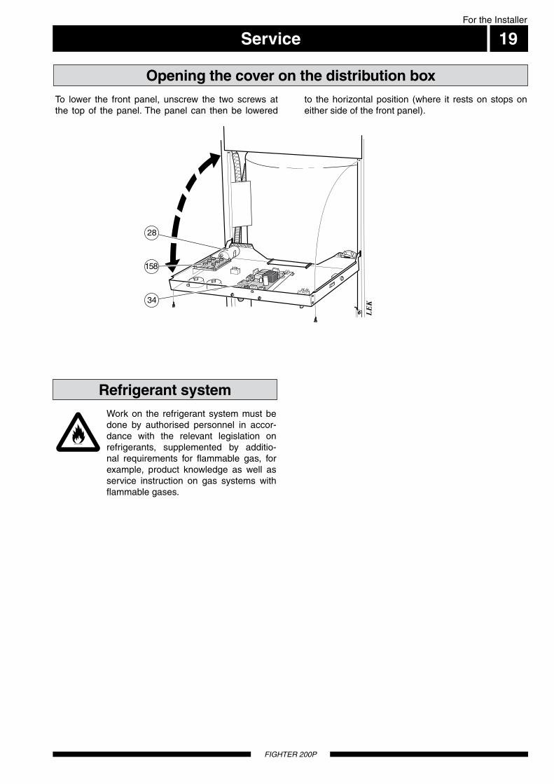
To lower the front panel, unscrew the two screws at the top of the panel. The panel can then be lowered
to the horizontal position (where it rests on stops on either side of the front panel).
Work on the refrigerant system must be done by authorised personnel in accor-dance with the relevant legislation on refrigerants, supplemented by additio-nal requirements for flammable gas, for example, product knowledge as well as service instruction on gas systems with flammable gases.
Opening the cover on the distribution box
Refrigerant system

Wiring diagram
FIGHTER 200P
For the Installer
20

Wiring diagram 21For the Installer
FIGHTER 200P

For the Installer
Components locations
FIGHTER 200P
22
LEK
LEK
LEK
( )
Auto
1
2
3 120 100
40 8060C
0 120TG
2
1 bar 3
0 4TG
( )
Auto
1
2
3 120 100
40 8060C
0 120TG
2
1 bar 3
0 4TG
( )
Auto
1
2
3 120 100
40 8060C
0 120TG
2
1 bar 3
0 4TG
Jättegammal modell
Gammal modell
8
31 32
94
86
30
Fram-ledning
radiatorer
9
6
11
18
59
16
17
44
70
5
78
27
36
33
20
58
108
52
96
109
97
42
62
48
63
87
65
99
Åter-ledning
radiatorer
k.v.v.v.
41
35
518071 50
84
98
85
43
53
1
k.v.v.v.
10349
88
25
104
14873
95
8
31 32
86
30
9
6
11
18
59
16
44
5
19
78
27
36
33
58
108
52
96
109
97
42
62
48
63
87
65
99
k.v.v.v.
41
355180507974 47
43
1
k.v.v.v.
49
88
25
104
73
95
19
47
66 149 15174 150
Radiator system outlet
Radiator sys-tem inlet
Hw. Cw.

List of componentsFor the Installer
23
FIGHTER 200P
1 Immersion heater - 3,0 kW 3 Thermostat for immersion heater 5 Limiting valve, heating system 6 Temperature limiter 7 Temperature limiter, compressor 8 Power switch with mode 0 - 1 - 2 - 3 9 Feeding terminal and clock thermostat 11 Terminal block for fan switch 16 Circulation pump 17 Air screw, circulation pump 18 Pushbutton switch for circulation pump 19 Setting knob for limiting valve 20 Exhaust air connector 25 Pushbutton switch for hot water prioritising 26 Motor protection device for compressor 27 Compressor 28 Working capacitor for compressor 30 Indicator lamp "Compressor running/alarm" 31 Indicator lamp "Defrosting on/check filter" 32 Indicator lamp "Immersion heater on" 33 High pressure pressostat 34 Microprocessor card with power pack
35 Capacity setting, circulation pump 36 Exhaust air fan 41 Low pressure pressostat 42 Boiler pressure gauge 43 Boiler thermometer 44 Shutoff valve, pump and supply heating system 47 Safety valve, water heater 48 Expansion valve 49 Filling valve, heating system 50 Shutoff valve, return line heating system 51 Drain valve, heating system 52 Safety valve, heating system 53 Vacuum valve (hidden) 58 Tension load stop for feeding conductor 59 Tension load stop for room thermostat conductor 62 Evaporator 63 Air filter 65 Filter drier 66 Type plate 69 Compressor heater
Connection Setting-out dimensions A B C 70 Flow line, heating system ................................................ Compression ring Ø 22 mm 100 ... 465 ..... 90 71 Return line, heating system ............................................. Compression ring Ø 22 mm 130 ... 465 ..... 190 73 Cold water connection ..................................................... Compression ring Ø 22 mm 180 ... 465 ..... 290 74 Hot water outlet from water heater .................................. Compression ring Ø 22 mm 295 ... 465 ..... 345 77 Side access panel to valve connections 78 Filter box (hidden) 80 Drain connection, heating system ................................... R 15 utv 82 Room thermostat (accessory) 84 Ventilation opening 85 Expansion vessel 86 Temperature sensor from evaporator 88 Temperature sensor from immersion heater & hot water prioritising 90 Ventilation connection for exhaust air .............................. Ø 125 mm .................... 2095 ...... 295 ..... 160 91 Ventilation connection for vented air ................................ Ø 125 mm .................... 2095 ...... 295 ..... 485 94 Temperature sensor for working compressor 95 Overflow pipe, safety valve water heater 96 Overflow pipe from heating system safety valve 97 Condensate drain from fan box 98 Overflow water discharge ................................................ PVC-pipe, 32 mm outer diameter 99 Collecting funnel, waste water 103 Serial number sign104 Temperature and pressure valve107 Expansion vessel, tap water108 Tundish from safety valve109 Tundish from pressure valve148 Pressure reduction valve149 Connection for flexible hose to CW-side150 Connection for flexible hose to heating-side
151 Filling valve, heating system cw-side158 Circuit board for fan speed

Dimensions
FIGHTER 200P
For the Installer
24
Dimensions and setting-out coordinates
A, B och C ska vara 100 % Rödoch 100 % Gul i PB
Undvik rördragning inom streckmarkeratområde för att underlätta service
Skyddsklenspänning Ø 16
Frånluft Ø 125Avluft Ø 125
Elektriskmatning Ø 25
Dockning Ø 16
91 90
A15
Stä
llbar
15
– 40
250
45
Min avstånd10 mm från vägg
Lucka på båda sidor
Erforderligt utrymme för demontering av övre frontlucka
77
B615
115
C 355
600
2095
440115
295
70
35
40 20
35
70
A, B and C: see "Connection" in "Component list". Pipes must not be run from the floor in the area indi-cated by dots.
A clear space of 500 mm is needed in front of the heat pump for servicing.
Principle of dimensioning
Klämring
Klemmring
Cu-rör
Kupferrohr
Space required for removal of upper front access panel
Minimum distance from wall 10 mm
Safety low voltage ø 16
Electrical feeding ø 25
Docking ø 16
Exhaust air ø 125 Vented air ø 125
Compression ring Copper pipe
Access panel on both sides
When running pipes in the hatched area to facilitate servicing.
Adj
usta
ble
15-4
0

Enclosed kit 25For the Installer
FIGHTER 200P
Accessories
Expansion vessel, tap water (is delivered separately)
LEK
107
Top cabinet 245 mm. Part no 089 424Top cabinet 345 mm. Part no 089 426Top cabinet 385 — 535 mm. Part no 089 428
Top cabinetA top cabinet is available as an accessory to conceal the ventilation ducts above the heat pump.
LEK
LEK
Part no 418 645
Clock thermostat
Part no. 418 172
Earth cable
LEK
Heightening consoleHeight: 125 mm
Part no 089195
LEK
Bracket(is delivered separately)

Technical specifications
FIGHTER 200P
26
Exhaust air fan power consumption (DC) 25–140 W
Required ceiling height 2 185 mm
Depth 615 mm
Total volume 240 liter
Water heater volume 170 liter
Supply voltage 230 V~ 1-phase + N
Immersion heater power rating 3,0 kW
Protection IP 21
Maximum pressure in double jacket vessel 0,25 MPa (2,5 bar)
Refrigerant quantity 420 g
Cut-in temperature for compressor 50 °C * (Controlled by a separate sensor)
Cut-in temperature for immersion heater 49 °C *
Setting area for the limiting valve 38 – 55 °C
Cut-out temperature, temperature limiter for immersion heater 88 °C
Sound power level** 46 – 50 dB(A)
Break pressure for high pressure pressostat 2,45 MPa (24,5 bar)Break pressure for low pressure pressostat 0,15 MPa (1,5 bar)
Height (excl. feet 15-40mm) 2 095 mm
Width 600 mm
Net weight 195 kg
Volume in double jacket 70 liter
Expansion vessel volume, tap water 18 liter
Max operating current 16,7 A
Circulation pump power rating 100 W
Compressor power rating 550 W
Maximum pressure in water heater 0,9 MPa (9 bar)
Design pressure in double jacket volume 0,25 MPa (2,5 bar)
Refrigerant type R290 (propane)
Cut-out temperature for compressor 53 °C *
Cut-out temperature for immersion heater 52 °C *
Cut-out temperature, termostat for immersion heater 70 °C
Cut-out temperature, temperature limiter for compressor 88 °C
Sound level in room where installed*** 42 – 46 dB(A)
* Concerns settings on delivery** A-weighted sound power level (LWA). The value varies with the selected fan curve.
*** A-weighted sound pressure level (LpA). The value varies with the damping capacity of the room. These values apply with a damping of 4 dB.
Expansion vessel volume, heating system 12 liter
IP 21
For the Installer
Inlet temperature 40 °C
COP 2,60
Total Power input 0,535 kW
Exhaust air: Air flow 150 m3/h
Inlet wet bulb temperature 12 °C
COP and heating capacity according to EN 14511-2:2004
Heating capacity 1,35 kW
Current 2,7 A
Rating condition
Inlet dry bulb temperature 20 °C
Water:
Outlet temperature 45 °C

27
FIGHTER 200P

FIGHTER 200P
28


PL
NO
NL
FI
DK
DE
CZ
NIBE – Haato OY, Valimotie 27, 01510 Vantaa
3C Broom Business Park, Bridge Way, Chesterfield S41 9QG
Puh: 09-274 697 0 Fax: 09-274 697 40 E-mail: [email protected] www.haato.fi
NIBE-BIAWAR Sp. z o. o. Aleja Jana Pawła II 57, 15-703 BIAŁYSTOKTel: 085 662 84 90 Fax: 085 662 84 14 E-mail: [email protected] www.biawar.com.pl
NIBE AB, Jerikoveien 20, 1067 OsloTel: 22 90 66 00 Fax: 22 90 66 09 E-mail: [email protected] www.nibe-villavarme.no
NIBE Energietechniek B.V., Postbus 2, NL-4797 ZG WILLEMSTAD (NB)Tel: 0168 477722 Fax: 0168 476998 E-mail: [email protected] www.nibenl.nl
Vølund Varmeteknik, Filial af NIBE AB, Brogårdsvej 7, 6920 VidebækTel: 97 17 20 33 Fax: 97 17 29 33 E-mail: [email protected] www.volundvt.dk
NIBE Systemtechnik GmbH, Am Reiherpfahl 3, 29223 CelleTel: 05141/7546-0 Fax: 05141/7546-99 E-mail: [email protected] www.nibe.de
NIBE CZ, V Zavetri 1478/6, CZ-170 00 Prague 7Tel: +420 266 791 796 Fax: +420 266 791 796 E-mail: [email protected] www.nibe.cz
CHNIBE Wärmetechnik AG, Stadlerstrasse, CH-8404 WinterhurTel: (52) 6470030 Fax: (52) 6470031 E-mail: [email protected] / [email protected] www.nibe.ch
ATKNV Energietechnik GmbH, Gahberggasse 11, 4861 SchörflingTel: +43 (0)7662 8963-0 Fax: +43 (0)7662 8963-44 E-mail: [email protected] www.knv.at
NIBE AB Sweden, Box 14, Järnvägsgatan 40, SE-285 21 MarkarydTel: +46-(0)433-73 000 Fax: +46-(0)433-73 190 E-mail: [email protected] www.nibe.eu
GBNIBE Energy Systems Ltd,Tel: 0845 095 1200 Fax: 0845 095 1201 E-mail: [email protected] www.nibe.co.uk


![INVITATION_TO_LOVE_2005 200p 21.1.2011[1]](https://static.fdocuments.in/doc/165x107/577d2ecb1a28ab4e1eb00199/invitationtolove2005-200p-21120111.jpg)