6 2014 PPP 1519F3 Foil Bearing presentation - TRIBGROUP...
19
A Shimmed Bump Foil Bearing: Measurements of Drag Torque, Lift Off Speed, and Identification of Stiffness and Damping Coefficients Luis San Andrés Principal Investigator Joshua Norsworthy Graduate Research Assistant May 2014 TRC Project 32513/1519F3 TRC-B&C-01-2014 EFFECT OF SHIMMING ON THE ROTORDYNAMIC FORCE COEFFICIENTS OF A BUMP‐TYPE FOIL BEARING
Transcript of 6 2014 PPP 1519F3 Foil Bearing presentation - TRIBGROUP...

A Shimmed Bump Foil Bearing: Measurements of Drag Torque, Lift Off Speed, and Identification of Stiffness
and Damping Coefficients
Luis San AndrésPrincipal Investigator
Joshua NorsworthyGraduate Research Assistant
May 2014
TRC Project 32513/1519F3
TRC-B&C-01-2014
EFFECT OF SHIMMING ON THE ROTORDYNAMIC FORCECOEFFICIENTS OF A BUMP‐TYPE FOIL BEARING

2
Introduction Gas Foil BearingsBump-type foil bearings (BFB) : a gas film in series with a compliant
under-spring is a choise support for microturbomachinery (<400kW)Typically top foil, shaft or both oated to minimize wear & reduce friction
Issues:• Expensive highly engineered
elements
• Nonlinear substructure: contributes to sub synchronous rotor whirl
motions
• Thermal management advised
• LOW load capacity (compared to oil lubricated bearings)

Justification & Past Work
Kim and San Andrés (2009) Trib. Trans., Vol. 52
Sim et al. (2012) J.Tribol. Vol.134Oil free turbocharger on shimmed foil bearings
Shimmed (mechanically preloaded) BFBs are a low cost way to ensure stable performance.
Sim et al. (2014) Proc. ASME Turbo Expo 2014Three pad BFB
Issue: BFB supported rotors often show large sub synchronous whirl motions.
Prior art:shimmed BFB
increases the onset speed of rotor instability and
reduces the amplitude of sub
synchronous whirl motions

Test BFB and shims
Shims placed 120° apart, stretch axially through bearing
Bearing dimensionsL= 38.1mmD = 36.5 mmL/D~ 1.03
Shims have one surface with adhesive.
Shims press some bumps closer to the rotor
L=38.1 mm, arc=12o,Thickness =30 µm,50 µm
Other BFB dimensions. Add slide
FB radial clearance, cnom=(DI -Ds)/2= 0.120 mm

cnom: Nominal bearing clearance
tS : Shim thickness
NS : Number of shims
θ : Angular coordinateθp : Angular
distance between consecutive
shimsθ1 : Angular
coordinate of the first shim
Clearance profile: ( ) 111 cos
2 2s
nom s S pnom
tc c t Nc
Clearance of shimmed BFB
The clearance of a shimmed bearing is periodic resembling a tri-lobe or three pad bearing. The bearing clearance reduces at shim locations.

Rotordynamic test rig
Max. operating speed: 80 krpmTurbocharger driven rotorRegulated air supply: 7.58 bar (110 psig)Test journal diameter:36.5 mm
TC cross-sectional view
turbocharger, Model T25, donated by Honeywell Turbo Technologies
Journal press fitted on shaft stub
Bearing

Drag TorqueSpeed up to 60 krpm, steady state operation, and deceleration to rest.
Lift off speed occurs at the lowest torque denoting airborne operation
Top shaft speed = 60 krpm

Start up drag torque (dry friction)
Bearing with 30 µm shims
Bearing with 50 µm shims
Original bearing
Torque max variability : ±5 N-mm Max. variability : ±2.5 krpm
Bearing with 30 µm shimsOriginal bearing
Bearing with 50µm shims
TfRW
Drag torque and rotor lift off
speed increase with specific load
Friction factor of shimmed BFBsincreases with shim thickness
and decreases with specific load
Peak startup torque Bearing lift off speed

Breakaway friction factor
fstartup
fbreakaway=Tbreakaway/RW
Original bearing
Breakaway f agrees well with f from startup tests.
Torque meter
Differences at W/LD~20 kPa are due to wear. Tests conducted after 200 cycles of rotor start and stop.
Friction coefficientf = (Torque)/(Radius*Static load)
Torque to turn manually shaft inside bearing.

Airborne friction factor
f for the BFB with 30µm shims is equal to that of
the original bearing.
f for the BFB with 50 µm shims is 15% larger than f
for the original bearing.
f ~ 0.1
f ~ 0.04 Friction factor decreases with specific
load

Rotordynamic test rig
Shaft speed: 50 krpm (833 Hz)Displacement amplitude: 20 µmVertical specific load W/LD:14.3 kPa
Test frequency range: up to 450 HzDynamic load: up to 250 N
Eddy current sensor
5 cm
Accelerometer
BEARING
Oil inlet
Oil outlet
TC center housing
Air outlet
Shaft stub
Turbine housing
Stinger connection to shaker
Load sensor
Accelerometer
Static load
Static load(force gauge)
Journal
Squirrel cage (Soft
elastic support)
Y X
Thermocouple
Thermocouple
BEARING

Parameter IdentificationApply: sine sweep load excitations (200-400 Hz), amplitude controlled (20 µm).Measure: bearing absolute accelerations and displacements relative to journal
X XX
Y YY
S S2SX XXX XX XY XY
YX YX YY YY S SY Y2S
C KMF AxK j C K j C j
yK j C K j C C KF AM j
( ) ( )
( ) ( )
( )
( )System EOM
Frequency domain analysis yields stiffness and damping coefficients

BFB stiffnesses, KOriginal bearing Bearing with 30 µm shims
Bearing with 50 µm shims
BFB direct stiffnesses increases with excitation
frequency, not significantly affected by shims
X
Y
14.3 kPaspecific
Shaft speed50 krpm (833 Hz)W/LD=14.3 kPa
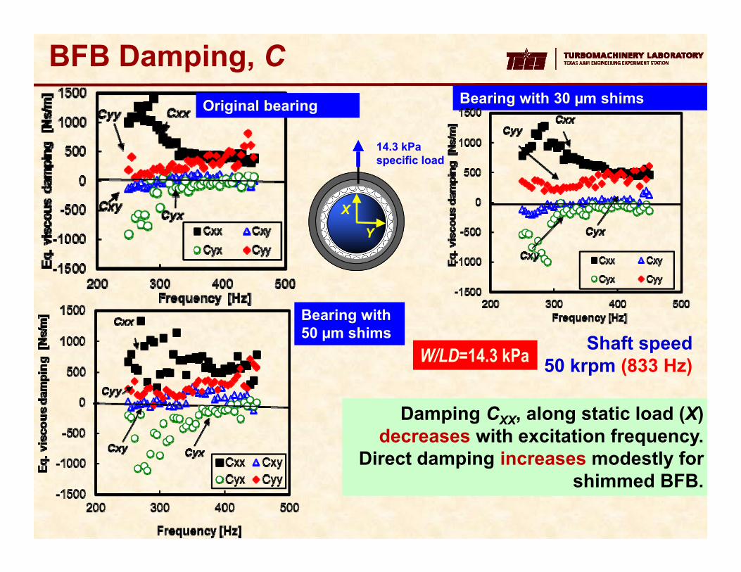
BFB Damping, COriginal bearing Bearing with 30 µm shims
Bearing with 50 µm shims
Damping CXX, along static load (X) decreases with excitation frequency.
Direct damping increases modestly for shimmed BFB.
X
Y
14.3 kPa specific load
Shaft speed50 krpm (833 Hz)W/LD=14.3 kPa

BFB loss factor,
BFB loss factor (γ~0.39-0.48) is not affected by shim thickness or rotor speed
X
Y
14.3 kPa specific load
C KProportional structural damping model
0 0
end endt t
Mt t
T TVE dt E dt
z C z z K z
Viscous energy dissipation (Ev) = structural material energy dissipated (Em) over entire duration of load excitation (t=0 - tend)
Bearing
Configuration
Loss
Factor
0 krpm
Original 0.39
30 m
shims0.48
50 m
shims0.39
50
krpm
Original 0.43
30 m
shims0.45
50 m
shims0.43
0
0
end
end
t
t
t
Tt
T dt
dt
z C z
z K z

TC vibration measurements
Rotor on shimmed BFB does not show sub synchronous vibrations
Original bearing
Bearing with 30 µm shims
Bearing with 50 µm shims

FB post test inspection

• Shimmed (50 μm) BFB shows LARGEST DRY friction coefficient (f ~0.80-0.40)
• Once airborne, friction factor is small [ f < 0.04-0.10]. BFB with 50 μm shims has 15% larger f than original BFB and BFB with 30 μm shims).
• Rotordynamic coefficients: shim thickness does not affect BFB stiffnesses; however, it increases the damping coefficients.
• Shim thickness does not change the BFB loss factor γ~0.38-0.45.
• TC rotor supported on shimmed BFB (50 m) demonstrates operation free of sub synchronous whirl.
Conclusions
??
How? Yet unknown. MS thesis will provide rationale

19
Questions(?)