6-11. STEERING KNUCKLE AND ARM MAINTENANCE … Kingpin.pdf · TM 9-2320-289-34 6-11. STEERING...
7
TM 9-2320-289-34 6-11. STEERING KNUCKLE AND ARM MAINTENANCE (ALL EXCEPT M1009). This task covers: a. Disassembly b. Assembly INITIAL SETUP: Equipment Condition Materials/Parts ● Steering tie-rod removed. • One gasket (See TM 9-2320-289-20) ● Two seals ● Connecting rod disconnected from steering ● Eight Iockwashers arm (left side). (See TM 9-2320-289-20) ● Grease (Item 36, Appendix B) ● Front axle shaft removed, (See paragraph 6-4) Tools/Test Equipment General Safety Instructions ● Socket wrench adapter, J-26871-A ● Nuts at steering arm, or bolts at upper ● Torque wrench kingpin bearing cap, must be removed alternately and with caution. a. DISASSEMBLY WARNING Nuts at steering arm or bolts at upper kingpin bearing cap must be removed alternately and with caution. Compression spring underneath steering arm or bearing cap could fly up during removal, causing serious injury to personnel. 6-71
Transcript of 6-11. STEERING KNUCKLE AND ARM MAINTENANCE … Kingpin.pdf · TM 9-2320-289-34 6-11. STEERING...

TM 9-2320-289-34
6-11. STEERING KNUCKLE AND ARM MAINTENANCE (ALL EXCEPT M1009).
This task covers: a. Disassembly b . A s s e m b l y
INITIAL SETUP:
Equipment Condition Materials/Parts
● Steering tie-rod removed. • One gasket(See TM 9-2320-289-20) ● Two seals
● Connecting rod disconnected from steering ● Eight Iockwashersarm (left side). (See TM 9-2320-289-20) ● Grease (Item 36, Appendix B)
● Front axle shaft removed,(See paragraph 6-4)
Tools/Test Equipment General Safety Instructions
● Socket wrench adapter, J-26871-A ● Nuts at steering arm, or bolts at upper● Torque wrench kingpin bearing cap, must be removed
alternately and with caution.
a. DISASSEMBLY
WARNING
Nuts at steering arm or bolts at upper kingpin bearing cap must beremoved alternately and with caution. Compression spring underneathsteering arm or bearing cap could fly up during removal, causing seriousinjury to personnel.
6-71

TM 9-2320-289-34
6-11. STEERING KNUCKLE AND ARM MAINTENANCE (ALL EXCEPT M1009)(Con’t).
NOTE
• On left side, steering arm (3) is installed to steering knuckle (8) with 4nuts (2). On right side, upper kingpin bearing cap is installed tosteering knuckle with 4 bolts and Iockwashers.
● Left side disassembly is given.
1. Remove 4 nuts (2) alternately at steering arm (3). Remove steering arm, spring (4), andspring retainer (5). Remove gasket and discard. If present, discard 4 Iockwashers.
2 . Remove 4 bolts (16), Iockwashers,and lower kingpin bearing cap (15)from steering knuckle (8). DiscardIockwashers,
TA50563
6-72

TM 9-2320-289-34
6-11. STEERING KNUCKLE AND ARM MAINTENANCE (ALL EXCEPT M1009)(Con’t).
3. Remove kingpin bushing (7) from topof steering knuckle (8). Removesteering knuckle from axle housing(9) .
NOTE
Upper kingpin (6) is tightened to 550 lb.-ft, (746 N.m).
4. Remove seal (10) from upper kingpin(6). Remove upper kingpin from axlehousing (9). Discard seal.
5. inspect upper kingpin (6) and kingpinbushing (7) for damage. Replace ifdamaged.
TA50564
6-73

TM 9-2320-289-34
6-11. STEERING KNUCKLE AND ARM MAINTENANCE (ALL EXCEPT M1009)(Con’t).
6 . Remove seal (14) and bearing (13). Inspect bearing for damage and binding, Replace ifdamaged or binding. Discard seal. If damaged, remove bearing cup (12) and retainer (11).
7 . Inspect all grease fittings and replace if damaged.
b. ASSEMBLY
NOTE
● On left side, steering arm is installed to steering knuckle (8) with 4nuts. On right side, upper kingpin bearing cap is installed to steeringknuckle with 4 bolts and Iockwashers.
● Left side assembly is given,
• Seal (14) will protrude slightly from surface of axle housing (9) flangewhen installed.
1. If removed, assemble retainer (11) and bearing cup (12), and install to axle housing (9)flange. Fill area in retainer with grease. Grease bearing (13) and install, Install new seal (14).
TA60565
6-74
TM 9-2320-289-34
6-11. STEERING KNUCKLE AND ARM MAINTENANCE (ALL EXCEPT M1009)(Con’t).
2 . Install upper kingpin (6) to axle housing (9) and tighten to 550 Ib.-ft. (746 N.m). Install newseal (10) to upper kingpin with lip facing up.
3 . Grease upper kingpin (6) and install steering knuckle (8) to axle housing (9).
TA50566
6-75

TM 9-2320-289-34
6-11. STEERING KNUCKLE AND ARM MAINTENANCE (ALL EXCEPT M1009)(Con’t).
4 . Install lower kingpin bearing cap (15)with 4 new Iockwashers and bolts(16). Tighten bolts to 80 Ib.-ft.(108 Nom).
5 . Install kingpin bushing (7) to top ofsteering knuckle (8) with ridge onbushing indexed with slot in axlehousing (9).
TA50567
6 - 7 6
TM 9-2320-289-34
6-11. STEERING KNUCKLE AND ARM MAINTENANCE (ALL EXCEPT M1009)(Con’t).
CAUTION
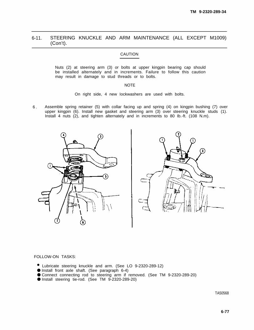
Nuts (2) at steering arm (3) or bolts at upper kingpin bearing cap shouldbe installed alternately and in increments. Failure to follow this cautionmay result in damage to stud threads or to bolts.
NOTE
On right side, 4 new Iockwashers are used with bolts.
6 . Assemble spring retainer (5) with collar facing up and spring (4) on kingpin bushing (7) overupper kingpin (6). Install new gasket and steering arm (3) over steering knuckle studs (1).Install 4 nuts (2), and tighten alternately and in increments to 80 Ib.-ft. (108 N.m).
FOLLOW-ON TASKS:
• Lubricate steering knuckle and arm. (See LO 9-2320-289-12)● Install front axle shaft. (See paragraph 6-4)● Connect connecting rod to steering arm if removed. (See TM 9-2320-289-20)● Install steering tie-rod. (See TM 9-2320-289-20)
TA50568
6-77