OVER THE KNUCKLE 1-TON STEERING INSTALLATION …
20
TOOLS NEEDED OVER THE KNUCKLE 1-TON STEERING INSTALLATION INSTRUCTIONS • Grinder with cutoff wheel, sawzall, cutting torches, or a plasma cutter • Welder (for optional sway bar mounts) • Hand drill with a ½ chuck. • 5/8 drill bit with ½ shank • 11/16 drill bit with ½ shank (optional, but will prolong reamer lifespan) • 7 degree reamer (1.5 inches per foot) • Cutting/reaming oil (optional, but will prolong reamer lifespan) • Common hand or air tools. • A good penetrating oil (such as PB Blaser) • Drag Link (1) • Tie Rod (1) • ES2233L (1) • ES2234R (1) • ES2026R (1) • ES2027L (1) • Jam Nuts RH (2) • Jam Nuts LH (2) • Poly bushing (1) • Cotter Pins (4) • Zerk Fittings (4) • Sway Bar Mounts (Opt.) HARDWARE Please read the mounting instructions below carefully before attempting to install. Thank you for purchasing your new 1-ton steering kit from JcrOf- froad! Checkout our website, www.jcroffroad.com for other great off-road products. Be sure to rate and review our product online. If you have any questions or are missing parts, please don’t hesitate to call us at 269-353-1184 x20! • Large adjustable wrench or 1-5/16" open end wrench (for jam nuts) • Loctite® 271 Red (extremely important, do not skip this!) • Paint marker • Jack • Jack stands • Hammer • Tape measure
Transcript of OVER THE KNUCKLE 1-TON STEERING INSTALLATION …

TOOLS NEEDED
OVER THE KNUCKLE1-TON STEERINGINSTALLATION INSTRUCTIONS
• Grinder with cutoff wheel, sawzall, cutting torches, or a plasma cutter
• Welder (for optional sway bar mounts)
• Hand drill with a ½ chuck.
• 5/8 drill bit with ½ shank
• 11/16 drill bit with ½ shank (optional, but will prolong reamer lifespan)
• 7 degree reamer (1.5 inches per foot)
• Cutting/reaming oil (optional, but will prolongreamer lifespan)
• Common hand or air tools.
• A good penetrating oil (such as PB Blaser)
• Drag Link (1)
• Tie Rod (1)
• ES2233L (1)
• ES2234R (1)
• ES2026R (1)
• ES2027L (1)
• Jam Nuts RH (2)
• Jam Nuts LH (2)
• Poly bushing (1)
• Cotter Pins (4)
• Zerk Fittings (4)
• Sway Bar Mounts (Opt.)
HARDWARE
Please read the mounting instructions below
carefully before attempting to install.
Thank you for purchasing your new 1-ton steering kit from JcrOf-
froad! Checkout our website, www.jcroffroad.com for other great
off-road products. Be sure to rate and review our product online. If
you have any questions or are missing parts, please don’t hesitate
to call us at 269-353-1184 x20!
• Large adjustable wrench or 1-5/16" open end wrench (for jam nuts)
• Loctite® 271 Red (extremely important, do not skip this!)
• Paint marker
• Jack
• Jack stands
• Hammer
• Tape measure

Thanks for purchasing our 1-ton steering upgrade! With proper installation and maintenance this system should give you years of
worry free operation.
Please read these instructions in full before proceeding with the install. We recommend you have a trusted 4wd shop install this
product if any part of this guide seems difficult.
Chuck the rear tires. Raise the Jeep up and place jack stands. Now pull the front tires.1
It is good practice to measure from the center of each TREs on the knuckles and save that measurement for later to help with your alignment later in the install.
2

Remove your stock steering from the pitman arm. Some percussive persuasion with a hammer might be needed.
4
Remove your stock steering from the knuckles. The stock castle nuts use a 3/4” deep well socket, if your stock TREs are worn you may need to put a jack under the TRE body and put some pressure on them (up into the knuckle.) This should allow you to loosen the nuts.
3

Remove your steering stabilizer from its mount on the axle. You should now be able to remove the whole stock steering assembly.
Remove the sway bar links and any hardware on the axle mounts.
Optionally, pull the front coil springs at this time.
5
6
7

If you plan on cutting with flame, plasma, or welding braces in, pull the axle side of the trackbar, and bungee cord it out of the way.
Time to get cutting! Using the method of your choice, trim the coil buckets and sway bar mounts as show in the photos below. You will be removing the steering stabilizer bracket completely. It’s also a good time to make more clearance for your track bar at full droop too. Trim both coil buckets back enough that you just have enough room for the width of the coil springs to sit on the perch.
8
9
Clean up cuts with a grinder (a 4" sanding flap wheel works great) and use the same grinder and a stainless steel wire brush cup to clean off any paint and rust from the axle brackets and inner axle "C"s.
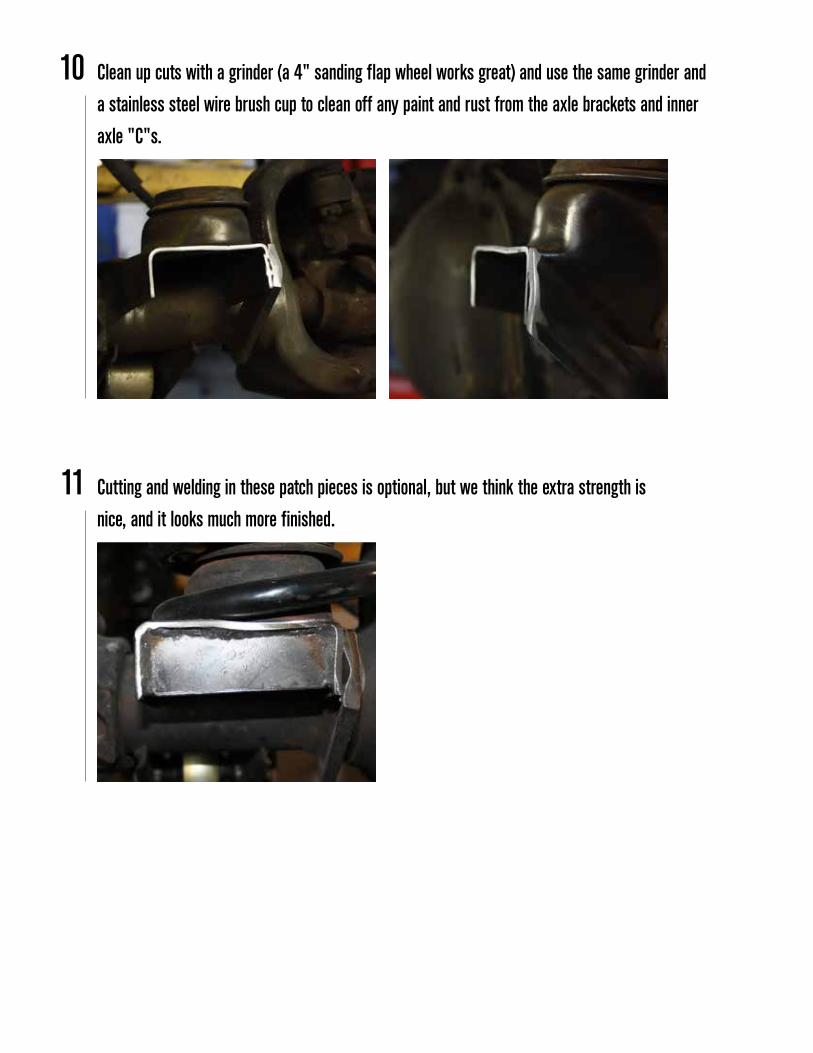
Cutting and welding in these patch pieces is optional, but we think the extra strength isnice, and it looks much more finished.
10
11

Notice how close the edge of the coil spring is to the end of the coil bucket, this is to get as much clearance as possible for the tie rod.
12
Ream the pitman arm.13If you have a vice or drill press with a 1⁄2" chuck you may want to remove the pitman arm to ream it in the press. If not continue to 14:b.
If you need to remove the pitman arm use a 1-5/16" socket to loosen the pitmannut, then put some pressure on the pitman arm with a pitman arm puller.
If you don’t feel the arm start to come off, don’t force the puller, they are easy tobreak. Just leave tension on the arm with the puller and tap all around the arm(the box end) with a hammer.
Keep alternating pounding and tightening the puller and it will come off. Usingsome penetrating oil the night before will work wonders as well.
Once it’s removed, clamp it securely and proceed to 13:b.
A
I
II
III
IV

If you have an 11/16th drill bit, drill the current hole out to that. If you only havethe 5/8" bit, then use that, it will work, but will require more reaming.Be sure you are drilling parallel to the original hole.
I
Start to ream the pitman arm from the bottom, using more cutting oil as needed.Be sure you are reaming parallel to the drilled hole. Hold the drill parallelthe whole time, as a wobbly drill leads to a wobbly hole, which will resultin wobbly TREs.
III
Once the hole is drilled, chuck up the reamer and lube it with cutting oil.
II
Once the TRE fits through the hole and allows you to thread the castle nut ondeep enough for the cotter pin to go through; you are done with the pitman arm.
If you pulled the arm to do the reaming on a vice or drill press, re-install it now. Be sure to use the original lock washer, and also add red Loctite to the nut. Torque it to factory specs.
There is no easy way to measure the depth of your taper, so be sure to checkfrequently with one of the TREs from the drag link.Be sure you use one of the TREs from the drag link to check yourprogress, as they have a deeper taper than the ones from the tie rod.
V
VI
IV
If you want to ream the pitman arm on the vehicle that is fine as well.B

Start to ream the knuckles from the TOP, using more cutting oil as needed.Be sure you are reaming parallel to the drilled holes. Hold the drill parallel the whole time, as a wobbly drill leads to a wobbly hole, which will result in wobbly TREs.
C
There is no easy way to measure the depth of your tapers, so be sure to check frequently with one of the TREs from the tie rod.
D
Once the TRE fits through the hole and allows you to thread the castle nut on deep enough for the cotter pin to go through; you are done with the both knuckles.
E
Once the holes are drilled, chuck up the reamer and lube it with cutting oil.
B
Ream the knuckles. This may be easier using a vice, but replacing your ball joints might be necessary to do this.
14
Drill both left and right knuckle TRE holes out to 5/8".Be sure you are drilling parallel to the original hole.
A
Reinstall the track bar (if removed.)15
Temporarily assemble (if unassembled) the tie-rod and drag link.16

Loosely install the tie-rod into the knuckles. Using a tape measure and the measurement from step 2, spin the tie-rod forward or back until you reach that measurement. Keep in mind that you are looking for “0” toe when finished.
17
18 Loosely install the drag-link into the pitman arm and tie-rod. Turn the drag-link forward or backwards until steering wheel is close to center (at ride height.)
Turning the wheels lock to lock, and cycling the suspension from compression to droop (thesprings removed at this point will be helpful) check for clearances of the tie-rod to the coils, diffcover, and track-bar.
19

Sway bar relocation. Be sure both the inner portion of the coil bucket and inner "C" are free of paint, dirt and rust. Because of limitless configurations of sway bars and front end setups, positioning of these will need to be messed with. Use these photos as a start.
21
Just like with the trackbar, make sure that the tie-rod and drag link clear the mounts, bracing, and attached sway bar end links at lock to lock and full compression to full droop.
22
Any clearance issues at the coils will need to be eliminated by adjusting the steering stops out on either side. Clearance issues with the track bar can be solved by rotating the track-bar slightly if adjustable on both ends, or cutting and welding the track-bar in the new rotated position. This can very from vehicle to vehicle and brand to brand. Sometimes this step will not be needed, or only needed for extreme suspension travel.
20

Once everything is tacked and clearance is tested, completely weld the rectangle and mount itselfbefore adding in the long and triangle bracing pieces as shown.
24
The rods themselves come unfinished, so take the time now to put a good coat of paint on them. The best way we have found to not foul up the threads, is to leave the Tie Rod Ends in the rods and wrap them with masking tape. This will keep paint off the jam nuts, threads, and TRE body itself.
25
We recommend a few good coats of primer and the top coat of your choice.A
Be sure to weld the rectangle spacer from the coil bucket to the sway bar mount itself. This assures that the mount isn’t relying only on the small weld to the cast knuckle for strength.
23

Remove the dust boot (if equipped) on the ES2233L (longest TRE) and replace it with thesupplied polyurethane spacer. The polyurethane bushing will act as the seal for grease.
27
Install the tie rod once more. Now tighten the castle nuts. Be sure the castle nuts are very tight, and that the hole for the cotter pin is visible between the points of the nut once it’s tight. Install all the tie rod cotter pins.
28
Reassemble the tie rod (if you disassembled it for paint) being sure that the same amount ofTRE threads are showing on each side of the rod.
26
A For added corrosion protection you can use anti-seize on the threads of the tie rod ends. This will ensure adjustments are easy down the road.

Reassemble the drag link (if you disassembled it for paint) being sure that the same amountof TRE threads are showing on each side of the rod.
Bolt the drag link on with the longest TRE to the passenger side. Be sure the castle nuts arevery tight, and that the hole for the cotter pin is visible between the points of the nut once it’stight. (See Figure 1)
29
30
For added corrosion protection you can use anti-seize on the threads of the tie rodends. This will ensure adjustments are easy down the road.
A

Twist the rod forward or backward until the front tires are pointing straight forward.
Lower the vehicle onto its tires.
33
34
Inside the vehicle, turn the steering wheel from lock to lock and find the center of its travel.Turn the key off and lock the wheel at a point near there.
32
Bolt the tires and wheels back on the vehicle and center the steering as best you can visibly.31With a helper and a tape measure, measure the distance between a common point on the front of the tires, and the rear of the tires. Be sure and use the same reference points for both measurements.
Spin the tie rod forward or backward to adjust the toe-in. Your looking for anywhere from 0" – 1/8" of toe-in. Double check your measurements, add some red Loctite to the TRE threads, and tighten the jam nuts down.
A
B

Once everything is centered double check your measurements, clean off any anti-seize youadded under where the jam nut will rest, add some red Loctite to the TRE threads, andtighten the jam nuts down.
Take your paint marker and put a line across each of the jam nuts and the rods. These alignment marks will allow you to quickly see if your jam nuts are loosening.It is VERY important that these jam nuts stay tight at all times. Always use red LocTite when you loosen or adjust them.
37
38
Unlock the steering wheel and sight down both front tires. Using the sidewalls and the reartires as a reference point; align them straight ahead by turning the steering wheel left or right.
Once the tires are pointing straight ahead, twist the drag link forward or backward to align the steering wheel to top center. The wheel may be off center to the left or right initially, but takeit to center via the shortest way.
35
36

Be sure and grease all the TREs after the install, and frequently after that. This will greatlyextend their lifespan.
It’s always a good idea to have the front end professionally aligned to guarantee proper tirewear.
39
40
The steering wheel won’t center correctly, or the vehicle turns farther in one direction that the other - Verify that you centered the steering gearbox properly before the install. Call us to verify the drag link measurement for your specific vehicle.
POTENTIAL PROBLEMS
If you have any problems, questions, or concerns please feel to contact us at [email protected] or (269) 353-1184 x20.
*


1TS-OTK - 1-TON STEERING UPGRADE - OVER THE KNUCKLE
Additional Parts
Polyurethane Spacer X1
Bolt Pack: Misc Bolt: o 4 - Greese Zerts o 4 - Cotter Pins o 1 - M10 - 1.5 Low Head Bolt
Item Code LegendEX: 1TS-OTK-21 -21 : 21” Drag Link -215 : 21.5” Drag Link
Revised: 05/10/16