58235646-Limits
70
-
Upload
rakesh-kumar -
Category
Documents
-
view
53 -
download
1
Transcript of 58235646-Limits


INTRODUCTION TO LIMITS FITSINTRODUCTION TO LIMITS, FITS, TOLERANCE AND GD&TTOLERANCE AND GD&T
03‐02‐08

PURPOSE OF MASS PRODUCTIONPURPOSE OF MASS PRODUCTION (Interchangeability)
I d ti b i t h bilitIn mass production, by interchangeability,identical components manufactured bydiff t l d diff tdifferent personnel under differentenvironment, can be assembled and replacedith t f th tifi ti d i thwithout any further rectification during the
assembly stage, without affecting thef ti i f th t hfunctioning of the component whenassembled

NECESSITY OF THE LIMIT SYSTEM
If components are to be interchangeable, theyneed to be manufactured to the same size whichis not possible, when they are mass produced.
It b t th t t d i tIt becomes necessary to the operator to deviateby a small margin from the exact size (BASICSIZE)SIZE).
At the same time, the deviated size should not,affect the quality of the assembly. This sort ofdimensioning is known as limit dimensioningg g

A system of limits is to be followed as a standard for theA system of limits is to be followed as a standard for the limit dimensioning of components
Various system of limits and fits are followed by differentVarious system of limits and fits are followed by different countries based on the ISO specifications.
Th t f li it d fit f ll d i t i th tThe system of limits and fits followed in our country is that stipulated by the BIS(BUREAU OF INDIAN STANDARDS)
OTHER SYSTEM OF LIMITS AND FITS
INTERNATIONAL STANDARDS ORGANISATION (ISO)
BRITISH STANDARD SYSTEM (BSS)
( )GERMAN STANDAD (DIN)

TERMINOLOGY‐ THE INDIAN STANDARD SYSTEM OF LIMITS & FITS
Size:
It is a number expressed in a particular unit in the measurement of length
Basic Size:
It is the size based on which the dimensional deviations are given.
Actual Size:
It is the size of the component by actual measurement after f d h ld l b h l f fit is manufactured. It should lie between the two limits of size if
the component is to be accepted

Limits of size:
These are the extreme permissible sizes within which theThese are the extreme permissible sizes within which theoperator is expected to make the component.
Maximum limit of size:
It is the greater of the two limit of sizes.
Minimum limit of size:Minimum limit of size:
It is the smaller of the two limits of sizes.
Hole:
In the BIS system of limits & fits, all internal features of at i l di th hi h t li d i l d i t dcomponent including those which are not cylindrical are designated
as “Hole”Shaft:
In the BIS system of limits & fits, all external features of acomponent including those which are not cylindrical are designatedas shaft.
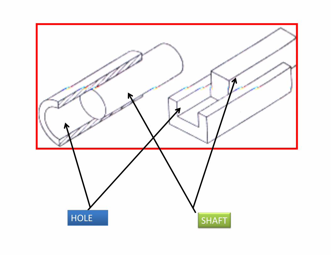
HOLE SHAFT

Deviation:
It is the algebraic difference between a limits of size to its corresponding basic size. It may be positive, negative or zero.
Upper deviation:pp
It is the algebraic difference between the maximum limit of size to its corresponding basic sizemaximum limit of size to its corresponding basic size. Lower deviation:
It is the algebraic difference between the minimum limit of size to its corresponding basic size.

Actual deviation
It is the algebraic difference between the actual size and its corresponding basic size.p g
Tolerance:
It is the difference between the maximum limit of size and minimum limits of size. It is always positive and is expressed only as a number without a signis expressed only as a number without a sign.
Zero line:
In graphical representation of above terms, the zero line represents the basic size. This line is also called as the line of zero deviation.


• Is there any two things identical ?
Wh V i ti ?• Why Variations?

NO
MenM hiMachineMaterial

SHAFTBASIC DIAMETER 20MMBASIC DIAMETER 20MM
20mm

SHAFTDIAMETER : MAY GO UP TO 20.3 mm
20.3 mm

SHAFTSHAFTSPECIFICATION
?
+ 0.30
20- 0.00

SHAFTSHAFTSPECIFICATION
TOLERANCE
+ 0.30
20- 0.00


Dimensions and Tolerance communicate in the size and shape of the part.
A Di i i i l l d iA Dimension is a numerical value expressed in appropriate units of measure and used to define Size, location orientation form or other geometriclocation, orientation, form or other geometric characteristics of the part.
A Tolerance is the total amount that part features are permitted to vary from their specified dimensions.
It is the difference between the maximum and i i li iminimum limit


SOLVE THE PROBLEM
ON THE DRAWINGWHICH LETTER INDICATES A LIMIT TOLERANCE?ON THE DRAWING,WHICH LETTER INDICATES A LIMIT TOLERANCE?
ON THE DRAWING, WHICH LETTER INDICATES A PLUS OR MINUS TOLERANCE?


Fundamental Deviation:Th 28 f d t l d i ti i th BIS tThere are 28 fundamental deviations in the BIS system
represented by letter symbols
The fundamental deviations are for achieving the differentclasses of fits


Schematic representation of the positions of fundamental deviations

Fundamental tolerance:This is also called ‘grade of tolerance’. In the Indian gStandard System , there are 18 grades of tolerances

A high number gives a _____________ tolerance zone.

A high number gives a _____________ tolerance zone.LARGE

Toleranced size:
This includes the basic size, the fundamental deviation and the grade of tolerance.

25H7( toleranced size of a ___________)

25H7( toleranced size of a ___________)HOLE

30h7 ( toleranced size of a _____)

30h7 ( toleranced size of a _____)Shaft

Calculate the tolerance for
a. 25H7
b. 30h7b. 30h7

NO. SIZE OF THE COMPONENT
UPPER DEVIATION
LOWER DEVIATION
MAX. LIMIT OF SIZE
MIN, LIMIT OF SIZE

Exercise :Exercise : 120 G720 g6

NO. SIZE OF THE COMPONENT
UPPER DEVIATION
LOWER DEVIATION
MAX. LIMIT OF SIZE
MIN, LIMIT OF SIZE

FITSFITS

Fit:
It is the relationship that exists between two mating parts, a hole and a shaft., with respect to their dimensional diff b bldifference between assembly
Expression of a fit:
Example
30 H7/g6 (or)
30 H7‐g6 (or)
30H7g6g6

TYPES
1 Cl Fit1. Clearance Fit

Clearance:Clearance:
In a fit the clearance is the difference between the size of the hole and the size of the shaft which isthe size of the hole and the size of the shaft which is always positive.
Clearance fit:
It is a fit which always provides clearance. Here the tolerance zone of the hole will be above the tolerance zone of the shaft.

The limits of the hole are
20 + 0.021 = 20.021 mm
20 + 0 = 20.000 mm
For a shaft 20 g6 we find in the table ‐7
‐2020
So the limits of the shaft are20 ‐ 0.007 = 19.993 mm20 ‐ 0.020 = 19.980 mm

Maximum clearance:
In a clearance fit or transition fit it is the differenceIn a clearance fit or transition fit, it is the difference between the maximum hole and minimum shaft
Minimum clearance:
In a clearance fit, it is the difference between the minimum hole and maximum shaft
The minimum clearance isThe minimum clearance is
20.000 – 19.993 = 0.007 mm
Th i l iThe maximum clearance is
20.021 – 19.980 = 0.041 mm

There is always a clearance between the hole and the shaft. This is the Clearance fit.

2 I t f Fit2. Interference Fit

Interpret the following
25H7/p625H7/p6

Interference:
It is the difference between the size of the hole and the shaft before assembly, and this is negative.
In this case, the shaft is always larger than the hole size.
Interference fit:
It is a fit which always provides interference. Here the y ptolerance zone of the hole will be below the tolerance zone of the shaft.

Maximum Interference:Maximum Interference:
In an interference fit or transition fit, it is the algebraic difference between the minimum hole and the maximum shaft.
Minimum Interference:
In an interference fit it is the algebraic differenceIn an interference fit, it is the algebraic difference between the maximum hole and the minimum shaft
The maximum interference isThe maximum interference is
25.035 – 25.000 = 0.035 mm
Th i i i t f iThe minimum interference is
25.022 – 25.021 = 0.001 mm

3 T iti Fit3. Transition Fit

Interpret the following
75 H8/j775 H8/j7

Transition fit:Transition fit:
It is a fit which may sometimes provide clearance, and sometimes interference. When this class of fit is represented graphically the tolerance zones of the hole and shaft will overlap each other.
Example;
The limits of the hole are 75.046 mm (Max.limit of size)
75.000 mm (Min.limit of size)
The limits of the shaft are 75.018 mm (Max.limit of size)( )
74.988 mm (Min.limit of size)

Max clearance = Max limit of hole Min limit of shaftMax. clearance = Max. limit of hole – Min. limit of shaft= 75.046 ‐74.988= 0.058mm
Max. interference = Max. limit of shaft – Min. limit of hole= 75.018 – 75.000= 0.018 mm
This is a transition fit because it can result in a clearance fit or anThis is a transition fit because it can result in a clearance fit or an interference fit.

BASIC SHAFT SYSTEM
FIT SHAFT HOLEFIT SHAFT HOLE
CLEARANCE h A up to HCLEARANCE h A up to H
TRANSITION h J up to NTRANSITION h J up to N
INTERFERENCE h P up to ZCINTERFERENCE h P up to ZC

BASIC HOLE SYSTEM
FIT HOLE SHAFTFIT HOLE SHAFT
CLEARANCE H a up to hCLEARANCE H a up to h
TRANSITION H j up to nTRANSITION H j up to n
INTERFERENCE H p up to zcINTERFERENCE H p up to zc

T f S tTypes of System

In the BASIC HOLE system, the basic part is the hole, while the shaft is the mating partshaft is the mating part.
In the BASIC SHAFT system, the basic part is the shaft, while the hole is the mating part.o e s t e at g pa t

Group Exercises

DetermineDetermine the type of
fit


DetermineDetermine the type of
fit


Determine the f fitype of fit


Identify the types of fits
/30H7 / g630H7 / p630H7 / p630H7 / m630H7 / m6