
50tonne Crane Load Chart
14
GMK3050 All Terrain Hydraulic Crane ®
-
Upload
meowmeowchai -
Category
Documents
-
view
245 -
download
0
Transcript of 50tonne Crane Load Chart

8/8/2019 50tonne Crane Load Chart
http://slidepdf.com/reader/full/50tonne-crane-load-chart 1/13
GMK3050
Al l Terra inHydrau l ic Crane
®

8/8/2019 50tonne Crane Load Chart
http://slidepdf.com/reader/full/50tonne-crane-load-chart 2/13
2 0 ° 2
0 °
662521’9”(6625)
36’2”(11020)
8’(2430)
4’9”(1440)
3’11”(1200)
5’3”(1600)
21’9”(6625)
27’7”(8400)
1’2”(360)
8’8”(2640)
3’11”(1185)
3’9”(1150)
4’11”(1490)
3’9”(1135)
11’5”(3480)
+6.5” (170)-5” (130)
7’5”(2250)
3’1”(950)
32’3”(9820)
13’4”(4058)
8’5”(2567)
9’2”(2784)
12’7”(3841)
R 1
5 ’ 1
1 ”
( 4 8 5 0 )
R 3 2 ’ 1 1 ” ( 1 0 0 4 0 ) R a 2 2 ’ 5 ”
( 6 8 2 0 )
R 3 6 ’ 9 ” ( 1 1 2 0 0 ) R a 2 7 ’ 1 ” ( 8 2 5 0 )
R 3 7 ’ 7 ”
( 1 1 4 5 0 ) R a 2 7 ’ 9 ”
( 8 4 5 0 )
R a
6 ’ 7 ”
( 2 0 0 0 )
R a 1 8 ’ 8 ”
( 5 7 0 0 )
R 2 5 ’ 5 ”
( 7 7 5 0 )
R 1 0 ’ 6 ”
( 3 2 0 0 )
20’4”(6200)
14’5”(4400)
9’5”(2860)
BASIC WEIGHTS (LBS.) Axles 1 & 2 Axle 3 Total
With Mercedes Power, 6x4x6, 20.5 R25 Tires,
12,500 lbs Fixed Counterweight
Hydraulic Oil Cooler, Brackets for Lattice Extension 45,632 28,548 74,180
Additions:
Outrigger Pads 227 104 331
Auxiliary Hoist -(712) 1,947 1,235
Lattice Extension - 28/49 ft 2,895 -(955) 1,940Rooster Sheave 293 -(181) 112
6 x 6 Drive 962 -(168) 794
Electric Driveline Retarder 44 375 419
16.00 R25 Tires in lieu -(370) -(186) -(556)
14.00 R25 Tires in lieu -(899) -(450) -(1,349)
Spare Tire - 14.00 R25 (with stowage bracket) -(282) 866 584
Spare Tire - 16.00 R25 (with stowage bracket) -(352) 1,069 717
Spare Tire - 20.5 R25 (with stowage bracket) -(408) 1,217 809
GMK30502
Dimensions
Note: ( ) Reference dimensions in mm

8/8/2019 50tonne Crane Load Chart
http://slidepdf.com/reader/full/50tonne-crane-load-chart 3/13GMK30503
Working range
32 - 125 ft.(9.8 - 38.1 m)
28 - 49 ft.(8.7 - 15 m)
23,100 lbs.(10,500 kg)
100%
AXIS OF ROTATION
FEET
4 4 F T .
3 2 F T
.
7 9 F T .
1 0 2 F T .
1 2 5 F T .
2 8 F T .
4 9 F T .
102030405060708090100110120130140150
10
20
30
40
50
60
70
80
90
100
110
120
130
140
150
160
170
180
190
FEET
360°
5°
40°

8/8/2019 50tonne Crane Load Chart
http://slidepdf.com/reader/full/50tonne-crane-load-chart 4/13
Boom32 ft. - 125 ft. (9.8 m - 38.1 m) five section, full-power
boom. Maximum tip height: 133 ft. (40.5 m).
Boom ElevationSingle lift cylinder with safety valve provides boom
angle from -3° to +82°.
Lattice Extension28 ft. - 49 ft. (8.7 m - 15 m) lattice swingaway exten-
sion. Hydraulic offset / luffing capability 5° - 40°.
Load Moment & Anti-Two BlockSystemLoad moment and anti-two block system with
audio/visual warning and control lever lockout pro-vides electronic display of boom angle, length,
radius, tip height, relative load moment, maximum
permissible load, load indication and warning ofimpending two-block condition.
CabFull vision aluminum cab, safety glass windows andadjustable operator’s seat with hydraulic suspension.Other features include engine independent heater, arm-
rest integrated crane controls, and ergonomicallyarranged instrumentation for carrier and superstructure.
SwingAxial piston motor with planetary gear. Holding and
service brake. Swing speed variable from 0 - 2.5 RPM.
Counterweight23,150 lbs. (10 500 kg) consisting of various sectionswith hydraulic installation/removal system controlled
from the cab.
Hydraulic systemTwo separate open pump circuits with one axial pis-ton variable displacement pump (load sensing) and
one gear pump for swing. Thermostatically controlledoil cooler.
159 gallon (600 L) reservoir capacity.
All crane movements iinfinitely variable by hydraulicpilot circuit control levers with automatic reset to zero.
HOIST SPECIFICATIONSMain HoistAxial piston variable displacement motor with plane-tary gear and multiple disc brake. Rope drum with
special grooving. “Thumb-thumper” hoist drum rota-tion indicator alerts operator of hoist movement.
Single line pull: 9,900 lbs.
(44 kN)
Single line speed: 394 ft./min.
(120m/min)
Rope diameter: 16 mm
Rope length: 492 ft.
(150 m)
Auxiliary HoistAxial piston variable displacement motor with plane-tary gear and multiple disc brake. Rope drum with
special grooving. “Thumb-thumper” hoist drum rota-tion indicator alerts operator of hoist movement.
Single line pull: 9,900 lbs.
(44 kN)
Single line speed: 394 ft./min.
(120m/min)
Rope diameter: 16 mm
Rope length: 492 ft.
(150 m)
* Optional equipment*Second spotlight
*Stereo/cassette player*Air Conditioning
Superstructure specifications
4 GMK3050
*Denotes optional equipment
8/8/2019 50tonne Crane Load Chart
http://slidepdf.com/reader/full/50tonne-crane-load-chart 5/135GMK3050
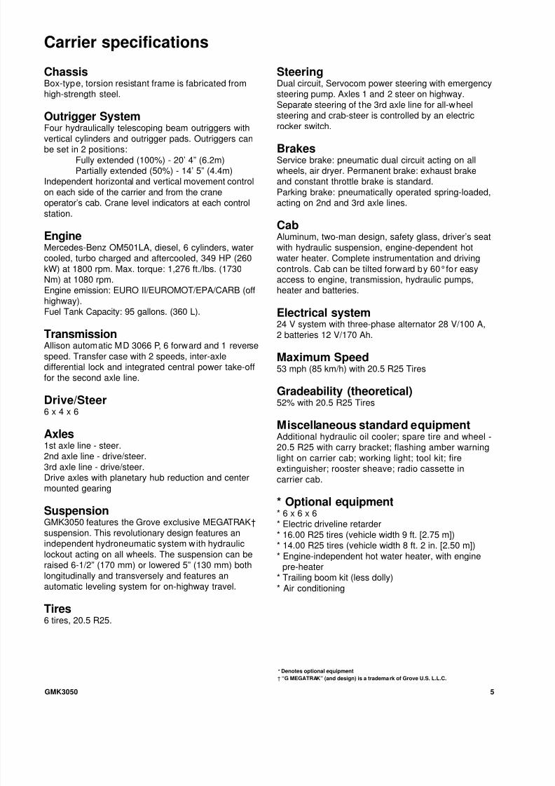
ChassisBox-type, torsion resistant frame is fabricated fromhigh-strength steel.
Outrigger SystemFour hydraulically telescoping beam outriggers with
vertical cylinders and outrigger pads. Outriggers canbe set in 2 positions:
Fully extended (100%) - 20’ 4” (6.2m)Partially extended (50%) - 14’ 5” (4.4m)
Independent horizontal and vertical movement control
on each side of the carrier and from the craneoperator’s cab. Crane level indicators at each control
station.
EngineMercedes-Benz OM501LA, diesel, 6 cylinders, watercooled, turbo charged and aftercooled, 349 HP (260
kW) at 1800 rpm. Max. torque: 1,276 ft./lbs. (1730Nm) at 1080 rpm.Engine emission: EURO II/EUROMOT/EPA/CARB (off
highway).Fuel Tank Capacity: 95 gallons. (360 L).
TransmissionAllison automatic MD 3066 P, 6 forward and 1 reverse
speed. Transfer case with 2 speeds, inter-axledifferential lock and integrated central power take-off
for the second axle line.
Drive/Steer6 x 4 x 6
Axles1st axle line - steer.2nd axle line - drive/steer.
3rd axle line - drive/steer.Drive axles with planetary hub reduction and centermounted gearing
SuspensionGMK3050 features the Grove exclusive MEGATRAK†
suspension. This revolutionary design features an
independent hydroneumatic system with hydrauliclockout acting on all wheels. The suspension can beraised 6-1/2” (170 mm) or lowered 5” (130 mm) both
longitudinally and transversely and features anautomatic leveling system for on-highway travel.
Tires6 tires, 20.5 R25.
SteeringDual circuit, Servocom power steering with emergencysteering pump. Axles 1 and 2 steer on highway.
Separate steering of the 3rd axle line for all-wheelsteering and crab-steer is controlled by an electric
rocker switch.
BrakesService brake: pneumatic dual circuit acting on allwheels, air dryer. Permanent brake: exhaust brakeand constant throttle brake is standard.
Parking brake: pneumatically operated spring-loaded,acting on 2nd and 3rd axle lines.
CabAluminum, two-man design, safety glass, driver’s seat
with hydraulic suspension, engine-dependent hotwater heater. Complete instrumentation and driving
controls. Cab can be tilted forward by 60°for easyaccess to engine, transmission, hydraulic pumps,heater and batteries.
Electrical system24 V system with three-phase alternator 28 V/100 A,
2 batteries 12 V/170 Ah.
Maximum Speed53 mph (85 km/h) with 20.5 R25 Tires
Gradeability (theoretical)52% with 20.5 R25 Tires
Miscellaneous standard equipmentAdditional hydraulic oil cooler; spare tire and wheel -20.5 R25 with carry bracket; flashing amber warning
light on carrier cab; working light; tool kit; fireextinguisher; rooster sheave; radio cassette in
carrier cab.
* Optional equipment* 6 x 6 x 6* Electric driveline retarder
* 16.00 R25 tires (vehicle width 9 ft. [2.75 m])
* 14.00 R25 tires (vehicle width 8 ft. 2 in. [2.50 m])* Engine-independent hot water heater, with engine
pre-heater* Trailing boom kit (less dolly)
* Air conditioning
Carrier specifications
* Denotes optional equipment
† “G MEGATRAK” (and design) is a tradema rk of Grove U.S. L.L.C.

8/8/2019 50tonne Crane Load Chart
http://slidepdf.com/reader/full/50tonne-crane-load-chart 6/13GMK30506
THIS CHART ISONLY A GUIDE AND SHOULD NOT BE USED TO OPERATE THE CRANE. The ind ividual crane's l oad chart, operating i nstructio ns and other instruct ional plates must be r ead and understood pri or to operati ng the cr ane.
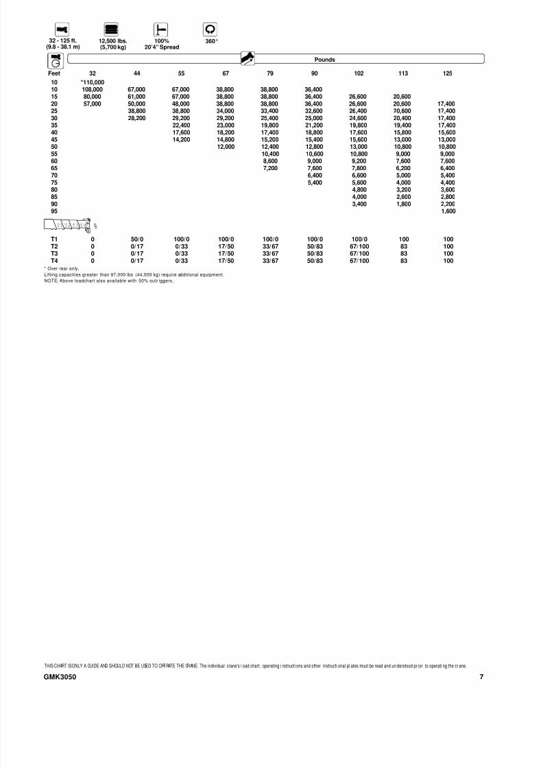
* Over rear only.
Lifting capacities greater than 97,000 lbs (44,000 kg) require additional equipment.
NOTE: Above loadchart also available with 50% outriggers.
Pounds
Feet 32 44 55 67 79 90 102 113 125
10 *110,000
10 108,000 67,000 67,000 38,800 38,800 36,400
15 81,000 61,000 67,000 38,800 38,800 36,400 26,600 20,600
20 61,000 50,000 56,000 38,800 38,800 36,400 26,600 20,600 17,400
25 42,000 43,800 38,800 37,600 34,600 26,400 20,600 17,400
30 35,200 36,400 33,000 32,800 30,000 24,600 20,400 17,400
35 28,200 26,200 26,200 26,000 22,400 20,200 17,400
40 22,600 23,200 21,000 21,400 20,400 20,000 17,20045 18,600 19,200 17,000 17,600 17,800 17,800 16,800
50 16,200 14,600 16,000 15,000 15,200 15,200
55 13,600 14,400 13,400 13,000 13,000
60 12,000 12,400 12,400 11,000 11,200
65 10,400 10,600 10,800 9,200 9,600
70 9,200 9,400 7,800 8,200
75 8,000 8,200 6,600 7,000
80 7,200 5,600 6,000
85 6,400 4,800 5,000
90 5,600 4,000 4,200
95 3,400 3,600
100 3,000
105 2,400
110 2,000
32 - 125 ft.(9.8 - 38.1 m)
23,150 lbs.(10,500 kg)
100%20’4” Spread
360°
T1 0 50/0 100/0 100/0 100/0 100/0 100/0 100 100
T2 0 0/17 0/33 17/50 33/67 50/83 67/100 83 100T3 0 0/17 0/33 17/50 33/67 50/83 67/100 83 100T4 0 0/17 0/33 17/50 33/67 50/83 67/100 83 100
T1 T2 T3 T4 %
* Over rear only.
Lifting capacities greater than 97,000 lbs (44,000 kg) require additional equipment.
NOTE: Above loadchart also available with 50% outriggers.
Pounds
Feet 32 44 55 67 79 90 102 113 125
10 *110,000
10 108,000 67,000 67,000 38,800 38,800 36,400
15 81,000 61,000 67,000 38,800 38,800 36,400 26,600 20,600
20 58,000 50,000 52,000 38,800 38,800 36,400 26,600 20,600 17,400
25 38,800 38,800 36,400 35,800 34,600 26,400 20,600 17,400
30 30,000 31,200 29,200 27,400 27,000 24,600 20,400 17,400
35 24,000 24,600 21,600 21,600 21,400 20,200 17,400
40 19,200 19,600 17,400 19,400 17,600 17,200 17,000
45 15,400 16,000 16,000 16,800 16,000 14,400 14,200
50 13,200 13,600 14,000 14,200 12,000 12,000
55 11,400 11,800 12,000 10,200 10,200
60 9,600 10,000 10,200 8,400 8,600
65 8,000 8,400 8,600 7,000 7,200
70 7,200 7,400 5,800 6,000
75 6,200 6,400 4,800 5,000
80 5,400 3,800 4,200
85 4,600 3,200 3,400
90 4,000 2,400 2,800
95 1,800 2,200100 1,600
32 - 125 ft.(9.8 - 38.1 m)
15,400 lbs.(7,000 kg)
100%20’4” Spread
360°
T1 0 50/0 100/0 100/0 100/0 100/0 100/0 100 100T2 0 0/17 0/33 17/50 33/67 50/83 67/100 83 100T3 0 0/17 0/33 17/50 33/67 50/83 67/100 83 100T4 0 0/17 0/33 17/50 33/67 50/83 67/100 83 100
T1 T2 T3 T4 %
8/8/2019 50tonne Crane Load Chart
http://slidepdf.com/reader/full/50tonne-crane-load-chart 7/137GMK3050
THIS CHART ISONLY A GUIDE AND SHOULD NOT BE USED TO OPERATE THE CRANE. The individual crane's l oad chart, operating i nstructi ons and other instructi onal pl ates must be read and un derstood pr ior to operati ng the cr ane.
* Over rear only.
Lifting capacities greater than 97,000 lbs (44,000 kg) require additional equipment.
NOTE: Above loadchart also available with 50% outr iggers.
Pounds
Feet 32 44 55 67 79 90 102 113 125
10 *110,000
10 108,000 67,000 67,000 38,800 38,800 36,400
15 80,000 61,000 67,000 38,800 38,800 36,400 26,600 20,600
20 57,000 50,000 48,000 38,800 38,800 36,400 26,600 20,600 17,400
25 38,800 38,800 34,000 33,400 32,600 26,400 20,600 17,400
30 28,200 29,200 29,200 25,400 25,000 24,600 20,400 17,400
35 22,400 23,000 19,800 21,200 19,800 19,400 17,400
40 17,600 18,200 17,400 18,800 17,600 15,800 15,60045 14,200 14,800 15,200 15,400 15,600 13,000 13,000
50 12,000 12,400 12,800 13,000 10,800 10,800
55 10,400 10,600 10,800 9,000 9,000
60 8,600 9,000 9,200 7,600 7,600
65 7,200 7,600 7,800 6,200 6,400
70 6,400 6,600 5,000 5,400
75 5,400 5,600 4,000 4,400
80 4,800 3,200 3,600
85 4,000 2,600 2,800
90 3,400 1,800 2,200
95 1,600
32 - 125 ft.(9.8 - 38.1 m)
12,500 lbs.(5,700 kg)
100%20’4” Spread
360°
T1 0 50/0 100/0 100/0 100/0 100/0 100/0 100 100T2 0 0/17 0/33 17/50 33/67 50/83 67/100 83 100T3 0 0/17 0/33 17/50 33/67 50/83 67/100 83 100T4 0 0/17 0/33 17/50 33/67 50/83 67/100 83 100
T 1 T 2 T 3 T 4 %

8/8/2019 50tonne Crane Load Chart
http://slidepdf.com/reader/full/50tonne-crane-load-chart 8/13GMK30508
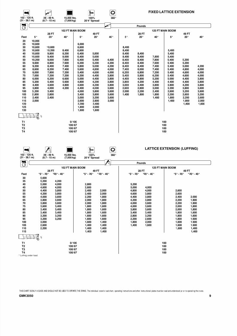
Pounds
102 FT MAIN BOOM 125 FT MAIN BOOM
28 FT 49 FT 28 FT 49 FT
Feet *5°- 20° *20°- 40° *5°- 20° *20°- 40° *5°- 20° *20°- 40° *5°- 20° *20°- 40°30 5,600
35 5,200 4,200
40 5,000 4,000 2,800 5,200
45 4,600 4,000 2,600 5,000 4,000
50 4,400 3,800 2,400 2,000 4,800 4,000 2,600
55 4,200 3,800 2,400 2,000 4,600 3,800 2,600
60 4,000 3,600 2,200 1,800 4,400 3,800 2,400 2,000
65 3,800 3,600 2,000 1,800 4,200 3,800 2,200 1,800
70 3,800 3,600 2,000 1,800 4,000 3,600 2,200 1,800
75 3,600 3,400 1,800 1,600 4,000 3,600 2,000 1,800
80 3,400 3,400 1,800 1,600 3,800 3,600 2,000 1,800
85 3,400 3,400 1,800 1,600 3,600 3,400 1,800 1,600
90 3,200 3,200 1,600 1,600 3,600 3,400 1,800 1,600
95 3,200 3,200 1,600 1,600 3,400 3,400 1,800 1,600
100 3,000 1,600 1,400 3,000 3,200 1,600 1,600
105 3,000 1,400 1,400 2,600 2,800 1,600 1,600
110 2,800 1,400 1,400 2,000 2,200 1,600 1,400
115 1,400 1,400 1,600 1,600 1,400
120 1,400 1,400
125 1,400
130 1,400
THIS CHART ISONLY A GUIDE AND SHOULD NOT BE USED TO OPERATE THE CRANE. The individual crane's l oad chart, operating i nstructi ons and other instru ctional plates must be r ead and understood pri or to operati ng the cr ane.
Pounds
102 FT MAIN BOOM 125 FT MAIN BOOM
28 FT 49 FT 28 FT 49 FT
Feet 5° 20° 40° 5° 20° 40° 5° 20° 40° 5° 20° 40°
20 10,000
25 10,600 6,000
30 10,600 10,600 6,600 8,400
35 10,600 10,200 8,400 6,600 8,400 5,400
40 10,600 9,800 8,200 6,400 5,800 8,400 8,400 5,400
45 10,600 9,400 8,000 6,400 5,600 8,400 8,400 7,800 5,400
50 10,200 9,000 7,800 6,400 5,400 4,400 8,400 8,400 7,800 5,400 5,200
55 9,600 8,800 7,600 6,200 5,200 4,200 8,400 8,400 7,600 5,400 5,200
60 9,200 8,400 7,400 5,800 5,000 4,200 8,400 8,400 7,400 5,400 5,000 4,200
65 8,600 8,200 7,400 5,600 4,800 4,000 8,400 8,400 7,400 5,400 4,800 4,000
70 8,200 7,800 7,200 5,400 4,600 4,000 8,400 8,200 7,200 5,400 4,600 4,000
75 7,800 7,600 7,200 5,200 4,400 3,800 7,400 7,800 7,200 5,400 4,600 4,000
80 7,400 7,200 7,000 5,000 4,400 3,800 6,400 6,800 7,200 5,200 4,400 3,800
85 6,800 7,000 6,800 4,800 4,200 3,800 5,600 5,800 6,200 5,000 4,400 3,800
90 6,000 6,200 6,400 4,600 4,200 3,800 4,800 5,000 5,200 4,800 4,200 3,800
95 5,400 5,400 5,600 4,600 4,000 3,600 4,000 4,200 4,400 4,800 4,200 3,600
100 4,600 4,800 4,200 4,000 3,600 3,400 3,600 3,800 4,000 4,000 3,600
105 4,000 4,200 4,200 3,800 3,600 2,800 3,000 3,200 3,600 4,000 3,600
110 3,600 3,600 4,000 3,800 3,600 2,200 2,400 2,600 3,000 3,400 3,600
115 3,200 3,800 3,600 3,600 1,800 2,000 2,600 3,000 3,200
120 3,400 3,600 2,200 2,400 2,800
125 3,000 3,200 2,000 2,200
130 2,600 2,600 1,600 1,800
135 2,200
102 - 125 ft.(31 - 38.1 m)
28 - 49 ft.(8.7 - 15 m)
23,100 lbs.(10,500 kg)
100%20’4” Spread
360°
102 - 125 ft.(31 - 38.1 m)
28 - 49 ft.(8.7 - 15 m)
23,100 lbs.(10,500 kg)
100%20’4” Spread
360°
T1 0/100 100T2 100/67 100T3 100/67 100T4 100/67 100
T1 T2 T3 T4 %
* Luffing under load.
T1 0/100 100T2 100/67 100T3 100/67 100T4 100/67 100
T1 T2 T3 T4 %
FIXED LATTICE EXTENSION
LATTICE EXTENSION (LUFFING)
8/8/2019 50tonne Crane Load Chart
http://slidepdf.com/reader/full/50tonne-crane-load-chart 9/13
102 FT MAIN BOOM 125 FT MAIN BOOM
28 FT 49 FT 28 FT 49 FT
Feet *5°- 20° *20°- 40° *5°- 20° *20°- 40° *5°- 20° *20°- 40° *5°- 20° *20°- 40°30 5,600
35 5,200 4,200
40 5,000 4,000 2,800 5,200
45 4,600 4,000 2,600 5,000 4,000
50 4,400 3,800 2,400 2,000 4,800 4,000 2,600
55 4,200 3,800 2,400 2,000 4,600 3,800 2,600
60 4,000 3,600 2,200 1,800 4,400 3,800 2,400 2,000
65 3,800 3,600 2,000 1,800 4,200 3,800 2,200 1,800
70 3,800 3,600 2,000 1,800 4,000 3,600 2,200 1,800
75 3,600 3,400 1,800 1,600 4,000 3,600 2,000 1,800
80 3,400 3,400 1,800 1,600 3,800 3,600 2,000 1,800
85 3,400 3,400 1,800 1,600 3,400 3,400 1,800 1,600
90 3,200 3,200 1,600 1,600 2,800 3,200 1,800 1,600
95 3,200 3,200 1,600 1,600 2,200 2,600 1,800 1,600
100 3,000 1,600 1,400 1,800 2,000 1,600 1,600
105 2,600 1,400 1,400 1,400 1,600 1,600 1,600
110 2,200 1,400 1,400 1,600 1,400
115 1,400 1,400 1,400
102 FT MAIN BOOM 125 FT MAIN BOOM
28 FT 49 FT 28 FT 49 FT
Feet 5° 20° 40° 5° 20° 40° 5° 20° 40° 5° 20° 40°
20 10,000
25 10,600 6,000
30 10,600 10,600 6,600 8,400
35 10,600 10,200 8,400 6,600 8,400 5,400
40 10,600 9,800 8,200 6,400 5,800 8,400 8,400 5,400
45 10,600 9,400 8,000 6,400 5,600 8,400 8,400 7,800 5,400
50 10,200 9,000 7,800 6,400 5,400 4,400 8,400 8,400 7,800 5,400 5,200
55 9,600 8,800 7,600 6,200 5,200 4,200 8,400 8,400 7,600 5,400 5,200
60 9,200 8,400 7,400 5,800 5,000 4,200 8,400 8,400 7,400 5,400 5,000 4,200
65 8,600 8,200 7,400 5,600 4,800 4,000 7,400 8,000 7,400 5,400 4,800 4,000
70 8,000 7,800 7,200 5,400 4,600 4,000 6,200 6,800 7,200 5,400 4,600 4,000
75 7,000 7,200 7,200 5,200 4,400 3,800 5,400 5,800 6,200 5,400 4,600 4,000
80 6,000 6,200 6,600 5,000 4,400 3,800 4,400 4,800 5,200 5,000 4,400 3,800
85 5,200 5,400 5,600 4,800 4,200 3,800 3,800 4,200 4,400 4,400 4,400 3,800
90 4,400 4,600 4,800 4,600 4,200 3,800 3,000 3,400 3,800 3,800 4,200 3,800
95 3,800 4,000 4,200 4,400 4,000 3,600 2,600 2,800 3,000 3,200 3,800 3,600
100 3,200 3,400 4,000 3,800 3,600 2,000 2,200 2,400 2,600 3,200 3,600
105 2,800 2,800 3,400 3,800 3,600 1,400 1,800 1,800 2,200 2,600 3,200
110 2,400 2,400 3,000 3,200 3,600 1,400 1,800 2,200 2,600
115 2,000 2,600 2,800 3,000 1,400 1,800 2,000
120 2,200 2,400 1,400 1,600
125 1,800 2,000
130 1,600 1,600
9GMK3050
Pounds
THIS CHART ISONLY A GUIDE AND SHOULD NOT BE USED TO OPERATE THE CRANE. The individual crane's l oad chart, operating i nstructi ons and other instru ctional plates must be r ead and understood pri or to operati ng the cr ane.
Pounds
102 - 125 ft.(31 - 38.1 m)
28 - 49 ft.(8.7 - 15 m)
15,400 lbs.(7,000 kg)
100%20’4” Spread
360°
102 - 125 ft.(31 - 38.1 m)
28 - 49 ft.(8.7 - 15 m)
15,400 lbs.(7,000 kg)
100%20’4” Spread
360°
T1 0/100 100T2 100/67 100T3 100/67 100T4 100/67 100
T1 T2 T3 T4 %
* Luffing under load.
T1 0/100 100T2 100/67 100T3 100/67 100T4 100/67 100
T1 T2 T3 T4 %
FIXED LATTICE EXTENSION
LATTICE EXTENSION (LUFFING)

8/8/2019 50tonne Crane Load Chart
http://slidepdf.com/reader/full/50tonne-crane-load-chart 10/13
102 FT MAIN BOOM 125 FT MAIN BOOM
28 FT 49 FT 28 FT 49 FT
Feet 5° 20° 40° 5° 20° 40° 5° 20° 40° 5° 20° 40°
20 10,000
25 10,600 6,000
30 10,600 10,600 6,600 8,400
35 10,600 10,200 8,400 6,600 8,400 5,400
40 10,600 9,800 8,200 6,400 5,800 8,400 8,400 5,400
45 10,600 9,400 8,000 6,400 5,600 8,400 8,400 7,800 5,400
50 10,200 9,000 7,800 6,400 5,400 4,400 8,400 8,400 7,800 5,400 5,200
55 9,600 8,800 7,600 6,200 5,200 4,200 8,400 8,400 7,600 5,400 5,200
60 9,200 8,400 7,400 5,800 5,000 4,200 7,600 8,200 7,400 5,400 5,000 4,200
65 8,400 8,200 7,400 5,600 4,800 4,000 6,400 7,000 7,400 5,400 4,800 4,000
70 7,200 7,600 7,200 5,400 4,600 4,000 5,400 6,000 6,400 5,400 4,600 4,000
75 6,200 6,600 6,800 5,200 4,400 3,800 4,600 5,000 5,400 5,200 4,600 4,000
80 5,400 5,600 5,800 5,000 4,400 3,800 3,800 4,200 4,600 4,400 4,400 3,800
85 4,600 4,800 5,000 4,800 4,200 3,800 3,000 3,400 3,800 3,600 4,400 3,800
90 3,800 4,000 4,200 4,600 4,000 3,800 2,400 2,800 3,000 3,000 3,800 3,800
95 3,200 3,400 3,600 4,000 4,000 3,600 1,800 2,200 2,400 2,600 3,200 3,600
100 2,800 3,000 3,400 3,800 3,600 1,400 1,600 1,800 2,000 2,600 3,200
105 2,200 2,400 3,000 3,200 3,600 1,400 1,600 2,000 2,600
110 1,800 2,000 2,600 2,800 3,000 1,600 2,000
115 1,400 2,200 2,400 2,600 1,600
120 1,800 2,000
125 1,400 1,600
GMK305010
Pounds
102 FT MAIN BOOM 125 FT MAIN BOOM
28 FT 49 FT 28 FT 49 FT
Feet *5°- 20° *20°- 40° *5°- 20° *20°- 40° *5°- 20° *20°- 40° *5°- 20° *20°- 40°30 5,600
35 5,200 4,200
40 5,000 4,000 2,800 5,200
45 4,600 4,000 2,600 5,000 4,000
50 4,400 3,800 2,400 2,000 4,800 4,000 2,600
55 4,200 3,800 2,400 2,000 4,600 3,800 2,600
60 4,000 3,600 2,200 1,800 4,400 3,800 2,400 2,000
65 3,800 3,600 2,000 1,800 4,200 3,800 2,200 1,800
70 3,800 3,600 2,000 1,800 4,000 3,600 2,200 1,800
75 3,600 3,400 1,800 1,600 4,000 3,600 2,000 1,800
80 3,400 3,400 1,800 1,600 3,400 3,600 2,000 1,800
85 3,400 3,400 1,800 1,600 2,800 3,200 1,800 1,600
90 3,200 3,200 1,600 1,600 2,200 2,600 1,800 1,600
95 3,000 3,200 1,600 1,600 1,800 2,000 1,800 1,600
100 2,600 1,600 1,400 1,600 1,600 1,600
105 2,000 1,400 1,400 1,400 1,600
110 1,800 1,400 1,400 1,400
115 1,400 1,400
THIS CHART ISONLY A GUIDE AND SHOULD NOT BE USED TO OPERATE THE CRANE. The individual crane's l oad chart, operating i nstructi ons and other instru ctional plates must be r ead and understood pri or to operati ng the cr ane.
Pounds
102 - 125 ft.(31 - 38.1 m)
28 - 49 ft.(8.7 - 15 m)
12,500 lbs.(5,700 kg)
100%20’4” Spread
360°
102 - 125 ft.(31 - 38.1 m)
28 - 49 ft.(8.7 - 15 m)
12,500 lbs.(5,700 kg)
100%20’4” Spread
360°
T1 0/100 100T2 100/67 100T3 100/67 100T4 100/67 100
T1 T2 T3 T4 %
* Luffing under load.
T1 0/100 100T2 100/67 100T3 100/67 100T4 100/67 100
T1 T2 T3 T4 %
FIXED LATTICE EXTENSION
LATTICE EXTENSION (LUFFING)

8/8/2019 50tonne Crane Load Chart
http://slidepdf.com/reader/full/50tonne-crane-load-chart 11/1311GMK3050
THIS CHART ISONLY A GUIDE AND SHOULD NOT BE USED TO OPERATE THE CRANE. The ind ividual crane's l oad chart, operating i nstructio ns and other instruct ional plates must be r ead and understood pri or to operati ng the cr ane.
* Over rear only.
Pounds
Feet 32 - 44 FT 44 - 55 FT
10 25,400 26,400
15 17,400 18,400
20 12,200 13,200
25 8,800 9,800
30 6,200 7,400
35 5,400
40 4,000
45 2,600
32 - 55 ft.(9.8 - 13.4 m)
23,100 lbs.(10,500 kg)
Over Rear
T1 0 0T2 0/17 17/33T3 0/17 17/33T4 0/17 17/33
T1 T2 T3 T4 %
* Over rear only.
Pounds
Feet 32 - 44 FT 44 - 55 FT
10 24,200 25,200
15 16,400 17,600
20 11,400 12,600
25 8,200 9,200
30 5,600 6,800
35 5,000
40 3,600
45 2,400
32 - 55 ft.(9.8 - 13.4 m)
15,400 lbs.(7,000 kg)
Over Rear
T1 0 0T2 0/17 17/33T3 0/17 17/33T4 0/17 17/33
T1 T2 T3 T4 %
* Over rear only.
Pounds
Feet 32 - 44 FT 44 - 55 FT
10 23,800 24,800
15 16,200 17,200
20 11,200 12,400
25 8,000 9,000
30 5,400 6,600
35 4,800
40 3,400
45 2,200
32 - 55 ft.(9.8 - 13.4 m)
12,500 lbs.(5,700 kg)
Over Rear
T1 0 0T2 0/17 17/33T3 0/17 17/33T4 0/17 17/33
T1 T2 T3 T4 %

8/8/2019 50tonne Crane Load Chart
http://slidepdf.com/reader/full/50tonne-crane-load-chart 12/13

8/8/2019 50tonne Crane Load Chart
http://slidepdf.com/reader/full/50tonne-crane-load-chart 13/13
Distributed By:
Constant improvement and engineering progress make it necessary that wereserve the right to make specification, equipment, and price changes withoutnotice. Illustrations shown may include optional equipment and accessories andmay not include all standard equipment.
Form No.: GMK3050 Part No.: 3-1309 799-10M Printed in U.S.A.
Grove Worldwide –World Headquarters
Grove U.S. L.L.C.1565 Buchanan Trail EastP.O. Box 21Shady Grove, Pennsylvania 17256, U.S.A.Tel: [Int + 1] (717) 597-8121Fax: [Int + 1] (717) 597-4062Western Hemisphere
Grove Europe Limited*Sunderland SR4 6TT, EnglandTel: [Int + 44] 191 565-6281Fax: [Int + 44] 191 564-0442Europe, Africa, Middle East, Asia/Pacific
Grove Europe Limited*Telford Road, BicesterOxfordshire, OX6 0TZTel: [Int + 44] 1869 878-890Fax: [Int + 44] 1869 878-891*Grove Europe Limited, Registered in England,
Number 1845128, Registered office, Crown Works,
Pallion, Sunderland, Tyne & Wear, England SR4 6TT
Deutsche Grove GmbHSales and ServiceHelmholtzstrasse 12, Postfach 5026D-40750 Langenfeld, GermanyTel: [Int + 49] (2173) 8909-0Fax: [Int + 49] (2173) 8909-30
Wilhelmshaven WorksIndustriegelande West, Postfach 1853D-26358 Wilhelmshaven, GermanyTel: [Int + 49] (4421) 294-0Fax: [Int + 49] (4421) 294-301
Grove France S.A.16, chaussée Jules-César, 95520 OSNY
B.P. 203, 95523 CERGY PONTOISE CEDEXFranceTel: [Int + 33] (1) 30313150Int: [Int + 33] (1) 30386085
Grove Asia/Pacific - Regional Office171 Chin Swee RoadSan CentreSingapore 0316Tel: [Int + 65] 536-6112Fax: [Int + 65] 536-6119Asia/Pacific, Near East
Grove China - Representative OfficeRoom 713, Towercrest PlazaNo. 3 Mai Zi Dian West RoadChao Yang DistrictBeijing, China 100016Tel: [Int + 86] (10) 64 67 16 90Fax: [Int + 86] (10) 64 67 16 91
Grove Product SupportWestern Hemisphere1086 Wayne AvenueChambersburg, Pennsylvania USATel: [Int + 1] (717) 263-5100Fax: [Int + 1] (717) 267-0404
Europe, Africa, Middle East, Asia/PacificSunderland SR4 6TT, EnglandTel: [Int + 44] 191 565-6281Parts Fax: [Int + 44] 191 510-9242Service Fax: [Int + 44] 191 510-9560
http://www.groveworldwide.com