500 Shell Design
28
Chevron Corporation 500-1 July 2000 500 Shell Design Abstract This section of the manual addresses the basic design requirements for atmospheric storage tanks. Company and industry specifications are discussed as well as the data required before sizing and designing a new tank. Information is provided concerning the impact of seismic and wind forces on the design of tanks. It also provides tank construction techniques for keeping the tank within the tolerances of Company and industry specifications. Contents Page 510 Shell Design 500-2 511 Atmospheric Pressure Tanks 512 Internal Pressure Tanks 520 Material Selection 500-9 521 Brittle Fracture 522 Steel Selection Method 530 Seismic and Wind Design 500-12 531 Seismic Design for Tanks 532 Wind Design 540 Shell Construction 500-24 541 Plate Preparation and Shop Inspection 542 Leveling 543 Welding 544 Wind Girders and Preventing Wind Damage During Erection 545 Dimensional Checks During Erection 550 Shell Repairs 500-27
-
Upload
okondu-chiedu -
Category
Documents
-
view
2.075 -
download
6
Transcript of 500 Shell Design

500 Shell Design
AbstractThis section of the manual addresses the basic design requirements for atmospheric storage tanks. Company and industry specifications are discussed as well as the data required before sizing and designing a new tank. Information is provided concerning the impact of seismic and wind forces on the design of tanks. It also provides tank construction techniques for keeping the tank within the tolerances of Company and industry specifications.
Contents Page
510 Shell Design 500-2
511 Atmospheric Pressure Tanks
512 Internal Pressure Tanks
520 Material Selection 500-9
521 Brittle Fracture
522 Steel Selection Method
530 Seismic and Wind Design 500-12
531 Seismic Design for Tanks
532 Wind Design
540 Shell Construction 500-24
541 Plate Preparation and Shop Inspection
542 Leveling
543 Welding
544 Wind Girders and Preventing Wind Damage During Erection
545 Dimensional Checks During Erection
550 Shell Repairs 500-27
Chevron Corporation 500-1 July 2000

500 Shell Design Tank Manual
tions 0.
for
k-g upon at is of and
ior ted e
when
is l
. ure
0-2. p-icker
ced
its
510 Shell DesignThis section covers the basic shell design requirements for:
• atmospheric pressure and
• internal pressure (up to 2.5 psig) tanks.
Use of the Company and Industry Specifications is discussed. Design considerafor low pressure (up to 15 psig) and fiberglass tanks are covered in Section 120
511 Atmospheric Pressure TanksShell design of flat-bottomed storage tanks is discussed, including 1) methods calculating shell plate thickness and 2) design of shell openings.
Shell Plate ThicknessThe principal calculation for the shell's mechanical design is minimum plate thicness required for each successive shell course. The hydrostatic pressure actineach shell course and the diameter of the tank determine the plate thickness threquired for the strength of the steel plate being used. Other important aspectstank shell design are resistance to buckling under wind loads (see Section 530)openings in the shell.
API 650 requires that vertical and horizontal joints between shell plates be buttwelded with full penetration and complete fusion, as shown in Figure 500-1. (Prto 1979, horizontal joints for shell plates greater than 3/8 inch thick were permitto be double welded with 2/3 penetration.) The weld joint efficiency is taken to b100% of the allowable design stress of the grade of plate material being used, the welding procedure is properly qualified in accordance with Section 7 of API 650.
Design Calculations for Shell ThicknessAPI 650 gives two methods for calculating the required plate thickness for eachshell course: the “one-foot method,” and the “variable design point method.” Thsection discusses these two methods in addition to an optional design for smaltanks.
One-Foot Method. This method (API 650, Paragraph 3.6.3) is the simpler to useThe thickness calculated for each shell course is based on the hydrostatic pressone foot above its lower circumferential seam (i.e., the bottom of the tank or thecircumferential seam with the next lower shell course), as illustrated in Figure 50This method shall not be used for tanks larger than 200 ft. in diameter. An assumtion is made that each shell course is stiffened either by the tank bottom or the thshell course immediately below. Therefore, in effect, each shell course is reinforat its lower circumferential seam, and the maximum stress that occurs in a shellcourse is shifted above the circumferential seam. The distance that the maximumstress is shifted is conservatively set at one foot, which gives the design methodname.
July 2000 500-2 Chevron Corporation

Tank Manual 500 Shell Design
The maximum allowable design stress that can be used with the one-foot method is 2/3 of the yield strength of the steel being used, with the restriction that the design
Fig. 500-1 Weld Joints in Cylindrical Tank Shell From API 650, Figures 3.1 and 3.2. Courtesy of the American Petro-leum Institute
A) Horizontal (Circumferential) B) Vertical
Fig. 500-2 Schematic of “One-Foot” Method for Cylindrical Tank Shell Design
Chevron Corporation 500-3 July 2000

500 Shell Design Tank Manual
stress cannot exceed 2/5 of the tensile strength These restrictions shall apply to all courses. The lower value shall be used. The restrictions based on tensile strength have the effect of reducing the design stress for each shell course when some steels with tensile strengths above approximately 60,000 psi are used. An element of conservatism is thereby introduced into the critical shell-to-bottom joint when tanks are designed for high stress levels.
Thickness calculations must be made for each shell course for both the specific gravity of the liquid being stored and the hydrostatic test. The formulas in API 650, Paragraph 3.6.3.2 should be used. For hydrostatic test conditions, the maximum allowable design stress that can be used by this method is 3/4 of the yield strength of the steel being used, with the restriction that the design stress cannot exceed 3/7 of the tensile strength. The lower value shall be used.
Basically, these formulas are for the hoop stress in a cylinder under internal pressure, where the hydrostatic pressure one foot above the lowest circumferential seam of a shell course is substituted for the internal pressure. If a tank is being designed for the storage of several alternate liquids, the design calculations should be made for the liquid with the highest specific gravity.
The minimum thickness required for each shell course is the greater of that calculated for 1) the operating conditions and 2) the hydrostatic test conditions. For operating conditions the corrosion allowance is then added to the calculated thickness. No corrosion allowance is added to the thickness calculated for hydrostatic test conditions. Also, a higher stress is allowed for the hydrostatic test (approximately 10%, see Table 3-2, API 650). The operating conditions usually determine the shell thicknesses that are required.
Variable Design Point Method. With this method (API 650, Paragraph 3.6.4) the engineer computes a more exact location for the maximum stress in each shell course by giving consideration to shearing forces at the circumferential seams and consequent elastic deflections. This more complex procedure requires first calculating preliminary shell course thicknesses by use of the one-foot method, to determine the points of maximum stress in each shell course. Similar to the one-foot method, thickness calculations must be made independently for both the design and hydrotest conditions for each shell course, and the greater value is the minimum thickness required.
Thinner shell courses are normally obtained by designing with the variable design point method, which reduces materials and construction costs. Furthermore, this method can permit the design and construction of larger diameter tanks.
The variable design point method has separate design procedures for the first (bottom), second, and upper shell courses. See Appendix K of API 650, which gives an example of the use of the variable design point method for the design of a tank.
July 2000 500-4 Chevron Corporation

Tank Manual 500 Shell Design
e y for
ept
24 s m
ction is e
use. nch for
The thicknesses of the upper shell courses are determined with an iterative procedure that involves:
1. calculating preliminary shell thicknesses using the one-foot method
2. estimating the point of maximum stress in each shell course depending on the relative plate thicknesses of adjoining shell courses
3. calculating a new shell thickness on the basis of the hydrostatic pressure at the estimated point of maximum stress
This sequence of calculations is repeated, substituting the newly calculated shell thicknesses. This process further refines the estimated point of maximum stress until there is no significant change in the calculated plate thickness. Three iterations are usually sufficient. The resulting minimum plate thicknesses for each of the upper shell courses are usually thinner than those calculated with the one-foot method, because the more accurately estimated point of maximum stress in each upper shell course is usually greater than the conservative one-foot assumption.
Optional Design for Small Tanks. Appendix A to API 650 provides a lower cost alternative for the design of small tanks with shell thicknesses no greater than ½ inch including corrosion allowance. The design methodology is essentially thsame as the one-foot method, with two significant exceptions: 1) the maximumallowable design stress that can be used is 21,000 psi; and 2) the joint efficiencvertical welds is reduced to 0.85 or 0.70 due to reduced radiographic inspectionrequirements.
Appendix J to API 650 contains design requirements similar to Appendix A, excthat it specifically applies to shop fabricated tanks no greater than 20 feet in diameter, with no restriction on plate thickness. Radiographic inspection can beeliminated if weld joint efficiency is reduced to 0.70.
API Specification 12D provides for the construction of field welded tanks with acapacity up to 10,000 bbl for the storage of production liquids. These tanks areessentially predesigned for standard dimensions up to 55 feet in diameter and feet high. No separate design calculations are required. API Specification 12F isimilar in concept but applies to standardized shop welded tanks with a maximusize of 15.5 feet in diameter and 24 feet high. The required design and construdetails of these two specifications are minimal, and no radiographic inspection required to verify construction quality. Therefore, these specifications should beused only when the service conditions and location of the tank do not require thsignificantly greater assured reliability obtained by using API 650.
Shell OpeningsAPI Standard 650 provides standardized designs for shell openings (API 650, Paragraph 3.7.5, 3.7.6, and 3.7.7) including manways, nozzles, and flush-type fittings. Figures 3-4A, 3-5, and 3-7 of API 650 show the major design details forthese openings. All essential dimensions (for reinforcement plates, flanges, andwelds etc.) are tabulated in API 650 for the range of opening sizes in common The shell plates for flush-type fitting assemblies are required to be 1/16 to 1/8 ithicker than the adjacent shell plates in the lowest shell course. Other designs
Chevron Corporation 500-5 July 2000

500 Shell Design Tank Manual
nch
manways and nozzles are permitted, if they provide equivalent strength and are agreed to by the tank purchaser. Section 700 discusses the different types of openings and their uses.
Reinforcement and Weld Details. Reinforcement and the weld details of shell openings strongly affect tank reliability. The concept for reinforcement is: the cross-sectional area of the hole cut in the shell must have an equal area of reinforcement around the opening. The cross-sectional area of the hole is measured for the opening’s vertical diameter, and all of the reinforcement must be within twice the vertical diameter of the hole in the shell from the centerline of the opening. The required reinforcement is usually provided by a reinforcing pad, but excess thickness in the tank shell or neck of the fitting can be included in the calculation of reinforcement area. Insert-type reinforcement (i.e., thicker plate butt welded into the shell that provides both the minimum shell thickness and area of reinforcement) can also be used.
Reinforcement of flush-type fittings is especially important, and additional design criteria are given in API 650. The bottom reinforcing plate is particularly critical, because it also serves as the highly stressed shell-to-bottom joint. The required thickness for the bottom reinforcing plate is shown in Table 3-10 of API 650. For nozzles not covered in Table 3-10, a special formula is used to calculate the minimum thickness of the bottom reinforcing plate (see API 650 3.7.7.6). This formula takes the design fill height of the tank into consideration.
API 650 advises that external loads on connections to shell openings should be considered when designing the reinforcement of openings. Appendix P of API 650, Allowable External Load on Tank Shell Openings, can be used to do this. It is preferable to keep external loads, such as those resulting from piping connections, as low as practicable. When significant external loads cannot be avoided, Appendix P requirements should be invoked.
The minimum requirements in API 650 for weld details for shell openings are illustrated in Figure 3-4B of API 650. Most important is that full penetration welds are required to attach the connections to the shell, unless insert-type reinforcement is used. However, reinforcing pads are attached to the shell and fitting neck with fillet welds. It is also important to adhere to the minimum size requirements for all of the welds, to be certain that the connections to the openings have sufficient strength. In addition, the openings should be located such that the periphery of their reinforcing pads are at least 6 inches from any butt welded seams in the shell, or greater where required by API 650 Section 3.7.3. All reinforcing pads welded to plate should be provided with a vent hole for welding.
Small connections should use weld bosses or half couplings per API 650, Figure 3-5.
Thermal Stress Relief. API 650 Section 3.7.4 requires thermal stress relief of
• All flush-type fittings.
• All connections to 12-inch or larger openings in shell plates greater than 1 ithick.
July 2000 500-6 Chevron Corporation

Tank Manual 500 Shell Design
ile
ies ank the ate-
are sign in this d o ss
plift lift
ll-to-rnal
the
mits
ks roof ). e
• All connections requiring reinforcement to openings in shell plates with tensstrengths of 65,000 psi and higher.
This requirement is met by prefabricating and then stress-relieving subassemblcontaining the shell connections in a shop and then butt welding them into the tshell during construction of the tank. Thermal stress relief significantly reduces risk of brittle fracture when service stresses are high and when high strength mrials are used for construction.
Shell JointsWeld joints in the tank shell were shown in Figure 500-1. For discussion of the shell-to-bottom joint, see Section 220; for roof-to-shell joint, Section 420.
512 Internal Pressure Tanks
Small Internal Pressures (up to 2.5 psi)Tanks can be designed for small internal pressures up to 2.5 psi by using the supplemental requirements of Appendix F to API Standard 650. The two majoradditional considerations addressed by Appendix F are the uplift of the tank attributable to the small internal pressure acting on the roof of the tank, and thestrength of the roof-to-shell joint. Figure 500-3 is a schematic of the forces that developed by an internal pressure in a cylindrical tank with a fixed roof. The deformulas used for small internal pressures are based on the forces representedschematic. Calculations are made of the maximum design pressure, the requirearea at the roof-to-shell joint, and the failure pressure of the roof-to-shell joint. Nadditional design calculations for the thickness of shell plates are required, unleanchoring of the tank is provided.
Maximum Internal Design Pressure. The primary criterion for establishing the maximum internal design pressure permitted for a tank is that it cannot cause uat the bottom when the tank is empty (API 650, Appendix F, Paragraph F.4). Upof a tank must be prevented, because it would develop a high stress at the shebottom joint that could cause failure. Therefore, the upward force due to the intepressure acting on the roof of the tank may not exceed the combined weight ofshell and roof. The formula in API 650, Paragraph F.4.2 is an expression of thiscriterion and is used to calculate the maximum design pressure for a tank.
The internal design pressure can be permitted to exceed this maximum designpressure only if anchoring of the tank to the foundation is provided, which also requires increasing the shell thickness above that calculated for the hydrostaticpressure at the design liquid height. However, the Company's specification perusing anchors only with special review of the design and approval.
Roof-to-Shell Joint. Figure F-2 in Appendix F of API 650 illustrates various construction details of the roof-to-shell joint that are permitted to be used for tanwith small internal pressures. This joint must withstand the upward force on thedeveloped at the internal design pressure (API 650, Appendix F, Paragraph F.5However, the force resulting from the internal pressure is counterbalanced by th
Chevron Corporation 500-7 July 2000

500 Shell Design Tank Manual
e ess n
the
weight of the roof. The joint is designed by calculating the total required area at the joint for a maximum stress of 20,000 psi. The formula in Paragraph F.5 of Appendix F, API 650 is used to make this calculation. In the formula ’A’ is the total cross-sectional area at the joint. It includes the portions of the roof and shell crosshatched in Figure F-2, in addition to the compression ring.
Failure Pressure. The roof-to-shell joint is required to have a failure pressure lower than the maximum design pressure (API 650, Appendix F, Paragraph F.6). In this manner, the roof-to-shell joint will fail before uplift of the tank can occur, and failure of the shell-to-bottom joint accompanied by release of the tanks contents is prevented. A roof-to-shell joint meeting this criterion is called a “frangible joint.”
Failure of the roof-to-shell joint is expected to occur when the stress exceeds thyield strength of the material. It is assumed that yielding will occur when the strin the joint reaches 32,000 psi, which is 60% higher than the stress at the desigpressure. The failure pressure is calculated by the formula in Paragraph F.6 of Appendix F of API 650.
For large tanks having roofs with shallow slopes, it is recommended that the maximum design pressure not exceed 80% of the calculated failure pressure. Emergency venting must be provided if the calculated failure pressure exceedsmaximum design pressure.
For a discussion of the shell-to-bottom joint, see Section 220.
Fig. 500-3 Schematic of Forces Developed by an Internal Pressure in a Cylindrical Tank with a Fixed Roof
July 2000 500-8 Chevron Corporation

Tank Manual 500 Shell Design
ability
s.
Low Internal Pressures (up to 15 psi)Refer to Section 1200 and API 620 for design information on low pressure tanks.
520 Material SelectionThe two primary concerns when specifying materials for new tanks are brittle fracture and corrosion. Welding is addressed by Company specifications and API codes. It is important to know the type of fluid, operating temperature, design life, geographic location, and the minimum design metal temperature. The minimum design metal temperature defines which grade of steel is necessary to prevent brittle fracture. The other variables influence the corrosion prevention measures needed to assure a tank meets the design life.
Nearly all tanks are built from carbon steel regardless of the service fluid. Choice of the grade of carbon steel is based entirely upon the necessary impact toughness requirements. This section concentrates on how to choose the steel for the shell. Appurtenances, nozzles, etc., are made of the same grade steel as the shell whenever possible.
521 Brittle Fracture
PrinciplesTanks, like any structures, can fail by brittle or ductile fracture. Brittle fracture describes a tensile failure with the material showing little deformation or yielding. Typically, brittle fractures start at a flaw and are associated with catastrophic failures because the crack grows rapidly and the material has little ability to arrest crack growth. Additional background on brittle fracture can be found in Section 300 of the Corrosion Prevention and Metallurgy Manual. API 653 Section 3 offers a procedure for the assessment of existing tanks with respect to brittle facture.
Ductile failures are preceded by a relatively large amount of deformation and yielding. Ductile fracture is not directly addressed in this section because preventive measures are already incorporated into codes and specifications.
A tank’s susceptibility to fracture is determined by the magnitude of the tensile stress, the size of the flaw, and the metal's fracture toughness (i.e., the metal’s to resist fracture). Tank failures can be avoided by carefully controlling each of these variables.
Avoiding Brittle Fracture in New TanksThe Company's approach to controlling brittle fractures in new tanks is as follow
1. Select the appropriate tank materials. (See Section 522.)
2. Design tanks according to relevant API Codes (API 650).
3. Fabricate tanks according to Company specifications, TAM-EG-967 or TAM-EG-4813 and API codes.
Chevron Corporation 500-9 July 2000

500 Shell Design Tank Manual
nk
n est
at mean
s ll
est here of en
be
be ould
to 6 rcised dly ion
ull
t or
4. Repair, alter or reconstruct tanks to API 653 requirements.
API 650 and API 653 offer some guidance on material selection for tank plate and appurtenances. The Company’s specifications are more stringent than the API documents. Additional instruction is given below for choosing a cost-effective tamaterial with suitable mechanical properties for the intended service.
Brittle Fracture in Existing TanksThe Ashland Oil storage tank failure in January 1988 prompted general concerabout the potential for brittle fracture in other tanks. Existing tanks with the highrisk of brittle fracture include the following:
• Tanks built before the early 1960s (before 1955 if built to EG-967)• Tanks operating below the transition temperature of the steel• Tanks that have been repaired or modified
The primary reason why these tanks are most susceptible to brittle fracture is ththe steel used in these tanks may not have adequate toughness. The observedtransition temperature for normal practice, pre-1960 steel is approximately 50°F. Tanks constructed to TAM-EG-967 conform to improved materials toughness requirements. Tanks from the early 1970s were built to API 650, which includesmaterial toughness requirements.
When repairing or modifying tanks, follow API 653. Most reported brittle fractureoriginated at flaws or notches created by a repair or alteration to the bottom shecourse or to the floor in the vicinity of the bottom shell course. For tanks of highrisk as defined above, it is important to eliminate and avoid notches or cracks wstress concentrations can be excessive. To achieve this may require inspectionprevious repairs and concentration on good design practice in new repairs. WhAPI 653 cannot be followed, follow the guidelines for repairs and modifications listed below.
Manways and Nozzles. Manways and nozzles or other shell penetrations shouldmoved up if the slot for a new bottom cuts into the reinforcing plate. Flush-type clean-outs, flush-type shell connections, and weld spacing requirements shouldaccording to API 650 and API 653 Section 7. Nozzles and reinforcing plates shbe welded with full penetration welds.
Door Sheets. Door sheets should be cut with corners rounded to a radius equal times the plate thickness but in no case less than 2 inches. Care should be exeto ensure that proper weld gaps are possible during the reweld. Do not repeatecut and weld the same door sheet. Do not lap-weld door sheets. See SpecificatTAM-MS-2 for door sheet removal and installation.
Bottom Shell Course Attachments. All clips, brackets, and lugs welded to the bottom shell course should be welded all the way around. All welds should be ffillet.
All welds on the bottom course should be of the highest quality and should meeexceed API 650 and API 653 requirements.
July 2000 500-10 Chevron Corporation

Tank Manual 500 Shell Design
l l has
al lity. d
e r
g
ave n ure h
Ts) elp
t
s per . Cost igh, are st
for
522 Steel Selection MethodThe Company’s practice for selecting steel for tank construction is to use a steeabove its ductile-to-brittle transition temperature. This helps ensure that the steeadequate toughness for the temperature conditions at the specified geographiclocation. A steel’s toughness is a function of temperature, thickness, and its quaFor common tank steels, toughness decreases with decreasing temperature anincreasing thickness.
Detailed guidance on brittle fracture prevention is provided in Section 300 of thCorrosion Prevention and Metallurgy Manual. The basic steps in selecting steel foconstructing tanks and appurtenances are as follows:
1. Define the minimum design metal temperature. The minimum design metal temperature is the lowest 1-day, mean ambient temperature in the locality where the tank is to be installed, plus 15°F (per API 650 Section 2.2.9.3). The “15°F” factor is added by conventional practice and results from recognizinthat it takes a long time for the fluid contents and thus the shell metal temperature to reach the ambient temperature. Many Company locations hestablished standard minimum design metal temperatures, usually found ovessel safety data sheets. To determine a minimum design metal temperatfor Company locations that do not have one, use API 650, Figure 2-2, whicprovides an isothermal map of the lowest 1-day mean temperatures.
2. Determine which steel grades are acceptable with and without impact tests. Use API Standard 650, Figure 2-1 (along with API RP 579) for guidance in selecting steels and establishing minimum design metal temperatures (MDMfor tanks. If the tank material is unknown, then API RP 579 provides some hin that we can consider the tank safe to use at any temperature for metal thicknesses less than 0.5". Also, metal temperatures above 60°F are safe regardless of the thickness. For tanks with metal temperatures less than 60°F, and thicknesses greater than 0.5", contact CRTC’s Materials and EquipmenEngineering Group (MEE) for help. Also contact MEE for help with atmospheric or low pressure tanks dealing with a refrigerated product.
3. Select a steel grade or potential steel grades for the tank and appurtenances. The Company prefers to use a steel with inherent toughnes(steels on the lower curves of Step 2) rather than attempting to buy a cheasteel which then requires impact tests (steels on the upper curve of Step 2)comparisons favor inherently superior steel. The cost of impact testing is hadding a premium of about 10% to the plate cost. Cost ratios of tank steelspresented in Figure 500-4. In the U.S., the premiums charged for the highequality groups (fully killed, fine grain practice and fully killed, fine grain practice and normalizing) are significant; however, premiums can be lower foreign-manufactured steels. When impact tests are required, TAM-EG-967defines the Company’s requirements.
Chevron Corporation 500-11 July 2000

500 Shell Design Tank Manual
In general, unless the fluid to be stored in the tank is highly corrosive, requiring special materials consideration, tanks should be built from ASTM Grade A283 or A131 steel plates. If better low temperature impact properties are desired in the tank materials because of the geographic location, ASTM Grade A516 is a good candidate steel because of its lower transition temperature.
530 Seismic and Wind DesignThis section covers the impact that seismic and wind forces have on a tank and how to design for those forces.
531 Seismic Design for Tanks
Seismic ForcesEarthquake-induced ground motion causes movement of objects supported on the ground. For tanks the resulting lateral forces cause the tank contents to slosh, which creates an overturning moment at the base of the tank. This moment leads to uplift of one side of an unanchored tank and puts high compressive loads on the opposite side of the tank. This highly compressive loading in the shell can cause the lower course of the tank shell (and sometimes the upper courses) to buckle. The unanchored tank, in effect, tries to tip, uplifting on one side, then returning to rest and then possibly tipping in the opposite direction.
Fig. 500-4 A U.S. Producer’s April 1988 Prices for Steel Plates by Quality Grouping
ASTMSpecification(1)
Maximum Thickness, Inch
Cost Relativeto A283C(2)
Rimmed A-36 ½ 1.02
A-283C 1½ 1.00
A-131A ½ 0.84
(A-285C) 1½ 1.09
Semi-Killed A-36 ½ to 1½ 0.49 to 0.93
A-131B 1 0.85
Fully-Killed, FGP A-131C 1½ 0.92
(A-516-70) 1½ 1.18
Normalized A-131C 1.09
(A-516-70) 1.37
(A-537A,C1) 1.16
(1) ASTM numbers in parenthesis are pressure vessel quality steel. Normally not used for tankage except where required for toughness.
(2) A283C was chosen as the base case, so its ratio is 1.00. The ratios are from base prices and do not include many extras, such as odd thickness, tonnage, etc.
July 2000 500-12 Chevron Corporation

Tank Manual 500 Shell Design
e-
of
if
er . e e
n-h of
te plift. t of
is
the ble,
le of
Resistance to tipping is provided by 1) the shell weight, 2) the weight of the tank contents next to the shell and 3) the compressing on the opposite side of the shell by the foundation.
Earthquakes can also damage tanks in these ways:
• Sloshing in full or nearly full tanks can cause floating roofs to ride over the shell resulting in major seal damage; or may damage fixed roofs by impingment of the contents on the roof.
• Torsional rotations of floating roofs can damage the gage well and rolling roladder.
• The uplifting of a tank may damage nozzles and piping attached to the tanksufficient flexibility is not provided in the piping.
Tank ProportioningSeismic design of tanks starts with tank proportioning. A wider, shorter tank (lowheight-to-diameter ratio) has superior tipping resistance over a tall, narrow tankUnanchored tanks will generally be limited to the height-to-diameter ratios in thdifferent seismic zones as shown earlier in Figure 100-1. The seismic zones ardefined in Appendix E of API 650 (also Section 100 of the Civil and Structural Manual).
Tanks with greater height-to-diameter ratios than suggested may require substatially thicker shells to compensate for higher loadings or require anchoring. Botthese options may be impractical to construct.
In addition to proportioning, it is necessary to design a thick enough bottom pla(or annular ring) to optimize the amount of the tank contents which can resist uThe thicker bottom plate will in turn reduce the high local compressive loads thacan cause buckling. The design procedure is thoroughly covered in Appendix EAPI 650.
Seismic Design ProcedureAfter a tank is proportioned, the detailed design of the tank and its componentsnext. The seismic design will affect the following tank components:
• Shell lower course and possibly upper courses• Tank bottom annular ring• Roof columns• Tank attachments
The design procedure is given in Appendix E of API 650. For unanchored tanksdesign procedure in Appendix E will determine whether or not: 1) the tank is sta2) the bottom plate is thick enough, and 3) the shell is thick enough. An exampthe procedure is shown below in Figure 500-5.
Appendix E provides the design seismic load for Seismic Zones 1 through 4.
Chevron Corporation 500-13 July 2000

500 Shell Design Tank Manual
Bottom Plate Thickness. If the tank is not stable, the bottom plate near the tank shell can be thickened to increase the hold-down weight of the tank contents in accordance with the restrictions of API 650 E.4.2. Thickening the bottom plate only near the shell creates an annular ring. The minimum width and thickness of the annular ring is determined in Paragraph E.4.2.
Shell Thickness. It is Company practice to use the new tank steel weight based on actual, installed plate thicknesses in calculating the overturning and resisting moments defined in Paragraphs E.3.1 and E.5.1. The new tank wall thicknesses, less the corrosion allowance, are used only to check shell compression in accordance with Paragraph E.5.3. It is generally more economical to change tank proportions rather than to thicken the tank shell to increase the holddown weight.
Roof column. The roof column design procedure is given in TAM-MS-967.
Fig. 500-5 Seismic Design Example (1 of 4) Derived from API 650, Appendix E. Courtesy of the American Petroleum Institute
This example follows API 650 Appendix E.
Given:
Tank diameter 40 feet
Tank height 24 feet (three 8-foot courses)
Seismic zone 4
Soil Type S3
Tank material A283 Gr C, Fy = 30 ksi
Cone roof weight 20,000 lbs. (50% supported by shell)
Specific gravity 0.95
Corrosion allowance 0.125 inches
Importance factor 1.0
Site factor/coefficient 1.5
Metal thicknesses:
Shell Course 1 and 2 0.25 inches (includes corrosion allowance)
Shell Course 3 0.1875 inches (includes corrosion allowance)
Bottom 0.25 inches (excludes corrosion allowance)
1. Check height-to-diameter ratio (see Figure 100-1). Because H/D = 0.6, the tank probably will not meet seismic requirements. Note: The liquid level is assumed to be the same height as the tank shell in this example.
2. Calculate the overturning moment (M) due to seismic forces applied to the bottom of the shell:
M = ZI(C1WsXs + C1WrHt + C1W1X1 + C2W2X2) (Eq. 500-1)
where:
Z = Zone coefficient = 0.4 for Zone 4
July 2000 500-14 Chevron Corporation

Tank Manual 500 Shell Design
I = Importance factor = 1.0
C1 = Lateral force coefficient = 0.60
Ws = Weight of shell = 28,200 lb
Xs = Height from bottom of shell to center of gravity of shell = 11.3 ft
Wr = Weight of roof supported by shell + weight at snow load speci-fied by owner
= 10,000 lb
Ht = Total height of shell = 24 ft
H = Maximum design liquid level = 24 ft
Wt = Weight of contents = 1,788,000 lb
W1 = Weight of effective mass of tank contents which move in unison with tank shell:For D/H = 1.7, W1/WT = 0.62 W1 = 0.62 WT = 1,108,560 lb
X1 = Height from bottom of tank shell to centroid of lateral force applied to W1:For D/H = 1.7, X1/H = 0.375 X1 = 0.375H = 9 ft
C2 = Lateral force coefficient:k = 0.585 T = kD1/2 = 0.585(40)1/2
S = Site factor)C2 = 0.75 S/T
= 3.70= 1.5= 0.304
W2 = Weight of effective mass:For D/H = 1.7, W2/WT = 0.37W2 = 0.37WT = 661,560 lb
X2 = Height from bottom of tank shell to centroid of lateral force applied by W2:For D/H = 1.7, X2/H = 0.636 X2 = 0.636 H = 15.3 ft
Results:
M = 3,817,000 ft-lb using above figures.
3. Calculate resistance to overturning. wL = Maximum weight of the tank contents which can be used to resist the shell overturning moment.
(Eq. 500-2)
For tb = 0.25 inches
= 1633 lb/ft (see API 650 E.4.1)
Fig. 500-5 Seismic Design Example (2 of 4) Derived from API 650, Appendix E. Courtesy of the American Petroleum Institute
wL 7.9 tb FbyGH =
wL 7.9 .25( ) 30 000,( ) 0.95( ) 24( ) =
Chevron Corporation 500-15 July 2000
500 Shell Design Tank Manual
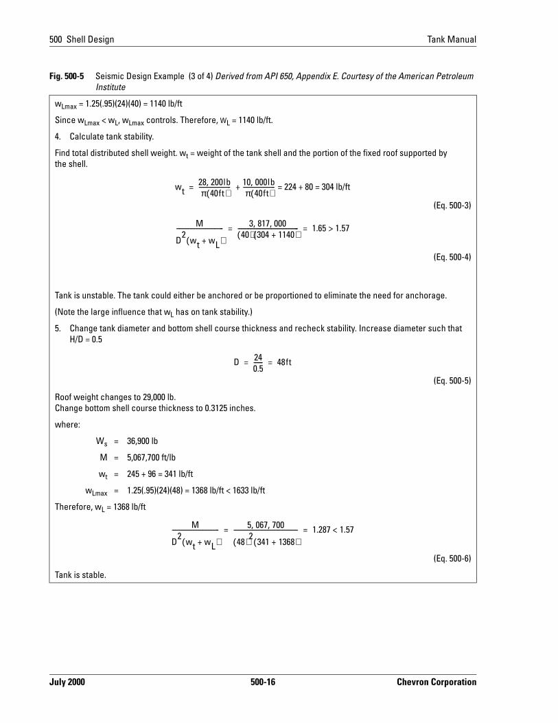
wLmax = 1.25(.95)(24)(40) = 1140 lb/ft
Since wLmax < wL, wLmax controls. Therefore, WL = 1140 lb/ft.
4. Calculate tank stability.
Find total distributed shell weight. wt = weight of the tank shell and the portion of the fixed roof supported by the shell.
(Eq. 500-3)
(Eq. 500-4)
Tank is unstable. The tank could either be anchored or be proportioned to eliminate the need for anchorage.
(Note the large influence that wL has on tank stability.)
5. Change tank diameter and bottom shell course thickness and recheck stability. Increase diameter such that H/D = 0.5
(Eq. 500-5)
Roof weight changes to 29,000 lb.Change bottom shell course thickness to 0.3125 inches.
where:
Ws = 36,900 lb
M = 5,067,700 ft/lb
wt = 245 + 96 = 341 lb/ft
wLmax = 1.25(.95)(24)(48) = 1368 lb/ft < 1633 lb/ft
Therefore, wL = 1368 lb/ft
(Eq. 500-6)
Tank is stable.
Fig. 500-5 Seismic Design Example (3 of 4) Derived from API 650, Appendix E. Courtesy of the American Petroleum Institute
wt28 200lb,π 40ft( )
--------------------- 10 000lb,π 40ft( )
--------------------- = 224 + 80 = 304 lb/ft+=
M
D2
wt wL+( )------------------------------- 3 817 000, ,
40( ) 304 1140+( )---------------------------------------- 1.65 1.57>= =
D 240.5------ 48ft= =
M
D2
wt wL+( )------------------------------- 5 067 700, ,
48( )2341 1368+( )
------------------------------------------ 1.287 1.57<= =
July 2000 500-16 Chevron Corporation

Tank Manual 500 Shell Design
Anchoring TanksFor small tanks (generally up to 4000-bbl capacity) it may be desirable to anchor the tank at its base in order to safely increase the height-to-diameter ratio of the tank. Typically, the tank would be anchored to a concrete ringwall that weighs enough to develop the force in the anchors. Alternatively, uplift piles may be provided to develop the anchor resistance.
6. Check compression in shell (see API 650 E.5.1 Figure E-5)
(Eq. 500-7)
Solving for b,
where:
b = Maximum longitudinal compressive force = 4,780 lb/ft
t = .3125 - .125 = .1875 in. = shell thickness for shell stress design
From API 650 E.5.3:
fa = maximum longitudinal compressive stress
(Eq. 500-8)
(Eq. 500-9)
Therefore:
(Eq. 500-10)
Because fa < Fa, shell thickness is okay.
7. Check next course in accordance with API 650 E.5.4 and the procedure in TAM-MS-967.
8. Check center column in accordance with Section E.8.4 of TAM-MS-967.
9. Check bottom plate thickness to see if annular ring is required. (See API 650 E.4.1) Since this wL (1633 lb/ft) is greater than the limiting wL (1368 lb/ft) the ¼ inch thick bottom is adequate and no annular plate is required.
End of Seismic Design Example
Fig. 500-5 Seismic Design Example (4 of 4) Derived from API 650, Appendix E. Courtesy of the American Petroleum Institute
b wL+
wt wL+------------------- 3.6=
b12t------- 4 780lb,
12 .1875( )---------------------- 2124 lb/in.
2= =
GHD2
t2
-------------- .95( ) 24( ) 48( )2
(.1875)2
----------------------------------- 1.49 106
106
>×= =
Fa10
6t
D---------- 3906 lb/in
22124 lb/in
2>= =
Chevron Corporation 500-17 July 2000

500 Shell Design Tank Manual
k” s than
ould wn
al
41
al ed e re
art to
Anchoring larger tanks (over 4000 bbls) is usually undesirable. The force required to anchor such tanks is very large, requiring a massive ringwall or a very large number of uplift piles. The cost for anchoring may exceed the cost of the tank itself. It may not even be feasible to construct an adequate anchor system. If feasible, anchoring of large tanks should be done only as a last resort where there is insufficient room to provide the storage capacity required with a properly proportioned unanchored tank.
When anchoring a tank, the overturning moment (see API 650 Appendix E for calculations) must be resisted by all components of the anchoring system: the anchor bolts, anchor chairs, foundation, and the soil. Proper seismic design should have sufficient ductility for good performance. The failure mode should be the component that causes the least threat to safety and the least damage to the structure. The anchor bolts, therefore, are typically designed to be the “weak linin the anchorage system; the other components being designed for higher loadthe design forces.
First, so that the bolt yields before the chair or its attachment yields, the chair shbe designed for the bolt yield strength as specified by API 650 E.6.2.1. and shoin the following equation:
(Eq. 500-11)
where:PBY = bolt yield capacity
ABT = tensile stress area of bolt (in2)
= 0.7854(d-0.9742/N)2
d = nominal bolt diameter (in)
N = number of threads per inch
FY = yield tensile stress of bolt material (33000 psi for A-307 materior reinforcing steel (psi)
The bolt must also yield well before the bolt pulls out of the concrete. Section 2and Appendix B in the Civil and Structural Manual presents the requirements for ductile anchor bolt designs in greater detail.
To reduce the concentrated stresses occurring at anchor locations, use individuchairs or a continuous ring. Although continuous rings distribute the concentratstresses better than individual chairs, they must be continuous around the entirtank, which is difficult if there are obstructions. Hence individual anchor chairs amost often used.
Anchor chair and continuous ring designs are covered in AISI E-1, Volume II, PVII, which is referenced in API 650 Appendix E. Some recommended changes the chair design are as follows:
Pdesign PBY ABTFY= =
July 2000 500-18 Chevron Corporation

Tank Manual 500 Shell Design
e his e)
the
rs,
e ula:
y be 0 g the
er-
• Allowable shell stress should follow API 650 Chapter 3 instead of the 25ksirecommended.
• The design load is the yield strength of the bolt, as stated earlier.
• The minimum eccentricity is increased up to 1¾ inches + d/2, where d is thbolt diameter. For post-installed bolts, d is the diameter of the drilled hole. Twill allow for the bolt or drilled hole to miss the tank's bottom plate (the chimwhich usually projects 2 to 3 inches from the tank’s shell.
• The minimum spacing between vertical stiffeners is increased to the bolt's diameter plus two inches. This increase allows for welding on the inside of vertical stiffeners which is recommended for corrosion control.
• The top plate width should be one third of the chair's height, h. For tall chaiignore this recommendation as it is impractical.
Sloshing of Tank ContentsSometimes it is desirable to provide freeboard height in the tank to minimize oravoid overflow and damage to the roof due to sloshing of the tank contents. Thestimated height of the sloshing wave may be determined by the following form
(Eq. 500-12)
where:C2 = Lateral earthquake coefficient for convective forces, from
API 650 Appendix E, E.3.3.2
d = Height of sloshing wave above mean depth, ft
D = Tank diameter, ft
H = Maximum filling height of tank, ft
I = Essential facilities factor, usually 1.0, should not exceed 1.25
T = Sloshing wave's natural period of first mode
= kD1/2 (see API 650 E.3.3.2)
Z = Seismic zone coefficient
Upgrading Existing TanksAlthough not required by law, upgrading existing tanks to current standards madesirable to limit their seismic vulnerability. For tanks which do not meet API 65criteria, some improvement can usually be made at a nominal cost by increasinthickness of the annular plate. This upgrade would normally be done at the timetank bottom replacement is required because of excessive corrosion. Refer to Appendix C for guidelines for evaluating and retrofitting tanks for seismic considation.
d 1.124ZIC2T2
477HD----
1 2⁄
tanh=
Chevron Corporation 500-19 July 2000

500 Shell Design Tank Manual
d
ind is
eturn 110 on of r
nd
Other possible options include but are not limited to: 1) anchoring the tank (for relatively small tanks), 2) reducing the safe filling height, 3) replacing the bottom shell course with thicker plate or 4) replacing the tank.
Adding vertical steel stiffeners to the tank shell is not recommended. There has been no experience with a stiffened tank shell in an earthquake. Even with an unstiffened shell, the distribution of forces in the shell due to earthquake is not well understood. Adding stiffeners on a comparatively thin shell may result in high local stress which could negate any advantage sought by providing the stiffeners.
532 Wind DesignTank shells must be properly designed to resist the external pressures caused by strong winds. Strong winds can cause an ovaling at the top of the tank shell and an inward buckling of the shell below the tank top. On tanks with fixed roofs, the roof itself provides the normal top-of-shell stiffening, but open top tanks need the shell stiffened with a stiffening ring (wind girder). Section 3.9 of API 650 requires that all open top tanks be provided with a stiffening ring. In some cases, the tank shell below the top stiffening ring (or fixed roof) cannot resist inward buckling due to wind pressure and requires an intermediate stiffening ring. The design requirements for wind girders can be found in the following sections of API 650:
• For top wind girders, Section 3.9.6
• For intermediate wind girders, Section 3.9.7
Design Wind Speed for TanksSelection of a proper design wind velocity is very important in checking the winstability of tanks. The design wind recommended for use in tank design is the 50-year fastest mile speed measured at 10 meters above ground. This design wthe wind associated with an annual probability of exceedance of 2%. It is an “average” speed and the gusting effect of the wind is accounted for in the API design formulas by a 10% velocity factor which corresponds to a 10-second duration gust. You do not need to design for shorter gusts over the design windvelocity.
It is usually not economical to design for wind speeds higher than the 50-year rperiod wind. For example, increasing the wind speed arbitrarily from 90 mph tomph increases the pressure on the tank by 40% since wind pressure is a functithe wind velocity squared. Only essential facilities should be designed for highewinds having lower probability of occurrence, i.e., 100-year return period.
Formulas in API 650 are based on a design wind velocity of 100 mph. It is important to make a correction for the design wind velocity if velocity at the tanksite differs from 100 mph. Chapter 100 of the Civil and Structural Manual contains more information on wind design, wind speed design recommendations and wispeed zone maps.
July 2000 500-20 Chevron Corporation

Tank Manual 500 Shell Design
120
nts.
Top Wind Girder Design ProcedureSection 3.9.6 of API 650 covers the requirements for design of top wind girders for open top tanks. The equation is based on a wind velocity of 100 mph and should be adjusted for the design wind speed at the tank site. New material thicknesses without a reduction for corrosion allowance should be used in design. Model Specification TAM-MS-967 requires that an open top tank have a wind girder placed 3½ feet below the top of the tank and that the wind girder for tanks overfeet in diameter be a minimum of 24 inches wide and have handrails. Also, Section 790 of this manual gives more details on wind girder access requiremeFigure 500-6 shows an example of top wind girder design, with Figure 500-7 showing layout of handrails.
Fig. 500-6 Top Wind Girder Design Example (1 of 2) From API 650, Figures 3.9. Courtesy of the American Petroleum Institute
The following design example follows API 650.
Given:
Tank diameter 130 feet
Tank height 48 feet
Design wind 90 mph
Shell thickness ¼-inch (top of tank)
1. From Section 3.9.6 of API 650,
Z = 0.0001 D2 H2
where:
D = tank diameter, ft
H2 = height of tank shell, ft Fig. 500-7 Top Wind Girder and Handrail Layout From API 650, Figures 3.20. Courtesy of the American Petroleum Institute
Z = required minimum section modulus
Z = 0.0001 (130)2 (48)
= 81.1 in.3
Note The above equation is based on wind velocity off 100 miles per hour. If a wind velocity other than 100 mph is specified by the purchaser, the minimum section modulus will be represented in this example and the interme-diate wind girder design example by Zv. To find Zv, multiply the right side of the equation by (v/100)2 where v=wind velocity in miles per hour.
2. Correct for wind velocity.
(Eq. 500-13)
Zv 81.1 90100--------
265.7in.
3= =
Chevron Corporation 500-21 July 2000

500 Shell Design Tank Manual
From Figure 3-20 detail e of API 650;
For b = 24 in. and t = ¼ in., Z = 71.72 in.3 > 65.7 in.3
(Eq. 500-14)
but clear width of wind girder must be 24 inches. Make allowances as shown on Figure 500-7:
• 3 inches for outer flange and room for painter’s trolley,
• 2½ inches for handrail post and
• 3 inches for top angle on tank (see API 650 Section 3.9.3.2.)
• Total allowances = 8½ inches
• use Figure 3-20, detail e with b = 32½ inches
Fig. 500-8 Intermediate Wind Girder Design Example (1 of 3) From API 650, Figures 3.9. Courtesy of the American Petroleum Institute
Given:
Open top tank
Tank diameter 180
Tank height 48 feet
Design wind 102 mph
Height between bottom and wind girder
44.5 feet
Shell course thickness
No. 1 0.960 inches
No. 2 0.760 inches
No. 3 0.600 inches
No. 4 0.443 inches
No. 5 0.313 inches
No. 6 0.313 inches Fig. 500-9 Tank Shell Course Dimensions
1. Calculate the maximum height of the unstiffened shell, H1 (see API 650 Section 3.9.7.1):
(Eq. 500-15)
where:
t = .313 inches
Fig. 500-6 Top Wind Girder Design Example (2 of 2) From API 650, Figures 3.9. Courtesy of the American Petroleum Institute
H1 600000t tD---
3=
July 2000 500-22 Chevron Corporation

Tank Manual 500 Shell Design
D = 180 feet
(Eq. 500-16)
2. Correct for wind velocity.
(Eq. 500-17)
3. Calculate the transformed width of each shell course below the top wind girder (see API 650 Section 3.9.7.2a).
(Eq. 500-18)
4. Sum the transformed widths of each course.
Since the height of the transformed shell is greater than the maximum height (H1) of an unstiffened shell, an intermediate wind girder is required.
5. Determine intermediate wind girder location. For equal shell stability, locate wind girder at the midpoint of the transformed width (see API 650 Section 3.9.7.3).
½ Wtr = 9.4 feet. Since this transformed width is less than Wtr5, then the intermediate wind girder would be located on course No. 5, 9.4 feet below the top wind girder.
6. Determine need for any other wind girders below the intermediate wind girder using the same procedure.
The distance between the top of the intermediate wind girder and the bottom of the shell course to which it will be attached
= 16 - 3.5 - 9.4 = 3.1 feet.
7. Recalculate transformed widths. Transformed widths remain the same except for Wtr5, which is now 3.1 feet, The sum of the transformed widths is now 9.4 feet (½ of Wtr).
Fig. 500-8 Intermediate Wind Girder Design Example (2 of 3) From API 650, Figures 3.9. Courtesy of the American Petroleum Institute
H′1 600000 0.313( ) 0.313180
------------- 3
13.6ft= =
H1 H′1100V
-------- 2
13.6 100102--------
213.1ft= = =
Wtr18 .313
0.96---------
50.5ft= =
Wtr28 .313
.76---------
50.9ft= =
Wtr38 .313
.60---------
51.6ft= =
Wtr48 .313
.443---------
53.3ft= =
Wtr512.5 .313
.313---------
512.5ft= =
Chevron Corporation 500-23 July 2000

500 Shell Design Tank Manual
Intermediate Wind Girder Design ProcedureSection 3.9.7 of API 650 covers the requirements for design of intermediate wind girders. The need for an intermediate wind girder is determined by finding the maximum height of unstiffened shell. No intermediate wind girder is required if the calculated unstiffened height is greater than the height of the tank.
The maximum height equation is based on external pressure and internal vacuum. If the initial check shows an unstiffened height less than the tank height, a more refined analysis using the actual tank shell thicknesses and the transposed width method should be used.
The new tank must be designed using the design wind velocity and new shell thick-nesses. Specification TAM-MS-967 also requires that the maximum allowable wind velocity for the corroded condition be determined.
Here is a brief example for intermediate wind girder design for a new tank. Refer to Figure 500-9.
540 Shell ConstructionBuilding a tank shell round and plumb is of critical importance for all floating roof tanks and for those fixed roof tanks that might have internal floating roofs installed in the future. A round and plumb shell minimizes the annular space variation
8. Compare shell heights.
Since the transformed height is less than the maximum height of the unstiffened shell, no additional wind girders are required (see API 650 3.9.7.3).
Total transformed width, Wtr = 18.8 feet.
9. Determine section modulus required for intermediate wind girder.
Z = .0001(D2)(H1)(Eq. 500-19)
Use D = 180 feet and H1 = 9.4 feet
Z = .0001(180)2(9.4)
10. Correct for wind velocity.
Select section with this much section modulus. Figure 3-20 in API 650 will give assistance in selection of a section.
End of Intermediate Wind Girder Design Example
Fig. 500-8 Intermediate Wind Girder Design Example (3 of 3) From API 650, Figures 3.9. Courtesy of the American Petroleum Institute
30.5in3
=
Zv102100--------
230.5in
331.7in
3= =
July 2000 500-24 Chevron Corporation

Tank Manual 500 Shell Design
r
e after se tion. tes
rms
ld nd by g is
between the shell and floating roof and, therefore, gives better sealing and less maintenance of the seal. The key to constructing a truly round and plumb tank is to ensure that the top edges of the shell courses are level, especially the edge of the first course.
541 Plate Preparation and Shop InspectionTank erectors have fabrication shops where tank plate is processed and tank appurtenances are fabricated. Plate processing includes:
• Cutting each plate square to size• Beveling edges for field welds• Forming plate to required curvatures• Abrasive blasting and priming the plate
A Company representative should inspect work done at the shop. A checklist foshop inspectors is included in Section 1000.
542 LevelingLeveling the top of the first course is critical for shell roundness. The smaller thdegree of variation from level, the more perfectly round the tank will be, and theremainder of the shell will be easier to erect. The shell level should be checkedthe plate is tack welded or dogged in place. The level of the top of the first courmay be corrected by wedges placed between the tank steel bottom and foundaThe level of the remainder of the courses should also be checked. Squared plawill reduce out-of-level problems.
543 Welding
Peaking and BandingAPI 650, paragraphs 5.5.4. and 5.5.5, cover “peaking” and “banding.” These terefer to the distortion or dimpling of shell plate and seams inward or outward. Ideally, the welding of shell horizontal and vertical seams should be done with alternating weld bead inside and outside to avoid peaking and banding. The wejoint should be closely checked by use of a straight edge on horizontal seams aa board cut to the exact tank radius on the vertical seams. If peaking or bandindetected, no further welding should be done on that seam until a procedure is developed that will not worsen the condition.
Improper shop forming of the shell plates and inadequate cribbing of the rolled plates during shipping and storage can also contribute to peaking and banding.
Welding and Welder QualificationSection 7 of API 650 covers welding procedure and welder qualifications. In addition, most operating companies have extensive welding specifications and welder qualification documents.
Chevron Corporation 500-25 July 2000

500 Shell Design Tank Manual
e.
hell
n act
d ith
tes on on
urse is his
the se At
Weld Quality ControlOnsite weld quality control by a knowledgeable and experienced welding inspector is strongly recommended. Most major operating organizations have their own welding inspection capability. Smaller organizations that do not should either arrange for that service from a nearby Company organization or contract the service.
544 Wind Girders and Preventing Wind Damage During ErectionAll open-top tanks over 50 feet in diameter have wind girders to stabilize the shell. Wind girders are covered in API 650, Section 3.9. All plate-to-plate junctures should be seal welded to prevent corrosion from breaking welds.
Preventing Wind DamageBefore the fixed roof is installed (and for open-top tanks, before the wind girder is installed), failure to protect the shell from wind-caused buckling can result in major damage and delay in tank erection.
• Protection against buckling should begin with the erection of the third cours
• Protection can be in the form of temporary clips installed at the top of the sand connected by steel cables to ground anchors.
• On floating roof and open-top tanks, the wind girder can be raised and temporarily attached to each shell course as the shell is erected. It then caas not only protection against wind damage, but as a work platform and walkway.
545 Dimensional Checks During Erection
Shell PlateAs mentioned earlier, the level of each shell plate and course should be checkeduring erection. The level of each plate should be checked as it is set in place wcorrections made by adjusting the thickness of the wedges placed between plathe horizontal seam. Plate surfaces should be flush with lower and upper platesthe stockside.
Tank DiameterThe tank diameter is checked by measuring the tank circumference as each coerected. “Hourglass” or “barrel” shaped shells are not an unusual occurrence. Tproblem is prevented by adhering stringently to the gap specification between plates, checking individual plate lengths, and using scribed points for lineup at top edge of the shell course plate being installed. Often the last plate on a courbeing installed is designated to be trimmed to fit in the field to adjust for errors. other times weld spacing is used.
July 2000 500-26 Chevron Corporation

Tank Manual 500 Shell Design
s
and can
area
and s
,
ffi-
Peaking and Banding ChecksThese checks should be made during the placing and weld up of each shell plate. The checks are made using a long straight edge (held vertically on the stockside surface) or a board cut to the exact shell radius (held horizontally across the vertical weld seam).
550 Shell RepairsShell replacement is generally not economical because replacing a shell also requires roof replacement. However, shells can be repaired within limitations and with certain risks. Shell repair alternatives are listed below. Section 630 covers rerating and retiring of shells.
Replacement of Individual Plates. Individual plates are replaced usually to repair corrosion or mechanical damage or to replace multiple shell nozzles or other openings.
Bottom Course Replacement. This repair typically corrects for corrosion losses, and is completed one plate at a time.
Upper Shell Course Replacement. This repair is usually used to correct internal vapor space corrosion. It is more suitable for fixed roof tanks. It may or may not include roof replacement. Keeping the shell in round and maintaining the tolerances required for a floating roof are very difficult. However, it has been accomplished when done with care.
Upgrading Shell’s Earthquake Resistance. You can make the shell resistant to seismic-caused buckling by replacing the bottom shell course with thicker plate, one plate at a time. These repairs may be included with installation of a new annular ring under the shell. Tanks built to API 650 revisions after 1979 should not require such a repair method. See Section 530 for more details on seismic design. Consult CRTC’s Civil and Structural Team or a structural engineer when considering thidesign. Note the first option cannot be used to change safe oil height.
Reduction in Buckles (bumps and dents). This can be done by installing a structural member rolled to the proper radius and installed with the aid of a clip winch. The buckle in the area of the repair will be reduced, but smaller buckles be expected on either side of the repair. On a floating roof tank this repair may enable the seal system to work properly. An alternative method is to replace theof the buckle with new plate rolled and sized to the opening cut.
Door Sheets. These are cut into a shell to permit entry of mechanical equipment to complete major repairs or rebuilding of the tank. Qualified welding proceduremust be used for the material involved, and corners of the replacement plates rounded to a radius equal to 6 times the plate thickness to reduce stress concentrations but in no case less than 2 inches. (See Specification TAM-MS-2Doorsheet Removal and Reinstallation.)
Vertical Riveted Seam Repair. The joint efficiency of a lap riveted vertical shell seam is usually about 0.64 but may actually vary from0.45 to 0.90+. This joint e
Chevron Corporation 500-27 July 2000

500 Shell Design Tank Manual
ciency can be increased to 0.75 by full fillet lap welding both sides of the lapped seam plus seal welding of the rivets. This is a difficult, costly procedure and normally not justifiable unless the alternative is to retire the tank.
Sealing of Riveted Seams. Sometimes leaking seams are repaired by applying a sealant. This repair, which will not upgrade joint efficiency, is covered in Specification TAM-MS-7.
July 2000 500-28 Chevron Corporation