5 Project Planning for Components on the Input Side Catalog – GK2004 5 Gear units with IEC or NEMA...
23
42 Catalog – GK2004 5 Gear units with IEC or NEMA adapter AM Project Planning for Components on the Input Side 5 Project Planning for Components on the Input Side 5.1 Gear units with IEC or NEMA adapter AM AM adapters are used for mounting motors built according to the IEC standard or NEMA (design C or TC) onto SEW helical, parallel shaft helical, helical-bevel and helical-worm gear units. Adapters are available for sizes 63 to 280 for IEC motors. Adapters are available for sizes 56 to 365 for NEMA motors. The designation of the adapter size corresponds to the relevant IEC or NEMA motor size. Torque is transmitted between the motor and the gear unit via a positive and impact resistant dog clutch. Vibrations and shocks occurring during operation are effectively attenuated by an inserted polyurethane ring gear. 04588AXX Figure 8: Helical-worm gear unit with adapter AM
Transcript of 5 Project Planning for Components on the Input Side Catalog – GK2004 5 Gear units with IEC or NEMA...

42 Catalog – GK2004
5 Gear units with IEC or NEMA adapter AMProject Planning for Components on the Input Side
5 Project Planning for Components on the Input Side5.1 Gear units with IEC or NEMA adapter AM
AM adapters are used for mounting motors built according to the IEC standard or NEMA(design C or TC) onto SEW helical, parallel shaft helical, helical-bevel and helical-wormgear units.
Adapters are available for sizes 63 to 280 for IEC motors. Adapters are available forsizes 56 to 365 for NEMA motors.
The designation of the adapter size corresponds to the relevant IEC or NEMA motorsize.
Torque is transmitted between the motor and the gear unit via a positive and impactresistant dog clutch. Vibrations and shocks occurring during operation are effectivelyattenuated by an inserted polyurethane ring gear.
04588AXXFigure 8: Helical-worm gear unit with adapter AM

Catalog – GK2004 43
5Gear units with IEC or NEMA adapter AMProject Planning for Components on the Input Side
5
Power ratings, mass moments of inertia
Selection of the gear unit
Check the input power at the gear unit (Pn)
The values in the selection tables refer to an input speed of ne = 1400 1/min. The inputpower at the gear unit corresponds to a maximum torque at the input side. If the speedis different, use the maximum torque to convert the input power.
Type (IEC) Type (NEMA) Pm1) [kW]
1) Maximum rated power of the mounted standard electric motor at 1400 1/min
Jadapter [kgm²]
AM63 - 0.25 0.44 x 10⁻⁴
AM71 AM56 0.37 0.44 x 10⁻⁴
AM80 AM143 0.75 1.9 x 10⁻⁴
AM90 AM145 1.5 1.9 x 10⁻⁴
AM100 AM182 3 5.2 x 10⁻⁴
AM112 AM184 4 5.2 x 10⁻⁴
AM132S/M AM213/215 7.5 19 x 10-4
AM132ML - 9.2 19 x 10-4
AM160 AM254/256 15 91 x 10-4
AM180 AM284/286 22 90 x 10-4
AM200 AM324/326 30 174 x 10-4
AM225 AM364/365 45 174 x 10-4
AM250 - 55 173 x 10-4
AM280 - 90 685 x 10-4
Determine the gear unit type
↓
Determine gear unit size based on• maximum output torque (Ma max)• gear unit reduction ratio (i)
in the gear unit selection tables with adapter AM
↓
Check the maximum permitted overhung load value on the output (FRa)
↓
Check the maximum permitted input power at the adapter (Pm) (see “Power ratings, mass moments of intertia” on page 43)
↓
Is the required adapter size available?
↓
Can the required combination be constructed?
44 Catalog – GK2004
5 Gear units with IEC or NEMA adapter AMProject Planning for Components on the Input Side
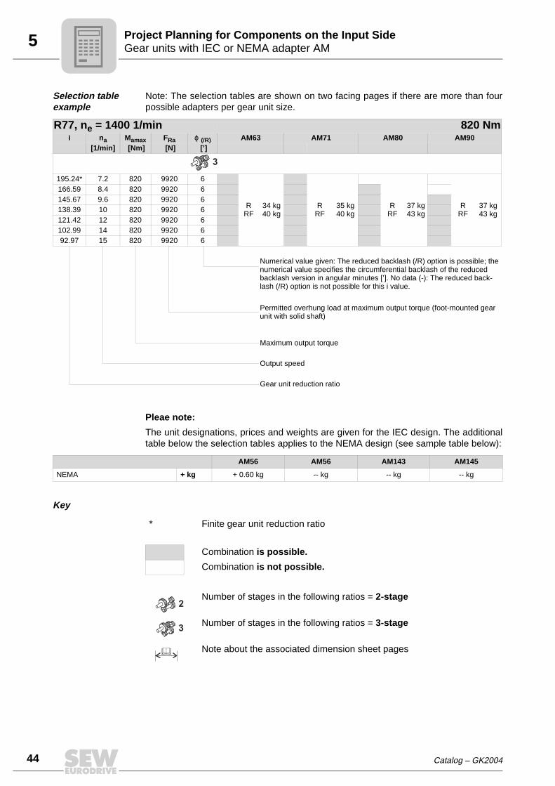
Selection table example
Note: The selection tables are shown on two facing pages if there are more than fourpossible adapters per gear unit size.
Pleae note:
The unit designations, prices and weights are given for the IEC design. The additionaltable below the selection tables applies to the NEMA design (see sample table below):
Key
R77, ne = 1400 1/min 820 Nmi na Mamax FRa ϕ (/R) AM63 AM71 AM80 AM90
[1/min] [Nm] [N] [’]
195.24* 7.2 820 9920 6
RRF
34 kg40 kg
RRF
35 kg40 kg
RRF
37 kg43 kg
RRF
37 kg43 kg
166.59 8.4 820 9920 6145.67 9.6 820 9920 6138.39 10 820 9920 6121.42 12 820 9920 6102.99 14 820 9920 692.97 15 820 9920 6
Numerical value given: The reduced backlash (/R) option is possible; the numerical value specifies the circumferential backlash of the reduced backlash version in angular minutes [’]. No data (-): The reduced back-lash (/R) option is not possible for this i value.
Permitted overhung load at maximum output torque (foot-mounted gear unit with solid shaft)
Maximum output torque
Output speed
Gear unit reduction ratio
3
AM56 AM56 AM143 AM145
NEMA + kg + 0.60 kg -- kg -- kg -- kg
* Finite gear unit reduction ratio
Combination is possible.
Combination is not possible.
Number of stages in the following ratios = 2-stage
Number of stages in the following ratios = 3-stage
Note about the associated dimension sheet pages
2
3

Catalog – GK2004 45
5Gear units with IEC or NEMA adapter AMProject Planning for Components on the Input Side
5
Backstop AM../RS
If the application requires only one direction of rotation, the AM adapter can be config-ured with a backstop. Backstops with centrifugal lift-off sprags are used. The advantageof this design is that the sprags move around inside the backstop without making contactabove a certain speed (lift-off speed). As a result, the backstops operate with no wearor power loss. They are maintenance-free and can be used at high speeds.
Dimensions:
The backstop is completely integrated in the adapter. This means there is no differencein dimensions between an adapter with or without a backstop (see dimension sheets inthe AM adapter section).
Locking torques:
Specify output direction of rotation when ordering
When you order a gear unit with adapter and backstop, it is necessary to indicate thedirection of rotation for the output shaft/output side. The direction of rotation is givenlooking onto the output shaft/output side of the gear unit. For drives with shaft ends atsides A and B, the direction of rotation must be specified as looking onto side A.
To avoid damage, the direction of rotation of the drive must be checked before startingup the machine.
CCW = Rotating counterclockwise
CW = Rotating clockwise
Type Maximum locking torque of backstop Lift-off speed
[Nm] [1/min]
AM80, AM90, AM143, AM145 90 640
AM100, AM112, AM182, AM184 340 600
AM132, AM213/215 700 550
AM160, AM180, AM254/256, AM284/286 1200 630
AM 200, AM225, AM324/326 AM364/365 1450 430
50290AXXFigure 9: Direction of rotation of output
A
B
CCW
CWCCW
CW

46 Catalog – GK2004
5 AQ adapter for servomotorsProject Planning for Components on the Input Side
5.2 AQ adapter for servomotors
An adapter with square flange is used for mounting servomotors onto SEW helical,parallel shaft helical, helical-bevel and helical-worm gear units.
The torque is transmitted via a dog clutch. Possible vibrations and shocks occurringduring operation are effectively attenuated and dissipated by an inserted polyurethanering gear.
Configuration variants
The clutch half on the motor side can be configured either with a clamping ring hub (non-positive, for smooth motor shafts) or a keyway (positive) as required.
• AQH = with clamping ring hub
• AQA = with keyway
04595AXXFigure 10: Helical gear unit with AQ adapter
Catalog – GK2004 47
5AQ adapter for servomotorsProject Planning for Components on the Input Side
5
Torques, mass moments of inertia
Required motor data
As the dimensions of servomotors are not standardized, the following motor data mustbe known to select the appropriate adapter:
• Shaft diameter and length
• Flange dimensions (edge length, diameter, centering shoulder and hole circle)
• Maximum torque
Please do not hesitate to contact us if you have any questions about selection andproject planning.
Type dRZ1)
1) The pinion spigot diameter depends on the gear ratio, please contact SEW-EURODRIVE.
Me max2)
2) Maximum permitted input torque
Jadapter3) [kgm2]
3) Mass moment of inertia of the adapter to be driven
AQ..80/..10 7.7
0.77 x 10⁻⁴
12 13
AQ..100/..AQ..115/1AQ..115/2
10 7.7
1.4 x 10-412 13
14 15
16 15
AQ..115/3
10 7.7
3.1 x 10-412 13
14 19
16 30
AQ..140/1AQ..140/2
16 30
5.1 x 10-418 41
22 53
AQ..140/3
16 30
10 x 10-418 41
22 75
AQ..190/1AQ..190/2
22 7515 x 10-4
28 145
AQ..190/322 75
25 x 10-4
28 170

48 Catalog – GK2004
5 AQ adapter for servomotorsProject Planning for Components on the Input Side
Selection of the gear unit
Determine the gear unit type
↓
Determine gear unit size based on• maximum output torque (Ma max)• gear unit reduction ratio (i)
in the AQ selection tables
↓
Check the maximum permitted overhung load value on the output (FRa)
↓
Check the maximum permitted input torque at the gear unit (Me max) (see “Power ratings, mass moments of intertia" on the previous page)
↓
Is the required adapter size available?
↓
Can the required combination be constructed?
Catalog – GK2004 49
5AQ adapter for servomotorsProject Planning for Components on the Input Side
5
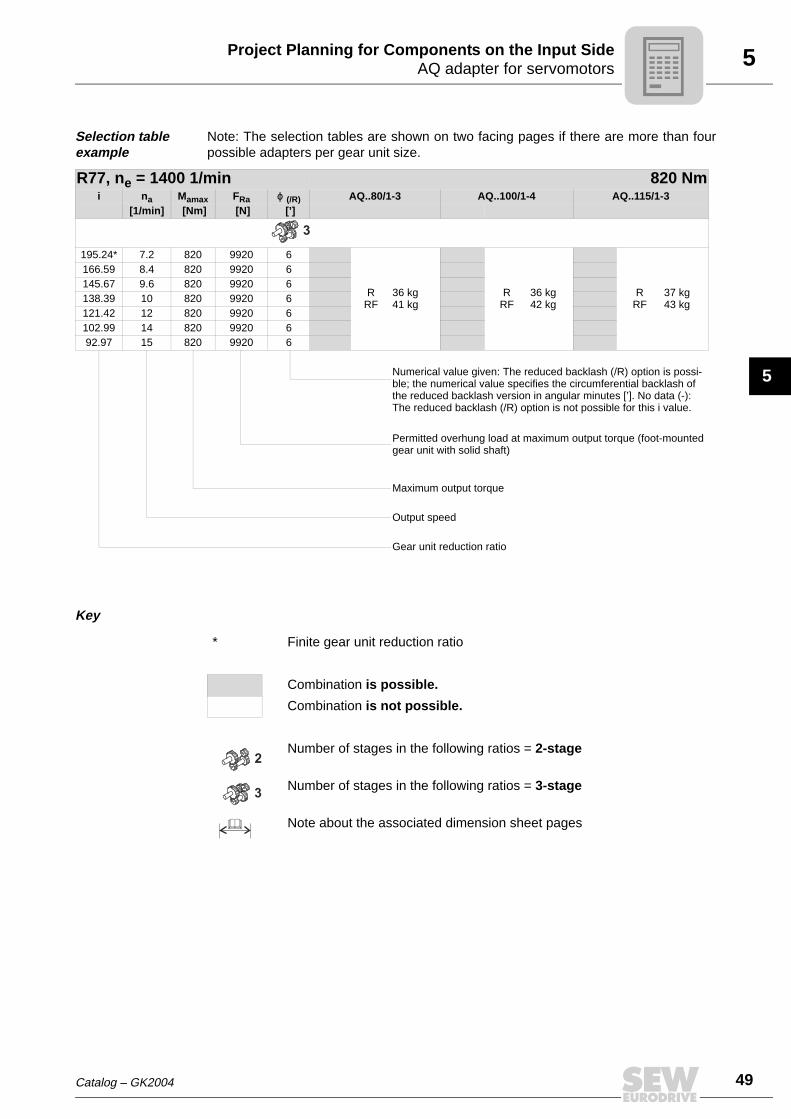
Selection table example
Note: The selection tables are shown on two facing pages if there are more than fourpossible adapters per gear unit size.
Key
R77, ne = 1400 1/min 820 Nmi na Mamax FRa ϕ (/R) AQ..80/1-3 AQ..100/1-4 AQ..115/1-3
[1/min] [Nm] [N] [’]
195.24* 7.2 820 9920 6
RRF
36 kg41 kg
RRF
36 kg42 kg
RRF
37 kg43 kg
166.59 8.4 820 9920 6145.67 9.6 820 9920 6138.39 10 820 9920 6121.42 12 820 9920 6102.99 14 820 9920 692.97 15 820 9920 6
Numerical value given: The reduced backlash (/R) option is possi-ble; the numerical value specifies the circumferential backlash of the reduced backlash version in angular minutes [’]. No data (-): The reduced backlash (/R) option is not possible for this i value.
Permitted overhung load at maximum output torque (foot-mounted gear unit with solid shaft)
Maximum output torque
Output speed
Gear unit reduction ratio
3
* Finite gear unit reduction ratio
Combination is possible.
Combination is not possible.
Number of stages in the following ratios = 2-stage
Number of stages in the following ratios = 3-stage
Note about the associated dimension sheet pages
2
3

50 Catalog – GK2004
5 AR adapter with torque limiting couplingProject Planning for Components on the Input Side
5.3 AR adapter with torque limiting coupling
SEW helical, parallel shaft helical, helical-bevel and helical-worm gear units aredesigned with adapter and torque limiting coupling to protect the machine and the driveagainst overload. IEC standard motors of sizes 71 to 180 can be mounted.
The torque is transmitted through a non-positive engagement involving friction ringpads. The slip torque of the coupling can be set using a setting nut and cup springs.Different slip torques are possible depending on the thickness and arrangement of thecup springs. In the event of an overload, the coupling slips and interrupts the power flowbetween motor and gear unit. This prevents damage to the machine and the drive.
Multi-stage gear units with adapter and torque limit-ing coupling
When used in conjunction with multi-stage gear units, the best place to install theadapter and torque limiting coupling is between the two gear units. Please contact SEW-EURODRIVE if required.
Selection of the gear unit
The unit sizes of the AR adapter with torque limiting coupling are the same as the AMadapter for IEC motors.
As a result, the gear unit can be selected using the selection tables for AM adapters. Inthis case, substitute the unit designation AM with AR and determine the required sliptorque.
Determining the slip torque
The slip torque should be about 1.5 times the rated torque of the drive. When determin-ing the slip torque, bear in mind the maximum permitted output torque of the gear unitas well as the variations in the slip torque of the coupling (+/-20 %) which are a featureof the design.
When you order a gear unit with adapter and torque limiting coupling, you have tospecify the required slip torque of the coupling.
If no information is given in the order, the unit will be set to the maximum permittedoutput torque of the gear unit.
04604AXXFigure 11: Helical-bevel gear unit with AR adapter

Catalog – GK2004 51
5AR adapter with torque limiting couplingProject Planning for Components on the Input Side
5
Torques, slip torques
Speed monitor /W option
We recommend monitoring the speed of the coupling using a speed monitor to avoiduncontrolled slippage of the coupling and the associated wear to the friction ring pads.
The speed of the output end coupling half of the torque limiting coupling is detected in aproximity-type method using a trigger cam and an inductive encoder. The speed monitorcompares the pulses with a defined reference speed. The output relay (NC or NOcontact) trips when the speed drops below the specified speed (overload). The monitoris equipped with a start bypass to suppress error messages during the startup phase.The start bypass can be set within a time window of 0.5 to 15 seconds.
Reference speed, start bypass and switching hysterisis can be set on the speed monitor.
Type Pm1) [kW]
1) Maximum rated power of the mounted standard electric motor at 1400 min-1
MR2) [Nm]
2) Slip torque which can be set based on the cup springs installed
MR2) [Nm] MR
2) [Nm]
AR71 0.37 1 - 6 6.1 - 16 -
AR80 0.75 1 - 6 6.1 - 16 -
AR90 1.5 1 - 6 6.1 - 16 17 - 32
AR100 3.0 5 - 13 14 - 80 -
AR112 4.0 5 - 13 14 - 80 -
AR132S/M 7.5 15 - 130 - -
AR132ML 9.2 15 - 130 - -
AR160 15 30 - 85 86 - 200 -
AR180 22 30 - 85 86 - 300 -
53574AXXFigure 12: : Adapter with torque limiting coupling and speed monitor /W
[1] Trigger cam[2] Encoder (adapter)[3] Driving disc[4] Friction ring pads
[5] Cup spring[6] Slotted nut[7] Friction hub[8] Speed monitor
[1] [2] [3] [4] [5] [6] [7] [8]

52 Catalog – GK2004
5 AR adapter with torque limiting couplingProject Planning for Components on the Input Side
Slip monitor /WS option
In conjunction with VARIBLOC® variable speed gear units (see Variable Speed GearUnits catalog), the speed monitor is replaced by a slip monitor for monitoring the speeddifference between the input and output halves of the coupling.
The signal pick-up depends on the size of the variable speed gear unit and consists oftwo encoders or one encoder and an AC tachogenerator.
Connection The encoder is connected to the monitor using a 2 or 3-core cable (depending on theencoder type).
• Maximum cable length: 500 m with a line cross section of 1.5 mm2
• Standard incoming cable: 3-core / 2 m
• Route the signal lines separately (not in multicore cables) and shield them ifnecessary
• Enclosure: IP40 (terminals IP20)
• Operating voltage: AC 220 V or DC 24 V
• Maximum switching capability of the output relay: 6 A (AC 250 V)
52262AXXFigure 13: Adapter with a torque limiting coupling and slip monitor /WS
[1] Trigger cam[2] Encoder (adapter)[3] Driving disc[4] Friction ring pads[5] Cup spring
[6] Slotted nut[7] Friction hub[8] Slip monitor /WS[9] Encoder IG
22 23 24
A1 A2
19
21 3 4 5 6
7 8 9 10 11 12
13 14 15 16 17 18
20 21
[1] [2] [3] [4] [5] [6] [7] [8] [9]

Catalog – GK2004 53
5AR adapter with torque limiting couplingProject Planning for Components on the Input Side
5
Terminal assignment W
Terminal assignment WS
53653AXXFigure 14: Terminal assignment /W
[1] Relay output[2] Supply voltage AC 230 V (47...63Hz)[3] External slip reset[4] Supply voltage DC 24 V[5] Jumper for synchronous operation monitoring
[6] Signal[7] Encoder [/W] Speed monitor
[4]
[6]
[1]
[2]
1
2
3
4
5
6
7
8
[7]
9
10
11
12
13
14
15
16
/W
52264AXXFigure 15: Terminal assignment /WS
[1] Relay output[2] Supply voltage AC 230 V (47...63Hz)[3] External slip reset[4] Supply voltage DC 24 V[5] Signal
[6] Encoder 1[7] Encoder 2[/WS] Slip monitor
1
2
3
4
5
6
7
8
9
10
11
12
[6]
[4]
[7]
13
14
15
16
17
18
19
20
21
22
23
24
�
�
[5]
[2]
�
�
[5]
L1
LN
�
[1]
[3]/WS

54 Catalog – GK2004
5 AR adapter with torque limiting couplingProject Planning for Components on the Input Side
Dimensions W
Dimensions WS
52250AXXFigure 16: Dimensions /W
53576AXXFigure 17: Dimensions /WS
1 2 3 4 5 6
7 8 9 10 11 12
19 20 21 22 23 24
13 14 15 16 17 18
45 120
78
35.5
Catalog – GK2004 55
5Adapter with a hydraulic centrifugal coupling ATProject Planning for Components on the Input Side
5
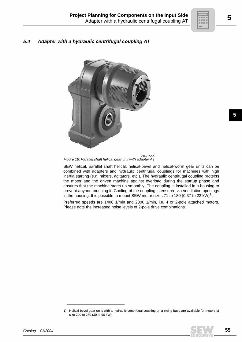
5.4 Adapter with a hydraulic centrifugal coupling AT
SEW helical, parallel shaft helical, helical-bevel and helical-worm gear units can becombined with adapters and hydraulic centrifugal couplings for machines with highinertia starting (e.g. mixers, agitators, etc.). The hydraulic centrifugal coupling protectsthe motor and the driven machine against overload during the startup phase andensures that the machine starts up smoothly. The coupling is installed in a housing toprevent anyone touching it. Cooling of the coupling is ensured via ventilation openingsin the housing. It is possible to mount SEW motor sizes 71 to 180 (0.37 to 22 kW)1).
Preferred speeds are 1400 1/min and 2800 1/min, i.e. 4 or 2-pole attached motors.Please note the increased noise levels of 2-pole drive combinations.
04607AXXFigure 18: Parallel shaft helical gear unit with adapter AT
1) Helical-bevel gear units with a hydraulic centrifugal coupling on a swing base are available for motors ofsize 200 to 280 (30 to 90 kW).

56 Catalog – GK2004
5 Adapter with a hydraulic centrifugal coupling ATProject Planning for Components on the Input Side
Centrifugal coupling
The centrifugal coupling used is a hydrodynamic coupling that operates according to theFöttinger principle. The coupling is filled with oil and consists of a pump wheel (motorside) and a turbine wheel (gear unit side). The pump wheel converts the inputmechanical energy into fluid energy and the turbine wheel converts this energy back intomechanical energy.
The power which the coupling can transmit significantly depends on the speed. As aresult, it is necessary to distinguish between the starting phase and stationary operation.The motor starts up without load during the starting phase until the coupling transmitstorque. The machine is accelerated slowly and smoothly during this phase. Once thestationary operating condition has been reached, a level of operating slip is establishedbetween the motor and the gear unit which is determined by the functional principle ofthe coupling. The motor now only has to supply the load torque demand of the machine,while the coupling helps to absorb any load peaks.
The hydraulic centrifugal coupling is equipped with fusible safety plugs that allow theoperating fluid to be evacuated in the event of excessive temperature (severe overload,blockage). This protects the coupling and the machine from damage.
52251AXXFigure 19: Centrifugal coupling
[1] Filling plug[2] Turbine wheel[3] Coupling half[4] Operating fluid (hydraulic oil)[5] Pump wheel
[6] Flexible connecting coupling[7] Fusible safety plug[A] Gear unit side[B] Motor side
[1]
A B
[2]
[7]
[3] [4] [5] [6]

Catalog – GK2004 57
5Adapter with a hydraulic centrifugal coupling ATProject Planning for Components on the Input Side
5
Characteristic curves
Selection of the gear unit
Sample selection table adapter AT
ne = 1400 1/min:
Motor acceleration Acceleration of driven machine Torque / time characteristic
Motor speed Machine speed Time
M
M
M
M
M
MM/M M/MM/M
K
K
L
K
M
MN
NN
20 sec.
1 1 1
0 0 0
2 2 2
5 sec.
MN Motor torqueML Load torque
MK Coupling torqueMN Fusible safety plug
Determine the gear unit type
↓
Determine gear unit size based on• maximum output torque (Ma max)• gear unit reduction ratio (i)
in the gear unit selection tables with adapter AM
↓
Determine adapter type based on• Motor speed (nM)• Gear unit size• Rated power of the driving motor (Pm)
in the selection tables for adapter AT
Pm Sn
[kW] [%]
[1] [2] [3] [4] [5] [6] [7] [8]
[1] Gear unit size[2] Motor type[3] Motor power[4] Adapter type
[5] Coupling type[6] Fill quantity [l][7] Rated slip of the coupling[8] Dimension sheet page number
l

58 Catalog – GK2004
5 Adapter with a hydraulic centrifugal coupling ATProject Planning for Components on the Input Side
Backstop AT../RS option
If the application requires only one permitted direction of rotation, the hydraulic centrif-ugal coupling can be configured with a backstop. Backstops with centrifugal lift-offsprags are used. The advantage of this design is that the sprags move around in thebackstop without making contact above a certain speed. As a result, the backstopsoperate with no wear or power loss. They are maintenance-free and can be used at highspeeds.
Dimensions The dimensions of the hydraulic centrifugal coupling with backstop AT../RS are identicalto those of the hydraulic centrifugal coupling AT.. (see the dimensions sheets in thehydraulic centrifugal coupling AT.. section).
Locking torques
Specify output direction of rotation when ordering
When you order a gear unit with adapter and backstop, it is necessary to indicate thedirection of rotation for the output shaft/output side. The direction of rotation is givenlooking onto the output shaft/output side of the gear unit. For drives with shaft ends atsides A and B, the direction of rotation must be specified as looking onto side A.
To avoid damage, the direction of rotation of the drive must be checked before startingup the machine.
TypeMaximum locking torque of backstop
[Nm]Lift-off speed
[1/min]
AT311/RS - AT322/RS 340 600
AT421/RS - AT422/RS 700 550
AT522/RS - AT542/RS 1200 630
53721AXXFigure 20: Specify output direction of rotation when ordering
CCW = Rotating counterclockwise
CW = Rotating clockwise
A
B
CCW
CWCCW
CW
Catalog – GK2004 59
5Adapter with a hydraulic centrifugal coupling ATProject Planning for Components on the Input Side
5
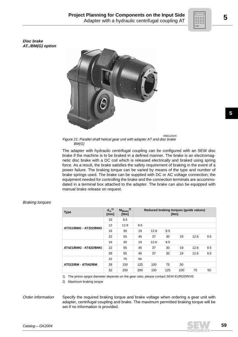
Disc brake AT../BM(G) option
The adapter with hydraulic centrifugal coupling can be configured with an SEW discbrake if the machine is to be braked in a defined manner. The brake is an electromag-netic disc brake with a DC coil which is released electrically and braked using springforce. As a result, the brake satisfies the safety requirement of braking in the event of apower failure. The braking torque can be varied by means of the type and number ofbrake springs used. The brake can be supplied with DC or AC voltage connection; theequipment needed for controlling the brake and the connection terminals are accommo-dated in a terminal box attached to the adapter. The brake can also be equipped withmanual brake release on request.
Braking torques
Order information Specify the required braking torque and brake voltage when ordering a gear unit withadapter, centrifugal coupling and brake. The maximum permitted braking torque will beset if no information is provided.
04611AXXFigure 21: Parallel shaft helical gear unit with adapter AT and disc brake
BM(G)
Typedrz
1)
[mm]
1) The pinion spigot diameter depends on the gear ratio; please contact SEW-EURODRIVE
MBmax2)
[Nm]
2) Maximum braking torque
Reduced braking torques (guide values)[Nm]
AT311/BMG - AT322/BMG
10 9.5
12 12.6 9.5
16 30 19 12.6 9.5
22 55 45 37 30 19 12.6 9.5
AT421/BMG - AT422/BMG
16 30 19 12.6 9.5
22 55 45 37 30 19 12.6 9.5
28 55 45 37 30 19 12.6 9.5
AT522/BM - AT542/BM
22 75 50
28 150 125 100 75 50
32 250 200 150 125 100 75 50

60 Catalog – GK2004
5 AD Input shaft assemblyProject Planning for Components on the Input Side
5.5 AD Input shaft assembly
SEW helical, parallel shaft helical, helical-bevel and helical-worm gear units areequipped with an input shaft assembly for drive via an exposed shaft extension. Theinput shafts have metric dimensions in accordance with the IEC standard (inch dimen-sions on request). The end of the input shaft has a center bore to DIN 332 for mountingand attaching drive components.
The bearings of the input shaft are grease-lubricated. NBR oil seals and gap seals areused for sealing the cover. The rugged bearings of the input shaft permit high overhungloads.
04583AXXFigure 22: Helical gear unit with AD input shaft assembly
Catalog – GK2004 61
5AD Input shaft assemblyProject Planning for Components on the Input Side
5
Selection of the gear unit
Selection table example
Determine the gear unit type
↓
Determine gear unit size based on• maximum output torque (Ma max)• gear unit reduction ratio (i)
in the gear unit selection tables with input shaft assembly ADWhen selecting AD/P, please observe the selection note on page 63 !
↓
Check the maximum permitted overhung load value on the output (FRa).
↓
Check the maximum permitted input power at the gear unit (Pe) by taking account ofthe thermal limit rating (see page 64).
↓
Check the overhung load at the input (FRe).
↓
Please contact SEW if the requirements are more demanding (e.g. higher overhung load on input end).
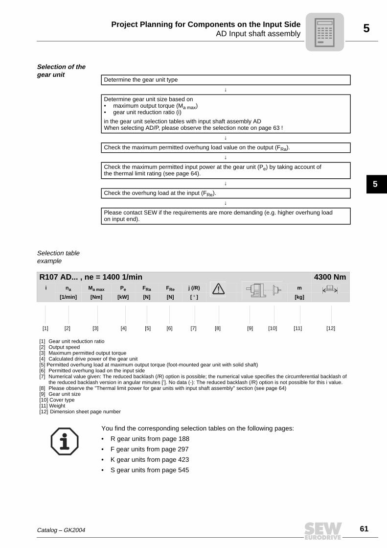
R107 AD... , ne = 1400 1/min 4300 Nmi na Ma max Pe FRa FRe j (/R) m
[1/min] [Nm] [kW] [N] [N] [ ‘ ] [kg]
[1] [2] [3] [4] [5] [6] [7] [8] [9] [10] [11] [12]
[1] Gear unit reduction ratio[2] Output speed[3] Maximum permitted output torque[4] Calculated drive power of the gear unit[5] Permitted overhung load at maximum output torque (foot-mounted gear unit with solid shaft)[6] Permitted overhung load on the input side[7] Numerical value given: The reduced backlash (/R) option is possible; the numerical value specifies the circumferential backlash of
the reduced backlash version in angular minutes [’]. No data (-): The reduced backlash (/R) option is not possible for this i value.[8] Please observe the "Thermal limit power for gear units with input shaft assembly" section (see page 64)[9] Gear unit size[10] Cover type[11] Weight[12] Dimension sheet page number
You find the corresponding selection tables on the following pages:
• R gear units from page 188
• F gear units from page 297
• K gear units from page 423
• S gear units from page 545
62 Catalog – GK2004
5 AD Input shaft assemblyProject Planning for Components on the Input Side
Centering shoulder AD../ZR
The input shaft assembly can be configured with a centering shoulder as an option. Inthis way, a customer's application can be attached to the cover centrally in relation tothe input shaft side.
Backstop AD../RS The input shaft assembly can be supplied with a backstop if the application only requiresone permitted direction of rotation. Backstops with centrifugal lift-off sprags are used.The advantage of this design is that the sprags move around inside the backstop withoutmaking contact above a certain speed (lift-off speed). As a result, the backstops operatewith no wear or power loss. They are maintenance-free and can be used at high speeds.
Dimensions:
The backstop is completely integrated in the cover. This means there is no difference indimensions between an input shaft assembly with or without backstop (see dimensionsheets in the "Input shaft assembly AD" section).
Locking torques:
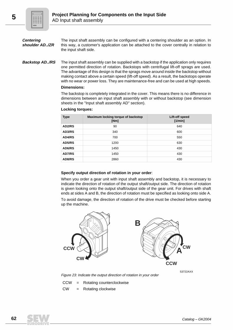
Specify output direction of rotation in your order:
When you order a gear unit with input shaft assembly and backstop, it is necessary toindicate the direction of rotation of the output shaft/output side. The direction of rotationis given looking onto the output shaft/output side of the gear unit. For drives with shaftends at sides A and B, the direction of rotation must be specified as looking onto side A.
To avoid damage, the direction of rotation of the drive must be checked before startingup the machine.
Type Maximum locking torque of backstop[Nm]
Lift-off speed[1/min]
AD2/RS 90 640
AD3/RS 340 600
AD4/RS 700 550
AD5/RS 1200 630
AD6/RS 1450 430
AD7/RS 1450 430
AD8/RS 2860 430
53722AXXFigure 23: Indicate the output direction of rotation in your order
CCW = Rotating counterclockwise
CW = Rotating clockwise
A
B
CCW
CWCCW
CW

Catalog – GK2004 63
5AD Input shaft assemblyProject Planning for Components on the Input Side
5
Motor mounting platform AD.. /P
Belt drives can be set up in a compact configuration using an adjustable motor mountingplatform. The motor mounting platform is arranged in parallel to the input shaft and hastapped holes for IEC standard motors (versions without holes are available on request).The distance from the input shaft can be adjusted using threaded columns.
Selection note (available combi-nations)
See the following table for motors available for the various motor mounting platforms.
If the selected input shaft assembly (with motor mounting platform) cannot be combinedwith the reqired motor, please contact SEW-EURODRIVE.
53585AXXFigure 24: Helical gear unit with input shaft assembly and motor mounting platform
AD../P
Motor mounting platform
Motor type AD2/P AD3/P AD4/P AD5/P AD6/P AD7/P
DT71 5.5
DT80 5.5
DT90 5.5 11
DT100 11
DV112 11
DV132 23
DV160 41
DV180 41
DV200 62
DV225 62
DV250 103
DV280 103
Combination is available / additional weight in kg
The available gear unit/motor combinations for input shaft assemblies with motormounting platforms can be found in the corresponding dimension sheets LN.
• R gear units from page 250
• F gear units from page 372
• K gear units from page 497
• S gear units from page 596
64 Catalog – GK2004
5 AD Input shaft assemblyProject Planning for Components on the Input Side
Thermal limit power for gear units with input shaft assembly
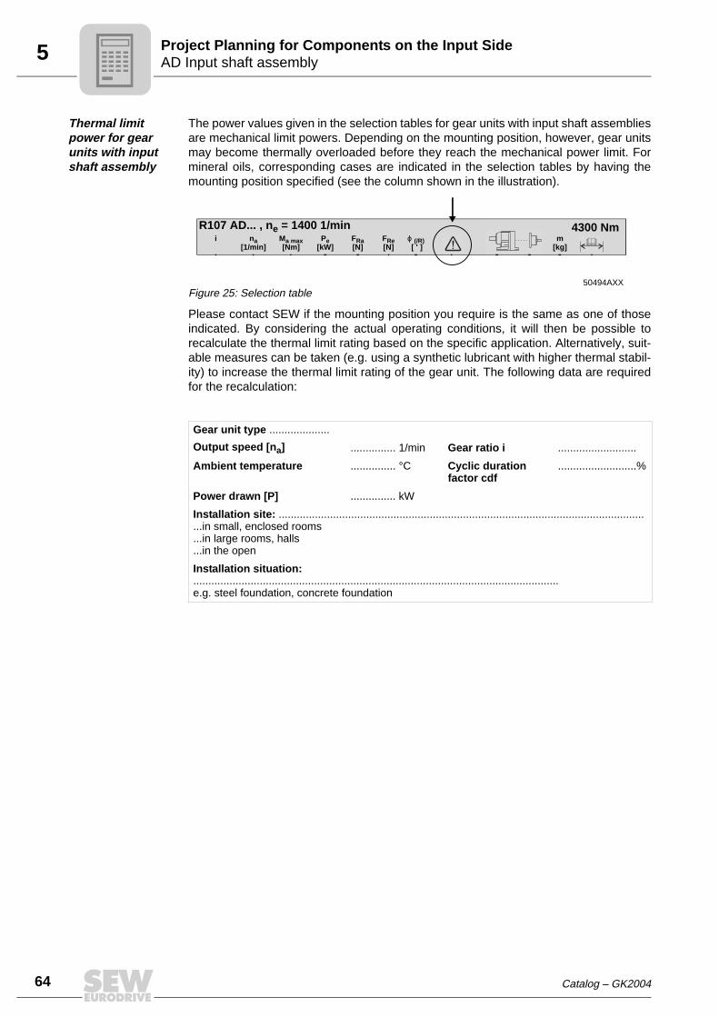
The power values given in the selection tables for gear units with input shaft assembliesare mechanical limit powers. Depending on the mounting position, however, gear unitsmay become thermally overloaded before they reach the mechanical power limit. Formineral oils, corresponding cases are indicated in the selection tables by having themounting position specified (see the column shown in the illustration).
Please contact SEW if the mounting position you require is the same as one of thoseindicated. By considering the actual operating conditions, it will then be possible torecalculate the thermal limit rating based on the specific application. Alternatively, suit-able measures can be taken (e.g. using a synthetic lubricant with higher thermal stabil-ity) to increase the thermal limit rating of the gear unit. The following data are requiredfor the recalculation:
50494AXXFigure 25: Selection table
Gear unit type ....................
Output speed [na] ............... 1/min Gear ratio i ..........................
Ambient temperature ............... °C Cyclic duration factor cdf
..........................%
Power drawn [P] ............... kW
Installation site: ............................................................................................................................in small, enclosed rooms...in large rooms, halls...in the open
Installation situation: .........................................................................................................................e.g. steel foundation, concrete foundation
R107 AD... , ne = 1400 1/min 4300 Nmi na
[1/min]Ma max[Nm]
Pe[kW]
FRa[N]
FRe[N]
ϕ (/R) [ ' ]
m[kg]