5. IP Addresses and Static · PDF file · 2001-09-20IP Addresses and Static...
28
Copyright 1997 by R. Tront Page 5-1 5. IP Addresses and Static Routing This section will show that Internet addresses are assigned and administered in a hierarchical manner. This allows routing to be done efficiently and using only compact routing tables in each node. We will examine how this works, and in particular the concept of the address of a network rather than of a specific destination host. We will then examine how the Internet is running out of certain classes of addresses, and how subnetting is helping to slow the exhaustion of available addresses for new host computers. Readings: Chapters 8 and 10 of [Comer00] Copyright 1997 by R. Tront Page 5-2 Section Table Of Contents 5. IP ADDRESSES AND STATIC ROUTING.................................................................................................................... 1 5.1 BASIC HIERARCHICAL ADDRESSING AND ROUTING....................................................................................................... 3 5.2 HOST VS.NETWORK ADDRESSES.................................................................................................................................. 4 5.3 CLASSES OF IP ADDRESSES........................................................................................................................................... 7 5.3.1 Private (Non-Routable Test) Addresses ............................................................................................................. 10 5.4 STATIC ROUTING......................................................................................................................................................... 11 5.4.1 Routing Tables ................................................................................................................................................... 12 5.4.2 Routing Table Flags........................................................................................................................................... 15 5.4.3 Table Initialization Via Interface Configuration ............................................................................................... 17 5.4.4 Table Initialization Via ‘route add’ ................................................................................................................... 19 5.4.5 Routing Algorithm.............................................................................................................................................. 21 5.5 SUBNETS AND SUBNET MASKS ................................................................................................................................... 23 5.5.1 Motivation for Subnets ....................................................................................................................................... 23 5.5.2 Subnet Portion of an IP Address ........................................................................................................................ 25 5.5.3 An Example Subnetted Network ......................................................................................................................... 27 5.5.4 Subnet Routing Algorithm.................................................................................................................................. 30 5.5.5 Configuring Subnetting ...................................................................................................................................... 33 5.5.6 Non-Byte Subnet Boundaries ............................................................................................................................. 34 5.5.7 Subnetting Summary .......................................................................................................................................... 36 5.6 SPECIAL ADDRESSES................................................................................................................................................... 38 5.7 BROADCAST IP ........................................................................................................................................................... 40 5.7.1 Implementation of IP Broadcasting ................................................................................................................... 42 5.7.2 Security Issues of IP Broadcasting .................................................................................................................... 44 5.8 PROXY ARP................................................................................................................................................................ 45 5.8.1 Using Proxy ARP to Connect Physical Networks .............................................................................................. 45 5.8.2 Security Issues of Proxy ARP ............................................................................................................................. 47 5.8.3 Using Proxy ARP For Serial Links .................................................................................................................... 48 5.9 SUPERNETTING............................................................................................................................................................ 51 5.9.1 Motivation for Supernetting ............................................................................................................................... 51 5.9.2 Grouping Network Addresses into Supernets..................................................................................................... 52 5.9.3 CIDR and Internet Service Providers ................................................................................................................ 53 5.10 REFERENCES ............................................................................................................................... ................................ 55
Transcript of 5. IP Addresses and Static · PDF file · 2001-09-20IP Addresses and Static...
Copyright 1997 by R. Tront Page 5-1
5. IP Addresses and Static RoutingThis section will show that Internet addresses are assignedand administered in a hierarchical manner. This allowsrouting to be done efficiently and using only compactrouting tables in each node. We will examine how thisworks, and in particular the concept of the address of anetwork rather than of a specific destination host. We willthen examine how the Internet is running out of certainclasses of addresses, and how subnetting is helping to slowthe exhaustion of available addresses for new hostcomputers.
Readings: Chapters 8 and 10 of [Comer00]
Copyright 1997 by R. Tront Page 5-2
Section Table Of Contents5. IP ADDRESSES AND STATIC ROUTING....................................................................................................................1
5.1 BASIC HIERARCHICAL ADDRESSING ANDROUTING.......................................................................................................35.2 HOST VS. NETWORKADDRESSES..................................................................................................................................45.3 CLASSES OFIP ADDRESSES...........................................................................................................................................7
5.3.1 Private (Non-Routable Test) Addresses .............................................................................................................105.4 STATIC ROUTING.........................................................................................................................................................11
5.4.1 Routing Tables ...................................................................................................................................................125.4.2 Routing Table Flags...........................................................................................................................................155.4.3 Table Initialization Via Interface Configuration ...............................................................................................175.4.4 Table Initialization Via ‘route add’ ...................................................................................................................195.4.5 Routing Algorithm..............................................................................................................................................21
5.5 SUBNETS ANDSUBNET MASKS...................................................................................................................................235.5.1 Motivation for Subnets .......................................................................................................................................235.5.2 Subnet Portion of an IP Address........................................................................................................................255.5.3 An Example Subnetted Network .........................................................................................................................275.5.4 Subnet Routing Algorithm..................................................................................................................................305.5.5 Configuring Subnetting......................................................................................................................................335.5.6 Non-Byte Subnet Boundaries .............................................................................................................................345.5.7 Subnetting Summary ..........................................................................................................................................36
5.6 SPECIAL ADDRESSES...................................................................................................................................................385.7 BROADCASTIP ...........................................................................................................................................................40
5.7.1 Implementation of IP Broadcasting ...................................................................................................................425.7.2 Security Issues of IP Broadcasting ....................................................................................................................44
5.8 PROXY ARP................................................................................................................................................................455.8.1 Using Proxy ARP to Connect Physical Networks ..............................................................................................455.8.2 Security Issues of Proxy ARP.............................................................................................................................475.8.3 Using Proxy ARP For Serial Links ....................................................................................................................48
5.9 SUPERNETTING............................................................................................................................................................515.9.1 Motivation for Supernetting ...............................................................................................................................515.9.2 Grouping Network Addresses into Supernets.....................................................................................................525.9.3 CIDR and Internet Service Providers ................................................................................................................53
5.10 REFERENCES...............................................................................................................................................................55

Copyright 1997 by R. Tront Page 5-3
5.1 Basic Hierarchical Addressing and Routing
One of the reasons that network administration is difficultis that address have to be assigned by the networkadministrator in a hierarchical manner. Because of this,EACH node in the internet does NOT have to have a hugerouting table in it containing the address and direction toEVERY other host on an internet. Each node’s routingtable need only contain entries for whole networks, andwhich direction it is to get to ANY host on a whole network.Therefore, the routing information for a network containingpossibly thousands of host CPUs occupies only one line inthe routing table of other nodes in the internet.
In addition, networks themselves can be organizedhierarchically such that even within a particular company’snetwork, routing tables are short.
Copyright 1997 by R. Tront Page 5-4
5.2 Host vs. Network Addresses
IP Version 4 addresses are 32 bit binary numbers. It isconvention to display them for human readers as 4 separatebytes, in base 10, separated by periods. This is called‘dotted decimal notation’. E.g.
132.15.140.187
For class B addresses (address classes will be discussed inthe next section), the first two bytes are the designator forthe particular network that the destination computer is on.And the last two bytes indicate the specific computer withinthat destination network. i.e.
• 132.15 is the network.
• 140.187 is the ID of the particular CPU within net 132.15!
It is a convention all through the IP community, throughout the IP literature, and within IP software that networkaddresses are written as a full 32 bits, with the host portionall zeroes. E.g.
132.15.0.0 - the address of a specific network.
Routing works using tables. A routing table with the linebeginning:
132.15.0.0 195.6.57.122
means that to get to any of the computers on net 132.15.0.0,packets should be forwarded to the router whose IP addressis 195.6.57.122. This is instead of forwarding them to someother router. I.e. turn left rather than right.
Copyright 1997 by R. Tront Page 5-5
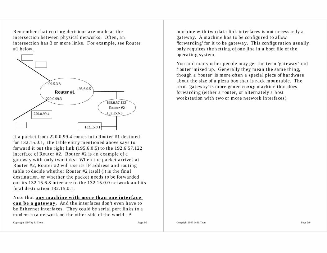
Remember that routing decisions are made at theintersection between physical networks. Often, anintersection has 3 or more links. For example, see Router#1 below.
Router #1
Router #2
195.6.0.5
195.6.57.122
99.5.3.8
220.0.99.3
132.15.6.8
132.15.0.1
220.0.99.4
If a packet from 220.0.99.4 comes into Router #1 destinedfor 132.15.0.1, the table entry mentioned above says toforward it out the right link (195.6.0.5) to the 192.6.57.122interface of Router #2. Router #2 is an example of agateway with only two links. When the packet arrives atRouter #2, Router #2 will use its IP address and routingtable to decide whether Router #2 itself (!) is the finaldestination, or whether the packet needs to be forwardedout its 132.15.6.8 interface to the 132.15.0.0 network and itsfinal destination 132.15.0.1.
Note that any machine with more than one interfacecan be a gateway. And the interfaces don’t even have tobe Ethernet interfaces. They could be serial port links to amodem to a network on the other side of the world. A
Copyright 1997 by R. Tront Page 5-6
machine with two data link interfaces is not necessarily agateway. A machine has to be configured to allow‘forwarding’ for it to be gateway. This configuration usuallyonly requires the setting of one line in a boot file of theoperating system.
You and many other people may get the term ‘gateway’ and‘router’ mixed up. Generally they mean the same thing,though a ‘router’ is more often a special piece of hardwareabout the size of a pizza box that is rack mountable. Theterm ‘gateway’ is more generic: any machine that doesforwarding (either a router, or alternately a hostworkstation with two or more network interfaces).
Copyright 1997 by R. Tront Page 5-7
5.3 Classes of IP Addresses
Recall that to reduce the size of routing tables, some entriesin a routing table specify the route to a whole network ofdestinations. A router has to be able to look at an addressin a routing table and figure out which part of it is thenetwork part, and which part is the destination host CPUpart. This is because there is no column in an IPv4 routingtable to tell the routing algorithm whether a particulardestination address is a network or a host address. There isno reason for this particular design. But given the wayUnix (the original networked operating system) routingtables were formatted, this criterion must be true. If itwasn’t true it wouldn’t be clear which of two almost similar(except for the least significant few bits) destination entriesin a table specify the route for a particular packet.
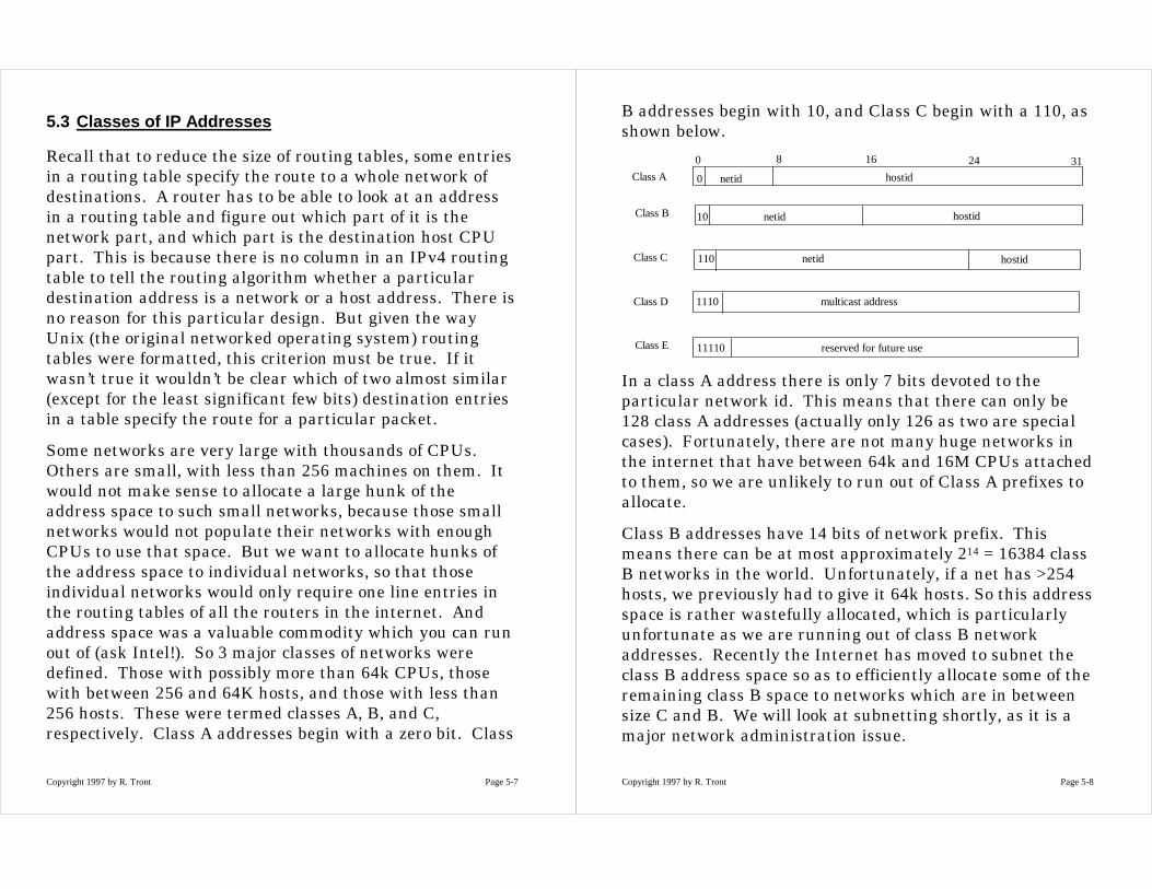
Some networks are very large with thousands of CPUs.Others are small, with less than 256 machines on them. Itwould not make sense to allocate a large hunk of theaddress space to such small networks, because those smallnetworks would not populate their networks with enoughCPUs to use that space. But we want to allocate hunks ofthe address space to individual networks, so that thoseindividual networks would only require one line entries inthe routing tables of all the routers in the internet. Andaddress space was a valuable commodity which you can runout of (ask Intel!). So 3 major classes of networks weredefined. Those with possibly more than 64k CPUs, thosewith between 256 and 64K hosts, and those with less than256 hosts. These were termed classes A, B, and C,respectively. Class A addresses begin with a zero bit. Class
Copyright 1997 by R. Tront Page 5-8
B addresses begin with 10, and Class C begin with a 110, asshown below.
Class A
Class B
Class C
Class D
Class E
0 netid
10 netid
110 netid
1110 multicast address
11110 reserved for future use
168 240 31
hostid
hostid
hostid
In a class A address there is only 7 bits devoted to theparticular network id. This means that there can only be128 class A addresses (actually only 126 as two are specialcases). Fortunately, there are not many huge networks inthe internet that have between 64k and 16M CPUs attachedto them, so we are unlikely to run out of Class A prefixes toallocate.
Class B addresses have 14 bits of network prefix. Thismeans there can be at most approximately 214 = 16384 classB networks in the world. Unfortunately, if a net has >254hosts, we previously had to give it 64k hosts. So this addressspace is rather wastefully allocated, which is particularlyunfortunate as we are running out of class B networkaddresses. Recently the Internet has moved to subnet theclass B address space so as to efficiently allocate some of theremaining class B space to networks which are in betweensize C and B. We will look at subnetting shortly, as it is amajor network administration issue.
Copyright 1997 by R. Tront Page 5-9
There can be at most 221 = 2 million class C networks.Unfortunately, we are fast running out of these as there arealmost that many computerized businesses in the world,and they all now want to attach to the internet. Yet oftenthey only have 10 or 20 CPUs, but waste 256 addresses byapplying for a class C address.
Recall that Internet addresses have to be unique in theworld and there is a central authority, currently theInternet Assigned Numbers Authority (IANA), to managethis. See www.iana.org, (though in future see the InternetCorporation for Assigned Names and Numbers(ICANN)(www.icann.org).
Because of the above network address classification scheme,you can tell whether the destination address of an IP packetis destined for a class A, or B, or C network, just by lookingat the first byte of the address.
Class Lowest NetworkAddress
Highest NetworkAddress
A 1.0.0.0 126.0.0.0
B 128.1.0.0 191.255.0.0
C 192.0.1.0 223.255.255.0
D 224.0.0.0 239.255.255.255
E 240.0.0.0 247.255.255.255
Note that there are several special addresses. For instanceaddress 127.0.0.1 is called the ‘loopback’ address. It ismainly used for testing and for Unix interprocesscommunication within one CPU. When a program uses theloopback address, the packet is send down through the TCP
Copyright 1997 by R. Tront Page 5-10
and IP software, and then received by that very machine. Itis never sent out on any network. This allow programs thatcommunicate with others over the network to be writtenuniformly and still have them communicate with anotherprogram on the same CPU.
Also note that the IP address that begins with five 1 bits isnever used, etc.
5.3.1 Private (Non-Routable Test) Addresses
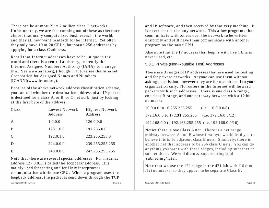
There are 3 ranges of IP addresses that are used for testingand for private networks. Anyone can use them withoutasking permission; however they are for use internal to yourorganization only. No routers in the Internet will forwardpackets with such addresses. There is one class A range,one class B range, and one part way between with a 12 bitnetmask:
10.0.0.0 to 10.255.255.255 (i.e. 10.0.0.0/8)
172.16.0.0 to 172.31.255.255 (i.e. 172.16.0.0/12)
192.168.0.0 to 192.168.255.255 (i.e. 192.168.0.0/16)
Notice there is one Class A net. There is a net rangemidway between A and B whose first byte would lead you tobelieve this is 16 adjacent class B nets. Similarly, there isanother net that appears to be 256 class C nets. You can doanything you want with these ranges, including supernet orsubnet them. We will discuss ‘supernetting’ and‘subnetting’ later.
Note that we use the 172 range in the 471 lab with /16 (not/12) netmasks, so they appear to be separate Class B.

Copyright 1997 by R. Tront Page 5-11
5.4 Static Routing
A machine that uses ‘static’ routing refers to fixed routingtable content that is manually set, either at boot time frominterface or network configuration files, or at run time bythe administrator.
This is in contrast to machines that allow their routingtables to be updated with information obtained over thenetwork via routing protocols such as RIP or OSPF. Suchmachines or networks are termed to be using ‘dynamicrouting’. They run routing daemon programs that adjustthe contents of the routing tables dynamically.
In addition to my example that follows, [Stevens94] pages112-117 also has a good discussion of routing tables, andanother example of a network (on the inside front cover) andeach machine’s routing table.
Copyright 1997 by R. Tront Page 5-12
5.4.1 Routing Tables
Routing tables are a run time table maintained in RAM.They are not kept in a particular file. This is because evenfixed routing tables can be changed at run time by thesystem administrator or as a result of reception of ICMPredirect messages. So to see the current routing table, youmust enter a (Unix) command like:
>netstat -nr
Consider the following simple LAN with only one connectionto the Internet. But the way, let me make a very importantpoint. Notice the CPU named ‘cloud’ is a gateway, and theIP address of your Internet Service Provider (ISP) is78.55.9.254.
sun
172.16.0.1
rain
172.16.0.2
78.55.9.3
cloud
172.16.0.3
The Internet78.55.9.254
Copyright 1997 by R. Tront Page 5-13
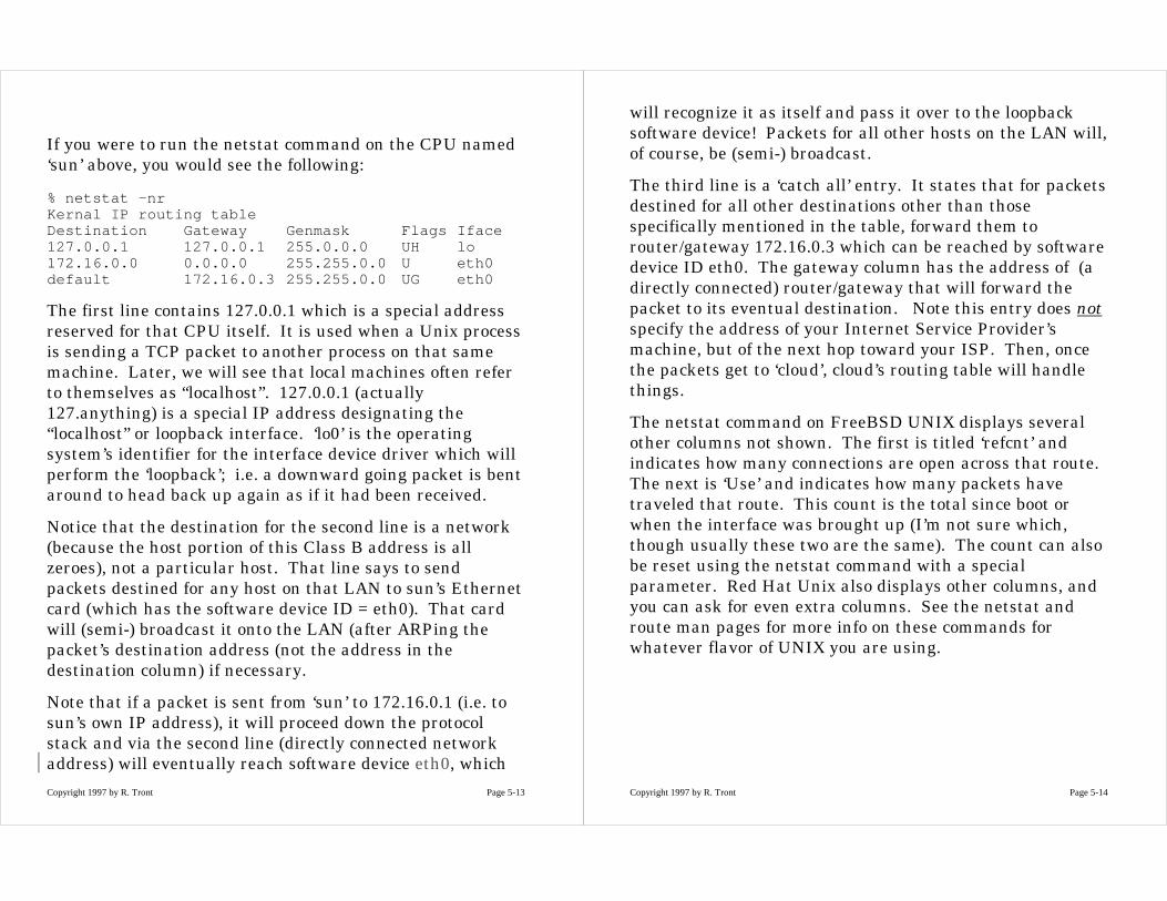
If you were to run the netstat command on the CPU named‘sun’ above, you would see the following:
% netstat -nrKernal IP routing tableDestination Gateway Genmask Flags Iface127.0.0.1 127.0.0.1 255.0.0.0 UH lo172.16.0.0 0.0.0.0 255.255.0.0 U eth0default 172.16.0.3 255.255.0.0 UG eth0
The first line contains 127.0.0.1 which is a special addressreserved for that CPU itself. It is used when a Unix processis sending a TCP packet to another process on that samemachine. Later, we will see that local machines often referto themselves as “localhost”. 127.0.0.1 (actually127.anything) is a special IP address designating the“localhost” or loopback interface. ‘lo0’ is the operatingsystem’s identifier for the interface device driver which willperform the ‘loopback’; i.e. a downward going packet is bentaround to head back up again as if it had been received.
Notice that the destination for the second line is a network(because the host portion of this Class B address is allzeroes), not a particular host. That line says to sendpackets destined for any host on that LAN to sun’s Ethernetcard (which has the software device ID = eth0). That cardwill (semi-) broadcast it onto the LAN (after ARPing thepacket’s destination address (not the address in thedestination column) if necessary.
Note that if a packet is sent from ‘sun’ to 172.16.0.1 (i.e. tosun’s own IP address), it will proceed down the protocolstack and via the second line (directly connected networkaddress) will eventually reach software device eth0, which
Copyright 1997 by R. Tront Page 5-14
will recognize it as itself and pass it over to the loopbacksoftware device! Packets for all other hosts on the LAN will,of course, be (semi-) broadcast.
The third line is a ‘catch all’ entry. It states that for packetsdestined for all other destinations other than thosespecifically mentioned in the table, forward them torouter/gateway 172.16.0.3 which can be reached by softwaredevice ID eth0. The gateway column has the address of (adirectly connected) router/gateway that will forward thepacket to its eventual destination. Note this entry does notspecify the address of your Internet Service Provider’smachine, but of the next hop toward your ISP. Then, oncethe packets get to ‘cloud’, cloud’s routing table will handlethings.
The netstat command on FreeBSD UNIX displays severalother columns not shown. The first is titled ‘refcnt’ andindicates how many connections are open across that route.The next is ‘Use’ and indicates how many packets havetraveled that route. This count is the total since boot orwhen the interface was brought up (I’m not sure which,though usually these two are the same). The count can alsobe reset using the netstat command with a specialparameter. Red Hat Unix also displays other columns, andyou can ask for even extra columns. See the netstat androute man pages for more info on these commands forwhatever flavor of UNIX you are using.
Copyright 1997 by R. Tront Page 5-15
5.4.2 Routing Table Flags
There are several possible flags:
• U means the software device is ‘up’ andenabled/functioning.
• H means the address in the destination column is aspecific CPU (i.e. host) address, so a full 32 bit comparisonis done with the packet’s destination address. Having theH flag is also useful because later you will see that it isnot easy to visually determine from an address in thedestination column whether the least significant bits arezero (indicating a network address) or not.
• The G flag indicates that the address in the gatewaycolumn is NOT on the same network or subnet as theaddress in the destination column. Instead, it is that of anintermediate router/gateway which will take you towardthe destination’s network. Interestingly, if G present andon an Ethernet, you ARP the address in the gatewaycolumn. If G not present, you ARP the packet’sdestination (not the address in the destination column).Thus the G flag determines which Ethernet address iswritten on the Layer 2 envelope!
• The A flag indicates the line was installed by addrconf.
• An M flag means modified by dynamic routing daemon, orthat there was an incorrect line in the initial routingtable, and that that line has been modified as a result ofreceiving an ICMP redirect message. The systemadministrator should make an effort to correct this lattercase by suitable corrections to the boot configuration files.
Copyright 1997 by R. Tront Page 5-16
• A D flag means that that line was added (not changed) bya dynamic routing daemon or as a result of a ICMPredirect packet being received.
• An R flag means a reinstated route for dynamic routing.
• C is a cache entry. Not sure what this is; perhaps arpcache entry???
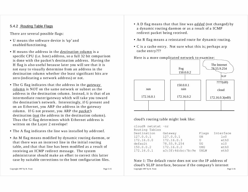
Here is a more complicated network to examine:
sun
172.16.0.1
150.0.0.1rain
172.16.0.2
????(sl0)
cloud
172.16.0.3(ed0)
The Internet78.55.9.254
SLIP
Fog150.0.0.2
cloud’s routing table might look like:
cloud% netstat -nrRouting TablesDestination Gateway Flags Interface127.0.0.1 127.0.0.1 UH lo0172.16.0.0 172.16.0.3 U eth0default 78.55.9.254 UG sl0150.0.0.2 172.16.0.2 UHG eth0172.16.0.1 a3:3f:4d:bc:7b:9e UHLW eth0
Note 1: The default route does not use the IP address ofcloud’s SLIP interface, because if the company’s internet
Copyright 1997 by R. Tront Page 5-17
connection is dial-up, it may be that the ISP will assign thatIP address different for each call. You thus need a G flagand specify the ISP’s IP address as the next hop.
Note 2: If cloud wants to ping 150.0.0.1, you need:
150.0.0.1 172.16.0.2 UHG eth0
Do not use a gateway column of 172.16.0.3 (with or withouta G) as it won’t work. For instance, if not G, you will ARP150.0.0.1 and no one will answer!
5.4.3 Table Initialization Via Interface Configuration
When an interface is initialized (either by a boot script or bya network administrator), a routing table entry isautomatically made. If the interface is for a broadcast link,a network entry is made. If it is for a point to pointinterface (like a serial port to a modem), the slip or PPPinterface will, when a link is ‘brought up’ make a host entry(H flag) for the address at the other end of the link.Because this is to a directly connected node, the gatewaycolumn will be set to the IP address of the outgoing serialinterface.
The command to configure the first Ethernet interface andbring it up is:
ifconfig eth0 inet 172.16.0.1
Normally, you should add a few more parameters to thiscommand, but they are not absolutely necessary on anunsubnetted network that also knows the correct defaultbroadcast suffix (to be discussed later). If the host hasseveral Ethernet cards, the software device ID for thesecond one is eth1.
Copyright 1997 by R. Tront Page 5-18
The command to configure a serial interface which useseither the Serial Line IP (SLIP) protocol, or the Point toPoint Protocol (PPP), contains two IP addresses:
1. The IP address to be assigned to the local end of the link.
2. And the IP address at the other end of the link to whichyou are connecting to.
The commands for this vary from one OS to another, butyou can see that the command will contains enoughinformation to automatically make a routing table entry.The destination column gets the IP address of the node atthe far end of the link, and the gateway column is filled inwith the IP address of the localhost’s serial line softwaredevice (e.g. sl0 or slip0).
The above commands are most often put in the boot files. InFreeBSD 2.2.2, the data for the command is set in an OSenvironment variable from an entry in /etc/rc.conf. Andthen the other boot files use that environment variable inan ifconfig command.
Usually there is something in this file that mentions thelocalhost 127.0.0.1 lo interface as well.
Actually, their are quite a number of files that the bootprocess reads or interprets, but on FreeBSD Unix most ofthem get their configurations instructions from the onecentral /etc/rc.conf file.
Copyright 1997 by R. Tront Page 5-19
5.4.4 Table Initialization Via ‘route add’
So far we have talked about routing table entries that areindirectly and automatic made by the mere act of telling theOS about the interfaces. Often we must add additionalentries to the routing table (e.g. default or routes for multi-connected nets). The OS cannot automatically figure outthe default route from just the data about the interfacesthat are present.
Thus the network administrator also normally enables (inthe boot files) ‘route add’ commands. For instance, theadministrator determines the best default route and addsthis command to the boot files:
route add default gw 78.55.9.254
This specifies that the default route is via gateway78.55.9.254.
If you want to add a special route to a specific host/subnet/net for which the default route will not be correct, then usea ‘route add’ command for each unusual route. E.g.route add -net 172.17 gw 172.16.0.254
If the destination is obviously a network address (i.e. hostportion all 0s), it will understand the destination is anetwork and route packets for all host on that networkthere. If the destination is a host, only packets for that hostwill use that table entry. Be careful though when usingabbreviations like 172.17 in place of 172.17.0.0! If you don’tuse -net, the stupid computer thinks 172.17 means theindividual host 172.0.0.17! It is thus best when adding aroute to a network rather than a host to always use “-net”.
Copyright 1997 by R. Tront Page 5-20
Note that when routing to classless nets, you must use “-net’ and in addition must use in the route command a‘netmask’ parameter that looks for example like “netmask255.248.0.0”.
Some OSs allow you an additional integer parameter to helprouting protocols: the ‘so called’ hop count. It is actually oneminus the hop count. I.e. the number of gateways betweenyou and the destination(s). If the hop count at the end ofthe ‘route add’ command is >0, then the G flag is set in theline created in the routing table.
On the other hand, FreeBSD Unix uses a different methodto set the G flag: if the gateway entry is not one of thatmachine’s interfaces, it sets the G flag. If it is one of thatmachine’s interfaces, you should use ‘-interface’ in front ofeither an interface address or interface name (like sl0).
On yet another hand, on Linux, you need to use the “gw”parameter specifier whenever you are specifying a gateway.E.g.
%route add -net 172.5.0.0 gw 105.3.2.254
%route add -net 172.5.0.0 gw myGate3
If you leave the ‘gw’ off, it will wrongly assume thatmyGate3 is an interface rather than the DNS name of yourrouter.
Copyright 1997 by R. Tront Page 5-21
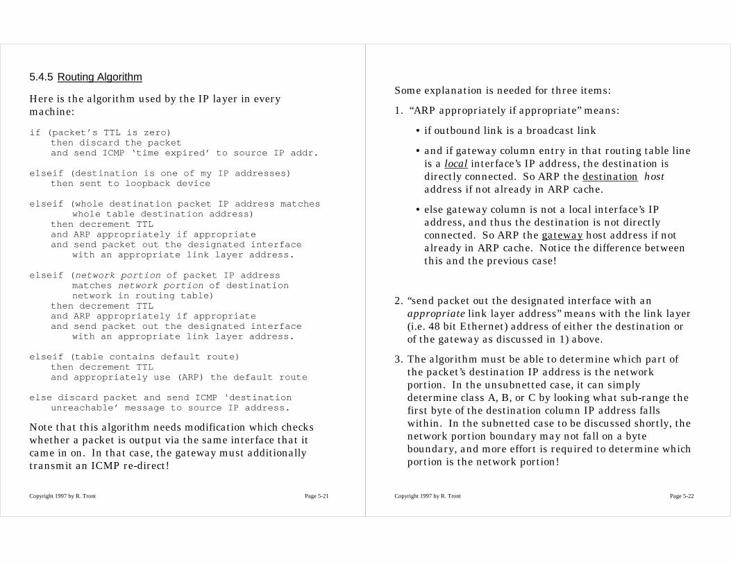
5.4.5 Routing Algorithm
Here is the algorithm used by the IP layer in everymachine:
if (packet’s TTL is zero)then discard the packetand send ICMP ‘time expired’ to source IP addr.
elseif (destination is one of my IP addresses)then sent to loopback device
elseif (whole destination packet IP address matcheswhole table destination address)
then decrement TTLand ARP appropriately if appropriateand send packet out the designated interface
with an appropriate link layer address.
elseif ( network portion of packet IP addressmatches network portion of destinationnetwork in routing table)
then decrement TTLand ARP appropriately if appropriateand send packet out the designated interface
with an appropriate link layer address.
elseif (table contains default route)then decrement TTLand appropriately use (ARP) the default route
else discard packet and send ICMP ‘destinationunreachable’ message to source IP address.
Note that this algorithm needs modification which checkswhether a packet is output via the same interface that itcame in on. In that case, the gateway must additionallytransmit an ICMP re-direct!
Copyright 1997 by R. Tront Page 5-22
Some explanation is needed for three items:
1. “ARP appropriately if appropriate” means:
• if outbound link is a broadcast link
• and if gateway column entry in that routing table lineis a local interface’s IP address, the destination isdirectly connected. So ARP the destination hostaddress if not already in ARP cache.
• else gateway column is not a local interface’s IPaddress, and thus the destination is not directlyconnected. So ARP the gateway host address if notalready in ARP cache. Notice the difference betweenthis and the previous case!
2. “send packet out the designated interface with anappropriate link layer address” means with the link layer(i.e. 48 bit Ethernet) address of either the destination orof the gateway as discussed in 1) above.
3. The algorithm must be able to determine which part ofthe packet’s destination IP address is the networkportion. In the unsubnetted case, it can simplydetermine class A, B, or C by looking what sub-range thefirst byte of the destination column IP address fallswithin. In the subnetted case to be discussed shortly, thenetwork portion boundary may not fall on a byteboundary, and more effort is required to determine whichportion is the network portion!
Copyright 1997 by R. Tront Page 5-23
5.5 Subnets and Subnet Masks
5.5.1 Motivation for Subnets
It has been realized over the last few years that the numberof stations (and networks) attached to the Internet wasgrowing exponentially. This is very serious as it means the32 bit address space of the IP protocol will quickly be usedup. What’s worse the problem was mostly just inefficientuse of that address space, rather than lack of any unusedhost addresses.
This is because networks administrators are granted blocksof address space from the IANA for each physical network.And the blocks really only come in 3 sizes (A, B, and C). Ifyou needed a net with only 3 addresses, you were granted aclass C network address containing over 250 host addresses.You use only 3, and thus there were about 250 addressesreserved for your network that are unused by you, andungrantable to any other network.
Similarly, say your company has never previously beenconnected to the Internet. You have 4 physical networksrouted together. Each physical network has about 200 hostson it. You would hate it if the InterNIC granted you fourclass C network addresses, because you anticipate eachnetwork growing to more than 254 hosts. When thishappened to a particular net, you would have to apply for aclass B address and give each host a new address (which isan administrative nightmare to do without bringing thenetwork down or making a mistake). So you ask for 4 classB network addresses. This gives you 4 x 64K possibly hostaddresses, yet you are only using 800. You are wasting over¼ million host addresses!
Copyright 1997 by R. Tront Page 5-24
Not only that, the original Internet backbone routing wasnot done hierarchically. Thus the routers on the Internetbackbone would needed to store the route to EVERYphysical network on the internet. That means, all 4 Class Baddress routes above would need to be stored in everybackbone router, even though the company only has oneinbound gateway from the Internet!
Copyright 1997 by R. Tront Page 5-25
5.5.2 Subnet Portion of an IP Address
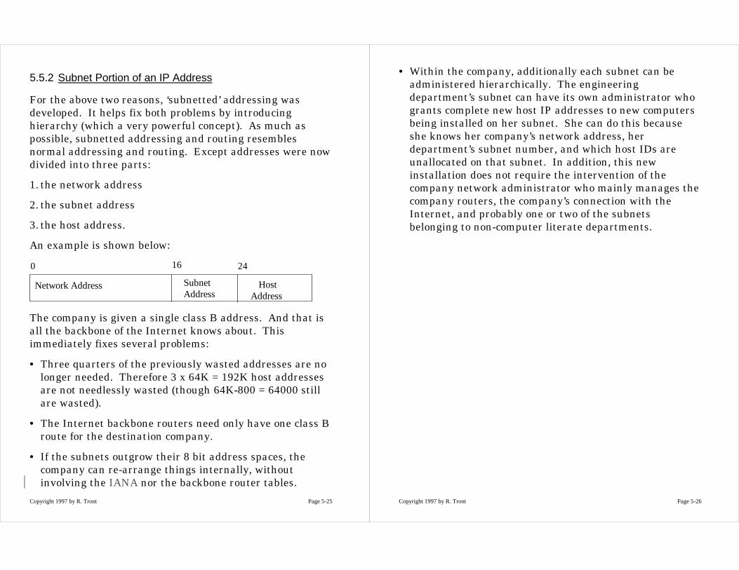
For the above two reasons, ‘subnetted’ addressing wasdeveloped. It helps fix both problems by introducinghierarchy (which a very powerful concept). As much aspossible, subnetted addressing and routing resemblesnormal addressing and routing. Except addresses were nowdivided into three parts:
1. the network address
2. the subnet address
3. the host address.
An example is shown below:
Network Address SubnetAddress
HostAddress
0 16 24
The company is given a single class B address. And that isall the backbone of the Internet knows about. Thisimmediately fixes several problems:
• Three quarters of the previously wasted addresses are nolonger needed. Therefore 3 x 64K = 192K host addressesare not needlessly wasted (though 64K-800 = 64000 stillare wasted).
• The Internet backbone routers need only have one class Broute for the destination company.
• If the subnets outgrow their 8 bit address spaces, thecompany can re-arrange things internally, withoutinvolving the IANA nor the backbone router tables.
Copyright 1997 by R. Tront Page 5-26
• Within the company, additionally each subnet can beadministered hierarchically. The engineeringdepartment’s subnet can have its own administrator whogrants complete new host IP addresses to new computersbeing installed on her subnet. She can do this becauseshe knows her company’s network address, herdepartment’s subnet number, and which host IDs areunallocated on that subnet. In addition, this newinstallation does not require the intervention of thecompany network administrator who mainly manages thecompany routers, the company’s connection with theInternet, and probably one or two of the subnetsbelonging to non-computer literate departments.
Copyright 1997 by R. Tront Page 5-27
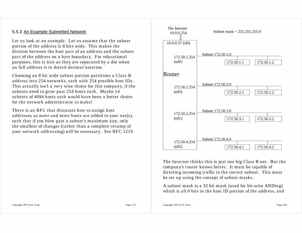
5.5.3 An Example Subnetted Network
Let us look at an example. Let us assume that the subnetportion of the address is 8 bits wide. This makes thedivision between the host part of an address and the subnetpart of the address on a byte boundary. For educationalpurposes, this is nice as they are separated by a dot whenan full address is in dotted decimal notation.
Choosing an 8 bit wide subnet portion partitions a Class Baddress into 254 networks, each with 254 possible host IDs.This actually isn’t a very wise choice for this company, if thesubnets need to grow past 254 hosts each. Maybe 14subnets of 4094 hosts each would have been a better choicefor the network administrator to make!
There is an RFC that discusses how to assign hostaddresses as more and more hosts are added to your net(s),such that if you blow past a subnet’s maximum size, onlythe smallest of changes (rather than a complete revamp ofyour network addressing) will be necessary. See RFC 1219
Copyright 1997 by R. Tront Page 5-28
172.50.3.1 172.50.3.2
Subnet 172.50.3.0172.50.3.254(ed1)
Router
172.50.2.1 172.50.2.2
Subnet 172.50.2.0172.50.2.254(ed5)
172.50.1.1 172.50.1.2
Subnet 172.50.1.0172.50.1.254(ed0)
172.50.4.1 172.50.4.2
Subnet 172.50.4.0172.50.4.254(ed2)
10.0.0.57 (sl0)
The Internet10.0.0.254 Subnet mask = 255.255.255.0
The Internet thinks this is just one big Class B net. But thecompany’s router knows better. It must be capable ofdirecting incoming traffic to the correct subnet. This mustbe set up using the concept of subnet masks.
A subnet mask is a 32 bit mask (used for bit-wise ANDing)which is all 0 bits in the host ID portion of the address, and
Copyright 1997 by R. Tront Page 5-29
all 1s elsewhere. For instance, all the interfaces in thecompany subnets will use the subnet mask:
11111111 11111111 11111111 00000000
which is usually written 255.255.255.0
You will sometimes have to specify the subnet mask byspecifying how wide the subnet portion of the address is(e.g. in the above example it is 8). The Cisco router in rarecommands will sometimes require this.
Also, you will sometimes see a host IP address and maskdisplayed in compact form like this:
172.50.4.2/24
or a network address like this:
172.50.4/24 or 172.50.4.0/24
which means a subnet mask with 24 left justified 1 bits.
Note that in a routing table, when the host portion of anaddress is all zeros (this is not always obvious in dotteddecimal notation), the address represents the address of thewhole subnet. In a packet header, an all zero host portionmeans something different (to be discussed later).
Copyright 1997 by R. Tront Page 5-30
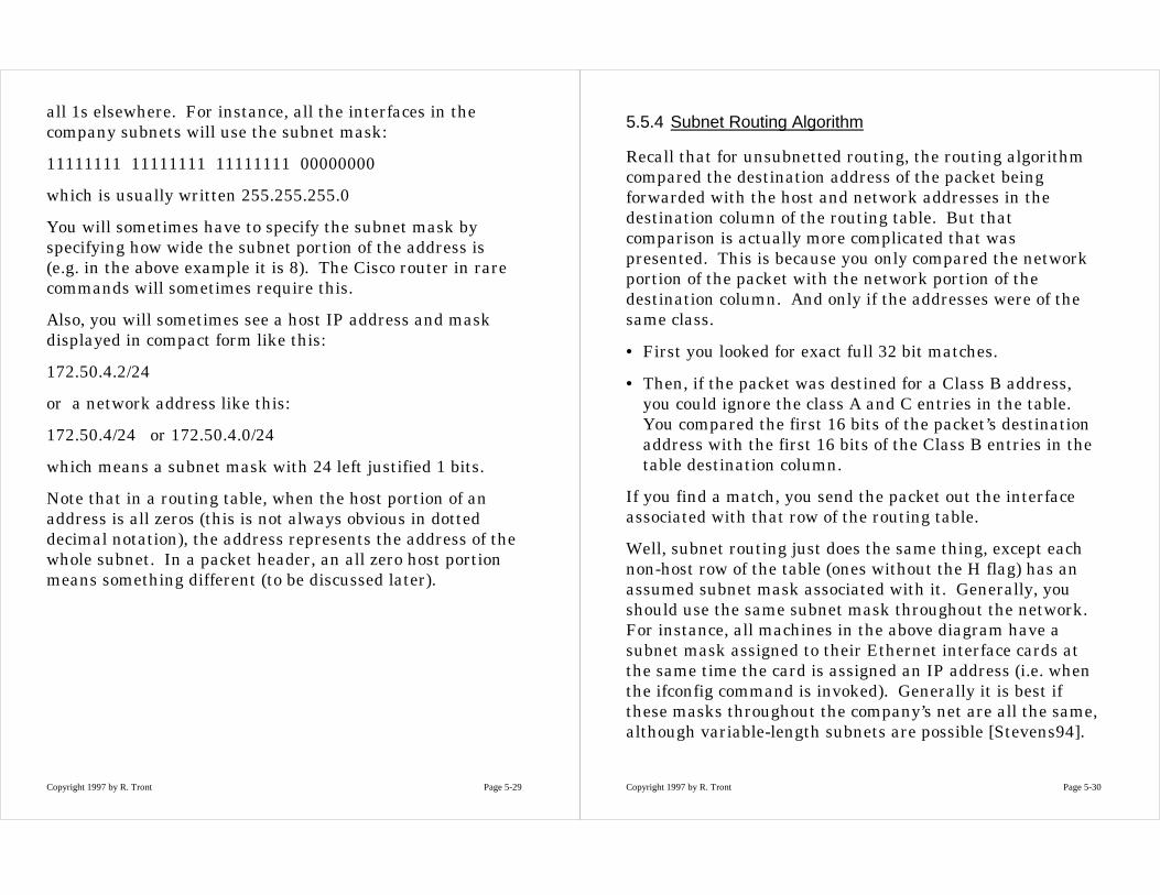
5.5.4 Subnet Routing Algorithm
Recall that for unsubnetted routing, the routing algorithmcompared the destination address of the packet beingforwarded with the host and network addresses in thedestination column of the routing table. But thatcomparison is actually more complicated that waspresented. This is because you only compared the networkportion of the packet with the network portion of thedestination column. And only if the addresses were of thesame class.
• First you looked for exact full 32 bit matches.
• Then, if the packet was destined for a Class B address,you could ignore the class A and C entries in the table.You compared the first 16 bits of the packet’s destinationaddress with the first 16 bits of the Class B entries in thetable destination column.
If you find a match, you send the packet out the interfaceassociated with that row of the routing table.
Well, subnet routing just does the same thing, except eachnon-host row of the table (ones without the H flag) has anassumed subnet mask associated with it. Generally, youshould use the same subnet mask throughout the network.For instance, all machines in the above diagram have asubnet mask assigned to their Ethernet interface cards atthe same time the card is assigned an IP address (i.e. whenthe ifconfig command is invoked). Generally it is best ifthese masks throughout the company’s net are all the same,although variable-length subnets are possible [Stevens94].
Copyright 1997 by R. Tront Page 5-31
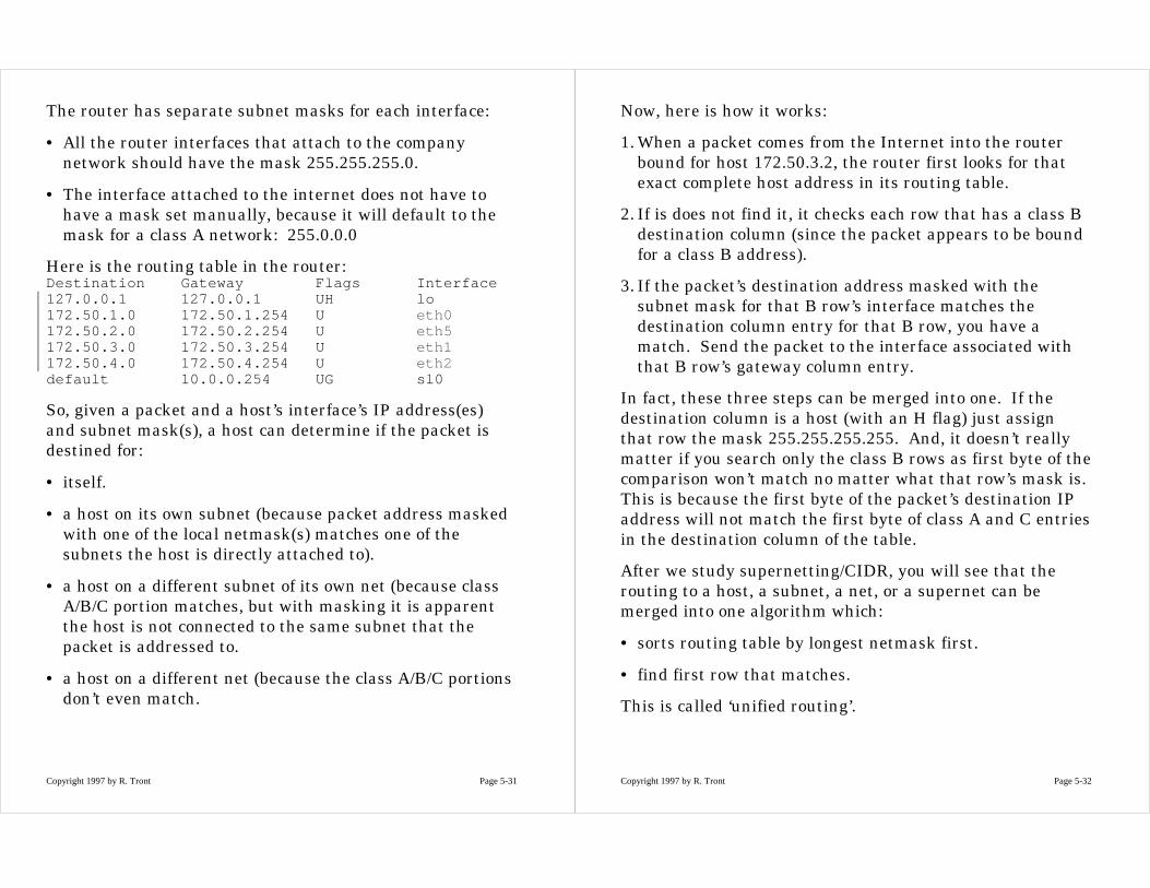
The router has separate subnet masks for each interface:
• All the router interfaces that attach to the companynetwork should have the mask 255.255.255.0.
• The interface attached to the internet does not have tohave a mask set manually, because it will default to themask for a class A network: 255.0.0.0
Here is the routing table in the router:Destination Gateway Flags Interface127.0.0.1 127.0.0.1 UH lo172.50.1.0 172.50.1.254 U eth0172.50.2.0 172.50.2.254 U eth5172.50.3.0 172.50.3.254 U eth1172.50.4.0 172.50.4.254 U eth2default 10.0.0.254 UG sl0
So, given a packet and a host’s interface’s IP address(es)and subnet mask(s), a host can determine if the packet isdestined for:
• itself.
• a host on its own subnet (because packet address maskedwith one of the local netmask(s) matches one of thesubnets the host is directly attached to).
• a host on a different subnet of its own net (because classA/B/C portion matches, but with masking it is apparentthe host is not connected to the same subnet that thepacket is addressed to.
• a host on a different net (because the class A/B/C portionsdon’t even match.
Copyright 1997 by R. Tront Page 5-32
Now, here is how it works:
1. When a packet comes from the Internet into the routerbound for host 172.50.3.2, the router first looks for thatexact complete host address in its routing table.
2. If is does not find it, it checks each row that has a class Bdestination column (since the packet appears to be boundfor a class B address).
3. If the packet’s destination address masked with thesubnet mask for that B row’s interface matches thedestination column entry for that B row, you have amatch. Send the packet to the interface associated withthat B row’s gateway column entry.
In fact, these three steps can be merged into one. If thedestination column is a host (with an H flag) just assignthat row the mask 255.255.255.255. And, it doesn’t reallymatter if you search only the class B rows as first byte of thecomparison won’t match no matter what that row’s mask is.This is because the first byte of the packet’s destination IPaddress will not match the first byte of class A and C entriesin the destination column of the table.
After we study supernetting/CIDR, you will see that therouting to a host, a subnet, a net, or a supernet can bemerged into one algorithm which:
• sorts routing table by longest netmask first.
• find first row that matches.
This is called ‘unified routing’.
Copyright 1997 by R. Tront Page 5-33
5.5.5 Configuring Subnetting
It is unfortunate that on some old OSs the netstat -nrcommand that prints out the routing table does not printout the mask associated with each row (NT and Linux nowdo!). But you can see the mask for each interface by usingthe ifconfig -a command to see the info about everyinterface.
To add an interface that attaches to a subnet, you need touse a variant of the ifconfig command. For an Ethernetinterface named eth0, it would take this form:
ifconfig eth0 inet 172.50.1. 3 netmask 255.255.255.0
This assigns eth0 a class B address, yet puts the subnet/hostportion boundary after the 3rd byte!
Note: If you have to add a special route toward a subnetusing the ‘route add’ command where the destination is notclearly a Class A, B, or C network (e.g. the host portion doesnot appear to be zero) and you do not specify the netmask,on some OSs that added routing table row will be assignedthe netmask associated with the outbound interface. This isso even if that route must make several hops to its eventualdestination (which may in rare circumstances have adifferent mask than the outbound interface)! This is rarebecause in most subnetting, the subnetted destinations areon directly connected subnets (which have the samenetmask as that router’s outbound interface to that subnet),or they are on a corporate set of subnets that all have thesame mask as the subnet this host is on. If this netmask‘inherited’ from the interface is not appropriate, you mustuse the ‘netmask’ feature of the route add command.
Copyright 1997 by R. Tront Page 5-34
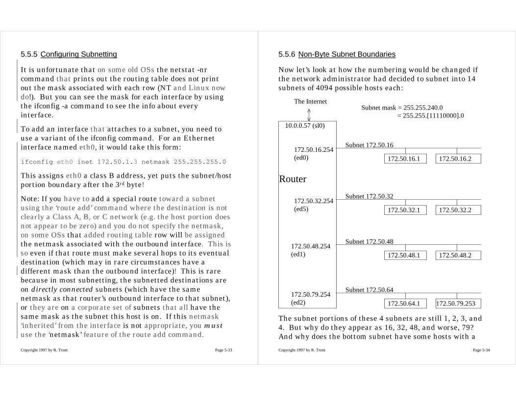
5.5.6 Non-Byte Subnet Boundaries
Now let’s look at how the numbering would be changed ifthe network administrator had decided to subnet into 14subnets of 4094 possible hosts each:
172.50.48.1 172.50.48.2
Subnet 172.50.48172.50.48.254(ed1)
Router
172.50.32.1 172.50.32.2
Subnet 172.50.32172.50.32.254(ed5)
172.50.16.1 172.50.16.2
Subnet 172.50.16172.50.16.254(ed0)
172.50.64.1 172.50.79.253
Subnet 172.50.64172.50.79.254(ed2)
10.0.0.57 (sl0)
The InternetSubnet mask = 255.255.240.0
= 255.255.[11110000].0
The subnet portions of these 4 subnets are still 1, 2, 3, and4. But why do they appear as 16, 32, 48, and worse, 79?And why does the bottom subnet have some hosts with a
Copyright 1997 by R. Tront Page 5-35
third byte of 64 and another with a third byte of 79? Youmust be able to figure on an exam why this is allowable!
Well, you have to think totally in binary. You need a tableof 0-255 in both binary and hex close at hand (I will provideor allow you to bring one to exams).
The router’s interface 172.50.79.254 is the highest legallyallowable numbered interface on the 172.50.64 sub-network:
172.50.[0100|1111].[11111110]
Notice the subnet number is 4, but when placed in theupper most nibble of the third byte this is 64. And the mostsignificant portion of the host portion adds another 15 toresult in 79! And the last byte is all one bits except for theleast significant bit. This is because if the last byte were255, the result would be a special reserved address forsubnet broadcasting (to be discussed later). Similarly thelowest legal address is given to one of the hosts 172.50.64.1:
172.50.[0100|0000].[00000001]
If the last bit were 0, this would look like a network addressrather than a host address.
Midterm practice:
• Try figuring what the largest and lowest addresses wouldbe on the other subnets.
• Or try subnetting differently (e.g. 62 subnets of 1022hosts).
• Or try subnetting a class C network!
• Or ponder whether a subnet can be subnetted.
Copyright 1997 by R. Tront Page 5-36
5.5.7 Subnetting Summary
In summary, subnetting allows:
• conservation of IP address space.
• reduction in size of tables needed in backbone routers.
• hierarchical organization and delegation within nets.
• abstraction so changes will not normally affect higherlevels in the hierarchy.
The drawbacks are:
• the routing algorithm is slowed by the masking.
• all routers and hosts which attach to subnets must havesubnet mask capable routing tables and algorithms (thisis pretty standard now in 1997). Hosts need subnetalgorithms, because there may be two routers on thathost’s LAN, one to each of two other subnets of the samenet. And the host should know which router to send eachkind of packet to. Rather than hard coding this into eachof a hundred host’s routing tables, each host could obtainthis by ICMP redirects if it made a mistake, or bylistening to routing protocol broadcasts from the routers.
• The hierarchy is a little stricter than you sometimeswant, and not all OSs provide ‘route add -netmask’ toallow you to bypass this hierarchy with unusual alternatepaths.
Copyright 1997 by R. Tront Page 5-37
Finally, in previous semester’s assignments, some studentswhen subnetting a network, thought they couldconceptually leave some hosts on the old net. This is notpossible! If you subnet a net into two subnets, all hostsmust be in assigned to either one or the other of thesubnets.
Copyright 1997 by R. Tront Page 5-38
5.6 Special Addresses
There are many special addresses in IP. Some are onlylegal as source IDs, others only as destination IDs, someonly have meaning in a routing table, and other only in apacket traversing the net.
You have already seen some of these special IDs.
• addresses whose host portion is all 0 bits are reallynetwork addresses.
• addresses that begin with 127 are really thelocalhost/loopback address.
• The address 0.0.0.0, when seen in the destination columnof a routing table means that is the default route row.BUT, when seen in a packet, it means ‘this’ host on ‘this’net. This latter situation is sometimes seen in RARPwhen a workstation is booting and doesn’t actually knowits IP address yet.
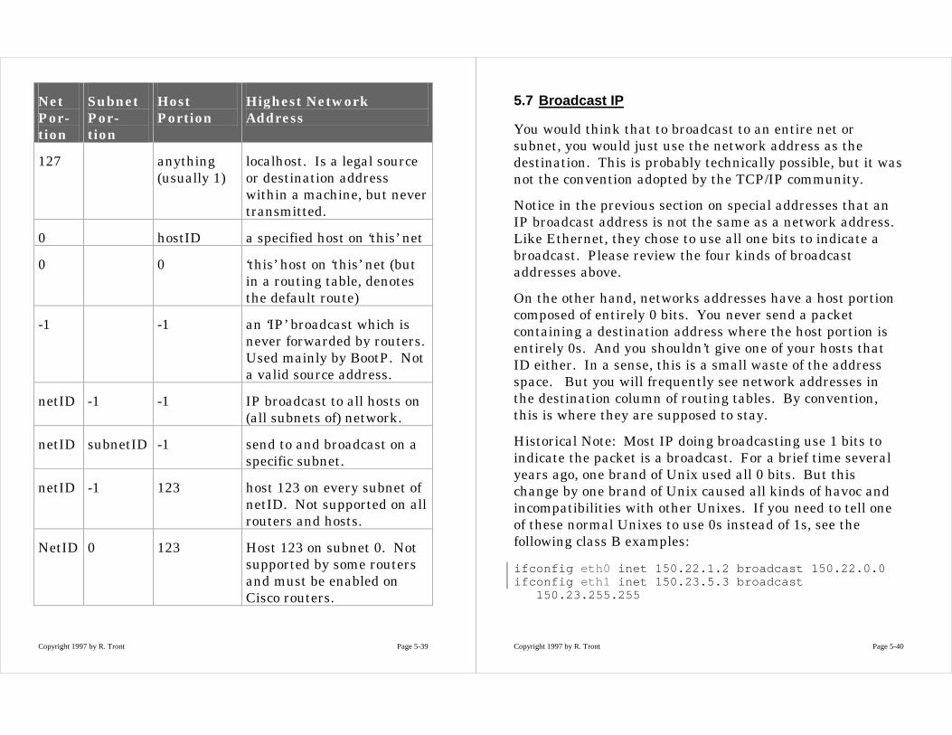
Here is a table that mentions some of these and more.
Note that by -1 in the table below, I mean entirely one bitsno matter how wide the field is (this width-independentabbreviation comes from 2’s complement!).
Also note that all 0s and entirely 1s are not usable as actualnetwork or host addresses, as they have the specialmeanings shown below. But a subnet address field of all 0sis allocatable as an actual subnet address (Why? Becauseyou either know your complete network address, or youdon’t and thus use 0s for net and subnet portion).
Copyright 1997 by R. Tront Page 5-39
NetPor-tion
SubnetPor-tion
HostPortion
Highest NetworkAddress
127 anything(usually 1)
localhost. Is a legal sourceor destination addresswithin a machine, but nevertransmitted.
0 hostID a specified host on ‘this’ net
0 0 ‘this’ host on ‘this’ net (butin a routing table, denotesthe default route)
-1 -1 an ‘IP’ broadcast which isnever forwarded by routers.Used mainly by BootP. Nota valid source address.
netID -1 -1 IP broadcast to all hosts on(all subnets of) network.
netID subnetID -1 send to and broadcast on aspecific subnet.
netID -1 123 host 123 on every subnet ofnetID. Not supported on allrouters and hosts.
NetID 0 123 Host 123 on subnet 0. Notsupported by some routersand must be enabled onCisco routers.
Copyright 1997 by R. Tront Page 5-40
5.7 Broadcast IP
You would think that to broadcast to an entire net orsubnet, you would just use the network address as thedestination. This is probably technically possible, but it wasnot the convention adopted by the TCP/IP community.
Notice in the previous section on special addresses that anIP broadcast address is not the same as a network address.Like Ethernet, they chose to use all one bits to indicate abroadcast. Please review the four kinds of broadcastaddresses above.
On the other hand, networks addresses have a host portioncomposed of entirely 0 bits. You never send a packetcontaining a destination address where the host portion isentirely 0s. And you shouldn’t give one of your hosts thatID either. In a sense, this is a small waste of the addressspace. But you will frequently see network addresses inthe destination column of routing tables. By convention,this is where they are supposed to stay.
Historical Note: Most IP doing broadcasting use 1 bits toindicate the packet is a broadcast. For a brief time severalyears ago, one brand of Unix used all 0 bits. But thischange by one brand of Unix caused all kinds of havoc andincompatibilities with other Unixes. If you need to tell oneof these normal Unixes to use 0s instead of 1s, see thefollowing class B examples:
ifconfig eth0 inet 150.22.1.2 broadcast 150.22.0.0ifconfig eth1 inet 150.23.5.3 broadcast
150.23.255.255
Copyright 1997 by R. Tront Page 5-41
The broadcast specification for ed1 above is not required if itis the default for that interface’s network. Also, forsubnetted networks, you would have to carefully specifyboth the netmask and the broadcast address in the ifconfigcommand, and be careful to specify a broadcast address thathad 1’s in only the correct (i.e. host portion) bits.
Copyright 1997 by R. Tront Page 5-42
5.7.1 Implementation of IP Broadcasting
Do not get IP broadcasting confused with Ethernet (MACLayer) broadcasting. Ethernet broadcasting can only travelas far as that particular Ethernet extends (possibly througha few repeaters or a bridge).
In contrast, IP broadcasting is an net layer concept.
• It allows someone in the marketing department of asubnetted firm to send a broadcast to the engineeringdepartment’s subnet, without it being broadcast to everydepartment in the corporation.
• And, it allows you to send a broadcast packet across theworld to some other corporation’s network and have itexplode into a broadcast to all hosts on that corporation’snetwork. And in addition, you did not broadcast to therest of the stations in the world. (Thankfully, there is noway to do a complete Internet-wide broadcast!).
It is obvious that this kind of broadcasting logic must belocated in the intranet or internet layers of a datacommunications system.
The exact implementation of IP broadcasting depends onthe particular type of intranet layer being used in thetargeted broadcast. In the beginning, the Internet wasexclusively a bunch of Unix hosts on Ethernetsinterconnected by modems. So IP broadcasts reaching afinal net were simply turned into Ethernet broadcasts bythe router connected to that final net. Now, there aresubnetting issues that must be handled by routers(particular, making multiple copies of the packet at the IP
Copyright 1997 by R. Tront Page 5-43
layer to forward in different directions to the differentsubnets of a particular net).
In addition, not all destination networks or subnetworkshave the physical broadcast capability that Ethernet has.To accommodate this, the router must get a list of everysingle host on the destination (sub)net, and send anindividual message to each one.
Copyright 1997 by R. Tront Page 5-44
5.7.2 Security Issues of IP Broadcasting
With IP broadcasting you could potentially send an IPpacket to Microsoft, say, and have it reach every singleMicrosoft Corporation machine! This is very different thanjust broadcasting to the local Ethernet you reside one. Inaddition, you could target a more specific part of Microsoft,by sending a broadcast to a specific subnet of Microsoft’snetwork. So for a hackers, these can be used as verycarefully targeted broadcast bombs.
Though some of these may be harmless, repeatedtransmissions of this type will clog up the destination netand bring its performance down to zero. In addition, itmight allow outsiders to find out the IP addresses of allhosts in a particular subnet of Microsoft (‘ping’ the subnetand note all the replies that come back). Then more specificattacks might begin once you know the actual address ofsome hosts.
Since net or subnet directed broadcasts are such a securityissue, it is important that network administrators programgateway routers to not let them in. This would be oneaspect of what is generically called a ‘firewall’.
Copyright 1997 by R. Tront Page 5-45
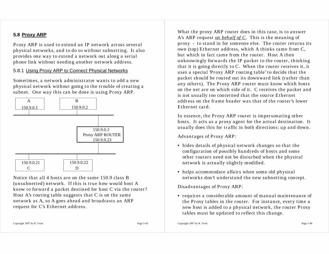
5.8 Proxy ARP
Proxy ARP is used to extend an IP network across severalphysical networks, and to do so without subnetting. It alsoprovides one way to extend a network out along a serialphone link without needing another network address.
5.8.1 Using Proxy ARP to Connect Physical Networks
Sometimes, a network administrator wants to add a newphysical network without going to the trouble of creating asubnet. One way this can be done is using Proxy ARP.
150.9.0.3Proxy ARP ROUTER
150.9.0.23
150.9.0.1
A B
150.9.0.2
150.9.0.21C
150.9.0.22D
Notice that all 4 hosts are on the same 150.9 class B(unsubnetted) network. If this is true how would host Aknow to forward a packet destined for host C via the router?Host A’s routing table suggests that C is on the samenetwork as A, so A goes ahead and broadcasts an ARPrequest for C’s Ethernet address.
Copyright 1997 by R. Tront Page 5-46
What the proxy ARP router does in this case, is to answerA’s ARP request on behalf of C. This is the meaning ofproxy - to stand in for someone else. The router returns itsown (top) Ethernet address, which A thinks came from C,but which in fact came from the router. Host A thenunknowingly forwards the IP packet to the router, thinkingthat it is going directly to C. When the router receives it, ituses a special ‘Proxy ARP routing table’ to decide that thepacket should be routed out its downward link (rather thanany others). The Proxy ARP router must know which hostson the net are on which side of it. C receives the packet andis not usually too concerned that the source Ethernetaddress on the frame header was that of the router’s lowerEthernet card.
In essence, the Proxy ARP router is impersonating otherhosts. It acts as a proxy agent for the actual destination. Itusually does this for traffic in both directions: up and down.
Advantages of Proxy ARP:
• hides details of physical network changes so that theconfiguration of possibly hundreds of hosts and someother routers need not be disturbed when the physicalnetwork is actually slightly modified.
• helps accommodate affairs when some old physicalnetworks don’t understand the new subnetting concept.
Disadvantages of Proxy ARP:
• requires a considerable amount of manual maintenance ofthe Proxy tables in the router. For instance, every time anew host is added to a physical network, the router Proxytables must be updated to reflect this change.

Copyright 1997 by R. Tront Page 5-47
• doesn’t work on non-broadcast nets which do not use ARP.
• doesn’t generalize well to topologies where multipleredundant routes/routers exist between the two physicalnets.
• may force administrators to turn off some securitysystems.
5.8.2 Security Issues of Proxy ARP
Actually, ARP itself is a security risk. It works onbroadcasting and trust. It trusts that an ARP reply isauthentic, and not from thief who is physically trying to‘spoof’ his way into the network.
Since Proxy ARP routers require a table lookup in order toreply to an ARP, some other attacking machine present onthe net could be hacked to reply to the ARP. By the timethe Proxy router replies with the real ARP reply, the sourceA has already received an ARP reply from the hacker’smachine and has unknowingly started sending the data tothe hacker’s machine!
Some security conscious ARP implementations monitortheir cache to make sure that there are not two IP addressesthat map to the same Ethernet address. If this happens,they report this inconsistency to the network administrator.But unfortunately, this is exactly what happens when ProxyARP is in use (Why? How?). Thus you cannot use ProxyARP with a system that has this monitoring, unless theadministrator can turn it off (or filter it out of her incomingmessage log).
Copyright 1997 by R. Tront Page 5-48
5.8.3 Using Proxy ARP For Serial Links
Every interface on every physical network generally needsan IP address. Unfortunately, some physical links onlyhave two computers attached to them: one at each end.This is very common for long haul inter-office connectionsover a modem.
But, it is silly to use a class C network number for such aphysical link as this uses up 254 valuable IP address whenonly two are needed. There are two solutions to thisunfortunate situation.
A. Proxy ARP -- make it part of one end’s network.
B. Subnetting
C. Network Address Translation (NAT) using the non-routable address ranges.
We will discuss the first solution in this section. On theother hand, there is a good example of the second in section3.7 of [Stevens94] which might make a good exam question.There is a tutorial paper on NAT athttp://www.cisco.com/warp/public/779/largeent/nat1_wp.htm#xtocid278552. NAT might be a good 471 Assignment #5project on either the router or FreeBSD. Also see RFC1631.
The trick in using Proxy ARP for this purpose is to makeboth the interfaces on the ends of the serial link be part ofthe one of the networks. In the diagram below, theinterfaces attached to each modem are both part of thelower network (i.e. have the network address 150.9!).

Copyright 1997 by R. Tront Page 5-49
150.9.0.3Proxy ARP ROUTER
150.9.0.23
133.55.0.1
X Y
133.55.0.2
150.9.0.21C
150.9.0.22D
150.9.0.4
Modem
Modem
If Host C wants to send to Host X or Y, the proxy routerworks as a standard router. It’s routing table forwards suchpackets to network 133.55 (or to the host specific route150.9.0.4) via its top interface. Also, Host Y must be able toact as a standard router for return traffic (recall that mostmachines with two interfaces are configured to do‘forwarding’).
On the other hand, if Host C wants to send a packet toeither end of the serial link, the lower interface of the ProxyARP router must do a ‘proxy’ and fake being one of theserial line’s IP addresses. For traffic from either serial
Copyright 1997 by R. Tront Page 5-50
interface headed to the lower network, the lower router justdoes standard simple routing.
Note if using serial lines and a null modem between twohome computers, one of which is being used further as agateway to an Internet ISP or to SFU, you can’t use proxyARP! This is because the serial link between your two homecomputers is not Ethernet semi-broadcast based. It doesn’tuse the ARP mechanism at all! In this situation, you wouldhave to use IP Masquarading (which is sometimes calledNetwork Address Translation (NAT) or IP ‘aliasing’.

Copyright 1997 by R. Tront Page 5-51
5.9 Supernetting
5.9.1 Motivation for Supernetting
Earlier when discussing the reasons behind subnetting, wesuggested that the Internet was running out of class Baddresses. Given that the InterNIC can’t justify giving outClass B network addresses to small firms that will neverneed more than 1000 host addresses, they would tend togive such a company 4 Class C network addressescontaining about 1024 host addresses.
Actually, they generally gave such a small company just oneClass C address. But as the company grew, it asked foranother, and then another. Unfortunately, every backbonerouter of the Internet must contain a routing table thatcontains every network address in use on the Internet. Sosuch a company would now use up 3 or 4 rows of routingtable space in every backbone router.
It was soon realized that this would eventually slow thebackbone down and increase the routing table spacerequirements. I suspect that the backbone routers use bothdisk and RAM space for tables, with the most recently usedrows cached in RAM (possibly even accessed by hashingalgorithms?).
Copyright 1997 by R. Tront Page 5-52
5.9.2 Grouping Network Addresses into Supernets
It was also realized that if they could allocate a bunch ofclass C networks at contiguous network addresses, theycould use netmasks for supernetting. Let’s look at anexample. Say you have a company with 400 hosts whichwants to attach to the Internet. They need at least twoclass C network addresses or a class B address. But a classB network address contains 64K host addresses, far morethan the company will ever need. The solution is to allocatethem 4 or 8 class C addresses which have adjacentaddresses and whose high order network address bits are allidentical. E.g.
200.33.[10100100].x200.33.[10100101].x200.33.[10100110].x200.33.[10100111].x
Notice that the criterion italicized about is slightly morestrong than the addresses being contiguous. Contiguous byitself is not adequate. But given this special criterion, thebackbone routers need only have one routing table rowwhich will encompass these 4 class C addresses. The rowwould look like:
200.33.[10100100].0 with netmask 255.255.[11111100].0
which is:
200.33.164.0 with netmask 255.255.252.0
(Note I have left the gateway column out). Anyway, this ispretty cool. So now not only are the individual networksusing internal hierarchies (subnets), but also the backbone

Copyright 1997 by R. Tront Page 5-53
has finally gotten with it, and is taking some advantage ofthe hierarchical principle.
5.9.3 CIDR and Internet Service Providers
The result is called Classless Internet Domain Routing(CIDR). First, it overrides some of the assumptions that aremade when strictly observing the class A/B/C byte boundaryand routing algorithm details. And second, it is a domainrouting system. That means it concerns itself only withmajor address domains that are of interest to the backbone.The term CIDR is not meant to be associated withsubnetting within particular networks, even though it usesan almost identical masking principle. You will see later inthe course, though, that the backbone has differentresponsibilities and even uses different routing protocolsthan do individual networks.
One of the nice things about hierarchies, is it allowsdelegation of responsibilities to subsystem. Consider aninternet service provider (ISP). Such a company providesinternet connections to other companies. Using CIDR, theInterNIC can provide a set of class C or even a set of class Baddresses to an ISP, and the ISP can hand them out toindividual companies that buy Internet service from theISP. When an individual company applies to the ISP, theISP can give them a network address without bothering theInterNIC, and without needing changes in the backbonerouting tables. The ISP typically also makes sure theindividual company’s symbolic address (e.g. astroflight.com)gets listed on the backbone Domain Name Service. TheDNS stores the network IP address of each company, butthe backbone routers only need one entry and one CIDRnetmask for all the companies that buy the connectivity
Copyright 1997 by R. Tront Page 5-54
from that particular ISP. If I am going to send 1000 packetsto astroflight.com, I need one lookup in the rather longbackbone DNS tables, and then send 1000 packets throughthe backbone routers which can have much shorter tablesbecause of CIDR.
You can see in action here two principles of computerscience:
• First get it right, then make it fast. The Internet hasdeveloped over several decades, and was not perfect butworked. But as it aged and grew, they were able toaccommodate the growth and find ways to speed it up.
• To make it fast, speed up the things that will make thebiggest improvement in speed. Generally, those are thethings that are done most frequently (e.g. those which areexecuted inside loops or doubly nested loops).

Copyright 1997 by R. Tront Page 5-55
5.10 References
[Comer00] “Internetworking with TCP/IP, Vol. 1, 4rd Ed” byDouglas E. Comer, Prentice-Hall, 2000.
[Stevens94] “TCP/IP Illustrated, Vol. 1” by W. RichardStevens, Addison-Wesley, 1994.