5 Gear units, types of installation, lubricant...
30
26
Transcript of 5 Gear units, types of installation, lubricant...

26

5 Gearunits,typesofinstallation,lubricantquantities
5.1 Standardfittingpositions/typesofinstallationforBauergearedmotors
27
5
28

The standard position of the terminal box for helical-gear and shaft- mounted geared mo-tors is position I. Cables may be introduced from side A or C..
5.2 Positionoftheterminalboxandthecableentrypoints(BGandBF)
5.2 Positionoftheterminalboxandthecableentrypoints(BGandBF)
Turning or rotating the gearbox in space in the different mounting positions according to DIN 42950 does not influence the marking as shown. The details of the terminal box always show the position of the terminal box and the cable entry in relation to the gearbox and not in space. The mounting according to DIN 42950 is to be given separately.
29
5

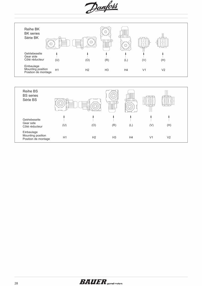
The standard position of the terminal box for bevel-geared and worm- geared motors is position II. This is the arrangement which affords the lowest profile for the bevel-geared motor.
Cable entry through side A or side C is possible
5.3 Positionoftheterminalboxandthecableentrypoints(BKandBS)
5.3 Positionoftheterminalboxandthecableentrypoints(BKandBS)
Turning or rotating the gearbox in space in the different mounting positions according to DIN 42950 does not influence the marking as shown. The details of the terminal box al-ways show the position of the terminal box and the cable entry in relation to the gearbox and not in space. The mounting according to DIN 42950 is to be given separately.
30
The output shafts and output-shaft bearings are matched to the motor torques. It is advis-able to locate the drive-transmission element‘s point of application as close as possible to the shaft collar to ensure that the load imposed by external radial forces is not unneces-sarily high. Permissible values for radial forces referred to the output shaft centreline are listed in the selection tables. Please consult us if your application involves extra-high axial loading.
Output shaft and second shaft stub, keyway and key are in compliance with the DIN stand-ards and ISO fits listed below:
SolidshaftShaft diameter to D = 50 mm in ISO k6 (DIN 748 Page1)
as of D = 50 mm in ISO m6 (DIN 748 Page 1)Keyway ISO P9 (DIN 6885 Page 1)Key, height ISO h9 (DIN 6885 Page 1 and DIN 6880)Bore - customer ISO H7
HollowshaftwithkeywayBore diameter ISO H7 (DIN 748)Keyway ISO JS9 (DIN 6885 Page 1)Key, height ISO h9 (DIN 6885 Page 1 and DIN 6880)Customer shaft ISO h6
Hollowshaftforshrink-ondisccoupling(SSV)Outside diameter ISO f7Inside diameter ISO H7Customer shaft ISO h6
Note: Gearboxes using torque reaction by means of a flange (Code 2.; 3; 4.; 7.; 8.) or torque arm (Code 5.), must have the side for the torque reaction the same as where the radial force on the output shaft occurs (see rubber buffers for torque arms)! Please consult the factory for other designs.
Always exercise meticulous care when fitting transmission elements onto output shafts and, whenever possible, use the DIN 332 tapped bore provided for this purpose. Fitting is usually easier if the transmission element can be heated to approximately 100° C for instal-lation. Dimension the locating bore to ISO H7.
Gears with solid shaft at each end (gear code -.3/): alignment of the two keys is subject to the DIN 7168 tolerances, the degree of accuracy is “fine”.
Hollow shafts usually engage solid shafts of the driven machinery. The gear unit must be mounted such as to be free of constraint and be fixed axially (e.g. by means of assembly help acc. to chapter 5.8). Special contract provision must be made if the hollow shaft has to guide the solid shaft or, for any other reason, close out-of-round tolerance referenced to a point on the gear housing (such as a flange, for instance) is required.
A shrink disc coupling (SSV) can transmit high torque from the non- grooved hub to the smooth shaft. The SSV is easily secured and released, using commercially available bolts. SSVs are the ideal supplement for shaft mount gears. The maximum transmittable torque for the selected shrink discs when fitted and mounted according to instructions is above the breakaway torque of the respective motors classified as standard (for classification of shrink disc sizes see 11.4.1, 12.4.1, 13.4.1)
5.4 Radialandaxialforcesattheoutputshaft
5.4 Radialandaxialforcesattheoutputshaft
5.5 Dimensionsandfitsofoutputshaftsandkeyways
5.5 Dimensionsandfitsofoutputshaftsandkeyways
5.6 Installingtransmissionelements
5.6 Installingtransmissionelements
5.6.1 Gearwithsolidshaft5.6.1 Gearwithsolidshaft
5.6.2 Gearwithhollowshaft5.6.2 Gearwithhollowshaft
5.6.3 Shrinkdisccoupling5.6.3 Shrinkdisccoupling
31
5

Detailed information on shaft-mounted gear units, bevel-gear units and worm-gear units is available (see 11.4.3, 12.5.3, 13.5.3).
The lifetime of the gearbox lubricant is increases the better it is protected from negative environmental influences. Should the oil level or the gearbox ratio cause a very high lubri-cant temperature, the gearbox will be supplied as standard with a breather plug. Either on request or for corresponding high ambient temperatures, all gearboxes as from size 10 can be supplied with a breather plug.
For the position of the threaded plugs see 5.13
All size 10 and larger gears are available with double seals for the output shaft on request and at extra cost. Double seals are particularly effective if the output shaft points down and as protection against external influences
5.9 Gearventilation5.9 Gearventilation
5.10 Outputshaftseals5.10 Outputshaftseals
Shaft-mounted geared motors require a suitable torque restraint to resist the reaction torque. Shaft-mounted gears have cast torque arms as standard. Bevel gears and worm gears are available with bolt-on torque arms on request. The torque arm is screwed onto the front V on the side of the gear unit (see dimensional drawings 11.3, 12.3, 13.3). It is always important to ensure that the torque arm does not create excessive constraining forces due to the driven shaft running untrue, for example. Excessive play can result in ex-cessive shock torques in switching or reversing operations. Consequently, we recommend the use of pre-tensioned rubber damping elements. These rubber buffers are part of the scope of supply for designs with a torque arm (see 11.4.2, 12.4.2, 13.4.2)
(1) Attachingthehollowshafttothecustomershaft Threaded bolt (d) is screwed into the end thread of the shaft to be driven. By tightening
the nut, apply force to thrust plate (b) and locating ring (c) to draw the gear unit onto the shaft.
(2) Axialfastening Pressure piece (b) is rotated and fitted against retaining ring (c) using fixing screw (a).
(3) Removing Extractor (f ) is fitted between the end face of the shaft and retainer ring (c). Tighten
press-off screw (e) against the end of the shaft and pull the gear unit off the shaft. Manufacturing drawings for the required parts are available on request. These parts are
not included in the scope of supply.
5.7 Torquerestraint5.7 Torquerestraint
5.8 Notesforinstallingshaftmountgearswithhollowshaftandkeyway
5.8 Notesforinstallingshaftmountgearswithhollowshaftandkeyway
32
The drives are shipped ready-filled with gear lubricant. Lubricated in this way, the gear units are suitable for ambient temperatures in the range -20°C to + 40°C. The quantity of lu-bricant is optimised for the desired installed position as is stated in the motor rating plate. The type of lubricant is stated in the Operating Instructions. Lubricants for other tempera-ture ranges or special applications available on request.
Wear-protective EP gear oils as indicated in the following table have proved particularly effective:
5.11 Lubricants5.11 Lubricants
Lubricant Lubricanttype
Manufacturer MineralOilCLP220
SyntheticOilPGLP220
SyntheticOilPGLP460
SyntheticOilPGLP68
USDAH1Oil
Standard oil for gearboxes in the seriesBF,BG,BK60-BK90
Standard oil for gearboxes in the seriesBS02-BS10,BK06-BK10,BM09-BM10High temperature oil for gearboxes in the seriesBF,BG,BK10,BK60-BK90,BS02-BS10,BM09-BM10
Standard oil for gearboxes in the seriesBS20-BS40,BK20-BK50,BM30-BM40High temperature oil for gearboxes in the seriesBS20-BS40,BK20-BK50,BM30-BM40
Low temperature oil for gearboxes in the seriesBF,BG,BK,BM,BS
Food and Beverage In-dustry Oil for gearboxes in the seriesBF,BG,BK,BM,BS
AGIP Blasia 220
ARAL Degol BMB 220Degol BG 220
Degol GS 220 Degol GS 460 Eural Gear 220
BECHEM RHUS Staroil SMO 220
BP Energol GR-XP 220 Enersyn SG-XP 220 Enersyn SG-XP 460
CASTROL Alpha SP 220Hypoy EP 90
Alphasyn PG 220 Alphasyn PG 460
DEA Falcon CLP 220
ESSO Spartan EP 220GP 90
FUCHS Renolin CLP 220Renolin CLPF 220 Super
Renolin PG 220 Renolin PG 460 Renolin PG 68
HOUGHTON Molygear 220
KLÜBER Klüberoil GEM 1-220 Syntheso HT 220Klübersynth GH 6-220
Syntheso HT 460Klübersynth GH 6-460
Syntheso HT 68 Klübersynth GH 6-80
Klüberoil 4UH1-220N
MOBIL Mobilgear 630Mobilube GX 85 W-90A
Glygoyle HE 220Glygoyle 30
Glygoyle HE 460
OEST Gearol C-LP 220
OPTIMOL Optigear 220 Optiflex 220 Optiflex 460 Optileb 220
SHELL Omala Oil 220 Tivela WB Tivela S220 Tivela SD Tivela S460 Cassida Fluid GL 220
TEXACO Geartex EP-A SAE 85W-90
TOTAL Carter EP 220
WINTERSHALL Ersolan 220
Important:Synthetic gear oils of a Polyglykol base (e.g. PGLP…) must be disposed of separately to mineral oil as SpecialWaste .
So long as the ambient temperature does not fall below – 20 °C the international definition of the viscosity class at 40 °C according to ISO 3448 and DIN 51519 ISO the viscosity class VG220 (SAE90) is recommended according, in North America AGMA 5EP.
For lower temperatures it is recommended to use oils of a lower nominal viscosity with a corresponding better starting characteristic, for instance a PGLP with a nominal viscosity VG68 (SAE80) or AGMA 2EP respectively. These types of oil can already be necessary at a temperature around the freezing point, if the break away torque of a drive is reduced by some smooth starting device or if the motor has a relatively low power
The preferred quantity of lubricant for the planned type of installation is stated on the mo-tor‘s rating plate (symbol “oil can”). When topping up care should be taken to ensure that, depending on the fitting position, gearwheels and rolling contact bearings positioned at the top are also properly oiled. In special versions the oil level mark should be noted. Information about the quantity of lubricant required for other types of installation can be obtained from the factory
5.12 Lubricantquantities5.12 Lubricantquantities
33
5
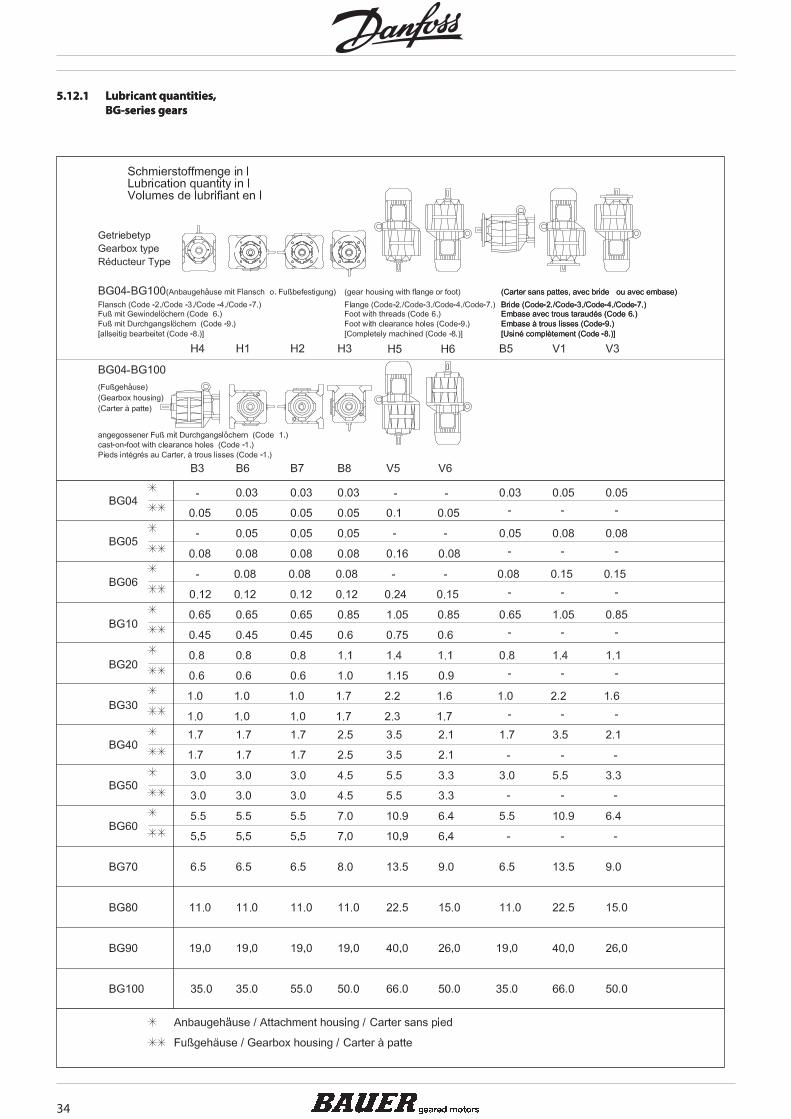
5.12.1 Lubricantquantities,BG-seriesgears
5.12.1 Lubricantquantities,BG-seriesgears
34
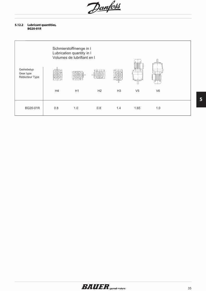
5.12.2 Lubricantquantities,BG20-01R
5.12.2 Lubricantquantities,BG20-01R
35
5

5.12.3 Lubricantquantities,BF-seriesgears
5.12.3 Lubricantquantities,BF-seriesgears
36

5.12.4 Lubricantquantities,BK-seriesgears
5.12.4 Lubricantquantities,BK-seriesgears
37
5

5.12.5 Lubricantquantities,BS-seriesgears
5.12.5 Lubricantquantities,BS-seriesgears
38
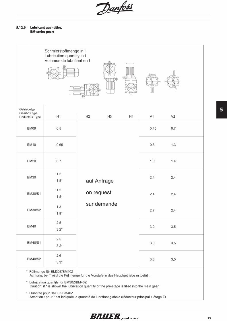
5.12.6 Lubricantquantities,BM-seriesgears
5.12.6 Lubricantquantities,BM-seriesgears
39
5

5.12.7 Lubricantquantities,pre-stagegears(Z))
5.12.7 Lubricantquantities,pre-stagegears(Z))
40

5.12.8 Lubricantquantities,intermediategears
5.12.8 Lubricantquantities,intermediategears
41
5
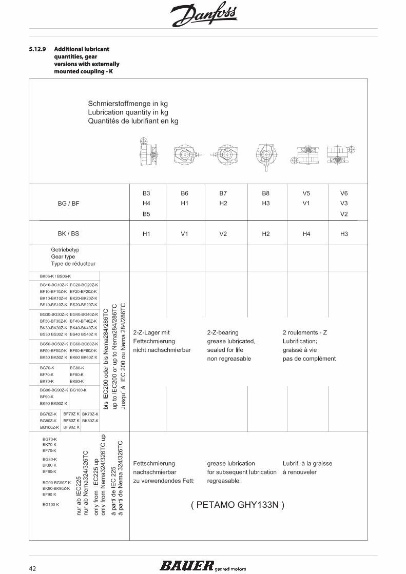
5.12.9 Additionallubricantquantities,gearversionswithexternallymountedcoupling-K
5.12.9 Additionallubricantquantities,gearversionswithexternallymountedcoupling-K
42
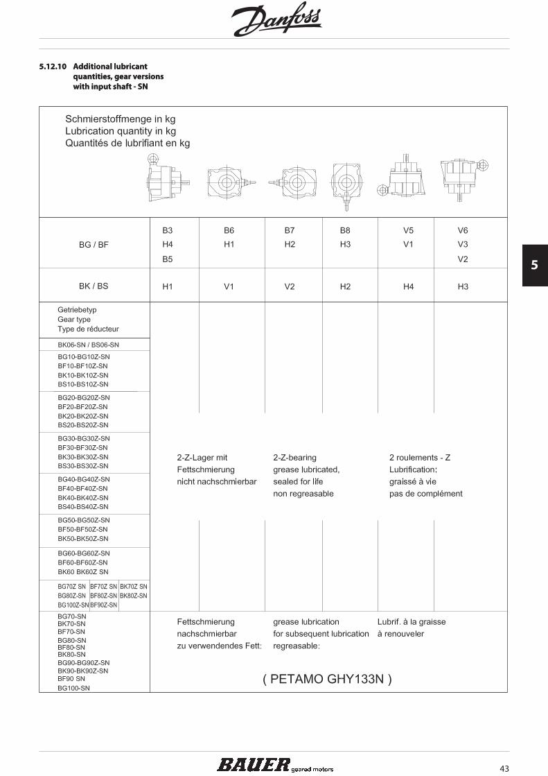
5.12.10 Additionallubricantquantities,gearversionswithinputshaft-SN
5.12.10 Additionallubricantquantities,gearversionswithinputshaft-SN
43
5

5.13 Positionofthreadedplugs
5.13 Positionofthreadedplugs
5.13.1 Positionofthreadedplugs,BG-seriesgears
5.13.1 Positionofthreadedplugs,BG-seriesgears
M* = Factor and position of the drain plug on the system cover, see 5.13.10.
44

5.13.2 Positionofthreadedplugs,BG20-01R
5.13.2 Positionofthreadedplugs,BG20-01R
M* = Factor and position of the drain plug on the system cover, see 5.13.10.
45
5

5.13.3 Positionofthreadedplugs,BF-seriesgears
5.13.3 Positionofthreadedplugs,BF-seriesgears
M* = Factor and position of the drain plug on the system cover, see 5.13.10.
46
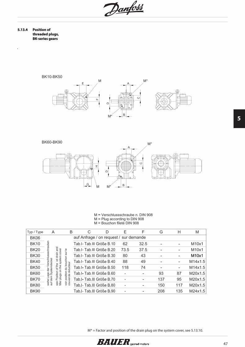
5.13.4 Positionofthreadedplugs,BK-seriesgears
5.13.4 Positionofthreadedplugs,BK-seriesgears
M* = Factor and position of the drain plug on the system cover, see 5.13.10.
47
5
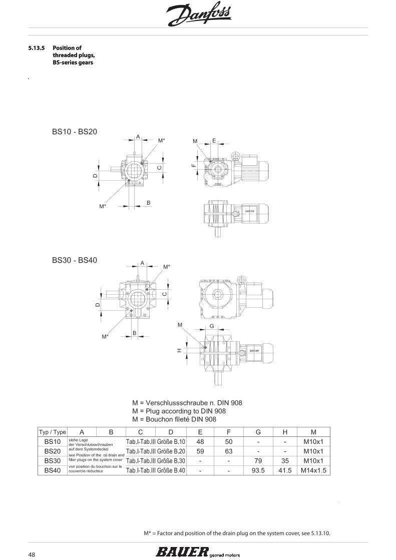
5.13.5 Positionofthreadedplugs,BS-seriesgears
5.13.5 Positionofthreadedplugs,BS-seriesgears
M* = Factor and position of the drain plug on the system cover, see 5.13.10.
48
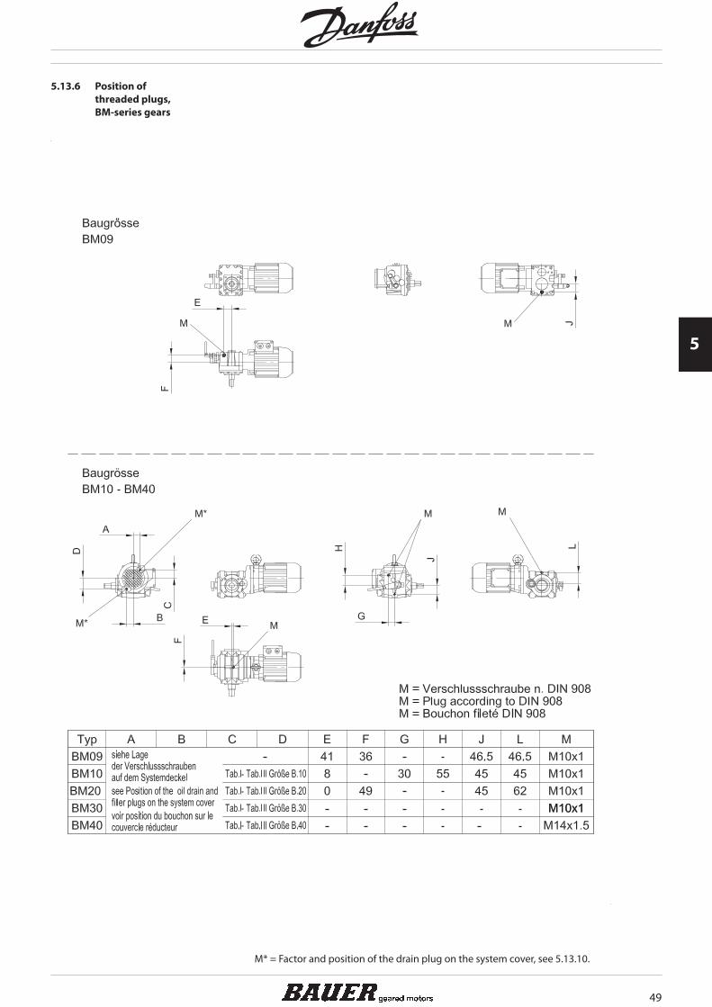
5.13.6 Positionofthreadedplugs,BM-seriesgears
M* = Factor and position of the drain plug on the system cover, see 5.13.10.
49
5

5.13.7 Positionofthreadedplugs,pre-stagegears(Z)
5.13.7 Positionofthreadedplugs,pre-stagegears(Z)
M* = Factor and position of the drain plug on the system cover, see 5.13.10.
50
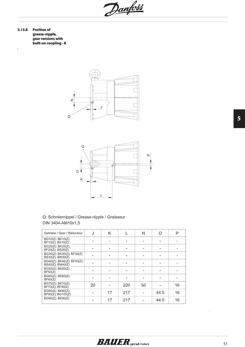
5.13.8 Positionofgrease-nipple,gearversionswithbuilt-oncoupling-K
5.13.8 Positionofgrease-nipple,gearversionswithbuilt-oncoupling-K
51
5

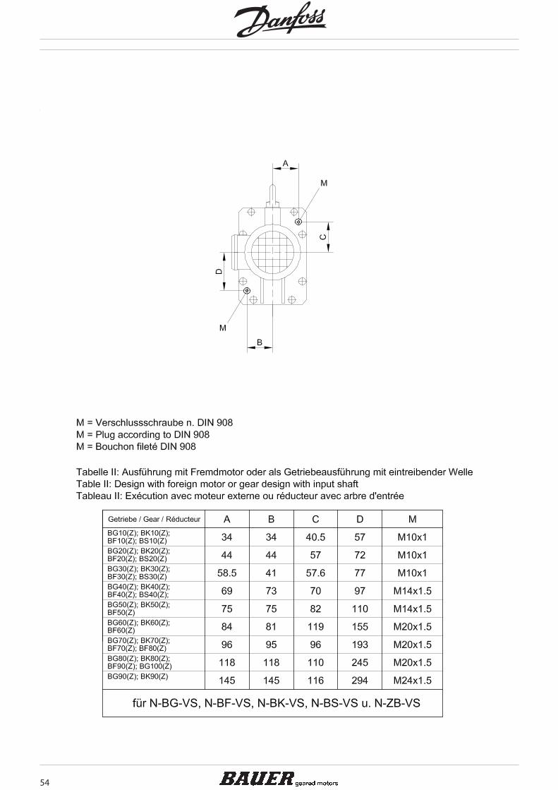
5.13.9 Positionofgrease-nipple,gearversionswithinputshaft-SN
5.13.9 Positionofgrease-nipple,gearversionswithinputshaft-SN
52

5.13.10 Positionofthreadedplugsonthesystemcover
5.13.10 Positionofthreadedplugsonthesystemcover
53
5
54

55
5