5. Foundation Selection - FEMA.gov · PDF file5. Foundation Selection ... for gravity loading,...
14
RECOMMENDED RESIDENTIAL CONSTRUCTION FOR COASTAL AREAS 5- 5. Foundation Selection This chapter provides foundation designs, along with the use of the drawings in Appendix A, to assist the homebuilder, contractor, and local engineering professional in developing a safe and strong foundation. Foundation design types, foundation design considerations, cost estimating, and details on how to use this manual are presented. 5.1 Foundation Design Types The homebuilder, contractor, and local engineering professional can utilize the designs in this chapter and Appendix A to construct residential foundations in coastal areas. The selection of appropriate foundation designs for the construction of residences is dependent upon the
Transcript of 5. Foundation Selection - FEMA.gov · PDF file5. Foundation Selection ... for gravity loading,...

RECOMMENDED RESIDENTIAL CONSTRUCTION FOR COASTAL AREAS 5-�
5.FoundationSelectionThis chapter provides foundation designs, along with the use of the drawings in Appendix A, to assist the homebuilder, contractor, and local engineering professional in developing a safe and strong foundation. Foundation design types, foundation design considerations, cost estimating, and details on how to use this manual are presented.
5.1 FoundationDesignTypes
The homebuilder, contractor, and local engineering professional can utilize the designs in this chapter and Appendix A to construct residential foundations in coastal areas. The selection of appropriate foundation designs for the construction of residences is dependent upon the

5-� Building on strong and safe foundations
5 foundation selection
coastal zone, wind speed, and elevation requirements, all of which have been discussed in the previous chapters. The following types of foundation designs are presented in this manual:
Open/Deep Foundations
n Braced timber pile (Case A)
n Steel pipe pile with concrete column and grade beam (Case B)
n Timber pile with concrete column and grade beam (Case C)
n Timber pile with concrete grade and elevated beams and concrete columns (Case H)
Open/Shallow Foundations
n Concrete column and grade beam (Case D)
n Concrete column and grade beam with slab (Case G)
Closed/Shallow Foundations
n Reinforced masonry – crawlspace (Case E)
n Reinforced masonry – stem wall (Case F)
Each of these foundation types designed for coastal areas have advantages and disadvantages that must be taken into account. Modifications to the details and drawings might be needed to incorporate specific home footprints, elevation heights, and wind speeds to a given foundation type. Consultation with a licensed professional engineer is encouraged prior to beginning con-struction.
The foundation designs and materials specified in this document are based on principles and practices used by structural engineering professionals with years of coastal construction experi-ence. This manual has been prepared to make the information easy to understand.
Guidance on the use of the foundation designs recommended herein is provided in Appendix B. Examples of how the foundation designs can be used with some of the homes in the publica-tion A Pattern Book for Gulf Coast Neighborhoods are presented in Appendix B. Design drawings for each of the foundation types are presented in Appendix A, and any assumptions used in these designs are in Appendix C.
5.2 FoundationDesignConsiderations
The foundation designs proposed are suitable for homes with dimensions, weights, and roof pitches within certain ranges of values. A licensed professional engineer should confirm the appropriateness of the foundation design of homes with dimensions, weights, or roof
pitches that fall outside of those defined ranges.

5-�RECOMMENDED RESIDENTIAL CONSTRUCTION FOR COASTAL AREAS
foundation selection 5
Most of the foundation designs are based on a �4-foot wide (maximum) by �4-foot deep (mini-mum) “module” (Figure 5-�). From this basic building block, foundations for specific homes can be developed. For example, if a �0-foot deep by 4�-foot wide home is to be constructed, the foundation can be designed around three �4-foot wide by �0-foot deep sections. If a �4-foot deep by 50-foot wide home is desired, four ��.5-foot wide by �4-foot deep sections can be used. If a ��-foot deep home is desired, the foundation designs presented here should only be used after a licensed professional engineer determines that they are appropriate since the shallow depth of the building falls outside the range of assumptions used in the design.
Figure5-1.Schematicofabasicmoduleandtwofootprints.
The licensed professional engineer should also consider the following:
n Local soil conditions. The pile foundations have been developed for relatively soft subsur-face soils. For driven treated lumber piles, the presumptive allowable working load values of 7 tons per pile gravity, 4.65 tons per pile uplift, and � tons per pile lateral were used. For steel pipe piles, the presumptive allowable working load piles were greater (�0 tons per pile for gravity loading, 6.7 tons per pile for uplift, and 4 tons per pile for lateral loading). Soil testing on the site should also be considered to validate the assumptions made.
In some areas of the coastal U.S. (e.g., portions of Louisiana), soils may exist that will not provide the presumptive pile values. In those areas, aspects of the FEMA 550 deep

5-4 Building on strong and safe foundations
5 foundation selection
foundation designs are still valid, but geotechnical engineers will need to be involved in por-tions of the design to determine required pile parameters. In poor soils, additional piles may need to be installed or long piles may need to be driven; however, the portions of the designs from the grade beams upward should remain valid.
The FEMA 550 shallow foundations are based on a presumptive bearing capacity of �,500 psf. This value is consistent with the presumptive bearing capacity of Section �806 of the �009 IBC for clay, sandy clays, clayey silts, and sandy silts (CL, ML, MH, and CH soils). In areas where soils will not provide this presumed bearing capacity, the shallow FEMA 550 de-signs should not be used until their ability to support the required loads can be confirmed by design professionals.
n Building weight. The foundations have been designed to resist uplift forces resulting from a relatively light structure. If the actual home is heavier (e.g., from the use of concrete com-posite siding or steel framing), it may be cost-effective to reanalyze and redesign the footings. This is particularly true for a home that doesn’t need to be elevated more than several feet or has short foundation walls that can help resist uplift.
n Footprint complexity. By necessity, the foundations have been designed for relatively simple rectangular footprints. If the actual footprint of the home is relatively complex, the engineer may need to consider torsional wind loading, differential movement among the “modules” that make up the home, concentrated loading in the home’s floor and roof diaphragms, and shear wall placement.
5.3 CostEstimating
Cost information that homebuilders can use to estimate the cost of installing the founda-tion systems proposed in this manual are presented in Appendix E. These cost estimates are based on May �006 prices from information provided by local contractors for the First
Edition of this manual.
5.4 HowtoUseThisManual
The rest of this chapter is designed to provide the user with step by step procedures for the information contained in this manual.
1. Determine location of the dwelling on a general map. Identify the location relative to key features such as highways and bodies of water. An accurate location is essential for using flood and wind speed maps in subsequent steps of the design process.
2. Determine location of dwelling on the appropriate FIRM
n Determine the flood insurance risk zone from the FIRM (Select V zone, Coastal A zone, non-Coastal A zone, or other). Refer to FEMA �58, Guide to Flood Maps, How to Use Flood Maps to Determine Flood Risk for a Property, for instructions.

5-5RECOMMENDED RESIDENTIAL CONSTRUCTION FOR COASTAL AREAS
foundation selection 5
n Determine the BFE or the interim Advisory Base Flood Elevations (ABFEs) for the location from the FIRM. If the dwelling is outside of flood-prone areas, flood loads do not need to be considered.
3. Identify the local building code. Several states and municipalities in coastal areas are adopt-ing new building codes to govern residential construction. This manual assumes that the IRC governs the design and construction requirements.
4. Identify the local freeboard requirements and DFE. Using either the local building codes, local floodplain ordinances, data obtained from local building officials, or personal preferenc-es (only if greater than minimum requirements), determine the minimum freeboard above the BFE or ABFE. The DFE is the sum of the BFE or ABFE and freeboard values.
5. Determine the required design wind velocity. The �006 and �009 IRCs reference ASCE 7-05 as the source of the wind speed information.
6. Establish the topographic elevation of the building site and the dwelling. Elevations can be obtained from official topographic maps published by the National Geodetic Survey (NGS) and/or as established or confirmed by a surveyor.
FIRM Panel No. ____________________
Flood Insurance Risk Zone ____________________
Base Flood Elevation (BFE) or Advisory Base Flood Elevation (ABFE) ____________________
County/Parish/City ____________________
Building Code ____________________
Building Code Date ____________________
Base Flood Elevation (BFE) or Advisory Base Flood Elevation (ABFE) ______________
Freeboard + ______________
Design Flood Elevation (DFE) ______________
Design Wind Velocity ______________________________
Wind Exposure Category ______________________________

5-6 Building on strong and safe foundations
5 foundation selection
n If the dwelling and its surrounding site are above the DFE, no flood forces need to be considered.
n If the desired topographic elevation is below the DFE, the dwelling must be elevated above the BFE or ABFE.
7. Determine the height of the base of the dwelling above grade. Subtract the lowest ground elevation at the building from the lowest elevation of the structure (i.e., bottom of lowest hori-zontal structural member).
8. Determine the general soil classification for the site. For shallow foundations, confirm that the soils on site have a minimum bearing capacity of �,500 psf. If soils lack that minimum ca-pacity, contact a geotechnical engineer and/or a structural engineer to confirm that the FEMA 550 foundation solutions are appropriate.
For deep foundations, confirm that the presumptive pile capacities (for gravity loads, uplift loads, and lateral loads) are achievable. If soils present on site will not support the presumed pile capacities, contact a geotechnical engineer and/or a structural engineer to determine ap-propriate pile plans.
9. Estimate erosion and scour. Estimate accumulated erosion and episodic scour over the life of the structure. Use accumulated erosion to determine eroded grade elevation and use ac-cumulated erosion and episodic scour to determine the foundation depth required to ensure shallow foundations will not be undermined.
10. Determine the type of foundation to be used to support the structure. Depending on the location of the dwelling, design wind speed, and local soil conditions documented above, select the desired or required type of foundation. Note that more than one solution may be possible. Refer to Chapter 4 for the potential foundation designs that can be used within the flood zones determined from the FIRM maps. Drawings in Appendix A illustrate the construction details for
Design Flood Elevation (DFE) ______________________________
Topo Elevation ______________________________
Elevation Dimension ______________________________
Soil Classification ______________________________
Source of Topo Elevation ______________________________
Topo Elevation (Site) ______________________________

5-7RECOMMENDED RESIDENTIAL CONSTRUCTION FOR COASTAL AREAS
foundation selection 5
each of the foundations. Refer to the drawings for further direction and information about the needs for each type of unit.
11. Evaluate alternate foundation type selections. The choice of foundation type may be on the basis of least cost or to provide a personal choice, functional, or aesthetic need at the site. Refer to Appendix E for guidance on preparing cost estimates. Functional needs such as pro-visions for parking, storage, or other non-habitable uses for the area beneath the living space should be considered in the selection of the foundation design. Aesthetic or architectural issues (i.e., appearance) also must be included in the evaluation process. Guidance for the architec-tural design considerations can be obtained from A Pattern Book for Gulf Coast Neighborhoods by the Mississippi Governor’s Commission on Recovery, Rebuilding and Renewal (see Appendix B) and from many other sources.
As part of the final analysis, it is strongly recommended that the selection and evaluation pro-cess be coordinated with or reviewed by knowledgeable contractors or design professionals to arrive at the best solution to fulfill all of the regulatory and functional needs for the construc-tion.
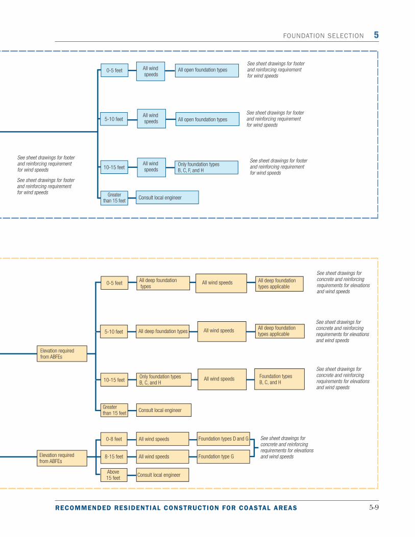
12. Select the foundation design. If the home’s dimensions, height, roof pitch, and weight are within the ranges used to develop these designs, the foundation designs can be used “as is.” However, if the proposed structure has dimensions, height, roof pitch, or weights that fall outside of the range of values used, a licensed professional engineer should be consulted. The materials presented in the appendices should help reduce the engineering effort needed to de-velop a custom design. Figure 5-� is a foundation selection decision tree for determining which foundation design to use based on the requirements of the home. Tables 5-�a and 5-�b show which foundation design cases can be used for one- and two-story homes, respectively, based on height of elevation and wind velocity.
Because the designs are good for a range of buildings, they will be conservative for some ap-plications. A licensed professional engineer will be able to provide value engineering and may produce a more efficient design that reduces construction costs.
5.5 DesignExamples
The foundation designs were developed to allow a “modular approach” for developing foundation plans. In this approach, individual rectangular foundation components can be assembled into non-rectangular building footprints (see Figures 5-� through 5-5). Ap-
pendix D provides detailed calculations and analysis for open and closed foundation designs. There are, however, a few rules that must be followed when assembling the modules:
1. The eave-to-ridge dimension of the roof is limited to 23 feet. The upper limit on roof height is to limit the lateral forces to those used in developing the designs.
2. Roof slopes shall not be shallower than 3:12 or steeper than 12:12. For a ��:�� roof pitch, this corresponds to a 4�-foot deep home with a �-foot eave overhang.

5-8 Building on strong and safe foundations
5 foundation selection
Braced timber pile
Figure5-2.Foundationselectiondecisiontree.
5-9RECOMMENDED RESIDENTIAL CONSTRUCTION FOR COASTAL AREAS
foundation selection 5
Braced timber pile

5-�0 Building on strong and safe foundations
5 foundation selection
3. The “tributary load depth” of the roof framing shall not exceed 23 feet, including the 2-foot maximum roof overhang. This limit is placed to restrict uplift forces on the windward foundation elements to those forces used in developing the design. As a practical matter, clear span roof trusses are rarely used on roofs over 4� feet deep; therefore, this limit should not be unduly restrictive. The roof framing that consists of multiple spans will require verti-cal load path continuity down through the interior bearing walls to resist uplift forces on the roof. Load path continuity can be achieved in interior bearing walls using many of the same techniques used on exterior bearing walls.
4. On the perimeter foundation wall designs (Cases E and F), foundation shear walls must run the full depth of the building module, and shear walls can not be spaced more than 42 feet apart.
5. All foundation modules shall be at least 24 feet deep and at least 24 feet long. Although the basic module is limited to 4� feet long, longer home dimensions can be developed, pro-vided that the roof does not extend beyond the building envelope as depicted in Figure � of the Introduction.
Table5-1a.FoundationDesignCasesforOne-StoryHomesBasedonHeightofElevationandWindVelocity
WindVelocityof120to150(mph)
Height(H)(ft)
VZone CoastalAZone* Non-CoastalAZone
One-
Stor
yDw
ellin
g
< 4 A,B,C,H A,B,C,D,G,H A,B,C,D,E,F,G,H
5 A,B,C,H A,B,C,D,G,H A,B,C,D,E,G,H
6 A,B,C,H A,B,C,D,G,H A,B,C,D,E,G,H
7 A,B,C,H A,B,C,D,G,H A,B,C,D,E,G,H
8 A,B,C,H A,B,C,D,G,H A,B,C,D,E,G,H
9 A,B,C,H A,B,C,G,H A,B,C,G,H
10 A,B,C,H A,B,C,G,H A,B,C,G,H
11 B,C,H B,C,G,H B,C,G,H
12 B,C,H B,C,G,H B,C,G,H
13 B,C,H B,C,G,H B,C,G,H
14 B,C,H B,C,G,H B,C,G,H
15 B,C,H B,C,G,H B,C,G,H
* In the Coastal A zone, the tops of all footings and grade beams in Cases D and G foundations must be placed below
the maximum estimated erosion and scour depth.
Foundation Types
A = Braced timber pile
B = Steel pipe pile with concrete column and grade beam
C = Timber pile with concrete column and grade beam
D = Concrete column and grade beam
E = Reinforced masonry – crawlspace

5-��RECOMMENDED RESIDENTIAL CONSTRUCTION FOR COASTAL AREAS
foundation selection 5
F = Reinforced masonry – stem wall
G = Concrete column and grade beam with integral slab
H = Timber pile with concrete grade and elevated beams and concrete columns
Table5-1b.FoundationDesignCasesforTwo-StoryHomesBasedonHeightofElevationandWindVelocity
WindVelocityof120to150(mph)
Height(H)(ft)
VZone CoastalAZone* Non-CoastalAZone
Two-
Stor
yDw
ellin
g
< 4 A,B,C,H A,B,C,D,G,H A,B,C,D,E,F,G,H
5 A,B,C,H A,B,C,D,G,H A,B,C,D,E,G,H
6 A,B,C,H A,B,C,D,G,H A,B,C,D,E,G,H
7 A,B,C,H A,B,C,D,G,H A,B,C,D,E,G,H
8 A,B,C,H A,B,C,D,G,H A,B,C,D,E,G,H
9 A,B,C,H A,B,C,G,H A,B,C,G,H
10 A,B,C,H A,B,C,G,H A,B,C,G,H
11 B,C,H B,C,G,H B,C,G,H
12 B,C,H B,C,G,H B,C,G,H
13** B,C,H B,C,H B,C,H
14** B,C,H B,C,H B,C,H
15** B,C,H B,C,H B,C,H
* In the Coastal A zone, the tops of all footings and grade beams in Cases D and G foundations must be placed below
the maximum estimated erosion and scour depth.
** Some foundation designs are not appropriate for two-story homes for a design wind speed of 150 mph. See individual
design drawings for more details.
Foundation Types
A = Braced timber pile
B = Steel pipe pile with concrete column and grade beam
C = Timber pile with concrete column and grade beam
D = Concrete column and grade beam
E = Reinforced masonry – crawlspace
F = Reinforced masonry – stem wall
G = Concrete column and grade beam with integral slab
H = Timber pile with concrete grade and elevated beams and concrete columns

5-�� Building on strong and safe foundations
5 foundation selection
Figure5-3.“T”shapedmodulardesign.NoteA:Overallbuildingdimensionscanexceed42feet.Theverticaldimensionsfromtheeavetotheridgeroofshallnotexceed23feet.
Figure5-4.“L”shapedmodulardesign.NoteA:Overallbuildingdimensionscanexceed42feet.Theverticaldimensionsfromtheeavetotheridgeroofshallnotexceed23feet.

5-��RECOMMENDED RESIDENTIAL CONSTRUCTION FOR COASTAL AREAS
foundation selection 5
Figure5-5.“Z”shapedmodulardesign.NoteA:Overallbuildingdimensionscanexceed42feet.Theverticaldimensionsfromtheeavetotheridgeroofshallnotexceed23feet.