5 Case Study: JAM Project Demonstrator Structure – Part 1
57
Chapter 5 – Case Study: JAM Project Demonstrator Structure – Part 1 149 5 Case Study: JAM Project Demonstrator Structure – Part 1 5.1 Introduction This chapter and the next, Chapter 6, describe the results of the application of the AIM-FOR-JAM methodology and Assembly Feature Selection Process for Jigless Assembly to the JAM Project Demonstrator Structure – a section of the Airbus A320 Fixed Leading Edge. Chapter 5 – Part 1 of the Case Study – deals specifically with the development of an Alternative Assembly Concept to build the JAM Demonstrator Structure, as opposed to how it is currently assembled, and provides a detailed account of how the Assembly Feature Selection Process was used in selecting the Assembly Features to enable a Jigless Assembly. Chapter 6 – Part 2 of the Case Study – deals with another important element, namely that of a Costings Analysis to compare any financial benefits of the JAM Demonstrator Structure built using Jigless Assembly compared with the current means of assembly.
Transcript of 5 Case Study: JAM Project Demonstrator Structure – Part 1
Chapter 5 – Case Study: JAM Project Demonstrator Structure – Part 1
149
5 Case Study:
JAM Project
Demonstrator Structure
– Part 1
5.1 Introduction
This chapter and the next, Chapter 6, describe the results of the application of the
AIM-FOR-JAM methodology and Assembly Feature Selection Process for Jigless
Assembly to the JAM Project Demonstrator Structure – a section of the Airbus A320
Fixed Leading Edge.
Chapter 5 – Part 1 of the Case Study – deals specifically with the development of
an Alternative Assembly Concept to build the JAM Demonstrator Structure, as opposed
to how it is currently assembled, and provides a detailed account of how the Assembly
Feature Selection Process was used in selecting the Assembly Features to enable a
Jigless Assembly.
Chapter 6 – Part 2 of the Case Study – deals with another important element,
namely that of a Costings Analysis to compare any financial benefits of the JAM
Demonstrator Structure built using Jigless Assembly compared with the current means
of assembly.
Chapter 5 – Case Study: JAM Project Demonstrator Structure – Part 1
150
5.2 JAM Project Demonstrator Structure –
Airbus A320 Fixed Leading Edge
The Jigless Aerospace Manufacture (JAM) project was an Engineering and
Physical Sciences Research Council-Innovative Manufacturing Initiative (EPSRC-IMI)
supported three-year project to investigate and address the significant scientific,
technological and economic issues to enable a new design, manufacture and assembly
philosophy based on minimising product specific jigs, fixtures and tooling.
It was a collaborative project between four academic institutions, a government
funded laboratory and seven industrial partners. The collaboration was between the
University of Nottingham, Cranfield University, City University, the University of
Salford and the National Physical Laboratory, and the industrial partners BAe Airbus
Ltd, BAe Military Aircraft and Aerostructures Ltd, Matra BAe Dynamics, BAe
Sowerby Research Centre, Short Brothers PLC, Comau U.K. Ltd and Leica.
The research sought to develop methodologies, software tools and exploit
technological advances in robotic and measurement technology to build an environment
for enabling Jigless Assembly of Aerostructures. The work involved the definition of
the role of tooling within the assembly environment and the inter relationships between
product design, manufacture and assembly.
A current aerospace structure was selected as being representative of aerospace
assemblies in general. The common demonstrator upon which the project was focused
was a 1.55 m long section of the Airbus A320 Fixed Leading Edge. This is currently
assembled manually and is complex enough to provide a thorough test of the proposed
methods. Although the key aspect of the Airbus A320 Fixed Leading Edge is its
external aerodynamic surface, the structure also incorporates a number of critical
internal dimensions and includes electrical and control systems. The demonstrator was
to include a product modelling environment with links to existing CAD and database
systems, component redesign and assembly within a jigless robot cell.
A typical wing arrangement is shown in Figure 5.1, highlighting the Fixed
Leading Edge in relation to the rest of the wing.

Chapter 5 – Case Study: JAM Project Demonstrator Structure – Part 1
151
Figure 5.1 Typical Wing Arrangement
The main goal of the JAM project at Cranfield was the development of
appropriate jigless methods and principles, and the subsequent redesign of the complete
Airbus A320 Fixed Leading Edge Sub-assembly to fully investigate and realise the
capabilities of Jigless methodologies and principles. As part of this work, the common
JAM demonstrator structure was reengineered to serve as a test-bed for Jigless
Manufacture and Assembly, Tooling and Metrology.
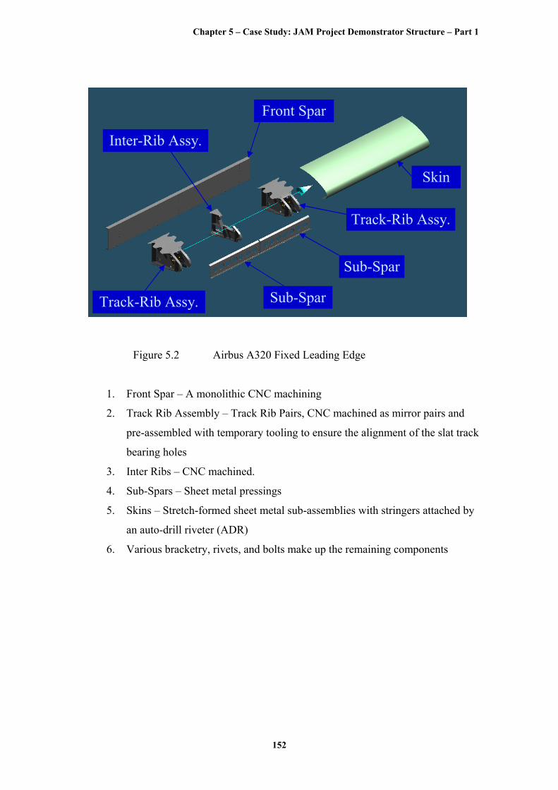
Referring to Figure 5.2, the principal components of the JAM Demonstrator
Structure are:-
Fixed Leading Edge
Demonstrator Section
Chapter 5 – Case Study: JAM Project Demonstrator Structure – Part 1
152
Skin
Front Spar
Inter-Rib Assy.
Track-Rib Assy. Sub-Spar
Sub-Spar
Track-Rib Assy.
Figure 5.2 Airbus A320 Fixed Leading Edge
1. Front Spar – A monolithic CNC machining
2. Track Rib Assembly – Track Rib Pairs, CNC machined as mirror pairs and
pre-assembled with temporary tooling to ensure the alignment of the slat track
bearing holes
3. Inter Ribs – CNC machined.
4. Sub-Spars – Sheet metal pressings
5. Skins – Stretch-formed sheet metal sub-assemblies with stringers attached by
an auto-drill riveter (ADR)
6. Various bracketry, rivets, and bolts make up the remaining components
Chapter 5 – Case Study: JAM Project Demonstrator Structure – Part 1
153
5.2.1 Re-engineering Ground Rules
The following three ground rules were laid down for the re-engineering of the
Fixed Leading Edge:
1. Minimal quantity of ‘Product Specific Tooling’
2. No re-design that would require re-certification of the structure
3. No increase in overall weight of the structure
The first ground rule, ‘Minimal quantity of ‘Product Specific Tooling’’, was
clearly the goal of the re-engineering exercise.
However, this had to be achieved with the caveat that any re-engineered structure
and assembly would have to be feasible within the next three years of the completion of
the JAM project. This meant that no major re-design was possible, as this would entail
large changes to the structure making it necessary to be re-certified by the Civil
Aviation Authorities, which is extremely expensive.
Finally, no increase in the overall weight of the structure was allowed, as any
extra weight would impede the product’s guaranteed performance. Hence, any
additional weight had to be negated by reducing the weight in other areas.
5.3 Results of the Application of AIM-FOR-JAM
In the course of the JAM Project, the AIM-FOR-JAM methodology was
developed, as described in Chapter 3, and AIM-FOR-JAM was applied to the JAM
Demonstrator Structure. The development of the AIM-FOR-JAM methodology was
organic so the re-engineering of the JAM Demonstrator Structure did not follow exactly
the logical course as proposed in the AIM-FORJAM methodology. Nevertheless, a
summary of the results is presented according to the sequence of the AIM-FOR-JAM
methodology illustrated in Figure 3.12.
Chapter 5 – Case Study: JAM Project Demonstrator Structure – Part 1
154
5.3.1 Accreditation of the Specific Work Completed on the
JAM Project Demonstrator Structure
The following sections describe the results of the application of the AIM-FOR-
JAM methodology to the JAM Project Demonstrator Structure. Referring to Figure 3.1,
each of the four, main areas of research focus identified at the beginning of the research
activity was assigned to individual members of the JAM Project research team at
Cranfield, as follows:
• The Manufacturing Process Capabilities research was undertaken by Graham
Burley
• The Error Budgeting research was undertaken by Randolph Odi
• The Costings Analysis and Feature Library for Jigless Assembly research was
undertaken by the author and is the particular focus of this thesis
The design for jigless assembly of the JAM Project Demonstrator Structure,
achieved as a result of applying the AIM-FOR-JAM methodology, was brought about
by the efforts of a joint design team made-up of the individual members of the JAM
Project research team listed above, along with support from other associates from
academia and industry.
5.3.2 Key Characteristics
The JAM Demonstrator Structure Key Characteristics were identified through a
process of background reading, interviewing the appropriate BAE SYSTEMS’ Cell
Managers, Airbus designers, tooling experts and through discussion with the other
university research teams. In addition, a number of fact-finding visits were made to the
Airbus A320 Fixed Leading Edge assembly cells at Samlesbury, to the A340 Fixed
Leading Edge assembly cell at Filton and to the final Wing Assembly cells at
Broughton, Chester.

Chapter 5 – Case Study: JAM Project Demonstrator Structure – Part 1
155
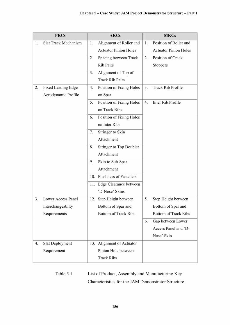
The list of identified Product, Assembly and Manufacturing Key Characteristics
are portrayed in the following Table 5.1.
It should be noted that the Product Key Characteristics would remain constant for
the same product as long as its design is not altered; the Assembly and Manufacturing
Key Characteristics will change for different Assembly and Manufacturing strategies.
Chapter 5 – Case Study: JAM Project Demonstrator Structure – Part 1
156
PKCs AKCs MKCs
1. Alignment of Roller and
Actuator Pinion Holes
1. Position of Roller and
Actuator Pinion Holes
2. Spacing between Track
Rib Pairs
1. Slat Track Mechanism
3. Alignment of Top of
Track Rib Pairs
2. Position of Crack
Stoppers
4. Position of Fixing Holes
on Spar
3. Track Rib Profile
5. Position of Fixing Holes
on Track Ribs
6. Position of Fixing Holes
on Inter Ribs
7. Stringer to Skin
Attachment
8. Stringer to Top Doubler
Attachment
9. Skin to Sub-Spar
Attachment
10. Flushness of Fasteners
2. Fixed Leading Edge
Aerodynamic Profile
11. Edge Clearance between
‘D-Nose’ Skins
4. Inter Rib Profile
5. Step Height between
Bottom of Spar and
Bottom of Track Ribs
3. Lower Access Panel
Interchangeabilty
Requirements
12. Step Height between
Bottom of Spar and
Bottom of Track Ribs
6. Gap between Lower
Access Panel and ‘D-
Nose’ Skin
4. Slat Deployment
Requirement
13. Alignment of Actuator
Pinion Hole between
Track Ribs
Table 5.1 List of Product, Assembly and Manufacturing Key
Characteristics for the JAM Demonstrator Structure
Chapter 5 – Case Study: JAM Project Demonstrator Structure – Part 1
157
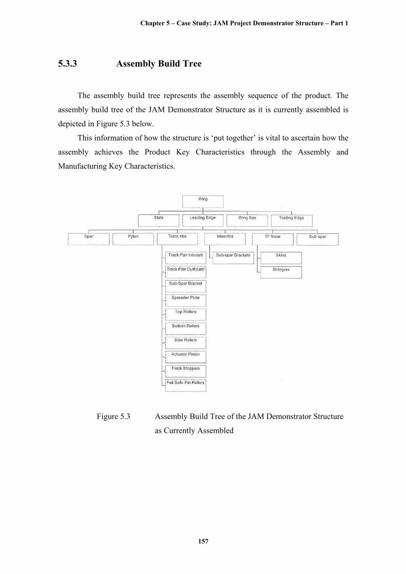
5.3.3 Assembly Build Tree
The assembly build tree represents the assembly sequence of the product. The
assembly build tree of the JAM Demonstrator Structure as it is currently assembled is
depicted in Figure 5.3 below.
This information of how the structure is ‘put together’ is vital to ascertain how the
assembly achieves the Product Key Characteristics through the Assembly and
Manufacturing Key Characteristics.
Figure 5.3 Assembly Build Tree of the JAM Demonstrator Structure
as Currently Assembled
Chapter 5 – Case Study: JAM Project Demonstrator Structure – Part 1
158
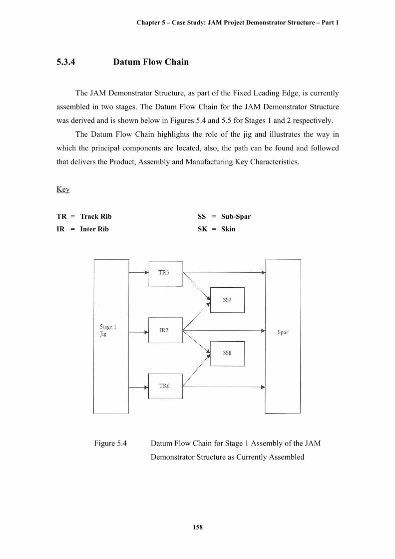
5.3.4 Datum Flow Chain
The JAM Demonstrator Structure, as part of the Fixed Leading Edge, is currently
assembled in two stages. The Datum Flow Chain for the JAM Demonstrator Structure
was derived and is shown below in Figures 5.4 and 5.5 for Stages 1 and 2 respectively.
The Datum Flow Chain highlights the role of the jig and illustrates the way in
which the principal components are located, also, the path can be found and followed
that delivers the Product, Assembly and Manufacturing Key Characteristics.
Key
TR = Track Rib SS = Sub-Spar
IR = Inter Rib SK = Skin
Figure 5.4 Datum Flow Chain for Stage 1 Assembly of the JAM
Demonstrator Structure as Currently Assembled
Chapter 5 – Case Study: JAM Project Demonstrator Structure – Part 1
159
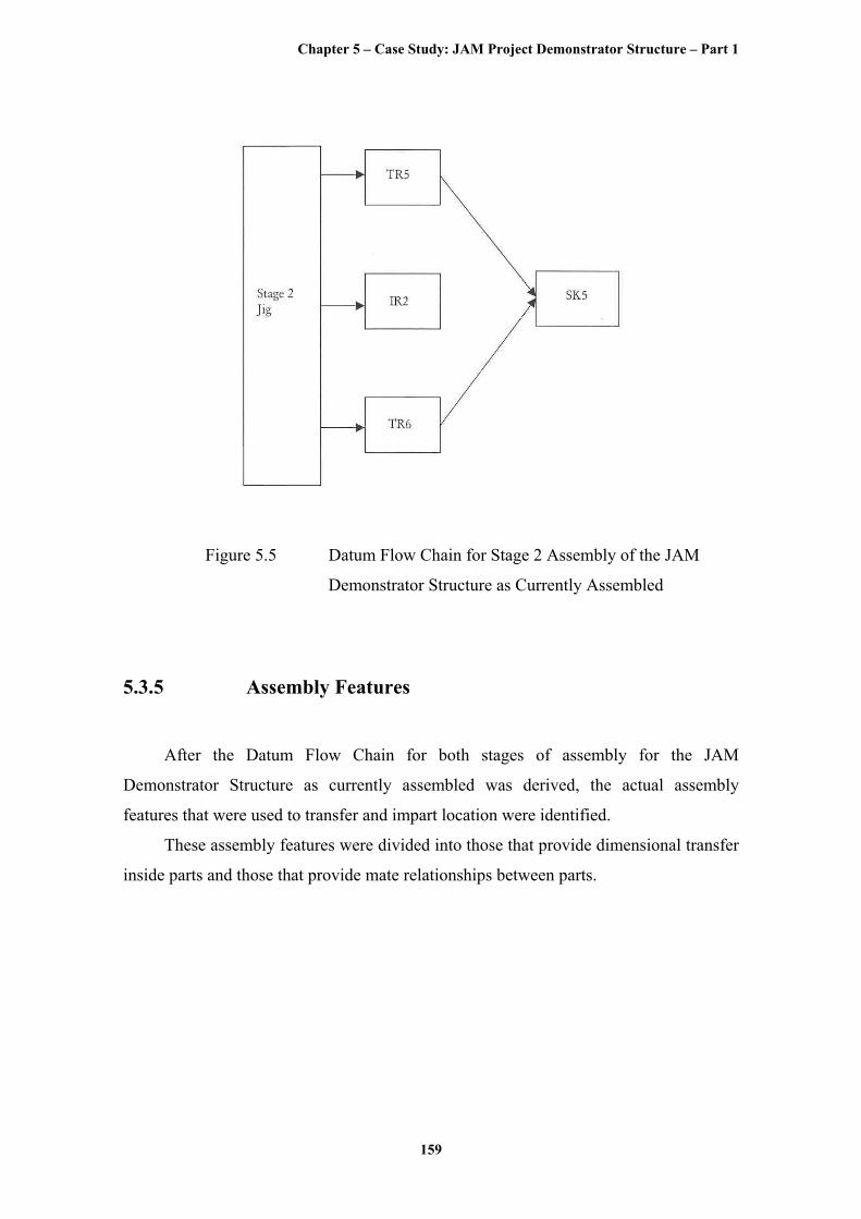
Figure 5.5 Datum Flow Chain for Stage 2 Assembly of the JAM
Demonstrator Structure as Currently Assembled
5.3.5 Assembly Features
After the Datum Flow Chain for both stages of assembly for the JAM
Demonstrator Structure as currently assembled was derived, the actual assembly
features that were used to transfer and impart location were identified.
These assembly features were divided into those that provide dimensional transfer
inside parts and those that provide mate relationships between parts.
Chapter 5 – Case Study: JAM Project Demonstrator Structure – Part 1
160
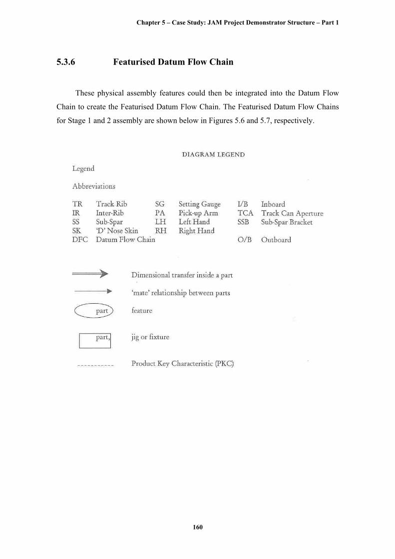
5.3.6 Featurised Datum Flow Chain
These physical assembly features could then be integrated into the Datum Flow
Chain to create the Featurised Datum Flow Chain. The Featurised Datum Flow Chains
for Stage 1 and 2 assembly are shown below in Figures 5.6 and 5.7, respectively.
Chapter 5 – Case Study: JAM Project Demonstrator Structure – Part 1
161
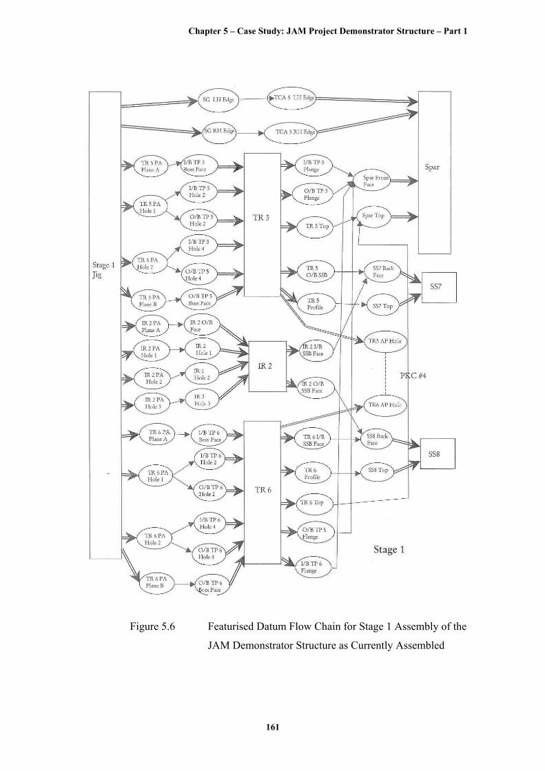
Figure 5.6 Featurised Datum Flow Chain for Stage 1 Assembly of the
JAM Demonstrator Structure as Currently Assembled

Chapter 5 – Case Study: JAM Project Demonstrator Structure – Part 1
162
Figure 5.7 Featurised Datum Flow Chain for Stage 2 Assembly of the
JAM Demonstrator Structure as Currently Assembled

Chapter 5 – Case Study: JAM Project Demonstrator Structure – Part 1
163
5.3.7 Alternative Assembly Concepts
Once the current assembly of the JAM Demonstrator Structure had been analysed
using the tools described in the preceding sections, Alternative Assembly Concepts were
conceived as a result of several brainstorming sessions.
These were :-
1. Building from the Skin inwards – Envelope Tooling
2. Building on to the Spar
3. Building on the Track Rib Hinge Line
4. Using the Bleed Air Duct as ‘Flyaway Tooling’
5. Using Re-configurable Modular Tooling
6. Building with Modular Sub-Assemblies
7. Building on to the Wing Box
Options 4 to 7 would require substantial redesign and therefore violates rule 2 of
the Re-engineering Ground Rules, ‘No re-design that would require re-certification of
the structure’. However, these options may be a possibility for future redesign research
activities rather than the immediate re-engineering research activities that are the focus
of this work.
5.3.8 Error Budgets for Alternative Assembly Concepts
Error Budgets were calculated for options 1 to 3 of the Alternative Assembly
Concepts. Featurised Datum Flow Chains were created using a potential set of initial,
preliminary assembly features.
The results of the Error Budgets for the three Alternative Assembly Concepts are
shown in Table 5.2, below, all values are in mm’s.
Chapter 5 – Case Study: JAM Project Demonstrator Structure – Part 1
164
Table 5.2 Error Budgets for Alternative Assembly Concepts
These values can be compared with the values obtained for the Error Budget of
the JAM Demonstrator Structure as currently assembled, as shown in Table 5.3, below,
all values are in mm’s.
Table 5.3 Error Budget for JAM Demonstrator Structure as
Currently Assembled
5.3.9 Assembly Concept Selection
It can be seen from Tables 5.2 and 5.3 that the Total System Error of Concept 1 is
almost as large as that for the JAM Demonstrator Structure as currently assembled, i.e.
19.12 mm for Concept 1 compared to 22.18 mm for the JAM Demonstrator Structure as
currently assembled. Therefore, Concept 1 would not appear to be much of an
improvement from the current assembly.
Chapter 5 – Case Study: JAM Project Demonstrator Structure – Part 1
165
Concept 2 and Concept 3 are both significant improvements on the JAM
Demonstrator Structure as currently assembled, in terms of Total System Error. Concept
2 has a Total System Error of 8.07 mm and Concept 3 has a Total System Error of 7.92
mm.
Both concepts also have similar Total Transfer Errors – Concept 2 with 7.30 mm
and Concept 3 with 7.73 mm – the Total Transfer Error being the error in dimensional
transfer within a part.
The Total Mate Error, the error in the mate relationships between parts, is 1.72
mm for Concept 3. However, the Total Mate Error of Concept 2 is 3.43 mm, nearly
double that of Concept 2.
On this result, Concept 3 would appear to be the better option. On the other hand,
the design of Concept 3 involves the use of precise Spacer Bars between Track Rib
Pairs and Inter Ribs – in addition to the Dummy Rollers that are presently used to
maintain the distance between each Track Rib of the Track Rib Pair. The Spacer Bars
would then connect to the Dummy Rollers and the Track and Inter Ribs could be pre-
assembled as a sub-assembly, thereby reducing the amount and complexity of jigs
required.
With this further explanation, Concept 3 would necessitate more redesign than at
first appears. Minor design modifications to the Inter Ribs are necessary to allow the
Spacer Bars to be connected through them. Also, the Spacer Bars would be product-
specific, as they would have to be a particular length for the product in question.
For these reasons, Concept 2 was finally selected as the Alternative Assembly
Concept, even though it has a larger Total Mate Error than Concept 3. Concept 2 is, in
fact, somewhat simpler than Concept 3 and is less product-specific.
5.4 Alternative Assembly Concept 2 – Building on to
the Spar
This section will describe the assembly of the re-engineered JAM Demonstrator
Structure using Alternative Assembly Concept 2 – Building on to the Spar.
Chapter 5 – Case Study: JAM Project Demonstrator Structure – Part 1
166
A short description and figure for each stage of the assembly of the re-engineered
JAM Demonstrator Structure has been included. Moreover, a review of how the
Assembly Feature Selection process was applied to enable Jigless Assembly as part of
the AIM-FOR-JAM methodology is given for each stage of the assembly.
However, due to the ground rules of the re-engineering, as stated in section 5.2.1,
major re-design was not possible and hence, the scope of assembly features available for
selection was limited. In fact, the principal type of Location Feature Pairs that were
selected was ‘Hole-to-Hole’ Location Features, described in the following sections,
because these types of Location Features are very common in aerospace assembly and
are well understood.
For a more adventurous design with fewer restrictions it would have been possible
to select more ‘unconventional’ Location Features.
Even so, the Assembly Feature Selection process is still valid and the results of its
application presented below serve to illustrate that the process is capable of catering for
both conventional type Location Features, such as holes, and unconventional type
Location Features, such as Optical Targets.
5.4.1 Assembly Stage 1: Build Tool to Spar Assembly
5.4.1.1 Description of the Build Tool
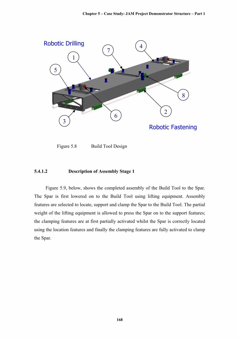
Figure 5.8, below, shows the design of the ‘Build Tool’. As the Spar is a long,
flexible, monolithic CNC machined component, simple stiffness calculations indicated
that it would need to be supported during the build cycle. A Build Tool was therefore
designed to support and locate the Spar and to enable a semi-automated build sequence
using two, rail-mounted, multi-axis CNC machining and fastening heads – one
operating above and the other below the Spar. A risk analysis that was undertaken
suggested that the drilling heads should be fitted with machine vision devices to locate
the assembly features, as the Spar growth following shot peening and an increase in
ambient temperature of 5°C was reported to be as much as 2.0mm and 1.7mm,
respectively.
Chapter 5 – Case Study: JAM Project Demonstrator Structure – Part 1
167
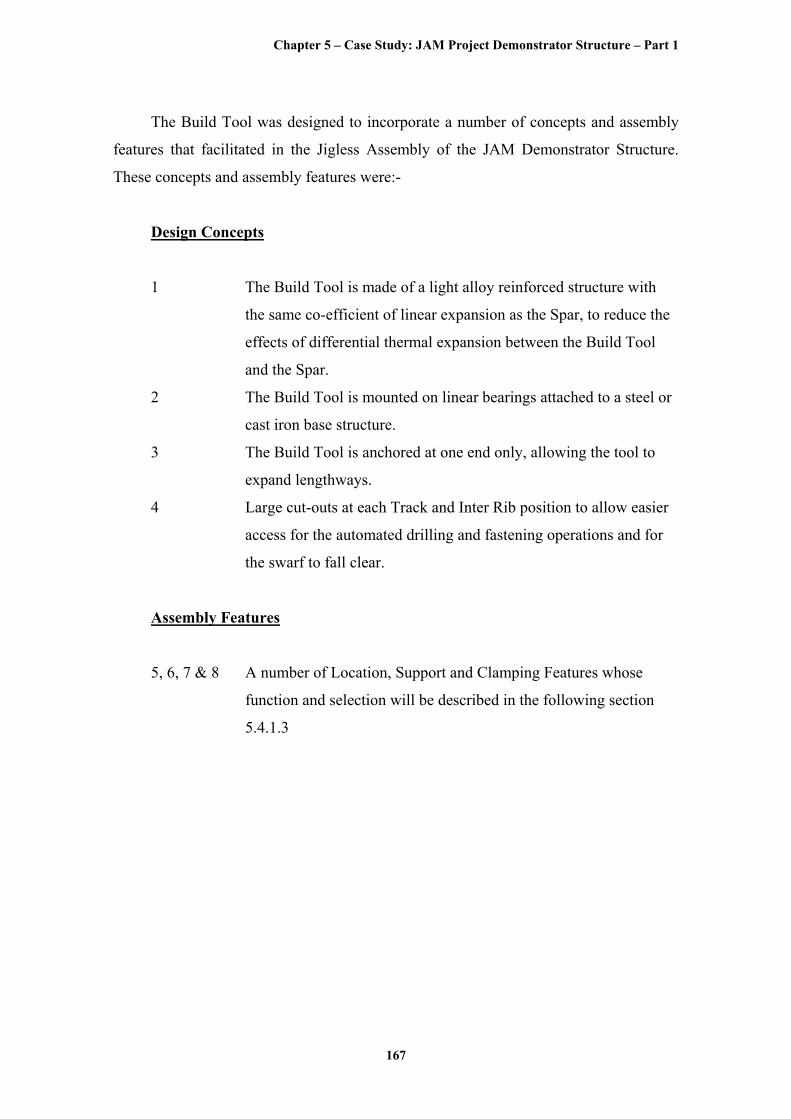
The Build Tool was designed to incorporate a number of concepts and assembly
features that facilitated in the Jigless Assembly of the JAM Demonstrator Structure.
These concepts and assembly features were:-
Design Concepts
1 The Build Tool is made of a light alloy reinforced structure with
the same co-efficient of linear expansion as the Spar, to reduce the
effects of differential thermal expansion between the Build Tool
and the Spar.
2 The Build Tool is mounted on linear bearings attached to a steel or
cast iron base structure.
3 The Build Tool is anchored at one end only, allowing the tool to
expand lengthways.
4 Large cut-outs at each Track and Inter Rib position to allow easier
access for the automated drilling and fastening operations and for
the swarf to fall clear.
Assembly Features
5, 6, 7 & 8 A number of Location, Support and Clamping Features whose
function and selection will be described in the following section
5.4.1.3
Chapter 5 – Case Study: JAM Project Demonstrator Structure – Part 1
168
1
3
5
6
7
2
4
1
8
Robotic Drilling
Robotic Fastening
Figure 5.8 Build Tool Design
5.4.1.2 Description of Assembly Stage 1
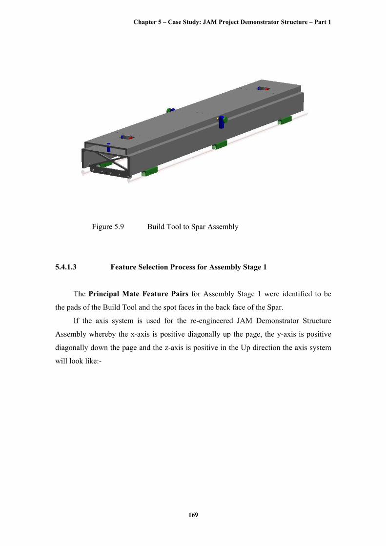
Figure 5.9, below, shows the completed assembly of the Build Tool to the Spar.
The Spar is first lowered on to the Build Tool using lifting equipment. Assembly
features are selected to locate, support and clamp the Spar to the Build Tool. The partial
weight of the lifting equipment is allowed to press the Spar on to the support features;
the clamping features are at first partially activated whilst the Spar is correctly located
using the location features and finally the clamping features are fully activated to clamp
the Spar.
Chapter 5 – Case Study: JAM Project Demonstrator Structure – Part 1
169
Figure 5.9 Build Tool to Spar Assembly
5.4.1.3 Feature Selection Process for Assembly Stage 1
The Principal Mate Feature Pairs for Assembly Stage 1 were identified to be
the pads of the Build Tool and the spot faces in the back face of the Spar.
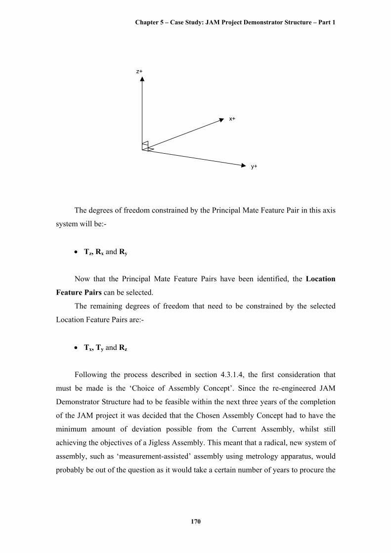
If the axis system is used for the re-engineered JAM Demonstrator Structure
Assembly whereby the x-axis is positive diagonally up the page, the y-axis is positive
diagonally down the page and the z-axis is positive in the Up direction the axis system
will look like:-
Chapter 5 – Case Study: JAM Project Demonstrator Structure – Part 1
170
x+
y+
z+
The degrees of freedom constrained by the Principal Mate Feature Pair in this axis
system will be:-
• Tz, Rx and Ry
Now that the Principal Mate Feature Pairs have been identified, the Location
Feature Pairs can be selected.
The remaining degrees of freedom that need to be constrained by the selected
Location Feature Pairs are:-
• Tx, Ty and Rz
Following the process described in section 4.3.1.4, the first consideration that
must be made is the ‘Choice of Assembly Concept’. Since the re-engineered JAM
Demonstrator Structure had to be feasible within the next three years of the completion
of the JAM project it was decided that the Chosen Assembly Concept had to have the
minimum amount of deviation possible from the Current Assembly, whilst still
achieving the objectives of a Jigless Assembly. This meant that a radical, new system of
assembly, such as ‘measurement-assisted’ assembly using metrology apparatus, would
probably be out of the question as it would take a certain number of years to procure the
Chapter 5 – Case Study: JAM Project Demonstrator Structure – Part 1
171
new system, become familiarised and industrialise the system and then train the
operators in how to use it.
Hence, the Assembly Concept chosen relied on the parts themselves to provide the
correct location between each other, which is normally the function of the jig. This
narrowed the selection of the location features to hard, part-integrated type location
features.
Once this choice had been made, the selection of the Location Feature Pairs could
commence. As asserted in section 4.3.1.4.2, the best Location Feature Pairs from an
assembly perspective are those that constrain the most degrees of freedom. In this
particular case, then, the best Location Feature Pair should constrain the remaining
degrees of freedom in Tx, Ty and Rz.
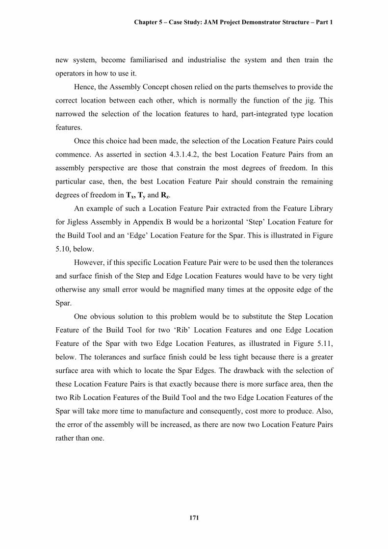
An example of such a Location Feature Pair extracted from the Feature Library
for Jigless Assembly in Appendix B would be a horizontal ‘Step’ Location Feature for
the Build Tool and an ‘Edge’ Location Feature for the Spar. This is illustrated in Figure
5.10, below.
However, if this specific Location Feature Pair were to be used then the tolerances
and surface finish of the Step and Edge Location Features would have to be very tight
otherwise any small error would be magnified many times at the opposite edge of the
Spar.
One obvious solution to this problem would be to substitute the Step Location
Feature of the Build Tool for two ‘Rib’ Location Features and one Edge Location
Feature of the Spar with two Edge Location Features, as illustrated in Figure 5.11,
below. The tolerances and surface finish could be less tight because there is a greater
surface area with which to locate the Spar Edges. The drawback with the selection of
these Location Feature Pairs is that exactly because there is more surface area, then the
two Rib Location Features of the Build Tool and the two Edge Location Features of the
Spar will take more time to manufacture and consequently, cost more to produce. Also,
the error of the assembly will be increased, as there are now two Location Feature Pairs
rather than one.
Chapter 5 – Case Study: JAM Project Demonstrator Structure – Part 1
172
‘Step’ Location Feature of the Build Tool
‘Edge’ Location Feature of the Spar
Figure 5.10 Illustration of a horizontal ‘Step’ Location Feature for the
Build Tool and an ‘Edge’ Location Feature for the Spar
1st ‘Rib’ Location Feature of the Build Tool
1st ‘Edge’ Location Feature
of the Spar
2nd ‘Rib’ Location Feature of the Build Tool
2nd ‘Edge’ Location Feature
of the Spar
Figure 5.11 Illustration of two ‘Rib’ Location Features for the Build
Tool and two ‘Edge’ Location Features for the Spar
Chapter 5 – Case Study: JAM Project Demonstrator Structure – Part 1
173
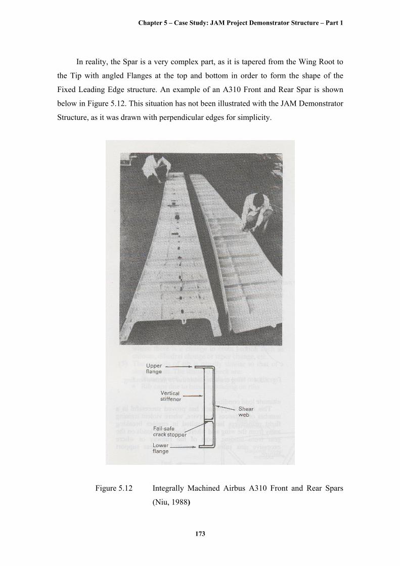
In reality, the Spar is a very complex part, as it is tapered from the Wing Root to
the Tip with angled Flanges at the top and bottom in order to form the shape of the
Fixed Leading Edge structure. An example of an A310 Front and Rear Spar is shown
below in Figure 5.12. This situation has not been illustrated with the JAM Demonstrator
Structure, as it was drawn with perpendicular edges for simplicity.
Figure 5.12 Integrally Machined Airbus A310 Front and Rear Spars
(Niu, 1988)
Chapter 5 – Case Study: JAM Project Demonstrator Structure – Part 1
174
Therefore, any Location Features that use the Edge of the Spar as a Location
Feature are at an inherent disadvantage because the Location Features mating with the
Edge Location Feature of the Spar would have to be different and unique at all points
along the length of the Spar. This would make the design and manufacture of the Build
Tool very expensive and time-consuming.
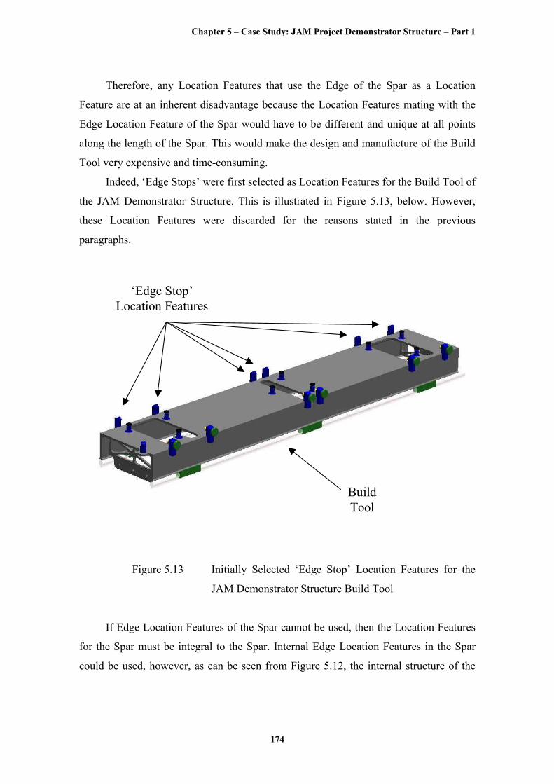
Indeed, ‘Edge Stops’ were first selected as Location Features for the Build Tool of
the JAM Demonstrator Structure. This is illustrated in Figure 5.13, below. However,
these Location Features were discarded for the reasons stated in the previous
paragraphs.
‘Edge Stop’ Location Features
Build Tool
Figure 5.13 Initially Selected ‘Edge Stop’ Location Features for the
JAM Demonstrator Structure Build Tool
If Edge Location Features of the Spar cannot be used, then the Location Features
for the Spar must be integral to the Spar. Internal Edge Location Features in the Spar
could be used, however, as can be seen from Figure 5.12, the internal structure of the
Chapter 5 – Case Study: JAM Project Demonstrator Structure – Part 1
175
Spar is very intricate so finding a simple and reproducible Internal Edge Location
Feature is difficult.
With this observation, it is evident that it is not easy to select a Location Feature
that constrains all three of the remaining degrees of freedom, especially since the Spar is
so long and flexible.
Hence, a Location Feature Pair is required to constrain at least two of the
remaining degrees of freedom and then one or more other Location Feature Pairs can be
selected to constrain the last degree of freedom. The Location Feature Pairs could be
placed at opposite ends of the Spar to try to counteract some of the complications
caused by its length and flexibility.
Since it has been shown that any type of Internal Edge Location Feature would be
problematic, the most simple and recognisable type of Location Feature that could be
employed to constrain two degrees of freedom would be a ‘Hole’ through the Spar. The
‘hole’, as already stated, is one of the most commonly used types of Location Features
in assembly.
The design issues of holes are relatively well understood and thoroughly
researched. Appendix A, ‘Effect of Assembly Features on Structures - FE Modelling’,
demonstrates that for a group of Location Features, the hole is one of the least stress
raising compared to other types of Location Features, such as the ‘Boss’ or the ‘Cone’.
Manufacturing of holes is also greatly practiced, particularly in aerospace
assembly where generally, thousands of bolts and rivets are fitted through holes to
fasten aerostructures. As illustrated by Figure 4.13, drilling is not the most accurate of
manufacturing process but it can be made more accurate by further reaming. Hence, the
drilling of holes is able to strike a balance between the tolerance achievable and the
relative cost of the process. Figure 4.15 shows that drilling of holes does not produce a
remarkably good surface finish but this is not normally a problem when fitting
interference bolts or rivets, as is typically the case.
Holes have been used from the very beginning of aerospace manufacture and
assembly, and for that matter in all forms of assembly, subsequently the cost of
designing and manufacturing holes is very well appreciated and can be worked out
easily.
Chapter 5 – Case Study: JAM Project Demonstrator Structure – Part 1
176
In addition, a common practice in aerospace assembly is to first clamp a part and
then drill a hole in it to be used as the datum for the part in subsequent machining and
assembly stages (provided it is not cut off in the process). If the hole is also used as the
first Location Feature, then there will be no Transfer Error for this Location Feature Pair
as the Datum and the Location Feature are one and the same. This will reduce the error
in the assembly greatly due to the fact that the Transfer Error makes up most of the
System Error in an assembly, as illustrated in Tables 5.2 and 5.3.
At this point, a note of caution must be provided in that even given all of the
above advantages, alternatives to the hole as a Location Feature should be considered.
There are two main reasons for this.
The first reason being that, although holes are less stress raising then other
Location Features, such as Bosses or Cones, the stress between holes is a major concern
since if a crack develops at a hole due to fatigue, for example, it will spread to the
surrounding holes, and if adequate distance has not been left between the holes then the
part may fail.
The second reason for considering other types of Location Features instead of
holes is that, while it may not be expensive to produce one or even a few holes given the
large number of holes that are usually produced for typical aircraft, the cost quickly
increases to a significant proportion of the total assembly cost. For this reason, more and
more research and development is being applied to other forms of assembly in
aerospace. These other forms include net-shape manufacturing by casting or forming
methods, unitised structures by design or various forms of welding such as laser- or stir-
welding (Kalpakjian, 1995). These other forms of assembly tend to be more flexible and
less product-specific as the drilling of holes and fastening of bolts and rivets is either
very labour-intensive or if automated, the machines are product-specific and expensive,
depending on the scale of operation.
Nevertheless, the Hole has been selected as the first Location Feature for the Spar.
The Spar, itself, already contains a number of pre-drilled holes, which in theory
could be used for the Hole Location Features. The JAM Demonstrator Structure has two
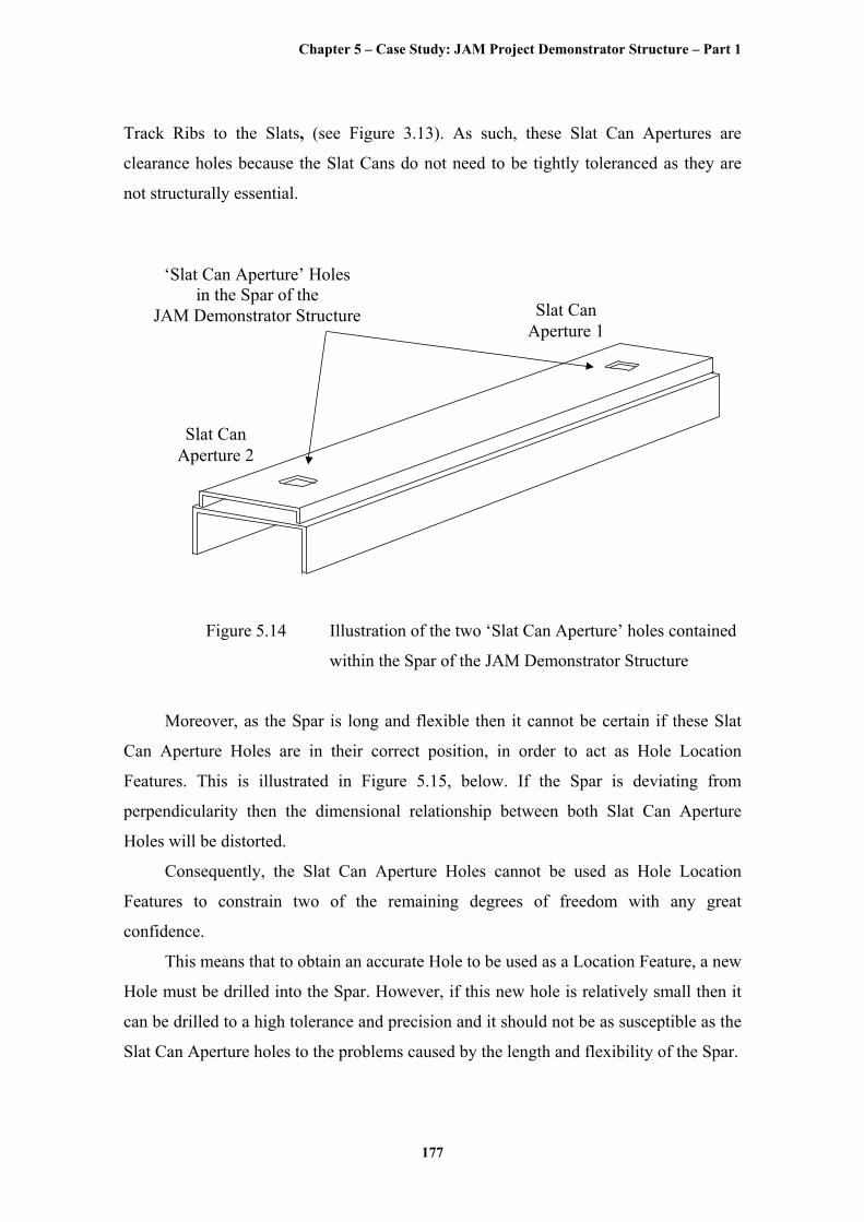
of these holes at either end of the Spar. This is illustrated in Figure 5.14, below.
These holes are known as ‘Slat Can Apertures’ because they are the apertures
through which the ‘Slat Cans’ are attached that house the ‘Slat Tracks’ connecting the
Chapter 5 – Case Study: JAM Project Demonstrator Structure – Part 1
177
Track Ribs to the Slats, (see Figure 3.13). As such, these Slat Can Apertures are
clearance holes because the Slat Cans do not need to be tightly toleranced as they are
not structurally essential.
‘Slat Can Aperture’ Holes in the Spar of the
JAM Demonstrator Structure
Slat Can Aperture 2
Slat Can Aperture 1
Figure 5.14 Illustration of the two ‘Slat Can Aperture’ holes contained
within the Spar of the JAM Demonstrator Structure
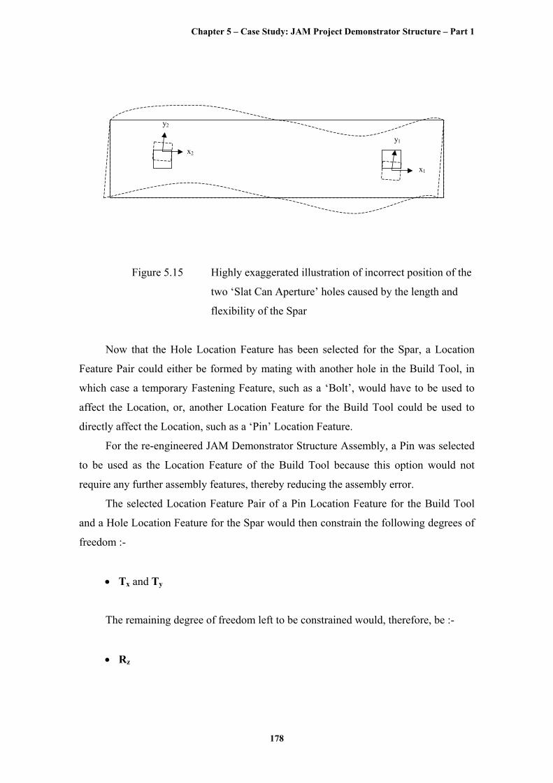
Moreover, as the Spar is long and flexible then it cannot be certain if these Slat
Can Aperture Holes are in their correct position, in order to act as Hole Location
Features. This is illustrated in Figure 5.15, below. If the Spar is deviating from
perpendicularity then the dimensional relationship between both Slat Can Aperture
Holes will be distorted.
Consequently, the Slat Can Aperture Holes cannot be used as Hole Location
Features to constrain two of the remaining degrees of freedom with any great
confidence.
This means that to obtain an accurate Hole to be used as a Location Feature, a new
Hole must be drilled into the Spar. However, if this new hole is relatively small then it
can be drilled to a high tolerance and precision and it should not be as susceptible as the
Slat Can Aperture holes to the problems caused by the length and flexibility of the Spar.
Chapter 5 – Case Study: JAM Project Demonstrator Structure – Part 1
178
y1
x1
y2
x2
Figure 5.15 Highly exaggerated illustration of incorrect position of the
two ‘Slat Can Aperture’ holes caused by the length and
flexibility of the Spar
Now that the Hole Location Feature has been selected for the Spar, a Location
Feature Pair could either be formed by mating with another hole in the Build Tool, in
which case a temporary Fastening Feature, such as a ‘Bolt’, would have to be used to
affect the Location, or, another Location Feature for the Build Tool could be used to
directly affect the Location, such as a ‘Pin’ Location Feature.
For the re-engineered JAM Demonstrator Structure Assembly, a Pin was selected
to be used as the Location Feature of the Build Tool because this option would not
require any further assembly features, thereby reducing the assembly error.
The selected Location Feature Pair of a Pin Location Feature for the Build Tool
and a Hole Location Feature for the Spar would then constrain the following degrees of
freedom :-
• Tx and Ty
The remaining degree of freedom left to be constrained would, therefore, be :-
• Rz
Chapter 5 – Case Study: JAM Project Demonstrator Structure – Part 1
179
If the Spar was perfectly rigid, as would be assumed for kinematic purposes, then
the first Slat Can Aperture Hole could be used to constrain the remaining degree of
freedom, Rz. In reality, the Spar is not rigid as was illustrated in Figure 5.15. To cope
with the problems of flexibility and distortion, the Spar is located via both Slat Can
Aperture Holes. Technically, this would mean that the Spar was now over-constrained
as the remaining degree of freedom is being constrained by more than one Location
Feature. However, this situation is not applicable as ‘Semi-Kinematic’ Principles are
being used because of the flexibility and distortion of the Spar.
The location of the Spar at the two Track Rib positions is affected by two
automated centring devices, consisting of one Fixed Pin and one hydraulically operated,
Expanding Pin. The Fixed Pin locates the Top Edge of the Slat Can Aperture Holes,
which is referenced to the centreline of the Spar, and the Expanding Pin locates the
Bottom Edge of the Slat Can Aperture Holes, whose position may be unknown due to
the Spar’s flexibility and distortion. This is shown in Figure 5.8, where the Fixed Pins
are represented by the Blue Pins within the Slat Can Aperture Holes and the Expanding
Pins are represented by the Red Pins within the Slat Can Aperture Holes.
The Top Edge, rather than the Bottom Edge, of the Slat Can Aperture Holes was
selected to be located by the Fixed Pin because the dimensional relationships of the Top
of the Spar and the Top of the Track Ribs are critical to achieving some of the Product
Key Characteristics listed in Table 5.1. Although this would also mean that the Top
Edge of the Slat Can Aperture Holes would need to be more tightly toleranced than the
Bottom Edge, resulting in a minor design modification to the current JAM Project
Demonstrator Structure.
The Spar is now located on the Build Tool, with all of the degrees of freedom
constrained. The location of the Spar at both Track Ribs has been realised by the two
automated centring devices. All that remains is for the Spar to be correctly located at the
Inter Rib. Here, the same difficulties arise as for the Track Ribs because of the Spar’s
flexibility and distortion. If the Spar was perfectly rigid then it should be correctly
located at the Inter Rib. However, since it is not then some method of adjusting the Spar
at assembly is required to make sure that the Spar is, in fact, correctly located at the
Inter Rib.
Chapter 5 – Case Study: JAM Project Demonstrator Structure – Part 1
180
Automated Centring Devices would have been used for the Inter Rib as per the
Track Ribs but there is no Slat Can Aperture Hole at the Inter Rib, as the Slat Tracks are
only attached to the Track Ribs.
At this point, it needs to be highlighted that the correct location of, firstly, the
Spar in relation to both Track and Inter Ribs and, secondly, the Inter Rib in relation to
the Spar are two separate things. The correct location of the Spar in relation to both
Track and Inter Ribs is due to the Spar’s flexibility and distortion, which is independent
of the correct location of the Inter Rib in relation to the Spar. This means that the Inter
Rib can be correctly located in the x-axis on the Spar by being perpendicular to both
Track Ribs. Once this has been achieved, the Spar, itself, can be correctly located in the
y-axis.
The method that has been developed to accomplish the separate operations of both
correctly locating the Inter Rib to the Spar and also, the Spar to both Track and Inter
Ribs, is described in section 5.4.3 and 5.4.5, respectively.
After all of the Location Features have been selected, the remaining assembly
features need to be selected. The next of these are the Support Features.
As illustrated in Figure 5.4, the Pads of the Build Tool that acted as the Principal
Mate Feature Pairs with the Spot Faces in the back face of the Spar also serve as the
Support Features for the Spar. These Pads have been ‘Semi-Kinematically’ arranged, in
configurations of three to form a plane, to support the Spar. Ideally, there would only be
three pads to support the Spar but the Spar is too flexible to be only supported by three
pads, so the section between each Track and Inter Rib has been taken to be semi-rigid
with three Pads supporting each of these sections. The fact that these Support Pads are
raised also helps to reduce the risk of trapping swarf between the Spar and the Build
Tool.
The next assembly features to be selected were the Clamping Features. These
clamping features will hold the Spar firmly whilst any assembly operations are taking
place. The Pads of the Build Tool that are acting as Principal Mate Feature Pairs and
Support Features have, in addition, been fitted with flexible vacuum cups that ensure
that the Spar is pulled down and fully clamped for drilling and assembly.
Chapter 5 – Case Study: JAM Project Demonstrator Structure – Part 1
181
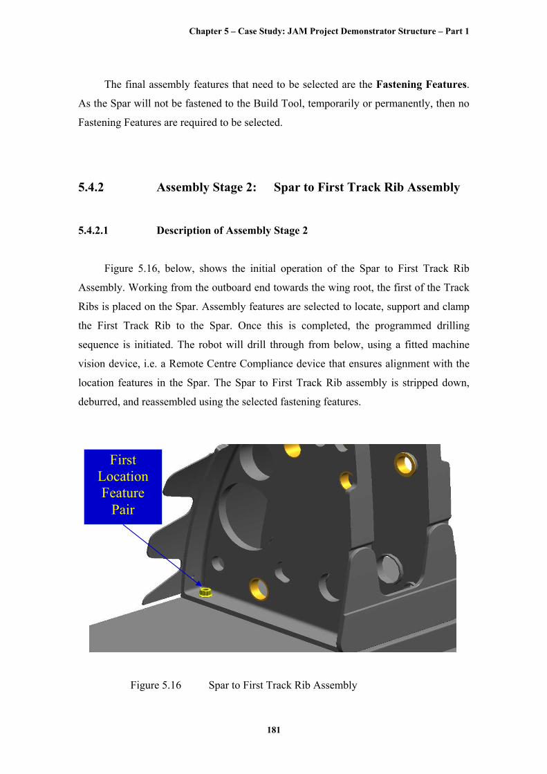
The final assembly features that need to be selected are the Fastening Features.
As the Spar will not be fastened to the Build Tool, temporarily or permanently, then no
Fastening Features are required to be selected.
5.4.2 Assembly Stage 2: Spar to First Track Rib Assembly
5.4.2.1 Description of Assembly Stage 2
Figure 5.16, below, shows the initial operation of the Spar to First Track Rib
Assembly. Working from the outboard end towards the wing root, the first of the Track
Ribs is placed on the Spar. Assembly features are selected to locate, support and clamp
the First Track Rib to the Spar. Once this is completed, the programmed drilling
sequence is initiated. The robot will drill through from below, using a fitted machine
vision device, i.e. a Remote Centre Compliance device that ensures alignment with the
location features in the Spar. The Spar to First Track Rib assembly is stripped down,
deburred, and reassembled using the selected fastening features.
First Location Feature
Pair
Figure 5.16 Spar to First Track Rib Assembly
Chapter 5 – Case Study: JAM Project Demonstrator Structure – Part 1
182
5.4.2.2 Feature Selection Process for Assembly Stage 2
The Principal Mate Feature Pairs for Assembly Stage 2 were identified to be
the front face of the Spar and the back face of the First Track Rib.
If the same axis system is used throughout the assembly of the re-engineered JAM
Demonstrator Structure Assembly, as described in section 5.4.2.2, then the degrees of
freedom constrained by the Principal Mate Feature Pair in this axis system will be:-
• Tz, Rx and Ry
As before, now that the Principal Mate Feature Pairs have been identified, the
Location Feature Pairs can be selected.
The remaining degrees of freedom that need to be constrained by the selected
Location Feature Pairs are:-
• Tx, Ty and Rz
The Location Feature Pair selection process for the Spar to First Track Rib
Assembly essentially followed the same arguments in the selection process as for the
Build Tool to Spar Assembly.
The correct location between parts was provided by the parts themselves using
hard, part-integrated type Location Features. Similar to the Build Tool, Step or Rib type
Location Features could have been selected to constrain the remaining degrees of
freedom between the Spar and the First Track Rib Assembly. Unlike the Spar, the Track
Rib would be less susceptible to the difficulties of having to produce a tight tolerance
and surface finish at inexpensive manufacturing costs because the Track Rib is a
relatively small and stiff component, which does not suffer the amount of flexibility and
distortion as the Spar. However, Appendix A, ‘Effect of Assembly Features on
Structures – FE Modelling’, concludes that any features added to the Spar will end up
acting as significant stress raisers, so the use of severe Location Features with abrupt
geometry, such as Steps or Ribs, is to be avoided.
Chapter 5 – Case Study: JAM Project Demonstrator Structure – Part 1
183
Hence, a Hole Location Feature was selected as the first Location Feature for the
Track Rib with the same justifications and caveats as described in the Build Tool to
Spar Assembly.
To form the Location Feature Pair for the Build Tool to Spar Assembly, a Pin was
selected as the first Location Feature for the Build Tool to mate with the Hole Location
Feature of the Spar. However, as stated in the preceding paragraph, any features added
to the Spar would act as significant stress raisers. As can be seen from Appendix A,
‘Effect of Assembly Features on Structures – FE Modelling’, a similar type Location
Feature, the External Cone, induces the highest stress in a group of assembly features.
This situation is acceptable for the Build Tool as it is not a flying component and the
stresses built-in by the Location Features are not so much of a concern. It is imperative,
though, for the Spar to be produced with as little built-in stress as possible to increase
service life and reduce fatigue. Consequently, a Hole Location Feature in the Spar was
selected in favour of a Pin Location Feature in order to minimise the built-in stresses.
This meant that a temporary Fastening Feature was required to affect the location.
This is dealt with at the end of the section.
The selected Location Feature Pair of a Hole Location Feature for the Spar and a
Hole Location Feature for the First Track Rib would then constrain the following
degrees of freedom :-
• Tx and Ty
The remaining degree of freedom left to be constrained would, therefore, be :-
• Rz
The Track Rib has been assumed to be stiff and small enough to be approximated
as a rigid component. Therefore, one or more other Location Feature can be selected to
constrain the final degree of freedom, as the Spar should at least be in the correct
location at the two track Rib positions due to the use of the automated centring devices.
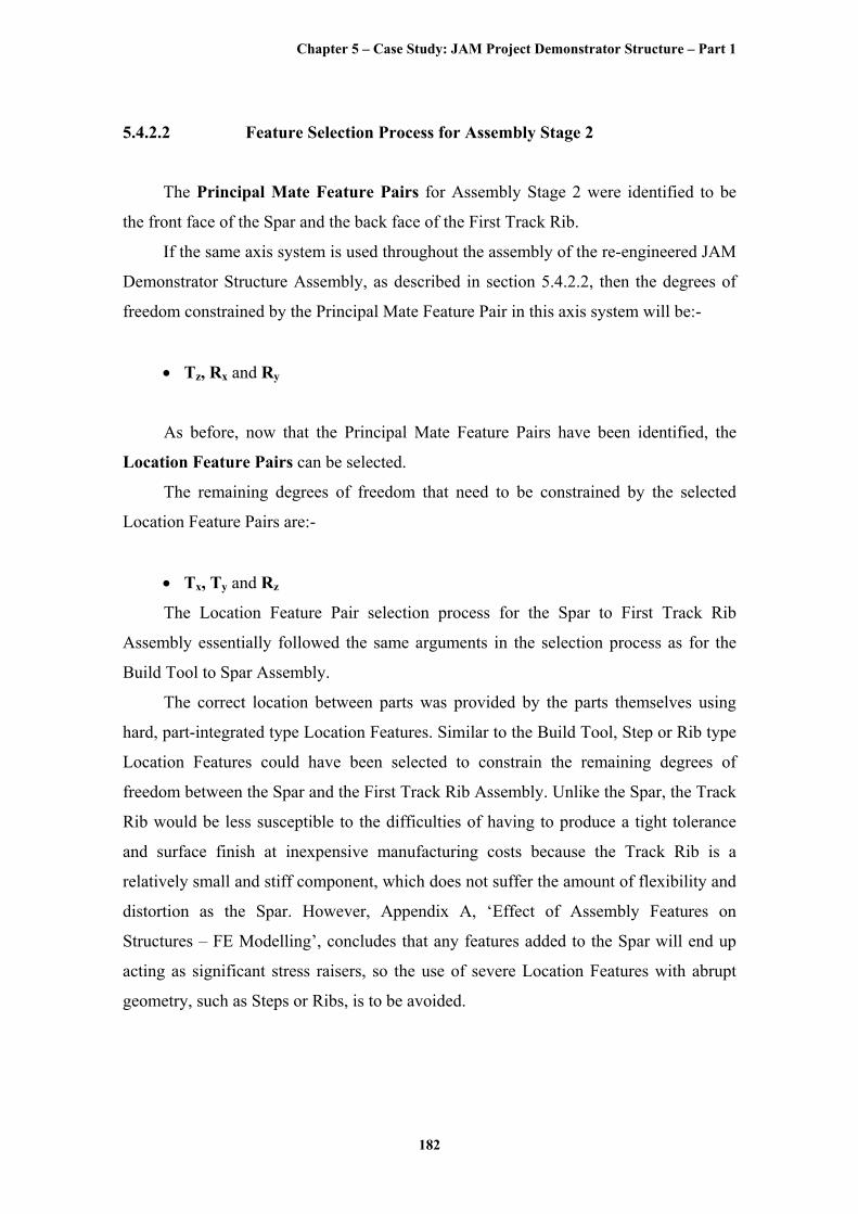
The Location Feature Pair selected to constrain the final degree of freedom is the
same as that for the first Location Feature Pair in order to keep a level of consistency,
Chapter 5 – Case Study: JAM Project Demonstrator Structure – Part 1
184
i.e. a Hole Location Feature for the First Track Rib and a Hole Location Feature for the
Spar. This is illustrated in Figure 5.17, below. The Second Location Feature Pair could
be placed anywhere around the First Track Rib and corresponding location of the Spar
and still constrain the final degree of freedom, Rz, though the ideal position of the
Second Location Feature Pair would be at the opposite corner of the First Track Rib and
its corresponding location of the Spar. This would provide the greatest distance between
both Location Feature Pairs and therefore, minimise the magnification of any possible
error caused by the tolerance of the First Location Feature Pair.
Selecting this particular Location Feature Pair, requires that the tolerancing of
both Location Feature Pairs must be very carefully worked out as the tolerances of the
First Location Feature Pair must be tight enough to constrain the First Track Rib in Tx
and Ty, and the tolerances of the Second Location Feature Pair must be tight enough to
constrain the First Track Rib in Rz but not to over-constrain any of the other already
constrained degrees of freedom. The Error Budgeting tool will aid in the early selection
of these critical tolerances and when the design and geometry are more developed, 3D
tolerancing analysis software can be used to refine the allocated tolerances.
Second Location Feature
Pair
Figure 5.17 Second Location Feature Pair
Chapter 5 – Case Study: JAM Project Demonstrator Structure – Part 1
185
The First Track Rib has now been correctly located to the Spar using Holes as
both Location Features for both of the Location Feature Pairs.
In common with the Build Tool to Spar Assembly, the Principal Mate Feature Pair
of the Spar to First Track Rib Assembly, identified as the front face of the Spar and the
back face of the First Track Rib, also serve as Support Features for the Spar and the
First Track Rib.
The temporary Fastening Features selected to affect the location of both Location
Feature Pairs, illustrated with the yellow and red nuts in Figure 5.17 above, have, in
addition, been selected as the Clamping Features for the Spar to First Track Rib
Assembly. Once the correct location of the First Track Rib has been achieved, the
temporary Fastening Features are dropped through the Holes of both Location Feature
Pairs and fully tightened to clamp the First Track Rib, so that the programmed drilling
sequence can be initiated.
After all of the necessary holes have been drilled, the Spar to First Track Rib
Assembly can be stripped down and deburred. Finally, the Spar to First Track Rib
Assembly is permanently fastened using the original, standard bolts as the selected
Fastening Features.
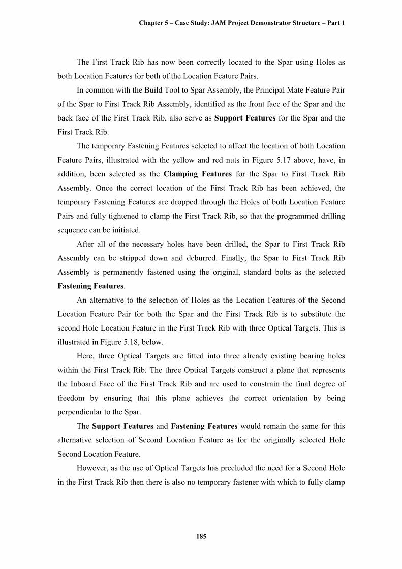
An alternative to the selection of Holes as the Location Features of the Second
Location Feature Pair for both the Spar and the First Track Rib is to substitute the
second Hole Location Feature in the First Track Rib with three Optical Targets. This is
illustrated in Figure 5.18, below.
Here, three Optical Targets are fitted into three already existing bearing holes
within the First Track Rib. The three Optical Targets construct a plane that represents
the Inboard Face of the First Track Rib and are used to constrain the final degree of
freedom by ensuring that this plane achieves the correct orientation by being
perpendicular to the Spar.
The Support Features and Fastening Features would remain the same for this
alternative selection of Second Location Feature as for the originally selected Hole
Second Location Feature.
However, as the use of Optical Targets has precluded the need for a Second Hole
in the First Track Rib then there is also no temporary fastener with which to fully clamp
Chapter 5 – Case Study: JAM Project Demonstrator Structure – Part 1
186
the First Track Rib with prior to drilling. Therefore, an extra clamp would have to be
used to clamp the First Track Rib and its Clamping Features could be selected.
Examples of different types of Optical Targets can be found in the Feature Library
for Jigless Assembly in Appendix B. The selected Optical Targets would have to be
used in conjunction with some type of measurement apparatus, as introduced earlier in
the chapter. Examples of measurement apparatus could be a Laser, Autocollimator,
Theodolite, or indeed, any other appropriate system, some of which are referenced in
the Feature Library for Jigless Assembly.
As highlighted in section 5.4.1.3, the selection of ‘measurement-assisted’
assembly using metrology apparatus with its associated Location Features was outside
of the scope for the JAM Project. Nevertheless, there are numerous advantages and
disadvantages to the adoption of measurement-assisted assembly. It can be argued that
if it were to be adopted then it would be more beneficial to fully embrace the technology
by removing all of the part-integrated and therefore product-specific, type Location
Features, i.e. the Hole Location Features, so that the First Track Rib would be entirely
located by the measurement apparatus, after which, it could be supported, clamped and
fastened in the usual way.
It is clear, though, that there would be many issues concerning the adoption of
measurement-assisted assembly.
The selection of the specific Location Features for the measurement apparatus
would be subject to the same Design and Manufacturing criteria and use the same tools
of Feature Based Costing and Error Budgeting to evaluate and compare different
metrology Location Features, as the Location Feature Selection Process used for
conventional type Location Features.
Yet these metrological type Location Features will have their own set of distinct
parameters and attributes that are not directly comparable with more conventional hard,
part-integrated type Location Features. This situation is also applicable for the selection
of the measurement apparatus, itself, as the specifications and usage of common tooling
are quite different from that of measurement systems.
Chapter 5 – Case Study: JAM Project Demonstrator Structure – Part 1
187
OpticalTarget
LaserAutocollimator Theodolite
1
2
3
Figure 5.18 Optical Target Location Features
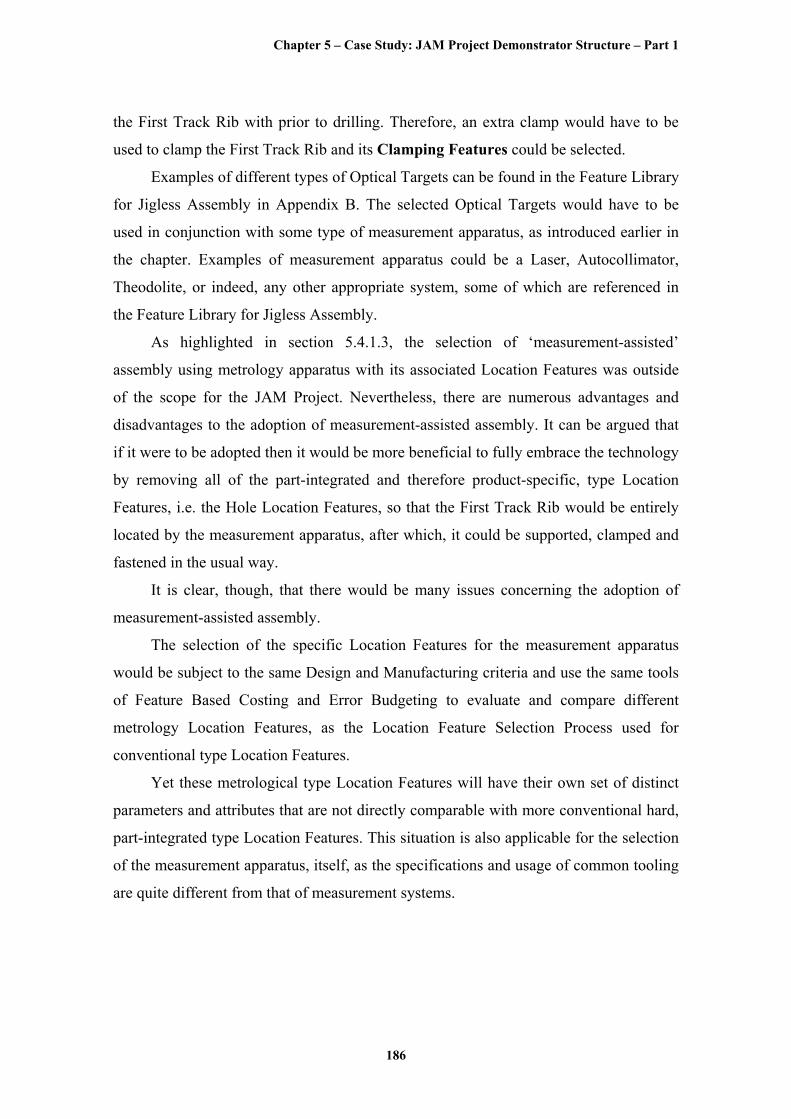
5.4.3 Assembly Stage 3: Spar to Inter Rib Assembly
5.4.3.1 Description of Assembly Stage 3
Figure 5.19, below, shows the initial operation of the Spar to Inter Rib Assembly.
Similar to the assembly of the First Track Rib, the Inter Rib is placed on the Spar.
Assembly features are selected to locate, support and clamp the Inter Rib to the Spar.
However, unlike the First Track Rib, the Inter Rib is not fastened at this stage because it
was deemed that the Spar was too flexible to be sure that both Track and Inter Ribs
were in alignment, one of the prerequisites to achieve the Product Key Characteristics
listed in Table 5.1. Hence, the Inter Rib is left located, supported and clamped ready to
be manually adjusted to be in alignment with the two Track Ribs at a later assembly
stage.
Chapter 5 – Case Study: JAM Project Demonstrator Structure – Part 1
188
First Location Feature
Pair
Figure 5.19 Spar to Inter Rib Assembly
5.4.3.2 Feature Selection Process for Assembly Stage 3
The Principal Mate Feature Pairs for Assembly Stage 3 were identified to be
the front face of the Spar and the back face of the Inter Rib.
The degrees of freedom constrained by the Principal Mate Feature Pair in this axis
system will be:-
• Tz, Rx and Ry
As the Principal Mate Feature Pairs have been identified, the Location Feature
Pairs can be selected.
The remaining degrees of freedom that need to be constrained by the selected
Location Feature Pairs are:-
• Tx, Ty and Rz
Chapter 5 – Case Study: JAM Project Demonstrator Structure – Part 1
189
The Location Feature Pair selection process for the Spar to Inter Rib Assembly
followed exactly the same arguments in the selection process as for the Spar to First
Track Rib Assembly.
An illustration of the selected First Location Feature Pair of a Hole Location
Feature for the Spar and a Hole Location Feature for the Inter Rib, to constrain the two
degrees of freedom, Tx and Ty, is shown in Figure 5.19, above. An illustration of the
selected Second Location Feature Pair of a Hole Location Feature for the Spar and a
Hole Location Feature for the Inter Rib, to constrain the final degree of freedom, Rz, is
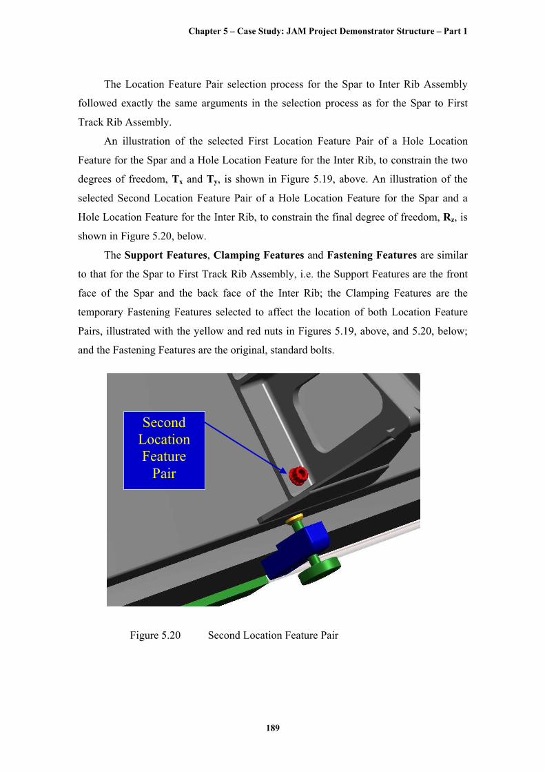
shown in Figure 5.20, below.
The Support Features, Clamping Features and Fastening Features are similar
to that for the Spar to First Track Rib Assembly, i.e. the Support Features are the front
face of the Spar and the back face of the Inter Rib; the Clamping Features are the
temporary Fastening Features selected to affect the location of both Location Feature
Pairs, illustrated with the yellow and red nuts in Figures 5.19, above, and 5.20, below;
and the Fastening Features are the original, standard bolts.
Second Location Feature
Pair
Figure 5.20 Second Location Feature Pair
Chapter 5 – Case Study: JAM Project Demonstrator Structure – Part 1
190
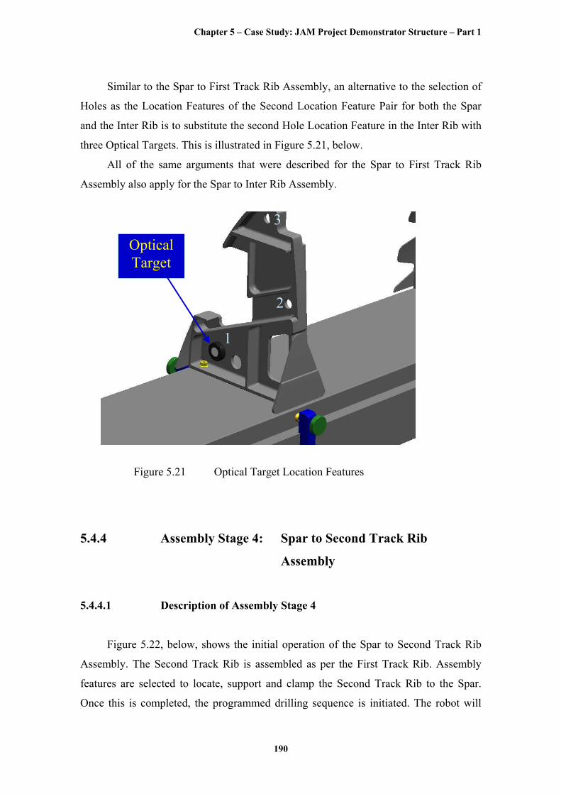
Similar to the Spar to First Track Rib Assembly, an alternative to the selection of
Holes as the Location Features of the Second Location Feature Pair for both the Spar
and the Inter Rib is to substitute the second Hole Location Feature in the Inter Rib with
three Optical Targets. This is illustrated in Figure 5.21, below.
All of the same arguments that were described for the Spar to First Track Rib
Assembly also apply for the Spar to Inter Rib Assembly.
OpticalTarget
1
2
3
Figure 5.21 Optical Target Location Features
5.4.4 Assembly Stage 4: Spar to Second Track Rib
Assembly
5.4.4.1 Description of Assembly Stage 4
Figure 5.22, below, shows the initial operation of the Spar to Second Track Rib
Assembly. The Second Track Rib is assembled as per the First Track Rib. Assembly
features are selected to locate, support and clamp the Second Track Rib to the Spar.
Once this is completed, the programmed drilling sequence is initiated. The robot will

Chapter 5 – Case Study: JAM Project Demonstrator Structure – Part 1
191
drill through from below, using a fitted machine vision device, i.e. a Remote Centre
Compliance device that ensures alignment with the location features in the Spar. The
Spar to Second Track Rib assembly is stripped down, deburred, and reassembled using
the selected fastening features.
1st Track Rib
2nd Track Rib
Inter Rib First
Location Feature
Pair
Figure 5.22 Spar to Second Track Rib Assembly
5.4.4.2 Feature Selection Process for Assembly Stage 4
The Principal Mate Feature Pairs for Assembly Stage 4 were identified to be
the front face of the Spar and the back face of the Second Track Rib.
The degrees of freedom constrained by the Principal Mate Feature Pair in this axis
system will be:-
• Tz, Rx and Ry
As the Principal Mate Feature Pairs have been identified, the Location Feature
Pairs can be selected.
Chapter 5 – Case Study: JAM Project Demonstrator Structure – Part 1
192
The remaining degrees of freedom that need to be constrained by the selected
Location Feature Pairs are:-
• Tx, Ty and Rz
Again, the Location Feature Pair selection process for the Spar to Second Track
Rib Assembly followed exactly the same arguments in the selection process as for the
Spar to First Track Rib Assembly.
An illustration of the selected First Location Feature Pair of a Hole Location
Feature for the Spar and a Hole Location Feature for the Second Track Rib, to constrain
the two degrees of freedom, Tx and Ty, is shown in Figure 5.22, above. An illustration
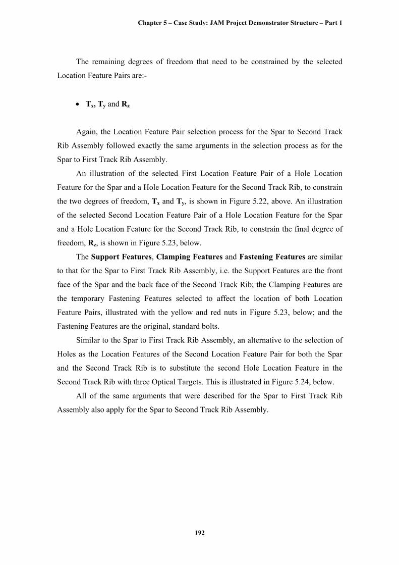
of the selected Second Location Feature Pair of a Hole Location Feature for the Spar
and a Hole Location Feature for the Second Track Rib, to constrain the final degree of
freedom, Rz, is shown in Figure 5.23, below.
The Support Features, Clamping Features and Fastening Features are similar
to that for the Spar to First Track Rib Assembly, i.e. the Support Features are the front
face of the Spar and the back face of the Second Track Rib; the Clamping Features are
the temporary Fastening Features selected to affect the location of both Location
Feature Pairs, illustrated with the yellow and red nuts in Figure 5.23, below; and the
Fastening Features are the original, standard bolts.
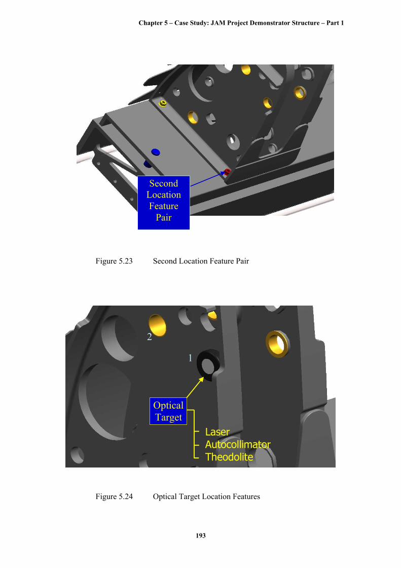
Similar to the Spar to First Track Rib Assembly, an alternative to the selection of
Holes as the Location Features of the Second Location Feature Pair for both the Spar
and the Second Track Rib is to substitute the second Hole Location Feature in the
Second Track Rib with three Optical Targets. This is illustrated in Figure 5.24, below.
All of the same arguments that were described for the Spar to First Track Rib
Assembly also apply for the Spar to Second Track Rib Assembly.
Chapter 5 – Case Study: JAM Project Demonstrator Structure – Part 1
193
Second Location Feature
Pair
Figure 5.23 Second Location Feature Pair
OpticalTarget
1
2
LaserAutocollimatorTheodolite
Figure 5.24 Optical Target Location Features
Chapter 5 – Case Study: JAM Project Demonstrator Structure – Part 1
194
5.4.5 Assembly Stage 5: Track and Inter Rib Alignment
5.4.5.1 Description of Assembly Stage 5
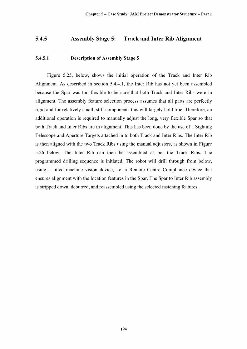
Figure 5.25, below, shows the initial operation of the Track and Inter Rib
Alignment. As described in section 5.4.4.1, the Inter Rib has not yet been assembled
because the Spar was too flexible to be sure that both Track and Inter Ribs were in
alignment. The assembly feature selection process assumes that all parts are perfectly
rigid and for relatively small, stiff components this will largely hold true. Therefore, an
additional operation is required to manually adjust the long, very flexible Spar so that
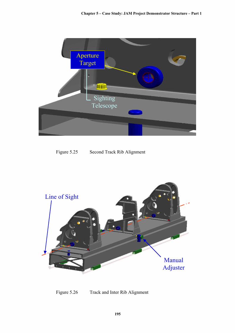
both Track and Inter Ribs are in alignment. This has been done by the use of a Sighting
Telescope and Aperture Targets attached in to both Track and Inter Ribs. The Inter Rib
is then aligned with the two Track Ribs using the manual adjusters, as shown in Figure
5.26 below. The Inter Rib can then be assembled as per the Track Ribs. The
programmed drilling sequence is initiated. The robot will drill through from below,
using a fitted machine vision device, i.e. a Remote Centre Compliance device that
ensures alignment with the location features in the Spar. The Spar to Inter Rib assembly
is stripped down, deburred, and reassembled using the selected fastening features.
Chapter 5 – Case Study: JAM Project Demonstrator Structure – Part 1
195
Aperture Target
Sighting Telescope
Figure 5.25 Second Track Rib Alignment
Manual Adjuster
Line of Sight
Figure 5.26 Track and Inter Rib Alignment
Chapter 5 – Case Study: JAM Project Demonstrator Structure – Part 1
196
5.4.6 Assembly Stage 6: First Track and Inter Ribs to
First Sub-Spar Assembly
5.4.6.1 Description of Assembly Stage 6
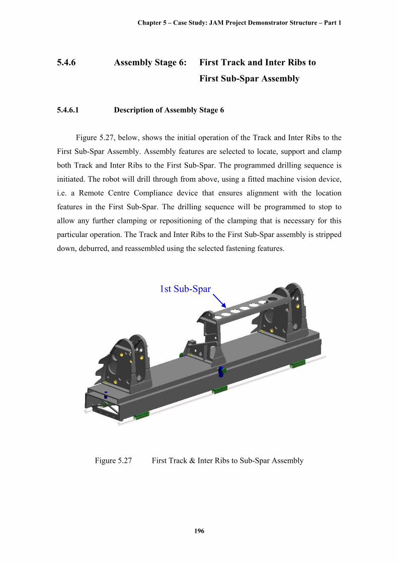
Figure 5.27, below, shows the initial operation of the Track and Inter Ribs to the
First Sub-Spar Assembly. Assembly features are selected to locate, support and clamp
both Track and Inter Ribs to the First Sub-Spar. The programmed drilling sequence is
initiated. The robot will drill through from above, using a fitted machine vision device,
i.e. a Remote Centre Compliance device that ensures alignment with the location
features in the First Sub-Spar. The drilling sequence will be programmed to stop to
allow any further clamping or repositioning of the clamping that is necessary for this
particular operation. The Track and Inter Ribs to the First Sub-Spar assembly is stripped
down, deburred, and reassembled using the selected fastening features.
1st Sub-Spar
Figure 5.27 First Track & Inter Ribs to Sub-Spar Assembly
Chapter 5 – Case Study: JAM Project Demonstrator Structure – Part 1
197
5.4.6.2 Feature Selection Process for Assembly Stage 6
The Principal Mate Feature Pairs for Assembly Stage 6 were identified to be
the front face of both Track and Inter Ribs Sub-Spars’ Flanges and the back face of the
First Sub-Spars’ Flanges.
The degrees of freedom constrained by the Principal Mate Feature Pair in this axis
system will be:-
• Tz, Rx and Ry
As the Principal Mate Feature Pairs have been identified, the Location Feature
Pairs can be selected.
The remaining degrees of freedom that need to be constrained by the selected
Location Feature Pairs are:-
• Tx, Ty and Rz
Again, the Location Feature Pair selection process for the Track and Inter Ribs to
First Sub-Spar Assembly followed exactly the same arguments in the selection process
as for the Spar to First Track Rib Assembly.
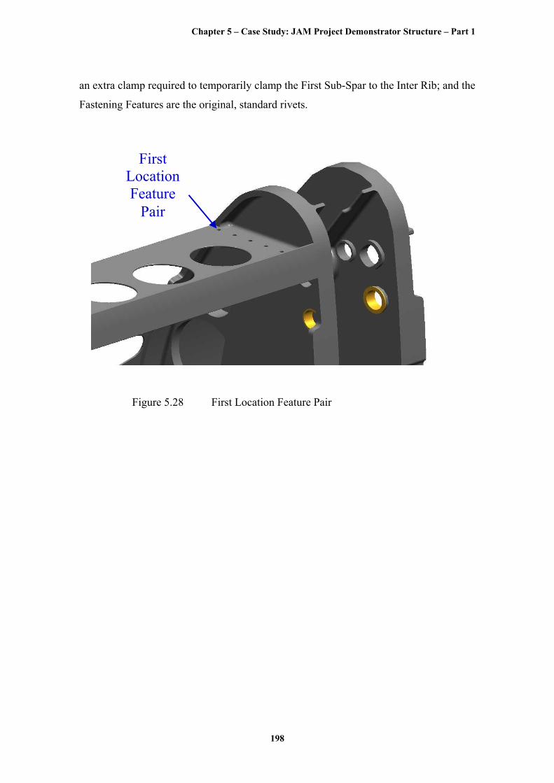
An illustration of the selected First Location Feature Pair of a Hole Location
Feature for the First Track Rib and a Hole Location Feature for the First Sub-Spar, to
constrain the two degrees of freedom, Tx and Ty, is shown in Figure 5.28, below. An
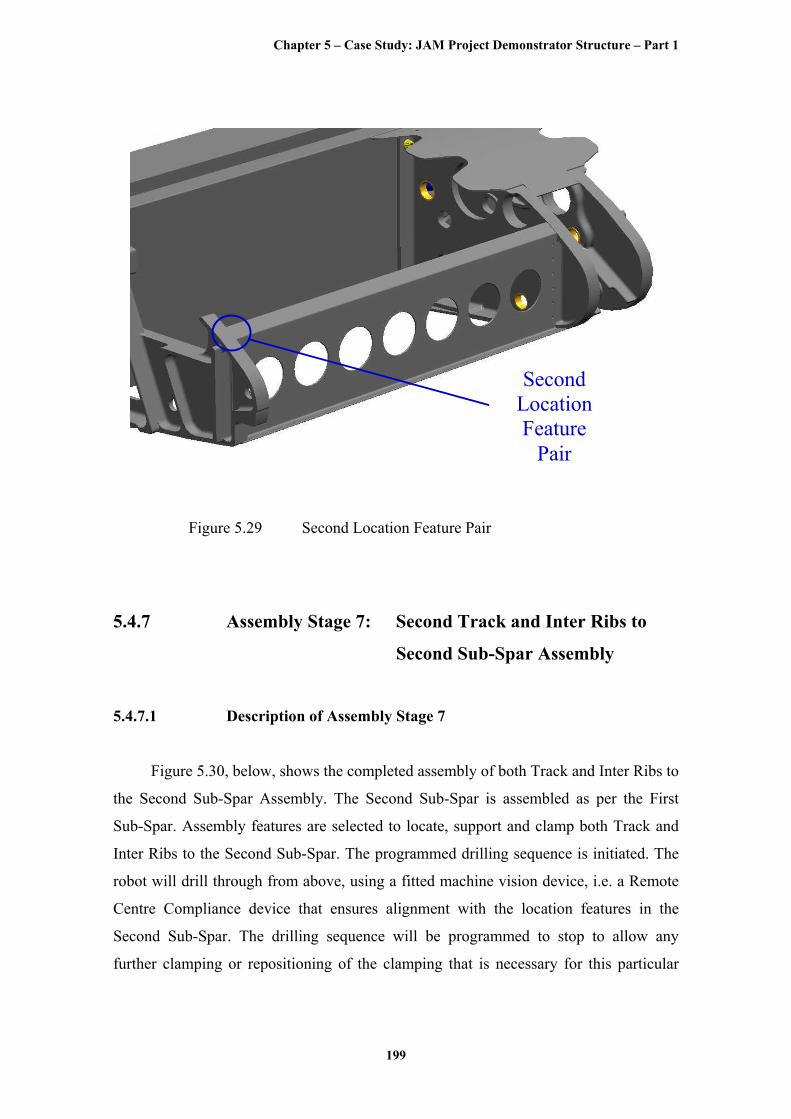
illustration of the selected Second Location Feature Pair of an Edge Location Feature
for the Inter Rib and an Edge Location Feature for the First Sub-Spar, to constrain the
final degree of freedom, Rz, is shown in Figure 5.29, below.
The Support Features, Clamping Features and Fastening Features are similar
to that for the Spar to First Track Rib Assembly, i.e. the Support Features are the front
faces of the First Track and Inter Rib Sub-Spar Flanges and the back faces of the First
Sub-Spar Flanges; the Clamping Features are the temporary Fastening Features selected
to affect the location of the First Location Feature Pair and also the clamping features of
Chapter 5 – Case Study: JAM Project Demonstrator Structure – Part 1
198
an extra clamp required to temporarily clamp the First Sub-Spar to the Inter Rib; and the
Fastening Features are the original, standard rivets.
First Location Feature
Pair
Figure 5.28 First Location Feature Pair
Chapter 5 – Case Study: JAM Project Demonstrator Structure – Part 1
199
Second Location Feature
Pair
Figure 5.29 Second Location Feature Pair
5.4.7 Assembly Stage 7: Second Track and Inter Ribs to
Second Sub-Spar Assembly
5.4.7.1 Description of Assembly Stage 7
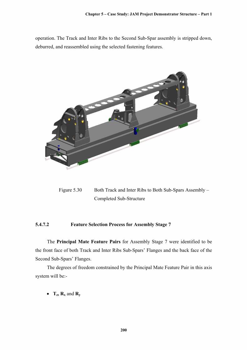
Figure 5.30, below, shows the completed assembly of both Track and Inter Ribs to
the Second Sub-Spar Assembly. The Second Sub-Spar is assembled as per the First
Sub-Spar. Assembly features are selected to locate, support and clamp both Track and
Inter Ribs to the Second Sub-Spar. The programmed drilling sequence is initiated. The
robot will drill through from above, using a fitted machine vision device, i.e. a Remote
Centre Compliance device that ensures alignment with the location features in the
Second Sub-Spar. The drilling sequence will be programmed to stop to allow any
further clamping or repositioning of the clamping that is necessary for this particular
Chapter 5 – Case Study: JAM Project Demonstrator Structure – Part 1
200
operation. The Track and Inter Ribs to the Second Sub-Spar assembly is stripped down,
deburred, and reassembled using the selected fastening features.
Figure 5.30 Both Track and Inter Ribs to Both Sub-Spars Assembly –
Completed Sub-Structure
5.4.7.2 Feature Selection Process for Assembly Stage 7
The Principal Mate Feature Pairs for Assembly Stage 7 were identified to be
the front face of both Track and Inter Ribs Sub-Spars’ Flanges and the back face of the
Second Sub-Spars’ Flanges.
The degrees of freedom constrained by the Principal Mate Feature Pair in this axis
system will be:-
• Tz, Rx and Ry
Chapter 5 – Case Study: JAM Project Demonstrator Structure – Part 1
201
As the Principal Mate Feature Pairs have been identified, the Location Feature
Pairs can be selected.
The remaining degrees of freedom that need to be constrained by the selected
Location Feature Pairs are:-
• Tx, Ty and Rz
Again, the Location Feature Pair selection process for the Track and Inter Ribs to
Second Sub-Spar Assembly followed exactly the same arguments in the selection
process as for the Spar to First Track Rib Assembly.
A Hole Location Feature for the Second Track Rib and a Hole Location Feature
for the Second Sub-Spar, to constrain the two degrees of freedom, Tx and Ty were
selected as the First Location Feature Pair. An Edge Location Feature for the Inter Rib
and an Edge Location Feature for the Second Sub-Spar, to constrain the final degree of
freedom, Rz was selected as the Second Location Feature Pair.
The Support Features, Clamping Features and Fastening Features are similar
to that for the Spar to First Track Rib Assembly, i.e. the Support Features are the front
faces of the Second Track and Inter Rib Sub-Spar Flanges and the back faces of the
Second Sub-Spar Flanges; the Clamping Features are the temporary Fastening Features
selected to affect the location of the First Location Feature Pair and also the clamping
features of an extra clamp required to temporarily clamp the Second Sub-Spar to the
Inter Rib; and the Fastening Features are the original, standard rivets.
5.4.8 Assembly Stage 8: Second Track Rib and Spar to
Skin Assembly
5.4.8.1 Description of Assembly Stage 8
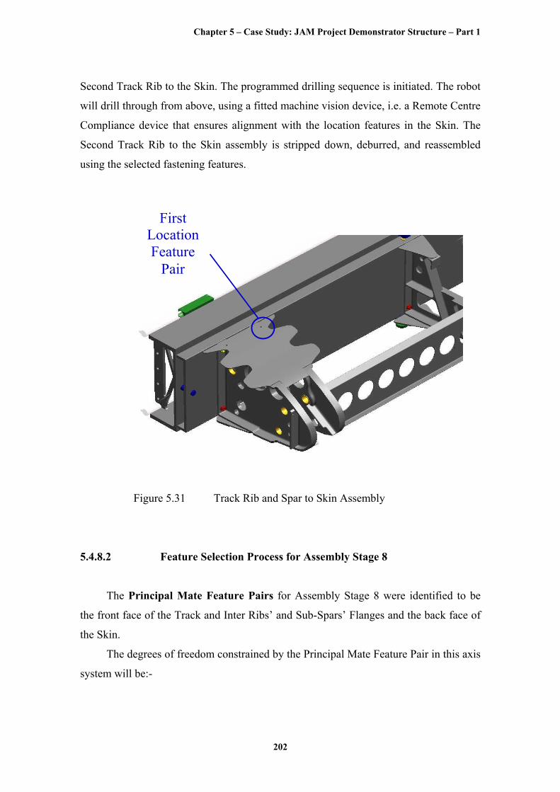
Figure 5.31, below, shows the initial operation of the Second Track Rib and Spar
to Skin Assembly. Assembly features are selected to locate, support and clamp the
Chapter 5 – Case Study: JAM Project Demonstrator Structure – Part 1
202
Second Track Rib to the Skin. The programmed drilling sequence is initiated. The robot
will drill through from above, using a fitted machine vision device, i.e. a Remote Centre
Compliance device that ensures alignment with the location features in the Skin. The
Second Track Rib to the Skin assembly is stripped down, deburred, and reassembled
using the selected fastening features.
First Location Feature
Pair
Figure 5.31 Track Rib and Spar to Skin Assembly
5.4.8.2 Feature Selection Process for Assembly Stage 8
The Principal Mate Feature Pairs for Assembly Stage 8 were identified to be
the front face of the Track and Inter Ribs’ and Sub-Spars’ Flanges and the back face of
the Skin.
The degrees of freedom constrained by the Principal Mate Feature Pair in this axis
system will be:-
Chapter 5 – Case Study: JAM Project Demonstrator Structure – Part 1
203
• Ty, Tz, Rx, Ry, and Rz
As the Principal Mate Feature Pairs have been identified, the Location Feature
Pairs can be selected.
The remaining degree of freedom that needs to be constrained by the selected
Location Feature Pairs is:-
• Tx
Again, the Location Feature Pair selection process for the Second Track Rib and
Spar to Skin Assembly followed exactly the same arguments in the selection process as
for the Spar to First Track Rib Assembly.
An illustration of the selected First Location Feature Pair of a Hole Location
Feature for the Second Track Rib and a Hole Location Feature for the Skin, to constrain
the final degree of freedom, Tx, is shown in Figure 5.31, above.
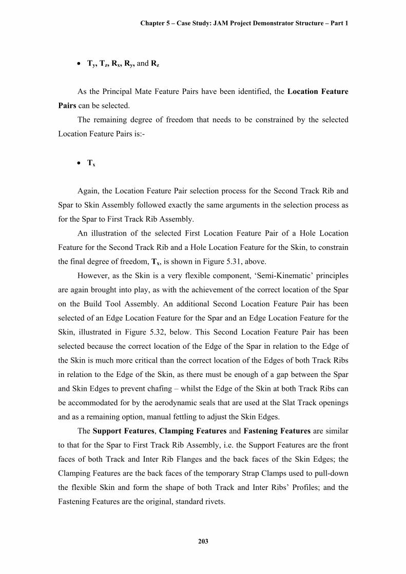
However, as the Skin is a very flexible component, ‘Semi-Kinematic’ principles
are again brought into play, as with the achievement of the correct location of the Spar
on the Build Tool Assembly. An additional Second Location Feature Pair has been
selected of an Edge Location Feature for the Spar and an Edge Location Feature for the
Skin, illustrated in Figure 5.32, below. This Second Location Feature Pair has been
selected because the correct location of the Edge of the Spar in relation to the Edge of
the Skin is much more critical than the correct location of the Edges of both Track Ribs
in relation to the Edge of the Skin, as there must be enough of a gap between the Spar
and Skin Edges to prevent chafing – whilst the Edge of the Skin at both Track Ribs can
be accommodated for by the aerodynamic seals that are used at the Slat Track openings
and as a remaining option, manual fettling to adjust the Skin Edges.
The Support Features, Clamping Features and Fastening Features are similar
to that for the Spar to First Track Rib Assembly, i.e. the Support Features are the front
faces of both Track and Inter Rib Flanges and the back faces of the Skin Edges; the
Clamping Features are the back faces of the temporary Strap Clamps used to pull-down
the flexible Skin and form the shape of both Track and Inter Ribs’ Profiles; and the
Fastening Features are the original, standard rivets.
Chapter 5 – Case Study: JAM Project Demonstrator Structure – Part 1
204
Second Location Feature
Pair
Figure 5.32 Second Location Feature Pair
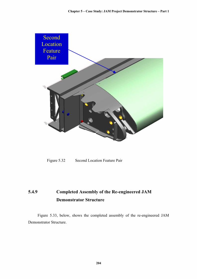
5.4.9 Completed Assembly of the Re-engineered JAM
Demonstrator Structure
Figure 5.33, below, shows the completed assembly of the re-engineered JAM
Demonstrator Structure.
Chapter 5 – Case Study: JAM Project Demonstrator Structure – Part 1
205
Figure 5.33 Completed assembly of the re-engineered JAM
Demonstrator Structure


![17.06 - Technische Universität München1]:accessed 27th January 2016) ... My Joghurt–accepted Industrie4.0 demonstrator Demonstrator: ...](https://static.fdocuments.in/doc/165x107/5ab574077f8b9ab7638cc5ad/1706-technische-universitt-mnchen-1-accessed-27th-january-2016-my-joghurtaccepted.jpg)