
5 3 1 - mmcontrol.com · PS531 V5 May 2002 5 3 1 5 3 1 PLC, DCS, PC CONTROL BACKUP STATION The...
6
PS531 V5 May 2002 5 3 1 5 3 1 PLC, DCS, PC CONTROL BACKUP STATION The Interface Solution Experts www.miinet.com Auto/Manual Station Hot PID Backup Station The Interface Solution Experts NOW A PRODUCT! M&M Control Service, INC. 800-876-0036 M&M Control Service, INC. 800-876-0036
Transcript of 5 3 1 - mmcontrol.com · PS531 V5 May 2002 5 3 1 5 3 1 PLC, DCS, PC CONTROL BACKUP STATION The...

PS531 V5 May 2002
5 3 1
5 3 1
PLC, DCS, PC CONTROL BACKUP STATION
The Interface Solution Expertswww.miinet.com
Auto/Manual Station
Hot PID Backup Station
The Interface Solution Experts
NOW A
PRODUCT!
M&M Control Service, INC. 800-876-0036
M&M Control Service, INC. 800-876-0036

Page 2 PS531 V5
FEATURES• Optically isolated inputs and outputs to
avoid ground loop problems.• Unique, bolted “clamshell” front panel
provides NEMA 4X watertight rating.• Sturdy illuminated rubber keys yield
much longer life than common dome-typekeys, provide excellent tactile feel, andare easily read in the dark.
• Bright vacuum fluorescent three linedisplay has two lines of alpha-numericsfor simplified configuration and operationmessages.
• Compact 6" deep case enablesinstallation in shallow cabinet.
• Available alarm output in LOCAL modefor status flag to host.
• Optional RS-485 serial communicationswith baud rates up to 19,200 will allowyou to monitor your process from apersonal computer or other host.
PURPOSE AND OPERATIONThe 531 provides automatic PID control backup for critical loopscontrolled by PLC, DCS or PC systems. Unlike a single loopcontroller configured to sense and retransmit a control signal,which adds liability and complexity; the 531 has a simpleoperator interface, special parameters for control states uponhost transfer or failure, and a special pass-through circuit thatprovides redundancy in the control loop. In HOST mode, thecontrol signal (4-20mA) is hard wired to pass through the 531without degradation. In LOCAL mode, the 531 generates the CV(control) signal in AUTO or MANUAL mode. Host CV trackingenables a bumpless transfer to LOCAL mode in either LOCALAUTO or LOCAL MANUAL mode. A special CV line sensefunction triggers HOST to LOCAL transfer automatically if hostCV signal fails. LOCAL/HOST transfer may also be initiated bya dedicated front panel key or a contact input. The 531's setpointmay be set locally or remotely from the host, ensuring bumplesschangeover to LOCAL AUTO mode. The 531 may also beoperated as a manual loading station in the LOCAL MANUALmode.
FUNCTIONSLoss of HostControl Signal
Local/HostTransfer
Control SignalIntegrity
Control SignalIntegrity
Ease ofConfiguration
Simplicity ofOperation
Universal ProcessInput
Security
CVline sense function triggers "Lost Host" message, automatic transfer to LOCALmode; bumpless transfer with RSP tracking available. Automatic transfer to HOSTmode upon host CV return is configurable (CV must be 4-20mA signal).
Dedicated "Host" key toggles between states and lights in HOST mode. Bumplesstransfer to either LOCAL AUTO or LOCAL MANUAL mode is available by using RSPtracking and output ramp. Transfer also initiatable by rear contact.
"Hard Wired" pass-through circuit does not rely on local station (531) to generatecontrol signal in HOST mode.
Special "By-Pass" circuit allows host control signal to pass through even when 531chassis is removed from case.
Special menus and parameters dedicated to back-up function enable configuration ofoutput and setpoint states upon "Host" failure or operator initiated transfer.
Clearly labeled keys and displays enable operators to easily see control loop status:HOST/LOCAL mode, AUTO/MANUAL mode, PV, CV, host and local SP.
PV signal may be retransmitted from host or in series with host. Thermocouple,RTD, volt and mV signals may be direct wired to 531.
Our unique security system lets you decide exactly which function groups haverestricted access.
M&M Control Service, INC. 800-876-0036
M&M Control Service, INC. 800-876-0036
PS531 V5 Page 3
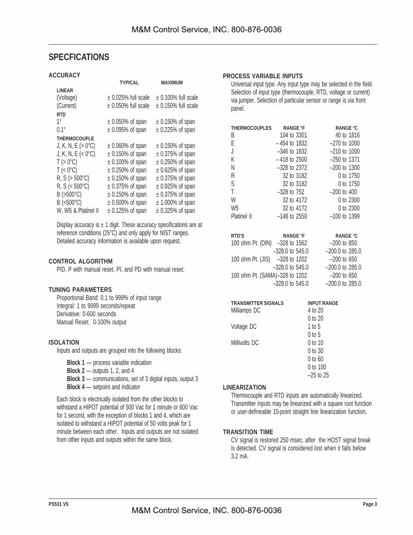
SPECFICATIONS
ACCURACY TYPICAL MAXIMUM
LINEAR(Voltage) ± 0.025% full scale ± 0.100% full scale(Current) ± 0.050% full scale ± 0.150% full scaleRTD1° ± 0.050% of span ± 0.150% of span0.1° ± 0.095% of span ± 0.225% of spanTHERMOCOUPLEJ, K, N, E (> 0°C) ± 0.060% of span ± 0.150% of spanJ, K, N, E (< 0°C) ± 0.150% of span ± 0.375% of spanT (> 0°C) ± 0.100% of span ± 0.250% of spanT (< 0°C) ± 0.250% of span ± 0.625% of spanR, S (> 500°C) ± 0.150% of span ± 0.375% of spanR, S (< 500°C) ± 0.375% of span ± 0.925% of spanB (>500°C) ± 0.150% of span ± 0.375% of spanB (<500°C) ± 0.500% of span ± 1.000% of spanW, W5 & Platinel II ± 0.125% of span ± 0.325% of span
Display accuracy is ± 1 digit. These accuracy specifications are atreference conditions (25°C) and only apply for NIST ranges.Detailed accuracy information is available upon request.
CONTROL ALGORITHMPID, P with manual reset, PI, and PD with manual reset.
TUNING PARAMETERSProportional Band: 0.1 to 999% of input rangeIntegral: 1 to 9999 seconds/repeatDerivative: 0-600 secondsManual Reset: 0-100% output
ISOLATIONInputs and outputs are grouped into the following blocks:
Block 1 — process variable indicationBlock 2 — outputs 1, 2, and 4Block 3 — communications, set of 3 digital inputs, output 3Block 4 — setpoint and indicator
Each block is electrically isolated from the other blocks towithstand a HIPOT potential of 500 Vac for 1 minute or 600 Vacfor 1 second, with the exception of blocks 1 and 4, which areisolated to withstand a HIPOT potential of 50 volts peak for 1minute between each other. Inputs and outputs are not isolatedfrom other inputs and outputs within the same block.
PROCESS VARIABLE INPUTSUniversal input type. Any input type may be selected in the field.Selection of input type (thermocouple, RTD, voltage or current)via jumper. Selection of particular sensor or range is via frontpanel.
THERMOCOUPLES RANGE °F RANGE °CB 104 to 3301 40 to 1816E – 454 to 1832 –270 to 1000J –346 to 1832 –210 to 1000K – 418 to 2500 –250 to 1371N –328 to 2372 –200 to 1300R 32 to 3182 0 to 1750S 32 to 3182 0 to 1750T –328 to 752 –200 to 400W 32 to 4172 0 to 2300W5 32 to 4172 0 to 2300Platinel II –148 to 2550 –100 to 1399
RTD'S RANGE °F RANGE °C100 ohm Pt. (DIN) –328 to 1562 –200 to 850
–328.0 to 545.0 –200.0 to 285.0100 ohm Pt. (JIS) –328 to 1202 –200 to 650
–328.0 to 545.0 –200.0 to 285.0100 ohm Pt. (SAMA)–328 to 1202 –200 to 650
–328.0 to 545.0 –200.0 to 285.0
TRANSMITTER SIGNALS INPUT RANGEMilliamps DC 4 to 20
0 to 20Voltage DC 1 to 5
0 to 5Millivolts DC 0 to 10
0 to 300 to 600 to 100–25 to 25
LINEARIZATIONThermocouple and RTD inputs are automatically linearized.Transmitter inputs may be linearized with a square root functionor user-defineable 15-point straight line linearization function.
TRANSITION TIMECV signal is restored 250 msec. after the HOST signal breakis detected. CV signal is considered lost when it falls below3.2 mA.
M&M Control Service, INC. 800-876-0036
M&M Control Service, INC. 800-876-0036

Page 4 PS531 V5
INPUT IMPEDANCECurrent Input: 250 ohms Thermocouples: 10 MohmsVoltage Input: 1 Mohm RTDs: 10 Mohms
UPDATE RATEInput is sampled and output updated 5 times per second. Displayis updated 5 times per second. Passage of the HOST signalthrough the 531 is continuous.
INPUT FILTERSingle pole lowpass digital filter with selectable time constantfrom 0 to 120 seconds.
CALIBRATIONThe station comes fully calibrated from the factory and continuouslycalibrates itself for component aging due to temperature and time,except for reference voltage. Field calibration can be performedeasily with a precision multimeter and thermocouple simulator.Process variable offset and gain factors are provided to correct forsensor errors.
OUTPUT MODULESOne analog output (CV), 4–20 mA into a load up to 1000 ohm. Alsoavailable is an additional mechanical relay module that can be tied toan alarm.
CONTROL OUTPUTS4–20 mA into a load up to 1000 ohms.
ALARMSThe 531 has two powerful software alarms. The 531 provides aLOCAL alarm that indicates when the 531 is in LOCAL mode.When tied to an available output, the HOST device can beflagged as to the change in status. Alternately, a PV High, PVLow, PV Rate, SP Band or SP Deviation alarm may beconfigured. A 9-character custom alarm message is available foreach alarm.
DIGITAL INPUTSA set of five external dry contacts or open collector driventransistor inputs are available. Each can be configured to performone of the following functions:• Select LOCAL control with LAST-OUT or 1 of 2 preset values• Acknowledge alarms• Addressable through serial communications only• / Key Emulation• HOST "watchdog" timer input
SERIAL COMMUNICATIONSIsolated serial communications is available using an RS-485interface. Baud rates of up to 19,200 are selectable. Theprotocol supports CRC data checking.
DIGITAL DISPLAYSDisplayed information depends upon chosen options.Upper display: five-digit, seven-segment. Used exclusively todisplay PV. Height is 15 mm (0.6 in.).2nd display: nine-character, 14-segment alphanumeric. Select-able SP or CV indication. During set up, displays configurationinformation. Height is 6 mm (0.25 in.).3rd display: nine-character, 14-segment alphanumeric. When noalarm messages are queued, indicates a user-selectable "station"name. During set up, displays configuration information. Height is6 mm (0.25 in.).All displays are vacuum fluorescent. Color is blue-green.
STATUS INDICATORSALM 1 icon illuminated: alarm statusHOST key illuminated: CV signal from HOST is presentMANUAL key illuminated: 531 is in LOCAL MANUAL modeACK key illuminated: alarm is acknowledgableMENU key illuminated: 531 is in configuration mode
DIMENSIONSMeets 1/4 DIN designation as specized in DIN standard number43 700. See diagram on page 5 for details.
MOUNTINGPanel-mounted. See diagram on page 5 for details.
WIRING CONNECTIONS30 screw terminals in the rear of the instrument.
POWER CONSUMPTION15 VA at 120 VAC, 60 Hz (typical).
WEIGHTApproximately 1 kg (2.2 lbs.).
AMBIENT TEMPERATUREOperative Limits: 0 to 50°C (32 to 122°F).Storage Limits: – 40 to 70°C (– 40 to 158°F).
RELATIVE HUMIDITY10 to 90%, non-condensing.
VOLTAGE AND FREQUENCYUniversal power supply: 90 to 250 VAC, 48 to 62 Hz.
NOISE IMMUNITYCommon mode rejection (process input): >120 dB.Normal mode rejection (process input): >80 dB.AC line is double filtered and transient protected. Internalsnubbers are provided for each relay output.
M&M Control Service, INC. 800-876-0036
M&M Control Service, INC. 800-876-0036

PS531 V5 Page 5
5 3 1
CONSTRUCTIONCase: extruded, non-perforated black anodized aluminum withABS plastic sleeve.Bezel: black plastic ABS.Chassis assembly: plug-in type.Keys: silicone rubber with diffusion printed graphics.NEMA rating: front panel conforms to NEMA 4X wheninstrument is properly installed.
AGENCY APPROVALS
LR 84603
DIMENSIONS
TYPICAL APPLICATION
MEMORY RETENTIONLithium battery maintains all programming for approximatelyten years.
SECURITYThere are two levels of access: restricted and full. A configurablecode is used to enter the full access level. Functions not availablein the restricted level are configurable.
(Heavy Industrial)
(Available as an option)
LISTED
4N66Process Control Equipment
M&M Control Service, INC. 800-876-0036
M&M Control Service, INC. 800-876-0036
Page 6 PS531 V5
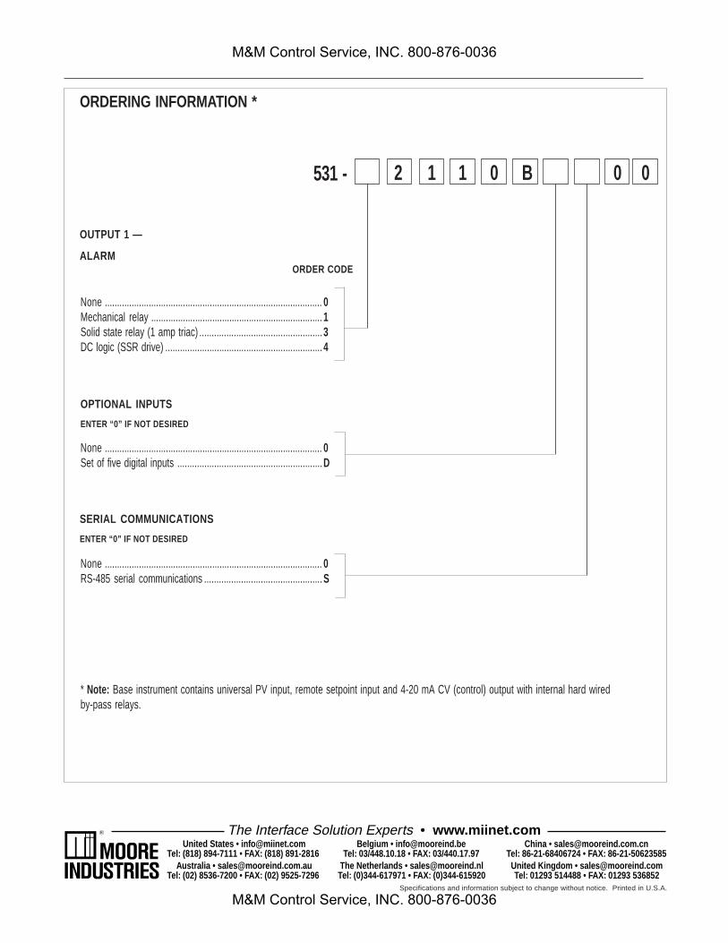
None ......................................................................................... 0Mechanical relay ...................................................................... 1Solid state relay (1 amp triac) ..................................................3DC logic (SSR drive) ................................................................4
None ......................................................................................... 0Set of five digital inputs ...........................................................D
None ......................................................................................... 0RS-485 serial communications ................................................S
ORDERING INFORMATION *
531 - 11 0 B 0 0
OUTPUT 1 —
ALARM
2
* Note: Base instrument contains universal PV input, remote setpoint input and 4-20 mA CV (control) output with internal hard wiredby-pass relays.
OPTIONAL INPUTS
ENTER “0” IF NOT DESIRED
ORDER CODE
SERIAL COMMUNICATIONS
ENTER “0” IF NOT DESIRED
The Interface Solution Experts • www.miinet.comUnited States • [email protected]
Tel: (818) 894-7111 • FAX: (818) 891-2816 Australia • [email protected]
Tel: (02) 8536-7200 • FAX: (02) 9525-7296
Belgium • [email protected]: 03/448.10.18 • FAX: 03/440.17.97
The Netherlands • [email protected]: (0)344-617971 • FAX: (0)344-615920
China • [email protected]: 86-21-68406724 • FAX: 86-21-50623585
United Kingdom • [email protected]: 01293 514488 • FAX: 01293 536852
Specifications and information subject to change without notice. Printed in U.S.A.
M&M Control Service, INC. 800-876-0036
M&M Control Service, INC. 800-876-0036