48510 10 ch10 p10-1-10-18 1. - Cengage · the interaction between a piston, a connecting rod, and a...
18
CHAPTER 10 Parametric Drawing Using Constraints PROJECT EXERCISE This project exercise provides point-by-point instructions for creating the objects shown in Figure P10–1. In this exercise, you will apply the skills acquired in Chapters 1 through 10. The purpose of this project is to demonstrate how constraints can be used to simulate the interaction between a piston, a connecting rod, and a crankshaft in a reciprocating engine. When the drawing is completed, if either end of the connecting rod is moved, the other end stays on the path intended. The crankshaft end will always stay on the circle that describes the path of the journal. The piston end will always stay on the line that describes the path of the piston and the piston will stay connected to the rod. In this project, you will learn to do the following: • Apply geometric constraints to objects. • Apply dimensional constraints to objects. FIGURE P10–1 Completed project drawing 10-1 © 2012 Delmar, Cengage Learning. All Rights Reserved. May not be scanned, copied or duplicated, or posted to a publicly accessible website, in whole or in part.
Transcript of 48510 10 ch10 p10-1-10-18 1. - Cengage · the interaction between a piston, a connecting rod, and a...

CHAPTER
10Parametric DrawingUsing Constraints
PROJECT EXERCISE
This project exercise provides point-by-point instructions for creating the objects shown inFigure P10–1. In this exercise, you will apply the skills acquired in Chapters 1 through 10.
The purpose of this project is to demonstrate how constraints can be used to simulatethe interaction between a piston, a connecting rod, and a crankshaft in a reciprocatingengine. When the drawing is completed, if either end of the connecting rod is moved,the other end stays on the path intended. The crankshaft end will always stay on thecircle that describes the path of the journal. The piston end will always stay on the linethat describes the path of the piston and the piston will stay connected to the rod.
In this project, you will learn to do the following:
• Apply geometric constraints to objects.
• Apply dimensional constraints to objects.
FIGURE P10–1 Completed project drawing
10-1
© 2012 Delmar, Cengage Learning. All Rights Reserved. May not be scanned, copied or duplicated, or posted to a publicly accessible website, in whole or in part.

SET UP THE DRAWING AND DRAW A BORDERStep 1: Start the AutoCAD program.
Step 2: To create a new drawing, invoke the NEW command from the Quick Accesstoolbar. AutoCAD displays the Select template dialog box. Select acad.dwt asthe template file and choose Open. AutoCAD creates a new drawing.
Step 3: Invoke the LIMITS command, and set the limits to the lower left and upperright coordinates as shown in the Settings/Value table. Set the grid, snap, andltscale values as shown also.
Settings Value
UNITS DecimalLIMITS Lower left corner: �4,�4
Upper right corner: 12,4GRID 0.5LTSCALE 0.01LAYERS NAME COLOR LINETYPE
Conrod Yellow ContinuousConstruction Red ACAD_ISO03W100Journal Green ContinuousPiston Magenta Continuous
Step 4: Invoke the LAYER command from the Layers panel. AutoCAD displays theLayer Properties Manager dialog box. Create six layers, rename them asshown in the table, and assign the appropriate color and linetype.
Step 5: Set Construction as the current layer. Invoke the ZOOM ALL command todisplay the entire limits on screen.
Step 6: Invoke the CIRCLE command Center, Radius method from the Draw panelto draw the circle representing the path of the crankshaft journal, as shownin Figure P10–2.
Specify center point for circle or 0,0
Specify radius of circle or 2.75
Step 7: Invoke the LINE command from the Draw panel to draw a line from thecenter of the circle to the right of the circle.
Specify first point: 0,0
Specify next point or #4,0
Specify next point or (ENTER)
Step 8: Repeat the LINE command to draw a horizontal line on the right side of thecircle.
Specify first point: 5,0
Specify next point or #8.5,0
Specify next point or (ENTER)
© 2012 Delmar, Cengage Learning. All Rights Reserved. May not be scanned, copied or duplicated, or posted to a publicly accessible website, in whole or in part.
10-2

Step 9: Set Piston as the current layer.
Step 10: Draw the piston and piston pin hole as shown in Figure P10–3. Invoke theLINE command to draw four lines representing the piston.
Specify first point: 5.5,-1.5
Specify next point or #5.5,1.5
Specify next point or #10.5,1.5
Specify next point or #10.5,-1.5
Specify next point or c
Step 11: Invoke the CIRCLE command Center, Radius method to draw the circlerepresenting the piston end of the connecting rod.
Specify center point for circle or 8.5,0
Specify radius of circle or 0.5
Step 12: Set Journal as the current layer.
Step 13: Invoke the CIRCLE command Center, Radius method to draw the circlerepresenting the crankshaft journal as shown in Figure P10–4.
FIGURE P10–2 Construction Layer objects
FIGURE P10–3 Added lines outlining the piston and circle for piston pin
© 2012 Delmar, Cengage Learning. All Rights Reserved. May not be scanned, copied or duplicated, or posted to a publicly accessible website, in whole or in part.
Chap t e r 10 • Pa rame t r i c Draw ing U s i n g Con s t r a i n t s 10-3

Specify center point for circle or 0,2.75
Specify radius of circle or 0.5
Step 14: Set Conrod as the current layer.
Step 15: Invoke the LINE command to draw the line representing the connecting rodas shown in Figure P10–5.
Specify first point: 0,2.75
Specify next point or #8.5,0
Specify next point or (ENTER)
The previous steps created the objects to be used in the exercise. The nextsteps will be to apply constraints to control the movement of the objects.The crankshaft end of the connecting rod will be restricted to the path thatthe journal travels. The piston and the piston end of the connecting rod willbe restricted to the path that the piston pin travels.
FIGURE P10–4 Added circle for crankshaft journal
FIGURE P10–5 Line representing connection rod
© 2012 Delmar, Cengage Learning. All Rights Reserved. May not be scanned, copied or duplicated, or posted to a publicly accessible website, in whole or in part.
10-4
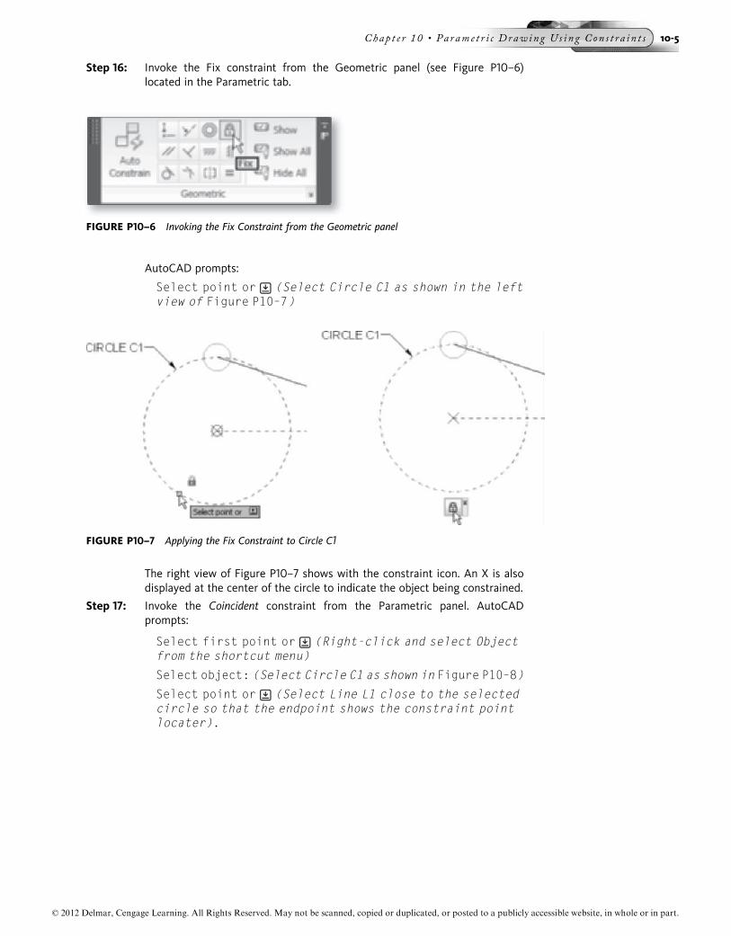
Step 16: Invoke the Fix constraint from the Geometric panel (see Figure P10–6)located in the Parametric tab.
AutoCAD prompts:
Select point or (Select Circle C1 as shown in the leftview of Figure P10–7)
The right view of Figure P10–7 shows with the constraint icon. An X is alsodisplayed at the center of the circle to indicate the object being constrained.
Step 17: Invoke the Coincident constraint from the Parametric panel. AutoCADprompts:
Select first point or (Right-click and select Objectfrom the shortcut menu)
Select object: (Select Circle C1 as shown in Figure P10–8)
Select point or (Select Line L1 close to the selectedcircle so that the endpoint shows the constraint pointlocater).
FIGURE P10–6 Invoking the Fix Constraint from the Geometric panel
FIGURE P10–7 Applying the Fix Constraint to Circle C1
© 2012 Delmar, Cengage Learning. All Rights Reserved. May not be scanned, copied or duplicated, or posted to a publicly accessible website, in whole or in part.
Chap t e r 10 • Pa rame t r i c Draw ing U s i n g Con s t r a i n t s 10-5

AutoCAD constrains the endpoint of the line to the path of the circle. A Coincidentconstraint icon is displayed where the line touches the circle.
NOTE If you select a circle in response to the first prompt to “Select point,” as in the application ofthe Fix constraint, AutoCAD uses the center of the circle as the constraint point. When youright-click and choose the Object option as the first selection, AutoCAD constrains the pointon the second item to the path of the circle.
Step 18: Invoke the Fix constraint from the Parametric panel. AutoCAD prompts:
Select point or (Right-click and select Object fromthe shortcut menu)
Select object : (Select Line L2 as shown in Figure P10–9)
Step 19: Invoke the Colinear constraint from the Parametric panel. AutoCAD prompts:
Select first object or (Select Line L2 as shown inFigure P10–10)
Select second object: (Select Line L3 as shown inFigure P10–10)
FIGURE P10–8 Applying the Coincident Constraint to Circle C1 and Line L1
FIGURE P10–9 Applying Fix Constraint to Line L2 using the Object Option
© 2012 Delmar, Cengage Learning. All Rights Reserved. May not be scanned, copied or duplicated, or posted to a publicly accessible website, in whole or in part.
10-6

Step 20: Invoke the Radius Dimensional constraint from the Dimensional panel(see Figure P10–11) located in the Parametric tab.
AutoCAD prompts:
Select arc or circle: (Select Circle C1 as shown in theFigure 10–12)
Specify dimension line location:(specify the dimensionline location as shown in Figure 10–12)
When the dimension text is highlighted, it can be edited. Editing is not neces-sary for this example, so click an area outside the dimension and AutoCADuses the default dimension (Figure P10–12).
FIGURE P10–10 Applying the Colinear Constraint to the two lines
FIGURE P10–11 Invoking the Radius Dimensional Constraint from the Dimensional panel
FIGURE P10–12 Applying the Radius Dimensional Constraint to the circle
© 2012 Delmar, Cengage Learning. All Rights Reserved. May not be scanned, copied or duplicated, or posted to a publicly accessible website, in whole or in part.
Chap t e r 10 • Pa rame t r i c Draw ing U s i n g Con s t r a i n t s 10-7
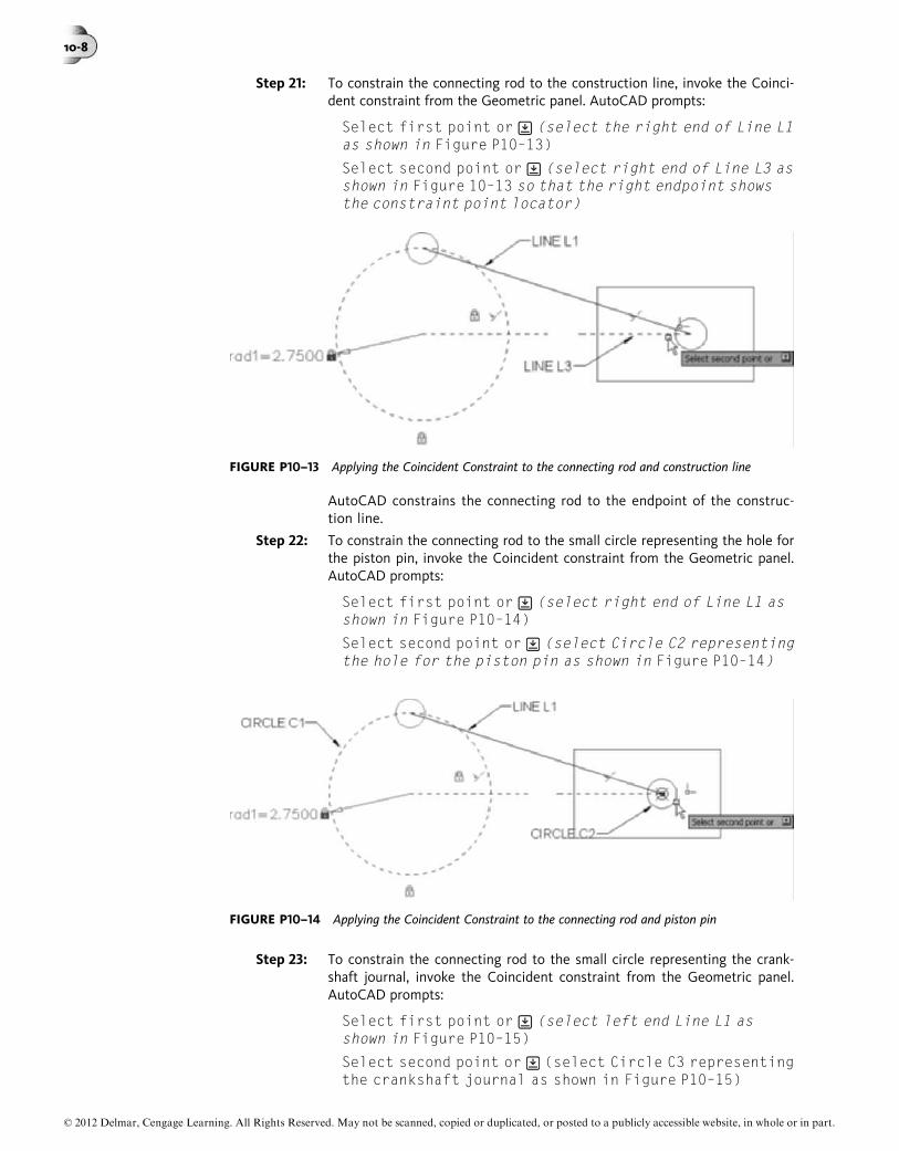
Step 21: To constrain the connecting rod to the construction line, invoke the Coinci-dent constraint from the Geometric panel. AutoCAD prompts:
Select first point or (select the right end of Line L1as shown in Figure P10–13)
Select second point or (select right end of Line L3 asshown in Figure 10–13 so that the right endpoint showsthe constraint point locator)
AutoCAD constrains the connecting rod to the endpoint of the construc-tion line.
Step 22: To constrain the connecting rod to the small circle representing the hole forthe piston pin, invoke the Coincident constraint from the Geometric panel.AutoCAD prompts:
Select first point or (select right end of Line L1 asshown in Figure P10–14)
Select second point or (select Circle C2 representingthe hole for the piston pin as shown in Figure P10–14)
Step 23: To constrain the connecting rod to the small circle representing the crank-shaft journal, invoke the Coincident constraint from the Geometric panel.AutoCAD prompts:
Select first point or (select left end Line L1 asshown in Figure P10–15)
Select second point or (select Circle C3 representingthe crankshaft journal as shown in Figure P10–15)
FIGURE P10–13 Applying the Coincident Constraint to the connecting rod and construction line
FIGURE P10–14 Applying the Coincident Constraint to the connecting rod and piston pin
© 2012 Delmar, Cengage Learning. All Rights Reserved. May not be scanned, copied or duplicated, or posted to a publicly accessible website, in whole or in part.
10-8

AutoCAD constrains the endpoint of the line to the center of the circle.
To constrain one of the corners of the piston, invoke the Coincidentconstraint from the Geometric panel. AutoCAD prompts:
Select first point or (select Line L4 toward thebottom outlining the piston as shown in Figure 10–16A)
Select second point or (select Line L5 toward the leftoutlining the piston as shown in Figure P10–16B)
FIGURE P10–16 Applying the Coincident Constraint to endpoints of two lines
FIGURE P10–15 Applying the Coincident Constraint to the connecting rod and crankshaft
© 2012 Delmar, Cengage Learning. All Rights Reserved. May not be scanned, copied or duplicated, or posted to a publicly accessible website, in whole or in part.
Chap t e r 10 • Pa rame t r i c Draw ing U s i n g Con s t r a i n t s 10-9

AutoCAD constrains the endpoint of the first selected line to the endpoint ofthe second selected line.
Step 24: Repeat the above step for the other three corners of the rectangle until thetwo lines at all four corners are constrained where they meet (Figure P10–17).
Step 25: Apply the Horizontal constraint from one end of the piston to one end ofthe connecting rod. Invoke the Horizontal Dimensional constraint from theDimensional panel (see Figure P10–18).
AutoCAD prompts:
Select first constraint point or (select Line L4towards the bottom outlining the piston as shown inFigure P10–19A)
Select second constraint point or (select the rightend of Line L1 as shown in Figure P10–19B)
Specify dimension line location: (specify a point todraw the dimension line as shown in Figure P10–20. Donot edit text)
FIGURE P10–17 Applying the Coincident Constraint to all four corners of piston
FIGURE P10–18 Invoking the Horizontal Dimensional Constraint from the Dimensional panel
© 2012 Delmar, Cengage Learning. All Rights Reserved. May not be scanned, copied or duplicated, or posted to a publicly accessible website, in whole or in part.
10-10

Step 26: Invoke the Vertical constraint and select Line L4 (Figure P10–21A). Invoke theVertical constraint again and select Line L6 (Figure P10–21B).
FIGURE P10–19 Applying the Horizontal Dimensional Constraint to the lower left corner of therectangle and the end of the connecting rod
FIGURE P10–20 Result of applying the Horizontal Dimensional Constraint
© 2012 Delmar, Cengage Learning. All Rights Reserved. May not be scanned, copied or duplicated, or posted to a publicly accessible website, in whole or in part.
Chap t e r 10 • Pa rame t r i c Draw ing U s i n g Con s t r a i n t s 10-11

Step 27: Invoke the Horizontal constraint and select Line L5. Invoke the Horizontalconstraint again and select Line L7.
Step 28: Invoke the Aligned Dimensional constraint from Dimensional panel.AutoCAD prompts:
Select first constraint point or (select Objectoption from the shortcut menu)
Select object:(select Line L1 as shown in Figure P10–22)
Specify dimension line location: (specify a point todraw the dimension line and change the text to a value of9.000 as shown in Figure P10–22)
You should note a change in the location of the piston when the dimension ischanged, making the new dimension the value of the constraint.
FIGURE P10–21 Applying the Vertical Constraint to the vertical lines of the piston
FIGURE P10–22 Applying the Aligned Dimensional Constraint to the connecting rod
© 2012 Delmar, Cengage Learning. All Rights Reserved. May not be scanned, copied or duplicated, or posted to a publicly accessible website, in whole or in part.
10-12

The drawing is now complete and the next step will demonstrate the effects ofthe constraints that were applied. By moving the grip at the crankshaft endof the connecting rod, the piston moves in a horizontal direction, simulatingthe actions of a reciprocating engine’s piston, rod, and crankshaft.
Step 29: Select the connecting rod so the grips will appear. Hold down the Pick buttonand move that end of the connecting rod away from its original position.Watch as the piston moves. Because the end of the connecting rod is con-strained to the large circle, it cannot be moved off of the circle.
Step 30: After moving the grip on the crankshaft end of the connecting rod counter-clockwise around the circle, the piston moves horizontally, maintaining thelength specified for the connecting rod (Figure P10–23). A clockwise movewill move the piston to the right (Figure P10–24).
FIGURE P10–23 Moving the grip on the connecting rod counterclockwise
FIGURE P10–24 Piston moves to the right as a result of moving the grip clockwise
© 2012 Delmar, Cengage Learning. All Rights Reserved. May not be scanned, copied or duplicated, or posted to a publicly accessible website, in whole or in part.
Chap t e r 10 • Pa rame t r i c Draw ing U s i n g Con s t r a i n t s 10-13

EXERCISE 10–1
The purpose of this exercise is to have four lines maintain their positions relative to eachother when one of the corner points is moved, without using the PLINE command ormaking them into a Block.
Draw a series of four lines (A, B, C, and D) to form a rectangle starting at 0,0, to 0,4, to7,0, to 7,0, and close to 0,0 (Figure Ex10–1-1).
Apply the Coincident constraint to each of the four corners to tie the adjoining lines.Apply the Horizontal constraint to Lines B and D. Apply the Vertical constraint toLines A and C.
After the constraints have been applied, select Line C so that grips are displayed. Movethe grip (Figure Ex10–1-2).
When one corner is moved, all of the lines maintain their positions relative to eachother.
FIGURE EX10–1-1 Rectangle created from four separate lines with constraints applied
FIGURE EX10–1-2 Moving the grip at the upper right corner
© 2012 Delmar, Cengage Learning. All Rights Reserved. May not be scanned, copied or duplicated, or posted to a publicly accessible website, in whole or in part.
10-14

EXERCISE 10–2
The purpose of this exercise is to constrain the center of a circle to the center of an arcand then an endpoint of the arc to the endpoint of a line so that when the line is movedto widen the bracket, the arc follows the line and the circle stays centered.
Set up the drawing with the Limits set at –3,–1.5 and 11,8. Set the Grid and Snap to 0.5with the Snap set to ON. Draw the Angle Bracket using five lines (A, B, C, D and E), ArcA, and Circle C, as shown in Figure Ex10–2-1.
Apply the Fix constraint to Line C at its upper end (3,6). Apply the Coincident constraintto Lines C and D where they meet (3,3). Apply the Coincident constraint to Line D andArc A where they meet (7.5,3). Apply the Concentric constraint to Arc A and Circle C.Apply the Fix constraint to the lower endpoint of Arc A (7.5,0). Constraint icons areshown in Figure Ex10–2-2.
Line D is selected so that the grips are displayed. Using the midpoint grip, move Line Dupward 1.0 units (Figure Ex10–2-3).
FIGURE EX10–2-1 Angle bracket with five lines, an arc, and a circle
FIGURE EX10–2-2 Angle bracket with constraint icons displayed
© 2012 Delmar, Cengage Learning. All Rights Reserved. May not be scanned, copied or duplicated, or posted to a publicly accessible website, in whole or in part.
Chap t e r 10 • Pa rame t r i c Draw ing U s i n g Con s t r a i n t s 10-15

After Line D is moved, Line C is shortened, Arc A is lengthened, and Circle C remains atthe center of the horizontal arm of the bracket (Figure Ex10–2-4).
FIGURE EX10–2-3 Moving the grip at the upper right corner
FIGURE EX10–2-4 Result of moving Line D upward 1.0 unit
© 2012 Delmar, Cengage Learning. All Rights Reserved. May not be scanned, copied or duplicated, or posted to a publicly accessible website, in whole or in part.
10-16

EXERCISE 10–3
The purpose of this exercise is to have the same constraints as Exercise 10–2 and alsohave the circle maintain a diameter that is 1.0 unit less than the width of the lowerbracket arm and diameter of the arc.
Start with the drawing that Exercise 10–2 started with, as shown in Figure Ex10–3-1, withthe constraints added (see Figure Ex10–2-2).
Apply the Vertical Dimensional constraint to Arc A, which is the same width as the lowerarm of the bracket, as shown in Figure Ex10–3-2.
Apply a Radius Dimensional constraint to Arc A and override the default with an equa-tion that makes it 1/2 of d1. Apply a Diameter dimensional constraint to Circle C andoverride the default with an equation that makes it 1.0 less than d1 (Figure Ex10–3-3).
FIGURE EX10–3-1 Angle bracket with five lines, an arc, and a circle with added constraints
FIGURE EX10–3-2 Angle bracket with Vertical Dimensional Constraint applied to Arc A
© 2012 Delmar, Cengage Learning. All Rights Reserved. May not be scanned, copied or duplicated, or posted to a publicly accessible website, in whole or in part.
Chap t e r 10 • Pa rame t r i c Draw ing U s i n g Con s t r a i n t s 10-17
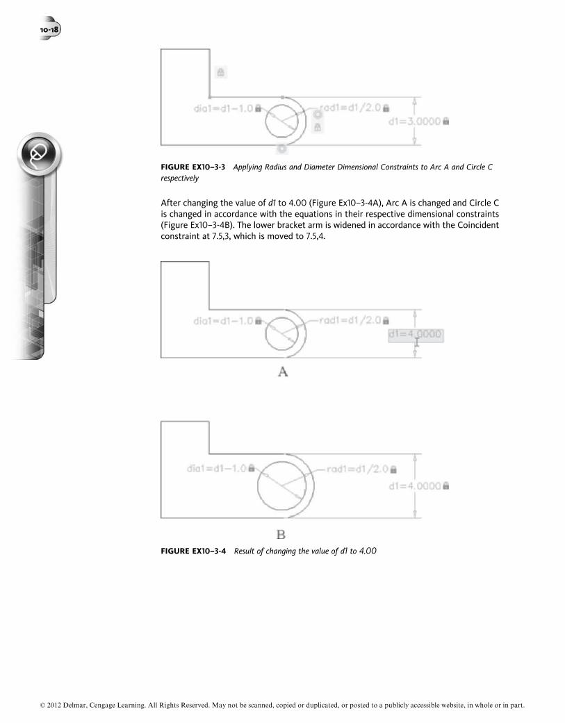
After changing the value of d1 to 4.00 (Figure Ex10–3-4A), Arc A is changed and Circle Cis changed in accordance with the equations in their respective dimensional constraints(Figure Ex10–3-4B). The lower bracket arm is widened in accordance with the Coincidentconstraint at 7.5,3, which is moved to 7.5,4.
FIGURE EX10–3-3 Applying Radius and Diameter Dimensional Constraints to Arc A and Circle Crespectively
FIGURE EX10–3-4 Result of changing the value of d1 to 4.00
© 2012 Delmar, Cengage Learning. All Rights Reserved. May not be scanned, copied or duplicated, or posted to a publicly accessible website, in whole or in part.
10-18