Ch10 Solutionsk
99
Chapter 10 External Flow: Drag and Lift Solutions Manual for Essentials of Fluid Mechanics: Fundamentals and Applications by Cimbala & Çengel CHAPTER 10 EXTERNAL FLOW: DRAG AND LIFT PROPRIETARY AND CONFIDENTIAL This Manual is the proprietary property of The McGraw-Hill Companies, Inc. (“McGraw-Hill”) and protected by copyright and other state and federal laws. By opening and using this Manual the user agrees to the following restrictions, and if the recipient does not agree to these restrictions, the Manual should be promptly returned unopened to McGraw- PROPRIETARY MATERIAL . © 2008 The McGraw-Hill Companies, Inc. Limited distribution permitted only to teachers and educators for course preparation. If you are a student using this Manual, you are using it without permission. 10-1
-
Upload
tensay-fekede -
Category
Documents
-
view
61 -
download
2
description
solution
Transcript of Ch10 Solutionsk
Chapter 10 External Flow: Drag and Lift
Solutions Manual for
Essentials of Fluid Mechanics:
Fundamentals and Applications
by Cimbala & Çengel
CHAPTER 10EXTERNAL FLOW: DRAG AND LIFT
PROPRIETARY AND CONFIDENTIAL
This Manual is the proprietary property of The McGraw-Hill Companies, Inc. (“McGraw-Hill”) and protected by copyright and other state and federal laws. By opening and using this Manual the user agrees to the following restrictions, and if the recipient does not agree to these restrictions, the Manual should be promptly returned unopened to McGraw-Hill: This Manual is being provided only to authorized professors and instructors for use in preparing for the classes using the affiliated textbook. No other use or distribution of this Manual is permitted. This Manual may not be sold and may not be distributed to or used by any student or other third party. No part of this Manual may be reproduced, displayed or distributed in any form or by any means, electronic or otherwise, without the prior written permission of McGraw-Hill.
PROPRIETARY MATERIAL. © 2008 The McGraw-Hill Companies, Inc. Limited distribution permitted only to teachers and educators for course preparation. If you are a student using this Manual, you are using it without permission.
10-1
Chapter 10 External Flow: Drag and Lift
Drag, Lift, and Drag Coefficients of Common Geometries
10-1C Solution We are to explain when a flow is 2-D, 3-D, and axisymmetric.
Analysis The flow over a body is said to be two-dimensional when the body is very long and of constant cross-section, and the flow is normal to the body (such as the wind blowing over a long pipe perpendicular to its axis). There is no significant flow along the axis of the body. The flow along a body that possesses symmetry along an axis in the flow direction is said to be axisymmetric (such as a bullet piercing through air). Flow over a body that cannot be modeled as two-dimensional or axisymmetric is three-dimensional. The flow over a car is three-dimensional.
Discussion As you might expect, 3-D flows are much more difficult to analyze than 2-D or axisymmetric flows.
10-2C Solution We are to discuss the difference between upstream and free-stream velocity.
Analysis The velocity of the fluid relative to the immersed solid body sufficiently far away from a body is called the free-stream velocity, V. The upstream (or approach) velocity V is the velocity of the approaching fluid far ahead of the body. These two velocities are equal if the flow is uniform and the body is small relative to the scale of the free-stream flow.
Discussion This is a subtle difference, and the two terms are often used interchangeably.
10-3C Solution We are to discuss the difference between streamlined and blunt bodies.
Analysis A body is said to be streamlined if a conscious effort is made to align its shape with the anticipated streamlines in the flow. Otherwise, a body tends to block the flow, and is said to be blunt. A tennis ball is a blunt body (unless the velocity is very low and we have “creeping flow”).
Discussion In creeping flow, the streamlines align themselves with the shape of any body – this is a much different regime than our normal experiences with flows in air and water. A low-drag body shape in creeping flow looks much different than a low-drag shape in high Reynolds number flow.
10-4C Solution We are to discuss applications in which a large drag is desired.
Analysis Some applications in which a large drag is desirable: parachuting, sailing, and the transport of pollens.
Discussion When sailing efficiently, however, the lift force on the sail is more important than the drag force in propelling the boat.
10-5C Solution We are to define drag and discuss why we usually try to minimize it.
Analysis The force a flowing fluid exerts on a body in the flow direction is called drag. Drag is caused by friction between the fluid and the solid surface, and the pressure difference between the front and back of the body . We try to minimize drag in order to reduce fuel consumption in vehicles, improve safety and durability of structures subjected to high winds, and to reduce noise and vibration.
Discussion In some applications, such as parachuting, high drag rather than low drag is desired.
PROPRIETARY MATERIAL. © 2008 The McGraw-Hill Companies, Inc. Limited distribution permitted only to teachers and educators for course preparation. If you are a student using this Manual, you are using it without permission.
10-2
Chapter 10 External Flow: Drag and Lift
10-6C Solution We are to define lift, and discuss its cause and the contribution of wall shear to lift.
Analysis The force a flowing fluid exerts on a body in the normal direction to flow that tends to move the body in that direction is called lift. It is caused by the components of the pressure and wall shear forces in the direction normal to the flow. The wall shear contributes to lift (unless the body is very slim), but its contribution is usually small.
Discussion Typically the nonsymmetrical shape of the body is what causes the lift force to be produced.
10-7C Solution We are to explain how to calculate the drag coefficient, and discuss the appropriate area.
Analysis When the drag force FD, the upstream velocity V, and the fluid density are measured during flow over a body, the drag coefficient is determined from
CD=F D
12
ρV 2 A
where A is ordinarily the frontal area (the area projected on a plane normal to the direction of flow) of the body.
Discussion In some cases, however, such as flat plates aligned with the flow or airplane wings, the planform area is used instead of the frontal area. Planform area is the area projected on a plane parallel to the direction of flow and normal to the lift force.
10-8C Solution We are to explain how to calculate the lift coefficient, and discuss the appropriate area.
Analysis When the lift force FL, the upstream velocity V, and the fluid density are measured during flow over a body, the lift coefficient can be determined from
CL=F L
12
ρV 2 A
where A is ordinarily the planform area, which is the area that would be seen by a person looking at the body from above in a direction normal to the body.
Discussion In some cases, however, such as flat plates aligned with the flow or airplane wings, the planform area is used instead of the frontal area. Planform area is the area projected on a plane parallel to the direction of flow and normal to the lift force.
10-9C Solution We are to define the frontal area of a body and discuss its applications.
Analysis The frontal area of a body is the area seen by a person when looking from upstream (the area projected on a plane normal to the direction of flow of the body). The frontal area is appropriate to use in drag and lift calculations for blunt bodies such as cars, cylinders, and spheres.
Discussion The drag force on a body is proportional to both the drag coefficient and the frontal area. Thus, one is able to reduce drag by reducing the drag coefficient or the frontal area (or both).
PROPRIETARY MATERIAL. © 2008 The McGraw-Hill Companies, Inc. Limited distribution permitted only to teachers and educators for course preparation. If you are a student using this Manual, you are using it without permission.
10-3
Chapter 10 External Flow: Drag and Lift
10-10C Solution We are to define the planform area of a body and discuss its applications.
Analysis The planform area of a body is the area that would be seen by a person looking at the body from above in a direction normal to flow. The planform area is the area projected on a plane parallel to the direction of flow and normal to the lift force. The planform area is appropriate to use in drag and lift calculations for slender bodies such as flat plate and airfoils when the frontal area is very small.
Discussion Consider for example an extremely thin flat plate aligned with the flow. The frontal area is nearly zero, and is therefore not appropriate to use for calculation of drag or lift coefficient.
10-11C Solution We are to define and discuss terminal velocity.
Analysis The maximum velocity a free falling body can attain is called the terminal velocity. It is determined by setting the weight of the body equal to the drag and buoyancy forces, W = FD + FB.
Discussion When discussing the settling of small dust particles, terminal velocity is also called terminal settling speed or settling velocity.
10-12C Solution We are to discuss the difference between skin friction drag and pressure drag, and which is more significant for slender bodies.
Analysis The part of drag that is due directly to wall shear stress w is called the skin friction drag FD, friction since it is caused by frictional effects, and the part that is due directly to pressure P and depends strongly on the shape of the body is called the pressure drag FD, pressure. For slender bodies such as airfoils, the friction drag is usually more significant.
Discussion For blunt bodies, on the other hand, pressure drag is usually more significant than skin friction drag.
10-13C Solution We are to discuss the effect of surface roughness on drag coefficient.
Analysis The friction drag coefficient is independent of surface roughness in laminar flow, but is a strong function of surface roughness in turbulent flow due to surface roughness elements protruding farther into the viscous sublayer.
Discussion If the roughness is very large, however, the drag on bodies is increased even for laminar flow, due to pressure effects on the roughness elements.
10-14C Solution We are to discuss how drag coefficient varies with Reynolds number.
Analysis (a) In general, the drag coefficient decreases with Reynolds number at low and moderate Reynolds numbers. (b) The drag coefficient is nearly independent of Reynolds number at high Reynolds numbers (Re > 104).
Discussion When the drag coefficient is independent of Re at high values of Re, we call this Reynolds number independence.
PROPRIETARY MATERIAL. © 2008 The McGraw-Hill Companies, Inc. Limited distribution permitted only to teachers and educators for course preparation. If you are a student using this Manual, you are using it without permission.
10-4
Chapter 10 External Flow: Drag and Lift
10-15C Solution We are to discuss the effect of adding a fairing to a circular cylinder.
Analysis As a result of attaching fairings to the front and back of a cylindrical body at high Reynolds numbers, (a) friction drag increases, (b) pressure drag decreases, and (c) total drag decreases.
Discussion In creeping flow (very low Reynolds numbers), however, adding a fairing like this would actually increase the overall drag, since the surface area and therefore the skin friction drag would increase significantly.
10-16C Solution We are to discuss the effect of streamlining, and its effect on friction drag and pressure drag.
Analysis As a result of streamlining, (a) friction drag increases, (b) pressure drag decreases, and (c) total drag decreases at high Reynolds numbers (the general case), but increases at very low Reynolds numbers (creeping flow) since the friction drag dominates at low Reynolds numbers.
Discussion Streamlining can significantly reduce the overall drag on a body at high Reynolds number.
10-17C Solution We are to define and discuss flow separation.
Analysis At sufficiently high velocities, the fluid stream detaches itself from the surface of the body. This is called separation. It is caused by a fluid flowing over a curved surface at a high velocity (or technically, by adverse pressure gradient). Separation increases the drag coefficient drastically.
Discussion A boundary layer has a hard time resisting an adverse pressure gradient, and is likely to separate. A turbulent boundary layer is in general more resilient to flow separation than a laminar flow.
10-18C Solution We are to define and discuss drafting.
Analysis Drafting is when a moving body follows another moving body by staying close behind in order to reduce drag. It reduces the pressure drag and thus the drag coefficient for the drafted body by taking advantage of the low pressure wake region of the moving body in front.
Discussion We often see drafting in automobile and bicycle racing.
10-19C Solution We are to compare the fuel efficiency of two cars.
Analysis The car that is contoured to resemble an ellipse has a smaller drag coefficient and thus smaller air resistance, and thus the elliptical car is more likely to be more fuel efficient than a car with sharp corners.
Discussion However, sharp corners promote a fixed flow separation location, whereas rounded corners can lead to unsteadiness in the flow. For this reason, rounding is usually, but not always the best solution.
10-20C Solution We are to compare the speed of two bicyclists.
Analysis The bicyclist who leans down and brings his body closer to his knees goes faster since the frontal area and thus the drag force is less in that position. The drag coefficient also goes down somewhat, but this is a secondary effect.
Discussion This is easily experienced when riding a bicycle down a long hill.
PROPRIETARY MATERIAL. © 2008 The McGraw-Hill Companies, Inc. Limited distribution permitted only to teachers and educators for course preparation. If you are a student using this Manual, you are using it without permission.
10-5
Wind tunnel90 km/h
FD
Wind80 km/h
FR=700 N
35
V
Chapter 10 External Flow: Drag and Lift
10-21
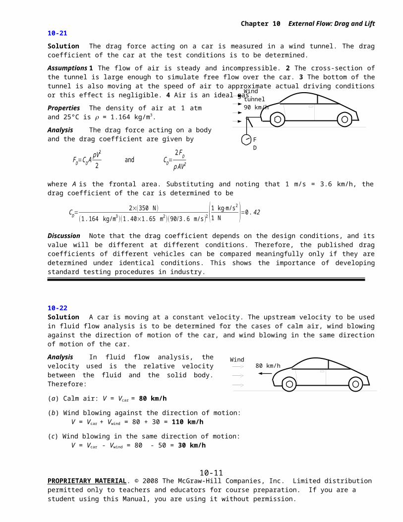
Solution The drag force acting on a car is measured in a wind tunnel. The drag coefficient of the car at the test conditions is to be determined.
Assumptions 1 The flow of air is steady and incompressible. 2 The cross-section of the tunnel is large enough to simulate free flow over the car. 3 The bottom of the tunnel is also moving at the speed of air to approximate actual driving conditions or this effect is negligible. 4 Air is an ideal gas.
Properties The density of air at 1 atm and 25°C is = 1.164 kg/m3.
Analysis The drag force acting on a body and the drag coefficient are given by
FD=CD AρV 2
2 and C D=
2FD
ρ AV 2
where A is the frontal area. Substituting and noting that 1 m/s = 3.6 km/h, the drag coefficient of the car is determined to be
CD=2×(350 N)
(1. 164 kg/m3 )(1 . 40×1 . 65 m2 )(90 /3 . 6 m/s)2 (1 kg⋅m/s2
1 N )=0 . 42
Discussion Note that the drag coefficient depends on the design conditions, and its value will be different at different conditions. Therefore, the published drag coefficients of different vehicles can be compared meaningfully only if they are determined under identical conditions. This shows the importance of developing standard testing procedures in industry.
10-22 Solution A car is moving at a constant velocity. The upstream velocity to be used in fluid flow analysis is to be determined for the cases of calm air, wind blowing against the direction of motion of the car, and wind blowing in the same direction of motion of the car.
Analysis In fluid flow analysis, the velocity used is the relative velocity between the fluid and the solid body. Therefore:
(a) Calm air: V = Vcar = 80 km/h
(b) Wind blowing against the direction of motion: V = Vcar + Vwind = 80 + 30 = 110 km/h
(c) Wind blowing in the same direction of motion: V = Vcar - Vwind = 80 - 50 = 30 km/h
Discussion Note that the wind and car velocities are added when they are in opposite directions, and subtracted when they are in the same direction.
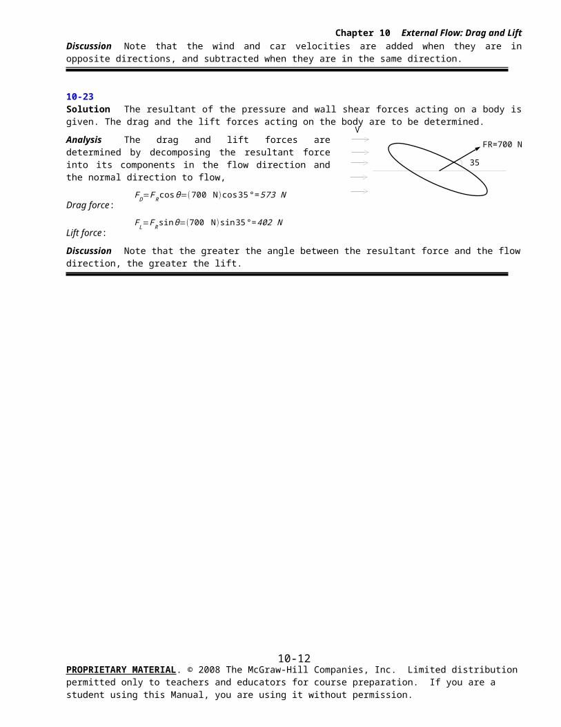
10-23 Solution The resultant of the pressure and wall shear forces acting on a body is given. The drag and the lift forces acting on the body are to be determined.
Analysis The drag and lift forces are determined by decomposing the resultant force into its components in the flow direction and the normal direction to flow,
Drag force:FD=FR cosθ=(700 N )cos35°=573 N
Lift force:FL=F Rsin θ=(700 N)sin 35 °= 402 N
PROPRIETARY MATERIAL. © 2008 The McGraw-Hill Companies, Inc. Limited distribution permitted only to teachers and educators for course preparation. If you are a student using this Manual, you are using it without permission.
10-6
Chapter 10 External Flow: Drag and Lift
Discussion Note that the greater the angle between the resultant force and the flow direction, the greater the lift.
PROPRIETARY MATERIAL. © 2008 The McGraw-Hill Companies, Inc. Limited distribution permitted only to teachers and educators for course preparation. If you are a student using this Manual, you are using it without permission.
10-7
AirV
D = 12 cm
Chapter 10 External Flow: Drag and Lift
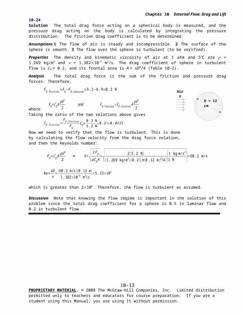
10-24 Solution The total drag force acting on a spherical body is measured, and the pressure drag acting on the body is calculated by integrating the pressure distribution. The friction drag coefficient is to be determined.
Assumptions 1 The flow of air is steady and incompressible. 2 The surface of the sphere is smooth. 3 The flow over the sphere is turbulent (to be verified).
Properties The density and kinematic viscosity of air at 1 atm and 5C are = 1.269 kg/m3 and = 1.38210-5 m2/s. The drag coefficient of sphere in turbulent flow is CD = 0.2, and its frontal area is A = D2/4 (Table 10-2).
Analysis The total drag force is the sum of the friction and pressure drag forces. Therefore,
FD , friction=FD−F D , pressure=5 .2−4 .9=0 . 3 N
where FD=CD A
ρV 2
2 and F D, friction=CD , friction A
ρV2
2
Taking the ratio of the two relations above gives
CD , friction=F D, friction
FD
CD=0 .3 N5 .2 N
(0 .2)=0 .0115
Now we need to verify that the flow is turbulent. This is done by calculating the flow velocity from the drag force relation, and then the Reynolds number:
FD=CD AρV 2
2 → V=√ 2 FD
ρC D A=√ 2(5 .2 N )
(1 . 269 kg/m3 )(0 . 2)[ π (0. 12 m )2/ 4 ] (1 kg⋅m/s2
1 N )=60 .2 m/s
Re=VDν
=(60 . 2 m/s)(0 . 12 m )
1. 382×10-5 m2 /s=5 . 23×105
which is greater than 2105. Therefore, the flow is turbulent as assumed.
Discussion Note that knowing the flow regime is important in the solution of this problem since the total drag coefficient for a sphere is 0.5 in laminar flow and 0.2 in turbulent flow.
PROPRIETARY MATERIAL. © 2008 The McGraw-Hill Companies, Inc. Limited distribution permitted only to teachers and educators for course preparation. If you are a student using this Manual, you are using it without permission.
10-8
Chapter 10 External Flow: Drag and Lift
10-25E Solution The frontal area of a car is reduced by redesigning. The amount of fuel and money saved per year as a result are to be determined.
Assumptions 1 The car is driven 12,000 miles a year at an average speed of 55 km/h. 2 The effect of reduction of the frontal area on the drag coefficient is negligible.
Properties The densities of air and gasoline are given to be 0.075 lbm/ft3
and 50 lbm/ft3, respectively. The heating value of gasoline is given to be 20,000 Btu/lbm. The drag coefficient is CD = 0.3 for a passenger car (Table 10-2).
Analysis The drag force acting on a body is determined from
FD=CD AρV 2
2where A is the frontal area of the body. The drag force acting on the car before redesigning is
FD=0 .3 (18 ft2)(0 .075 lbm/ft3 )(55 mph )2
2 ( 1.4667 ft/s1 mph )
2
( 1 lbf32 .2 lbm⋅ft/s2 )=40 .9 lbf
Noting that work is force times distance, the amount of work done to overcome this drag force and the required energy input for a distance of 12,000 miles are
W drag=FD L=(40 . 9 lbf )(12,000 miles/year )(5280 ft1 mile )(1 Btu
778 .169 lbf⋅ft )=3. 33×106 Btu/year
Ein=W drag
ηcar
=3. 33×106 Btu/year0. 32
=1 .041×107 Btu/year
Then the amount and costs of the fuel that supplies this much energy are
Amont of fuel=mfuel
ρ fuel
=E in /HV
ρfuel
=(1 .041×107 Btu/year )/(20 ,000 Btu/lbm )50 lbm/ft3
=10 . 41 ft3 /year
Cost=(Amount of fuel)(Unit cost )=(10 . 41 ft3 /year )($2. 20/gal )( 7 . 4804 gal
1 ft3 )=$171 .3/year
That is, the car uses 10.41 ft3 = 77.9 gallons of gasoline at a cost of $171.3 per year to overcome the drag. The drag force and the work done to overcome it are directly proportional to the frontal area. Then the percent
reduction in the fuel consumption due to reducing frontal area is equal to the percent reduction in the frontal area:
Reduction ratio=A−Anew
A=18−15
18=0.167
Amount reduction=(Reduction ratio )(Amount )¿0 .167(77 .9 gal/year)=13 .0 gal/yearCost reduction=(Reduction ratio)(Cost )=0 .167($171 .3/year )=$28 .6/year
Therefore, reducing the frontal area reduces the fuel consumption due to drag by 16.7%.
Discussion Note from this example that significant reductions in drag and fuel consumption can be achieved by reducing the frontal area of a vehicle.
PROPRIETARY MATERIAL. © 2008 The McGraw-Hill Companies, Inc. Limited distribution permitted only to teachers and educators for course preparation. If you are a student using this Manual, you are using it without permission.
10-9
Chapter 10 External Flow: Drag and Lift
10-26E
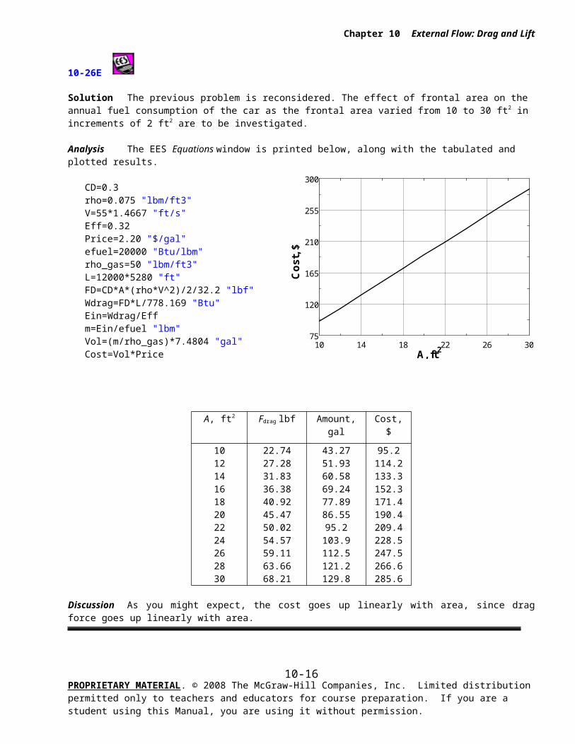
Solution The previous problem is reconsidered. The effect of frontal area on the annual fuel consumption of the car as the frontal area varied from 10 to 30 ft2 in increments of 2 ft2 are to be investigated.
Analysis The EES Equations window is printed below, along with the tabulated and plotted results.
CD=0.3rho=0.075 "lbm/ft3"V=55*1.4667 "ft/s"Eff=0.32Price=2.20 "$/gal"efuel=20000 "Btu/lbm"rho_gas=50 "lbm/ft3"L=12000*5280 "ft"FD=CD*A*(rho*V^2)/2/32.2 "lbf"Wdrag=FD*L/778.169 "Btu"Ein=Wdrag/Effm=Ein/efuel "lbm"Vol=(m/rho_gas)*7.4804 "gal"Cost=Vol*Price
A, ft2 Fdrag lbf Amount, gal Cost, $
1012141618202224262830
22.7427.2831.8336.3840.9245.4750.0254.5759.1163.6668.21
43.2751.9360.5869.2477.8986.5595.2103.9112.5121.2129.8
95.2114.2133.3152.3171.4190.4209.4228.5247.5266.6285.6
Discussion As you might expect, the cost goes up linearly with area, since drag force goes up linearly with area.
PROPRIETARY MATERIAL. © 2008 The McGraw-Hill Companies, Inc. Limited distribution permitted only to teachers and educators for course preparation. If you are a student using this Manual, you are using it without permission.
10 14 18 22 26 3075
120
165
210
255
300
A, ft2
Co
st,
$
10-10
1.5 m
150 km/h50 cm
SIGN
90 mph
20 ft
8 ftBILLBOARD
Chapter 10 External Flow: Drag and Lift
10-27 [Also solved using EES on enclosed DVD]
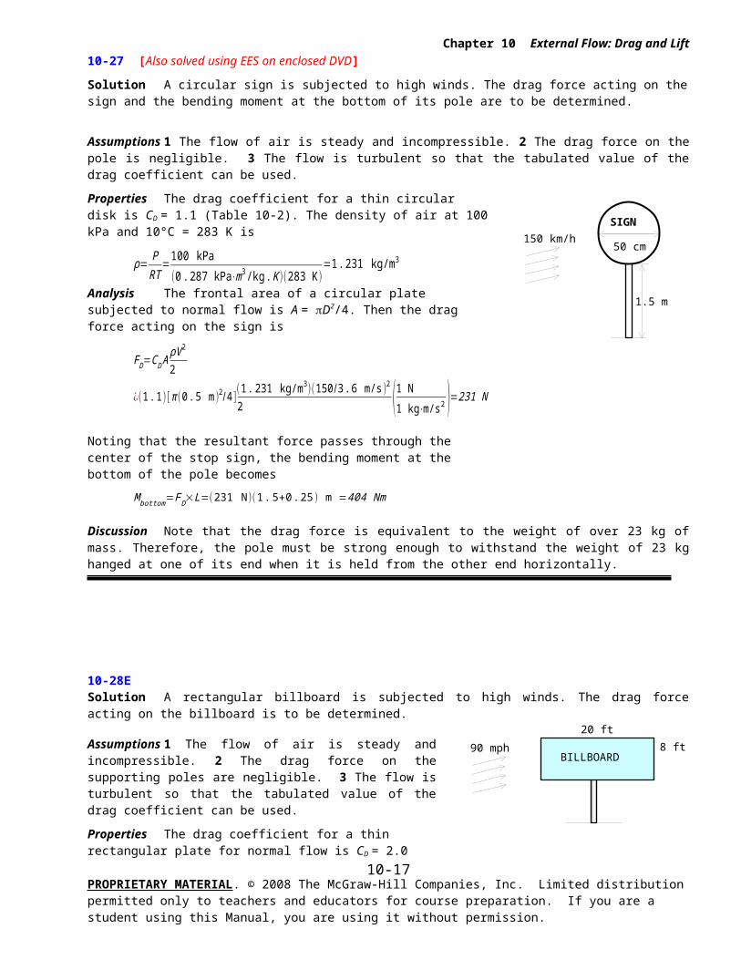
Solution A circular sign is subjected to high winds. The drag force acting on the sign and the bending moment at the bottom of its pole are to be determined.
Assumptions 1 The flow of air is steady and incompressible. 2 The drag force on the pole is negligible. 3 The flow is turbulent so that the tabulated value of the drag coefficient can be used.
Properties The drag coefficient for a thin circular disk is CD = 1.1 (Table 10-2). The density of air at 100 kPa and 10°C = 283 K is
ρ= PRT
=100 kPa
( 0. 287 kPa⋅m3 /kg. K )(283 K )=1. 231 kg/m3
Analysis The frontal area of a circular plate subjected to normal flow is A = D2/4. Then the drag force acting on the sign is
FD=CD AρV 2
2
¿(1 . 1)[ π (0 .5 m )2/ 4 ](1 .231 kg/m3 )(150/3 . 6 m/s )2
2 (1 N1 kg⋅m/s2 )=231 N
Noting that the resultant force passes through the center of the stop sign, the bending moment at the bottom of the pole becomes
M bottom=FD×L=(231 N)(1 .5+0 .25 ) m =404 Nm
Discussion Note that the drag force is equivalent to the weight of over 23 kg of mass. Therefore, the pole must be strong enough to withstand the weight of 23 kg hanged at one of its end when it is held from the other end horizontally.
10-28E Solution A rectangular billboard is subjected to high winds. The drag force acting on the billboard is to be determined.
Assumptions 1 The flow of air is steady and incompressible. 2 The drag force on the supporting poles are negligible. 3 The flow is turbulent so that the tabulated value of the drag coefficient can be used.
Properties The drag coefficient for a thin rectangular plate for normal flow is CD = 2.0 (Table 10-2). The density of air at 14.3 psia and 40°F = 500 R is
ρ= PRT
=14 .3 psia
( 0. 3704 psia⋅ft3 /lbm .R )(500 R )=0 .0772 lbm/ft3
Analysis The drag force acting on the billboard is determined from
Discussion Note that the drag force is equivalent to the weight of about 6680 lbm of mass. Therefore, the support bars must be strong enough to withstand the weight of 6680 lbm hanged at one of their ends when they are held from the other end horizontally.
PROPRIETARY MATERIAL. © 2008 The McGraw-Hill Companies, Inc. Limited distribution permitted only to teachers and educators for course preparation. If you are a student using this Manual, you are using it without permission.
10-11
TAXI
AD
Chapter 10 External Flow: Drag and Lift
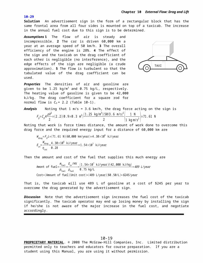
10-29 Solution An advertisement sign in the form of a rectangular block that has the same frontal area from all four sides is mounted on top of a taxicab. The increase in the annual fuel cost due to this sign is to be determined.
Assumptions 1 The flow of air is steady and incompressible. 2 The car is driven 60,000 km a year at an average speed of 50 km/h. 3 The overall efficiency of the engine is 28%. 4 The effect of the sign and the taxicab on the drag coefficient of each other is negligible (no interference), and the edge effects of the sign are negligible (a crude approximation). 5 The flow is turbulent so that the tabulated value of the drag coefficient can be used.
Properties The densities of air and gasoline are given to be 1.25 kg/m3
and 0.75 kg/L, respectively. The heating value of gasoline is given to be 42,000 kJ/kg. The drag coefficient for a square rod for normal flow is CD = 2.2 (Table 10-1).
Analysis Noting that 1 m/s = 3.6 km/h, the drag force acting on the sign is
FD=CD AρV 2
2=(2 .2 )(0 .9×0 .3 m2 )
(1 . 25 kg/m3 )(50 /3. 6 m/s )2
2 ( 1 N1 kg⋅m/s2 )=71.61 N
Noting that work is force times distance, the amount of work done to overcome this drag force and the required energy input for a distance of 60,000 km are
W drag=FD L=(71.61 N )(60,000 km/year )=4 . 30×106 kJ/year
Ein=W drag
ηcar
=4 .30×106 kJ/year0. 28
=1 .54×107 kJ/year
Then the amount and cost of the fuel that supplies this much energy are
Amont of fuel=mfuel
ρ fuel
=Ein /HV
ρfuel
=(1 .54×107 kJ/year )/( 42 ,000 kJ/kg )0 .75 kg/L
=489 L/year
Cost=(Amount of fuel)(Unit cost )=(489 L/year )($0 .50/L )=$245/year
That is, the taxicab will use 489 L of gasoline at a cost of $245 per year to overcome the drag generated by the advertisement sign.
Discussion Note that the advertisement sign increases the fuel cost of the taxicab significantly. The taxicab operator may end up losing money by installing the sign if he/she is not aware of the major increase in the fuel cost, and negotiate accordingly.
PROPRIETARY MATERIAL. © 2008 The McGraw-Hill Companies, Inc. Limited distribution permitted only to teachers and educators for course preparation. If you are a student using this Manual, you are using it without permission.
10-12
RV
2 m
0.5 m
Chapter 10 External Flow: Drag and Lift
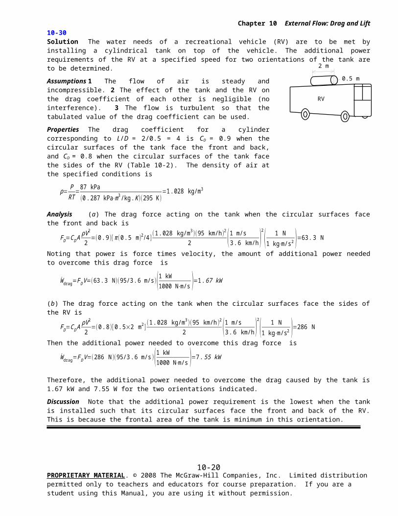
10-30 Solution The water needs of a recreational vehicle (RV) are to be met by installing a cylindrical tank on top of the vehicle. The additional power requirements of the RV at a specified speed for two orientations of the tank are to be determined.
Assumptions 1 The flow of air is steady and incompressible. 2 The effect of the tank and the RV on the drag coefficient of each other is negligible (no interference). 3 The flow is turbulent so that the tabulated value of the drag coefficient can be used.
Properties The drag coefficient for a cylinder corresponding to L/D = 2/0.5 = 4 is CD = 0.9 when the circular surfaces of the tank face the front and back, and CD = 0.8 when the circular surfaces of the tank face the sides of the RV (Table 10-2). The density of air at the specified conditions is
ρ= PRT
=87 kPa
( 0. 287 kPa⋅m3 /kg. K )(295 K )=1. 028 kg/m3
Analysis (a) The drag force acting on the tank when the circular surfaces face the front and back is
FD=CD AρV 2
2=(0 . 9)[ π (0 .5 m)2 /4 ]
(1 .028 kg/m3)( 95 km/h )2
2 (1 m/s3 .6 km/h )
2
( 1 N1 kg⋅m/s2 )=63. 3 N
Noting that power is force times velocity, the amount of additional power needed to overcome this drag force is
W drag=FD V =(63 . 3 N )(95/3 . 6 m/s)(1 kW1000 N⋅m/s )=1. 67 kW
(b) The drag force acting on the tank when the circular surfaces face the sides of the RV is
FD=CD AρV 2
2=(0 . 8)[ 0 .5×2 m2 ]
(1 .028 kg/m3 )(95 km/h )2
2 (1 m/s3 . 6 km/h )
2
( 1 N1 kg⋅m/s2 )=286 N
Then the additional power needed to overcome this drag force is
W drag=FD V =(286 N)(95/3 .6 m/s )(1 kW1000 N⋅m/s )=7 . 55 kW
Therefore, the additional power needed to overcome the drag caused by the tank is 1.67 kW and 7.55 W for the two orientations indicated.
Discussion Note that the additional power requirement is the lowest when the tank is installed such that its circular surfaces face the front and back of the RV. This is because the frontal area of the tank is minimum in this orientation.
PROPRIETARY MATERIAL. © 2008 The McGraw-Hill Companies, Inc. Limited distribution permitted only to teachers and educators for course preparation. If you are a student using this Manual, you are using it without permission.
10-13
V
4 mm
Water
Chapter 10 External Flow: Drag and Lift
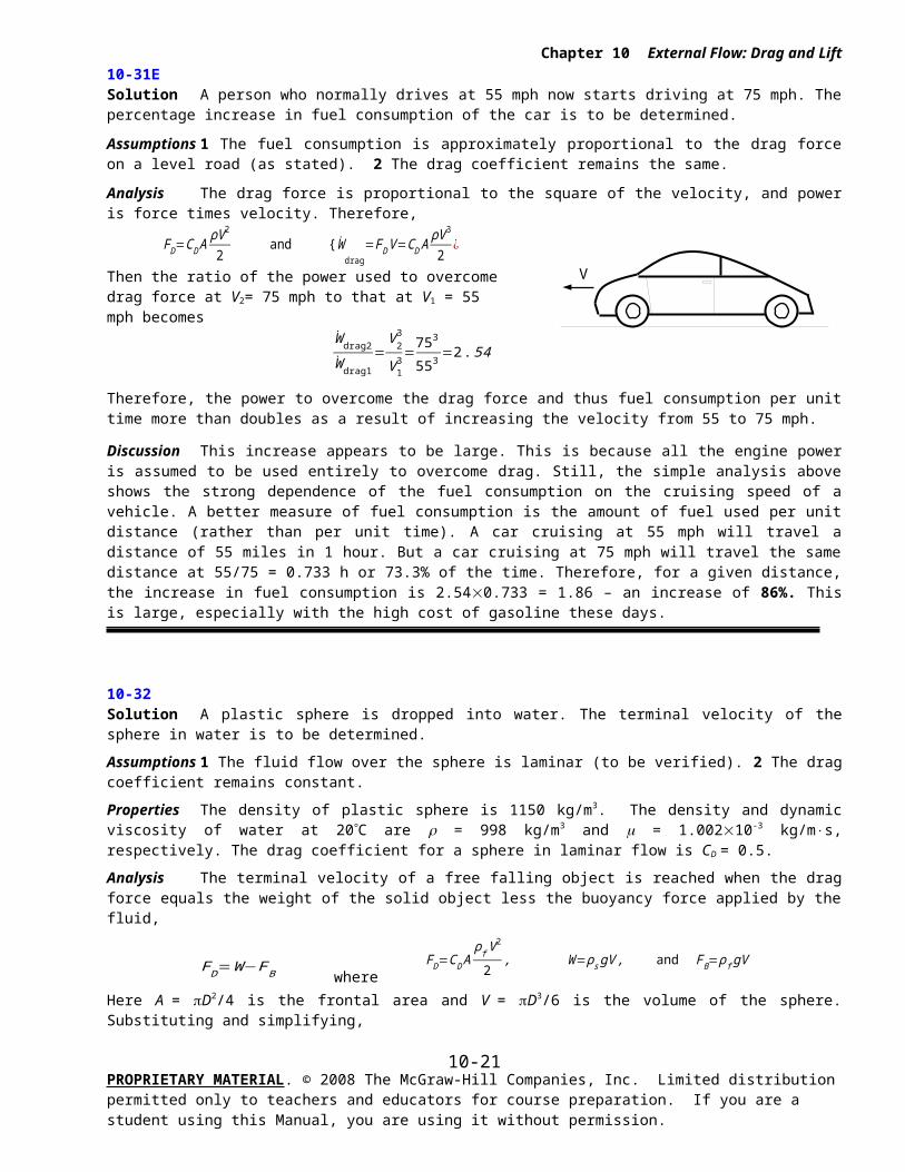
10-31E Solution A person who normally drives at 55 mph now starts driving at 75 mph. The percentage increase in fuel consumption of the car is to be determined.
Assumptions 1 The fuel consumption is approximately proportional to the drag force on a level road (as stated). 2 The drag coefficient remains the same.
Analysis The drag force is proportional to the square of the velocity, and power is force times velocity. Therefore,
FD=CD AρV 2
2 and {W
drag=FD V =CD A
ρV 3
2¿
Then the ratio of the power used to overcome drag force at V2= 75 mph to that at V1 = 55 mph becomes
W drag2
W drag1
=V 2
3
V 13=753
553=2. 54
Therefore, the power to overcome the drag force and thus fuel consumption per unit time more than doubles as a result of increasing the velocity from 55 to 75 mph.
Discussion This increase appears to be large. This is because all the engine power is assumed to be used entirely to overcome drag. Still, the simple analysis above shows the strong dependence of the fuel consumption on the cruising speed of a vehicle. A better measure of fuel consumption is the amount of fuel used per unit distance (rather than per unit time). A car cruising at 55 mph will travel a distance of 55 miles in 1 hour. But a car cruising at 75 mph will travel the same distance at 55/75 = 0.733 h or 73.3% of the time. Therefore, for a given distance, the increase in fuel consumption is 2.540.733 = 1.86 – an increase of 86%. This is large, especially with the high cost of gasoline these days.
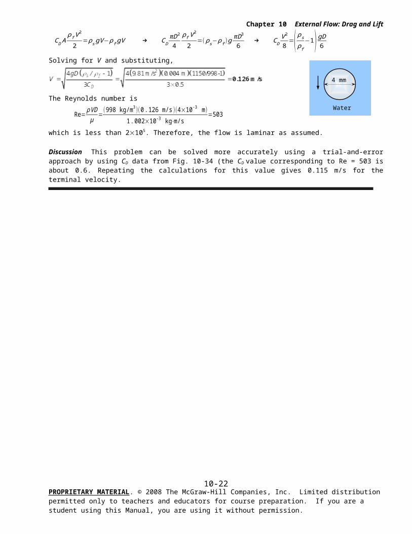
10-32 Solution A plastic sphere is dropped into water. The terminal velocity of the sphere in water is to be determined.
Assumptions 1 The fluid flow over the sphere is laminar (to be verified). 2 The drag coefficient remains constant.
Properties The density of plastic sphere is 1150 kg/m3. The density and dynamic viscosity of water at 20 C are = 998 kg/m3 and m = 1.00210-3 kg/m×s, respectively. The drag coefficient for a sphere in laminar flow is CD = 0.5.
Analysis The terminal velocity of a free falling object is reached when the drag force equals the weight of the solid object less the buoyancy force applied by the fluid,
FD=W−FB where FD=CD A
ρ f V 2
2, W=ρ s gV , and FB=ρf gV
Here A = D2/4 is the frontal area and V = D3/6 is the volume of the sphere. Substituting and simplifying,
CD Aρf V 2
2=ρ s gV −ρ f gV → C D
πD2
4
ρ f V 2
2=( ρ s− ρf )g
πD3
6 → CD
V 2
8=( ρ s
ρ f
−1) gD6
Solving for V and substituting,
The Reynolds number is
Re= ρVDμ
=(998 kg/m3 )(0.126 m/s )(4×10⁻³ m)
1. 002×10-3 kg⋅m/s=503
which is less than 2105. Therefore, the flow is laminar as assumed.
Discussion This problem can be solved more accurately using a trial-and-error approach by using CD data from Fig. 10-34 (the CD value corresponding to Re = 503 is about 0.6. Repeating the calculations for this value gives 0.115 m/s for the terminal velocity.
PROPRIETARY MATERIAL. © 2008 The McGraw-Hill Companies, Inc. Limited distribution permitted only to teachers and educators for course preparation. If you are a student using this Manual, you are using it without permission.
10-14
5,000 kg
8 m 1.8 m
2 m
0.75 m
V
Chapter 10 External Flow: Drag and Lift
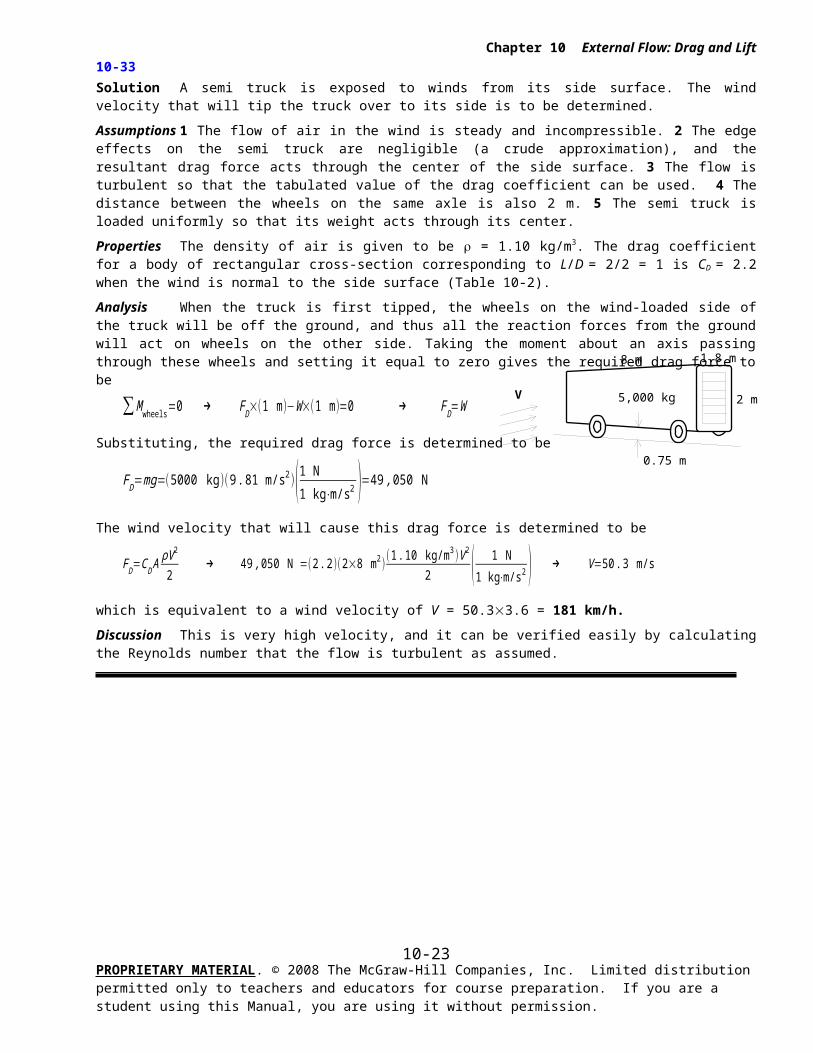
10-33 Solution A semi truck is exposed to winds from its side surface. The wind velocity that will tip the truck over to its side is to be determined.
Assumptions 1 The flow of air in the wind is steady and incompressible. 2 The edge effects on the semi truck are negligible (a crude approximation), and the resultant drag force acts through the center of the side surface. 3 The flow is turbulent so that the tabulated value of the drag coefficient can be used. 4 The distance between the wheels on the same axle is also 2 m. 5 The semi truck is loaded uniformly so that its weight acts through its center.
Properties The density of air is given to be = 1.10 kg/m3. The drag coefficient for a body of rectangular cross-section corresponding to L/D = 2/2 = 1 is CD = 2.2 when the wind is normal to the side surface (Table 10-2).
Analysis When the truck is first tipped, the wheels on the wind-loaded side of the truck will be off the ground, and thus all the reaction forces from the ground will act on wheels on the other side. Taking the moment about an axis passing through these wheels and setting it equal to zero gives the required drag force to be
∑M wheels=0 → FD×(1 m )−W×(1 m)=0 → F D=W
Substituting, the required drag force is determined to be
FD=mg=(5000 kg )(9 . 81 m/s2 )(1 N
1 kg⋅m/s2 )=49 ,050 N
The wind velocity that will cause this drag force is determined to be
FD=CD AρV 2
2 → 49 ,050 N =(2 .2 )(2×8 m2 )
(1 .10 kg/m3 )V 2
2 ( 1 N1 kg⋅m/s2 ) → V =50 .3 m/s
which is equivalent to a wind velocity of V = 50.33.6 = 181 km/h.
Discussion This is very high velocity, and it can be verified easily by calculating the Reynolds number that the flow is turbulent as assumed.
PROPRIETARY MATERIAL. © 2008 The McGraw-Hill Companies, Inc. Limited distribution permitted only to teachers and educators for course preparation. If you are a student using this Manual, you are using it without permission.
10-15
25 cm
Chapter 10 External Flow: Drag and Lift
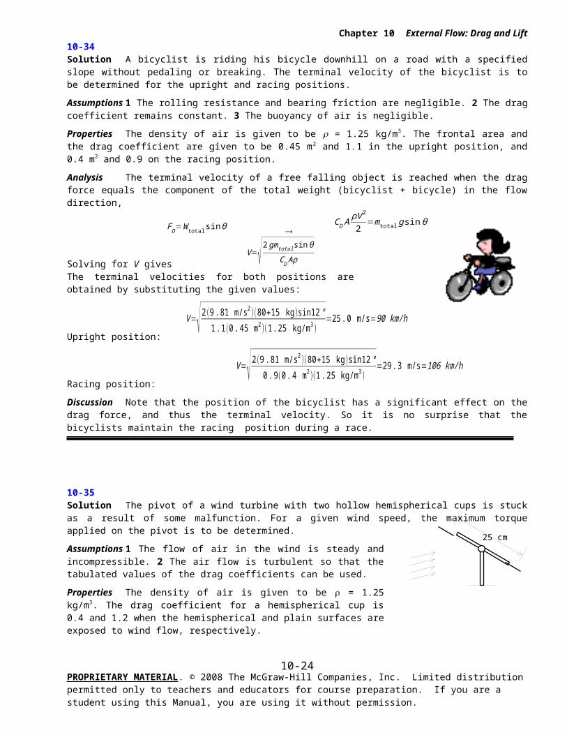
10-34 Solution A bicyclist is riding his bicycle downhill on a road with a specified slope without pedaling or breaking. The terminal velocity of the bicyclist is to be determined for the upright and racing positions.
Assumptions 1 The rolling resistance and bearing friction are negligible. 2 The drag coefficient remains constant. 3 The buoyancy of air is negligible.
Properties The density of air is given to be = 1.25 kg/m3. The frontal area and the drag coefficient are given to be 0.45 m2 and 1.1 in the upright position, and 0.4 m2 and 0.9 on the racing position.
Analysis The terminal velocity of a free falling object is reached when the drag force equals the component of the total weight (bicyclist + bicycle) in the flow direction,
FD=W total sinθ CD A
ρV 2
2=mtotal g sin θ
Solving for V gives V =√ 2 gmtotal sin θ
CD Aρ
The terminal velocities for both positions are obtained by substituting the given values:
Upright position:
V=√ 2(9 . 81 m/s2 )(80+15 kg )sin12°
1 . 1(0 .45 m2 )(1 .25 kg/m3 )=25 .0 m/s=90 km/h
Racing position:
V=√ 2(9 .81 m/s2 )(80+15 kg )sin12°
0 . 9(0 . 4 m2 )(1.25 kg/m3 )=29 .3 m/s=106 km/h
Discussion Note that the position of the bicyclist has a significant effect on the drag force, and thus the terminal velocity. So it is no surprise that the bicyclists maintain the racing position during a race.
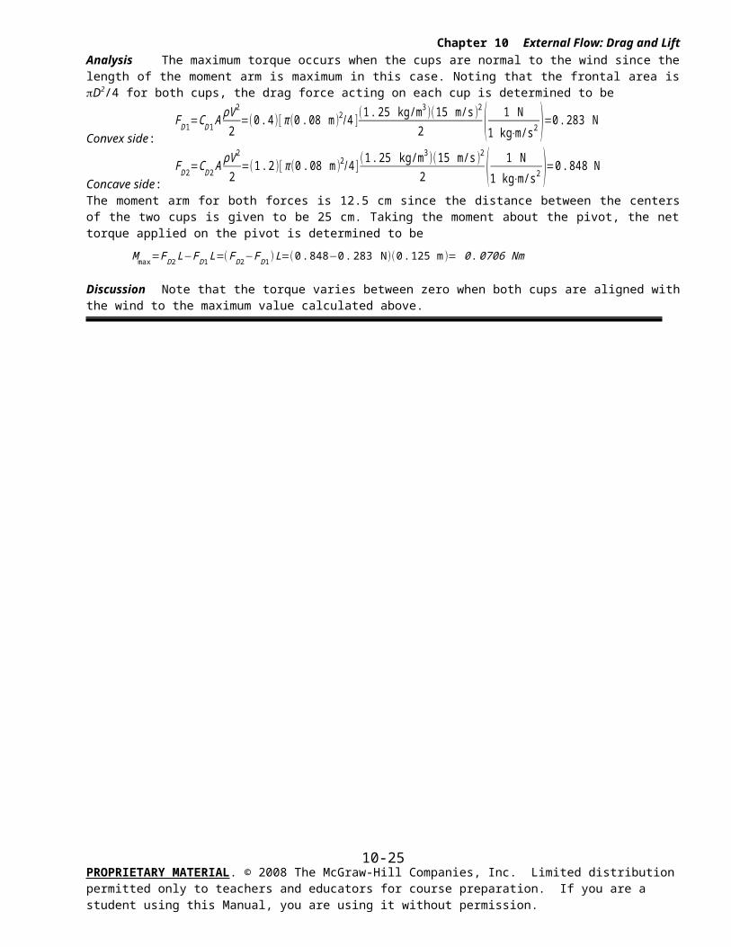
10-35 Solution The pivot of a wind turbine with two hollow hemispherical cups is stuck as a result of some malfunction. For a given wind speed, the maximum torque applied on the pivot is to be determined.
Assumptions 1 The flow of air in the wind is steady and incompressible. 2 The air flow is turbulent so that the tabulated values of the drag coefficients can be used.
Properties The density of air is given to be = 1.25 kg/m3. The drag coefficient for a hemispherical cup is 0.4 and 1.2 when the hemispherical and plain surfaces are exposed to wind flow, respectively.
Analysis The maximum torque occurs when the cups are normal to the wind since the length of the moment arm is maximum in this case. Noting that the frontal area is D2/4 for both cups, the drag force acting on each cup is determined to be
Convex side:
FD1=CD 1 AρV 2
2=(0 . 4 )[ π (0 . 08 m )2/ 4 ]
(1. 25 kg/m3 )(15 m/s )2
2 ( 1 N1 kg⋅m/s2 )=0. 283 N
Concave side:
FD 2=CD 2 AρV 2
2=(1.2 )[ π (0 . 08 m )2/4 ]
(1 . 25 kg/m3 )(15 m/s )2
2 ( 1 N1 kg⋅m/s2 )=0 . 848 N
The moment arm for both forces is 12.5 cm since the distance between the centers of the two cups is given to be 25 cm. Taking the moment about the pivot, the net torque applied on the pivot is determined to be
Mmax=F D2 L−FD1 L=(FD2−FD 1)L=(0.848−0 .283 N )(0.125 m)= 0 .0706 Nm
PROPRIETARY MATERIAL. © 2008 The McGraw-Hill Companies, Inc. Limited distribution permitted only to teachers and educators for course preparation. If you are a student using this Manual, you are using it without permission.
10-16
Chapter 10 External Flow: Drag and Lift
Discussion Note that the torque varies between zero when both cups are aligned with the wind to the maximum value calculated above.
PROPRIETARY MATERIAL. © 2008 The McGraw-Hill Companies, Inc. Limited distribution permitted only to teachers and educators for course preparation. If you are a student using this Manual, you are using it without permission.
10-17
Chapter 10 External Flow: Drag and Lift
10-36
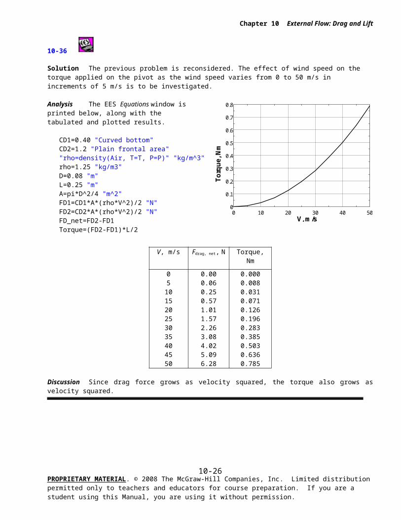
Solution The previous problem is reconsidered. The effect of wind speed on the torque applied on the pivot as the wind speed varies from 0 to 50 m/s in increments of 5 m/s is to be investigated.
Analysis The EES Equations window is printed below, along with the tabulated and plotted results.
CD1=0.40 "Curved bottom"CD2=1.2 "Plain frontal area""rho=density(Air, T=T, P=P)" "kg/m^3"rho=1.25 "kg/m3"D=0.08 "m"L=0.25 "m"A=pi*D^2/4 "m^2"FD1=CD1*A*(rho*V^2)/2 "N"FD2=CD2*A*(rho*V^2)/2 "N"FD_net=FD2-FD1Torque=(FD2-FD1)*L/2
V, m/s Fdrag, net, N Torque, Nm
05101520253035404550
0.000.060.250.571.011.572.263.084.025.096.28
0.0000.0080.0310.0710.1260.1960.2830.3850.5030.6360.785
Discussion Since drag force grows as velocity squared, the torque also grows as velocity squared.
PROPRIETARY MATERIAL. © 2008 The McGraw-Hill Companies, Inc. Limited distribution permitted only to teachers and educators for course preparation. If you are a student using this Manual, you are using it without permission.
0 10 20 30 40 500
0.1
0.2
0.3
0.4
0.5
0.6
0.7
0.8
V, m/s
To
rqu
e, N
m
10-18
5 ft
Water
12 ft/s
Chapter 10 External Flow: Drag and Lift
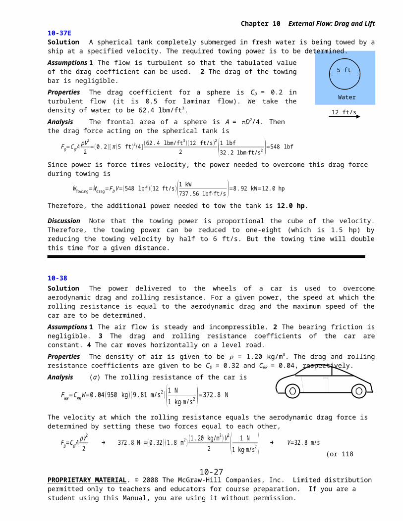
10-37E Solution A spherical tank completely submerged in fresh water is being towed by a ship at a specified velocity. The required towing power is to be determined.
Assumptions 1 The flow is turbulent so that the tabulated value of the drag coefficient can be used. 2 The drag of the towing bar is negligible.
Properties The drag coefficient for a sphere is CD = 0.2 in turbulent flow (it is 0.5 for laminar flow). We take the density of water to be 62.4 lbm/ft3.
Analysis The frontal area of a sphere is A = D2/4. Then the drag force acting on the spherical tank is
FD=CD AρV 2
2=(0 .2)[ π (5 ft )2/ 4 ]
(62.4 lbm/ft3 )(12 ft/s )2
2 (1 lbf32. 2 lbm⋅ft/s2 )=548 lbf
Since power is force times velocity, the power needed to overcome this drag force during towing is
W Towing=W drag=FD V=(548 lbf )(12 ft/s )(1 kW
737 .56 lbf⋅ft/s )=8 . 92 kW=12.0 hp
Therefore, the additional power needed to tow the tank is 12.0 hp.
Discussion Note that the towing power is proportional the cube of the velocity. Therefore, the towing power can be reduced to one-eight (which is 1.5 hp) by reducing the towing velocity by half to 6 ft/s. But the towing time will double this time for a given distance.
10-38 Solution The power delivered to the wheels of a car is used to overcome aerodynamic drag and rolling resistance. For a given power, the speed at which the rolling resistance is equal to the aerodynamic drag and the maximum speed of the car are to be determined.
Assumptions 1 The air flow is steady and incompressible. 2 The bearing friction is negligible. 3 The drag and rolling resistance coefficients of the car are constant. 4 The car moves horizontally on a level road.
Properties The density of air is given to be = 1.20 kg/m3. The drag and rolling resistance coefficients are given to be CD = 0.32 and CRR = 0.04, respectively.
Analysis (a) The rolling resistance of the car is
FRR=CRR W=0 . 04(950 kg )(9 . 81 m/s2 )(1 N
1 kg⋅m/s2 )=372 .8 N
The velocity at which the rolling resistance equals the aerodynamic drag force is determined by setting these two forces equal to each other,
FD=CD AρV 2
2 → 372 . 8 N =(0 .32 )(1.8 m2)
(1 .20 kg/m3 )V 2
2 ( 1 N1 kg⋅m/s2 ) → V =32. 8 m/s
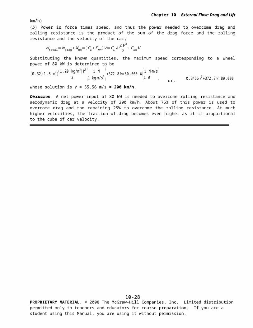
(or 118 km/h)(b) Power is force times speed, and thus the power needed to overcome drag and rolling resistance is the product of the sum of the drag force and the rolling resistance and the velocity of the car,
W total=W drag+W RR=(F D+FRR )V =CD AρV 3
2+FRR V
Substituting the known quantities, the maximum speed corresponding to a wheel power of 80 kW is determined to be
(0 .32 )(1.8 m2 )(1 .20 kg/m3 )V 3
2 ( 1 N1 kg⋅m/s2 )+372 .8V =80 ,000 W ( 1 N⋅m/s
1 W ) or, 0 .3456 V 3+372 .8V =80 ,000
whose solution is V = 55.56 m/s = 200 km/h.
Discussion A net power input of 80 kW is needed to overcome rolling resistance and aerodynamic drag at a velocity of 200 km/h. About 75% of this power is used to overcome drag and the remaining 25% to overcome the rolling resistance. At much higher velocities, the fraction of drag becomes even higher as it is proportional to the cube of car velocity.
PROPRIETARY MATERIAL. © 2008 The McGraw-Hill Companies, Inc. Limited distribution permitted only to teachers and educators for course preparation. If you are a student using this Manual, you are using it without permission.
10-19
Chapter 10 External Flow: Drag and Lift
PROPRIETARY MATERIAL. © 2008 The McGraw-Hill Companies, Inc. Limited distribution permitted only to teachers and educators for course preparation. If you are a student using this Manual, you are using it without permission.
10-20
Chapter 10 External Flow: Drag and Lift
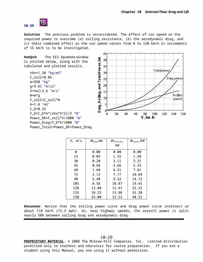
10-39
Solution The previous problem is reconsidered. The effect of car speed on the required power to overcome (a) rolling resistance, (b) the aerodynamic drag, and (c) their combined effect as the car speed varies from 0 to 150 km/h in increments of 15 km/h is to be investigated.
Analysis The EES Equations window is printed below, along with the tabulated and plotted results.
rho=1.20 "kg/m3"C_roll=0.04m=950 "kg"g=9.81 "m/s2"V=Vel/3.6 "m/s"W=m*gF_roll=C_roll*WA=1.8 "m2"C_D=0.32F_D=C_D*A*(rho*V^2)/2 "N"Power_RR=F_roll*V/1000 "W"Power_Drag=F_D*V/1000 "W"Power_Total=Power_RR+Power_Drag
V, m/s Wdrag kW Wrolling, kW Wtotal, kW
0153045607590105120135150
0.000.030.200.681.603.135.408.5812.8018.2325.00
0.001.553.114.666.217.779.3210.8712.4313.9815.53
0.001.583.315.337.8110.8914.7219.4525.2332.2040.53
Discussion Notice that the rolling power curve and drag power curve intersect at about 118 km/h (73.3 mph). So, near highway speeds, the overall power is split nearly 50% between rolling drag and aerodynamic drag.
PROPRIETARY MATERIAL. © 2008 The McGraw-Hill Companies, Inc. Limited distribution permitted only to teachers and educators for course preparation. If you are a student using this Manual, you are using it without permission.
0 20 40 60 80 100 120 140 1600
5
10
15
20
25
30
35
40
45
V, km/h
Dra
g, R
olli
ng
, an
d T
ota
l Po
wer
, kW
Rolling
Drag power
Total power
power
10-21
40 km/h
Submarine
Chapter 10 External Flow: Drag and Lift
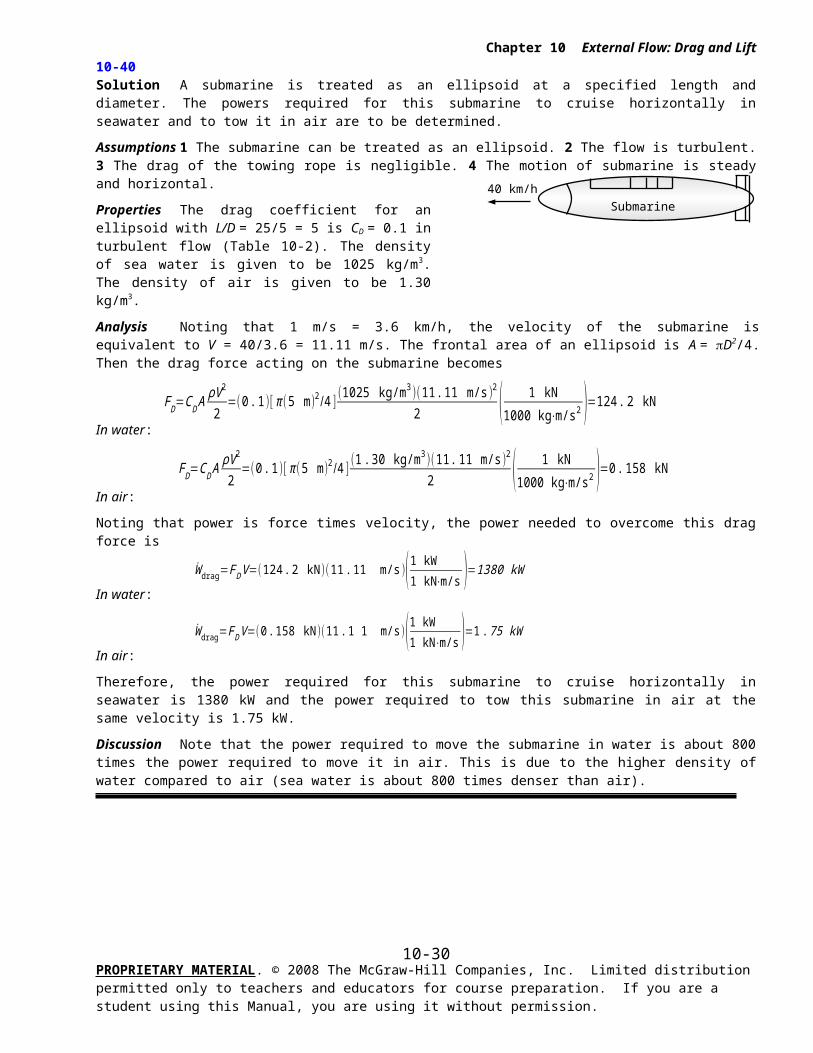
10-40 Solution A submarine is treated as an ellipsoid at a specified length and diameter. The powers required for this submarine to cruise horizontally in seawater and to tow it in air are to be determined.
Assumptions 1 The submarine can be treated as an ellipsoid. 2 The flow is turbulent. 3 The drag of the towing rope is negligible. 4 The motion of submarine is steady and horizontal.
Properties The drag coefficient for an ellipsoid with L/D = 25/5 = 5 is CD = 0.1 in turbulent flow (Table 10-2). The density of sea water is given to be 1025 kg/m3. The density of air is given to be 1.30 kg/m3.
Analysis Noting that 1 m/s = 3.6 km/h, the velocity of the submarine is equivalent to V = 40/3.6 = 11.11 m/s. The frontal area of an ellipsoid is A = D2/4. Then the drag force acting on the submarine becomes
In water:
FD=CD AρV 2
2=(0 .1 )[ π (5 m )2 /4 ]
(1025 kg/m3 )(11. 11 m/s )2
2 ( 1 kN1000 kg⋅m/s2 )=124 .2 kN
In air:
FD=CD AρV 2
2=(0 .1 )[ π (5 m)2 /4 ]
(1 .30 kg/m3 )(11. 11 m/s)2
2 ( 1 kN1000 kg⋅m/s2 )=0. 158 kN
Noting that power is force times velocity, the power needed to overcome this drag force is
In water:
W drag=FD V =(124 .2 kN )(11.11 m/s )(1 kW1 kN⋅m/s )=1380 kW
In air:
W drag=FD V =(0 . 158 kN )(11. 1 1 m/s )(1 kW1 kN⋅m/s )=1 .75 kW
Therefore, the power required for this submarine to cruise horizontally in seawater is 1380 kW and the power required to tow this submarine in air at the same velocity is 1.75 kW.
Discussion Note that the power required to move the submarine in water is about 800 times the power required to move it in air. This is due to the higher density of water compared to air (sea water is about 800 times denser than air).
PROPRIETARY MATERIAL. © 2008 The McGraw-Hill Companies, Inc. Limited distribution permitted only to teachers and educators for course preparation. If you are a student using this Manual, you are using it without permission.
10-22
1.2 mV
Garbagecan
D = 0.8 m
Chapter 10 External Flow: Drag and Lift
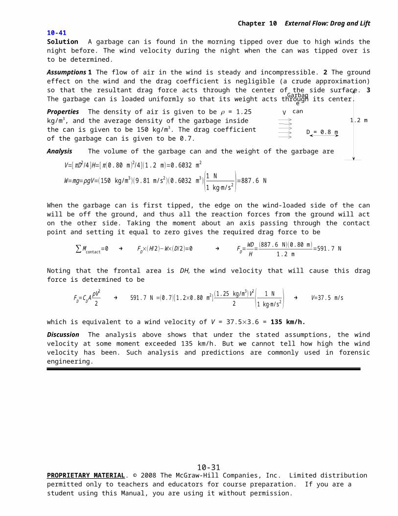
10-41 Solution A garbage can is found in the morning tipped over due to high winds the night before. The wind velocity during the night when the can was tipped over is to be determined.
Assumptions 1 The flow of air in the wind is steady and incompressible. 2 The ground effect on the wind and the drag coefficient is negligible (a crude approximation) so that the resultant drag force acts through the center of the side surface. 3 The garbage can is loaded uniformly so that its weight acts through its center.
Properties The density of air is given to be = 1.25 kg/m3, and the average density of the garbage inside the can is given to be 150 kg/m3. The drag coefficient of the garbage can is given to be 0.7.
Analysis The volume of the garbage can and the weight of the garbage are
V=[ πD2 /4 ]H=[ π (0 .80 m)2 /4 ](1.2 m )=0 .6032 m2
W=mg=ρgV =(150 kg/m3 )(9 . 81 m/s2 )(0 .6032 m3 )(1 N
1 kg⋅m/s2 )=887 . 6 N
When the garbage can is first tipped, the edge on the wind-loaded side of the can will be off the ground, and thus all the reaction forces from the ground will act on the other side. Taking the moment about an axis passing through the contact point and setting it equal to zero gives the required drag force to be
∑M contact=0 → FD×(H /2 )−W×(D /2)=0 → FD=WDH
=(887 .6 N )(0 .80 m )
1 .2 m=591.7 N
Noting that the frontal area is DH, the wind velocity that will cause this drag force is determined to be
FD=CD AρV 2
2 → 591.7 N =(0 . 7)[ 1. 2×0. 80 m2 ]
(1. 25 kg/m3 )V 2
2 ( 1 N1 kg⋅m/s2 ) → V =37 .5 m/s
which is equivalent to a wind velocity of V = 37.53.6 = 135 km/h.
Discussion The analysis above shows that under the stated assumptions, the wind velocity at some moment exceeded 135 km/h. But we cannot tell how high the wind velocity has been. Such analysis and predictions are commonly used in forensic engineering.
PROPRIETARY MATERIAL. © 2008 The McGraw-Hill Companies, Inc. Limited distribution permitted only to teachers and educators for course preparation. If you are a student using this Manual, you are using it without permission.
10-23
Chapter 10 External Flow: Drag and Lift
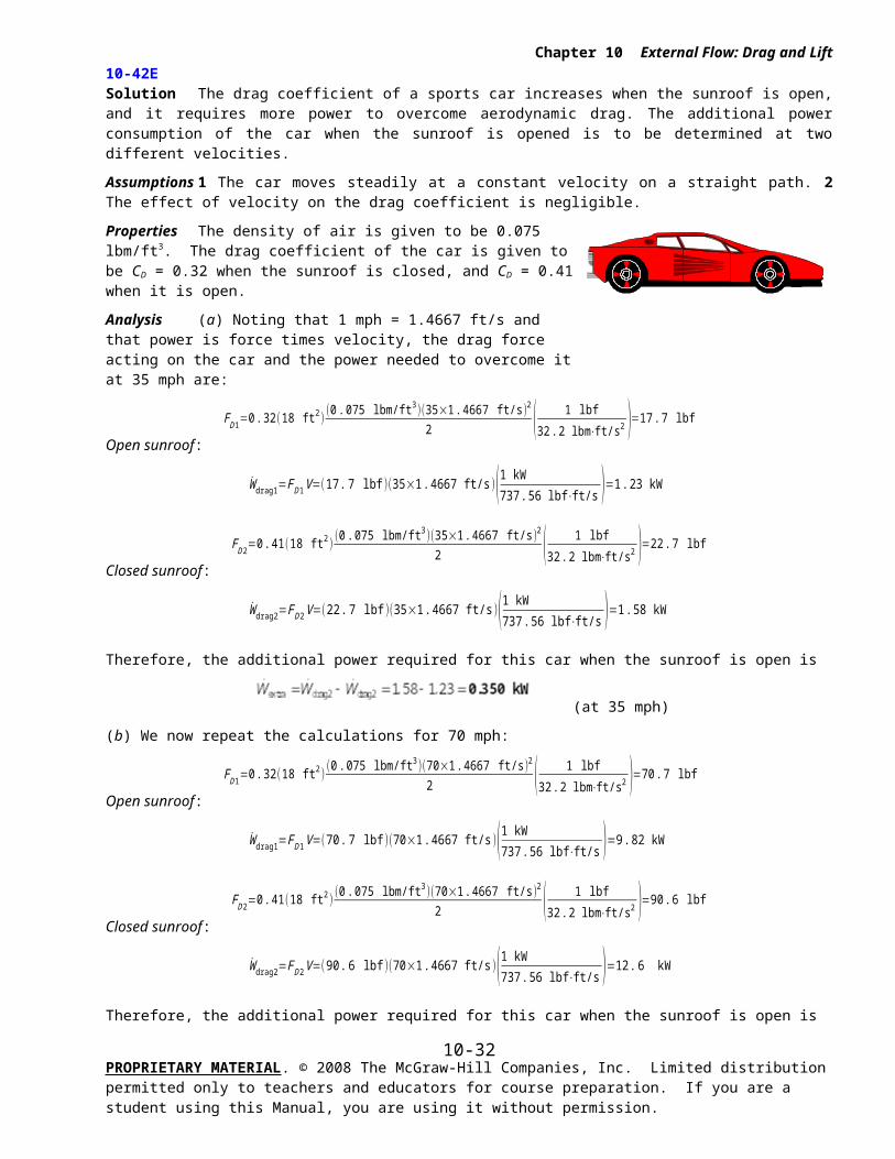
10-42E Solution The drag coefficient of a sports car increases when the sunroof is open, and it requires more power to overcome aerodynamic drag. The additional power consumption of the car when the sunroof is opened is to be determined at two different velocities.
Assumptions 1 The car moves steadily at a constant velocity on a straight path. 2 The effect of velocity on the drag coefficient is negligible.
Properties The density of air is given to be 0.075 lbm/ft3. The drag coefficient of the car is given to be CD = 0.32 when the sunroof is closed, and CD = 0.41 when it is open.
Analysis (a) Noting that 1 mph = 1.4667 ft/s and that power is force times velocity, the drag force acting on the car and the power needed to overcome it at 35 mph are:
Open sunroof:
FD1=0 .32(18 ft2 )(0 .075 lbm/ft3 )(35×1.4667 ft/s )2
2 ( 1 lbf32 .2 lbm⋅ft/s2 )=17 .7 lbf
W drag1=FD 1V =(17 . 7 lbf )(35×1 .4667 ft/s)(1 kW737 . 56 lbf⋅ft/s )=1. 23 kW
Closed sunroof:
FD 2=0 .41(18 ft2 )(0 .075 lbm/ft3 )(35×1 .4667 ft/s)2
2 ( 1 lbf32.2 lbm⋅ft/s2 )=22 .7 lbf
W drag2=FD 2V=(22 .7 lbf )(35×1. 4667 ft/s )(1 kW737 .56 lbf⋅ft/s )=1 .58 kW
Therefore, the additional power required for this car when the sunroof is open is
(at 35 mph)
(b) We now repeat the calculations for 70 mph:
Open sunroof:
FD1=0 .32(18 ft2 )(0 .075 lbm/ft3 )(70×1.4667 ft/s)2
2 ( 1 lbf32 .2 lbm⋅ft/s2 )=70.7 lbf
W drag1=FD 1V =(70 .7 lbf )(70×1 .4667 ft/s)(1 kW737 .56 lbf⋅ft/s )=9.82 kW
Closed sunroof:
FD 2=0 .41(18 ft2 )(0 .075 lbm/ft3 )(70×1 .4667 ft/s)2
2 ( 1 lbf32.2 lbm⋅ft/s2 )=90 .6 lbf
W drag2=FD 2V=(90.6 lbf )(70×1 .4667 ft/s )(1 kW737 . 56 lbf⋅ft/s )=12.6 kW
Therefore, the additional power required for this car when the sunroof is open is
W extra=W drag2−W drag2=12. 6−9 . 82=2 .78 kW
(at 70 mph)
Discussion Note that the additional drag caused by open sunroof is 0.35 kW at 35 mph, and 2.78 kW at 70 mph, which is an increase of 8 folds when the velocity is doubled. This is expected since the power consumption to overcome drag is proportional to the cube of velocity.
PROPRIETARY MATERIAL. © 2008 The McGraw-Hill Companies, Inc. Limited distribution permitted only to teachers and educators for course preparation. If you are a student using this Manual, you are using it without permission.
10-24
Chapter 10 External Flow: Drag and Lift
PROPRIETARY MATERIAL. © 2008 The McGraw-Hill Companies, Inc. Limited distribution permitted only to teachers and educators for course preparation. If you are a student using this Manual, you are using it without permission.
10-25
Chapter 10 External Flow: Drag and Lift
Flow over Flat Plates
10-43C Solution We are to discuss the fluid property responsible for the development of a boundary layer.
Analysis The fluid viscosity is responsible for the development of the velocity boundary layer. Velocity forces the boundary layer closer to the wall. Therefore, the higher the velocity (and thus Reynolds number), the lower the thickness of the boundary layer.
Discussion All fluids have viscosity – a measure of frictional forces in a fluid. There is no such thing as an inviscid fluid, although there are regions, called inviscid flow regions, in which viscous effects are negligible.
10-44C Solution We are to define and discuss the friction coefficient for flow over a flat plate.
Analysis The friction coefficient represents the resistance to fluid flow over a flat plate. It is proportional to the drag force acting on the plate. The drag coefficient for a flat surface is equivalent to the mean friction coefficient.
Discussion In flow over a flat plate aligned with the flow, there is no pressure (form) drag – only friction drag.
10-45C Solution We are to discuss how the local skin friction coefficient changes with position along a flat plate in laminar flow.
Analysis The local friction coefficient decreases with downstream distance in laminar flow over a flat plate.
Discussion At the front of the plate, the boundary layer is very thin, and thus the shear stress at the wall is large. As the boundary layer grows downstream, however, the boundary layer grows in size, decreasing the wall shear stress.
10-46C Solution We are to define and discuss the average skin friction coefficient over a flat plate.
Analysis The average friction coefficient in flow over a flat plate is determined by integrating the local friction coefficient over the entire length of the plate, and then dividing it by the length of the plate. Or, it can be determined experimentally by measuring the drag force, and dividing it by the dynamic pressure.
Discussion For the case of a flat plate aligned with the flow, there is no pressure drag, only skin friction drag. Thus, the average friction coefficient is the same as the drag coefficient. This is not true for other body shapes.
PROPRIETARY MATERIAL. © 2008 The McGraw-Hill Companies, Inc. Limited distribution permitted only to teachers and educators for course preparation. If you are a student using this Manual, you are using it without permission.
10-26
6 ft/s
Oil
L = 15 ft
Chapter 10 External Flow: Drag and Lift
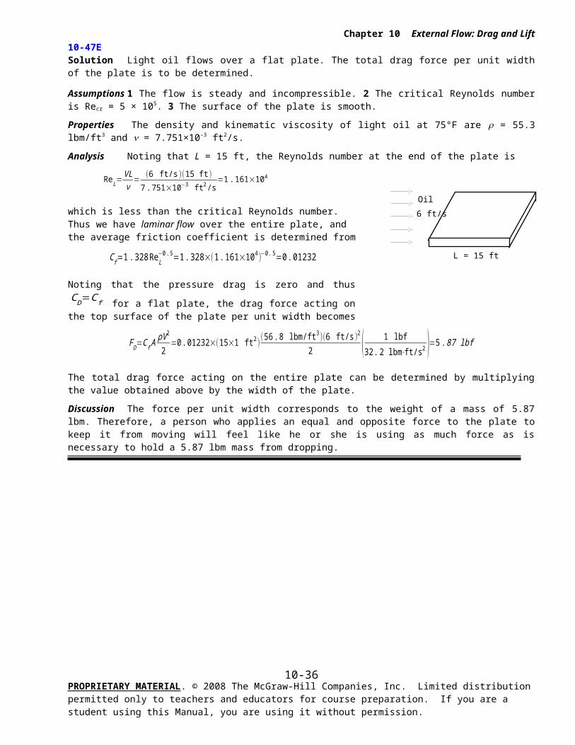
10-47E Solution Light oil flows over a flat plate. The total drag force per unit width of the plate is to be determined.
Assumptions 1 The flow is steady and incompressible. 2 The critical Reynolds number is Recr = 5 × 10⁵. 3 The surface of the plate is smooth.
Properties The density and kinematic viscosity of light oil at 75°F are = 55.3 lbm/ft3 and = 7.751×10⁻³ ft2/s.
Analysis Noting that L = 15 ft, the Reynolds number at the end of the plate is
ReL=VLν=
(6 ft/s)(15 ft )7 . 751×10−3 ft2 /s
=1 . 161×104
which is less than the critical Reynolds number. Thus we have laminar flow over the entire plate, and the average friction coefficient is determined from
C f=1 .328 ReL
−0. 5=1. 328×(1 .161×104 )−0 . 5=0. 01232
Noting that the pressure drag is zero and thus CD=C f for a flat plate, the
drag force acting on the top surface of the plate per unit width becomes
FD=C f AρV 2
2=0 .01232×(15×1 ft2 )
(56 . 8 lbm/ft3 )(6 ft/s)2
2 ( 1 lbf32 .2 lbm⋅ft/s2 )=5.87 lbf
The total drag force acting on the entire plate can be determined by multiplying the value obtained above by the width of the plate.
Discussion The force per unit width corresponds to the weight of a mass of 5.87 lbm. Therefore, a person who applies an equal and opposite force to the plate to keep it from moving will feel like he or she is using as much force as is necessary to hold a 5.87 lbm mass from dropping.
PROPRIETARY MATERIAL. © 2008 The McGraw-Hill Companies, Inc. Limited distribution permitted only to teachers and educators for course preparation. If you are a student using this Manual, you are using it without permission.
10-27
Air
6 m/s
8 m
2.5 m
Chapter 10 External Flow: Drag and Lift
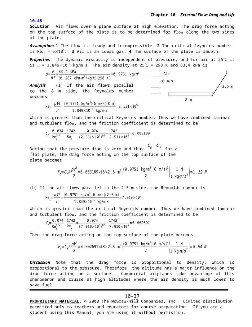
10-48 Solution Air flows over a plane surface at high elevation. The drag force acting on the top surface of the plate is to be determined for flow along the two sides of the plate.
Assumptions 1 The flow is steady and incompressible. 2 The critical Reynolds number is Recr = 5105. 3 Air is an ideal gas. 4 The surface of the plate is smooth.
Properties The dynamic viscosity is independent of pressure, and for air at 25 C it is m = 1.84910-5 kg/m×s. The air density at 25C = 298 K and 83.4 kPa is
ρ= PRT
=83. 4 kPa
( 0.287 kPa⋅m3 /kg⋅K )(298 K )=0 .9751 kg/m3
Analysis (a) If the air flows parallel to the 8 m side, the Reynolds number becomes
ReL=ρ VL
μ=(0.9751 kg/m3 )(6 m/s )(8 m)
1. 849×10−5 kg/m⋅s=2 .531×106
which is greater than the critical Reynolds number. Thus we have combined laminar and turbulent flow, and the friction coefficient is determined to be
C f=0 . 074
ReL1/5
−1742ReL
= 0 .074
(2. 531×106 )1/5−1742
2 . 531×106=0 .003189
Noting that the pressure drag is zero and thus CD=C f for a flat plate, the drag force acting
on the top surface of the plate becomes
FD=C f AρV 2
2=0 .003189×(8×2 .5 m2 )
(0. 9751 kg/m3 )(6 m/s )2
2 ( 1 N1 kg⋅m/s2 )=1. 12 N
(b) If the air flows parallel to the 2.5 m side, the Reynolds number is
ReL=ρ VL
μ=(0. 9751 kg/m3 )(6 m/s )(2 . 5 m)
1 . 849×10−5 kg/m⋅s=7 .910×105
which is greater than the critical Reynolds number. Thus we have combined laminar and turbulent flow, and the friction coefficient is determined to be
C f=0 . 074
ReL1/5
−1742ReL
= 0 .074
(7. 910×105 )1/5−1742
7 . 910×105=0 .002691
Then the drag force acting on the top surface of the plate becomes
FD=C f AρV 2
2=0 .002691×(8×2 .5 m2 )
(0 . 9751 kg/m3 )(6 m/s)2
2 ( 1 N1 kg⋅m/s2 )=0 .94 N
Discussion Note that the drag force is proportional to density, which is proportional to the pressure. Therefore, the altitude has a major influence on the drag force acting on a surface. Commercial airplanes take advantage of this phenomenon and cruise at high altitudes where the air density is much lower to save fuel.
PROPRIETARY MATERIAL. © 2008 The McGraw-Hill Companies, Inc. Limited distribution permitted only to teachers and educators for course preparation. If you are a student using this Manual, you are using it without permission.
10-28
10 m
4 m
Air55 km/h
Chapter 10 External Flow: Drag and Lift
10-49 Solution Wind is blowing parallel to the side wall of a house. The drag force acting on the wall is to be determined for two different wind velocities.
Assumptions 1 The flow is steady and incompressible. 2 The critical Reynolds number is Recr = 5105. 3 Air is an ideal gas. 4 The wall surface is smooth (the actual wall surface is usually very rough). 5 The wind blows parallel to the wall.
Properties The density and kinematic viscosity of air at 1 atm and 5C are = 1.269 kg/m3 and = 1.382×10⁻⁵ m2/s .
Analysis The Reynolds number is
which is greater than the critical Reynolds number. Thus we have combined laminar and turbulent flow, and the friction coefficient is
C f=0 . 074
ReL1/5
−1742ReL
= 0 .074
(1. 105×107 )1 /5−1742
1 . 105×107=0 . 002730
Noting that the pressure drag is zero and thus CD=C f for a flat plate, the drag force acting on the wall surface is
FD=C f AρV 2
2=0 .00273×(10×4 m2)
(1 .269 kg/m3 )(55/3 .6 m/s )2
2 ( 1 N1 kg⋅m/s2 )=16 .2 N
(b) When the wind velocity is doubled to 110 km/h, the Reynolds number becomes
which is greater than the critical Reynolds number. Thus we have combined laminar and turbulent flow, and the friction coefficient and the drag force become
C f=0 .074
ReL1/5
−1742ReL
= 0 .074
(2.211×10⁷ )1/5−1742
2.211×107=0.002435
FD=C f AρV 2
2=0 .002435×(10×4 m2)
(1 .269 kg/m3 )(110 /3. 6 m/s )2
2 ( 1 N1 kg⋅m/s2 )=57 . 7 N
Treating flow over the side wall of a house as flow over a flat plate is not quite realistic. When flow hits a bluff body like a house, it separates at the sharp corner and a separation bubble exists over most of the side panels of the house. Therefore, flat plat boundary layer equations are not appropriate for this problem, and the entire house should considered in the solution instead.
Discussion Note that the actual drag will probably be much higher since the wall surfaces are typically very rough. Also, we can solve this problem using the turbulent flow relation (instead of the combined laminar-turbulent flow relation) without much loss in accuracy. Finally, the drag force nearly quadruples when the velocity is doubled. This is expected since the drag force is proportional to the square of the velocity, and the effect of velocity on the friction coefficient is small.
PROPRIETARY MATERIAL. © 2008 The McGraw-Hill Companies, Inc. Limited distribution permitted only to teachers and educators for course preparation. If you are a student using this Manual, you are using it without permission.
10-29
25 ft/s
Air
10 ft
Chapter 10 External Flow: Drag and Lift
10-50E
Solution Air flows over a flat plate. The local friction coefficients at intervals of 1 ft is to be determined and plotted against the distance from the leading edge.
Assumptions 1 The flow is steady and incompressible. 2 The critical Reynolds number is Recr = 5105. 3 Air is an ideal gas. 4 The surface of the plate is smooth.
Properties The density and kinematic viscosity of air at 1 atm and 70°F are = 0.07489 lbm/ft3 and = 0.5913 ft2/h = 1.643×10⁻⁴ ft2/s .
Analysis For the first 1 ft interval, the Reynolds number is
which is less than the critical value of . Therefore, the flow is laminar. The local friction coefficient is
C f , x=0 .664
Re0. 5= 0 .664
(1.522×10⁵)0 . 5=0 .001702
We repeat calculations for all 1-ft intervals. The EES Equations window is printed below, along with the tabulated and plotted results.
x, ft Re Cf
12345678910
1.522E+053.044E+054.566E+056.088E+057.610E+059.132E+051.065E+061.218E+061.370E+061.522E+06
0.0017020.0012030.0009830.0041110.0039320.0037910.0036760.0035790.0034960.003423
Discussion Note that the Reynolds number exceeds the critical value for x > 3 ft, and thus the flow is turbulent over
most of the plate. For x > 3 ft, we used C f=0 . 074 /ReL1 /5 -1742/ReL for friction coefficient. Note that Cf decreases with
Re in both laminar and turbulent flows.
PROPRIETARY MATERIAL. © 2008 The McGraw-Hill Companies, Inc. Limited distribution permitted only to teachers and educators for course preparation. If you are a student using this Manual, you are using it without permission.
rho=0.07489 "lbm/ft3"nu=0.5913/3600 "ft2/s"V=25 “Local Re and C_f”Re=x*V/nu"f=0.664/Re^0.5"f=0.059/Re^0.2
1 2 3 4 5 6 7 8 9 100.0005
0.001
0.0015
0.002
0.0025
0.003
0.0035
0.004
0.0045
x, ft
f
10-30
Plastic sheet
AirV = 3 m/s
15 m/min
70 km/h
Air, 25C
Chapter 10 External Flow: Drag and Lift
10-51 Solution Air flows on both sides of a continuous sheet of plastic. The drag force air exerts on the plastic sheet in the direction of flow is to be determined.
Assumptions 1 The flow is steady and incompressible. 2 The critical Reynolds number is Recr = 5105. 3 Air is an ideal gas. 4 Both surfaces of the plastic sheet are smooth. 5 The plastic sheet does not vibrate and thus it does not induce turbulence in air flow.
Properties The density and kinematic viscosity of air at 1 atm and 60C are = 1.059 kg/m3 and = 1.896×10⁻⁵ m2/s .
Analysis The length of the cooling section is
L=V sheet Δt=[(15/60) m/s ](2 s )=0 .5 m
The Reynolds number is
which is less than the critical Reynolds number. Thus the flow is laminar. The area on both sides of the sheet exposed to air flow is
A=2 wL=2(1.2 m )(0 .5 m )=1 .2 m2
Then the friction coefficient and the drag force become
C f=1 . 328Re
L0 . 5
= 1 .328
(1. 899×105 )0. 5=0 . 003048
FD=C f AρV 2
2=( 0.003048 )(1.2 m2 )
(1.059 kg/m3 )(3 m/s )2
2=0 .0174 N
Discussion Note that the Reynolds number remains under the critical value, and thus the flow remains laminar over the entire plate. In reality, the flow may be turbulent because of the motion of the plastic sheet.
10-52 Solution A train is cruising at a specified velocity. The drag force acting on the top surface of a passenger car of the train is to be determined.
Assumptions 1 The air flow is steady and incompressible. 2 The critical Reynolds number is Recr = 5105. 3 Air is an ideal gas. 4 The top surface of the train is smooth (in reality it can be rough). 5 The air is calm (no significant winds).
Properties The density and kinematic viscosity of air at 1 atm and 25C are = 1.184 kg/m3 and = 1.562×10⁻⁵ m2/s .
Analysis The Reynolds number is
which is greater than the critical Reynolds number. Thus we have combined laminar and turbulent flow, and the friction coefficient is determined to be
C f=0 .074
ReL1/5
−1742ReL
= 0 .074
(9 .959×106 )1/5−1742
9 .959×106=0 .002774
Noting that the pressure drag is zero and thus CD=C f for a flat plate, the drag force acting on the surface becomes
FD=C f AρV 2
2=0 .002774×(8×3 .2 m2)
(1 .184 kg/m3 )(70 /3. 6 m/s )2
2 ( 1 N1 kg⋅m/s2 )=15 . 9 N
PROPRIETARY MATERIAL. © 2008 The McGraw-Hill Companies, Inc. Limited distribution permitted only to teachers and educators for course preparation. If you are a student using this Manual, you are using it without permission.
10-31
Air, 10 m/s
50 cm
50 cm
Plate
V
L
Chapter 10 External Flow: Drag and Lift
Discussion Note that we can solve this problem using the turbulent flow relation (instead of the combined laminar-turbulent flow relation) without much loss in accuracy since the Reynolds number is much greater than the critical value. Also, the actual drag force will probably be greater because of the surface roughness effects.
10-53 Solution The weight of a thin flat plate exposed to air flow on both sides is balanced by a counterweight. The mass of the counterweight that needs to be added in order to balance the plate is to be determined.
Assumptions 1 The flow is steady and incompressible. 2 The critical Reynolds number is Recr = 5105. 3 Air is an ideal gas. 4 The surfaces of the plate are smooth.
Properties The density and kinematic viscosity of air at 1 atm and 25C are = 1.184 kg/m3 and = 1.562×10⁻⁵ m2/s .
Analysis The Reynolds number is
which is less than the critical Reynolds number of 5105 . Therefore the flow is laminar. The average friction coefficient, drag force and the corresponding mass are
C f=1 . 328Re
L0 . 5
= 1 .328
(3. 201×105)0. 5=0 . 002347
FD=C f AρV 2
2=( 0. 002347 )[(2×0 . 5×0 . 5) m2 ]
(1. 184 kg/m3 )(10 m/s )2
2=0 . 0695 kg⋅m/s2=0 . 0695 N
The mass whose weight is 0.0695 N is
m=FD
g=0 . 0695 kg . m/s2
9 .81 m/s2=0 . 0071 kg=7 .1 g
Therefore, the mass of the counterweight must be 7.1 g to counteract the drag force acting on the plate.
Discussion Note that the apparatus described in this problem provides a convenient mechanism to measure drag force and thus drag coefficient.
10-54 Solution Laminar flow of a fluid over a flat plate is considered. The change in the drag force is to be determined when the free-stream velocity of the fluid is doubled.
Analysis For the laminar flow of a fluid over a flat plate the drag force is given by
F D 1=C f AρV 2
2 where C f=
1.328Re0 .5
Therefore
F D 1=1 .328Re0 .5
AρV 2
2Substituting Reynolds number relation, we get
F D 1=1 .328
(VLυ )
0. 5A
ρV 2
2=0 .664V 3/2 A
υ0 .5
L0 .5
When the free-stream velocity of the fluid is doubled, the new value of the drag force on the plate becomes
FD 2=1 .328
((2 V )Lυ )
0 .5A
ρ(2V )2
2=0. 664 (2V )3/2 A
υ0 .5
L0 .5
The ratio of drag forces corresponding to V and 2V is
PROPRIETARY MATERIAL. © 2008 The McGraw-Hill Companies, Inc. Limited distribution permitted only to teachers and educators for course preparation. If you are a student using this Manual, you are using it without permission.
10-32
Chapter 10 External Flow: Drag and Lift
F D 2
F D 1
=(2 V )3 /2
V 3 /2 =23/2=2. 83
Discussion Note that the drag force increases almost three times in laminar flow when the fluid velocity is doubled.
PROPRIETARY MATERIAL. © 2008 The McGraw-Hill Companies, Inc. Limited distribution permitted only to teachers and educators for course preparation. If you are a student using this Manual, you are using it without permission.
10-33
Chapter 10 External Flow: Drag and Lift
10-55E Solution A refrigeration truck is traveling at a specified velocity. The drag force acting on the top and side surfaces of the truck and the power needed to overcome it are to be determined.
Assumptions 1 The process is steady and incompressible. 2 The airflow over the entire outer surface is turbulent because of constant agitation. 3 Air is an ideal gas. 4 The top and side surfaces of the truck are smooth (in reality they can be rough). 5 The air is calm (no significant winds).
Properties The density and kinematic viscosity of air at 1 atm and 80 F are = 0.07350 lbm/ft3 and = 0.6110 ft2/s = 1.697×10⁻⁴ ft2/s .
Analysis The Reynolds number is
The air flow over the entire outer surface is assumed to be turbulent. Then the friction coefficient becomes
C f=0 . 074
ReL1/5
= 0 .074
(1 .124×107 )1/5=0 .002878
The area of the top and side surfaces of the truck is
A = Atop + 2Aside = 920+2820 =500 ft2
Noting that the pressure drag is zero and thus CD=C f for a plane surface, the drag force acting on these surfaces becomes
FD=C f AρV 2
2=0 .002878×(500 ft2 )
(0 .07350 lbm/ft3 )(65×1.4667 ft/s )2
2 ( 1 lbf32 . 2 lbm⋅ft/s2 )=14 .9 lbf
Noting that power is force times velocity, the power needed to overcome this drag force is
W drag=FD V =(14 .9 lbf )(65×1 .4667 ft/s)(1 kW737 .56 lbf⋅ft/s )=1.93 kW
Discussion Note that the calculated drag force (and the power required to overcome it) is very small. This is not surprising since the drag force for blunt bodies is almost entirely due to pressure drag, and the friction drag is practically negligible compared to the pressure drag.
PROPRIETARY MATERIAL. © 2008 The McGraw-Hill Companies, Inc. Limited distribution permitted only to teachers and educators for course preparation. If you are a student using this Manual, you are using it without permission.
20
8 Refrigerationtruck
Air65
10-34
Chapter 10 External Flow: Drag and Lift
10-56E
Solution The previous problem is reconsidered. The effect of truck speed on the total drag force acting on the top and side surfaces, and the power required to overcome as the truck speed varies from 0 to 100 mph in increments of 10 mph is to be investigated.
Analysis The EES Equations window is printed below, along with the tabulated and plotted results.
rho=0.07350 "lbm/ft3"nu=0.6110/3600 "ft2/s"V=Vel*1.4667 "ft/s"L=20 "ft"W=2*8+9A=L*WRe=L*V/nuCf=0.074/Re^0.2g=32.2 "ft/s2"F=Cf*A*(rho*V^2)/2/32.2 "lbf"Pdrag=F*V/737.56 "kW"
V, mph Re Fdrag, lbf Pdrag, kW
0102030405060708090100
01.728E+063.457E+065.185E+066.913E+068.642E+061.037E+071.209E+071.382E+071.555E+071.728E+07
0.000.511.793.716.239.3112.9317.0621.6926.8232.42
0.0000.0100.0710.2210.4960.9261.5422.3753.4514.7996.446
Discussion The required power increases rapidly with velocity – in fact, as velocity cubed.
PROPRIETARY MATERIAL. © 2008 The McGraw-Hill Companies, Inc. Limited distribution permitted only to teachers and educators for course preparation. If you are a student using this Manual, you are using it without permission.
0 20 40 60 80 1000
1
2
3
4
5
6
7
V, mph P
dra
g, k
W
10-35
V
xcr
V
xcr
Chapter 10 External Flow: Drag and Lift
10-57 Solution Air is flowing over a long flat plate with a specified velocity. The distance from the leading edge of the plate where the flow becomes turbulent, and the thickness of the boundary layer at that location are to be determined.
Assumptions 1 The flow is steady and incompressible. 2 The critical Reynolds number is Recr = 5105. 3 Air is an ideal gas. 4 The surface of the plate is smooth.
Properties The density and kinematic viscosity of air at 1 atm and 25C are = 1.184 kg/m3 and = 1.562×10⁻⁵ m2/s .
Analysis The critical Reynolds number is given to be Recr = 5105. The distance from the leading edge of the plate where the flow becomes turbulent is the distance xcr where the Reynolds number becomes equal to the critical Reynolds number,
The thickness of the boundary layer at that location is obtained by substituting this value of x into the laminar boundary layer thickness relation,
δ v , x=4 . 91 xRex
1/2 → δ v , cr=4 .91 xcr
Recr1/2 =
4 .91( 0. 976 m)(5×10⁵)1 /2
=0 . 00678 m =0.678 cm
Discussion When the flow becomes turbulent, the boundary layer thickness starts to increase, and the value of its thickness can be determined from the boundary layer thickness relation for turbulent flow.
10-58 Solution Water is flowing over a long flat plate with a specified velocity. The distance from the leading edge of the plate where the flow becomes turbulent, and the thickness of the boundary layer at that location are to be determined.
Assumptions 1 The flow is steady and incompressible. 2 The critical Reynolds number is Recr = 5105. 3 The surface of the plate is smooth.
Properties The density and dynamic viscosity of water at 1 atm and 25C are = 997 kg/m3 and m = 0.891×10⁻³ kg/m×s.
Analysis The critical Reynolds number is given to be Recr = 5105. The distance from the leading edge of the plate where the flow becomes turbulent is the distance xcr where the Reynolds number becomes equal to the critical Reynolds number,
Recr=ρ Vxcr
μ → xcr=
μ Recr
ρV=(0 .891×10−3 kg/m⋅s )(5×10⁵ )
(997 kg/m3 )(8 m/s )=0 .056 m
The thickness of the boundary layer at that location is obtained by substituting this value of x into the laminar boundary layer thickness relation,
δ v , x=5 x
Rex1/2 → δ v , cr=
4 .91 xcr
Recr1/2 =
4 . 91(0 . 056 m)(5×10⁵ )1/2
=0 . 00039 m =0 . 39 mm
Therefore, the flow becomes turbulent after about 5.6 cm from the leading edge of the plate, and the thickness of the boundary layer at that location is 0.39 mm.
Discussion When the flow becomes turbulent, the boundary layer thickness starts to increase, and the value of its thickness can be determined from the boundary layer thickness relation for turbulent flow.
PROPRIETARY MATERIAL. © 2008 The McGraw-Hill Companies, Inc. Limited distribution permitted only to teachers and educators for course preparation. If you are a student using this Manual, you are using it without permission.
10-36
Chapter 10 External Flow: Drag and Lift
Flow across Cylinders and Spheres
10-59C Solution We are to discuss why the drag coefficient suddenly drops when the flow becomes turbulent.
Analysis Turbulence moves the fluid separation point further back on the rear of the body, reducing the size of the wake, and thus the magnitude of the pressure drag (which is the dominant mode of drag). As a result, the drag coefficient suddenly drops. In general, turbulence increases the drag coefficient for flat surfaces, but the drag coefficient usually remains constant at high Reynolds numbers when the flow is turbulent.
Discussion The sudden drop in drag is sometimes referred to as the drag crisis.
10-60C Solution We are to discuss how pressure drag and friction drag differ in flow over blunt bodies.
Analysis Friction drag is due to the shear stress at the surface whereas pressure drag is due to the pressure differential between the front and back sides of the body because of the wake that is formed in the rear.
Discussion For a blunt or bluff body, pressure drag is usually greater than friction drag, while for a well-streamlined body, the opposite is true. For the case of a flat plate aligned with the flow, all of the drag is friction drag.
10-61C Solution We are to discuss why flow separation is delayed in turbulent flow over circular cylinders.
Analysis Flow separation in flow over a cylinder is delayed in turbulent flow because of the extra mixing due to random fluctuations and the transverse motion.
Discussion As a result of the turbulent mixing, a turbulent boundary layer can resist flow separation better than a laminar boundary layer can, under otherwise similar conditions.
PROPRIETARY MATERIAL. © 2008 The McGraw-Hill Companies, Inc. Limited distribution permitted only to teachers and educators for course preparation. If you are a student using this Manual, you are using it without permission.
10-37
River waterV = 10 ft/s
T = 70F
Pipe D = 1.2 inL = 105 ft
WindV = 50 km/h
T = 5C
Pipe D = 8 cmL = 1 m
Chapter 10 External Flow: Drag and Lift
10-62E Solution A pipe is crossing a river while remaining completely immersed in water. The drag force exerted on the pipe by the river is to be determined.
Assumptions 1 The outer surface of the pipe is smooth so that Fig. 10-34 can be used to determine the drag coefficient. 2 Water flow in the river is steady. 3 The turbulence in water flow in the river is not considered. 4 The direction of water flow is normal to the pipe.
Properties The density and dynamic viscosity of water at 70F are = 62.30 lbm/ft3 and m = 2.36 lbm/ft×h = 6.55610-4 lbm/ft×s.
Analysis Noting that D = 1.2 in = 0.1 ft, the Reynolds number for flow over the pipe is
Re=VDν= ρ VD
μ=(62 .30 lbm/ft3 )(10 ft/s)(0.1 ft )
6 .556×10−4 lbm/ft⋅s=9 .50×104
The drag coefficient corresponding to this value is, from Fig. 10-34, CD = 1.1. Also, the frontal area for flow past a cylinder is A = LD. Then the drag force acting on the cylinder becomes
FD=CD AρV 2
2=1.1×(105×0 .1 ft2)
(62.30 lbm/ft3)(10 ft/s )2
2 ( 1 lbf32 .2 lbm⋅ft/s2 )=1120 lbf
Discussion Note that this force is equivalent to the weight of a 1120 lbm mass. Therefore, the drag force the river exerts on the pipe is equivalent to hanging a mass of 1120 lbm on the pipe supported at its ends 70 ft apart. The necessary precautions should be taken if the pipe cannot support this force. Also, the fluctuations in water flow may reduce the drag coefficients by inducing turbulence and delaying flow separation.
10-63 Solution A pipe is exposed to high winds. The drag force exerted on the pipe by the winds is to be determined.
Assumptions 1 The outer surface of the pipe is smooth so that Fig. 10-34 can be used to determine the drag coefficient. 2 Air flow in the wind is steady and incompressible. 3 The turbulence in the wind is not considered. 4The direction of wind is normal to the pipe.
Properties The density and kinematic viscosity of air at 1 atm and 5C are = 1.269 kg/m3 and = 1.38210-5 m2/s.
Analysis Noting that D = 0.08 m and 1 m/s = 3.6 km/h, the Reynolds number for flow over the pipe is
Re=VDν
=(50 /3 . 6 m/s )(0 . 08 m)
1. 382×10−5 m2 /s=0 . 8040×105
The drag coefficient corresponding to this value is, from Fig. 10-34, CD = 1.0. Also, the frontal area for flow past a cylinder is A = LD. Then the drag force becomes
FD=CD AρV 2
2=1.0(1×0.08 m2 )
(1 .269 kg/m3 )(50 /3 .6 m/s)2
2 ( 1 N1 kg⋅m/s2 )=9 .79 N
(per m length)
Discussion Note that the drag force acting on a unit length of the pipe is equivalent to the weight of 1 kg mass. The total drag force acting on the entire pipe can be obtained by multiplying the value obtained by the pipe length. It should be kept in mind that wind turbulence may reduce the drag coefficients by inducing turbulence and delaying flow separation.
PROPRIETARY MATERIAL. © 2008 The McGraw-Hill Companies, Inc. Limited distribution permitted only to teachers and educators for course preparation. If you are a student using this Manual, you are using it without permission.
10-38
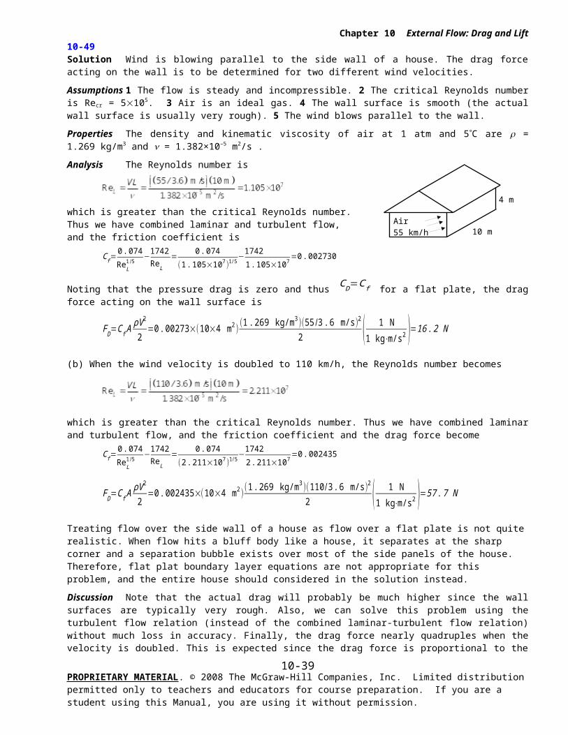
Air60F, 20 mph
Arm
WindV = 40 km/h
T = 15C
Transmission wire,D = 0.6 cmL = 120 m
Chapter 10 External Flow: Drag and Lift
10-64E Solution A person extends his uncovered arms into the windy air outside. The drag force exerted on both arms by the wind is to be determined.
Assumptions 1 The surfaces of the arms are smooth so that Fig. 10-34 can be used to determine the drag coefficient. 2 Air flow in the wind is steady and incompressible. 3 The turbulence in the wind is not considered. 4The direction of wind is normal to the arms. 5 The arms can be treated as 2-ft-long and 3-in.-diameter cylinders with negligible end effects.
Properties The density and kinematic viscosity of air at 1 atm and 60F are = 0.07633 lbm/ft3 and = 0.5718 ft2/h = 1.58810-4 ft2/s.
Analysis Noting that D = 3 in = 0.25 ft and 1 mph = 1.4667 ft/s, the Reynolds number for flow over the arm is
Re=VDν
=(20×1. 4667 ft/s )(0 . 25 ft )
1 . 588×10−4 ft2 /s=4 . 618×104
The drag coefficient corresponding to this value is, from Fig. 10-34, CD = 1.0. Also, the frontal area for flow past a cylinder is A = LD. Then the total drag force acting on both arms becomes
FD=CD AρV 2
2=1.0×(2×2×0 .25 ft2)
(0 .07633 lbm/ft3 )(20×1 .4667 ft/s )2
2 ( 1 lbf32 .2 lbm⋅ft/s2 )=1 .02 lbf
Discussion Note that this force is equivalent to the weight of 1 lbm mass. Therefore, the drag force the wind exerts on the arms of this person is equivalent to hanging 0.5 lbm of mass on each arm. Also, it should be kept in mind that the wind turbulence and the surface roughness may affect the calculated result significantly.
10-65 Solution Wind is blowing across the wire of a transmission line. The drag force exerted on the wire by the wind is to be determined.
Assumptions 1 The wire surfaces are smooth so that Fig. 10-34 can be used to determine the drag coefficient. 2 Air flow in the wind is steady and incompressible. 3 The turbulence in the wind is not considered. 4The direction of wind is normal to the wire.
Properties The density and kinematic viscosity of air at 1 atm and 15C are = 1.225 kg/m3 and = 1.47010-5 m2/s.
Analysis Noting that D = 0.006 m and 1 m/s = 3.6 km/h, the Reynolds number for the flow is
Re=VDν
=( 40/3 .6 m/s )(0 .006 m )
1. 470×10−5 m2 /s=4 . 535×103
The drag coefficient corresponding to this value is, from Fig. 10-34, CD = 1.0. Also, the frontal area for flow past a cylinder is A = LD. Then the drag force becomes
FD=CD AρV 2
2=1. 0(120×0 .006 m2 )
(1 .225 kg/m3 )(40/3 . 6 m/s )2
2 ( 1 N1 kg⋅m/s2 )=54 . 4 N
Therefore, the drag force acting on the wire is 54.4 N, which is equivalent to the weight of about 5.4 kg mass hanging on the wire.
Discussion It should be kept in mind that wind turbulence may reduce the drag coefficients by inducing turbulence and delaying flow separation.
PROPRIETARY MATERIAL. © 2008 The McGraw-Hill Companies, Inc. Limited distribution permitted only to teachers and educators for course preparation. If you are a student using this Manual, you are using it without permission.
10-39
AirT = 5C
HailD = 0.3 cm
D
Chapter 10 External Flow: Drag and Lift
10-66 Solution Spherical hail is falling freely in the atmosphere. The terminal velocity of the hail in air is to be determined.
Assumptions 1 The surface of the hail is smooth so that Fig. 10-34 can be used to determine the drag coefficient. 2 The variation of the air properties with altitude is negligible. 3 The buoyancy force applied by air to hail is negligible since air
<< hail (besides, the uncertainty in the density of hail is greater than the density of air). 4 Air flow over the hail is steady and incompressible when terminal velocity is established. 5 The atmosphere is calm (no winds or drafts).
Properties The density and kinematic viscosity of air at 1 atm and 5C are = 1.269 kg/m3 and = 1.38210-5 m2/s. The density of hail is given to be 910 kg/m3.
Analysis The terminal velocity of a free falling object is reached when the drag force equals the weight of the solid object less the buoyancy force applied by the fluid, which is negligible in this case,
FD=W−FB where FD=CD A
ρ f V 2
2, W=mg= ρs gV= ρs g( πD3 /6 ) , and FB≃0
and A = D2/4 is the frontal area. Substituting and simplifying,
CD Aρf V 2
2=W → CD
πD2
4
ρf V 2
2=ρ s g
πD3
6 → CD ρf V 2= ρs g
4 D3
Solving for V and substituting,
V=√ 4 gρ s D
3CD ρ f
=√ 4(9 .81 m/s2)( 910 kg/m3)(0 .008 m)3CD(1 .269 kg/m3)
→ V =8 . 662
√CD (1)
The drag coefficient CD is to be determined from Fig. 10-34, but it requires the Reynolds number which cannot be calculated since we do not know velocity. Therefore, the solution requires a trial-error approach. First we express the Reynolds number as
Re=VDν
=V (0. 008 m )
1. 382×10−5 m2 /s → Re=578 . 9 V
(2)
Now we choose a velocity in m/s, calculate the Re from Eq. 2, read the corresponding CD from Fig. 10-34, and calculate V from Eq. 1. Repeat calculations until the assumed velocity matches the calculated velocity. With this approach the terminal velocity is determined to be
V = 13.7 m/s
The corresponding Re and CD values are Re = 7930 and CD = 0.40. Therefore, the velocity of hail will remain constant when it reaches the terminal velocity of 13.7 m/s = 49 km/h.
Discussion The simple analysis above gives us a reasonable value for the terminal velocity. A more accurate answer can be obtained by a more detailed (and complex) analysis by considering the variation of air properties with altitude, and by considering the uncertainty in the drag coefficient (a hail is not necessarily spherical and smooth).
PROPRIETARY MATERIAL. © 2008 The McGraw-Hill Companies, Inc. Limited distribution permitted only to teachers and educators for course preparation. If you are a student using this Manual, you are using it without permission.
10-40
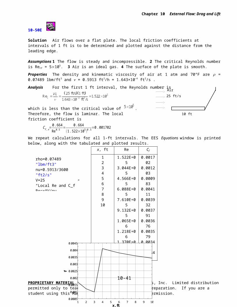
Chapter 10 External Flow: Drag and Lift
10-67 Solution A spherical dust particle is suspended in the air at a fixed point as a result of an updraft air motion. The magnitude of the updraft velocity is to be determined using Stokes law.
Assumptions 1 The Reynolds number is low (at the order of 1) so that Stokes law is applicable (to be verified). 2 The updraft is steady and incompressible. 3 The buoyancy force applied by air to the dust particle is negligible since air << dust
(besides, the uncertainty in the density of dust is greater than the density of air). (We will solve the problem without utilizing this assumption for generality).
Properties The density of dust is given to be s = 2.1 g/cm3 = 2100 kg/m3. The density and dynamic viscosity of air at 1 atm and 25C are f = 1.184 kg/m3 and m = 1.84910-5 kg/m×s.
Analysis The terminal velocity of a free falling object is reached (or the suspension of an object in a flow stream is established) when the drag force equals the weight of the solid object less the buoyancy force applied by the surrounding fluid,
FD=W−FB where
FD=3 πμVD (Stokes law),
W=ρs gV , and FB= ρf gV
Here V = D3/6 is the volume of the sphere. Substituting,
3 πμVD=ρs gV −ρf gV → 3 πμ VD=( ρ s−ρf )gπD3
6
Solving for the velocity V and substituting the numerical values, the updraft velocity is determined to be
V =gD2 ( ρs−ρ f )18 μ
=(9 .81 m/s2 )(0 .0001 m )2 (2100-1 .184 ) kg/m3
18(1. 849×10-5 kg/m⋅s )=0. 619 m/s
The Reynolds number in this case is
Re= ρVDμ
=(1 .184 kg/m3 )(0. 619 m/s )(0 .0001 m )
1 . 849×10-5 kg⋅m/s=4 . 0
which is in the order of 1. Therefore, the creeping flow idealization and thus Stokes law is applicable, and the value calculated is valid.
Discussion Flow separation starts at about Re = 10. Therefore, Stokes law can be used as an approximation for Reynolds numbers up to this value, but this should be done with care.
PROPRIETARY MATERIAL. © 2008 The McGraw-Hill Companies, Inc. Limited distribution permitted only to teachers and educators for course preparation. If you are a student using this Manual, you are using it without permission.
0.1 V
Ai
Du
10-41
0.05 mmV
Dust
Chapter 10 External Flow: Drag and Lift
10-68 Solution Dust particles that are unsettled during high winds rise to a specified height, and start falling back when things calm down. The time it takes for the dust particles to fall back to the ground and their velocity are to be determined using Stokes law.
Assumptions 1 The Reynolds number is low (at the order of 1) so that Stokes law is applicable (to be verified). 2 The atmosphere is calm during fall back (no winds or drafts). 3 The initial transient period during which the dust particle accelerates to its terminal velocity is negligible. 4 The buoyancy force applied by air to the dust particle is negligible since air << dust (besides, the uncertainty in the density of dust is greater than the density of air). (We will solve this problem without utilizing this assumption for generality).
Properties The density of dust is given to be s = 1.8 g/cm3 = 1800 kg/m3. The density and dynamic viscosity of air at 1 atm and 15C are f = 1.225 kg/m3 and m = 1.80210-5 kg/m×s.
Analysis The terminal velocity of a free falling object is reached when the drag force equals the weight of the solid object less the buoyancy force applied by the surrounding fluid,
FD=W−FB where
FD=3 πμVD (Stokes law),
W=ρs gV , and FB= ρf gV
Here V = D3/6 is the volume of the sphere. Substituting,
3 πμVD=ρs gV −ρf gV → 3 πμ VD=( ρ s−ρf )gπD3
6
Solving for the velocity V and substituting the numerical values, the terminal velocity is determined to be
V=gD2( ρ s− ρf )18 μ
=(9 .81 m/s2 )(5×10⁻⁵ m )2(1800-1 .225 ) kg/m3
18 (1 . 802×10-5 kg/m⋅s )=0 . 136 m/s
Then the time it takes for the dust particle to travel 350 m at this velocity becomes
Δt= LV=350 m
0 .136 m/s=2573 s =42 . 9 min
The Reynolds number is
Re= ρVDμ
=(1 .225 kg/m3 )(0. 136 m/s )(5×10⁻⁵ m )
1 .802×10-5 kg⋅m/s=0 . 46
which is in the order of 1. Therefore, the creeping flow idealization and thus Stokes law is applicable.
Discussion Note that the dust particle reaches a terminal velocity of 0.136 m/s, and it takes about an hour to fall back to the ground. The presence of drafts in air may significantly increase the settling time.
PROPRIETARY MATERIAL. © 2008 The McGraw-Hill Companies, Inc. Limited distribution permitted only to teachers and educators for course preparation. If you are a student using this Manual, you are using it without permission.
10-42
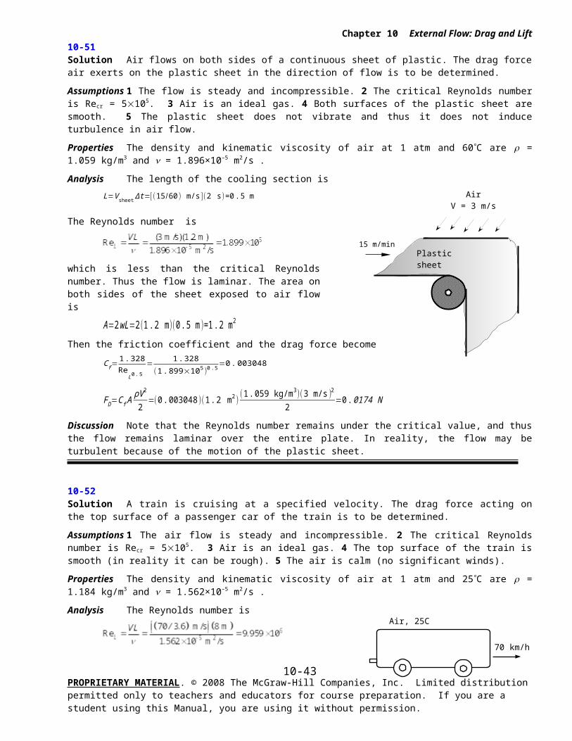
80 km/h
2 m
0.2 m
Chapter 10 External Flow: Drag and Lift
10-69 [Also solved using EES on enclosed DVD]
Solution A cylindrical log suspended by a crane is subjected to normal winds. The angular displacement of the log and the tension on the cable are to be determined.
Assumptions 1 The surfaces of the log are smooth so that Fig. 10-34 can be used to determine the drag coefficient (not a realistic assumption). 2 Air flow in the wind is steady and incompressible. 3 The turbulence in the wind is not considered. 4The direction of wind is normal to the log, which always remains horizontal. 5 The end effects of the log are negligible. 6 The weight of the cable and the drag acting on it are negligible. 7 Air is an ideal gas.
Properties The dynamic viscosity of air at 5C (independent of pressure) is m = 1.75410-5 kg/m×s. Then the density and kinematic viscosity of air are calculated to be
ρ= PRT
=88 kPa
( 0.287 kPa⋅m3 /kg⋅K )(278 K )=1 .103 kg/m3
ν=μρ=1 .754×10−5 kg/m⋅s
1 .103 kg/m3=1 .590×10−5 m2 /s
Analysis Noting that D = 0.2 m and 1 m/s = 3.6 km/h, the Reynolds number is
Re=VDν
=( 40/3 .6 m/s )(0 .2 m )
1. 590×10−5 m2 /s=1. 398×105
The drag coefficient corresponding to this value is, from Fig. 10-34, CD = 1.2. Also, the frontal area for flow past a cylinder is A = LD. Then the total drag force acting on the log becomes
FD=CD AρV 2
2=1. 2(2×0 . 2 m2 )
(1.103 kg/m3 )(40 /3 . 6 m/s )2
2 ( 1 N1 kg⋅m/s2 )=32 . 7 N
The weight of the log is
W=mg=ρgV =ρgπD2 L
4=(513 kg/m3 )(9 . 81 m/s2)
π (0 .2 m )2(2 m )4 ( 1 N
1 kg⋅m/s2 )=316 N
Then the resultant force acting on the log and the angle it makes with the horizontal become
F log=R=√W 2+F D2 =√32. 72+3162=318 N
tanθ=WFD
=31632 .7
=9 .66 → θ=84°
Drawing a free body diagram of the log and doing a force balance will show that the magnitude of the tension on the cable must be equal to the resultant force acting on the log. Therefore, the tension on the cable is 318 N and the cable makes 84 with the horizontal.
Discussion Note that the wind in this case has rotated the cable by 6 from its vertical position, and increased the tension action on it somewhat. At very high wind speeds, the increase in the cable tension can be very significant, and wind loading must always be considered in bodies exposed to high winds.
PROPRIETARY MATERIAL. © 2008 The McGraw-Hill Companies, Inc. Limited distribution permitted only to teachers and educators for course preparation. If you are a student using this Manual, you are using it without permission.
10-43
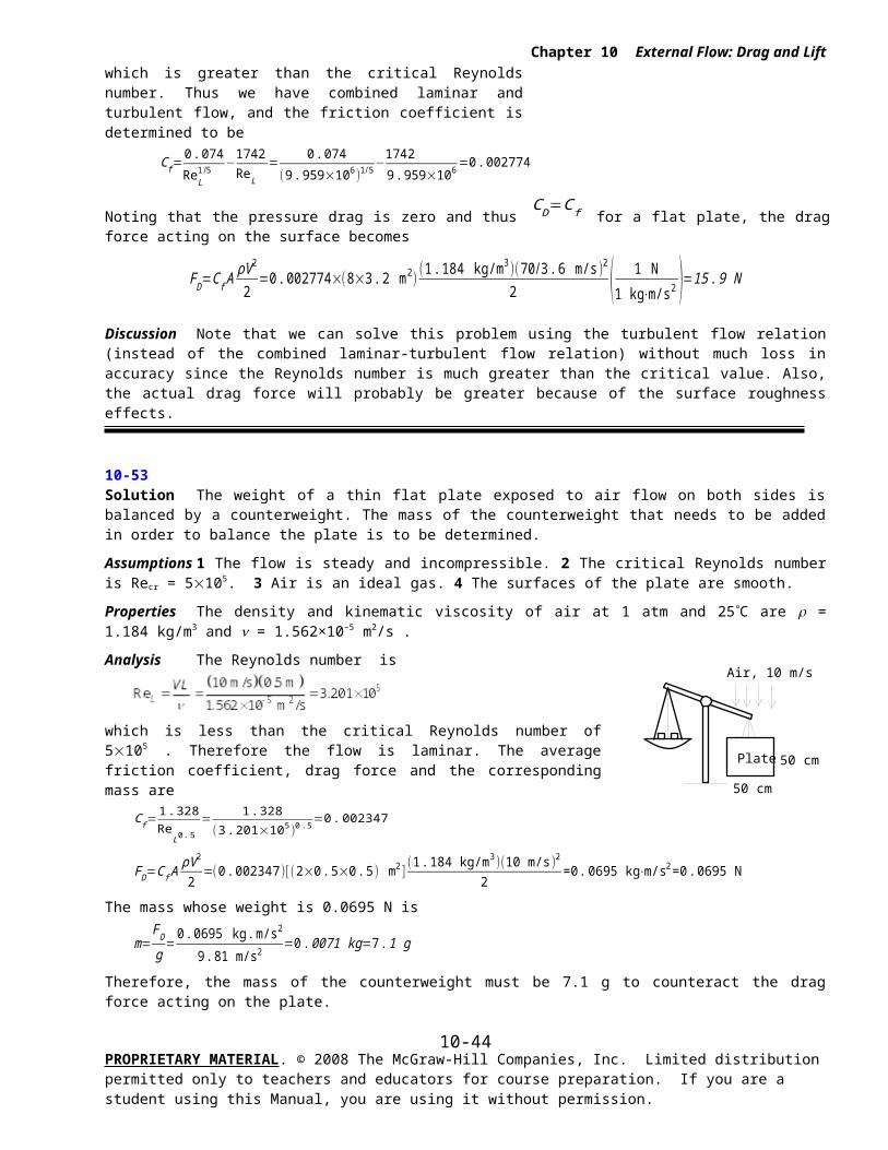
Air jet
Ball2.6 g
Chapter 10 External Flow: Drag and Lift
10-70 Solution A ping-pong ball is suspended in air by an upward air jet. The velocity of the air jet is to be determined, and the phenomenon that the ball returns to the center of the air jet after a disturbance is to be explained.
Assumptions 1 The surface of the ping-pong ball is smooth so that Fig. 10-34 can be used to determine the drag coefficient. 2 Air flow over the ball is steady and incompressible.
Properties The density and kinematic viscosity of air at 1 atm and 25C are = 1.184 kg/m3 and = 1.56210-5 m2/s.
Analysis The terminal velocity of a free falling object is reached when the drag force equals the weight of the solid object less the buoyancy force applied by the fluid,
FD=W−FB where FD=CD A
ρ f V 2
2, W=mg , and FB=ρ f gV
Here A = D2/4 is the frontal area and V = D3/6 is the volume of the sphere. Also,
W=mg=(0 .0026 kg )(9 .81 m/s2 )=0 .0255 kg⋅m/s2=0 .0255 N
FB=ρ f gπD3
6=(1 .184 kg/m3 )(9 .81 m/s2 )
π (0 . 038 m )3
6=0 .000334 kg⋅m/s2=0 .000334 N
Substituting and solving for V,
CDπD2
4
ρf V 2
2=W−FB → V =√ 8 (W−FB )
πD2CD ρ f
=√ 8(0 . 0255−0. 000334 ) kg⋅m/s2 )π ( 0. 038 m)2CD (1 . 184 kg/m3 )
→ V=6 . 122
√C D (1)
The drag coefficient CD is to be determined from Fig. 10-34, but it requires the Reynolds number which cannot be calculated since we do not know velocity. Therefore, the solution requires a trial-error approach. First we express the Reynolds number as
Re=VDν
=V (0. 038 m )
1. 562×10−5 m 2 /s → Re=2433 V
(2)
Now we choose a velocity in m/s, calculate the Re from Eq. 2, read the corresponding CD from Fig. 10-34, and calculate V from Eq. 1. Repeat calculations until the assumed velocity matches the calculated velocity. With this approach the velocity of the fluid jet is determined to be
V = 9.3 m/s
The corresponding Re and CD values are Re = 22,600 and CD = 0.43. Therefore, the ping-pong ball will remain suspended in the air jet when the air velocity reaches 9.3 m/s = 33.5 km/h.
Discussion
1 If the ball is pushed to the side by a finger, the ball will come back to the center of the jet (instead of falling off) due to the Bernoulli effect. In the core of the jet the velocity is higher, and thus the pressure is lower relative to a location away from the jet.
2 Note that this simple apparatus can be used to determine the drag coefficients of certain object by simply measuring the air velocity, which is easy to do.
3 This problem can also be solved roughly by taking CD = 0.5 from Table 10-2 for a sphere in laminar flow, and then verifying that the flow is laminar.
PROPRIETARY MATERIAL. © 2008 The McGraw-Hill Companies, Inc. Limited distribution permitted only to teachers and educators for course preparation. If you are a student using this Manual, you are using it without permission.
10-44
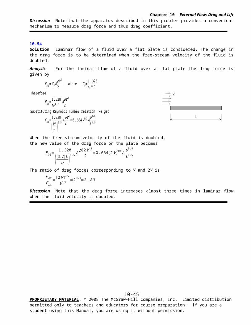
Chapter 10 External Flow: Drag and Lift
Lift
10-71C Solution We are to discuss why the contribution of viscous effects to lift of airfoils is usually negligible.
Analysis The contribution of viscous effects to lift is usually negligible for airfoils since the wall shear is nearly parallel to the surfaces of such devices and thus nearly normal to the direction of lift.
Discussion However, viscous effects are extremely important for airfoils at high angles of attack, since the viscous effects near the wall (in the boundary layer) cause the flow to separate and the airfoil to stall, losing significant lift.
10-72C Solution We are to discuss the lift and drag on a symmetrical airfoil at zero angle of attack.
Analysis When air flows past a symmetrical airfoil at zero angle of attack, (a) the lift is zero, but (b) the drag acting on the airfoil is nonzero.
Discussion In this case, because of symmetry, there is no lift, but there is still skin friction drag, along with a small amount of pressure drag.
10-73C Solution We are to discuss the lift and drag on a nonsymmetrical airfoil at zero angle of attack.
Analysis When air flows past a nonsymmetrical airfoil at zero angle of attack, both the (a) lift and (b) drag acting on the airfoil are nonzero.
Discussion Because of the lack of symmetry, the flow is different on the top and bottom surfaces of the airfoil, leading to lift. There is drag too, just as there is drag even on a symmetrical airfoil.
10-74C Solution We are to discuss the lift and drag on a symmetrical airfoil at 5o angle of attack.
Analysis When air flows past a symmetrical airfoil at an angle of attack of 5, both the (a) lift and (b) drag acting on the airfoil are nonzero.
Discussion Because of the lack of symmetry with respect to the free-stream flow, the flow is different on the top and bottom surfaces of the airfoil, leading to lift. There is drag too, just as there is drag even at zero angle of attack.
10-75C Solution We are to define and discuss stall.
Analysis The decrease of lift with an increase in the angle of attack is called stall. When the flow separates over nearly the entire upper half of the airfoil, the lift is reduced dramatically (the separation point is near the leading edge). Stall is caused by flow separation and the formation of a wide wake region over the top surface of the airfoil . Commercial aircraft are not allowed to fly at velocities near the stall velocity for safety reasons. Airfoils stall at high angles of attack (flow cannot negotiate the curve around the leading edge). If a plane stalls, it loses mush of its lift, and it can crash.
Discussion At angles of attack above the stall angle, the drag also increases significantly.
PROPRIETARY MATERIAL. © 2008 The McGraw-Hill Companies, Inc. Limited distribution permitted only to teachers and educators for course preparation. If you are a student using this Manual, you are using it without permission.
10-45
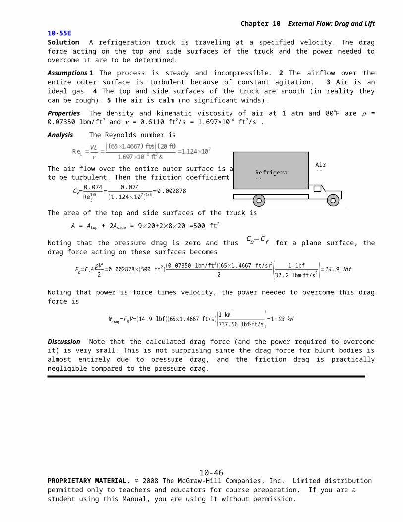
Chapter 10 External Flow: Drag and Lift
10-76C Solution We are to discuss which increases at a greater rate – lift or drag – with increasing angle of attack.
Analysis Both the lift and the drag of an airfoil increase with an increase in the angle of attack, but in general, the lift increases at a much higher rate than does the drag.
Discussion In other words, the lift-to-drag ratio increases with increasing angle of attack – at least up to the stall angle.
10-77C Solution We are to why flaps are used on aircraft during takeoff and landing.
Analysis Flaps are used at the leading and trailing edges of the wings of large aircraft during takeoff and landing to alter the shape of the wings to maximize lift and to enable the aircraft to land or takeoff at low speeds. An aircraft can take off or land without flaps, but it can do so at very high velocities, which is undesirable during takeoff and landing.
Discussion In simple terms, the planform area of the wing increases as the flaps are deployed. Thus, even if the lift coefficient were to remain constant, the actual lift would still increase. In fact, however, flaps increase the lift coefficient as well, leading to even further increases in lift. Lower takeoff and landing speeds lead to shorter runway length requirements.
10-78C Solution We are to discuss how flaps affect the lift and drag of airplane wings.
Analysis Flaps increase both the lift and the drag of the wings. But the increase in drag during takeoff and landing is not much of a concern because of the relatively short time periods involved. This is the penalty we pay willingly to take off and land at safe speeds.
Discussion Note, however, that the engine must operate at nearly full power during takeoff to overcome the large drag.
10-79C Solution We are to discuss the effect of wing tip vortices on drag and lift.
Analysis The effect of wing tip vortices is to increase drag (induced drag) and to decrease lift. This effect is also due to the downwash, which causes an effectively smaller angle of attack.
Discussion Induced drag is a three-dimensional effect; there is no induced drag on a 2-D airfoil since there are no tips.
10-80C Solution We are to discuss induced drag and how to minimize it.
Analysis Induced drag is the additional drag caused by the tip vortices. The tip vortices have a lot of kinetic energy, all of which is wasted and is ultimately dissipated as heat in the air downstream. Induced drag can be reduced by using long and narrow wings, and by modifying the geometry of the wing tips.
Discussion Birds are designed with feathers that fan out at the tips of their wings in order to reduce induced drag.
10-81C Solution We are to explain why some airplane wings have endplates or winglets.
Analysis Endplates or winglets are added at the tips of airplane wings to reduce induced drag. In short, the winglets disrupt flow from the high pressure lower part of the wing to the low pressure upper part of the wing, thereby reducing the strength of the tip vortices.
Discussion Comparing a wing with and without winglets, the one with winglets can produce the same lift with less drag, thereby saving fuel or increasing range. Winglets are especially useful in glider planes because high lift with small drag is critical to their operation (and safety!).
PROPRIETARY MATERIAL. © 2008 The McGraw-Hill Companies, Inc. Limited distribution permitted only to teachers and educators for course preparation. If you are a student using this Manual, you are using it without permission.
10-46
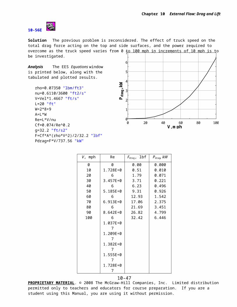
V = 550 mphm = 150,000 lbmAwing = 1800 m2
Chapter 10 External Flow: Drag and Lift
10-82E [Also solved using EES on enclosed DVD]
Solution Cruising conditions of a passenger plane are given. The minimum safe landing and takeoff speeds with and without flaps, the angle of attack during cruising, and the power required are to be determined
Assumptions 1 The drag and lift produced by parts of the plane other than the wings are not considered. 2 The wings are assumed to be two-dimensional airfoil sections, and the tip effects are neglected. 4 The lift and drag characteristics of the wings can be approximated by NACA 23012 so that Fig. 10-45 is applicable.
Properties The densities of air are 0.075 lbm/ft3 on the ground and 0.0208 lbm/ft3 at cruising altitude. The maximum lift coefficients of the wings are 3.48 and 1.52 with and without flaps, respectively (Fig. 10-45).
Analysis (a) The weight and cruising speed of the airplane are
W=mg=(150 ,000 lbm )(32. 2 ft/s2 )( 1 lbf
32 .2 lbm⋅ft/s2 )=150 ,000 lbf
V=(550 mph )( 1. 4667 ft/s1 mph )=806.7 ft/s
Minimum velocity corresponding the stall conditions with and without flaps are
V min 1=√ 2W
ρC L ,max1 A=√ 2(150 ,000 lbf )
(0 . 075 lbm/ft3 )(1 .52 )(1800 ft2 )(32 . 2 lbm⋅ft/s2
1 lbf )=217 ft/s
V min 2=√ 2 W
ρC L ,max2 A==√ 2(150 , 000 lbf )
(0 .075 lbm/ft3)(3 .48 )(1800 ft2 )(32 .2 lbm⋅ft/s2
1 lbf )=143 ft/s
The “safe” minimum velocities to avoid the stall region are obtained by multiplying these values by 1.2:
Without flaps: V min 1 , safe=1. 2V min 1=1. 2×(217 ft/s )=260 ft/s = 178 mph
With flaps: V min 2, safe=1. 2V min 2=1.2×(143 ft/s )=172 ft/s =117 mph
since 1 mph = 1.4667 ft/s. Note that the use of flaps allows the plane to takeoff and land at considerably lower velocities, and thus at a shorter runway.
(b) When an aircraft is cruising steadily at a constant altitude, the lift must be equal to the weight of the aircraft, FL = W. Then the lift coefficient is determined to be
CL=F L
12
ρV2 A=150 ,000 lbf
12(0 . 0208 lbm/ft3 )(806 .7 ft/s )2 (1800 ft2 )(32 .2 lbm⋅ft/s2
1 lbf )=0 .40
For the case of no flaps, the angle of attack corresponding to this value of CL is determined from Fig. 10-45 to be about = 3.5.
(c) When aircraft cruises steadily, the net force acting on the aircraft is zero, and thus thrust provided by the engines must be equal to the drag force. The drag coefficient corresponding to the cruising lift coefficient of 0.40 is CD = 0.015 (Fig. 10-45). Then the drag force acting on the wings becomes
FD=CD AρV 2
2=(0 .015)(1800 ft2 )
(0 .0208 lbm/ft3 )(806 .7 ft/s )2
2 ( 1 lbf32 .2 lbm⋅ft/s2 )=5675 lbf
Noting that power is force times velocity (distance per unit time), the power required to overcome this drag is equal to the thrust times the cruising velocity,
Power=Thrust×Velocity=F D V=(5675 lbf )(806 .7 ft/s)(1 kW737 .56 lbf⋅ft/s )=6200 kW
Discussion Note that the engines must supply 6200 kW of power to overcome the drag during cruising. This is the power required to overcome the drag that acts on the wings only, and does not include the drag that acts on the remaining parts of the aircraft (the fuselage, the tail, etc).
PROPRIETARY MATERIAL. © 2008 The McGraw-Hill Companies, Inc. Limited distribution permitted only to teachers and educators for course preparation. If you are a student using this Manual, you are using it without permission.
10-47
TakeoffV = 190 km/h
Chapter 10 External Flow: Drag and Lift
10-83
Solution The takeoff speed of an aircraft when it is fully loaded is given. The required takeoff speed when the weight of the aircraft is increased by 20% as a result of overloading is to be determined.
Assumptions 1 The atmospheric conditions (and thus the properties of air) remain the same. 2 The settings of the plane during takeoff are maintained the same so that the lift coefficient of the plane remains the same.
Analysis An aircraft will takeoff when lift equals the total weight. Therefore,
W=FL → W= 12
C L ρV2 A → V =√ 2 WρC L A
We note that the takeoff velocity is proportional to the square root of the weight of the aircraft. When the density, lift coefficient, and area remain constant, the ratio of the velocities of the overloaded and fully loaded aircraft becomes
V 2
V 1
=√2W 2/ ρCL A
√2W 1 / ρCL A=√W 2
√W 1
→ V 2=V 1√W 2
W 1
Substituting, the takeoff velocity of the overloaded aircraft is determined to be
V 2=V 1√ 1 .2W 1
W 1
=(190 km/h )√1 .2=208 km/h
Discussion A similar analysis can be performed for the effect of the variations in density, lift coefficient, and planform area on the takeoff velocity.
PROPRIETARY MATERIAL. © 2008 The McGraw-Hill Companies, Inc. Limited distribution permitted only to teachers and educators for course preparation. If you are a student using this Manual, you are using it without permission.
10-48
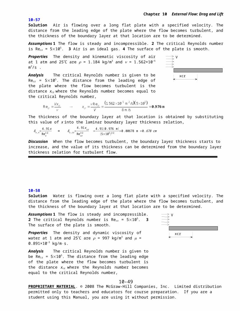
Cruisingmfuel = 5 gal/min
Chapter 10 External Flow: Drag and Lift
10-84E Solution The rate of fuel consumption of an aircraft while flying at a low altitude is given. The rate of fuel consumption at a higher altitude is to be determined for the same flight velocity.
Assumptions 1 Standard atmospheric conditions exist. 2 The settings of the plane during takeoff are maintained the same so that the drag coefficient of the plane and the planform area remain constant. 3 The velocity of the aircraft and the propulsive efficiency remain constant. 4 The fuel is used primarily to provide propulsive power to overcome drag, and thus the energy consumed by auxiliary equipment (lights, etc) is negligible.
Properties The density of standard air is 1 = 0.05648 lbm/ft3 at 10,000 ft, and 2 = 0.02866 lbm/ft3 at 30,000 ft altitude.
Analysis When an aircraft cruises steadily (zero acceleration) at a constant altitude, the net force acting on the aircraft is zero, and thus the thrust provided by the engines must be equal to the drag force. Also, power is force times velocity (distance per unit time), and thus the propulsive power required to overcome drag is equal to the thrust times the cruising velocity. Therefore,
W propulsive=Thrust×V=FD V=CD AρV 2
2V=CD A
ρV 3
2
The propulsive power is also equal to the product of the rate of fuel energy supplied (which is the rate of fuel consumption times the heating value of the
fuel, mfuel HV ) and the propulsive efficiency. Then,
W prop=ηpropmfuel HV → CD AρV 3
2=ηprop mfuel HV
We note that the rate of fuel consumption is proportional to the density of air. When the drag coefficient, the wing area, the velocity, and the propulsive efficiency remain constant, the ratio of the rates of fuel consumptions of the aircraft at high and low altitudes becomes
mfuel, 2
mfuel, 1
=C D Aρ2 V 3 /2ηprop HV
CD Aρ1 V 3 /2ηprop HV=
ρ2
ρ1
→ { mfuel, 2
=mfuel, 1
ρ2
ρ1
=(5 gal/min) 0. 028660 .05648
=2. 54 gal/min ¿
Discussion Note the fuel consumption drops by half when the aircraft flies at 30,000 ft instead of 10,000 ft altitude. Therefore, large passenger planes routinely fly at high altitudes (usually between 30,000 and 40,000 ft) to save fuel. This is especially the case for long flights.
PROPRIETARY MATERIAL. © 2008 The McGraw-Hill Companies, Inc. Limited distribution permitted only to teachers and educators for course preparation. If you are a student using this Manual, you are using it without permission.
10-49

TakeoffV = 250 km/h
0 100 200 300 400 500225
230
235
240
245
250
Nempty seats
V,
m/s
Chapter 10 External Flow: Drag and Lift
10-85 Solution The takeoff speed of an aircraft when it is fully loaded is given. The required takeoff speed when the aircraft has 100 empty seats is to be determined.
Assumptions 1 The atmospheric conditions (and thus the properties of air) remain the same. 2 The settings of the plane during takeoff are maintained the same so that the lift coefficient of the plane remains the same. 3 A passenger with luggage has an average mass of 140 kg.
Analysis An aircraft will takeoff when lift equals the total weight. Therefore,
W=FL → W= 12C L ρV2 A → V =√ 2W
ρCL A
We note that the takeoff velocity is proportional to the square root of the weight of the aircraft. When the density, lift coefficient, and wing area remain constant, the ratio of the velocities of the under-loaded and fully loaded aircraft becomes
V 2
V 1
=√2W 2/ ρCL A
√2W 1 / ρCL A=√W 2
√W 1
=√m2 g
√m1 g=√m2
√m1
→ V 2=V 1√ m2
m1
where m2=m1−munused capacity=400 ,000 kg−(140 kg/passanger )×(100 passengers)=386 , 000 kg
Substituting, the takeoff velocity of the overloaded aircraft is determined to be
V 2=V 1√m2
m1
=(250 km/h )√386,000400,000
=246 km/h
Discussion Note that the effect of empty seats on the takeoff velocity of the aircraft is small. This is because the most weight of the aircraft is due to its empty weight (the aircraft itself rather than the passengers and their luggage.)
10-86
Solution The previous problem is reconsidered. The effect of empty passenger count on the takeoff speed of the aircraft as the number of empty seats varies from 0 to 500 in increments of 50 is to be investigated.
Analysis The EES Equations window is printed below, along with the tabulated and plotted results.
m_passenger=140 "kg"m1=400000 "kg"m2=m1-N_empty*m_passengerV1=250 "km/h"V2=V1*SQRT(m2/m1)
Empty seats
mairplane,1, kg
mairplane,1, kg
Vtakeoff,
m/s
050100150200250300350400450500
400000400000400000400000400000400000400000400000400000400000400000
400000393000386000379000372000365000358000351000344000337000330000
250.0247.8245.6243.3241.1238.8236.5234.2231.8229.5227.1
Discussion As expected, the takeoff speed decreases as the number of empty seats increases. On the scale plotted, the curve appears nearly linear, but it is not; the curve is actually a small portion of a square-root curve.
PROPRIETARY MATERIAL. © 2008 The McGraw-Hill Companies, Inc. Limited distribution permitted only to teachers and educators for course preparation. If you are a student using this Manual, you are using it without permission.
10-50
Chapter 10 External Flow: Drag and Lift
PROPRIETARY MATERIAL. © 2008 The McGraw-Hill Companies, Inc. Limited distribution permitted only to teachers and educators for course preparation. If you are a student using this Manual, you are using it without permission.
10-51
Awing=30 m2
2800 kg
CL=0.45
Chapter 10 External Flow: Drag and Lift
10-87 Solution The wing area, lift coefficient at takeoff settings, the cruising drag coefficient, and total mass of a small aircraft are given. The takeoff speed, the wing loading, and the required power to maintain a constant cruising speed are to be determined.
Assumptions 1 Standard atmospheric conditions exist. 2 The drag and lift produced by parts of the plane other than the wings are not considered.
Properties The density of standard air at sea level is = 1.225 kg/m3.
Analysis (a) An aircraft will takeoff when lift equals the total weight. Therefore,
W=FL → W= 12
C L ρV2 A → V =√ 2 WρC L A
Substituting, the takeoff speed is determined to be
V takeoff=√2mgρC L , takeoff A
=√2(2800 kg )(9 .81 m/s2 )(1.225 kg/m3 )(0 .45 )(30 m2 )
=57 .6 m/s=207 km/h
(b) Wing loading is the average lift per unit planform area, which is equivalent to the ratio of the lift to the planform area of the wings since the lift generated during steady cruising is equal to the weight of the aircraft. Therefore,
F loading=FL
A=W
A=(2800 kg )(9 .81 m/s2 )30 m2
=916 N/m2
(c) When the aircraft is cruising steadily at a constant altitude, the net force acting on the aircraft is zero, and thus thrust provided by the engines must be equal to the drag force, which is
FD=CD AρV 2
2=(0 . 035)(30 m2 )
(1 .225 kg/m3 )(300 /3 .6 m/s)2
2 ( 1 kN1000 kg⋅m/s2 )=4 . 466 kN
Noting that power is force times velocity, the propulsive power required to overcome this drag is equal to the thrust times the cruising velocity,
Power=Thrust×Velocity=F D V=( 4 . 466 kN)(300/3. 6 m/s )(1 kW1 kN⋅m/s )=372 kW
Therefore, the engines must supply 372 kW of propulsive power to overcome the drag during cruising.
Discussion The power determined above is the power to overcome the drag that acts on the wings only, and does not include the drag that acts on the remaining parts of the aircraft (the fuselage, the tail, etc). Therefore, the total power required during cruising will be greater. The required rate of energy input can be determined by dividing the propulsive power by the propulsive efficiency.
PROPRIETARY MATERIAL. © 2008 The McGraw-Hill Companies, Inc. Limited distribution permitted only to teachers and educators for course preparation. If you are a student using this Manual, you are using it without permission.
10-52
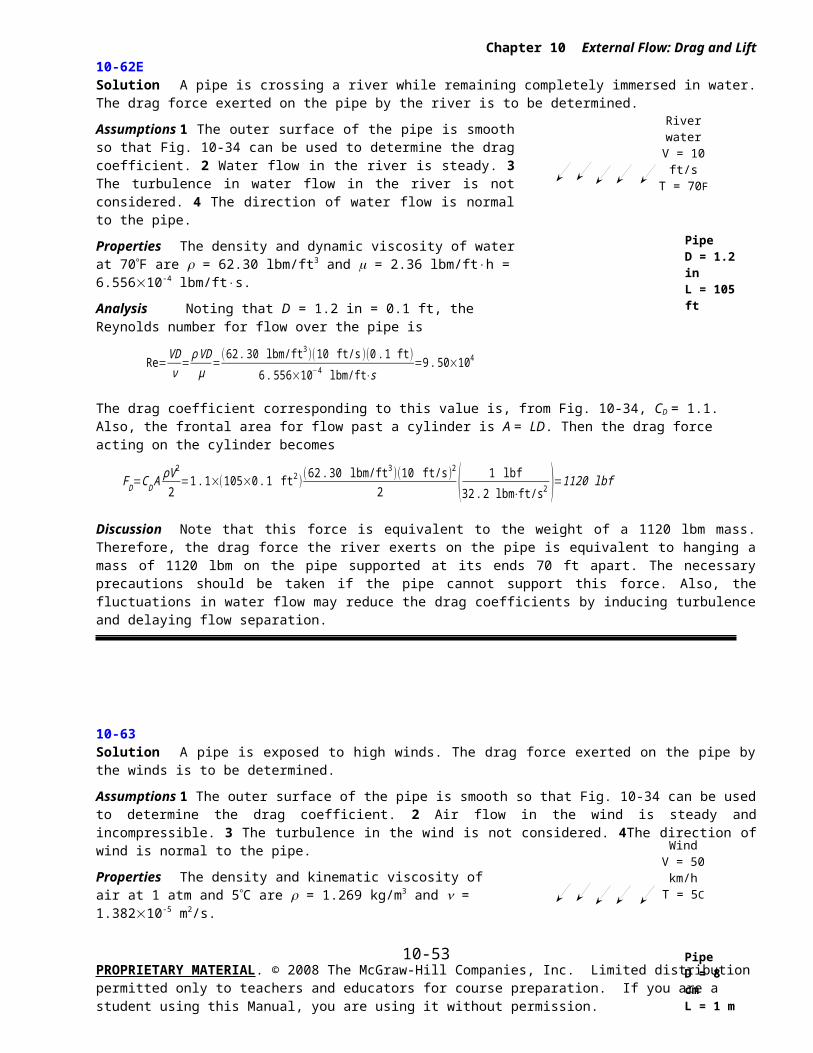
Awing=42 m2
1800 kg
280 km/h
Chapter 10 External Flow: Drag and Lift
10-88 Solution The total mass, wing area, cruising speed, and propulsive power of a small aircraft are given. The lift and drag coefficients of this airplane while cruising are to be determined.
Assumptions 1 Standard atmospheric conditions exist. 2 The drag and lift produced by parts of the plane other than the wings are not considered. 3 The fuel is used primarily to provide propulsive power to overcome drag, and thus the energy consumed by auxiliary equipment (lights, etc) is negligible.
Properties The density of standard air at an altitude of 4000 m is = 0.819 kg/m3.
Analysis Noting that power is force times velocity, the propulsive power required to overcome this drag is equal to the thrust times the cruising velocity. Also, when the aircraft is cruising steadily at a constant altitude, the net force acting on the aircraft is zero, and thus thrust provided by the engines must be equal to the drag force. Then,
W prop=Thrust×Velocity=FD V → FD=W prop
V=190 kW
280/3. 6 m/s (1000 N⋅m/s1 kW )=2443 N
Then the drag coefficient becomes
FD=CD AρV 2
2 → CD=
2 FD
ρ AV 2=
2(2443 N)(0 . 819 kg/m3 )(42 m2 )(280 /3 . 6 m/s)2 ( 1 kg⋅m/s2
1 N )=0 .0235
An aircraft cruises at constant altitude when lift equals the total weight. Therefore,
W=FL=12
C L ρV 2 A → C L=2 W
ρV 2 A=
2(1800 kg )(9 .81 m/s2 )(0 .819 kg/m3 )( 42 m2 )(280/3 .6 m/s )2
=0. 17
Therefore, the drag and lift coefficients of this aircraft during cruising are 0.0235 and 0.17, respectively, with a CL/CD ratio of 7.2.
Discussion The drag and lift coefficient determined are for cruising conditions. The values of these coefficient can be very different during takeoff because of the angle of attack and the wing geometry.
10-88 [second problem 10-88 – this was a typo error that was not caught in time for printing] Solution An airfoil has a given lift-to drag ratio at 0° angle of attack. The angle of attack that will raise this ratio to 80 is to be determined.
Analysis The ratio CL/CD for the given airfoil is plotted against the angle of attack in Fig. 10-43. The angle of attack corresponding to CL/CD = 80 is = 3.
Discussion Note that different airfoils have different CL/CD vs. charts.
PROPRIETARY MATERIAL. © 2008 The McGraw-Hill Companies, Inc. Limited distribution permitted only to teachers and educators for course preparation. If you are a student using this Manual, you are using it without permission.
10-53
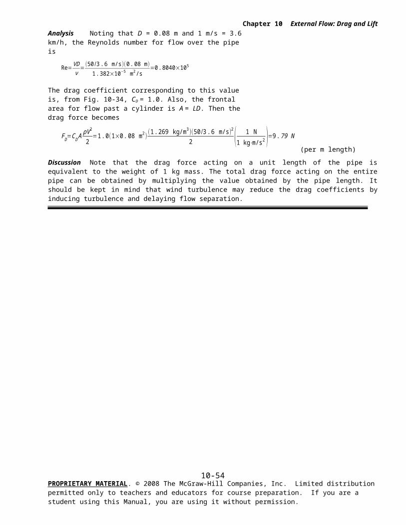
Awing= 46 m2
W = 15,000 N
Chapter 10 External Flow: Drag and Lift
10-89 Solution The wings of a light plane resemble the NACA 23012 airfoil with no flaps. Using data for that airfoil, the takeoff speed at a specified angle of attack and the stall speed are to be determined.
Assumptions 1 Standard atmospheric conditions exist. 2 The drag and lift produced by parts of the plane other than the wings are not considered.
Properties The density of standard air at sea level is = 1.225 kg/m3. At an angle of attack of 5°, the lift and drag coefficients are read from Fig. 10-45 to be CL = 0.6 and CD = 0.015. The maximum lift coefficient is CL,max = 1.52 and it occurs at an angle of attack of 15°.
Analysis An aircraft will takeoff when lift equals the total weight. Therefore,
W=FL → W= 12C L ρV2 A → V =√ 2W
ρCL A
Substituting, the takeoff speed is determined to be
V takeoff=√ 2(15 , 000 N)(1 .225 kg/m3)(0 . 6 )(46 m2 )( 1 kg⋅m/s2
1 N )=29 .8 m/s=107 km/h
since 1 m/s = 3.6 km/h. The stall velocity (the minimum takeoff velocity corresponding the stall conditions) is determined by using the maximum lift coefficient in the above equation,
V min=√ 2 WρCL ,max A
=√ 2(15 ,000 N)(1 . 225 kg/m3 )(1.52)( 46 m2 ) (1 kg⋅m/s2
1 N )=18 .7 m/s=67 .4 km/h
Discussion The “safe” minimum velocity to avoid the stall region is obtained by multiplying the stall velocity by 1.2:
V min, safe=1. 2V min=1 .2×(18 . 7 m/s )=22 . 4 m/s = 80 .8 km/h
Note that the takeoff velocity decreased from 107 km/h at an angle of attack of 5° to 80.8 km/s under stall conditions with a safety margin.
PROPRIETARY MATERIAL. © 2008 The McGraw-Hill Companies, Inc. Limited distribution permitted only to teachers and educators for course preparation. If you are a student using this Manual, you are using it without permission.
10-54
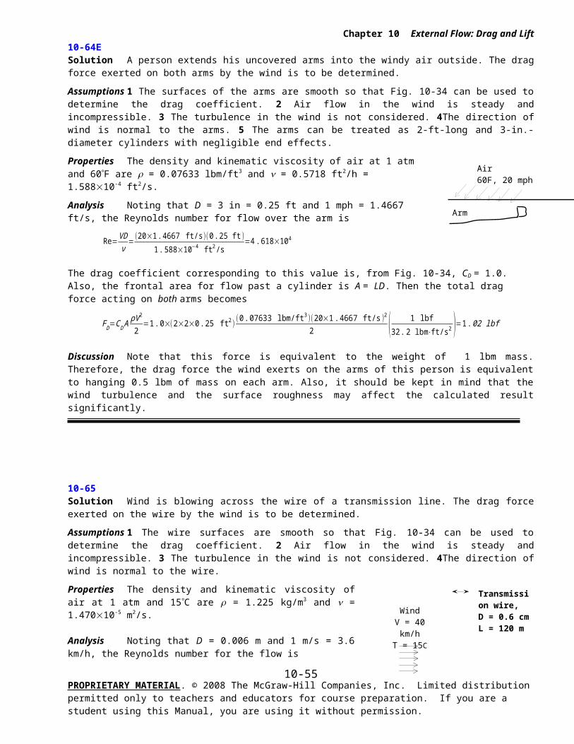
Awing=300 m2
m = 50,000 kg
FL = 3.2
Chapter 10 External Flow: Drag and Lift
10-90 [Also solved using EES on enclosed DVD]
Solution The mass, wing area, the maximum (stall) lift coefficient, the cruising speed and the cruising drag coefficient of an airplane are given. The safe takeoff speed at sea level and the thrust that the engines must deliver during cruising are to be determined.
Assumptions 1 Standard atmospheric conditions exist 2 The drag and lift produced by parts of the plane other than the wings are not considered. 3 The takeoff speed is 20% over the stall speed. 4 The fuel is used primarily to provide propulsive power to overcome drag, and thus the energy consumed by auxiliary equipment (lights, etc) is negligible.
Properties The density of standard air is 1 = 1.225 kg/m3 at sea level, and 2 = 0.312 kg/m3 at 12,000 m altitude. The cruising drag coefficient is given to be CD = 0.03. The maximum lift coefficient is given to be CL,max = 3.2.
Analysis (a) An aircraft will takeoff when lift equals the total weight. Therefore,
W=FL → W= 12
C L ρV2 A → V =√ 2 WρC L A
=√ 2 mgρC L A
The stall velocity (the minimum takeoff velocity corresponding the stall conditions) is determined by using the maximum lift coefficient in the above equation,
V min=√ 2mgρ1 C L ,max A
=√ 2(50 ,000 kg )(9 .81 m/s2 )(1.225 kg/m3 )(3 .2 )(300 m2 )
=28 .9 m/s=104 km/h
since 1 m/s = 3.6 km/h. Then the “safe” minimum velocity to avoid the stall region becomes
V min, safe=1. 2V min=1 .2×(28 .9 m/s )=34 .7 m/s =125 km/h
(b) When the aircraft cruises steadily at a constant altitude, the net force acting on the aircraft is zero, and thus the thrust provided by the engines must be equal to the drag force, which is
FD=CD Aρ2V 2
2=(0 . 03 )(300 m2 )
(0. 312 kg/m3 )(700/3 .6 m/s )2
2 ( 1 kN
1000 kg⋅m/s2 )=53 . 08 kN
Noting that power is force times velocity, the propulsive power required to overcome this drag is equal to the thrust times the cruising velocity,
Power=Ttrust×Velocity=FD V=(53 .08 kN)(700 /3 . 6 m/s )( 1 kW1 kN⋅m/s )=10,300 kW
Therefore, the engines must supply 10,300 kW of propulsive power to overcome drag during cruising.
Discussion The power determined above is the power to overcome the drag that acts on the wings only, and does not include the drag that act on the remaining parts of the aircraft (the fuselage, the tail, etc). Therefore, the total power required during cruising will be greater. The required rate of energy input can be determined by dividing the propulsive power by the propulsive efficiency.
PROPRIETARY MATERIAL. © 2008 The McGraw-Hill Companies, Inc. Limited distribution permitted only to teachers and educators for course preparation. If you are a student using this Manual, you are using it without permission.
10-55
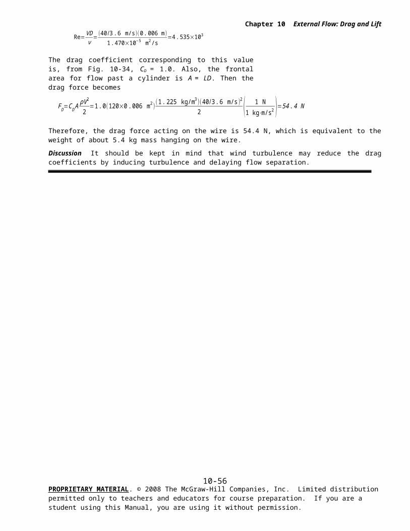
3 m/s
2.5 m
Chapter 10 External Flow: Drag and Lift
Review Problems
10-91
Solution A fluid flows over a 2.5-m long flat plate. The thickness of the boundary layer at intervals of 0.25 m is to be determined and plotted against the distance from the leading edge for air, water, and oil.
Assumptions 1 The flow is steady and incompressible. 2 The critical Reynolds number is Recr = 5105. 3 Air is an ideal gas. 4 The surface of the plate is smooth.
Properties The kinematic viscosity of the three fluids at 1 atm and 20°C are: = 1.516×10⁻⁵ m2/s for air , = m/ = (1.002×10⁻³ kg/m×s)/(998 kg/m3) = 1.004×10⁻⁶ m2/s for water, and = 9.429×10⁻⁴ m2/s for oil.
Analysis The thickness of the boundary layer along the flow for laminar and turbulent flows is given by
Laminar flow:
δ x=4 . 91 x
Rex1 /2
, Turbulent flow:
δ x=0 .38 x
Rex1 /5
(a) AIR: The Reynolds number and the boundary layer thickness at the end of the first 0.25 m interval are
,
δ x=5 x
Rex1 /2 =
4 . 91×(0 . 25 m )(0 . 495×105 )0. 5
=5. 52×10−3 m
We repeat calculations for all 0.25 m intervals. The EES Equations window is printed below, along with the tabulated and plotted results.
V=3 "m/s"nu1=1.516E-5 "m2/s, Air"Re1=x*V/nu1delta1=4.91*x*Re1^(-0.5) "m, laminar flow"nu2=1.004E-6 "m2/s, water"Re2=x*V/nu2delta2=0.38*x*Re2^(-0.2) "m, turbulent flow"nu3=9.429E-4 "m2/s, oil"Re3=x*V/nu3delta3=4.91*x*Re3^(-0.5) "m, laminar flow"
x, cm Air Water Oil
Re x Re x Re x
0.000.250.500.751.001.251.501.752.002.252.50
0.000E+004.947E+049.894E+041.484E+051.979E+052.474E+052.968E+053.463E+053.958E+054.453E+054.947E+05
0.00000.00550.00780.00960.01100.01230.01350.01460.01560.01660.0175
0.000E+007.470E+051.494E+062.241E+062.988E+063.735E+064.482E+065.229E+065.976E+066.723E+067.470E+06
0.00000.00640.01110.01530.01930.02300.02660.03010.03350.03690.0401
0.000E+007.954E+021.591E+032.386E+033.182E+033.977E+034.773E+035.568E+036.363E+037.159E+037.954E+03
0.00000.04350.06160.07540.08700.09730.10660.11520.12310.13060.1376
Discussion Note that the flow is laminar for (a) and (c), and turbulent for (b). Also note that the thickness of the boundary layer is very small for air and water, but it is very large for oil. This is due to the high viscosity of oil.
PROPRIETARY MATERIAL. © 2008 The McGraw-Hill Companies, Inc. Limited distribution permitted only to teachers and educators for course preparation. If you are a student using this Manual, you are using it without permission.
0 0.5 1 1.5 2 2.50
0.02
0.04
0.06
0.08
0.1
0.12
0.14
x, m
, m
Oil
Air
Water
10-56

Iced waterDo = 1 m
0C
V = 35 km/hT = 25C
Chapter 10 External Flow: Drag and Lift
10-92 Solution A large spherical tank located outdoors is subjected to winds. The drag force exerted on the tank by the winds is to be determined.
Assumptions 1 The outer surfaces of the tank are smooth. 2 Air flow in the wind is steady and incompressible, and flow around the tank is uniform. 3 Turbulence in the wind is not considered. 4 The effect of any support bars on flow and drag is negligible.
Properties The density and kinematic viscosity of air at 1 atm and 25C are = 1.184 kg/m3 and = 1.56210-5 m2/s.
Analysis Noting that D = 1 m and 1 m/s = 3.6 km/h, the Reynolds number for the flow is
The drag coefficient for a smooth sphere corresponding to this Reynolds number is, from Fig. 10-36, CD = 0.065. Also, the frontal area for flow past a sphere is A = D2/4. Then the drag force becomes
Discussion Note that the drag coefficient is very low in this case since the flow is turbulent (Re > 2105). Also, it should be kept in mind that wind turbulence may affect the drag coefficient.
PROPRIETARY MATERIAL. © 2008 The McGraw-Hill Companies, Inc. Limited distribution permitted only to teachers and educators for course preparation. If you are a student using this Manual, you are using it without permission.
10-57
4 m2 m
4 m
4 m
0.15 m
Concrete
AD
Chapter 10 External Flow: Drag and Lift
10-93 Solution A rectangular advertisement panel attached to a rectangular concrete block by two poles is to withstand high winds. For a given maximum wind speed, the maximum drag force on the panel and the poles, and the minimum length L of the concrete block for the panel to resist the winds are to be determined.
Assumptions 1 The flow of air is steady and incompressible. 2 The wind is normal to the panel (to check for the worst case). 3 The flow is turbulent so that the tabulated value of the drag coefficients can be used.
Properties In turbulent flow, the drag coefficient is CD = 0.3 for a circular rod, and CD = 2.0 for a thin rectangular plate (Table 10-2). The densities of air and concrete block are given to be = 1.30 kg/m3 and c = 2300 kg/m3.
Analysis (a) The drag force acting on the panel is
FD ,panel=CD AρV 2
2
=(2.0 )(2×4 m2 )(1 .30 kg/m3 )(150 /3 .6 m/s )2
2 (1 N1 kg⋅m/s2 )
=18,000 N
(b) The drag force acting on each pole is
FD ,pole=CD AρV 2
2
=(0.3 )(0 .05×4 m2 )(1 .30 kg/m3 )(150 /3 .6 m/s)2
2 (1 N1 kg⋅m/s2 )
=68 NTherefore, the drag force acting on both poles is 68 2 = 136 N. Note that the drag force acting on poles is negligible compared to the drag force acting on the panel.
(c) The weight of the concrete block is
W=mg=ρgV =(2300 kg/m3 )(9 .81 m/s2 )(L×4 m×0 .15 m )(1 N
1 kg⋅m/s2 )=13,540 L N
Note that the resultant drag force on the panel passes through its center, the drag force on the pole passes through the center of the pole, and the weight of the panel passes through the center of the block. When the concrete block is first tipped, the wind-loaded side of the block will be lifted off the ground, and thus the entire reaction force from the ground will act on the other side. Taking the moment about this side and setting it equal to zero gives
∑M=0 → F D ,panel×(1+4+0 . 15)+FD ,pole×(2+0 .15 )−W×(L/2)=0
Substituting and solving for L gives
18 , 000×5 .15+136×2. 15−13 ,540 L×L/2=0 → L=3 . 70 m
Therefore, the minimum length of the concrete block must be L = 3.70.
Discussion This length appears to be large and impractical. It can be reduced to a more reasonable value by (a) increasing the height of the concrete block, (b) reducing the length of the poles (and thus the tipping moment), or (c) by attaching the concrete block to the ground (through long nails, for example).
PROPRIETARY MATERIAL. © 2008 The McGraw-Hill Companies, Inc. Limited distribution permitted only to teachers and educators for course preparation. If you are a student using this Manual, you are using it without permission.
10-58
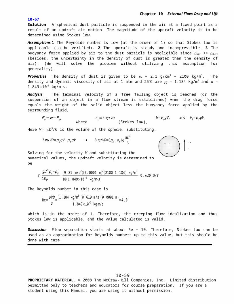
30 km/h
Boat
Chapter 10 External Flow: Drag and Lift
10-94 Solution The bottom surface of a plastic boat is approximated as a flat surface. The friction drag exerted on the bottom surface of the boat by water and the power needed to overcome it are to be determined.
Assumptions 1 The flow is steady and incompressible. 2 The water is calm (no significant currents or waves). 3 The water flow is turbulent over the entire surface because of the constant agitation of the boat. 4 The bottom surface of the boat is a flat surface, and it is smooth.
Properties The density and dynamic viscosity of water at 15C are = 999.1 kg/m3 and m = 1.138×10⁻³ kg/m×s.
Analysis The Reynolds number at the end of the bottom surface of the boat is
ReL=ρ VL
μ=(999. 1 kg/m3 )(30/3 .6 m/s )(2 m)
1. 138×10−3 kg/m⋅s=1 . 463×107
The flow is assumed to be turbulent over the entire surface. Then the average friction coefficient and the drag force acting on the surface becomes
C f=0 . 074
ReL1/5
= 0 .074
(1 . 463×107 )1 /5=0 .00273
FD=C f AρV 2
2=( 0. 00273 )[1 .5×2 m2 ]
( 999.1 kg/m3 )(30/3. 6 m/s )2
2 (1 N1 kg . m/s2 )=284 .1 N
Noting that power is force times velocity, the power needed to overcome this drag force is
W drag=FD V =(284 .1 N )(30/3 .6 m/s )(1 kW1000 N⋅m/s )=2 .37 kW
Discussion Note that the calculated drag force (and the power required to overcome it) is relatively small. This is not surprising since the drag force for blunt bodies (including those partially immersed in a liquid) is almost entirely due to pressure drag, and the friction drag is practically negligible compared to the pressure drag.
PROPRIETARY MATERIAL. © 2008 The McGraw-Hill Companies, Inc. Limited distribution permitted only to teachers and educators for course preparation. If you are a student using this Manual, you are using it without permission.
10-59
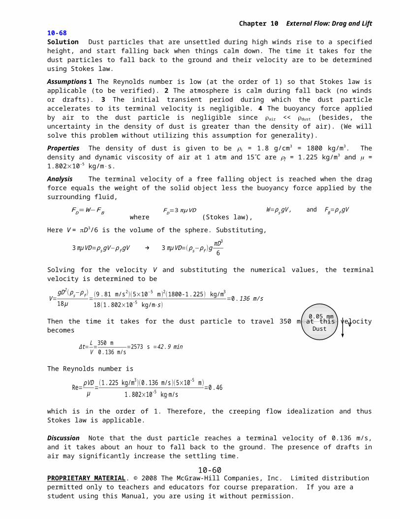
Chapter 10 External Flow: Drag and Lift
10-95
Solution The previous problem is reconsidered. The effect of boat speed on the drag force acting on the bottom surface of the boat and the power needed to overcome as the boat speed varies from 0 to 100 km/h in increments of 10 km/h is to be investigated.
Analysis The EES Equations window is printed below, along with the tabulated and plotted results.
rho=999.1 "kg/m3"mu=1.138E-3 "m2/s"V=Vel/3.6 "m/s"L=2 "m"W=1.5 "m"A=L*W
Re=rho*L*V/muCf=0.074/Re^0.2g=9.81 "m/s2"F=Cf*A*(rho*V^2)/2 "N"P_drag=F*V/1000 "kW"
V, km/h Re Cf Fdrag, N Pdrag, kW
0102030405060708090100
04.877E+069.755E+061.463E+071.951E+072.439E+072.926E+073.414E+073.902E+074.390E+074.877E+07
00.003400.002960.002730.002580.002460.002380.002300.002240.002190.00215
0391372844777139891306166120532481
0.00.10.82.45.39.916.525.436.951.368.9
Discussion The curves look similar at first glance, but in fact Fdrag increases like V 2, while Fdrag increases like V 3.
PROPRIETARY MATERIAL. © 2008 The McGraw-Hill Companies, Inc. Limited distribution permitted only to teachers and educators for course preparation. If you are a student using this Manual, you are using it without permission.
0 20 40 60 80 1000
500
1000
1500
2000
2500
V, km/h
Fd
rag, N
0 20 40 60 80 1000
10
20
30
40
50
60
70
V, km/h
Pd
rag, k
W
10-60
950 N
8 m
Chapter 10 External Flow: Drag and Lift
10-96 Solution The total weight of a paratrooper and its parachute is given. The terminal velocity of the paratrooper in air is to be determined.
Assumptions 1 The air flow over the parachute is turbulent so that the tabulated value of the drag coefficient can be used. 2 The variation of the air properties with altitude is negligible. 3 The buoyancy force applied by air to the person (and the parachute) is negligible because of the small volume occupied and the low air density.
Properties The density of air is given to be 1.20 kg/m3. The drag coefficient of a parachute is CD = 1.3.
Analysis The terminal velocity of a free falling object is reached when the drag force equals the weight of the solid object, less the buoyancy force applied by the fluid, which is negligible in this case,
FD=W−FB where FD=CD A
ρ f V 2
2, W=mg=950 N , and FB≃0
where A = D2/4 is the frontal area. Substituting and simplifying,
CD Aρf V 2
2=W → CD
πD2
4
ρf V 2
2=W
Solving for V and substituting,
V=√ 8WCD πD2 ρf
=√ 8(950 N)1 .3π (8 m)2 (1.20 kg/m3 ) (1 kg⋅m/s2
1 N )=4 .9 m/s
Therefore, the velocity of the paratrooper will remain constant when it reaches the terminal velocity of 4.9 m/s = 18 km/h.
Discussion The simple analysis above gives us a rough value for the terminal velocity. A more accurate answer can be obtained by a more detailed (and complex) analysis by considering the variation of air density with altitude, and by considering the uncertainty in the drag coefficient.
PROPRIETARY MATERIAL. © 2008 The McGraw-Hill Companies, Inc. Limited distribution permitted only to teachers and educators for course preparation. If you are a student using this Manual, you are using it without permission.
10-61
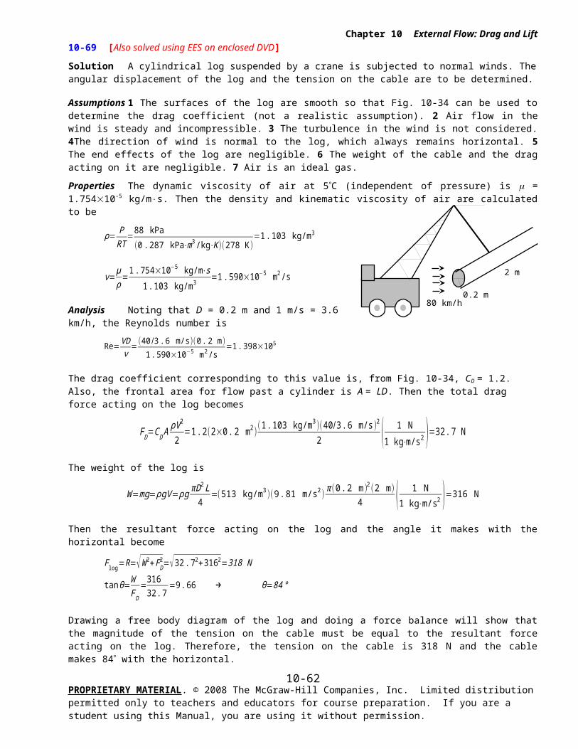
Chapter 10 External Flow: Drag and Lift
10-97 Solution A fairing is installed to the front of a rig to reduce the drag coefficient. The maximum speed of the rig after the fairing is installed is to be determined.
Assumptions 1 The rig moves steadily at a constant velocity on a straight path in calm weather. 2 The bearing friction resistance is constant. 3 The effect of velocity on the drag and rolling resistance coefficients is negligible. 4 The buoyancy of air is negligible. 5 The power produced by the engine is used to overcome rolling resistance, bearing friction, and aerodynamic drag.
Properties The density of air is given to be 1.25 kg/m3. The drag coefficient of the rig is given to be CD = 0.96, and decreases to CD = 0.76 when a fairing is installed. The rolling resistance coefficient is CRR = 0.05.
Analysis The bearing friction resistance is given to be Fbearing = 350 N. The rolling resistance is
FRR=CRR W=0 . 05(17 , 000 kg )( 9. 81 m/s2 )(1 N
1 kg⋅m/s2 )=8339 N
The maximum drag occurs at maximum velocity, and its value before the fairing is installed is
FD1=CD A
ρV 12
2=(0 . 96 )(9 .2 m2 )
(1 .25 kg/m3)(110 /3 .6 m/s )2
2 ( 1 N
1 kg⋅m/s2 )=5154 N
Power is force times velocity, and thus the power needed to overcome bearing friction, drag, and rolling resistance is the product of the sum of these forces and the velocity of the rig,
W total=W bearing+W drag+W RR=(F bearing+FD+FRR )V
¿(350+8339+5154 )(110 /3 . 6 m/s)(1 kW1000 N⋅m/s )
¿423 kW
The maximum velocity the rig can attain at the same power of 423 kW after the fairing is installed is determined by setting the sum of the bearing friction, rolling resistance, and the drag force equal to 423 kW,
W total=W bearing+W drag2+W RR=(F bearing+FD2+FRR )V 2=(350+CD 2 AρV 2
2
2+5154)V 2
Substituting the known quantities,
(423 kW )( 1000 N⋅m/s1 kW )=(350 N+(0 . 76)(9 . 2 m2 )
(1. 25 kg/m3 )V 22
2 ( 1 N1 kg⋅m/s2 )+5154 N)V 2
or,
423,000 =5504 V 2+4 .37 V 23
Solving it with an equation solver gives V2 = 36.9 m/s = 133 km/h.
Discussion Note that the maximum velocity of the rig increases from 110 km/h to 133 km/h as a result of reducing its drag coefficient from 0.96 to 0.76 while holding the bearing friction and the rolling resistance constant.
PROPRIETARY MATERIAL. © 2008 The McGraw-Hill Companies, Inc. Limited distribution permitted only to teachers and educators for course preparation. If you are a student using this Manual, you are using it without permission.
10-62
0.12 m/s
3 mm
Glassball
Chapter 10 External Flow: Drag and Lift
10-98 Solution A spherical object is dropped into a fluid, and its terminal velocity is measured. The viscosity of the fluid is to be determined.
Assumptions 1 The Reynolds number is low (at the order of 1) so that Stokes law is applicable (to be verified). 2 The diameter of the tube that contains the fluid is large enough to simulate free fall in an unbounded fluid body. 3 The tube is long enough to assure that the velocity measured is the terminal velocity.
Properties The density of glass ball is given to be s = 2500 kg/m3. The density of the fluid is given to be f = 875 kg/m3.
Analysis The terminal velocity of a free falling object is reached when the drag force equals the weight of the solid object, less the buoyancy force applied by the fluid,
FD=W−FB where
FD=3 πμVD (Stokes law),
W=ρs gV , and FB= ρf gV
Here V = D3/6 is the volume of the sphere. Substituting and simplifying,
3 πμVD=ρs gV −ρf gV → 3 πμ VD=( ρ s−ρf )gπD3
6
Solving for m and substituting, the dynamic viscosity of the fluid is determined to be
μ=gD2 ( ρs−ρ f )18 V
=(9 .81 m/s2 )(0 .003 m )2(2500-875 ) kg/m3
18(0 .12 m/s )=0 .0664 kg/m⋅s
The Reynolds number is
Re= ρVDμ
=(875 kg/m3 )(0.12 m/s )(0 .003 m )
0 .0664 kg⋅m/s=4 . 74
which is at the order of 1. Therefore, the creeping flow idealization is valid.
Discussion Flow separation starts at about Re = 10. Therefore, Stokes law can be used for Reynolds numbers up to this value, but this should be done with care.
PROPRIETARY MATERIAL. © 2008 The McGraw-Hill Companies, Inc. Limited distribution permitted only to teachers and educators for course preparation. If you are a student using this Manual, you are using it without permission.
10-63
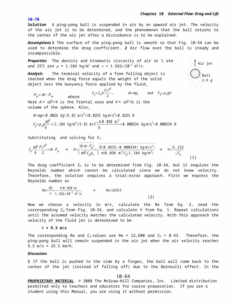
W=mg
3 mm
Aluminumball
Glycerin
FD FB
Chapter 10 External Flow: Drag and Lift
10-99 Solution Spherical aluminum balls are dropped into glycerin, and their terminal velocities are measured. The velocities are to be compared to those predicted by Stokes law, and the error involved is to be determined.
Assumptions 1 The Reynolds number is low (at the order of 1) so that Stokes law is applicable (to be verified). 2 The diameter of the tube that contains the fluid is large enough to simulate free fall in an unbounded fluid body. 3 The tube is long enough to assure that the velocity measured is terminal velocity.
Properties The density of aluminum balls is given to be s = 2700 kg/m3. The density and viscosity of glycerin are given to be f = 1274 kg/m3 and m = 1 kg/m×s.
Analysis The terminal velocity of a free falling object is reached when the drag force equals the weight of the solid object, less the buoyancy force applied by the fluid,
FD=W−FB where
FD=3 πμVD (Stokes law),
W=ρs gV , and FB= ρf gV
Here V = D3/6 is the volume of the sphere. Substituting and simplifying,
3 πμVD=ρs gV −ρf gV → 3 πμ VD=( ρ s−ρf )gπD3
6
Solving for the terminal velocity V of the ball gives
V=
gD2( ρ s− ρf )18 μ
(a) D = 2 mm and V = 3.2 mm/s
V=(9.81 m/s2 )(0 .002 m)2 (2700-1274 ) kg/m3
18 (1 kg/ m⋅s )=0 .00311 m/s=3. 11 mm/s
Error=V experimental−V Stokes
V experimental
=3.2−3 .113.2
=0 .029 or 2 .9%
(b) D = 4 mm and V = 12.8 mm/s
V=(9.81 m/s2 )(0 .004 m )2(2700-1274 ) kg/m3
18 (1 kg/ m⋅s )=0 .0124 m/s=12 . 4 mm/s
Error=V experimental−V Stokes
V experimental
=12 .8−12. 412 .8
=0 .029 or 2 . 9%
(c) D = 10 mm and V = 60.4 mm/s
V=(9.81 m/s2 )(0 .010 m)2 (2700-1274 ) kg/m3
18 (1 kg/ m⋅s )=0.0777 m/s=77 . 7 mm/s
Error=V experimental−V Stokes
V experimental
=60 .4−77 .760 .4
=−0. 287 or -28 .7%
There is a good agreement for the first two diameters. However the error for third one is large. The Reynolds number for each case is
(a) Re= ρVD
μ=(1274 kg/m3 )(0 . 0032 m/s )(0 .002 m )1 kg⋅m/s
=0 .008, (b) Re = 0.065, and (c) Re = 0.770.
We observe that Re << 1 for the first two cases, and thus the creeping flow idealization is applicable. But this is not the case for the third case.
Discussion If we used the general form of the equation (see next problem) we would obtain V = 59.7 mm/s for part (c), which is very close to the experimental result (60.4 mm/s).
PROPRIETARY MATERIAL. © 2008 The McGraw-Hill Companies, Inc. Limited distribution permitted only to teachers and educators for course preparation. If you are a student using this Manual, you are using it without permission.
10-64
W=mg
3 mm
Aluminumball
Glycerin
FD FB
Chapter 10 External Flow: Drag and Lift
10-100 Solution Spherical aluminum balls are dropped into glycerin, and their terminal velocities are measured. The velocities predicted by general form of Stokes law and the error involved are to be determined.
Assumptions 1 The Reynolds number is low (of order 1) so that Stokes law is applicable (to be verified). 2 The diameter of the tube that contains the fluid is large enough to simulate free fall in an unbounded fluid body. 3 The tube is long enough to assure that the velocity measured is terminal velocity.
Properties The density of aluminum balls is given to be s = 2700 kg/m3. The density and viscosity of glycerin are given to be f = 1274 kg/m3 and m = 1 kg/m×s.
Analysis The terminal velocity of a free falling object is reached when the drag force equals the weight of the solid object, less the buoyancy force applied by the fluid,
FD=W−FB
where FD=3πμ DV +(9 π /16 ) ρs V 2 D2
, W=ρs gV , and FB= ρf gV
Here V = D3/6 is the volume of the sphere. Substituting and simplifying,
3 πμVD+(9π /16) ρ s V 2 D2=( ρ s−ρ f )gπD3
6
Solving for the terminal velocity V of the ball gives
V=−b+√b2−4 ac
2 a where
a=9 π16
ρs D2
, b=3 πμ D
, and
c=−( ρ s−ρ f )gπD3
6
(a) D = 2 mm and V = 3.2 mm/s: a = 0.01909, b = 0.01885, c = -0.0000586
V=−0 . 01885+√(0 .01885 )2−4×0 .01909×(−0 . 0000586 )
2×0 .01909=0.00310 m/s=3 .10 mm/s
Error=V experimental−V Stokes
V experimental
=3.2−3 .103 .2
=0 .032 or 3 .2%
(b) D = 4 mm and V = 12.8 mm/s: a = 0.07634, b = 0.0377, c = -0.0004688
V=−0 . 0377+√( 0. 0377 )2−4×0 .07634×(−0 . 0004688)
2×0 .07634=0 . 0121 m/s=12 . 1 mm/s
Error=V experimental−V Stokes
V experimental
=12 .8−12. 112 .8
=0 .052 or 5 . 2%
(c) D = 10 mm and V = 60.4 mm/s: a = 0.4771, b = 0.09425, c = -0.007325
V=−0 . 09425+√(0 .09425 )2−4×0 .3771×(−0 . 007325)
2×0 . 4771=0 . 0597 m/s=59 . 7 mm/s
Error=V experimental−V Stokes
V experimental
=60 .4−59 .760 .4
=0 .012 or 1 .2%
The Reynolds number for the three cases are
(a) Re= ρVD
μ=(1274 kg/m3 )(0 .0032 m/s )(0 .002 m )1 kg⋅m/s
=0 .008, (b) Re = 0.065, and (c) Re = 0.770.
Discussion There is a good agreement for the third case (case c), but the general Stokes law increased the error for the first two cases (cases a and b) from 2.9% and 2.9% to 3.2% and 5.2%, respectively. Therefore, the basic form of Stokes law should be preferred when the Reynolds number is much lower than 1.
PROPRIETARY MATERIAL. © 2008 The McGraw-Hill Companies, Inc. Limited distribution permitted only to teachers and educators for course preparation. If you are a student using this Manual, you are using it without permission.
10-65
Chapter 10 External Flow: Drag and Lift
PROPRIETARY MATERIAL. © 2008 The McGraw-Hill Companies, Inc. Limited distribution permitted only to teachers and educators for course preparation. If you are a student using this Manual, you are using it without permission.
10-66
Chapter 10 External Flow: Drag and Lift
Design and Essay Problems
10-101 to 10-103 Solution Students’ essays and designs should be unique and will differ from each other.
PROPRIETARY MATERIAL. © 2008 The McGraw-Hill Companies, Inc. Limited distribution permitted only to teachers and educators for course preparation. If you are a student using this Manual, you are using it without permission.
10-67