46.- Design and Construction of a Nineteen-Storey Load ... · The high part of the site ... 284...
5
46.- Design and Construction of a Nineteen-Storey Load-bearing Brick Building by B. A. HASELTlNE and Y. T. Av Jenkins & Potter, COl1sulting Engineers, London, WCl A BSTRACT The circumstances leading up 10 lhe decision 10 use bricklVork for a large hOllsing scheme aI PortsdolVl1 , Hampshire are described. The scheme ifle/udes filteen- , seventeen- and nine- teen-storey !ower blocks, of which tltirteen, fifteen and seven/een storeys respective/y are constructed in load- bearing brickwork. There is Gn associa/ed low-rise del 'elopmelll of fOllr-, six- and eight-Slorey /oad- bearillg brick bllildillgs. The engin- eering desigll of lhe nineteen-storey block is described alui lhe brickwork strengths are gi ven , (oge/l1er \Vi/h 011 ou/fine Df lhe specificatioll lIsed. The early COl1st r uction difficulties and teclmiques are indicated. The paper ;s iIIuslraled \Vilh diagrams, plalls alui pholographs of lhe bllilding. Etude et Construction d 'un Bâtiment en Briques Porleuses de 19 Elages Entwurf und A usführung eines neunzelrnstockigen Gebaudes aus last- tl'agenden Ziegelmallel·n L'arlic!e décrit les circonstances qui 0111 conduil à décider d 'uliliser la maçollllerie en briques pour le pro- jel d'un grand ensemble à PorlsdolVn , Hampshire. Ce projet comprend des- 10ll rs de 15,17 et 19 élages dont 13 , 15 el 17 é/ages sonl construites compJetement en maçonnerie en briques porteuse. Y sonl associées des contructions en briques porleuse d'une dimellsioll 1110;I1S élel'ée, de 4, 6 el 8 étages. L'élude technique de la lour de 19 élages esl décrile et les résislances de la maçonnerie en briqlles S0111 dOI1 - nées ains; qu' 1111 aperçu du cohier des charges. Les premieres difficull és tech niques de cOllstruction sonl indi- quées. L'arlic!e est i11l1stré par des diagrammes, tles plans, el des pll%- graphies des bálimenls. Die Zll der Entscheidung, Ziegel- mauerwerkfiir eillen grossen Wohnbe- zirk in Portsdown , Hampshire za I'erwenden , führellden Umstõnde sind beschriebel1. Im Wollllbez;rk srehell Wohnhochhiiuser mil 15, 17 IInd 19 Slockwerken, 1'011 denen 13, 15 bzw. 17 Stockwerke aus (ragendem Ziegel- mauenverk erstel!l wurdell. Dami/ verbullden ;sl d;e Enlwickhmg von 4- , 6- und 8-slõckigen Gebiiuden mit tragendem Zi egelmauerwerk. Der Ballplan des 19 Slockwerke hohel1 Blocks i st beschrieben. Zusammen mil einem Oberblick der Giitel'Orschriften Shld die Mallerwerksfesligkeitel1 al1- gegebell. Auf die frühe ren KOl1slrukl- iOlls-Sclllvierigkeiten und -Tecllllikel1 wird hingewiesell. Der AlIfsatz ist mil graphischen Darstellungen , Planen und Plzolographien des Gebiiudes l'ersehel1. J. INTRODUCTI ON In 1965, lhe Ci ty of Portsmouth held an architectural competition for the design of a complex housiog scheme on a mosl impressive 20-acre site aI the foot of Portsdown Hill. The hi gh part of the site commands magnificent views over Portsmouth and the Solent to the Isle of Wight, a nd , conversely, lhe sile is visible over a large distance. The clients, therefore, were anxious that the development would enhance, rather Ihan spo il lhe scenery. The competition drew entries from ninety-one compelitors, but lhe assessors were satisfied Ihat the outstand ing scheme was ooe visualized from the outset in brickwork, submitted by Theakston & Duel!. The successful architects incorporated 523 dwellings in their plan (Figure I), in addition to li censed premises, shops, tenants' meeting hall, play area and 67 1 parldng spaces (260 under cover). In order to discourage future development spilling up the hill behind the sile, the architects created a wa ll along l he top of the site, with a line of six- and eight-slorey maisoneltes, pierced by si milar poinl blocks fifteen, seventeen and nineteen storeys high. As the slope of the si te fa ll s away there are two more parallel rows of dwellings, firstly four- storey rnai sonettes, and then two-storey houses. A number of one-storey o ld persons' homes complete the layout. 282 2. CHOICE OF STRUCTURE The architects alwa ys envisaged a brick-faced scheme, as this, th ey believed, was the on ly way of meeting the competitian brief, which was to reduce ma int enaDce costs to the Counc il to a rninirnum, consistent with architectural quality a nd suitability to lhe importance of the site. At the same time, it appeared that the use of brick for the vertical slructure as well would prove economical. Studies were carried out by Jenkins & Potter on the following structural systems, afler it had already been decided th at no fully ind ustria li zed system could be used without alter in g the sc heme so much that the original concept wo uld be lost. (I) 111 siru concrete wall structure. (2) Battery-cast precast wall structure. (3) Load-bearing brickwork, wilh il1 silll concrele floors. The quanlity surveyor s, Davis Be lfield & Everest, costed the various schemes and came to the conclusion that No . 3 (Ioad-bearing brickwork) was definitely lhe cheapest. At the time that a decision had to be made, it was Ministry of Housing & Local Government policy to encourage the maximum use af in dustrializeti-building techniques, and so me opposition wa s met before brick-
Transcript of 46.- Design and Construction of a Nineteen-Storey Load ... · The high part of the site ... 284...
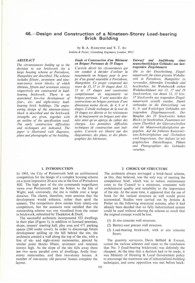
46.- Design and Construction of a Nineteen-Storey Load-bearing Brick Building
by B. A. HASELTlNE and Y. T. Av Jenkins & Potter, COl1sulting Engineers, London, WCl
A BSTRACT The circumstances leading up 10 lhe decision 10 use bricklVork for a large hOllsing scheme aI PortsdolVl1, Hampshire are described. The scheme ifle/udes filteen- , seventeen- and nineteen-storey !ower blocks, of which tltirteen, fifteen and seven/een storeys respective/y are constructed in loadbearing brickwork. There is Gn
associa/ed low-rise del'elopmelll of fOllr-, six- and eight-Slorey /oadbearillg brick bllildillgs. The engineering desigll of lhe nineteen-storey block is described alui lhe brickwork strengths are given , (oge/l1er \Vi/h 011 ou/fine Df lhe specificatioll lIsed. The early COl1struction difficulties and teclmiques are indicated. The paper ;s iIIuslraled \Vilh diagrams, plalls alui pholographs of lhe bllilding.
Etude et Construction d'un Bâtiment en Briques Porleuses de 19 Elages
Entwurf und A usführung eines neunzelrnstockigen Gebaudes aus lasttl'agenden Ziegelmallel·n L'arlic!e décrit les circonstances qui
0111 conduil à décider d 'uliliser la maçollllerie en briques pour le projel d'un grand ensemble à PorlsdolVn, Hampshire. Ce projet comprend des-10llrs de 15,17 et 19 élages dont 13, 15 el 17 é/ages sonl construites compJetement en maçonnerie en briques porteuse. Y sonl associées des contructions en briques porleuse d'une dimellsioll 1110;I1S élel'ée, de 4, 6 el 8 étages. L'élude technique de la lour de 19 élages esl décrile et les résislances de la maçonnerie en briqlles S0111 dOI1-nées ains; qu' 1111 aperçu du cohier des charges. Les premieres difficullés techniques de cOllstruction sonl indiquées. L'arlic!e est i11l1stré par des diagrammes, tles plans, el des pll%graphies des bálimenls.
Die Zll der Entscheidung, Ziegelmauerwerkfiir eillen grossen Wohnbezirk in Por tsdown , Hampshire za I'erwenden , führellden Umstõnde sind beschriebel1. Im Wollllbez;rk srehell Wohnhochhiiuser mil 15, 17 IInd 19 Slockwerken, 1'011 denen 13, 15 bzw. 17 Stockwerke aus (ragendem Ziegelmauenverk erstel!l wurdell. Dami/ verbullden ;sl d;e Enlwickhmg von 4-, 6- und 8-slõckigen Gebiiuden mit tragendem Ziegelmauerwerk. Der Ballplan des 19 Slockwerke hohel1 Blocks ist beschrieben. Zusammen mil einem Oberblick der Giitel'Orschriften Shld die Mallerwerksfesligkeitel1 al1-gegebell. Auf die früheren KOl1slrukliOlls-Sclllvierigkeiten und -Tecllllikel1 wird hingewiesell. Der AlIfsatz ist mil graphischen Darstellungen, Planen und Plzolographien des Gebiiudes l'ersehel1.
J. INTRODUCTION In 1965, lhe City of Portsmouth held an architectural competition for the design of a complex housiog scheme on a mosl impressive 20-acre site aI the foot of Portsdown Hill. The high part of the site commands magnificent views over Portsmouth and the Solent to the Isle of Wight, and , conversely, lhe sile is visible over a large distance. The clients, therefore, were anxious that the development would enhance, rather Ihan spoil lhe scenery. The competition drew entries from ninety-one compelitors, but lhe assessors were satisfied Ihat the outstand ing scheme was ooe visualized from the outset in brickwork, submitted by Theakston & Duel!.
The successful architects incorporated 523 dwellings in their plan (Figure I), in addition to licensed premises, shops, tenants' meeting hall, play area and 67 1 parldng spaces (260 under cover). In order to discourage future development spilling up the hill behind the sile, the architects created a wall along lhe top of the site, with a line of six- and eight-slorey maisoneltes, pierced by si milar poinl blocks fifteen, seventeen and nineteen storeys high. As the slope of the si te fa lls away there are two more parallel rows of dwellings, firstly fourstorey rnaisonettes, and then two-storey houses. A number of one-storey old persons' homes complete the layout.
282
2. CHOICE OF STRUCTURE The architects always envisaged a brick-faced scheme, as this, they believed, was the on ly way of meeting the competit ian brief, which was to reduce ma intenaDce costs to the Council to a rninirnum, consistent with architectural quality and suitability to lhe importance of the site. At the same time, it appeared that the use of brick for the vertical slructure as well would prove economical. Studies were carried out by Jenkins & Potter on the following structural systems, afler it had already been decided that no fully ind ustria lized system could be used without altering the scheme so much that the original concept would be lost.
( I) 111 siru concrete wall structure.
(2) Battery-cast precast wall structure.
(3) Load-bearing brickwork, wilh il1 silll concrele floors.
The quanlity surveyors, Davis Belfield & Everest, costed the various schemes and came to the conclusion that No. 3 (Ioad-bearing brickwork) was definitely lhe cheapest. At the time that a decision had to be made, it was Ministry of Housing & Local Government policy to encourage the maximum use af industrializeti-building techniques, and so me opposition was met before brick-

B. A. Haseltine and Y. T. Au 283
A Fifteen·storey block 8 Seventeen -storey block C Nineteen-storey block O Eight-storey wall blocks E Six-storey wall blocks F Four-storey maisonette blocks G Four-storey maisonette blocks H Two-storey split-Ievel terrace houses I One-storey old peoples' dwellings Total dwelling units: 523 Total covered parking: 260 Total ope" parking : 411 Total parking: 671 (1 ·26 spaces per dweHing)
FIGURE l - Site layout.
work was finally chosen. Naturally, as much rationalization as possible was aimed at in the design of the brickwork and the internaI work. It was interesting to notethat slightlyfewer site men wereforecast to be required by the quantity surveyor in their exercise for the loadbearing brickwork scheme than would have been needed for the precas! battery system!
Ucensed premises with three-bedroom maisonette
Supermarket with three-bedroom maisonette Shops with three-bedroom maisonette Tenants' meeting hal!
e Five activity areas, covering seventy parking spaces
Shopping square, covering th irty parking spaces and stm8ge space
9 Community sQuare h Redirected pu
.R " 3. DESIGN FEATURES OF THE NINETEEN-STOREY '1
BLOCK ~~~~9F~~ Although there are many interesting points which could be made about the design of the whole scheme, this paper is concerned primarily with the nineteen-storey block, of which seventeen storeys are in load-bearing brickwork. Jt is believed to be the tallest load·bearing brick structure in the U K. The structure of the fifteenand seventeen-storey blocks is similar to that of the nineteen-starey ane, and a plan is shown in Figure 2.
I! could be said that the layout of load-bearing walls is not ideal for a structure seventeen storeys high, because, although Ibere are enough walls to carry the verlical load, there are a lot of openings which reduce the effectiveness of the walls in resisting wind. Hawever, by making use of the composite action of brickwork, reinforced-concrele floors and special bcams, it proved possible lo give lhe archilecl lhe plan he wanled while achieving an economical structure.
LR
•
• •
LR
FIGURE 2- Typical f100r plan.

284 Design and Construction of a Nineteen-Storey Load-bearing Brick Building
3.1 Walls The site at Portsdown is extremely exposed and, apart from the wind problem, described in Section 3.3, the design team were concerned that driving rain might penetrate a normal cavily wall. After cost and design exercises it was decided to use 9-in. externaI walls , with the fio ar slabs expressed on the outside, and lO form a cavity by erecting a Iight inner skin of blockwork carried as a partition load on lhe floor slab, as shown in Figure 3, Seclion B-B. In this way less water should reach the cavily as lhe rain has lo penelrate a solid 9-in. wall before reaching it. Normal cavily-wall dampproaf courses were provided at each ficor leveI. This arrangement of walls was structurally as good as a cavity wall 4t in.- 2 in .-9 in. and was cheaper, whilst giving a better weather and thermal resistance.
.~ .~
B I I!!!!!!!l!! .~ ·{[trPs13
i I li! l!m!!! ... .J .J ,'pie... ~' lIlOCK
~ ~~
ELEv,.,TION AT WlNtlOW OPENING
/~ ."/~/
.'
" .m I [mo ,.,
FIGURE 3- $hcar linking beam details.
The internaI walls are 7-in . wide where possible, bUI in certain cases, mainly for architectural reasons, 9-in. load-bearing walls are also provided. Table I gives lhe variation of brick slrenglh wilh height for a lypical wall.
TABLE I - BRICK STRENGTH (WALL X, FIGURE 2)
F/oor Type 01 brick Streugth (lbflin' l
1st to 5th 9-in. Southwater Class 10 10000
5th to 7th 9·in. Holbrook perforated seconds 7 SOO
7th to 9th 7-in. Calculon 10000 9th to 12th 7-in. Calculon 7 SOO 12th to Toof 7~in. Calculon S 000
3.2 Floors
In a lall brick building, the fioors play an imporiam part in dislribuling horizontal forces from wall to wall and in balancing up minor eccentricities of construction. In this building the slabs were 7·in. reinforced concrele. Underftoor heating is being used, and, beca use of a previous investigation,l great care was exercised in the slab design to minimize the deflection. Top steel was
provided across ali the spans. To reduce the possibility of excessive thermal horizontal movements of the floor slab, possibly causing damage lo lhe externaI walls, and to reduce the possibility of cracking belween heated and unheated areas, lhe screed only was used for storage, and a i-in. layer of polystyrene was placed between lhe screed and reinforced slab.
3.3. Wind At the time the Porlsdown scheme was being designed, British Standard Code of Practice CP3, (Chapter V)' was lhe recognized code for calculating wind pressure. However, a paper by SCR UTON and NEWBERRy3 had been published, and, after discussion wilh the Building Research Station , a peak pressure of 36-4lbf/ft' at the top of the building, dropping to 24lbf/in' at the bottom, was selected for the structural designo Had exposure D of CP3, Chapler V, been used , the pressure would have been 29 Ibf/ft'.
The normal practice for lhe design of brick buildings against wind forces is to distribute the total overturning momenl on the building between the individual walls ar wall complexes in proportion to their stiffness. With so many openings in the load-bearing walls, this would have led to high uplifts at the windward end of lhe walls, and unacceptable compressive stresses in the leeward end. It was, therefore, necessary to unite certain walls to enable several short ones lo behave as if they were one loog one. ln conjunction with returo ends, very strong complex shapes were achieved. The verlical shear at lhe position of lhe openings was assessed from con~ ventional formulae, and this was translated into a force, which was used lo design the unifying beams. The shear forces so formed tended to be large and called for special consideralion. Figure 3, Section A- A, shows the solution, which was to use a fabricated sleel seclion, capable of taking the shear and bending forces when cased in concrete. By usiog a stee! section , lhe architect's requirement for true-storey-height slot windows was achieved, and lhe design slresses in lhe brickwork were brought down to acceptable leveis.
3.4 Accidental Damage Ronan Painl exploded on the slructural engineering scene when Portsdown was already well under way, but before the brickwork of lhe three tower blocks had slarted. While the layout could be lermed complex in relation to lhe Institution of Structural Engineers' Guidance Notes,' which were published much later, it seemed prudent to examine lhe structure from lhe paiOl af view that a main load-bearing walI rnight be removed by accidenl, but that in situ floor sl.bs, particularly with extra top steel, could be expecled to cantilever compositely with brickwork, ar span across enlargetl openings wilhoul actually failing in the full sense of the word. There is obviously no requirement that a damaged building should still be fil for habitation, only that it does not collapse. Accordingly, it appears thal the loss of any one wall , excepl the two unbuttressed externaI walls, I and 2 on Figure 2, would nol resul! in collapse. The absence of any worthwhile retum on walls I and 2 meanl that lhey could be more susceptible to damage, and that no carne r pier would rema in to help carry load from above in lhe event of a serious explosion. To overcome this problem , steel hangers have been incorporated ,
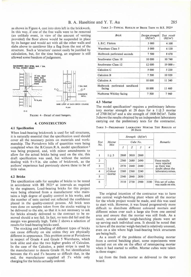
B. A. Haseltine and Y. T. Au 285 as shown in Figure 4, east into slots left in the briekwork. In this way, if one of the free walIs were to be removed (an unlikely event, in view af the amount af venting provided) the fioor above would be suspended in plaee by its hanger and would aet with alI the other walIs and slabs above to eantilever like a fiag from the rest of lhe strueture. Such a 'slrueture' eannol easily be justified by calculatian, but, for the time being, an engineer is still allowed some freedom of judgement.
OAl,VANlSfO IiIlD InEL !.lR. " OIA. TO n.u 8TORfY HEICHT
. ... . : ..
;: I " " DIA. MILO STEEL AOO. DRlllEO ANO TAPPED IIOTH (NOS
: !-----,---
c·c
UUu
r DIA. BAR
CONCRETE INFILL
WIAE lOOP AT EACH BAleK COUASE
PlAN
FIGURE 4---Delail of steel hangers.
4. CONSTRUCTION
4.1 Specification
When load-bearing briekwork is used for talI struelures, it is naturalIy essential that the speeifieation used should CQver ali the necessary points on materiais and workmanship. The Portsdown bilIs of quantities were being eompleted when the B.Ceram.R.A. model speeifieation s was being prepared, and, with minar amendments to alIow for the actual brieks being used on the site, this draft specification was used, but without the section dealing with 9 x 9 in. si te eubes of briekwork, as the authors' experienee had previously shown these to be of little value.
4.2 Bricks
The specification ealIs for samples of brieks to be tested in aeeordanee with BS 3921 6 aI intervals as required by the engineers. Load-bearing brieks for thi s projeet \Vere being obtained from a manufacturer who maintains a high degree of quality contraI in his works, and the number of tests earried out refieeted the confidence placed in the quality-control processo AlI brick tests were done on samples taken from the stocks waiting to be delivered to the si te, so that it is not necessary to ask for brieks already delivered to the contract to be removed should a test fai!. In fact, no tests did fail and the margin was generalIy high. Table 2 shows a seleetion of results for load-bearing brieks used.
The stoeking and label!ing of different types of bricks can cause difficulty on site unless they are physiealIy different in appearance. This problem arose at Portsdown in respect of Grade 4 and Grade 5 Warnhams, which look alike and also the two higher grades of Calculon. In the case of the Calculon, a paint stripe is used by lhe manufaeturer to denote Grade 10, but identifieation between the 4's and 5's became so difficult that , in the end, the manufaeturer supplied alI 5's while only charging for the bricks aetualIy ordered.
TABLE 2-TYPICAL REsULTIl OF BRTCK TESTS TO B.S. 3921 6
Bríck Design strength Test result (lbf1io' ) (lbf1io' )
L.B.C. Fletton 3000 4100
Warnham Class 5 5000 6130
Holbrook perforated seconds 7500 I 8670
Southwater Class 10 10000 10 740
Southwater Class 12 12000 19000+
Calculon C 5000 S 220
Calculon B 7500 10920
Calculon A 10 000 11340
Holbrook perforated sandfaced facing
I 10000 11 460
Nutborne Whitley facing 7500 7960
4.3 Mortar
The model specificationS requires a preliminary laboratory mortar strength at 28 days for a 1 :t:3 mortar of 2700 lbf/in' and a site strength of 1800 lbf/ in'. Table 3 shows the results obtained by an independent laboratory earrying out the preliminary tests for the contractor.
TABLE 3-PRELlMINARY LABORATORY MORTAR TEST RESULTS AT 28DAYS
Strength (lbfl in1)
Tesr Mortar Cube No. Remarks No. Mi:<
J 2 3 4
I 1:* : 3 2860 3010 2860
2 2360 2680 2490 These results -- were rejected
3 2570 2440 2440 as there was -- 1:*: 3 doubt about the
4 Colour 2360 2360 2240 laboratory mixes. - mortar
5 2540 2840 2850 -- --27Jõ 6 3110 2900 3180 This set of cubes was made on site.
The original intention of the contractor was to have one central weigh-batching plant where alI the morta r for the whole projeet would be made, and this was used to start witb. However, it was found progressively more diffi1,;uIt lo distribute different coloured morlars and different mixes over such a large site from Dne central area and ensure that the mortar was stil! fresh. As a result , several smalIer weigh-batching plants were seI up serving each individual area. It should be noted tbat to have ali the mortar weigb-batched is relatively unusual , even on a site where high load-bearing brick structures are being buil!.
As a result of the problems of distributing mortar from a central batching plant, some experiments were carried out on site on the etfect of retempering mortar when it had started to stiffen. Morlar cubes were taken in three stages :
(a) from the fresh mortar as delivered to the spot board.
286 Design and Construction of a Nineteen-Storey Load-bearing Brick Building
(b) when reconstituted, after the mortar had become too stifffor use by the bricklayer; and
(c) when lhe mortar had been further reconstiluted afler stage (b) had also become too stiff lo use.
Table 4 gives the results of the crushing tests on the sets of 3 x 3 in. cubes, together with the specified works strength. It can be seen that although retempering reduces lhe slrength, lhe result of stage (c) was sti ll within the specification. This would not necessarily have been the case, but for the fact that the sand used was particularly suitable for making a good strength mortar. As the strength became seriously reduced with prolonged waiting, a time limit af I! h was set fram mixing to use of mortar.
TABLE 4-RESULTS OF CRUSH ING TESTS QN 3 x 3 in. CUSES
1 :*:3 Colour mortar. Temperature: 21 ° 10 22°C. Humidity : 65 to 68 %. Specified work strength : 1800 Ibf/in2•
Time after 28~day test reslIlts illitialmixillg (individllal cubes)
(iI) (lb//in')
Fresh mortar t 2451 2364 2439
1st addition of water I± 24 15 2376 2402
2nd addition of water 2 2203 2251
3rd addition af water 2t 2053 2053
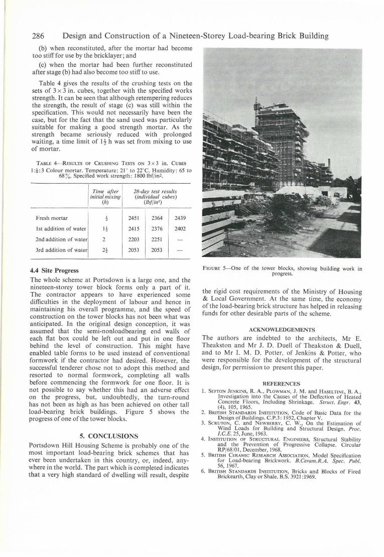
4.4 Site Progress The whole scheme at Portsdown is a large one, and the nineteen-storey IOwer block forms only a part of it. The contractor appears to have experienced some difficulties in lhe deployment of labour and hence in maintaining his overall programme, and the speed of construction 00 the tower blocks has not been what was anticipated. ln the original design conception, it was assurned that the semi-nonloadbearing end waUs of each flat box could be left out and pul in one tloor behind the leveI of conslruction. This might have enabled lable forms to be used inslead of conventional formwork if lhe contraclOr had desired. However, the successful tenderer chose not to adopt this rnethod and resorled to normal formwork, compleling ali waUs before commencing the formwork for one tloor. It is not possible lO say whelher this had an adverse effect on the progress, but, undoubtedly, the turn-round has not been as high as has been achieved on olher tall load-bearing brick buildings. Figure 5 shows the progress of one of the tower blocks.
5. CONCLUSIONS Portsdown Hill Housing Scheme is probably one of lhe most important load-bearing brick schemes that has ever been undertaken in this country, or, indeed, anywhere in the world. The part which is completed indicates that a very high standard of dweUing wiU result, despite
FIGURE 5- 0ne af the tower blocks, showing building work in progresso
the rigid cost requirements of the Ministry of Housing & Local Government. Al lhe same time, the economy afthe load-bearing brick structure has helped in releasing funds for other desirable paris of the scheme.
ACKNOWLEDGEMENTS
The aUlhors are indebled to the architects, Mr E. Theakston and M r J. D. Duell of Theakston & Duell, and to Mr I. M. D. Potter, of Jenkins & Potter, who were responsible for the development of lhe slruclural design , for permission to present this paper.
REFERENCES 1. SEFTON J EN KfNS, R. A., PLOWMAN, J. M. and HASELTINE, B. A. ,
Investigation into lhe Causes af the Deflection af Hcaled Concrete Floors, Including Shrinkage. SlrllCI. Ellgr. 43, (4), 105, 1965.
2. BRiTlSH STANDARDS INSTITUTION, Code af Basic Data for lhe Design ofBuildings. C.P.3: 1952, Chaplcr V.
3. SCRUTON, C. and NEWBERRY, C. W., On the Estimation af Wind Loads for Building and Structural Design. Proc. I.C.E. 25, June , 1963.
4. I N5llTIfTION DF STRUCTURAL ENGINEERS, Structura( Stability and the Prevcntion of Progressive Collapse. Circular RP/68/01,December, 1968.
5. BRITISH CERAMIC R ESEARCH ASSOCIATION, Model Spccification for Load-bcaring Brickwork. B.Ceram.R.A. Spec. Publ. 56. 1967.
6. BRITISH STANDARDS INSTITUTION, 8ricks and Blocks of Fired Brickearth. Clay Of Shale. B.S. 392 1 :1969.