Interface evolution in three-dimensions with curvature-dependent
790
4.17 Human–Machine Interface Evolution
G. KEVIN TOTHEROW (2002, 2005)
Partial List of HMI (Software is sold based on tag counts or I/O count. System sizes range from 64Software Suppliers: tags to unlimited system tags, and most vendors have a variety of options within
those sizes.)Adroit (www.adroit.co.za)Citect (www.citect.com)GE Automation Cimplicity (www.geindustrial.com/cwc/gefanuc/software.html)GE Automation Intellution (www.geindustrial.com/cwc/gefanuc/software.html)Iconics (www.iconics.com/)Rockwell Software (www.software.rockwell.com/navigation/products/index.cfm)Siemens (www.ad.siemens.de/hmi/html_76/products/software/wincc/index.htm)USData (www.usdata.com/usdata.html)Wonderware (www.wonderware.com)
Alarm Management TiPs (www.tipsweb.com/)Software Supplier:
INTRODUCTION
The devices that operators use to control process equipmenthave changed dramatically since the beginning of the digitalage. In some cases the operator is surrounded with multiplehuman–machine interfaces that more closely resembleNASA’s mission control center than the bench boards andinstrument panels of the past. In other cases the operatorcontrol room is becoming less significant as operators areusing handheld devices and Web pages to access the processinformation and control systems. However, we still see muchof the information presented on digital displays with imagesof the control stations, pushbuttons, and trend charts resem-bling bench-board equipment used 50 years ago. Further, thedigital displays are often installed and configured by techni-cians and system integrators without regard to supporting theoperator’s entire job, making the modern controls less intu-itive than the bench-board controls were (Figure 4.13h). Not-withstanding these issues, the digital display HMI hasallowed a single operator to monitor and control thousandsof process control loops from a single station (Figure 4.5c).The latest advances in HMI technology using inexpensivehardware, thin-clients, handheld computers, and cell phonetechnology have freed the operator from confinement to aparticular location for control and information systems.Understanding the evolution of the operator interface and thechanging role of the operator in a plant allows suppliers tobuild a better HMI product, plant engineers to pick the best
technology, and integrators to make the operator more effec-tive and efficient.
The modern HMI is at the evolutional convergence oftwo different development paths. One development path isthat of the operator console of the distributed control system(DCS). The other path is the development of the HMI for theprogrammable logic controller (PLC). This makes a chrono-logical discussion of HMI evolution somewhat difficult with-out getting the reader confused about which HMI is beingdiscussed. Therefore, this author will discuss the basic func-tions of an HMI and then attempt to describe the evolutionof DCS and PLC human–machine interfaces separately.Toward the end of this section, once again the discussion ofcontrol rooms, operators, and the future will apply to all HMIsystems.
FUNCTIONS OF THE CONTROL SYSTEM HMI
Operators have always had HMIs, with some of the oldestbeing the handle of a valve or the faceplate of a pneumaticcontroller. Although the term HMI can refer to any type ofdevice that allows a person to manipulate a machine or pro-cess, the term as used in process and manufacturing usuallyrefers to the display, computer, and software that serve thespecific role as the operator’s interface to a controller orcontrol system. The same display, computer, and softwareused for another purpose do not make an HMI. An analogy
© 2006 by Béla Lipták
4.17 Human–Machine Interface Evolution 791
is a taxi. A taxi is an automobile, boat, coach, or rickshawthat serves a specific function of transporting a customer fromone location to another. Use the same vehicle in anotherfunction and it is not a taxi.
This section uses the term HMI to describe the computerhardware and software that allow interaction between theoperator and the controls.
Many HMI product suites provide functionality beyondHMI. These system functionalities will be discussed, but wewill always try to use a term other than HMI to describe thesedevices. Further clarification will be provided as necessaryto describe specific HMI hardware, software, or a specifictype of HMI. Table 4.17a is a quick reference of the specific“HMI” terms used in this section.
The operator interface to the plant process, whetherbench-board devices or HMI, has four primary functions. Thefirst function is to provide visualization of process parame-ters. The second function is to enable interaction or manip-ulation of the process or machine. Third, the interface is toprovide alarms and event notification to the operator thatsome area of the process should be monitored more closelyor that some type of corrective action is required. Finally, thefourth function of the operator interface is to provide amethod, such as a trend chart, to allow the operator to under-stand where the process is going and how fast. Other uses ofthe operator interface should be secondary to these.
Visualization and Control
The first two responsibilities of the HMI are to providethe operator with a view of the process and a way to controlthe process. The panel board was the operator’s window to theprocess through the various control stations and the analog
instruments before the digital age of controls. The controllersthemselves were mechanical devices that mounted to the benchboard or the control panel.
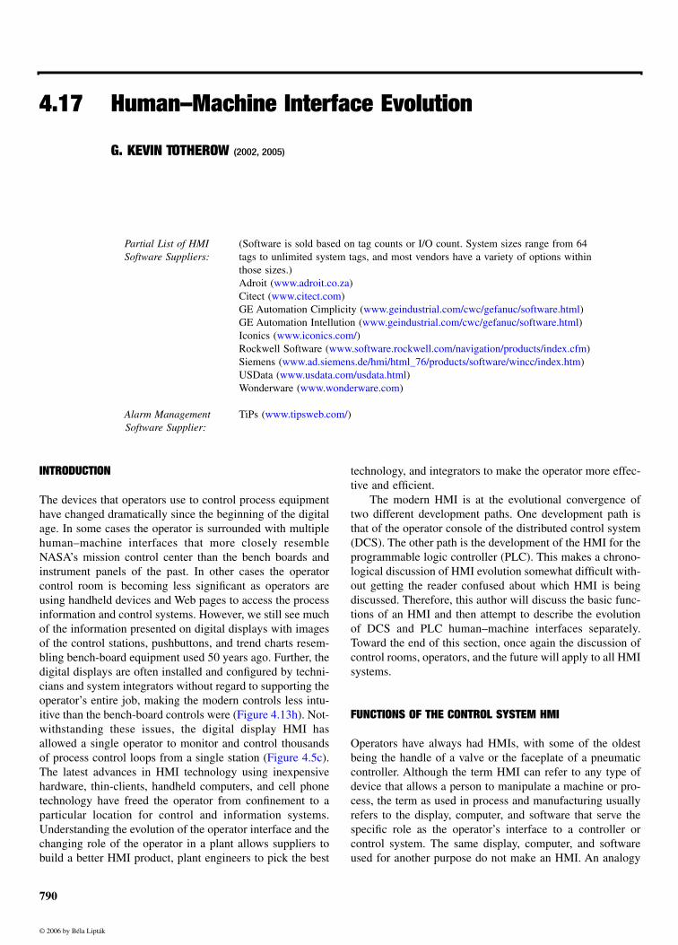
Most of the controller was hidden from view, and thepart of the controller that was above the bench board for theoperator to see and use was the controller faceplate. Thisfaceplate displayed the process variable and provided accessto change the mode, set point, or output to the loop. Thecontrollers were mounted on the panel in logical clustersbased on the process group. Figure 4.17b shows a power
TABLE 4.17aDefinitions of HMI Terminology
Term Definition
HMI Human–machine interface. Computer hardware and software that allows operators to interface with the control system.
CRT HMI Cathode ray tube HMI. The term is specifically used where there is a transition from hand stations to the HMI.
DCS HMI Proprietary HMI from DCS vendors that is optimized to work with the DCS.
GUI Graphical user interface. General computer term for software that allows graphical interaction with the computer.
Open HMI
HMI built on PC hardware and Windows operating system for general use. Not specific to any hardware.
Operator’swindow
Open HMI that incorporates information systems and controls.
PLC HMI Proprietary HMI from PLC vendors that is optimized to work with the PLC.
FIG. 4.17bPower boiler control panel circa 1984, picture by Jim Mahoney. Nineteen hand stations are in the bottom center of the panel. Four aredigital stations for a Bailey Net90 DCS, the other fifteen are pneumatic controllers.
© 2006 by Béla Lipták
792 Control Room Equipment
boiler control panel with pneumatic controllers to the rightand a few electronic trend units and DCS hand stations onthe left.
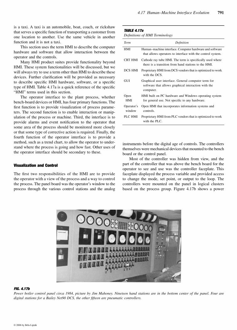
The HMI provides the same functionality to monitor andcontrol the process in a newer, highly customized, and con-stantly evolving package. The HMI makes it possible toincrease the number of control loops and process informationpresented to the operator many times higher than could bemounted in a control panel. A configurable display also givesthe ability to present the information to the operator in manyand various ways. Figure 4.17c shows a very simplisticgraphical operator interface with the controller hand stationsimplemented on the HMI.
Process Alarming
The third responsibility of the operator’s HMI is generation,annunciation, and manipulation of process and system alarms.Prior to the digital control age, generation of the alarm wasthe sole function of a switch in the field to determine whethera process parameter such as a pressure or temperatureexceeded specifications. A backlit light box with translucentwindow panels with the alarm written on the panel, called anannunciator, is the operator’s indication of the alarm. Thediscrete alarms were wired from switches to the annunciatorto provide a visual and audible alarm for serious processupsets or failures.
The annunciator allowed the operator to manipulate thealarm by silencing the audible portion or acknowledging thealarm. Alarming process parameters with an annunciatorpanel is very straightforward—install and calibrate theproper switch in the process, and wire the switch contact toa power source and to the annunciator panel. Of course, thealarms were expensive because of the required field installa-tion of switches and wiring. Also, there was a finite amount
of wall space in a control room to install annunciator panels,but on the positive side there were very few nuisance alarms.
The modern HMI generates process alarms from the ana-log process variable or a discrete input from the controlsystem. The HMI displays, stores, and manages the alarms.Process switches are not needed to provide process alarms,and the number of alarms that can be generated is virtuallyunlimited. The modern HMI makes process alarms cheap andeasy to implement, thus allowing engineers and managers tocreate nuisance alarms at an unprecedented rate.
Management of process alarms through silencing,acknowledging, and summarizing is now a primary functionof the HMI. Advanced alarm management, organization, andanalysis are distinguishing features among HMI products.
Trending
Long before the digital control system age, operators dependedon pen recorders to tell then what the process was currentlydoing and also the trend of the process variable. Analog penrecorders were set up to record the process at variable rates tomake the chart show the process trend for a certain numberof previous hours. The resolution of the recorder was inverselyproportional to the amount of time the recorder captured onpaper. Getting the proper balance of time and resolution onthe recorder was very important to helping the operator under-stand the direction and rate of change of the process. Recorderpaper was changed as necessary and kept on file to enableprocess engineers and managers to look at the history of thecontrol parameter.
The first digital display HMI immediately had provisionsfor keeping a history and the capability to provide the oper-ator with trending to replace the chart recorder. The trendingis very similar to the chart recorders—the data are collectedat a rate that will balance resolution with the total trend time.
FIG. 4.17cGroup display of hand-station faceplates on a Bailey Net90 HMI circa 1985. Photograph provided by Jim Mahoney.
© 2006 by Béla Lipták

4.17 Human–Machine Interface Evolution 793
However, unlike with the chart recorder, the operator cannotchange the paper and store an unlimited amount of processhistory.
Most of the control system and HMI companies abdicatethe long-term historical systems to others, choosing insteadto provide medium- to short-term trending for operators only.This decision is still reflected in many HMI products, whereoperator history and trending are an integral function of theHMI, but long-term history for management or regulatorycompliance is not.
DCS CONSOLES
The first companies offering digital display operator consolesfor process controls are the DCS companies, beginning withHoneywell in 1975 with the TDC 2000.1 This was followedclosely by several other major manufacturers of control prod-ucts. The introduction of a graphical user interface (GUI)display as the operator HMI is a technology leap destined tochange the way many industries operate. Yet many operatorsand some engineers feel more comfortable operating the pro-cess from a digital representation of their own older processcontroller faceplate than from a graphic of the process.
The faceplate is familiar to the operators, provides all ofthe detail about the controller and the control loop, and iseasily implemented by engineers. The problem with usingthe faceplate from the HMI is that the operator often had amuch better intuitive feel for finding the right controller andresponding quickly to upsets with the bench-board controlsas compared to navigating through various displays ofscreens to find the right controller.
Custom process graphics, or mimic displays, showingrepresentations of pumps, motors, vessels, agitators, heaters,and other process equipment along with good overview dis-plays and standards for navigation make controlling largeprocesses from the HMI display much more intuitive foroperators.
In 1983, Savannah Electric and Power Company bought aBailey Net90 DCS to replace pneumatic boiler controls and,like many others, chose to only replace pneumatic controllerson the bench board with rows of digital hand stations connectedto the DCS. Figure 4.17d shows digital hand stations for aBailey Net90 mounted in a panel beside pneumatic controllers.
The Bailey OIU (operator interface unit) displaying pro-cess graphics and graphical representations of the hand sta-tion faceplates sits beside the operator bench board. The logicof the transition is that the operators are accustomed to con-trolling the process by controller faceplates, and processgraphics are new and will take time to learn. The expense ofredesigning the control room to make the HMI useful as theprimary interface is also a large factor in a phased approachto introducing the HMI.
At Savannah Electric, the HMI offers more informationthan the hand stations show, and the operator can sit in one
position to control and monitor the boiler and auxiliaries.Eventually, the operators use the HMI as their primary controlinterface.
DCS Console Graphic Standards
The early DCS console was built specifically for a singlecontrol system. Controller faceplates were standard graphicalobjects that looked and functioned like bench-board handstations. The most popular early displays were the faceplate,group, and area.1 The faceplate is the graphical representationof the hand station with all of the process information andloop control. The group display is a display showing four toeight faceplates in a little less detail. The area display is anoverview of many process variables that allows operators toquickly see whether the processes are stable. DCS mimicdisplays are the highly customized displays that operators like.
Mimic displays show graphical illustrations of the pro-cess with process information. Good mimic displays andgood overview pages that show only the most pertinent infor-mation about large process areas make the operators moreefficient. The HMI is so flexible and easy to change thatcompanies quickly realized that they needed to adopt at leastbasic standards for building these custom displays to ensureconsistency between engineers and projects.
Suddenly, industry and plant questions arose as towhether a red motor indicated the motor is energized or didit mean the motor is stopped? Does a green valve indicateopen, closed, or deenergized? The standards that most com-panies adopted include object size, conditional colors, pro-cess colors, screen navigation, and screen density guidelines.Organizations such as the ISA developed standards for oper-ator displays that include the items above and many more.3
FIG. 4.17dFour Bailey Net90 DCS hand stations mounted beside two pneumaticcontrollers, circa 1984. Photograph courtesy of Jim Mahoney.
© 2006 by Béla Lipták
794 Control Room Equipment
The standard displays for most DCS operator consolesinclude:
• Process graphic displays• Faceplates• System diagnostic graphics• Controller tuning pages• A list or hierarchy of displays• Alarm summary page• Trending pages
Screen/Page Navigation and Item Selection Navigating be-tween DCS displays on first- and second-generation systemsand selecting the controllers on the display is highly custom-ized with custom keyboards to make the operator efficient.Generally, the only “mouse” in the control room at this time(early to mid-1980s) was the real one that shorts out controlloops while eating insulation off the cables. The commonmethods of screen navigation included:
• Touch screen. Touch the object to select it. Thisincluded paging objects.
• Direct screen reference (DSR) numbers from one dis-play to the next. The DSR selected the display.
• Direct screen reference (DSR) numbers from the dis-play list. Each display on the display list was assigneda DSR number. Selecting that DSR from the displaylist would take the operator to the display.
• Configured forward and backward display keys. Eachdisplay could have configured forward and backwarddisplays to navigate logically.
• Show detail keys. Devices selected could bring up adetailed display of the object or controller.
• Defined function keys. Console keys that change topreconfigured display.
• Trackballs. The trackball was mounted in the customkeyboard and manipulated a pointing device on thedisplay.
More vendors used a mouse or trackball and fewer use cus-tom keyboards with later revisions of the DCS operator con-sole, although the best operators swear they are more efficientwith the older custom keyboards and DSRs on the display.
DCS HMI Redundancy
Many managers and engineers were worried about operatingpotentially dangerous processes through a computer whenthe DCS first arrived on the scene. DCS vendors worked hardon the technical issues of redundancy and selling the conceptof the HMI to industries that liked the idea of direct manip-ulation of hand stations on controllers.
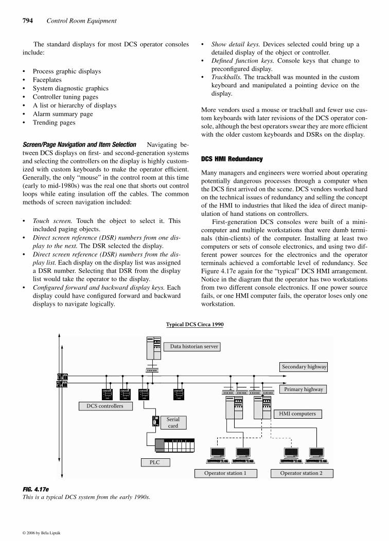
First-generation DCS consoles were built of a mini-computer and multiple workstations that were dumb termi-nals (thin-clients) of the computer. Installing at least twocomputers or sets of console electronics, and using two dif-ferent power sources for the electronics and the operatorterminals achieved a comfortable level of redundancy. SeeFigure 4.17e again for the “typical” DCS HMI arrangement.Notice in the diagram that the operator has two workstationsfrom two different console electronics. If one power sourcefails, or one HMI computer fails, the operator loses only oneworkstation.
FIG. 4.17eThis is a typical DCS system from the early 1990s.
Data historian server
DCS controllers
Serialcard
PLC
Operator station 1 Operator station 2
HMI computers
Primary highway
Secondary highway
Typical DCS Circa 1990
© 2006 by Béla Lipták
4.17 Human–Machine Interface Evolution 795
The first-generation consoles from vendors such as FisherControls and Bailey Controls could be configured with up to2,500 points. Second-generation consoles could handle10,000 points. The HMI had to provide operators with anefficient interface to the DCS with the number of displaysand point count necessary for the application yet still refreshquickly. A common console specification demands a maxi-mum screen update time of 5 seconds and a refresh rate of3 seconds. The console is a very large part of the selectioncriteria for a DCS for many customers.
DCS HMI Chronological Evolution
1975–1985 The various HMI offerings use proprietaryhardware and software and, like other systems of that gener-ation, hardware and software are inseparable. Nowhere is thismore evident than in the HMI keyboards. The keyboardscontain rows and rows of special fixed keys to start, stop,open, and close the selected devices and acknowledge alarmsand silence horns. The keyboards also have configurable keysfor display navigation and special functions.
Finally, the HMI includes function keys that change func-tion with each display to help make the operator more effi-cient. Each DCS vendor has different ideas and standards fortheir HMI, but all approach the operator interface as the totalsolution to replace the bench board. The DCS HMI includescabinets with room for mounting push buttons or telephones,wedge-shape tabletops to mount between HMI consoles tocurve the console, matching tabletops for writing surfaces,and even chairs.
1986–1995 Later generations of these proprietary HMIproducts show incredible integration with other componentsin the “system.” Most DCS HMI products incorporate dis-tributed alarming, console redundancy, and a common con-figuration database for controllers and consoles. System easeof use is a theme. One price for this tight integration ofproprietary systems is that by the second or third generationof DCS offerings, communication problems exist betweenvintages. The first-generation HMI cannot always communi-cate with second- or third-generation controllers and third-generation HMI cannot always communicate with first- orsecond-generation controllers.
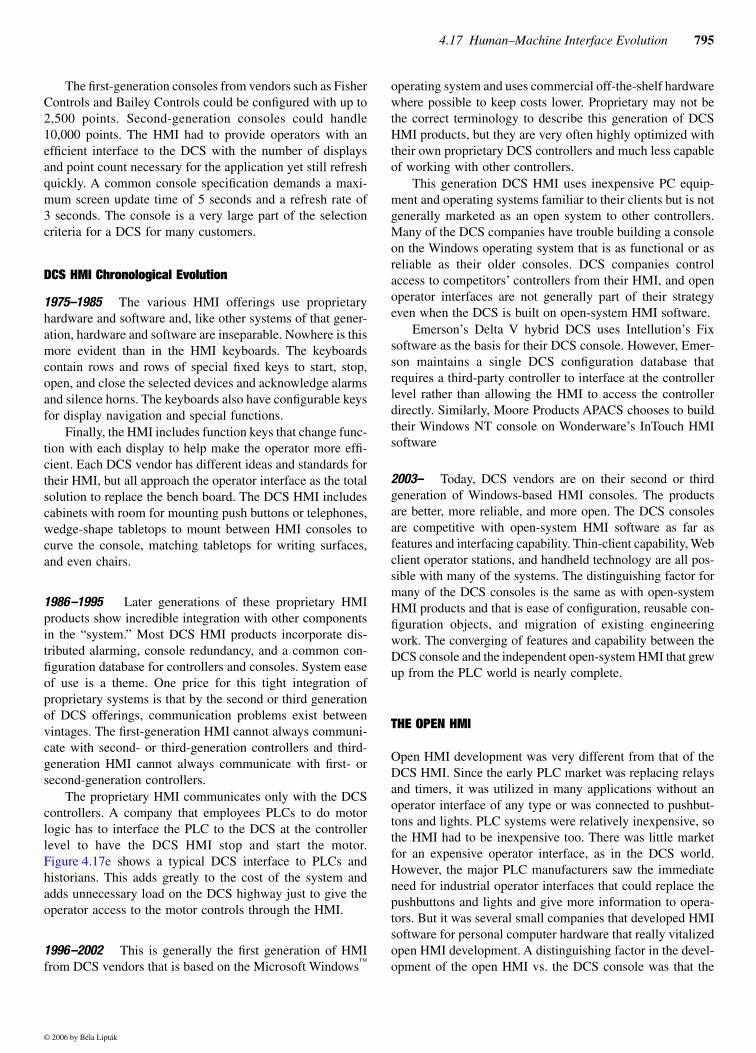
The proprietary HMI communicates only with the DCScontrollers. A company that employees PLCs to do motorlogic has to interface the PLC to the DCS at the controllerlevel to have the DCS HMI stop and start the motor.Figure 4.17e shows a typical DCS interface to PLCs andhistorians. This adds greatly to the cost of the system andadds unnecessary load on the DCS highway just to give theoperator access to the motor controls through the HMI.
1996–2002 This is generally the first generation of HMIfrom DCS vendors that is based on the Microsoft Windows™
operating system and uses commercial off-the-shelf hardwarewhere possible to keep costs lower. Proprietary may not bethe correct terminology to describe this generation of DCSHMI products, but they are very often highly optimized withtheir own proprietary DCS controllers and much less capableof working with other controllers.
This generation DCS HMI uses inexpensive PC equip-ment and operating systems familiar to their clients but is notgenerally marketed as an open system to other controllers.Many of the DCS companies have trouble building a consoleon the Windows operating system that is as functional or asreliable as their older consoles. DCS companies controlaccess to competitors’ controllers from their HMI, and openoperator interfaces are not generally part of their strategyeven when the DCS is built on open-system HMI software.
Emerson’s Delta V hybrid DCS uses Intellution’s Fixsoftware as the basis for their DCS console. However, Emer-son maintains a single DCS configuration database thatrequires a third-party controller to interface at the controllerlevel rather than allowing the HMI to access the controllerdirectly. Similarly, Moore Products APACS chooses to buildtheir Windows NT console on Wonderware’s InTouch HMIsoftware
2003– Today, DCS vendors are on their second or thirdgeneration of Windows-based HMI consoles. The productsare better, more reliable, and more open. The DCS consolesare competitive with open-system HMI software as far asfeatures and interfacing capability. Thin-client capability, Webclient operator stations, and handheld technology are all pos-sible with many of the systems. The distinguishing factor formany of the DCS consoles is the same as with open-systemHMI products and that is ease of configuration, reusable con-figuration objects, and migration of existing engineeringwork. The converging of features and capability between theDCS console and the independent open-system HMI that grewup from the PLC world is nearly complete.
THE OPEN HMI
Open HMI development was very different from that of theDCS HMI. Since the early PLC market was replacing relaysand timers, it was utilized in many applications without anoperator interface of any type or was connected to pushbut-tons and lights. PLC systems were relatively inexpensive, sothe HMI had to be inexpensive too. There was little marketfor an expensive operator interface, as in the DCS world.However, the major PLC manufacturers saw the immediateneed for industrial operator interfaces that could replace thepushbuttons and lights and give more information to opera-tors. But it was several small companies that developed HMIsoftware for personal computer hardware that really vitalizedopen HMI development. A distinguishing factor in the devel-opment of the open HMI vs. the DCS console was that the
© 2006 by Béla Lipták
796 Control Room Equipment
open HMI is not an integral part of a proprietary controlsystem.
Open HMI Display Standards
Open HMI software is extremely versatile, providing a cost-effective operator HMI to a stand-alone machine or a net-worked series of many operator stations for a large systemof many controllers. That versatility works against the openHMI in terms of configuration standards. The open HMIsoftware companies cannot foresee how the HMI will be usedby the purchaser. The open HMI companies follow theMicrosoft business model of supplying shrink-wrapped soft-ware for their customers to build into a functional HMI fortheir particular installation. The organization of process infor-mation and the configuration standards for the open HMIfalls entirely to system integrators, engineers, and endusers—with mixed results.
Information on the ergonomics of human factors such asposition of the chair, screen glare, and others is abundant.There is less information readily available on specific guide-lines to help engineers organize the information and build aneffective HMI. The ISA has a document, ISA-TR77.60.04-1996, for fossil fuel plants that provides some guidelines thatare common to all process industries. The problem is thatmany companies implementing medium to small projectsnever dedicate resources to human-factors engineering andestablishing HMI standards.
Documentation
Documentation is defined in this section to include installa-tion, configuration, backup, and change control documenta-tion. Documentation is a weak point for the open HMI whencompared to any proprietary system. The first weakness isthat the hardware, software, network, and configuration areindividual components from different companies. The engi-neers who install and configure the open HMI must providethe documentation for the HMI system. The open HMI soft-ware companies provide software documentation, configura-tion training, and configuration examples and tips to theirusers. The software company cannot know the system hard-ware or the configuration application, leaving the end userand engineer responsible for documentation of the system.
The second area of documentation weakness for the openHMI is the configuration backup and change control docu-mentation. The DCS prescribed database backup procedures,and most of the configuration systems automatically docu-mented database changes. The configuration backup of a PCfile such as an HMI application is intuitively easy, but changecontrol documentation is not. Third-party software productssuch as MDT’s AutoSave and GE’s Cimplicity Manager fillthis void with software that limits access to the HMI or PLCconfiguration and maintains a log of the changes that aremade to the HMI and PLC software packages.
Open HMI Evolution Chronology
1980s Early open or independent HMI products are writtento operate on all of the various computers and workstationsof the day on all of the various operating systems. It is theoffice PC, however, that provides the basic HMI capabilityin an inexpensive package. Microsoft releases the Windows3.1 operating system for the PC in the 1980s, and with eachsuccessive release it is more apparent that Windows is theplatform of choice for the open HMI. This is the time whenmany of the first computer-based HMI products such as Intel-lution, USData, and Wonderware began to fill a void in man-ufacturing control systems.
1990–1997 The PLC is now a very powerful logic control-ler capable of PID control and processor redundancy. Thelow price of the PLC and open HMI make them competitivein the process industry over most of the “mini-DCS” plat-forms that are available. Technology increases and low costcontinue to bring the PLC and open HMI into larger servicein the process industries and particularly in supervisory con-trol and data acquisition (SCADA) applications. The openHMI continues increasing in functionality compared to theDCS HMI, although many of the major DCS players scoffat suggestions of an HMI based on an Intel PC runningWindows.
Microsoft releases Windows NT 3.5 in 1994, WindowsNT 3.51 in 1995, and Windows NT 4.0 in 1996.4 Most ofthe open HMI companies upgrade their software to the cur-rent releases from Microsoft, and with each release comenew features and arguably better stability. PLC companiesrelease open HMI software products at this time to capitalizeon the burgeoning market for HMI products.
Major DCS vendors stop scoffing at the suggestion ofutilizing PC hardware and the Windows operating systemtoward the end of this time period and begin projects to createPC-based operator stations.
1997–2001 The major open HMI companies such asIntellution, Rockwell, and Wonderware continue to expandHMI functionality as computer hardware becomes morecapable of providing statistical process control (SPC), rec-ipe management, soft control capability, and a host of othercapabilities.
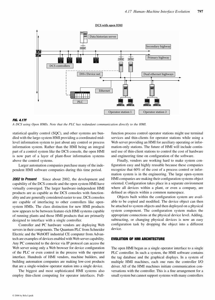
The open HMI begins to look even more impressive forprocess systems when several of the leading HMI companiesintroduce software supporting client–server architecture anddistributed alarming. The open HMI can act as a common,integrated HMI for all control systems at a plant. Figure4.17f shows the open HMI accessing data from multiple tagservers.
Through acquisition and partnering the open HMI, com-panies also begin the drive to integrate their HMI with a suiteof software products to provide better information to theentire corporation. Process data historians, execution sys-tems, Web-enabled clients, downtime tracking systems,
© 2006 by Béla Lipták
4.17 Human–Machine Interface Evolution 797
statistical quality control (SQC), and other systems are bun-dled with the large-system HMI providing a coordinated mid-level information system to just about any control or processinformation system. Rather than the HMI being an integralpart of a control system like the DCS console, the open HMIis now part of a layer of plant-floor information systemsabove the control systems.
Larger automation companies purchase many of the inde-pendent HMI software companies during this time period.
2002 to Present Since about 2002, the development andcapability of the DCS console and the open system HMI havevirtually converged. The larger hardware-independent HMIproducts are as capable as the DCS consoles with function-ality and are generally considered easier to use. DCS consolesare capable of interfacing to other controllers like open-system HMIs. The class distinction for new HMI productsnow appears to be between feature-rich HMI systems capableof running plants and those HMI products that are primarilydesigned to interface with a single controller.
Controller and PC hardware vendors are deploying Webservers in their components. The Quantum PLC from SchneiderElectric and the WebOIT industrial CE computer from Advan-tech are examples of devices enabled with Web server capability.Any PC connected to the device via IP protocol can access theWeb server using only a Web browser for device configurationof the PLC or even control in the process with the operatorinterface. Hundreds of HMI vendors, machine builders, andbuilding automation companies are making low-cost productsthat are a single-window operator station into a single device.
The biggest and most sophisticated HMI systems alsoemploy thin-client computing for operator interfaces. Full-
function process control operator stations might use terminalservices and thin-clients for operator stations while using aWeb server providing an HMI for auxiliary operating or infor-mation-only stations. The future of HMI will include contin-ued use of thin-client stations to control the cost of hardwareand engineering time on configuration of the software.
Finally, vendors are working hard to make system con-figuration easy and highly reusable because these companiesrecognize that 60% of the cost of a process control or infor-mation system is in the engineering. The large open-systemHMI companies are making their configuration systems objectoriented. Configuration takes place in a separate environmentwhere all devices within a plant, or even a company, aredefined as objects within a common namespace.
Objects built within the configuration system are avail-able to be copied and modified. The device object can thenbe attached to system objects and then deployed on a physicalsystem component. The configuration system makes theappropriate connections at the physical device level. Adding,subtracting, or changing physical devices is now an easyconfiguration task by dropping the object into a differentdevice.
EVOLUTION OF HMI ARCHITECTURE
The open HMI began as a single operator interface to a singlePLC controller. In such a system, the HMI software containsthe tag database and the graphical displays. In a system ofmultiple HMI machines, each one runs the controller I/Odriver. All of the HMI machines initiate communication con-versations with the controller. This is a fine arrangement for asmall system but cannot support systems with many controllers
FIG. 4.17fA DCS using Open HMIs. Note that the PLC has redundant communication directly to the HMI.
Data historian server
Secondary highway
Primary highway
Dual ethernet highways
Operator station 2Operator station 1
PLC
Ethernet
DH+/Device net
DCS controllers
DCS with open HMI
© 2006 by Béla Lipták

798 Control Room Equipment
and HMI machines. The answer is a client–server architectureand remote tag access in the HMI.
The client–server architecture for the open HMI wasintroduced in the mid to late 1990s. The server machineconnects to the controller device or system. Multiple HMImachines act as clients accessing the tags in the one or moreservers. The client–server architecture improved the abilityof the open HMI to interface to multiple controllers andgreatly opened the door for the HMI to become the operator’swindow to information from any source.
The cost of buying and maintaining the HMI hardwareand software assets is high for large industrial plants. Theclient–server architecture described above still requires PChardware and HMI software at both the client and serverlocations. The next major development in HMI architecturaldesign is to reduce these costs by making the operator HMIa thin client. This architecture also requires upkeep of clientsoftware. The definition of a thin client is a client machinethat displays the operator HMI displays without applicationsoftware on the client.
The advantage of this architecture is the decreased costof system management, increased system maintainability, andlonger component life cycle since the thin client does littlework. There are two types of thin client systems: thin clientsthat display and interface to an instance of an application onterminal server and thin clients that display informationthrough a browser.
A terminal services thin client displays an HMI applica-tion session that is running in a Microsoft Terminal Server.The client box views and interfaces to the session through anEthernet TCP/IP network. This HMI architecture, shown inFigure 4.17g, enables every thin client to have a full-func-tioned HMI that is very fast using either Microsoft Remote
Desktop Protocol (RDP) or Citrix Independent ComputingArchitecture (ICA) protocol. This is an excellent way toenable wireless handheld computers.
Citrix MetaFrame software further enhances the archi-tecture by allowing server farms and server load balancing.Most DCS operator stations of the 1970s, 1980s, and early1990s were thin-client terminals displaying an instance ofthe program on the operator console computer. The operat-ing system was likely UNIX or VME, and the client wascalled a dumb terminal, but the concept of the thin clientis the same.
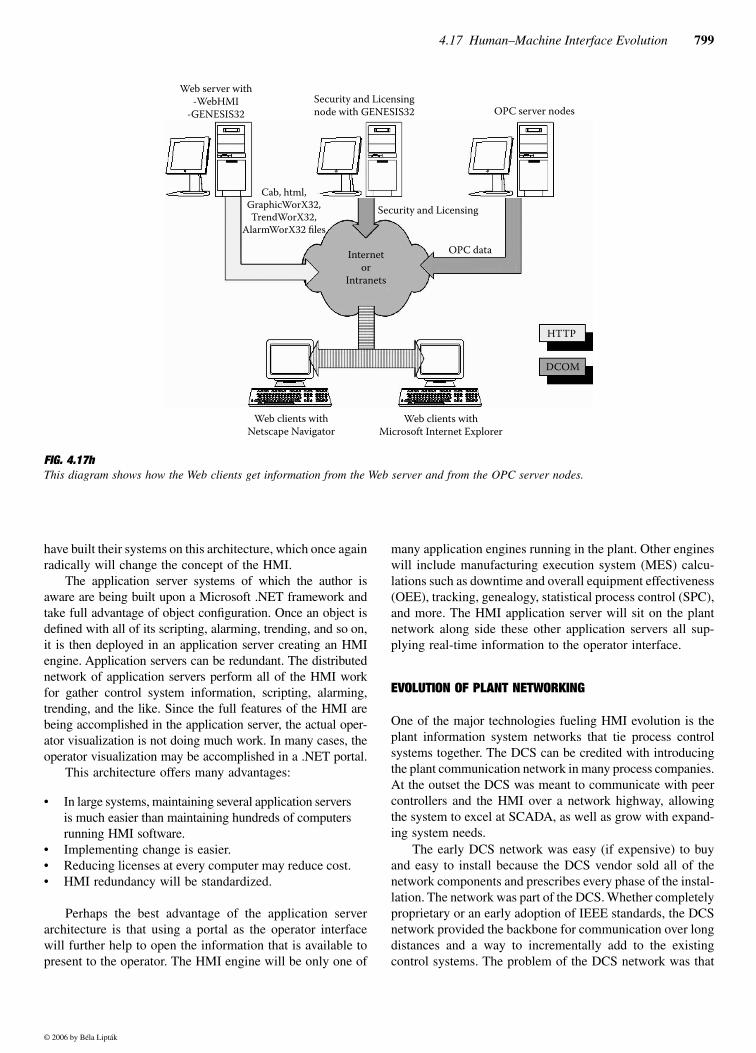
The second type of thin client is one that uses only anInternet browser to view the operator HMI from a Web server.Tim Donaldson, Marketing Manager for Iconics, an industrialautomation software company, describes how their WebHMIfunctions (see Figure 4.17h):
The Web publishing wizard publishes the graphics, trends,reports, and alarms to the Web server running WebHMI,Genesis32 software and Microsoft Personal Web Serveror Microsoft Internet Information Server (IIS). WebHMIuses communication technology that supports routers,switches, firewalls, virtual private networks (VPN). Anyclient PC with an Internet browser can point to the desiredWeb page on the server and the HTML page will load allnecessary components in the background providing a real-time OPC-enabled HMI.
The last architecture discussed in this section is the HMIapplication server. An HMI application server is built similarto the software application servers from companies such asSun Microsystems, IBM, and Oracle. By the time of thisprinting, Wonderware, Adroit, and possibly other companies
FIG. 4.17gThe architecture of thin-client open HMI on a traditional DCS.
Data historian server
Secondary highway
Primary highway
Primary andfail over terminal
servers
Operator station 2Operator station 1PLC
Ethernet
DCS controllers
�in-client HMI
© 2006 by Béla Lipták
4.17 Human–Machine Interface Evolution 799
have built their systems on this architecture, which once againradically will change the concept of the HMI.
The application server systems of which the author isaware are being built upon a Microsoft .NET framework andtake full advantage of object configuration. Once an object isdefined with all of its scripting, alarming, trending, and so on,it is then deployed in an application server creating an HMIengine. Application servers can be redundant. The distributednetwork of application servers perform all of the HMI workfor gather control system information, scripting, alarming,trending, and the like. Since the full features of the HMI arebeing accomplished in the application server, the actual oper-ator visualization is not doing much work. In many cases, theoperator visualization may be accomplished in a .NET portal.
This architecture offers many advantages:
• In large systems, maintaining several application serversis much easier than maintaining hundreds of computersrunning HMI software.
• Implementing change is easier.• Reducing licenses at every computer may reduce cost.• HMI redundancy will be standardized.
Perhaps the best advantage of the application serverarchitecture is that using a portal as the operator interfacewill further help to open the information that is available topresent to the operator. The HMI engine will be only one of
many application engines running in the plant. Other engineswill include manufacturing execution system (MES) calcu-lations such as downtime and overall equipment effectiveness(OEE), tracking, genealogy, statistical process control (SPC),and more. The HMI application server will sit on the plantnetwork along side these other application servers all sup-plying real-time information to the operator interface.
EVOLUTION OF PLANT NETWORKING
One of the major technologies fueling HMI evolution is theplant information system networks that tie process controlsystems together. The DCS can be credited with introducingthe plant communication network in many process companies.At the outset the DCS was meant to communicate with peercontrollers and the HMI over a network highway, allowingthe system to excel at SCADA, as well as grow with expand-ing system needs.
The early DCS network was easy (if expensive) to buyand easy to install because the DCS vendor sold all of thenetwork components and prescribes every phase of the instal-lation. The network was part of the DCS. Whether completelyproprietary or an early adoption of IEEE standards, the DCSnetwork provided the backbone for communication over longdistances and a way to incrementally add to the existingcontrol systems. The problem of the DCS network was that
FIG. 4.17hThis diagram shows how the Web clients get information from the Web server and from the OPC server nodes.
Web clients withNetscape Navigator
Web clients withMicrosoft Internet Explorer
DCOM
HTTP
OPC data
Security and LicensingCab, html,
GraphicWorX32,TrendWorX32,
AlarmWorX32 files
Internetor
Intranets
Web server with-WebHMI
-GENESIS32Security and Licensingnode with GENESIS32 OPC server nodes
© 2006 by Béla Lipták
800 Control Room Equipment
early DCS vendors did not foresee the vast amount of datathat customers would pull across those early highways tohigher-level systems.
PLCs commonly communicate on proprietary networksand fieldbus networks. PLC vendors and companies such asWoodhead SST build interface cards for the HMI to commu-nicate on these various fieldbus highways. In the 1990s manyprocess industries begin installing TCP/IP network systemsfor communication of personal computers. The inexpensivenetwork equipment and IT support make them the de factostandard for all communication networks at the HMI leveland above.
Development of industrial Ethernet networking equip-ment and widespread acceptance by equipment vendors isquickly making IP communication the standard down to theI/O level. This common and easy networking in processplants is a key factor in implementing large systems of openHMI operator stations.
EVOLUTION OF CONTROL ROOMS
The control rooms that predate the digital HMI have individ-ual process controller devices for valves, vanes, dampers, andother process control equipment that allow operators tomanipulate the controller output and set point. Push buttonsand lights are the operator interfaces for discrete relay logic.Individual instrument gauges, thermometers, strip chartrecorders, and sight glasses monitor process variables in the
control room and in the field. Annunciator panels providealarming and first-out indications.
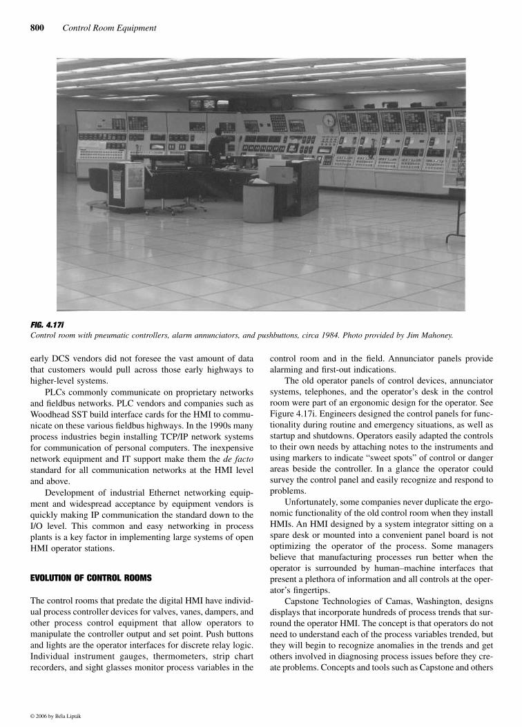
The old operator panels of control devices, annunciatorsystems, telephones, and the operator’s desk in the controlroom were part of an ergonomic design for the operator. SeeFigure 4.17i. Engineers designed the control panels for func-tionality during routine and emergency situations, as well asstartup and shutdowns. Operators easily adapted the controlsto their own needs by attaching notes to the instruments andusing markers to indicate “sweet spots” of control or dangerareas beside the controller. In a glance the operator couldsurvey the control panel and easily recognize and respond toproblems.
Unfortunately, some companies never duplicate the ergo-nomic functionality of the old control room when they installHMIs. An HMI designed by a system integrator sitting on aspare desk or mounted into a convenient panel board is notoptimizing the operator of the process. Some managersbelieve that manufacturing processes run better when theoperator is surrounded by human–machine interfaces thatpresent a plethora of information and all controls at the oper-ator’s fingertips.
Capstone Technologies of Camas, Washington, designsdisplays that incorporate hundreds of process trends that sur-round the operator HMI. The concept is that operators do notneed to understand each of the process variables trended, butthey will begin to recognize anomalies in the trends and getothers involved in diagnosing process issues before they cre-ate problems. Concepts and tools such as Capstone and others
FIG. 4.17iControl room with pneumatic controllers, alarm annunciators, and pushbuttons, circa 1984. Photo provided by Jim Mahoney.
© 2006 by Béla Lipták
4.17 Human–Machine Interface Evolution 801
deliver require “maximizing operator butt time” which in turnrequires that the HMI and auxiliary tools that the operatorneeds be designed to keep operators in front of their com-mand stations.
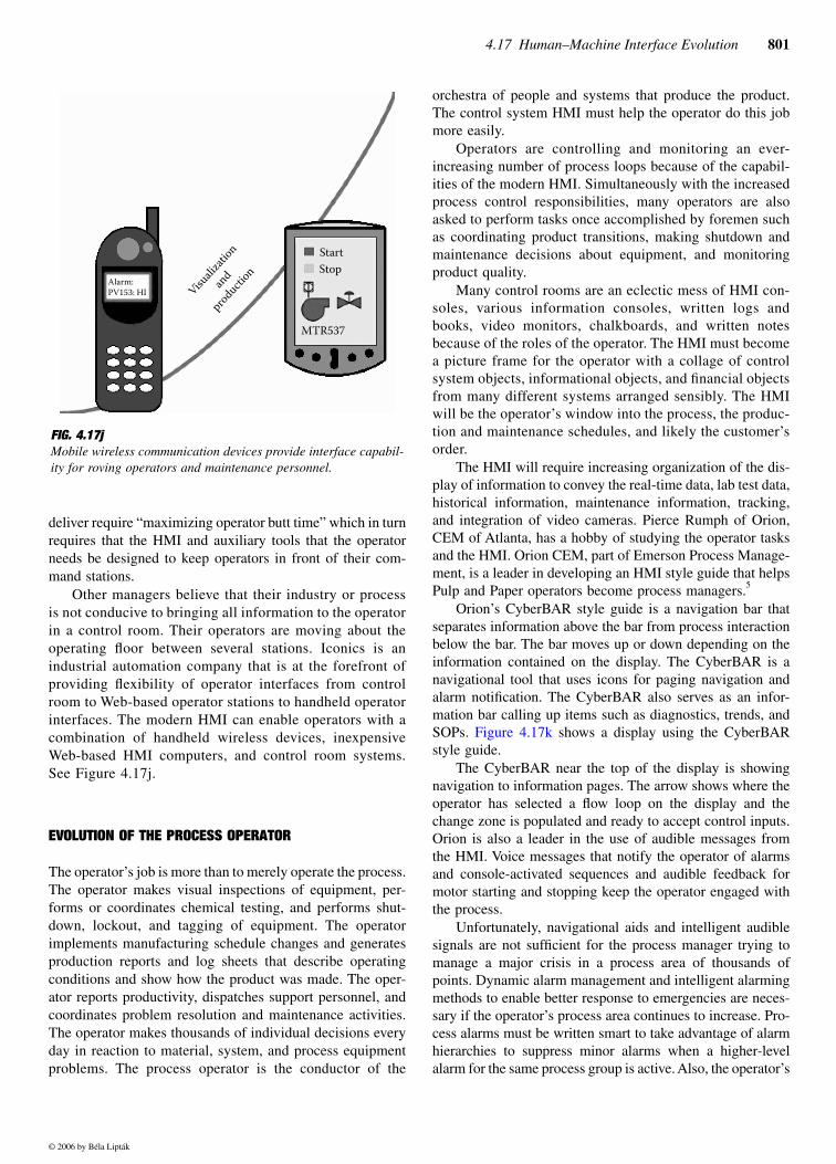
Other managers believe that their industry or processis not conducive to bringing all information to the operatorin a control room. Their operators are moving about theoperating floor between several stations. Iconics is anindustrial automation company that is at the forefront ofproviding flexibility of operator interfaces from controlroom to Web-based operator stations to handheld operatorinterfaces. The modern HMI can enable operators with acombination of handheld wireless devices, inexpensiveWeb-based HMI computers, and control room systems.See Figure 4.17j.
EVOLUTION OF THE PROCESS OPERATOR
The operator’s job is more than to merely operate the process.The operator makes visual inspections of equipment, per-forms or coordinates chemical testing, and performs shut-down, lockout, and tagging of equipment. The operatorimplements manufacturing schedule changes and generatesproduction reports and log sheets that describe operatingconditions and show how the product was made. The oper-ator reports productivity, dispatches support personnel, andcoordinates problem resolution and maintenance activities.The operator makes thousands of individual decisions everyday in reaction to material, system, and process equipmentproblems. The process operator is the conductor of the
orchestra of people and systems that produce the product.The control system HMI must help the operator do this jobmore easily.
Operators are controlling and monitoring an ever-increasing number of process loops because of the capabil-ities of the modern HMI. Simultaneously with the increasedprocess control responsibilities, many operators are alsoasked to perform tasks once accomplished by foremen suchas coordinating product transitions, making shutdown andmaintenance decisions about equipment, and monitoringproduct quality.
Many control rooms are an eclectic mess of HMI con-soles, various information consoles, written logs andbooks, video monitors, chalkboards, and written notesbecause of the roles of the operator. The HMI must becomea picture frame for the operator with a collage of controlsystem objects, informational objects, and financial objectsfrom many different systems arranged sensibly. The HMIwill be the operator’s window into the process, the produc-tion and maintenance schedules, and likely the customer’sorder.
The HMI will require increasing organization of the dis-play of information to convey the real-time data, lab test data,historical information, maintenance information, tracking,and integration of video cameras. Pierce Rumph of Orion,CEM of Atlanta, has a hobby of studying the operator tasksand the HMI. Orion CEM, part of Emerson Process Manage-ment, is a leader in developing an HMI style guide that helpsPulp and Paper operators become process managers.5
Orion’s CyberBAR style guide is a navigation bar thatseparates information above the bar from process interactionbelow the bar. The bar moves up or down depending on theinformation contained on the display. The CyberBAR is anavigational tool that uses icons for paging navigation andalarm notification. The CyberBAR also serves as an infor-mation bar calling up items such as diagnostics, trends, andSOPs. Figure 4.17k shows a display using the CyberBARstyle guide.
The CyberBAR near the top of the display is showingnavigation to information pages. The arrow shows where theoperator has selected a flow loop on the display and thechange zone is populated and ready to accept control inputs.Orion is also a leader in the use of audible messages fromthe HMI. Voice messages that notify the operator of alarmsand console-activated sequences and audible feedback formotor starting and stopping keep the operator engaged withthe process.
Unfortunately, navigational aids and intelligent audiblesignals are not sufficient for the process manager trying tomanage a major crisis in a process area of thousands ofpoints. Dynamic alarm management and intelligent alarmingmethods to enable better response to emergencies are neces-sary if the operator’s process area continues to increase. Pro-cess alarms must be written smart to take advantage of alarmhierarchies to suppress minor alarms when a higher-levelalarm for the same process group is active. Also, the operator’s
FIG. 4.17jMobile wireless communication devices provide interface capabil-ity for roving operators and maintenance personnel.
Alarm:PV153: HI Visu
alizat
ionan
dproducti
onStartStop
MTR537
© 2006 by Béla Lipták

802 Control Room Equipment
window must offer alarm disabling, silencing, and dynamicalarm level changes for various modes of operation for largehighly sophisticated process industries. TiPS Incorporated ofGeorgetown, Texas has several products such as LogMateand ACE to help capture and analyze process alarms to reduceconfusion during system upsets.
2005 AND BEYOND
Process control, the HMI, and the operator’s job function willcontinue to evolve. The physical choices for providing theoperator with a window into the process will continue toincrease and will include HMI stations distributed around theplant, consolidated control rooms, personal human–machineinterface devices such as handheld computers or cell phones,thin-client operator stations, and off-site human–machineinterfaces.
Process industries such as pulp and paper, foundries,utilities, chemical production, and others are very capitalintensive. Expensive process control equipment will not bereplaced without a great return on investment, so existing
controls will continue to be utilized for years, with newsystems integrating with old components and plant supportsystems.
Three initiatives that may have a large impact on theprocess operator HMI through 2010 will be integration ofdata from any system into the HMI, widely distributed andmobile operator windows, and the remote-from-site HMI.These technologies can integrate into existing plant systemsand utilize existing legacy systems, and they have the capac-ity to fundamentally change the way process systems areoperated in the future.
Distributed and Mobile Control
Is a control room the best place for the operator to controlthe process? Or should the operator move about the processarea?
The control room is a relatively new invention in manu-facturing. Prior to the DCS, many processes were run fromlocal panel boards. Coordination of the process control withthe panel boards was very difficult, and the central controlroom increased the plant control quality by allowing for
FIG. 4.17kHMI graphic using Orion’s CyberBAR display style guide. Selecting the flow on the graphic populates the change zone for operator entry.The CyberBAR near the top of the display is selected to navigate to information pages.
© 2006 by Béla Lipták
4.17 Human–Machine Interface Evolution 803
better coordination. The control systems are advancedenough that the control room is not needed to coordinate thecontrol in some cases.
HMI technology is capable of distributing inexpensiveoperator stations throughout a process area so that an operatorcan easily walk around the process and still be very close toan HMI. The operator can also use wireless handheld com-puter technology or even cell phone technology to managethe process.
Remote Operation of the Plant
If your main operator is in a central control room 100 yardsfrom the process today, why couldn’t the operator be 100miles from the process? Why not 1000 miles?
Control systems must be located within the propagationlimits of the signal wiring and process lines withoutextraordinary expenses. However, there are virtually nolonger limitations on distance away from the process forthe HMI.
Thin-client HMIs and the Internet now enable an oper-ator, or a backup “expert” operator, to be located anywherein the world. The few technical limitations associated withremote operation of the plant today are dissolving, andfuture discussions about the location of operators will bephilosophical.
The Future
Joey Rodems of InSource Solutions is a 10-year veteransales consultant of HMI software. In that time the HMI haschanged dramatically, but Mr. Rodems expects more and fasterchange.
The need for mobile production workers to stay connected,combined with the explosion of new wireless digital per-sonal communications devices, signals the eventual shiftof traditional fixed location HMI terminals in many pro-duction environments to the production worker’s secondarymeans of collaboration. Growing support for Web brows-ers, thin clients, smart phones, PDAs and tablet PCs is justthe tip of the iceberg. Over the next 5-10 years look forSCADA’s reach to extend beyond the HMI toward increas-ingly numerous and specialized personal communicationdevices. While these devices will provide a low-cost, nat-ural and effective means of event-based communications,strategically positioned fixed location HMI terminals willprovide rich analytical capabilities.
Human–machine interface is the subject of manyresearch projects in private industry, governments, and aca-demia. The work in virtual imaging is fascinating, but will itbe relevant in process control? The work by NASA on chang-ing HMI functionality associated with modes of operation6
could have industrial applications one day. Audio-based inter-action between humans and machines might prove to thegreatest benefits for the industrial HMI in the near future.
Auditory messages can be sent in parallel with visualsignals and can be spoken and received in hands-free oper-ations providing unmatched flexibility by any other I/Omethod.7 Engineers can implement auditory HMI in smallphases to augment conventional control. The technology ofaudio HMI is only beginning and like most technology, itwill be tested and refined in commercial applications longbefore it is introduced into industry.
However, the biggest gains in operational success asso-ciated with HMI may come not from the technology, but fromthe management and customization of HMI for the particularindustry, process, and individual operator. Distributed HMIdevices throughout the plant, personal HMI devices, ergo-nomically designed central control rooms, and perhaps audi-tory control can all be used with great success. Companiesthat implement or ignore the technology without a plan willprobably achieve much less than will companies that have aplan for operating the plant and provide the right HMI toolsto make it happen.
Increased priority on display design, information presen-tation, and operator interaction will provide a good return oninvestment. The process industries have more similarities intheir needs than differences. This creates opportunities fortoolkits from outside organizations and open HMI companiesto increase the efficiency and standards of HMI displays.
Jim Mahoney, a Project Specialist with ABB Automation,has over 20 years’ experience working with operator controlsystem interfaces. He has migrated control rooms from pneu-matic to digital, from first-generation HMI to the newestPC-based HMI. In a conversation about operator interfacesJim said,
The key to a good console is well-laid-out graphics thatproperly mimic the process, and ease in getting aroundthe multitude of screens. A state-of-the-art console withlousy graphics does not help operators do their job andcan actually be a major detriment.
Few experienced people will disagree with Mr. Mahoney,yet few realize that an HMI with mediocre displays helpsmake mediocre operators and an HMI with great displayshelps make great operators.
Finally, remember the four fundamental functions ofthe HMI software—visualization, control, alarming, andtrending—discussed at the beginning of this section? Thesefunctions were lumped together in software in the 1970sbecause of the available technology to produce an HMI at thattime. A future generation of HMI could see each of thesefunctions performed by different software or applicationservers and presented through a very thin operator’s windowthat is also looking at business systems, maintenance systems,and the company stock price.
© 2006 by Béla Lipták

804 Control Room Equipment
References
1. Freely, J., Merrit, K., Ogden, T., Studebaker, P., and Waterbury, B.,“The Rise of Distributed Control,” Control Magazine, December1999.
2. Galitz, W. The Essential Guide to User Interface Design, New York:John Wiley & Sons, 1997.
3. ISA-TR77.60.04-1996, “Fossil Fuel Power Plant Human–MachineInterface—CRT Displays,” approved May 24, 1996.
4. Business Week Online, February 22, 1999.
5. Rumph, H.P., “Improved Information Interfacing Turns Operators intoEffective Process Managers,” Pulp & Paper, August 1998.
6. Degani, A., Shafto, M., and Kirlik, A., “Modes in Human––MachineSystems: Review, Classification, and Application,” Human FactorsResearch and Technology Web page, NASA, http://human-factors.arc.nasa.gov, 2001.
7. Stephanidis, C., and Sfyrakis, M., “Current Trends in Man–MachineInterfaces: Potential Impact on People with Special Needs,” In Patric,R., and Roe, W. (Eds.), Telecommunications for All, Brussels: ECSC-EC-EAEC, 1995.
© 2006 by Béla Lipták