4.1 44 m Prepreg Blades - Windpark · PDF fileVestas to recipient as to this general...
80
Document no.: 961763 V02 Weight, Dimensions and Centre of Gravity of 44 m Blades Technical Data Date: 2010-09-27 Issued by: Technology R&D Class: 1 Type: T09 - Manual Page 3 of 3 Vestas Wind Systems A/S · Alsvej 21 · 8940 Randers SV · Denmark · www.vestas.com 4 Technical Data Figure 4-1: 44 m blade. 4.1 44 m Prepreg Blades Component L [mm] W hj [mm] H [mm] L c [mm] L cg [mm] W [kg] Blades 44000 1800 3512 9000 11200 6700 Blades including transport frames (HJ) 44150 2440 3300 9000 11700 7900 Table 4-1: Technical data 44 m prepreg blade. 4.2 44 m Wood Carbon Blades Component L [mm] W hj [mm] H [mm] L c [mm] L cg [mm] W [kg] Blades 44000 1800 3499 9000 13000 7050 Blades including transport frames (HJ) 44150 2440 3300 9000 13500 8250 Table 4-2: Technical data 44 m wood carbon blade. R.1000
Transcript of 4.1 44 m Prepreg Blades - Windpark · PDF fileVestas to recipient as to this general...

Document no.: 961763 V02 Weight, Dimensions and Centre of Gravity of 44 m
Blades
Technical Data
Date: 2010-09-27
Issued by: Technology R&D Class: 1
Type: T09 - Manual Page 3 of 3
Vestas Wind Systems A/S · Alsvej 21 · 8940 Randers SV · Denmark · www.vestas.com
4 Technical Data
Figure 4-1: 44 m blade.
4.1 44 m Prepreg Blades
Component L
[mm]
Whj
[mm]
H
[mm]
Lc
[mm]
Lcg
[mm]
W
[kg]
Blades
44000 1800 3512 9000 11200 6700
Blades
including
transport
frames (HJ)
44150 2440 3300 9000 11700 7900
Table 4-1: Technical data 44 m prepreg blade.
4.2 44 m Wood Carbon Blades
Component L
[mm]
Whj
[mm]
H
[mm]
Lc
[mm]
Lcg
[mm]
W
[kg]
Blades
44000 1800 3499 9000 13000 7050
Blades
including
transport
frames (HJ)
44150 2440 3300 9000 13500 8250
Table 4-2: Technical data 44 m wood carbon blade.
R.1000

Bijlage 2-2b –
Specificaties Vestas V90 – 3MW

Vestas Wind Systems A/S · Hedeager 42 · 8200 Aarhus N · Denmark · www.vestas.com
Restricted
Document no.: 0053-3707 V03
2016-05-06
General Description 3MW Platform
VESTAS PROPRIETARY NOTICE: This document contains valuable confidential information of Vestas Wind Systems A/S. It is protected by copyright law as an unpublished work. Vestas reserves all patent, copyright, trade secret, and other proprietary rights to it. The information in this document may not be used, reproduced, or disclosed except if and to the extent rights are expressly granted by Vestas in writing and subject to applicable conditions. Vestas disclaims all warranties except as expressly granted by written agreement and is not responsible for unauthorized uses, for which it may pursue legal remedies against responsible parties.

Document no.: 0053-3707 V03
General Description 3MW Platform
Table of contents
Date: 2016-05-06
Document owner: Platform Management Restricted
Type: T05 - General Description Page 2 of 43
Vestas Wind Systems A/S · Hedeager 42 · 8200 Aarhus N · Denmark · www.vestas.com
Table of contents
1 Introduction .......................................................................................................................... 5 2 General Description ............................................................................................................. 6 3 Mechanical Design ............................................................................................................... 7 3.1 Rotor ...................................................................................................................................... 7 3.2 Blades .................................................................................................................................... 7 3.3 Blade Bearing ........................................................................................................................ 7 3.4 Pitch System .......................................................................................................................... 8 3.5 Hub ........................................................................................................................................ 8 3.6 Main Shaft ............................................................................................................................. 8 3.7 Main Bearing Housing ............................................................................................................ 9 3.8 Main Bearing .......................................................................................................................... 9 3.9 Gearbox ................................................................................................................................. 9 3.10 Generator Bearings ................................................................................................................ 9 3.11 High-Speed Shaft Coupling .................................................................................................. 10 3.12 Yaw System ......................................................................................................................... 10 3.13 Crane ................................................................................................................................... 10 3.14 Towers ................................................................................................................................. 10 3.15 Nacelle Bedplate and Cover ................................................................................................ 11 3.16 Thermal Conditioning System .............................................................................................. 11 3.16.1 Generator and Converter Cooling ........................................................................................ 12 3.16.2 Gearbox and Hydraulic Cooling ........................................................................................... 12 3.16.3 Transformer Cooling ............................................................................................................ 12 3.16.4 Nacelle Cooling .................................................................................................................... 12 3.16.5 Optional Air Intake Hatches ................................................................................................. 12 4 Electrical Design ................................................................................................................ 12 4.1 Generator ............................................................................................................................ 12 4.2 Converter ............................................................................................................................. 13 4.3 HV Transformer ................................................................................................................... 13 4.3.1 IEC 50 Hz/60 Hz version ...................................................................................................... 14 4.3.2 Ecodesign - IEC 50 Hz/60 Hz version .................................................................................. 15 4.3.3 IEEE 60Hz version ............................................................................................................... 17 4.4 HV Cables ........................................................................................................................... 18 4.5 HV Switchgear ..................................................................................................................... 19 4.5.1 IEC 50/60Hz version ............................................................................................................ 20 4.5.2 IEEE 60Hz version ............................................................................................................... 21 4.6 AUX System ........................................................................................................................ 21 4.7 Wind Sensors ...................................................................................................................... 22 4.8 Vestas Multi Processor (VMP) Controller ............................................................................. 22 4.9 Uninterruptible Power Supply (UPS) .................................................................................... 22 5 Turbine Protection Systems.............................................................................................. 23 5.1 Braking Concept .................................................................................................................. 23 5.2 Short Circuit Protections ...................................................................................................... 24 5.3 Overspeed Protection .......................................................................................................... 24 5.4 Arc Detection ....................................................................................................................... 24 5.5 Smoke Detection ................................................................................................................. 24 5.6 Lightning Protection of Blades, Nacelle, Hub and Tower ...................................................... 24 5.7 EMC .................................................................................................................................... 25 5.8 Earthing ............................................................................................................................... 25 5.9 Corrosion Protection ............................................................................................................ 26 6 Safety .................................................................................................................................. 26 6.1 Access ................................................................................................................................. 26 6.2 Escape ................................................................................................................................. 26

Document no.: 0053-3707 V03
General Description 3MW Platform
Table of contents
Date: 2016-05-06
Document owner: Platform Management Restricted
Type: T05 - General Description Page 3 of 43
Vestas Wind Systems A/S · Hedeager 42 · 8200 Aarhus N · Denmark · www.vestas.com
6.3 Rooms/Working Areas ......................................................................................................... 27 6.4 Floors, Platforms, Standing, and Working Places ................................................................ 27 6.5 Service Lift ........................................................................................................................... 27 6.6 Climbing Facilities ................................................................................................................ 27 6.7 Moving Parts, Guards, and Blocking Devices ....................................................................... 27 6.8 Lights ................................................................................................................................... 27 6.9 Emergency Stop .................................................................................................................. 27 6.10 Power Disconnection ........................................................................................................... 27 6.11 Fire Protection/First Aid ....................................................................................................... 28 6.12 Warning Signs ..................................................................................................................... 28 6.13 Manuals and Warnings ........................................................................................................ 28 7 Environment ....................................................................................................................... 28 7.1 Chemicals ............................................................................................................................ 28 8 Design Codes ..................................................................................................................... 28 8.1 Design Codes – Structural Design ....................................................................................... 28 9 Colours ............................................................................................................................... 29 9.1 Nacelle Colour ..................................................................................................................... 29 9.2 Tower Colour ....................................................................................................................... 29 9.3 Blade Colour ........................................................................................................................ 30 10 Operational Envelope and Performance Guidelines ....................................................... 30 10.1 Climate and Site Conditions ................................................................................................. 30 10.2 Operational Envelope – Temperature and Altitude ............................................................... 30 10.3 Operational Envelope – Temperature and Altitude Derating in 3.45 MW Mode 0 ................. 31 10.4 Operational Envelope – Temperature and Altitude Derating in 3.6 MW Power
Optimized Mode (PO1) ........................................................................................................ 31 10.5 Operational Envelope – Temperature and Altitude Derating in 3.3 MW Load Optimized
Mode (LO1).......................................................................................................................... 32 10.6 Operational Envelope – Temperature and Altitude Derating in 3.0 MW Load Optimized
Mode (LO2).......................................................................................................................... 32 10.7 Operational Envelope – Grid Connection ............................................................................. 33 10.8 Operational Envelope – Reactive Power Capability in 3.45 MW Mode 0 .............................. 34 10.9 Operational Envelope – Reactive Power Capability in 3.45 MW Reactive Power
Optimized Mode (QO1) ........................................................................................................ 35 10.10 Operational Envelope – Reactive Power Capability in 3.6 MW Power Optimized Mode
(PO1) ................................................................................................................................... 36 10.11 Operational Envelope – Reactive Power Capability in 3.3 MW Load Optimized Mode
(LO1) ................................................................................................................................... 37 10.12 Operational Envelope – Reactive Power Capability in 3.0 MW Load Optimized Mode
(LO2) ................................................................................................................................... 38 10.13 Performance – Fault Ride Through ...................................................................................... 39 10.14 Performance – Reactive Current Contribution ...................................................................... 39 10.14.1 Symmetrical Reactive Current Contribution.......................................................................... 39 10.14.2 Asymmetrical Reactive Current Contribution ........................................................................ 40 10.15 Performance – Multiple Voltage Dips ................................................................................... 40 10.16 Performance – Active and Reactive Power Control .............................................................. 40 10.17 Performance – Voltage Control ............................................................................................ 41 10.18 Performance – Frequency Control ....................................................................................... 41 10.19 Distortion – Immunity ........................................................................................................... 41 10.20 Main Contributors to Own Consumption ............................................................................... 41 11 Drawings ............................................................................................................................ 42 11.1 Structural Design – Illustration of Outer Dimensions ............................................................ 42 11.2 Structural Design – Side View Drawing ................................................................................ 42 12 General Reservations, Notes and Disclaimers ................................................................ 43

Document no.: 0053-3707 V03
General Description 3MW Platform
Table of contents
Date: 2016-05-06
Document owner: Platform Management Restricted
Type: T05 - General Description Page 4 of 43
Vestas Wind Systems A/S · Hedeager 42 · 8200 Aarhus N · Denmark · www.vestas.com
Recipient acknowledges that (i) this General Description is provided for recipient's information
only, and, does not create or constitute a warranty, guarantee, promise, commitment, or other
representation (Commitment) by Vestas Wind Systems or any of its affiliated or subsidiary
companies (Vestas), all of which are disclaimed by Vestas and (ii) any and all Commitments by
Vestas to recipient as to this general description (or any of the contents herein) are to be
contained exclusively in signed written contracts between recipient and Vestas, and not within
this document.
See general reservations, notes and disclaimers (including, section 12, p. 43) to this general description.

Document no.: 0053-3707 V03
General Description 3MW Platform
Introduction
Date: 2016-05-06
Document owner: Platform Management Restricted
Type: T05 - General Description Page 5 of 43
Vestas Wind Systems A/S · Hedeager 42 · 8200 Arhus N · Denmark · www.vestas.com
1 Introduction
The 3MW Platform wind turbine configurations covered by this General
Description are listed below with designations according to IEC61400-22.
The maximum DIBt 2012 wind class is listed where applicable.
Please refer to the Performance Specification for the relevant turbine variant for
full wind class definition.
This General Description contains data and descriptions common among the
platform variants.
The variant specific performance can be found in the Performance Specifications
for the turbine variant and operational mode required.
Turbine Type
Class
Turbine Type | Operating Mode
V105-3.45 MW
V105-3.45 MW IEC IA 50/60 Hz | Mode 0
V105-3.45 MW IEC IA 50/60 Hz | Reactive Power Optimized Mode (QO1)
V105-3.6 MW IEC IA 50/60 Hz | Power Optimized Mode (PO1)
V105-3.3 MW IEC IA 50/60 Hz | Load Optimized Mode (LO1)
V105-3.0 MW IEC IA 50/60 Hz | Load Optimized Mode (LO2)
V112-3.45 MW
V112-3.45 MW IEC IA 50/60 H0z | Mode 0
V112-3.45 MW IEC IA 50/60 Hz | Reactive Power Optimized Mode (QO1)
V112-3.6 MW IEC IA 50/60 Hz | Power Optimized Mode (PO1)
V112-3.3 MW IEC IA 50/60 Hz | Load Optimized Mode (LO1)
V112-3.0 MW IEC IA 50/60 Hz | Load Optimized Mode (LO2)
V117-3.45 MW
V117-3.45 MW IEC IB + IIA 50/60 Hz | Mode 0
V117-3.45 MW IEC IB + IIA 50/60 Hz | Reactive Power Optimized Mode (QO1)
V117-3.6 MW IEC S + IIA 50/60 Hz | Power Optimized Mode (PO1)
V117-3.3 MW IEC IB + IIA 50/60 Hz | Load Optimized Mode (LO1)
V117-3.0 MW IEC IB + IIA 50/60 Hz | Load Optimized Mode (LO2)
V126-3.45 MW
Low Torque
(LTq)
V126-3.45 MW IEC IIB + IIIA 50/60 Hz LTq | Mode 0
V126-3.45 MW IEC IIB + IIIA 50/60 Hz LTq | Reactive Power Optimized Mode (QO1)
V126-3.3 MW IEC IIB + IIIA 50/60 Hz LTq | Load Optimized Mode (LO1)
V126-3.0 MW IEC IIB + IIIA 50/60 Hz LTq | Load Optimized Mode (LO2)
V126-3.45 MW
High Torque
(HTq)
V126-3.45 MW IEC IIA + IIIA 50/60 Hz HTq | Mode 0
V126-3.45 MW IEC IIA + IIIA 50/60 Hz HTq | Reactive Power Optimized Mode (QO1)
V126-3.6 MW IEC IIA + IIIA 50/60 Hz HTq | Power Optimized Mode (PO1)
V126-3.3 MW IEC IIA + IIIA 50/60 Hz HTq | Load Optimized Mode (LO1)
V126-3.0 MW IEC IIA + IIIA 50/60 Hz HTq | Load Optimized Mode (LO2)
V126-3.45 MW WZ 3 GK II TK A 50 Hz HTq | Mode 0
V126-3.45 MW WZ 3 GK II TK A 50 Hz HTq | Reactive Power Optim. Mode (QO1)

Document no.: 0053-3707 V03
General Description 3MW Platform
General Description
Date: 2016-05-06
Document owner: Platform Management Restricted
Type: T05 - General Description Page 6 of 43
Vestas Wind Systems A/S · Hedeager 42 · 8200 Arhus N · Denmark · www.vestas.com
Turbine Type
Class
Turbine Type | Operating Mode
V136-3.45 MW
V136-3.45 MW IEC IIIA 50/60 Hz | Mode 0
V136-3.45 MW IEC IIIA 50/60 Hz | Reactive Power Optimized Mode (QO1)
V136-3.3 MW IEC IIIA 50/60 Hz | Load Optimized Mode (LO1)
V136-3.0 MW IEC IIIA 50/60 Hz | Load Optimized Mode (LO2)
V136-3.45 MW WZ 2 GK II TK A 50 Hz | Mode 0
V136-3.45 MW WZ 2 GK II TK A 50 Hz | Reactive Power Optimized Mode (QO1)
Table 1-1: 3MW Platform turbine configurations covered.
2 General Description
Vestas 3MW Platform comprises a family of wind turbines sharing a common
design basis.
The 3MW Platform family of wind turbines includes V105-3.45 MW, V112-3.45
MW, V117-3.45 MW, V126-3.45 MW and V136-3.45 MW.
These turbines are pitch regulated upwind turbines with active yaw and a three-
blade rotor.
The wind turbine family provides rotors with a diameter in the range 105 m to 136
m and a rated output power of 3.45 MW.
A 3.45 MW Reactive Power Optimized Mode (QO1) is available for all variants.
A 3.6 MW Power Optimized Mode (PO1) is available for all variants except V136-
3.45 MW and V126-3.45 MW Low Torque (LTq).
Also, a 3.3 MW Load Optimized Mode (LO1) and a 3.0 MW Load Optimized
Mode (LO2) are available for all variants.
The wind turbine family utilises the OptiTip® concept and a power system based
on an induction generator and full-scale converter. With these features, the wind
turbine is able to operate the rotor at variable speed and thereby maintain the
power output at or near rated power even in high wind speed. At low wind speed,
the OptiTip® concept and the power system work together to maximise the power
output by operating at the optimal rotor speed and pitch angle.
Operating the wind turbine in the 3.45 MW Reactive Power Optimized Mode
(QO1) is achieved by applying an extended ambient temperature derate strategy
compared with 3.45 MW Mode 0 operation.
Operating the wind turbine in the 3.6 MW Power Optimized Mode (PO1) is
achieved by applying an extended ambient temperature derate strategy and
reduced reactive power capability compared with 3.45 MW Mode 0 operation.

Document no.: 0053-3707 V03
General Description 3MW Platform
Mechanical Design
Date: 2016-05-06
Document owner: Platform Management Restricted
Type: T05 - General Description Page 7 of 43
Vestas Wind Systems A/S · Hedeager 42 · 8200 Arhus N · Denmark · www.vestas.com
3 Mechanical Design
3.1 Rotor
The wind turbine is equipped with a rotor consisting of three blades and a hub.
The blades are controlled by the microprocessor pitch control system OptiTip®.
Based on the prevailing wind conditions, the blades are continuously positioned
to optimise the pitch angle.
Rotor V105 V112 V117 V126 V136
Diameter 105 m 112 m 117 m 126 m 136 m
Swept Area 8659 m2 9852 m2 10751 m2 12469 m2 14527 m2
Speed, Dynamic
Operation Range 8.3-17.6 8.1-17.6 6.7-17.5
5.9-16.3
(6.2-16.3) 5.6-15.3
Rotational
Direction Clockwise (front view)
Orientation Upwind
Tilt 6°
Hub Coning 4°
No. of Blades 3
Aerodynamic
Brakes Full feathering
Table 3-1: Rotor data
3.2 Blades
The blades are made of carbon and fibreglass and consist of two airfoil shells
bonded to a supporting beam.
Blades V105 V112 V117 V126 V136
Type Description Airfoil shells bonded to supporting
beam
Infused structural
airfoil shell
Blade Length 51.15 m 54.65 m 57.15 m 61.66 m 66.66 m
Material Fibreglass reinforced epoxy, carbon fibres and Solid Metal
Tip (SMT).
Blade Connection Steel roots inserted
Airfoils High-lift profile
Maximum Chord 4.0 m 4.1 m
Table 3-2: Blades data
3.3 Blade Bearing
The blade bearings are double-row four-point contact ball bearings.

Document no.: 0053-3707 V03
General Description 3MW Platform
Mechanical Design
Date: 2016-05-06
Document owner: Platform Management Restricted
Type: T05 - General Description Page 8 of 43
Vestas Wind Systems A/S · Hedeager 42 · 8200 Arhus N · Denmark · www.vestas.com
Blade Bearing
Lubrication Grease
Table 3-3: Blade bearing data
3.4 Pitch System
The turbine is equipped with a pitch system for each blade and a distributor
block, all located in the hub. Each pitch system is connected to the distributor
block with flexible hoses. The distributor block is connected to the pipes of the
hydraulic rotating transfer unit in the hub by means of three hoses (pressure line,
return line and drain line).
Each pitch system consists of a hydraulic cylinder mounted to the hub and a
piston rod mounted to the blade bearing via a torque arm shaft. Valves facilitating
operation of the pitch cylinder are installed on a pitch block bolted directly onto
the cylinder.
Pitch System
Type Hydraulic
Number 1 per blade
Range -10° to 90°
Table 3-4: Pitch system data
Hydraulic System
Main Pump Two redundant internal-gear oil pumps
Pressure 260 bar
Filtration 3 µm (absolute)
Table 3-5: Hydraulic system data.
3.5 Hub
The hub supports the three blades and transfers the reaction loads to the main
bearing and the torque to the gearbox. The hub structure also supports blade
bearings and pitch cylinders.
Hub
Type Cast ball shell hub
Material Cast iron
Table 3-6: Hub data
3.6 Main Shaft
The main shaft transfers the reaction forces to the main bearing and the torque to
the gearbox.
Document no.: 0053-3707 V03
General Description 3MW Platform
Mechanical Design
Date: 2016-05-06
Document owner: Platform Management Restricted
Type: T05 - General Description Page 9 of 43
Vestas Wind Systems A/S · Hedeager 42 · 8200 Arhus N · Denmark · www.vestas.com
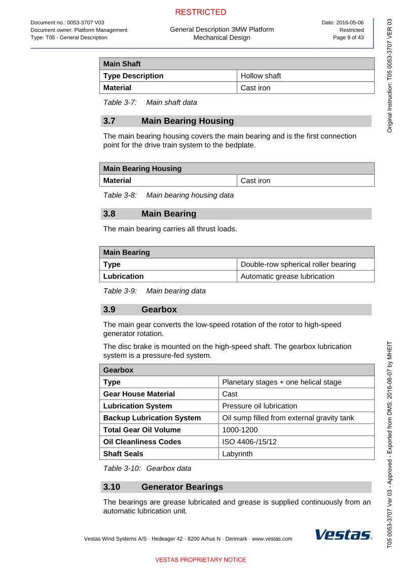
Main Shaft
Type Description Hollow shaft
Material Cast iron
Table 3-7: Main shaft data
3.7 Main Bearing Housing
The main bearing housing covers the main bearing and is the first connection
point for the drive train system to the bedplate.
Main Bearing Housing
Material Cast iron
Table 3-8: Main bearing housing data
3.8 Main Bearing
The main bearing carries all thrust loads.
Main Bearing
Type Double-row spherical roller bearing
Lubrication Automatic grease lubrication
Table 3-9: Main bearing data
3.9 Gearbox
The main gear converts the low-speed rotation of the rotor to high-speed
generator rotation.
The disc brake is mounted on the high-speed shaft. The gearbox lubrication
system is a pressure-fed system.
Gearbox
Type Planetary stages + one helical stage
Gear House Material Cast
Lubrication System Pressure oil lubrication
Backup Lubrication System Oil sump filled from external gravity tank
Total Gear Oil Volume 1000-1200
Oil Cleanliness Codes ISO 4406-/15/12
Shaft Seals Labyrinth
Table 3-10: Gearbox data
3.10 Generator Bearings
The bearings are grease lubricated and grease is supplied continuously from an
automatic lubrication unit.

Document no.: 0053-3707 V03
General Description 3MW Platform
Mechanical Design
Date: 2016-05-06
Document owner: Platform Management Restricted
Type: T05 - General Description Page 10 of 43
Vestas Wind Systems A/S · Hedeager 42 · 8200 Arhus N · Denmark · www.vestas.com
3.11 High-Speed Shaft Coupling
The coupling transmits the torque of the gearbox high-speed output shaft to the
generator input shaft.
The coupling consists of two 4-link laminate packages and a fibreglass
intermediate tube with two metal flanges.
The coupling is fitted to two-armed hubs on the brake disc and the generator hub.
3.12 Yaw System
The yaw system is an active system based on a robust pre-tensioned plain yaw-
bearing concept with PETP as friction material.
Yaw System
Type Plain bearing system
Material Forged yaw ring heat-treated.
Plain bearings PETP
Yawing Speed (50 Hz) 0.45°/sec.
Yawing Speed (60 Hz) 0.55°/sec.
Table 3-11: Yaw system data
Yaw Gear
Type Multiple stages geared
Ratio Total 944:1
Rotational Speed at Full Load 1.4 rpm at output shaft
Table 3-12: Yaw gear data
3.13 Crane
The nacelle houses the internal safe working load (SWL) service crane. The
crane is a single system hoist.
Crane
Lifting Capacity Maximum 800 kg
Table 3-13: Crane data
3.14 Towers
Tubular towers with flange connections, certified according to relevant type
approvals, are available in different standard heights. The towers are designed
with the majority of internal welded connections replaced by magnet supports to
create a predominantly smooth-walled tower.
Magnets provide load support in a horizontal direction and internals, such as
platforms, ladders, etc., are supported vertically (that is, in the gravitational
direction) by a mechanical connection. The smooth tower design reduces the

Document no.: 0053-3707 V03
General Description 3MW Platform
Mechanical Design
Date: 2016-05-06
Document owner: Platform Management Restricted
Type: T05 - General Description Page 11 of 43
Vestas Wind Systems A/S · Hedeager 42 · 8200 Arhus N · Denmark · www.vestas.com
required steel thickness, rendering the tower lighter compared to one with all
internals welded to the tower shells.
Available hub heights are listed in the Performance Specification for each turbine
variant. Designated hub heights include a distance from the foundation section to
the ground level of approximately 0.2 m depending on the thickness of the
bottom flange and a distance from tower top flange to centre of the hub of 2.2 m.
Towers
Type Cylindrical/conical tubular
Table 3-14: Tower structure data
3.15 Nacelle Bedplate and Cover
The nacelle cover is made of fibreglass. Hatches are positioned in the floor for
lowering or hoisting equipment to the nacelle and evacuation of personnel. The
roof section is equipped with wind sensors and skylights. The skylights can be
opened from inside the nacelle to access the roof and from outside to access the
nacelle. Access from the tower to the nacelle is through the yaw system.
The nacelle bedplate is in two parts and consists of a cast iron front part and a
girder structure rear part. The front of the nacelle bedplate is the foundation for
the drive train and transmits forces from the rotor to the tower through the yaw
system. The bottom surface is machined and connected to the yaw bearing and
the yaw gears are bolted to the front nacelle bedplate.
The crane girders are attached to the top structure. The lower beams of the
girder structure are connected at the rear end. The rear part of the bedplate
serves as the foundation for controller panels, the cooling system and
transformer. The nacelle cover is installed on the nacelle bedplate.
Type Description Material
Nacelle Cover GRP
Bedplate Front Cast iron
Bedplate Rear Girder structure
Table 3-15: Nacelle bedplate and cover data
3.16 Thermal Conditioning System
The thermal conditioning system consists of a few robust components:
The Vestas CoolerTop® located on top of the rear end of the nacelle. The
CoolerTop® is a free flow cooler, thus ensuring that there are no electrical
components in the thermal conditioning system located outside the
nacelle.
The Liquid Cooling System, which serves the gearbox, hydraulic systems,
generator and converter is driven by an electrical pumping system.
The transformer forced air cooling comprised of an electrical fan.

Document no.: 0053-3707 V03
General Description 3MW Platform
Electrical Design
Date: 2016-05-06
Document owner: Platform Management Restricted
Type: T05 - General Description Page 12 of 43
Vestas Wind Systems A/S · Hedeager 42 · 8200 Arhus N · Denmark · www.vestas.com
3.16.1 Generator and Converter Cooling
The generator and converter cooling systems operate in parallel. A dynamic flow
valve mounted in the generator cooling circuit divides the cooling liquid flow. The
cooling liquid removes heat from the generator and converter unit using a free-air
flow radiator placed on the top of the nacelle. In addition to the generator,
converter unit and radiator, the circulation system includes an electrical pump
and a three-way thermostatic valve.
3.16.2 Gearbox and Hydraulic Cooling
The gearbox and hydraulic cooling systems are coupled in parallel. A dynamic
flow valve mounted in the gearbox cooling circuit divides the cooling flow. The
cooling liquid removes heat from the gearbox and the hydraulic power unit
through heat exchangers and a free-air flow radiator placed on the top of the
nacelle. In addition to the heat exchangers and the radiator, the circulation
system includes an electrical pump and a three-way thermostatic valve.
3.16.3 Transformer Cooling
The transformer is equipped with forced-air cooling. The ventilator system
consists of a central fan, located below the converter and an air duct leading the
air to locations beneath and between the high voltage and low voltage windings
of the transformer.
3.16.4 Nacelle Cooling
Hot air generated by mechanical and electrical equipment is dissipated from the
nacelle by a fan system located in the nacelle.
3.16.5 Optional Air Intake Hatches
Specific air intakes in the nacelle can optionally be fitted with hatches which can
be operated as a part of the thermal control strategy. In case of lost grid to the
turbine, the hatches will automatically be closed.
4 Electrical Design
4.1 Generator
The generator is a three-phase asynchronous induction generator with cage rotor
that is connected to the grid through a full-scale converter. The generator housing
allows the circulation of cooling air within the stator and rotor. The air-to-water
heat exchange occurs in an external heat exchanger.
Generator
Type Asynchronous with cage rotor
Rated Power [PN] 3650 kW / 3800 kW
Frequency [fN] 0-100 Hz
Voltage, Stator [UNS] 3 x 750 V (at rated speed)
Number of Poles 4/6
Winding Type Form with VPI (Vacuum Pressurized Impregnation)

Document no.: 0053-3707 V03
General Description 3MW Platform
Electrical Design
Date: 2016-05-06
Document owner: Platform Management Restricted
Type: T05 - General Description Page 13 of 43
Vestas Wind Systems A/S · Hedeager 42 · 8200 Arhus N · Denmark · www.vestas.com
Generator
Winding Connection Star or Delta
Rated rpm 1450-1550 rpm
Overspeed Limit Acc.
to IEC (2 minutes)
2400 rpm
Generator Bearing Hybrid/ceramic
Temperature Sensors,
Stator
3 PT100 sensors placed at hot spots and 3 as back-
up
Temperature Sensors,
Bearings
1 per bearing
Insulation Class F or H
Enclosure IP54
Table 4-1: Generator data
4.2 Converter
The converter is a full-scale converter system controlling both the generator and
the power quality delivered to the grid. The converter consists of 3 machine-side
converter units and 3 line-side converter units operating in parallel with a
common controller.
The converter controls conversion of variable frequency AC power from the
generator into fixed frequency AC power with desired active and reactive power
levels (and other grid connection parameters) suitable for the grid. The converter
is located in the nacelle and has a grid side voltage rating of 650 V. The
generator side voltage rating is up to 750 V dependent on generator speed.
Converter
Rated Apparent Power [SN] 4400 kVA
Rated Grid Voltage 3 x 650 V
Rated Generator Voltage 3 x 750 V
Rated Grid Current 3900 A (≤30°C ambient) / 3950 (≤20°C ambient)
Rated Generator Current 3400 A (≤30°C ambient) / 3450 (≤20°C ambient)
Enclosure IP54
Table 4-2: Converter data
4.3 HV Transformer
The step-up HV transformer is located in a separate locked room in the back of
the nacelle.
The transformer is a three-phase, two-winding, dry-type transformer that is self-
extinguishing. The windings are delta-connected on the high-voltage side unless
otherwise specified.
The transformer comes in different versions depending on the market where it is
intended to be installed.
Document no.: 0053-3707 V03
General Description 3MW Platform
Electrical Design
Date: 2016-05-06
Document owner: Platform Management Restricted
Type: T05 - General Description Page 14 of 43
Vestas Wind Systems A/S · Hedeager 42 · 8200 Arhus N · Denmark · www.vestas.com
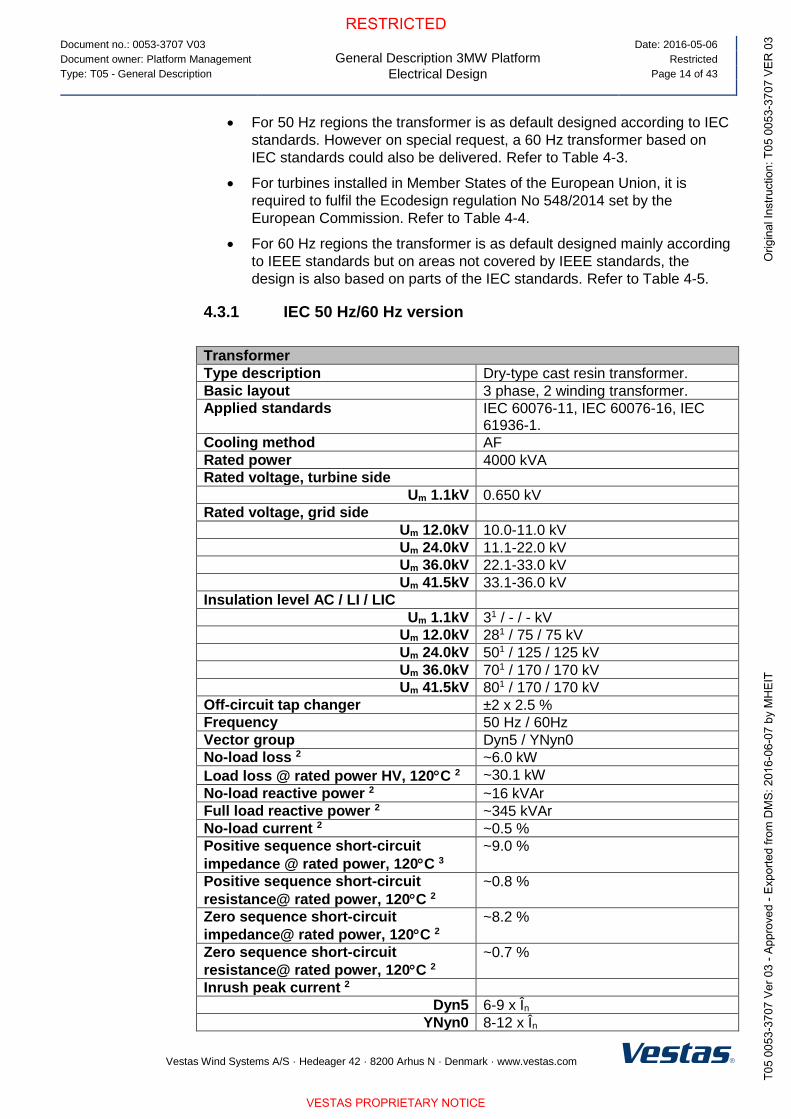
For 50 Hz regions the transformer is as default designed according to IEC
standards. However on special request, a 60 Hz transformer based on
IEC standards could also be delivered. Refer to Table 4-3.
For turbines installed in Member States of the European Union, it is
required to fulfil the Ecodesign regulation No 548/2014 set by the
European Commission. Refer to Table 4-4.
For 60 Hz regions the transformer is as default designed mainly according
to IEEE standards but on areas not covered by IEEE standards, the
design is also based on parts of the IEC standards. Refer to Table 4-5.
4.3.1 IEC 50 Hz/60 Hz version
Transformer
Type description Dry-type cast resin transformer.
Basic layout 3 phase, 2 winding transformer.
Applied standards IEC 60076-11, IEC 60076-16, IEC 61936-1.
Cooling method AF
Rated power 4000 kVA
Rated voltage, turbine side
Um 1.1kV 0.650 kV
Rated voltage, grid side
Um 12.0kV 10.0-11.0 kV
Um 24.0kV 11.1-22.0 kV
Um 36.0kV 22.1-33.0 kV
Um 41.5kV 33.1-36.0 kV
Insulation level AC / LI / LIC
Um 1.1kV 31 / - / - kV
Um 12.0kV 281 / 75 / 75 kV
Um 24.0kV 501 / 125 / 125 kV
Um 36.0kV 701 / 170 / 170 kV
Um 41.5kV 801 / 170 / 170 kV
Off-circuit tap changer ±2 x 2.5 %
Frequency 50 Hz / 60Hz
Vector group Dyn5 / YNyn0
No-load loss 2 ~6.0 kW
Load loss @ rated power HV, 120C 2 ~30.1 kW
No-load reactive power 2 ~16 kVAr
Full load reactive power 2 ~345 kVAr
No-load current 2 ~0.5 %
Positive sequence short-circuit
impedance @ rated power, 120C 3
~9.0 %
Positive sequence short-circuit
resistance@ rated power, 120C 2
~0.8 %
Zero sequence short-circuit
impedance@ rated power, 120C 2
~8.2 %
Zero sequence short-circuit
resistance@ rated power, 120C 2
~0.7 %
Inrush peak current 2
Dyn5 6-9 x În
YNyn0 8-12 x În
Document no.: 0053-3707 V03
General Description 3MW Platform
Electrical Design
Date: 2016-05-06
Document owner: Platform Management Restricted
Type: T05 - General Description Page 15 of 43
Vestas Wind Systems A/S · Hedeager 42 · 8200 Arhus N · Denmark · www.vestas.com
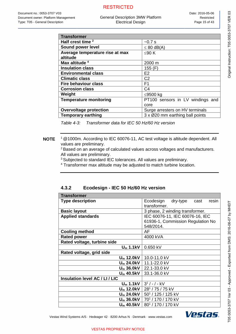
Transformer
Half crest time 2 ~0.7 s
Sound power level 80 dB(A)
Average temperature rise at max altitude
90 K
Max altitude 4 2000 m
Insulation class 155 (F)
Environmental class E2
Climatic class C2
Fire behaviour class F1
Corrosion class C4
Weight 9500 kg
Temperature monitoring PT100 sensors in LV windings and core
Overvoltage protection Surge arresters on HV terminals
Temporary earthing 3 x Ø20 mm earthing ball points
Table 4-3: Transformer data for IEC 50 Hz/60 Hz version
1 @1000m. According to IEC 60076-11, AC test voltage is altitude dependent. All
values are preliminary. 2 Based on an average of calculated values across voltages and manufacturers.
All values are preliminary.
3 Subjected to standard IEC tolerances. All values are preliminary. 4 Transformer max altitude may be adjusted to match turbine location.
4.3.2 Ecodesign - IEC 50 Hz/60 Hz version
Transformer
Type description Ecodesign dry-type cast resin transformer.
Basic layout 3 phase, 2 winding transformer.
Applied standards IEC 60076-11, IEC 60076-16, IEC 61936-1, Commission Regulation No 548/2014.
Cooling method AF
Rated power 4000 kVA
Rated voltage, turbine side
Um 1.1kV 0.650 kV
Rated voltage, grid side
Um 12.0kV 10.0-11.0 kV
Um 24.0kV 11.1-22.0 kV
Um 36.0kV 22.1-33.0 kV
Um 40.5kV 33.1-36.0 kV
Insulation level AC / LI / LIC
Um 1.1kV 31 / - / - kV
Um 12.0kV 281 / 75 / 75 kV
Um 24.0kV 501 / 125 / 125 kV
Um 36.0kV 701 / 170 / 170 kV
Um 40.5kV 801 / 170 / 170 kV
NOTE

Document no.: 0053-3707 V03
General Description 3MW Platform
Electrical Design
Date: 2016-05-06
Document owner: Platform Management Restricted
Type: T05 - General Description Page 16 of 43
Vestas Wind Systems A/S · Hedeager 42 · 8200 Arhus N · Denmark · www.vestas.com
Transformer
Off-circuit tap changer ±2 x 2.5 %
Frequency 50 Hz / 60 Hz
Vector group Dyn5 / YNyn0
Peak Efficiency Index (PEI) 2 Ecodesign requirement
Um 12.0kV > 99.348
Um 24.0kV > 99.348
Um 36.0kV > 99.348
Um 40.5kV > 99.158
No-load loss 2
Um 12.0kV < 5800 W
Um 24.0kV < 5800 W
Um 36.0kV < 5800 W
Um 40.5kV < 6900 W
Load loss @ rated power HV, 120C 2
Um 12.0kV < 29300 W
Um 24.0kV < 29300 W
Um 36.0kV < 29300 W
Um 40.5kV < 37850 W
No-load reactive power 3 ~25 kVAr
Full load reactive power 3 ~370 kVAr
No-load current 3 ~0.5 %
Positive sequence short-circuit
impedance @ rated power, 120C 4
~9.0 %
Positive sequence short-circuit
resistance@ rated power, 120C 3
~0.8 %
Zero sequence short-circuit
impedance@ rated power, 120C 3
~8.2 %
Zero sequence short-circuit
resistance@ rated power, 120C 3
~0.7 %
Inrush peak current 3
Dyn5 6-9 x În
YNyn0 8-12 x În
Half crest time 3 ~ 0.7 s
Sound power level 80 dB(A)
Average temperature rise at max altitude
90 K
Max altitude 5 2000 m
Insulation class 155 (F)
Environmental class E2
Climatic class C2
Fire behaviour class F1
Corrosion class C4
Weight 10000 kg
Temperature monitoring PT100 sensors in LV windings and core
Overvoltage protection Surge arresters on HV terminals
Temporary earthing 3 x Ø20 mm earthing ball points
Table 4-4: Transformer data for Ecodesign IEC 50 Hz/60 Hz version.

Document no.: 0053-3707 V03
General Description 3MW Platform
Electrical Design
Date: 2016-05-06
Document owner: Platform Management Restricted
Type: T05 - General Description Page 17 of 43
Vestas Wind Systems A/S · Hedeager 42 · 8200 Arhus N · Denmark · www.vestas.com
1 @1000m. According to IEC 60076-11, AC test voltage is altitude dependent. All
values are preliminary. 2 For Ecodesign transformers, PEI is the legal requirement and is calculated
according to the Commission Regulation based on rated power, no-load and load
losses. Losses are maximum values and will not simultaneously occur in a
specific design as this will be incompliant with the PEI requirement. All values are
preliminary. 3 Based on an average of calculated values across voltages and manufacturers.
All values are preliminary. 4 Subjected to standard IEC tolerances. All values are preliminary. 5 Transformer max altitude may be adjusted to match turbine location.
4.3.3 IEEE 60Hz version
Transformer
Type description Dry-type cast resin transformer.
Basic layout 3 phase, 2 winding transformer.
Applied standards UL 1562, CSA C22.2 No. 47, IEEE C57.12, IEC 60076-11, IEC 60076-16, IEC 61936-1.
Cooling method AFA
Rated power 4000 kVA
Rated voltage, turbine side
NLL 1.2 kV 0.650 kV
Rated voltage, grid side
NLL 15.0 kV 10.0-15.0 kV
NLL 25.0 kV 15.1-25.0 kV
NLL 34.5 kV 25.1-34.5 kV
Insulation level AC / LI & LIC
NLL 1.2 kV 41 / +10 kV
NLL 15.0 kV 341 / +95 kV
NLL 25.0 kV 501 / +125 kV
NLL 34.5 kV 701 / (+150 & -170) or +170 kV
Off-circuit tap changer ±2 x 2.5 %
Frequency 60 Hz
Vector group Dyn5 / YNyn0
No-load loss 2 ~6.0 kW
Load loss @ rated power HV, 120C 2 ~30.1 kW
No-load reactive power 2 ~16 kVAr
Full load reactive power 2 ~345 kVAr
No-load current 2 ~0.5 %
Positive sequence short-circuit
impedance @ rated power, 120C 3
~9.0 %
Positive sequence short-circuit
resistance @ rated power, 120C 2
~0.7 %
Zero sequence short-circuit
impedance @ rated power, 120C 2
~8.3 %
Zero sequence short-circuit ~0.7 %
NOTE
Document no.: 0053-3707 V03
General Description 3MW Platform
Electrical Design
Date: 2016-05-06
Document owner: Platform Management Restricted
Type: T05 - General Description Page 18 of 43
Vestas Wind Systems A/S · Hedeager 42 · 8200 Arhus N · Denmark · www.vestas.com
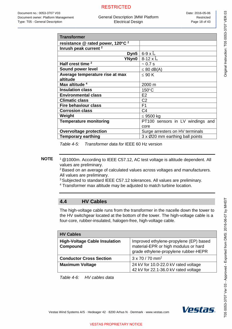
Transformer
resistance @ rated power, 120C 2
Inrush peak current 2
Dyn5 6-9 x În
YNyn0 8-12 x În
Half crest time 2 ~ 0.7 s
Sound power level 80 dB(A)
Average temperature rise at max altitude
90 K
Max altitude 4 2000 m
Insulation class 150C
Environmental class E2
Climatic class C2
Fire behaviour class F1
Corrosion class C4
Weight 9500 kg
Temperature monitoring PT100 sensors in LV windings and core
Overvoltage protection Surge arresters on HV terminals
Temporary earthing 3 x Ø20 mm earthing ball points
Table 4-5: Transformer data for IEEE 60 Hz version
1 @1000m. According to IEEE C57.12, AC test voltage is altitude dependent. All
values are preliminary. 2 Based on an average of calculated values across voltages and manufacturers.
All values are preliminary.
3 Subjected to standard IEEE C57.12 tolerances. All values are preliminary. 4 Transformer max altitude may be adjusted to match turbine location.
4.4 HV Cables
The high-voltage cable runs from the transformer in the nacelle down the tower to
the HV switchgear located at the bottom of the tower. The high-voltage cable is a
four-core, rubber-insulated, halogen-free, high-voltage cable.
HV Cables
High-Voltage Cable Insulation
Compound
Improved ethylene-propylene (EP) based
material-EPR or high modulus or hard
grade ethylene-propylene rubber-HEPR
Conductor Cross Section 3 x 70 / 70 mm2
Maximum Voltage 24 kV for 10.0-22.0 kV rated voltage
42 kV for 22.1-36.0 kV rated voltage
Table 4-6: HV cables data
NOTE

Document no.: 0053-3707 V03
General Description 3MW Platform
Electrical Design
Date: 2016-05-06
Document owner: Platform Management Restricted
Type: T05 - General Description Page 19 of 43
Vestas Wind Systems A/S · Hedeager 42 · 8200 Arhus N · Denmark · www.vestas.com
4.5 HV Switchgear
A gas insulated switchgear is installed in the bottom of the tower as an integrated
part of the turbine. Its controls are integrated with the turbine safety system which
monitors the condition of the switchgear and high voltage safety related devices
in the turbine. This ensures all protection devices are fully operational whenever
high voltage components in the turbine are energised. The earthing switch of the
circuit breaker contains a trapped-key interlock system with its counterpart
installed on the access door to the transformer room in order to avoid
unauthorized access to the transformer room during live condition.
The switchgear is available in three variants with increasing features, see Table
4-7. Beside the increase in features, the switchgear can be configured depending
on the number of grid cables planned to enter the individual turbine. The design
of the switchgear solution is optimized such grid cables can be connected to the
switchgear even before the tower is installed and still maintain its protection
toward weather conditions and internal condensation due to a gas tight packing.
The switchgear is available in an IEC version and in an IEEE version. The IEEE
version is however only available in the highest voltage class. The electrical
parameters of the switchgear are seen in Table 4-8 for the IEC version and in
Table 4-9 for the IEEE version.
HV Switchgear
Variant Basic Streamline Standard
IEC standards
IEEE standards
Vacuum circuit breaker panel
Overcurrent, short-circuit and earth fault
protection
Disconnector / earthing switch in circuit
breaker panel
Voltage Presence Indicator System for
circuit breaker
Voltage Presence Indicator System for grid
cables
Double grid cable connection
Triple grid cable connection
Preconfigured relay settings
Turbine safety system integration
Redundant trip coil circuits
Trip coil supervision
Pendant remote control from outside of
tower
Sequential energization
Reclose blocking function

Document no.: 0053-3707 V03
General Description 3MW Platform
Electrical Design
Date: 2016-05-06
Document owner: Platform Management Restricted
Type: T05 - General Description Page 20 of 43
Vestas Wind Systems A/S · Hedeager 42 · 8200 Arhus N · Denmark · www.vestas.com
HV Switchgear
Variant Basic Streamline Standard
Heating elements
Trapped-key interlock system for circuit
breaker panel
UPS power back-up for protection circuits
Motor operation of circuit breaker
Cable panel for grid cables (configurable)
Switch disconnector panels for grid cables
– max three panels (configurable)
Earthing switch for grid cables
Internal arc classification
Supervision on MCB’s
Motor operation of switch disconnector
SCADA ready
SCADA operation of circuit breaker
SCADA operation of switch disconnector
Table 4-7: HV switchgear variants and features.
4.5.1 IEC 50/60Hz version
HV Switchgear
Type description Gas Insulated Switchgear
Applied standards IEC 62271-103 IEC 62271-1, 62271-100, 62271-102, 62271-200, IEC 60694
Insulation medium SF6
Rated voltage
Ur 24.0kV 10.0-22.0 kV
Ur 36.0kV 22.1-33.0 kV
Ur 40.5kV 33.1-36.0 kV
Rated insulation level AC // LI Common value / across isolation distance
Ur 24.0kV 50 / 60 // 125 / 145 kV
Ur 36.0kV 70 / 80 // 170 / 195 kV
Ur 40.5kV 85 / 90 // 185 / 215 kV
Rated frequency 50 Hz / 60 Hz
Rated normal current 630 A
Rated Short-time withstand current
Ur 24.0kV 20 kA
Ur 36.0kV 25 kA
Ur 40.5kV 25 kA
Rated peak withstand current 50 / 60 Hz
Ur 24.0kV 50 / 52 kA
Ur 36.0kV 62.5 / 65 kA

Document no.: 0053-3707 V03
General Description 3MW Platform
Electrical Design
Date: 2016-05-06
Document owner: Platform Management Restricted
Type: T05 - General Description Page 21 of 43
Vestas Wind Systems A/S · Hedeager 42 · 8200 Arhus N · Denmark · www.vestas.com
HV Switchgear
Ur 40.5kV 62.5 / 65 kA
Rated duration of short-circuit 1 s
Internal arc classification (option)
Ur 24.0kV IAC A FLR 20 kA, 1 s
Ur 36.0kV IAC A FLR 25 kA, 1 s
Ur 40.5kV IAC A FLR 25 kA, 1 s
Connection interface Outside cone plug-in bushings, IEC interface C1.
Loss of service continuity category LSC2
Ingress protection
Gas tank IP 65
Enclosure IP 2X
LV cabinet IP 3X
Corrosion class C3
Table 4-8: HV switchgear data for IEC version.
4.5.2 IEEE 60Hz version
HV Switchgear
Type description Gas Insulated Switchgear
Applied standards IEEE 37.20.3, IEEE C37.20.4, IEC 62271-200, ISO 12944.
Insulation medium SF6
Rated voltage
Ur 38.0kV 22.1-36.0 kV
Rated insulation level AC / LI 70 / 150 kV
Rated frequency 60 Hz
Rated normal current 600 A
Rated Short-time withstand current 25 kA
Rated peak withstand current 65 kA
Rated duration of short-circuit 1 s
Internal arc classification (option) IAC A FLR 25 kA, 1 s
Connection interface grid cables Outside cone plug-in bushings, IEEE 386 interface type deadbreak, 600A.
Ingress protection
Gas tank NEMA 4X / IP 65
Enclosure NEMA 2 / IP 2X
LV cabinet NEMA 2 / IP 3X
Corrosion class C3
Table 4-9: HV switchgear data for IEEE version.
4.6 AUX System
The AUX system is supplied from a separate 650/400/230 V transformer located
in the nacelle inside the converter cabinet. All motors, pumps, fans and heaters
are supplied from this system.
230 V consumers are generally supplied from a 400/230 V transformer located in
the tower base. Internal heating and ventilation of cabinets as well as specific
option 230 V consumers are supplied from the auxiliary transformer in the
converter cabinet.
Document no.: 0053-3707 V03
General Description 3MW Platform
Electrical Design
Date: 2016-05-06
Document owner: Platform Management Restricted
Type: T05 - General Description Page 22 of 43
Vestas Wind Systems A/S · Hedeager 42 · 8200 Arhus N · Denmark · www.vestas.com
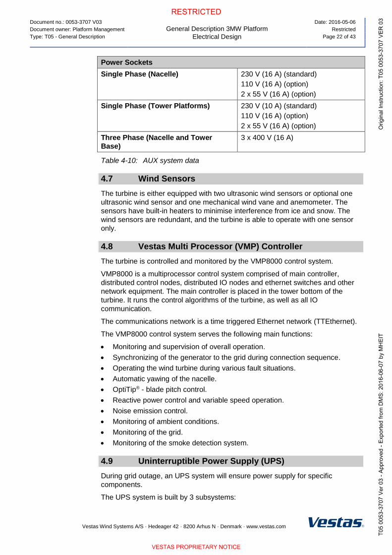
Power Sockets
Single Phase (Nacelle) 230 V (16 A) (standard)
110 V (16 A) (option)
2 x 55 V (16 A) (option)
Single Phase (Tower Platforms) 230 V (10 A) (standard)
110 V (16 A) (option)
2 x 55 V (16 A) (option)
Three Phase (Nacelle and Tower
Base)
3 x 400 V (16 A)
Table 4-10: AUX system data
4.7 Wind Sensors
The turbine is either equipped with two ultrasonic wind sensors or optional one
ultrasonic wind sensor and one mechanical wind vane and anemometer. The
sensors have built-in heaters to minimise interference from ice and snow. The
wind sensors are redundant, and the turbine is able to operate with one sensor
only.
4.8 Vestas Multi Processor (VMP) Controller
The turbine is controlled and monitored by the VMP8000 control system.
VMP8000 is a multiprocessor control system comprised of main controller,
distributed control nodes, distributed IO nodes and ethernet switches and other
network equipment. The main controller is placed in the tower bottom of the
turbine. It runs the control algorithms of the turbine, as well as all IO
communication.
The communications network is a time triggered Ethernet network (TTEthernet).
The VMP8000 control system serves the following main functions:
Monitoring and supervision of overall operation.
Synchronizing of the generator to the grid during connection sequence.
Operating the wind turbine during various fault situations.
Automatic yawing of the nacelle.
OptiTip® - blade pitch control.
Reactive power control and variable speed operation.
Noise emission control.
Monitoring of ambient conditions.
Monitoring of the grid.
Monitoring of the smoke detection system.
4.9 Uninterruptible Power Supply (UPS)
During grid outage, an UPS system will ensure power supply for specific
components.
The UPS system is built by 3 subsystems:

Document no.: 0053-3707 V03
General Description 3MW Platform
Turbine Protection Systems
Date: 2016-05-06
Document owner: Platform Management Restricted
Type: T05 - General Description Page 23 of 43
Vestas Wind Systems A/S · Hedeager 42 · 8200 Arhus N · Denmark · www.vestas.com
1. 230V AC UPS for all power backup to nacelle and hub control systems
2. 24V DC UPS for power backup to tower base control systems and
optional SCADA Power Plant Controller.
3. 230V AC UPS for power backup to internal lights in tower and nacelle.
Internal light in the hub is fed from built-in batteries in the light armature.
UPS
Backup Time Standard Optional
Control System*
(230V AC and 24V DC UPS) 15 min Up to 400 min**
Internal Lights
(230V AC UPS)
30 min 60 min***
Optional SCADA Power
Plant Controller
(24V DC UPS)
N/A 48 hours****
Table 4-11: UPS data
*The control system includes: the turbine controller (VMP8000), HV switchgear
functions, and remote control system.
**Requires upgrade of the 230V UPS for control system with extra batteries.
***Requires upgrade of the 230V UPS for internal light with extra batteries.
****Requires upgrade of the 24V DC UPS with extra batteries.
For alternative backup times, consult Vestas.
5 Turbine Protection Systems
5.1 Braking Concept
The main brake on the turbine is aerodynamic. Stopping the turbine is done by
full feathering the three blades (individually turning each blade). Each blade has
a hydraulic accumulator to supply power for turning the blade.
In addition, there is a mechanical disc brake on the high-speed shaft of the
gearbox with a dedicated hydraulic system. The mechanical brake is only used
as a parking brake and when activating the emergency stop buttons.
NOTE

Document no.: 0053-3707 V03
General Description 3MW Platform
Turbine Protection Systems
Date: 2016-05-06
Document owner: Platform Management Restricted
Type: T05 - General Description Page 24 of 43
Vestas Wind Systems A/S · Hedeager 42 · 8200 Arhus N · Denmark · www.vestas.com
5.2 Short Circuit Protections
Breakers Breaker for Aux.
Power.
(not settled)
Breaker for
Converter Modules
(not settled)
Breaking Capacity, Icu, Ics TBD TBD
Making Capacity, Icm TBD TBD
Table 5-1: Short circuit protection data
5.3 Overspeed Protection
The generator rpm and the main shaft rpm are registered by inductive sensors
and calculated by the wind turbine controller to protect against overspeed and
rotating errors.
The safety-related partition of the VMP8000 control system monitors the rotor
rpm. In case of an overspeed situation, the safety-related partition of the
VMP8000 control system activates the emergency feathered position (full
feathering) of the three blades independently of the non-safety related partition of
VMP8000 control system.
Overspeed Protection
Sensors Type Inductive
Trip Level (variant dependent) 15.3-17.6 rpm / 2000 (generator rpm)
Table 5-3: Overspeed protection data
5.4 Arc Detection
The turbine is equipped with an Arc Detection system including multiple optical
arc detection sensors placed in the HV transformer compartment and the
converter cabinet. The Arc Detection system is connected to the turbine safety
system ensuring immediate opening of the HV switchgear if an arc is detected.
5.5 Smoke Detection
The turbine is equipped with a Smoke Detection system including multiple smoke
detection sensors placed in the nacelle (above the disc brake), in the transformer
compartment, in main electrical cabinets in the nacelle and above the HV
switchgear in the tower base. The Smoke Detection system is connected to the
turbine safety system ensuring immediate opening of the HV switchgear if smoke
is detected.
5.6 Lightning Protection of Blades, Nacelle, Hub and Tower
The Lightning Protection System (LPS) helps protect the wind turbine against the
physical damage caused by lightning strikes. The LPS consists of five main parts:
Lightning receptors. All lightning receptor surfaces on the blades including the
Solid Metal Tips (SMT) are unpainted as standard.

Document no.: 0053-3707 V03
General Description 3MW Platform
Turbine Protection Systems
Date: 2016-05-06
Document owner: Platform Management Restricted
Type: T05 - General Description Page 25 of 43
Vestas Wind Systems A/S · Hedeager 42 · 8200 Arhus N · Denmark · www.vestas.com
Down conducting system (a system to conduct the lightning current down
through the wind turbine to help avoid or minimise damage to the LPS itself or
other parts of the wind turbine).
Protection against overvoltage and overcurrent.
Shielding against magnetic and electrical fields.
Earthing system.
Lightning Protection Design Parameters Protection Level I
Current Peak Value imax [kA] 200
Impulse Charge Qimpulse [C] 100
Long Duration Charge Qlong [C] 200
Total Charge Qtotal [C] 300
Specific Energy W/R [MJ/] 10
Average Steepness di/dt [kA/s] 200
Table 5-4: Lightning protection design parameters
The Lightning Protection System is designed according to IEC standards (see
section 8 Design Codes, p. 28).
5.7 EMC
The turbine and related equipment fulfils the EU Electromagnetic Compatibility
(EMC) legislation:
DIRECTIVE 2014/30/EU OF THE EUROPEAN PARLIAMENT AND OF THE
COUNCIL of 26 February 2014 on the harmonisation of the laws of the
Member States relating to electromagnetic compatibility.
5.8 Earthing
The Vestas Earthing System consists of a number of individual earthing
electrodes interconnected as one joint earthing system.
The Vestas Earthing System includes the TN-system and the Lightning
Protection System for each wind turbine. It works as an earthing system for the
medium voltage distribution system within the wind farm.
The Vestas Earthing System is adapted for the different types of turbine
foundations. A separate set of documents describe the earthing system in detail,
depending on the type of foundation.
In terms of lightning protection of the wind turbine, Vestas has no separate
requirements for a certain minimum resistance to remote earth (measured in
ohms) for this system. The earthing for the lightning protection system is based
on the design and construction of the Vestas Earthing System.
A primary part of the Vestas Earthing System is the main earth bonding bar
placed where all cables enter the wind turbine. All earthing electrodes are
NOTE
Document no.: 0053-3707 V03
General Description 3MW Platform
Safety
Date: 2016-05-06
Document owner: Platform Management Restricted
Type: T05 - General Description Page 26 of 43
Vestas Wind Systems A/S · Hedeager 42 · 8200 Arhus N · Denmark · www.vestas.com
connected to this main earth bonding bar. Additionally, equipotential connections
are made to all cables entering or leaving the wind turbine.
Requirements in the Vestas Earthing System specifications and work
descriptions are minimum requirements from Vestas and IEC. Local and national
requirements, as well as project requirements, may require additional measures.
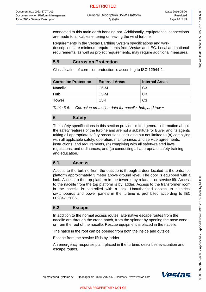
5.9 Corrosion Protection
Classification of corrosion protection is according to ISO 12944-2.
Corrosion Protection External Areas Internal Areas
Nacelle C5-M C3
Hub C5-M C3
Tower C5-I C3
Table 5-5: Corrosion protection data for nacelle, hub, and tower
6 Safety
The safety specifications in this section provide limited general information about
the safety features of the turbine and are not a substitute for Buyer and its agents
taking all appropriate safety precautions, including but not limited to (a) complying
with all applicable safety, operation, maintenance, and service agreements,
instructions, and requirements, (b) complying with all safety-related laws,
regulations, and ordinances, and (c) conducting all appropriate safety training
and education.
6.1 Access
Access to the turbine from the outside is through a door located at the entrance
platform approximately 3 meter above ground level. The door is equipped with a
lock. Access to the top platform in the tower is by a ladder or service lift. Access
to the nacelle from the top platform is by ladder. Access to the transformer room
in the nacelle is controlled with a lock. Unauthorised access to electrical
switchboards and power panels in the turbine is prohibited according to IEC
60204-1 2006.
6.2 Escape
In addition to the normal access routes, alternative escape routes from the
nacelle are through the crane hatch, from the spinner by opening the nose cone,
or from the roof of the nacelle. Rescue equipment is placed in the nacelle.
The hatch in the roof can be opened from both the inside and outside.
Escape from the service lift is by ladder.
An emergency response plan, placed in the turbine, describes evacuation and
escape routes.

Document no.: 0053-3707 V03
General Description 3MW Platform
Safety
Date: 2016-05-06
Document owner: Platform Management Restricted
Type: T05 - General Description Page 27 of 43
Vestas Wind Systems A/S · Hedeager 42 · 8200 Arhus N · Denmark · www.vestas.com
6.3 Rooms/Working Areas
The tower and nacelle are equipped with power sockets for electrical tools for
service and maintenance of the turbine.
6.4 Floors, Platforms, Standing, and Working Places
All floors have anti-slip surfaces.
There is one floor per tower section.
Rest platforms are provided at intervals of 9 metres along the tower ladder
between platforms.
Foot supports are placed in the turbine for maintenance and service purposes.
6.5 Service Lift
The turbine is delivered with a service lift installed as an option.
6.6 Climbing Facilities
A ladder with a fall arrest system (rigid rail) is installed through the tower.
There are anchor points in the tower, nacelle and hub, and on the roof for
attaching fall arrest equipment (full-body harness).
Over the crane hatch there is an anchor point for the emergency descent
equipment.
Anchor points are coloured yellow and are calculated and tested to 22.2 kN.
6.7 Moving Parts, Guards, and Blocking Devices
All moving parts in the nacelle are shielded.
The turbine is equipped with a rotor lock to block the rotor and drive train.
Blocking the pitch of the cylinder can be done with mechanical tools in the hub.
6.8 Lights
The turbine is equipped with lights in the tower, nacelle, transformer room, and
hub.
There is emergency light in case of the loss of electrical power.
6.9 Emergency Stop
There are emergency stop buttons in the nacelle, hub and bottom of the tower.
6.10 Power Disconnection
The turbine is equipped with breakers to allow for disconnection from all power
sources during inspection or maintenance. The switches are marked with signs
and are located in the nacelle and bottom of the tower.

Document no.: 0053-3707 V03
General Description 3MW Platform
Environment
Date: 2016-05-06
Document owner: Platform Management Restricted
Type: T05 - General Description Page 28 of 43
Vestas Wind Systems A/S · Hedeager 42 · 8200 Arhus N · Denmark · www.vestas.com
6.11 Fire Protection/First Aid
A handheld 5-6 kg CO2 fire extinguisher, first aid kit and fire blanket are required
to be located in the nacelle during service and maintenance.
A handheld 5-6 kg CO2 fire extinguisher is required only during service and
maintenance activities, unless a permanently mounted fire extinguisher
located in the nacelle is mandatorily required by authorities.
First aid kits are required only during service and maintenance activities.
Fire blankets are required only during non-electrical hot work activities.
6.12 Warning Signs
Warning signs placed inside or on the turbine must be reviewed before operating
or servicing the turbine.
6.13 Manuals and Warnings
The Vestas Corporate OH&S Manual and manuals for operation, maintenance
and service of the turbine provide additional safety rules and information for
operating, servicing or maintaining the turbine.
7 Environment
7.1 Chemicals
Chemicals used in the turbine are evaluated according to the Vestas Wind
Systems A/S Environmental System certified according to ISO 14001:2004. The
following chemicals are used in the turbine:
Anti-freeze to help prevent the cooling system from freezing.
Gear oil for lubricating the gearbox.
Hydraulic oil to pitch the blades and operate the brake.
Grease to lubricate bearings.
Various cleaning agents and chemicals for maintenance of the turbine.
8 Design Codes
8.1 Design Codes – Structural Design
The turbine design has been developed and tested with regard to, but not limited
to, the following main standards:
Design Codes
Nacelle and Hub IEC 61400-1 Edition 3
EN 50308
Tower IEC 61400-1 Edition 3
Eurocode 3
Blades DNV-OS-J102
IEC 1024-1

Document no.: 0053-3707 V03
General Description 3MW Platform
Colours
Date: 2016-05-06
Document owner: Platform Management Restricted
Type: T05 - General Description Page 29 of 43
Vestas Wind Systems A/S · Hedeager 42 · 8200 Arhus N · Denmark · www.vestas.com
Design Codes
IEC 60721-2-4
IEC 61400 (Part 1, 12 and 23)
IEC WT 01 IEC
DEFU R25
ISO 2813
DS/EN ISO 12944-2
Gearbox ISO 81400-4
Generator IEC 60034
Transformer IEC 60076-11, IEC 60076-16, CENELEC
HD637 S1
Lightning Protection
IEC 62305-1: 2006
IEC 62305-3: 2006
IEC 62305-4: 2006
IEC 61400-24:2010
Rotating Electrical Machines IEC 34
Safety of Machinery,
Safety-related Parts of Control
Systems
IEC 13849-1
Safety of Machinery – Electrical
Equipment of Machines IEC 60204-1
Table 8-1: Design codes
9 Colours
9.1 Nacelle Colour
Colour of Vestas Nacelles
Standard Nacelle Colour RAL 7035 (light grey)
Standard Logo Vestas
Table 9-1: Colour, nacelle
9.2 Tower Colour
Colour of Vestas Tower Section
External: Internal:
Standard Tower Colour RAL 7035 (light grey) RAL 9001 (cream white)
Table 9-2: Colour, tower
Document no.: 0053-3707 V03
General Description 3MW Platform
Operational Envelope and Performance Guidelines
Date: 2016-05-06
Document owner: Platform Management Restricted
Type: T05 - General Description Page 30 of 43
Vestas Wind Systems A/S · Hedeager 42 · 8200 Arhus N · Denmark · www.vestas.com
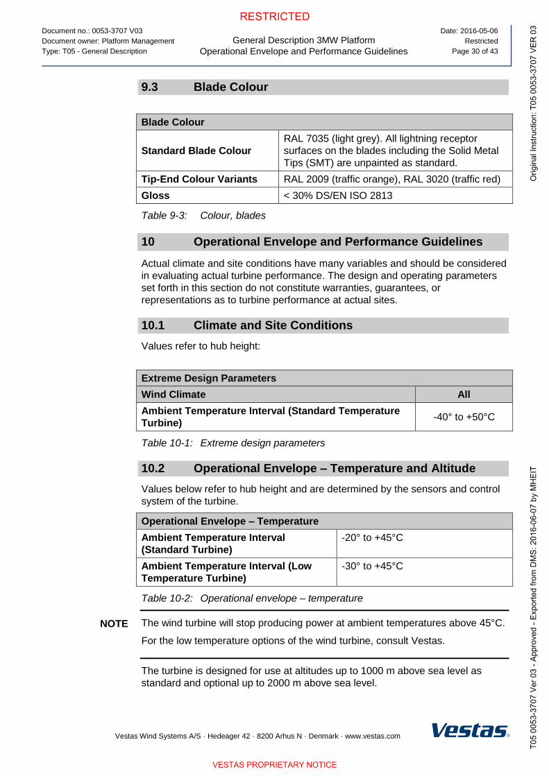
9.3 Blade Colour
Blade Colour
Standard Blade Colour
RAL 7035 (light grey). All lightning receptor
surfaces on the blades including the Solid Metal
Tips (SMT) are unpainted as standard.
Tip-End Colour Variants RAL 2009 (traffic orange), RAL 3020 (traffic red)
Gloss < 30% DS/EN ISO 2813
Table 9-3: Colour, blades
10 Operational Envelope and Performance Guidelines
Actual climate and site conditions have many variables and should be considered
in evaluating actual turbine performance. The design and operating parameters
set forth in this section do not constitute warranties, guarantees, or
representations as to turbine performance at actual sites.
10.1 Climate and Site Conditions
Values refer to hub height:
Extreme Design Parameters
Wind Climate All
Ambient Temperature Interval (Standard Temperature
Turbine) -40° to +50°C
Table 10-1: Extreme design parameters
10.2 Operational Envelope – Temperature and Altitude
Values below refer to hub height and are determined by the sensors and control
system of the turbine.
Operational Envelope – Temperature
Ambient Temperature Interval
(Standard Turbine)
-20° to +45°C
Ambient Temperature Interval (Low
Temperature Turbine)
-30° to +45°C
Table 10-2: Operational envelope – temperature
The wind turbine will stop producing power at ambient temperatures above 45°C.
For the low temperature options of the wind turbine, consult Vestas.
The turbine is designed for use at altitudes up to 1000 m above sea level as
standard and optional up to 2000 m above sea level.
NOTE

Document no.: 0053-3707 V03
General Description 3MW Platform
Operational Envelope and Performance Guidelines
Date: 2016-05-06
Document owner: Platform Management Restricted
Type: T05 - General Description Page 31 of 43
Vestas Wind Systems A/S · Hedeager 42 · 8200 Arhus N · Denmark · www.vestas.com
10.3 Operational Envelope – Temperature and Altitude Derating in 3.45 MW Mode 0
Values below refer to hub height and are determined by the sensors and control
system of the turbine. At ambient temperatures above an altitude-specific
threshold (+30°C for ≤1250 m.a.s.l.), the turbine will maintain derated production
in 3.45 MW Mode 0, within the component capacity as seen in Figure 10-1.
Figure 10-1: Temperature and altitude derated operation for 3.45 MW Mode 0.
10.4 Operational Envelope – Temperature and Altitude Derating in 3.6 MW Power Optimized Mode (PO1)
Derating chart for 3.6 MW Power Optimized Mode (PO1) is shown in Figure 10-2.
Figure 10-2: Temperature and altitude derated operation for 3.6 MW Power
Optimized Mode (PO1).

Document no.: 0053-3707 V03
General Description 3MW Platform
Operational Envelope and Performance Guidelines
Date: 2016-05-06
Document owner: Platform Management Restricted
Type: T05 - General Description Page 32 of 43
Vestas Wind Systems A/S · Hedeager 42 · 8200 Arhus N · Denmark · www.vestas.com
10.5 Operational Envelope – Temperature and Altitude Derating in 3.3 MW Load Optimized Mode (LO1)
Derating chart for 3.3 MW Load Optimized Mode (LO1) is shown in Figure 10-3.
Figure 10-3: Temperature and altitude derated operation for 3.3 MW Load
Optimized Mode (LO1).
10.6 Operational Envelope – Temperature and Altitude Derating in 3.0 MW Load Optimized Mode (LO2)
Derating chart for 3.0 MW Load Optimized Mode (LO2) is shown in Figure 10-4.
Figure 10-4: Temperature and altitude derated operation for 3.0 MW Load
Optimized Mode (LO2).

Document no.: 0053-3707 V03
General Description 3MW Platform
Operational Envelope and Performance Guidelines
Date: 2016-05-06
Document owner: Platform Management Restricted
Type: T05 - General Description Page 33 of 43
Vestas Wind Systems A/S · Hedeager 42 · 8200 Arhus N · Denmark · www.vestas.com
10.7 Operational Envelope – Grid Connection
Operational Envelope – Grid Connection
Nominal Phase Voltage [UNP] 650 V
Nominal Frequency [fN] 50/60 Hz
Maximum Frequency Gradient ±4 Hz/sec.
Maximum Negative Sequence Voltage 3% (connection) 2% (operation)
Minimum Required Short Circuit Ratio
at Turbine HV Connection 5.0
Maximum Short Circuit Current
Contribution
1.05 p.u. (continuous)
1.45 p.u. (peak)
Table 10-3: Operational envelope – grid connection
The generator and the converter will be disconnected if*:
Protection Settings
Voltage Above 110%** of Nominal for 3600 Seconds 715 V
Voltage Above 121% of Nominal for 2 Seconds 787 V
Voltage Above 136% of Nominal for 0.150 Seconds 884 V
Voltage Below 90%** of Nominal for 60 Seconds 585 V
Voltage Below 80% of Nominal for 10 Seconds 520 V
Frequency is Above 106% of Nominal for 0.2 Seconds 53/63.6 Hz
Frequency is Below 94% of Nominal for 0.2 Seconds 47/56.4 Hz
Table 10-4: Generator and converter disconnecting values
* Over the turbine lifetime, grid drop-outs are to occur at an average of no more
than 50 times a year.
** The turbine may be configured for continuous operation @ +/- 13 % voltage.
Reactive power capability is limited for these widened settings (See section 10.8).
All protection settings are preliminary and subject to change.
NOTE

Document no.: 0053-3707 V03
General Description 3MW Platform
Operational Envelope and Performance Guidelines
Date: 2016-05-06
Document owner: Platform Management Restricted
Type: T05 - General Description Page 34 of 43
Vestas Wind Systems A/S · Hedeager 42 · 8200 Arhus N · Denmark · www.vestas.com
10.8 Operational Envelope – Reactive Power Capability in 3.45 MW Mode 0
The 3.45 MW turbine has a reactive power capability in Mode 0 on the low
voltage side of the HV transformer as illustrated in Figure 10-5:
Figure 10-5: Reactive power capability for 3.45 MW Mode 0.
When operating at 3.45 MW nominal power at LV side of the HV transformer, the
reactive power capability on the high voltage side of the HV transformer is
approximately:
cosφ(HV) = 0.95 capacitive @ U(HV) = 0.87 p.u. voltage
cosφ(HV) = 0.94/0.94 capacitive/inductive @ U(HV) = 0.88 p.u. voltage
cosφ(HV) = 0.93/0.91 capacitive/inductive @ U(HV) = 0.90 p.u. voltage
cosφ(HV) = 0.92/0.90 capacitive/inductive @ U(HV) = 1.00 p.u. voltage
cosφ(HV) = 0.95/0.89 capacitive/inductive @ U(HV) = 1.10 p.u. voltage
cosφ(HV) = 0.98/0.89 capacitive/inductive @ U(HV) = 1.13 p.u. voltage
Reactive power is produced by the full-scale converter. Traditional capacitors are,
therefore, not used in the turbine.
The turbine is able to maintain the reactive power capability at low wind with no
active power production.
All reactive power capability values are preliminary and subject to change.
3.45 MW Mode 0 derates above +30°C ambient temperature for ≤1250 m.a.s.l.
according to Figure 10-1.
NOTE

Document no.: 0053-3707 V03
General Description 3MW Platform
Operational Envelope and Performance Guidelines
Date: 2016-05-06
Document owner: Platform Management Restricted
Type: T05 - General Description Page 35 of 43
Vestas Wind Systems A/S · Hedeager 42 · 8200 Arhus N · Denmark · www.vestas.com
10.9 Operational Envelope – Reactive Power Capability in 3.45 MW Reactive Power Optimized Mode (QO1)
An optional, extended reactive power capability is available with 3.45 MW
Reactive Power Optimized Mode (QO1) when ambient temperature is below
+20°C for ≤1250 m.a.s.l. The reactive power capability is as seen in Figure 10-6:
Figure 10-6: Reactive power capability for 3.45 MW Reactive Power Optimized
Mode (QO1).
When operating at 3.45 MW in Reactive Power Optimized Mode (QO1) at LV
side of the HV transformer, the reactive power capability on the high voltage side
of the HV transformer is approximately:
cosφ(HV) = 0.92 capacitive @ U(HV) = 0.87 p.u. voltage
cosφ(HV) = 0.92/0.91 capacitive/inductive @ U(HV) = 0.89 p.u. voltage
cosφ(HV) = 0.91/0.90 capacitive/inductive @ U(HV) = 0.90 p.u. voltage
cosφ(HV) = 0.90/0.88 capacitive/inductive @ U(HV) = 1.00 p.u. voltage
cosφ(HV) = 0.94/0.87 capacitive/inductive @ U(HV) = 1.10 p.u. voltage
cosφ(HV) = 0.97/0.87 capacitive/inductive @ U(HV) = 1.13 p.u. voltage
All reactive power capability values are preliminary and subject to change.
3.45 MW Reactive Power Optimized Mode (PO1) derates reactive power linearly
above +20°C ambient temperature for ≤1250 m.a.s.l. to converge with the
reactive power capability of 3.45 MW Mode 0 in Figure 10-5 at +30°C.
NOTE

Document no.: 0053-3707 V03
General Description 3MW Platform
Operational Envelope and Performance Guidelines
Date: 2016-05-06
Document owner: Platform Management Restricted
Type: T05 - General Description Page 36 of 43
Vestas Wind Systems A/S · Hedeager 42 · 8200 Arhus N · Denmark · www.vestas.com
10.10 Operational Envelope – Reactive Power Capability in 3.6 MW Power Optimized Mode (PO1)
The reactive power capability for the 3.6 MW Power Optimized Mode (PO1) is as
illustrated in Figure 10-7:
Figure 10-7: Reactive power capability for 3.6 MW Power Optimized Mode (PO1).
When operating at 3.6 MW in Power Optimized Mode (PO1) at LV side of the HV
transformer, the reactive power capability on the high voltage side of the HV
transformer is approximately:
cosφ(HV) = 0.96 capacitive @ U(HV) = 0.87 p.u. voltage
cosφ(HV) = 0.95/0.94 capacitive/inductive @ U(HV) = 0.88 p.u. voltage
cosφ(HV) = 0.95/0.92 capacitive/inductive @ U(HV) = 0.90 p.u. voltage
cosφ(HV) = 0.93/0.92 capacitive/inductive @ U(HV) = 1.00 p.u. voltage
cosφ(HV) = 0.96/0.91 capacitive/inductive @ U(HV) = 1.10 p.u. voltage
cosφ(HV) = 0.98/0.90 capacitive/inductive @ U(HV) = 1.13 p.u. voltage
All reactive power capability values are preliminary and subject to change.
3.6 MW Power Optimized Mode (PO1) derates above +20°C ambient
temperature for ≤1250 m.a.s.l. according to Figure 10-2.
3.6 MW Power Optimized Mode (PO1) is mutually exclusive with 3.45 MW
Reactive Power Optimized Mode (QO1) (since Q is traded for P).
NOTE

Document no.: 0053-3707 V03
General Description 3MW Platform
Operational Envelope and Performance Guidelines
Date: 2016-05-06
Document owner: Platform Management Restricted
Type: T05 - General Description Page 37 of 43
Vestas Wind Systems A/S · Hedeager 42 · 8200 Arhus N · Denmark · www.vestas.com
10.11 Operational Envelope – Reactive Power Capability in 3.3 MW Load Optimized Mode (LO1)
The reactive power capability for the 3.3 MW Load Optimized Mode (LO1) is as
illustrated in Figure 10-8:
Figure 10-8: Reactive power capability for 3.3 MW Load Optimized Mode (LO1).
When operating at 3.3 MW in Load Optimized Mode (LO1) at LV side of the HV
transformer, the reactive power capability on the high voltage side of the HV
transformer is approximately:
cosφ(HV) = 0.91 capacitive @ U(HV) = 0.87 p.u. voltage
cosφ(HV) = 0.91/0.91 capacitive/inductive @ U(HV) = 0.89 p.u. voltage
cosφ(HV) = 0.90/0.89 capacitive/inductive @ U(HV) = 0.90 p.u. voltage
cosφ(HV) = 0.90/0.88 capacitive/inductive @ U(HV) = 1.00 p.u. voltage
cosφ(HV) = 0.91/0.89 capacitive/inductive @ U(HV) = 1.10 p.u. voltage
cosφ(HV) = 0.95/0.89 capacitive/inductive @ U(HV) = 1.13 p.u. voltage
All reactive power capability values are preliminary and subject to change.
3.3 MW Load Optimized Mode (LO1) derates above +30°C ambient temperature
for ≤1250 m.a.s.l. according to Figure 10-3.
NOTE
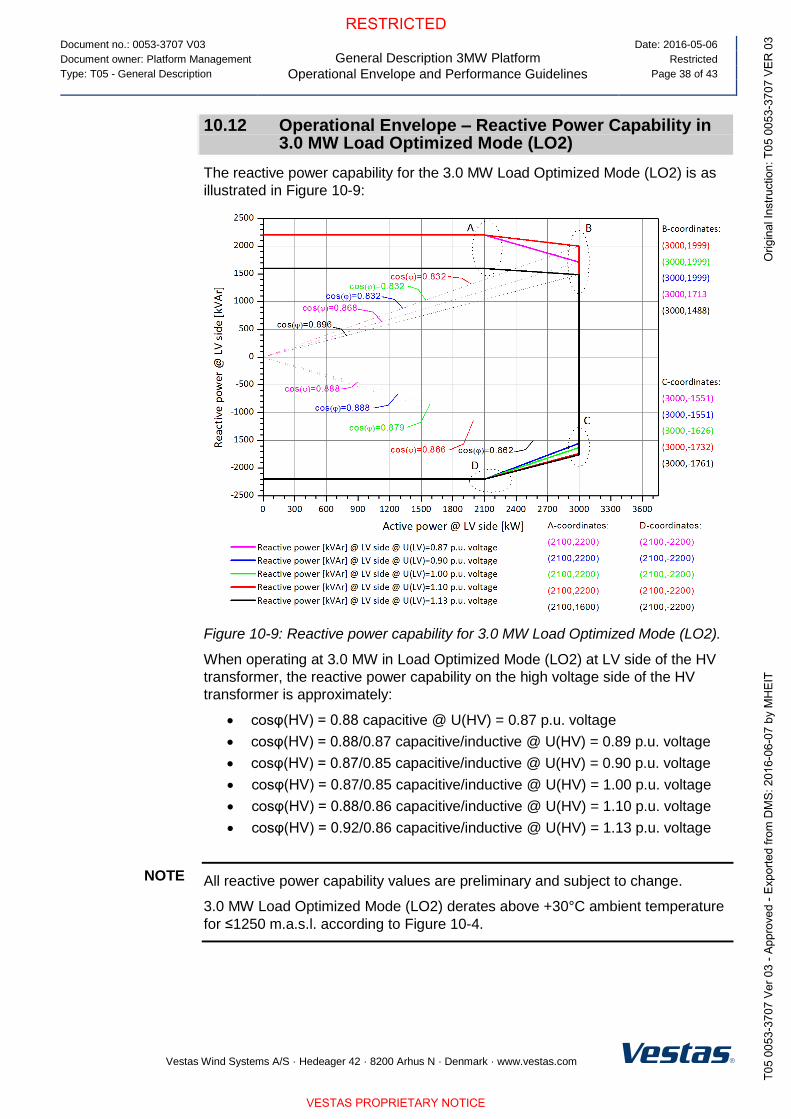
Document no.: 0053-3707 V03
General Description 3MW Platform
Operational Envelope and Performance Guidelines
Date: 2016-05-06
Document owner: Platform Management Restricted
Type: T05 - General Description Page 38 of 43
Vestas Wind Systems A/S · Hedeager 42 · 8200 Arhus N · Denmark · www.vestas.com
10.12 Operational Envelope – Reactive Power Capability in 3.0 MW Load Optimized Mode (LO2)
The reactive power capability for the 3.0 MW Load Optimized Mode (LO2) is as
illustrated in Figure 10-9:
Figure 10-9: Reactive power capability for 3.0 MW Load Optimized Mode (LO2).
When operating at 3.0 MW in Load Optimized Mode (LO2) at LV side of the HV
transformer, the reactive power capability on the high voltage side of the HV
transformer is approximately:
cosφ(HV) = 0.88 capacitive @ U(HV) = 0.87 p.u. voltage
cosφ(HV) = 0.88/0.87 capacitive/inductive @ U(HV) = 0.89 p.u. voltage
cosφ(HV) = 0.87/0.85 capacitive/inductive @ U(HV) = 0.90 p.u. voltage
cosφ(HV) = 0.87/0.85 capacitive/inductive @ U(HV) = 1.00 p.u. voltage
cosφ(HV) = 0.88/0.86 capacitive/inductive @ U(HV) = 1.10 p.u. voltage
cosφ(HV) = 0.92/0.86 capacitive/inductive @ U(HV) = 1.13 p.u. voltage
All reactive power capability values are preliminary and subject to change.
3.0 MW Load Optimized Mode (LO2) derates above +30°C ambient temperature
for ≤1250 m.a.s.l. according to Figure 10-4.
NOTE

Document no.: 0053-3707 V03
General Description 3MW Platform
Operational Envelope and Performance Guidelines
Date: 2016-05-06
Document owner: Platform Management Restricted
Type: T05 - General Description Page 39 of 43
Vestas Wind Systems A/S · Hedeager 42 · 8200 Arhus N · Denmark · www.vestas.com
10.13 Performance – Fault Ride Through
The turbine is equipped with a full-scale converter to gain better control of the
wind turbine during grid faults. The turbine control system continues to run during
grid faults.
The turbine is designed to stay connected during grid disturbances within the
voltage tolerance curve as illustrated:
Voltage FRT-profile (WTG)
0,00; 1,10
0,00; 0,90
10,00; 0,80
10,00; 0,90
2,60; 0,80
0,45; 0,00
0,00; 0,00
0,0
0,1
0,2
0,3
0,4
0,5
0,6
0,7
0,8
0,9
1,0
1,1
1,2
-0,5 0,0 0,5 1,0 1,5 2,0 2,5 3,0 3,5 4,0 4,5 5,0 5,5 6,0 6,5 7,0 7,5 8,0 8,5 9,0 9,5 10,0 10,5 11,0
Time (s)
U (
pu
)
Figure 10-10: Low voltage tolerance curve for symmetrical and asymmetrical
faults, where U represents voltage as measured on the grid.
For grid disturbances outside the tolerance curve in Figure 10-10, the turbine will
be disconnected from the grid.
All fault ride through capability values are preliminary and subject to change.
Power Recovery Time
Power Recovery to 90% of Pre-Fault Level Maximum 0.1 seconds
Table 10-5: Power recovery time
10.14 Performance – Reactive Current Contribution
The reactive current contribution depends on whether the fault applied to the
turbine is symmetrical or asymmetrical.
All reactive current contribution values are preliminary and subject to change.
10.14.1 Symmetrical Reactive Current Contribution
During symmetrical voltage dips, the wind farm will inject reactive current to
support the grid voltage. The reactive current injected is a function of the
measured grid voltage.
NOTE
NOTE

Document no.: 0053-3707 V03
General Description 3MW Platform
Operational Envelope and Performance Guidelines
Date: 2016-05-06
Document owner: Platform Management Restricted
Type: T05 - General Description Page 40 of 43
Vestas Wind Systems A/S · Hedeager 42 · 8200 Arhus N · Denmark · www.vestas.com
The default value gives a reactive current part of 1 p.u. of the rated active current
at the high voltage side of the HV transformer. Figure 10-11, indicates the
reactive current contribution as a function of the voltage. The reactive current
contribution is independent from the actual wind conditions and pre-fault power
level. As seen in Figure 10-11, the default current injection slope is 2% reactive
current increase per 1% voltage decrease. The slope can be parameterized
between 0 and 10 to adapt to site specific requirements.
Figure 10-11: Reactive current injection
10.14.2 Asymmetrical Reactive Current Contribution
The injected current is based on the measured positive sequence voltage and the
used K-factor. During asymmetrical voltage dips, the reactive current injection is
limited to approximate 0.4 p.u. to limit the potential voltage increase on the
healthy phases.
10.15 Performance – Multiple Voltage Dips
The turbine is designed to handle re-closure events and multiple voltage dips
within a short period of time due to the fact that voltage dips are not evenly
distributed during the year. For example, the turbine is designed to handle 10
voltage dips of duration of 200 ms, down to 20% voltage, within 30 minutes.
10.16 Performance – Active and Reactive Power Control
The turbine is designed for control of active and reactive power via the
VestasOnline® SCADA system.
Maximum Ramp Rates for External Control
Active Power 0.1 p.u./sec for max. power level change of 0.3 p.u.
0.3 p.u./sec for max. power level change of 0.1 p.u.
Reactive Power 20 p.u./sec
Table 10-6: Active/reactive power ramp rates (values are preliminary)

Document no.: 0053-3707 V03
General Description 3MW Platform
Operational Envelope and Performance Guidelines
Date: 2016-05-06
Document owner: Platform Management Restricted
Type: T05 - General Description Page 41 of 43
Vestas Wind Systems A/S · Hedeager 42 · 8200 Arhus N · Denmark · www.vestas.com
To support grid stability the turbine is capable to stay connected to the grid at
active power references down to 10 % of nominal power for the turbine. For
active power references below 10 % the turbine may disconnect from the grid.
10.17 Performance – Voltage Control
The turbine is designed for integration with VestasOnline® voltage control by
utilising the turbine reactive power capability.
10.18 Performance – Frequency Control
The turbine can be configured to perform frequency control by decreasing the output power as a linear function of the grid frequency (over frequency). Dead band and slope for the frequency control function are configurable.
10.19 Distortion – Immunity
The turbine is able to connect with a pre-connection (background) voltage distortion level at the grid interface of 8% and operate with a post-connection voltage distortion level of 8%.
10.20 Main Contributors to Own Consumption
The consumption of electrical power by the wind turbine is defined as the power
used by the wind turbine when it is not providing energy to the grid. This is
defined in the control system as Production Generator 0 (zero).
The components in Table 10-7 have the largest influence on the own
consumption of the wind turbine (the average own consumption depends on the
actual conditions, the climate, the wind turbine output, the cut-off hours, etc.).
The VMP8000 control system has a hibernate mode that reduces own
consumption when possible. Similarly, cooling pumps may be turned off when the
turbine idles.
Main contributors to Own Consumption
Hydraulic Motor 2 x 15 kW (master/slave)
Yaw Motors Maximum 18 kW in total
Water Heating 10 kW
Water Pumps 2.2 + 4.0 kW
Oil Heating 7.9 kW
Oil Pump for Gearbox Lubrication 10 kW
Controller Including Heating
Elements for the Hydraulics and all
Controllers
Approximately 3 kW
HV Transformer No-load Loss See section 4.3 HV Transformer, p. 13
Table 10-7: Main contributors to own consumption data (values are preliminary).

Document no.: 0053-3707 V03
General Description 3MW Platform
Drawings
Date: 2016-05-06
Document owner: Platform Management Restricted
Type: T05 - General Description Page 42 of 43
Vestas Wind Systems A/S · Hedeager 42 · 8200 Arhus N · Denmark · www.vestas.com
11 Drawings
11.1 Structural Design – Illustration of Outer Dimensions
Figure 11-1: Illustration of outer dimensions – structure
1 Hub heights: See Performance
Specification
2 Rotor diameter: 105-136 m
11.2 Structural Design – Side View Drawing
Figure 11-2: Side-view drawing

Document no.: 0053-3707 V03
General Description 3MW Platform
General Reservations, Notes and Disclaimers
Date: 2016-05-06
Document owner: Platform Management Restricted
Type: T05 - General Description Page 43 of 43
Vestas Wind Systems A/S · Hedeager 42 · 8200 Arhus N · Denmark · www.vestas.com
12 General Reservations, Notes and Disclaimers
© 2016 Vestas Wind Systems A/S. This document is created by Vestas Wind
Systems A/S and/or its affiliates and contains copyrighted material,
trademarks, and other proprietary information. All rights reserved. No part of
the document may be reproduced or copied in any form or by any means –
such as graphic, electronic, or mechanical, including photocopying, taping, or
information storage and retrieval systems – without the prior written
permission of Vestas Wind Systems A/S. The use of this document is
prohibited unless specifically permitted by Vestas Wind Systems A/S.
Trademarks, copyright or other notices may not be altered or removed from
the document.
The general descriptions in this document apply to the current version of the
3MW Platform wind turbines. Updated versions of the 3MW Platform wind
turbines, which may be manufactured in the future, may differ from this
general description. In the event that Vestas supplies an updated version of a
specific 3MW Platform wind turbine, Vestas will provide an updated general
description applicable to the updated version.
Vestas recommends that the grid be as close to nominal as possible with
limited variation in frequency and voltage.
A certain time allowance for turbine warm-up must be expected following grid
dropout and/or periods of very low ambient temperature.
All listed start/stop parameters (e. g. wind speeds and temperatures) are
equipped with hysteresis control. This can, in certain borderline situations,
result in turbine stops even though the ambient conditions are within the listed
operation parameters.
The earthing system must comply with the minimum requirements from
Vestas, and be in accordance with local and national requirements and codes
of standards.
This document, General Description, is not an offer for sale, and does not
contain any guarantee, warranty and/or verification of the power curve and
noise (including, without limitation, the power curve and noise verification
method). Any guarantee, warranty and/or verification of the power curve and
noise (including, without limitation, the power curve and noise verification
method) must be agreed to separately in writing.

Document no.: 0001-2433 V02
Weight, Dimensions and Centre of Gravity of Nacelle
Date: 2010-11-23
Issued by: Technology R&D Class: 1
Type: T09 - Manual Page 1 of 8
Vestas Wind Systems A/S · Alsvej 21 · 8940 Randers SV · Denmark · www.vestas.com
QM
S 0
00
85
V0
0
Weight, Dimensions and Centre of Gravity of Nacelle This document applies to the turbine types mentioned in section 1 Purpose, p. 2.
Table of Contents
1 Purpose...................................................................................................................................... 2 2 Reference Documents.............................................................................................................. 2 3 Abbreviations and Technical Terms ...................................................................................... 2 4 Technical Data .......................................................................................................................... 3 4.1 Nacelle with Bottom Plate and Rear Legs ................................................................................. 3 4.2 Nacelle with Bottom Plate and Front Adapter ............................................................................ 5 4.3 Nacelle with Bottom Plate and Top Adapters ............................................................................ 7
VESTAS PROPRIETARY NOTICE: This document contains valuable confidential information of Vestas Wind Systems A/S. It is protected by copyright law as an unpublished work. Vestas reserves all patent, copyright, trade secret, and other proprietary rights to it. The information in this document may not be used, reproduced, or disclosed except if and to the extent rights are expressly granted by Vestas in writing and subject to applicable conditions. Vestas disclaims all warranties except as expressly granted by written agreement and is not responsible for unauthorized uses, for which it may pursue legal remedies against responsible parties.

Document no.: 0001-2433 V02
Weight, Dimensions and Centre of Gravity of Nacelle
Purpose
Date: 2010-11-23
Issued by: Technology R&D Class: 1
Type: T09 - Manual Page 2 of 8
Vestas Wind Systems A/S · Alsvej 21 · 8940 Randers SV · Denmark · w w w .vestas.com
1 Purpose
The purpose of this document is to describe the weight, dimensions and centre of
gravity of the nacelle in all configurations.
60 Hz turbines for the North American market will be transported without the door because of the width. See tables below according to configuration.
The nacelles described in this document are used for the turbines stated in Table 1-1, p. 2.
Turbine type
V90-3.0 MW
V100-2.6 MW
Table 1-1: Turbine types.
During transportation, this document must be used together with the transport
manual for the specific turbine type and Mk version.
During installation, this document must be used together with the installation manual for the specific turbine type and Mk version.
2 Reference Documents
Document no. Title
Transport manual for the specific turbine type and Mk version.
Installation manual for the specific turbine type and Mk version.
Table 2-1: Reference documents.
3 Abbreviations and Technical Terms
Abbreviation Spelled-out form / explanation
CoG Centre of Gravity
H Height
L Length
Lw Width
Lcg Distance to the centre of gravity
W Weight
Table 3-1: Abbreviations.
NOTE

Document no.: 0001-2433 V02
Weight, Dimensions and Centre of Gravity of Nacelle
Technical Data
Date: 2010-11-23
Issued by: Technology R&D Class: 1
Type: T09 - Manual Page 3 of 8
Vestas Wind Systems A/S · Alsvej 21 · 8940 Randers SV · Denmark · w w w .vestas.com
4 Technical Data
4.1 Nacelle with Bottom Plate and Rear Legs
Nacelle with bottom plate and rear legs
L
[mm]
Lw 50 Hz [mm]
Lw 60 Hz [mm]
CoG
[mm]
Lcg
[mm]
H
[mm]
W
[kg]
9634 3803 3743 1760 3190 4199 73000
Table 4-1: Weight, dimensions and CoG of nacelle.
Figure 4-1: Length of nacelle transport.

Document no.: 0001-2433 V02
Weight, Dimensions and Centre of Gravity of Nacelle
Technical Data
Date: 2010-11-23
Issued by: Technology R&D Class: 1
Type: T09 - Manual Page 4 of 8
Vestas Wind Systems A/S · Alsvej 21 · 8940 Randers SV · Denmark · w w w .vestas.com
Figure 4-2: Width of nacelle transport. Figure 4-3: Height and centre of gravity
of nacelle transport.
CoG is measured from the left side when looking at the nacelle from the front.
NOTE

Document no.: 0001-2433 V02
Weight, Dimensions and Centre of Gravity of Nacelle
Technical Data
Date: 2010-11-23
Issued by: Technology R&D Class: 1
Type: T09 - Manual Page 5 of 8
Vestas Wind Systems A/S · Alsvej 21 · 8940 Randers SV · Denmark · w w w .vestas.com
4.2 Nacelle with Bottom Plate and Front Adapter
Nacelle with bottom plate and front adapters
L
[mm]
Lw 50 Hz [mm]
Lw 60 Hz [mm]
CoG
[mm]
Lcg
[mm]
H
[mm]
W
[kg]
10074 3803 3743 1760 3190 4199 74500
Table 4-2: Weight, dimensions and CoG of nacelle.
Figure 4-4: Length of nacelle transport.

Document no.: 0001-2433 V02
Weight, Dimensions and Centre of Gravity of Nacelle
Technical Data
Date: 2010-11-23
Issued by: Technology R&D Class: 1
Type: T09 - Manual Page 6 of 8
Vestas Wind Systems A/S · Alsvej 21 · 8940 Randers SV · Denmark · w w w .vestas.com
Figure 4-5: Width of nacelle transport. Figure 4-6: Height and centre of gravity
of nacelle transport.
CoG is measured from the left side when looking at the nacelle from the front.
NOTE

Document no.: 0001-2433 V02
Weight, Dimensions and Centre of Gravity of Nacelle
Technical Data
Date: 2010-11-23
Issued by: Technology R&D Class: 1
Type: T09 - Manual Page 7 of 8
Vestas Wind Systems A/S · Alsvej 21 · 8940 Randers SV · Denmark · w w w .vestas.com
4.3 Nacelle with Bottom Plate and Top Adapters
Nacelle with bottom plate and front and rear top adapters
L
[mm]
Lw 50 Hz [mm]
Lw 60 Hz [mm]
CoG
[mm]
Lcg
[mm]
H
[mm]
W
[kg]
10700 3803 3743 1760 3190 4199 77500
Table 4-3: Weight, dimensions and CoG of nacelle.
Figure 4-7: Nacelle with bottom plate, front and rear top adapters mounted.

Document no.: 0001-2433 V02
Weight, Dimensions and Centre of Gravity of Nacelle
Technical Data
Date: 2010-11-23
Issued by: Technology R&D Class: 1
Type: T09 - Manual Page 8 of 8
Vestas Wind Systems A/S · Alsvej 21 · 8940 Randers SV · Denmark · w w w .vestas.com
Figure 4-8: Width of nacelle transport. Figure 4-9: Height and centre of gravity
of nacelle transport.

Copyright © - Vestas Wind Systems A/S, Hedeager 42, DK-8200 Aarhus N, Denmark, www.vestas.com
QM
S 0
0091 V
ER
00
T05
DOCUMENT:
0058-2095 VER 00 DESCRIPTION:
3MW full range sound curves RESTRICTED
3MW full range sound curves V105 – 3.45/3.6MW
V112 – 3.45/3.6MW
V117 – 3.45/3.6MW
V126 – 3.45MW Low Torque
V126 – 3.45/3.6MW High Torque
V136 – 3.45MW
VESTAS PROPRIETARY NOTICE: This document contains valuable confidential information of Vestas Wind Systems A/S. It is protected by copyright law as an unpublished work. Vestas reserves all patent, copyright, trade secret, and other proprietary rights to it. The information in this document may not be used, reproduced, or disclosed except if and to the extent rights are expressly granted by Vestas in writing and subject to applicable conditions. Vestas disclaims all warranties except as expressly granted by written agreement and is not responsible for unauthorized uses, for which it may pursue legal remedies against responsible parties.

T05
DOCUMENT:
0058-2095 VER 00
DESCRIPTION:
3MW full range sound curves RESTRICTED
PAGE
2/11
Copyright © - Vestas Wind Systems A/S, Hedeager 42, DK-8200 Aarhus N, Denmark, www.vestas.com
QM
S 0
0091 V
ER
00
Table of Contents
CHAPTER: DESCRIPTION: PAGE:
1. Introduction 3 2. Conditions for sound curves 3 3. Sound power level at hub height (Mode 0) 4 4. Sound power level at hub height (Mode 0-0S) 5 5. Sound power level at hub height (Sound Optimized SO1) 6 6. Sound power level at hub height (Sound Optimized SO2) 7 7. Sound power level at hub height (Sound Optimized SO3) 8 8. Sound power level at hub height (Sound Optimized SO4) 9 9. Sound power level at hub height (Sound Optimized SO5) 10 10. Additional remarks 11

T05
DOCUMENT:
0058-2095 VER 00
DESCRIPTION:
3MW full range sound curves RESTRICTED
PAGE
3/11
Copyright © - Vestas Wind Systems A/S, Hedeager 42, DK-8200 Aarhus N, Denmark, www.vestas.com
QM
S 0
0091 V
ER
00
1. Introduction
This document contains full range sound curves from cut-in to cut-out wind speed, as a function of wind
speed for the following 3MW turbine configurations:
V105 – 3.45/3.6MW
V112 – 3.45/3.6MW
V117 – 3.45/3.6MW
V126 – 3.45MW LTq (Low Torque)
V126 – 3.45/3.6MW HTq (High Torque)
V136 – 3.45MW
The sound power levels are continuously varying as a function of wind speed and are not maintained at
maximum sound power level after this is reached.
2. Conditions for sound curves
The following conditions apply to the sound power level values listed in the tables below:
Measurement standard IEC 61400-11 ed. 3
Maximum turbulence at 10 metre height: 16%
Inflow angle (vertical): 0 ±2°
Air density: 1.225 kg/m3
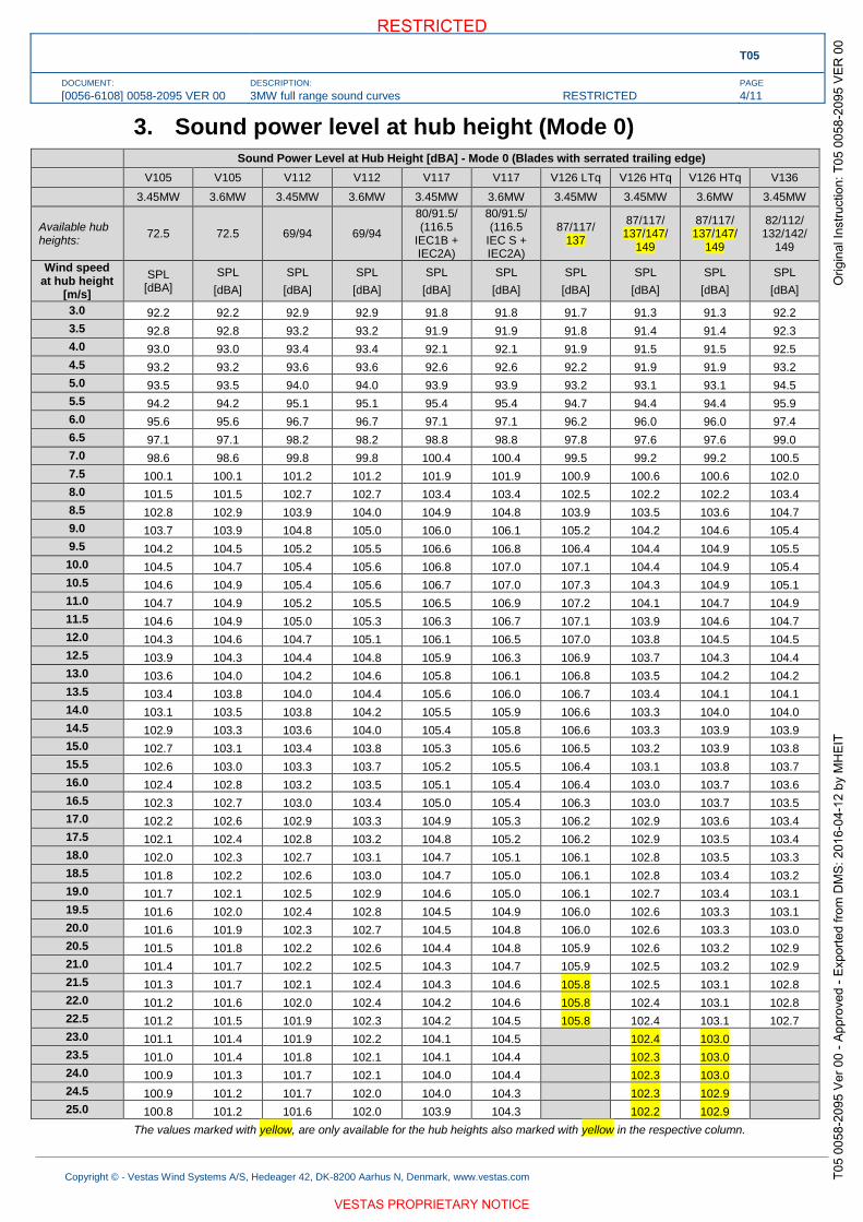
T05
DOCUMENT:
[0056-6108] 0058-2095 VER 00
DESCRIPTION:
3MW full range sound curves RESTRICTED
PAGE
4/11
Copyright © - Vestas Wind Systems A/S, Hedeager 42, DK-8200 Aarhus N, Denmark, www.vestas.com
3. Sound power level at hub height (Mode 0)
Sound Power Level at Hub Height [dBA] - Mode 0 (Blades with serrated trailing edge)
V105 V105 V112 V112 V117 V117 V126 LTq V126 HTq V126 HTq V136
3.45MW 3.6MW 3.45MW 3.6MW 3.45MW 3.6MW 3.45MW 3.45MW 3.6MW 3.45MW
Available hub heights:
72.5 72.5 69/94 69/94
80/91.5/ (116.5
IEC1B + IEC2A)
80/91.5/ (116.5
IEC S + IEC2A)
87/117/ 137
87/117/ 137/147/
149
87/117/ 137/147/
149
82/112/ 132/142/
149
Wind speed at hub height
[m/s]
SPL [dBA]
SPL
[dBA]
SPL
[dBA]
SPL
[dBA]
SPL
[dBA]
SPL
[dBA]
SPL
[dBA]
SPL
[dBA]
SPL
[dBA]
SPL
[dBA]
3.0 92.2 92.2 92.9 92.9 91.8 91.8 91.7 91.3 91.3 92.2
3.5 92.8 92.8 93.2 93.2 91.9 91.9 91.8 91.4 91.4 92.3
4.0 93.0 93.0 93.4 93.4 92.1 92.1 91.9 91.5 91.5 92.5
4.5 93.2 93.2 93.6 93.6 92.6 92.6 92.2 91.9 91.9 93.2
5.0 93.5 93.5 94.0 94.0 93.9 93.9 93.2 93.1 93.1 94.5
5.5 94.2 94.2 95.1 95.1 95.4 95.4 94.7 94.4 94.4 95.9
6.0 95.6 95.6 96.7 96.7 97.1 97.1 96.2 96.0 96.0 97.4
6.5 97.1 97.1 98.2 98.2 98.8 98.8 97.8 97.6 97.6 99.0
7.0 98.6 98.6 99.8 99.8 100.4 100.4 99.5 99.2 99.2 100.5
7.5 100.1 100.1 101.2 101.2 101.9 101.9 100.9 100.6 100.6 102.0
8.0 101.5 101.5 102.7 102.7 103.4 103.4 102.5 102.2 102.2 103.4
8.5 102.8 102.9 103.9 104.0 104.9 104.8 103.9 103.5 103.6 104.7
9.0 103.7 103.9 104.8 105.0 106.0 106.1 105.2 104.2 104.6 105.4
9.5 104.2 104.5 105.2 105.5 106.6 106.8 106.4 104.4 104.9 105.5
10.0 104.5 104.7 105.4 105.6 106.8 107.0 107.1 104.4 104.9 105.4
10.5 104.6 104.9 105.4 105.6 106.7 107.0 107.3 104.3 104.9 105.1
11.0 104.7 104.9 105.2 105.5 106.5 106.9 107.2 104.1 104.7 104.9
11.5 104.6 104.9 105.0 105.3 106.3 106.7 107.1 103.9 104.6 104.7
12.0 104.3 104.6 104.7 105.1 106.1 106.5 107.0 103.8 104.5 104.5
12.5 103.9 104.3 104.4 104.8 105.9 106.3 106.9 103.7 104.3 104.4
13.0 103.6 104.0 104.2 104.6 105.8 106.1 106.8 103.5 104.2 104.2
13.5 103.4 103.8 104.0 104.4 105.6 106.0 106.7 103.4 104.1 104.1
14.0 103.1 103.5 103.8 104.2 105.5 105.9 106.6 103.3 104.0 104.0
14.5 102.9 103.3 103.6 104.0 105.4 105.8 106.6 103.3 103.9 103.9
15.0 102.7 103.1 103.4 103.8 105.3 105.6 106.5 103.2 103.9 103.8
15.5 102.6 103.0 103.3 103.7 105.2 105.5 106.4 103.1 103.8 103.7
16.0 102.4 102.8 103.2 103.5 105.1 105.4 106.4 103.0 103.7 103.6
16.5 102.3 102.7 103.0 103.4 105.0 105.4 106.3 103.0 103.7 103.5
17.0 102.2 102.6 102.9 103.3 104.9 105.3 106.2 102.9 103.6 103.4
17.5 102.1 102.4 102.8 103.2 104.8 105.2 106.2 102.9 103.5 103.4
18.0 102.0 102.3 102.7 103.1 104.7 105.1 106.1 102.8 103.5 103.3
18.5 101.8 102.2 102.6 103.0 104.7 105.0 106.1 102.8 103.4 103.2
19.0 101.7 102.1 102.5 102.9 104.6 105.0 106.1 102.7 103.4 103.1
19.5 101.6 102.0 102.4 102.8 104.5 104.9 106.0 102.6 103.3 103.1
20.0 101.6 101.9 102.3 102.7 104.5 104.8 106.0 102.6 103.3 103.0
20.5 101.5 101.8 102.2 102.6 104.4 104.8 105.9 102.6 103.2 102.9
21.0 101.4 101.7 102.2 102.5 104.3 104.7 105.9 102.5 103.2 102.9
21.5 101.3 101.7 102.1 102.4 104.3 104.6 105.8 102.5 103.1 102.8
22.0 101.2 101.6 102.0 102.4 104.2 104.6 105.8 102.4 103.1 102.8
22.5 101.2 101.5 101.9 102.3 104.2 104.5 105.8 102.4 103.1 102.7
23.0 101.1 101.4 101.9 102.2 104.1 104.5 102.4 103.0
23.5 101.0 101.4 101.8 102.1 104.1 104.4 102.3 103.0
24.0 100.9 101.3 101.7 102.1 104.0 104.4 102.3 103.0
24.5 100.9 101.2 101.7 102.0 104.0 104.3 102.3 102.9
25.0 100.8 101.2 101.6 102.0 103.9 104.3 102.2 102.9
The values marked with yellow, are only available for the hub heights also marked with yellow in the respective column.

T05
DOCUMENT:
[0056-6108] 0058-2095 VER 00
DESCRIPTION:
3MW full range sound curves RESTRICTED
PAGE
5/11
Copyright © - Vestas Wind Systems A/S, Hedeager 42, DK-8200 Aarhus N, Denmark, www.vestas.com
4. Sound power level at hub height (Mode 0-0S)
Sound Power Level at Hub Height [dBA] - Mode 0-0S (Blades without serrated trailing edge)
V105 V105 V112 V112 V117 V117 V126 LTq V126 HTq V126 HTq V136
3.45MW 3.6MW 3.45MW 3.6MW 3.45MW 3.6MW 3.45MW 3.45MW 3.6MW 3.45MW
Available hub heights:
72.5 72.5 69/94 69/94
80/91.5/ (116.5
IEC1B + IEC2A)
80/91.5/ (116.5
IEC S + IEC2A)
87/117/ 137
87/117/ 137/147/
149
87/117/ 137/147/
149
82/112/ 132/142/
149
Wind speed at hub height
[m/s]
SPL [dBA]
SPL
[dBA]
SPL
[dBA]
SPL
[dBA]
SPL
[dBA]
SPL
[dBA]
SPL
[dBA]
SPL
[dBA]
SPL
[dBA]
SPL
[dBA]
3.0 92.4 92.4 93.3 93.3 93.3 93.3 92.5 92.1 92.1 93.0
3.5 93.1 93.1 93.6 93.6 93.5 93.5 92.5 92.2 92.2 93.2
4.0 93.3 93.3 93.9 93.9 93.7 93.7 92.6 92.3 92.3 93.6
4.5 93.6 93.6 94.2 94.2 94.4 94.4 92.9 92.9 92.9 94.7
5.0 93.9 93.9 94.7 94.7 96.0 96.0 94.3 94.4 94.4 96.3
5.5 94.8 94.8 96.0 96.0 97.8 97.8 96.0 96.2 96.2 98.0
6.0 96.2 96.2 97.6 97.6 99.6 99.6 97.8 98.0 98.0 99.8
6.5 97.8 97.8 99.3 99.3 101.3 101.3 99.6 99.9 99.9 101.5
7.0 99.4 99.4 100.9 100.9 103.0 103.1 101.4 101.6 101.6 103.1
7.5 100.9 100.9 102.4 102.4 104.6 104.6 103.0 103.3 103.3 104.6
8.0 102.4 102.4 103.8 103.8 106.1 106.1 104.7 105.0 105.0 106.1
8.5 103.7 103.7 105.1 105.1 107.5 107.5 106.3 106.4 106.5 107.4
9.0 104.6 104.8 106.0 106.1 108.6 108.6 107.7 107.1 107.6 108.1
9.5 105.2 105.4 106.5 106.7 109.2 109.4 108.9 107.4 108.0 108.2
10.0 105.5 105.8 106.7 106.9 109.3 109.6 109.8 107.3 108.0 107.9
10.5 105.8 106.0 106.7 106.9 109.3 109.5 110.1 107.3 107.9 107.6
11.0 105.8 106.0 106.5 106.7 109.1 109.4 110.0 107.2 107.9 107.3
11.5 105.7 105.9 106.2 106.5 108.9 109.3 109.9 107.1 107.8 107.1
12.0 105.3 105.6 105.8 106.2 108.7 109.1 109.9 107.0 107.7 106.8
12.5 104.8 105.3 105.4 105.8 108.6 108.9 109.8 106.9 107.6 106.6
13.0 104.4 104.8 105.1 105.5 108.4 108.8 109.7 106.8 107.5 106.4
13.5 104.0 104.5 104.8 105.2 108.3 108.7 109.7 106.8 107.5 106.3
14.0 103.7 104.2 104.5 105.0 108.2 108.6 109.6 106.7 107.4 106.1
14.5 103.5 103.9 104.3 104.7 108.1 108.4 109.6 106.6 107.4 106.0
15.0 103.2 103.6 104.1 104.5 108.0 108.3 109.6 106.6 107.3 105.8
15.5 103.0 103.4 103.9 104.3 107.9 108.3 109.5 106.5 107.3 105.7
16.0 102.8 103.2 103.7 104.1 107.8 108.2 109.5 106.5 107.2 105.6
16.5 102.6 103.1 103.6 104.0 107.7 108.1 109.4 106.5 107.2 105.5
17.0 102.5 102.9 103.4 103.8 107.6 108.0 109.4 106.4 107.1 105.4
17.5 102.3 102.7 103.3 103.7 107.6 107.9 109.4 106.4 107.1 105.3
18.0 102.2 102.6 103.1 103.5 107.5 107.9 109.3 106.3 107.1 105.2
18.5 102.0 102.4 103.0 103.4 107.4 107.8 109.3 106.3 107.0 105.1
19.0 101.9 102.3 102.9 103.3 107.4 107.7 109.3 106.3 107.0 105.0
19.5 101.8 102.2 102.8 103.1 107.3 107.7 109.2 106.2 106.9 104.9
20.0 101.7 102.0 102.6 103.0 107.3 107.6 109.2 106.2 106.9 104.8
20.5 101.5 101.9 102.5 102.9 107.2 107.6 109.2 106.2 106.9 104.7
21.0 101.4 101.8 102.4 102.8 107.1 107.5 109.2 106.1 106.9 104.6
21.5 101.3 101.7 102.3 102.7 107.1 107.4 109.1 106.1 106.8 104.6
22.0 101.2 101.6 102.2 102.6 107.1 107.4 109.1 106.1 106.8 104.5
22.5 101.1 101.5 102.1 102.5 107.0 107.3 109.1 106.1 106.8 104.4
23.0 101.0 101.4 102.0 102.4 106.9 107.3 106.0 106.8
23.5 100.9 101.3 101.9 102.3 106.9 107.3 106.0 106.8
24.0 100.9 101.2 101.9 102.2 106.9 107.2 106.0 106.7
24.5 100.8 101.1 101.8 102.1 106.8 107.2 106.0 106.7
25.0 100.7 101.1 101.7 102.0 106.8 107.1 106.0 106.7
The values marked with yellow, are only available for the hub heights also marked with yellow in the respective column.

T05
DOCUMENT:
[0056-6108] 0058-2095 VER 00
DESCRIPTION:
3MW full range sound curves RESTRICTED
PAGE
6/11
Copyright © - Vestas Wind Systems A/S, Hedeager 42, DK-8200 Aarhus N, Denmark, www.vestas.com
5. Sound power level at hub height (Sound Optimized SO1)
Sound Power Level at Hub Height [dBA] – Sound Optimized Mode SO1 (Blades with serrated trailing edge)
V105 V105 V112 V112 V117 V117 V126 LTq V126 HTq V126 HTq V136
3.45MW 3.6MW 3.45MW 3.6MW 3.45MW 3.6MW 3.45MW 3.45MW 3.6MW 3.45MW
Available hub heights:
N/A N/A 69/94 N/A
80/91.5/ (116.5
IEC1B + IEC2A)
N/A 87/117/
137 87/137/ 147/149
N/A 82/112/
132/142/ 149
Wind speed at hub height
[m/s]
SPL [dBA]
SPL
[dBA]
SPL
[dBA]
SPL
[dBA]
SPL
[dBA]
SPL
[dBA]
SPL
[dBA]
SPL
[dBA]
SPL
[dBA]
SPL
[dBA]
3.0 92.9 91.8 91.7 91.5 92.2
3.5 93.2 91.9 91.8 91.5 92.3
4.0 93.4 92.1 91.9 91.6 92.5
4.5 93.6 92.6 92.2 92.1 93.2
5.0 94.0 93.9 93.2 93.3 94.5
5.5 95.1 95.4 94.6 94.8 95.9
6.0 96.7 97.1 96.2 96.3 97.4
6.5 98.2 98.7 97.8 98.0 99.0
7.0 99.8 100.4 99.4 99.6 100.5
7.5 101.2 101.9 100.8 101.0 102.0
8.0 102.5 103.2 102.5 102.2 103.3
8.5 103.4 104.2 103.9 102.7 104.3
9.0 103.9 104.8 104.9 102.9 104.4
9.5 104.2 105.1 105.6 102.9 104.3
10.0 104.4 105.2 105.9 102.9 104.2
10.5 104.4 105.2 106.1 103.0 104.1
11.0 104.4 105.2 106.2 103.0 104.0
11.5 104.4 105.2 106.3 102.9 104.0
12.0 104.3 105.2 106.3 102.9 104.0
12.5 104.2 105.2 106.3 102.9 103.9
13.0 104.1 105.2 106.3 102.9 103.9
13.5 103.9 105.2 106.3 102.9 104.0
14.0 103.8 105.2 106.4 102.8 103.9
14.5 103.6 105.2 106.4 102.8 103.9
15.0 103.4 105.1 106.4 102.8 103.8
15.5 103.3 105.1 106.3 102.8 103.7
16.0 103.2 105.1 106.3 102.8 103.6
16.5 103.0 105.0 106.3 102.9 103.5
17.0 102.9 104.9 106.2 102.9 103.4
17.5 102.8 104.8 106.2 102.8 103.4
18.0 102.7 104.7 106.1 102.8 103.3
18.5 102.6 104.7 106.1 102.8 103.2
19.0 102.5 104.6 106.1 102.7 103.1
19.5 102.4 104.5 106.0 102.7 103.1
20.0 102.3 104.5 106.0 102.7 103.0
20.5 102.2 104.4 105.9 102.8 102.9
21.0 102.2 104.3 105.9 102.8 102.9
21.5 102.1 104.3 105.8 102.8 102.8
22.0 102.0 104.2 105.8 102.8 102.8
22.5 101.9 104.2 105.8 102.8 102.7
23.0 101.9 104.1 102.8
23.5 101.8 104.1 102.8
24.0 101.7 104.0 102.8
24.5 101.7 104.0 102.7
25.0 101.6 103.9 102.7
The values marked with yellow, are only available for the hub heights also marked with yellow in the respective column.

T05
DOCUMENT:
[0056-6108] 0058-2095 VER 00
DESCRIPTION:
3MW full range sound curves RESTRICTED
PAGE
7/11
Copyright © - Vestas Wind Systems A/S, Hedeager 42, DK-8200 Aarhus N, Denmark, www.vestas.com
6. Sound power level at hub height (Sound Optimized SO2)
Sound Power Level at Hub Height [dBA] – Sound Optimized Mode SO2 (Blades with serrated trailing edge)
V105 V105 V112 V112 V117 V117 V126 LTq V126 HTq V126 HTq V136
3.45MW 3.6MW 3.45MW 3.6MW 3.45MW 3.6MW 3.45MW 3.45MW 3.6MW 3.45MW
Available hub heights:
N/A N/A 69/94 N/A 80/91.5/ (116.5 IEC2A)
N/A 87/117/
137 87/117/ 147/149
N/A 82/112/
132/142/ 149
Wind speed at hub height
[m/s]
SPL [dBA]
SPL
[dBA]
SPL
[dBA]
SPL
[dBA]
SPL
[dBA]
SPL
[dBA]
SPL
[dBA]
SPL
[dBA]
SPL
[dBA]
SPL
[dBA]
3.0 92.9 91.8 91.7 91.5 92.2
3.5 93.2 91.9 91.8 91.5 92.3
4.0 93.4 92.1 91.9 91.6 92.5
4.5 93.6 92.6 92.2 92.1 93.2
5.0 94.0 93.9 93.2 93.3 94.5
5.5 95.1 95.4 94.6 94.8 95.9
6.0 96.7 97.1 96.2 96.3 97.4
6.5 98.2 98.7 97.8 98.0 99.0
7.0 99.8 100.4 99.4 99.2 100.5
7.5 101.1 101.9 100.8 99.8 101.9
8.0 102.1 103.0 102.3 100.1 103.0
8.5 102.6 103.5 103.3 100.2 103.5
9.0 102.9 103.7 103.9 100.4 103.5
9.5 103.0 103.7 104.2 100.4 103.4
10.0 103.0 103.6 104.2 100.4 103.3
10.5 102.8 103.6 104.3 100.4 103.3
11.0 102.6 103.6 104.4 100.3 103.4
11.5 102.5 103.6 104.5 100.2 103.4
12.0 102.5 103.7 104.5 100.1 103.5
12.5 102.6 103.7 104.5 100.0 103.5
13.0 102.6 103.6 104.5 99.9 103.5
13.5 102.7 103.6 104.4 99.8 103.5
14.0 102.7 103.7 104.4 99.7 103.5
14.5 102.7 103.7 104.4 99.6 103.5
15.0 102.7 103.7 104.3 99.5 103.5
15.5 102.7 103.7 104.3 99.5 103.5
16.0 102.7 103.6 104.3 99.4 103.4
16.5 102.7 103.6 104.2 99.3 103.4
17.0 102.7 103.6 104.2 99.3 103.4
17.5 102.7 103.6 104.2 99.2 103.3
18.0 102.6 103.6 104.2 99.1 103.3
18.5 102.5 103.6 104.2 99.1 103.2
19.0 102.5 103.5 104.2 99.0 103.1
19.5 102.4 103.5 104.3 99.0 103.1
20.0 102.3 103.4 104.3 99.0 103.0
20.5 102.2 103.4 104.3 98.9 102.9
21.0 102.1 103.4 104.2 98.9 102.9
21.5 102.0 103.4 104.2 98.8 102.8
22.0 102.0 103.4 104.2 98.8 102.8
22.5 101.9 103.4 104.1 98.8 102.7
23.0 101.8 103.4 98.7
23.5 101.8 103.4 98.7
24.0 101.7 103.3 98.7
24.5 101.6 103.3 98.6
25.0 101.6 103.3 98.6
The values marked with yellow, are only available for the hub heights also marked with yellow in the respective column.
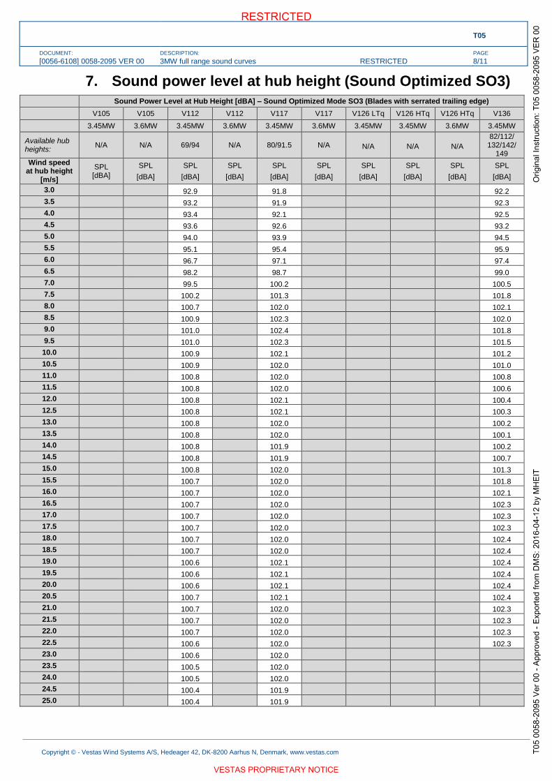
T05
DOCUMENT:
[0056-6108] 0058-2095 VER 00
DESCRIPTION:
3MW full range sound curves RESTRICTED
PAGE
8/11
Copyright © - Vestas Wind Systems A/S, Hedeager 42, DK-8200 Aarhus N, Denmark, www.vestas.com
7. Sound power level at hub height (Sound Optimized SO3)
Sound Power Level at Hub Height [dBA] – Sound Optimized Mode SO3 (Blades with serrated trailing edge)
V105 V105 V112 V112 V117 V117 V126 LTq V126 HTq V126 HTq V136
3.45MW 3.6MW 3.45MW 3.6MW 3.45MW 3.6MW 3.45MW 3.45MW 3.6MW 3.45MW
Available hub heights:
N/A N/A 69/94 N/A 80/91.5 N/A N/A N/A N/A 82/112/
132/142/ 149
Wind speed at hub height
[m/s]
SPL [dBA]
SPL
[dBA]
SPL
[dBA]
SPL
[dBA]
SPL
[dBA]
SPL
[dBA]
SPL
[dBA]
SPL
[dBA]
SPL
[dBA]
SPL
[dBA]
3.0 92.9 91.8 92.2
3.5 93.2 91.9 92.3
4.0 93.4 92.1 92.5
4.5 93.6 92.6 93.2
5.0 94.0 93.9 94.5
5.5 95.1 95.4 95.9
6.0 96.7 97.1 97.4
6.5 98.2 98.7 99.0
7.0 99.5 100.2 100.5
7.5 100.2 101.3 101.8
8.0 100.7 102.0 102.1
8.5 100.9 102.3 102.0
9.0 101.0 102.4 101.8
9.5 101.0 102.3 101.5
10.0 100.9 102.1 101.2
10.5 100.9 102.0 101.0
11.0 100.8 102.0 100.8
11.5 100.8 102.0 100.6
12.0 100.8 102.1 100.4
12.5 100.8 102.1 100.3
13.0 100.8 102.0 100.2
13.5 100.8 102.0 100.1
14.0 100.8 101.9 100.2
14.5 100.8 101.9 100.7
15.0 100.8 102.0 101.3
15.5 100.7 102.0 101.8
16.0 100.7 102.0 102.1
16.5 100.7 102.0 102.3
17.0 100.7 102.0 102.3
17.5 100.7 102.0 102.3
18.0 100.7 102.0 102.4
18.5 100.7 102.0 102.4
19.0 100.6 102.1 102.4
19.5 100.6 102.1 102.4
20.0 100.6 102.1 102.4
20.5 100.7 102.1 102.4
21.0 100.7 102.0 102.3
21.5 100.7 102.0 102.3
22.0 100.7 102.0 102.3
22.5 100.6 102.0 102.3
23.0 100.6 102.0
23.5 100.5 102.0
24.0 100.5 102.0
24.5 100.4 101.9
25.0 100.4 101.9

T05
DOCUMENT:
[0056-6108] 0058-2095 VER 00
DESCRIPTION:
3MW full range sound curves RESTRICTED
PAGE
9/11
Copyright © - Vestas Wind Systems A/S, Hedeager 42, DK-8200 Aarhus N, Denmark, www.vestas.com
8. Sound power level at hub height (Sound Optimized SO4)
Sound Power Level at Hub Height [dBA] – Sound Optimized Mode SO4 (Blades with serrated trailing edge)
V105 V105 V112 V112 V117 V117 V126 LTq V126 HTq V126 HTq V136
3.45MW 3.6MW 3.45MW 3.6MW 3.45MW 3.6MW 3.45MW 3.45MW 3.6MW 3.45MW
Available hub heights:
N/A N/A 69/94 N/A 80/91.5/ (116.5 IEC1B)
N/A N/A N/A N/A 82/112/
132/142/ 149
Wind speed at hub height
[m/s]
SPL [dBA]
SPL
[dBA]
SPL
[dBA]
SPL
[dBA]
SPL
[dBA]
SPL
[dBA]
SPL
[dBA]
SPL
[dBA]
SPL
[dBA]
SPL
[dBA]
3.0 92.9 91.8 92.2
3.5 93.2 91.9 92.3
4.0 93.4 92.1 92.5
4.5 93.6 92.6 93.2
5.0 94.0 93.9 94.5
5.5 95.1 95.4 95.9
6.0 96.7 97.0 97.4
6.5 98.2 98.6 98.0
7.0 99.6 99.7 97.7
7.5 100.7 99.8 97.4
8.0 101.4 99.6 97.2
8.5 101.9 99.3 97.0
9.0 102.2 99.0 96.9
9.5 102.6 98.8 96.8
10.0 103.0 98.7 96.7
10.5 103.4 98.5 96.6
11.0 103.6 98.3 96.5
11.5 103.7 98.2 96.4
12.0 103.8 98.1 96.3
12.5 103.9 98.0 96.2
13.0 103.9 97.9 96.2
13.5 103.8 97.8 96.1
14.0 103.7 97.7 96.0
14.5 103.6 97.6 96.0
15.0 103.4 97.5 95.9
15.5 103.3 97.5 95.9
16.0 103.2 97.4 95.8
16.5 103.0 97.3 95.8
17.0 102.9 97.3 95.7
17.5 102.8 97.2 95.7
18.0 102.7 97.2 95.6
18.5 102.6 97.1 95.6
19.0 102.5 97.1 95.6
19.5 102.4 97.0 95.5
20.0 102.3 97.0 95.5
20.5 102.2 97.0 95.5
21.0 102.2 96.9 95.4
21.5 102.1 96.8 95.4
22.0 102.0 96.8 95.4
22.5 101.9 96.8 95.3
23.0 101.9 96.8
23.5 101.8 96.7
24.0 101.7 96.7
24.5 101.7 96.7
25.0 101.6 96.6

T05
DOCUMENT:
[0056-6108] 0058-2095 VER 00
DESCRIPTION:
3MW full range sound curves RESTRICTED
PAGE
10/11
Copyright © - Vestas Wind Systems A/S, Hedeager 42, DK-8200 Aarhus N, Denmark, www.vestas.com
9. Sound power level at hub height (Sound Optimized SO5)
Sound Power Level at Hub Height [dBA] – Sound Optimized Mode SO5 (Blades with serrated trailing edge)
V105 V105 V112 V112 V117 V117 V126 LTq V126 HTq V126 HTq V136
3.45MW 3.6MW 3.45MW 3.6MW 3.45MW 3.6MW 3.45MW 3.45MW 3.6MW 3.45MW
Available hub heights: N/A N/A 69/94 N/A
80/91.5/ (116.5
IEC1B + IEC2A)
N/A N/A N/A N/A N/A
Wind speed at hub height
[m/s]
SPL [dBA]
SPL
[dBA]
SPL
[dBA]
SPL
[dBA]
SPL
[dBA]
SPL
[dBA]
SPL
[dBA]
SPL
[dBA]
SPL
[dBA]
SPL
[dBA]
3.0 92.9 91.8
3.5 93.2 91.9
4.0 93.4 92.1
4.5 93.6 92.6
5.0 94.0 93.9
5.5 95.1 95.4
6.0 96.6 96.9
6.5 98.1 98.0
7.0 99.3 98.7
7.5 99.8 99.0
8.0 100.0 99.9
8.5 100.0 101.2
9.0 99.7 102.3
9.5 99.3 102.8
10.0 99.0 103.0
10.5 98.7 103.3
11.0 98.6 103.6
11.5 98.6 103.9
12.0 98.6 104.2
12.5 98.6 104.3
13.0 98.6 104.4
13.5 98.7 104.3
14.0 98.7 104.3
14.5 98.8 104.2
15.0 98.9 104.2
15.5 98.9 104.1
16.0 98.9 104.0
16.5 99.0 104.0
17.0 99.0 104.0
17.5 99.1 104.0
18.0 99.1 104.0
18.5 99.1 104.1
19.0 99.1 104.1
19.5 99.1 104.1
20.0 99.2 104.1
20.5 99.2 104.1
21.0 99.2 104.1
21.5 99.2 104.0
22.0 99.2 104.0
22.5 99.1 103.9
23.0 99.1 103.9
23.5 99.1 103.8
24.0 99.0 103.8
24.5 99.0 103.7
25.0 98.9 103.7

T05
DOCUMENT:
[0056-6108] 0058-2095 VER 00
DESCRIPTION:
3MW full range sound curves RESTRICTED
PAGE
11/11
Copyright © - Vestas Wind Systems A/S, Hedeager 42, DK-8200 Aarhus N, Denmark, www.vestas.com
10. Additional remarks
The listed sound power curves are only valid for the designated operating modes and for the
designated hub heights.

Document no.: 961763 V02
Weight, Dimensions and Centre of Gravity of 44 m
Blades
Date: 2010-09-27
Issued by: Technology R&D Class: 1
Type: T009 - Manual Page 1 of 3
Vestas Wind Systems A/S · Alsvej 21 · 8940 Randers SV · Denmark · www.vestas.com
QM
S 0
0084 V
00 2
008-0
9-0
1
Weight, Dimensions and Centre of Gravity of 44 m Blades
Table of Contents
1 Purpose ................................................................................................................................ 2 2 Reference Documents ......................................................................................................... 2 3 Abbreviations and Technical Terms ................................................................................... 2 4 Technical Data ..................................................................................................................... 3 4.1 44 m Prepreg Blades ............................................................................................................. 3 4.2 44 m Wood Carbon Blades .................................................................................................... 3
VESTAS PROPRIETARY NOTICE: This document contains valuable confidential information of Vestas Wind Systems A/S. It is protected by copyright law as an unpublished work. Vestas reserves all patent, copyright, trade secret, and other proprietary rights to it. The information in this document may not be used, reproduced, or disclosed except if and to the extent rights are expressly granted by Vestas in writing and subject to applicable conditions. Vestas disclaims all warranties except as expressly granted by written agreement and is not responsible for unauthorized uses, for which it may pursue legal remedies against responsible parties.

Document no.: 961763 V02 Weight, Dimensions and Centre of Gravity of 44 m
Blades
Purpose
Date: 2010-09-27
Issued by: Technology R&D Class: 1
Type: T09 - Manual Page 2 of 3
Vestas Wind Systems A/S · Alsvej 21 · 8940 Randers SV · Denmark · www.vestas.com
1 Purpose
This document describes the weight, dimensions and centre of gravity of 44 m
prepreg and WCT blades with and without HJ frames.
During transportation, this document must be used together with the transport
manual for the specific turbine type and Mk version.
During installation, this document must be used together with the installation
manual for the specific turbine type and Mk version.
2 Reference Documents
Transport manual for the specific turbine type and Mk version.
Installation manual for the specific turbine type and Mk version.
All relevant documentation must be read and understood before handling and
transporting/installing blades.
3 Abbreviations and Technical Terms
Abbreviation Spelled-out form / explanation
L Length of the blades.
Whj Width in HJ frames/upright position.
H Maximum height of the blades.
Lc Distance to the maximum chord of the blades.
Lcg Distance to the centre of gravity.
W Weight.
R.1000 Edge of threaded insert in the root end (mm).
This is the starting point for measuring correct lifting point at
tip end.
Table 3-1: Abbreviations.
Term Explanation
WCT Wood Carbon Technology.
Prepreg Pre-impregnated.
Table 3-2: Explanation of terms.
NOTE

Document no.: 961763 V02 Weight, Dimensions and Centre of Gravity of 44 m
Blades
Technical Data
Date: 2010-09-27
Issued by: Technology R&D Class: 1
Type: T09 - Manual Page 3 of 3
Vestas Wind Systems A/S · Alsvej 21 · 8940 Randers SV · Denmark · www.vestas.com
4 Technical Data
Figure 4-1: 44 m blade.
4.1 44 m Prepreg Blades
Component L
[mm]
Whj
[mm]
H
[mm]
Lc
[mm]
Lcg
[mm]
W
[kg]
Blades
44000 1800 3512 9000 11200 6700
Blades
including
transport
frames (HJ)
44150 2440 3300 9000 11700 7900
Table 4-1: Technical data 44 m prepreg blade.
4.2 44 m Wood Carbon Blades
Component L
[mm]
Whj
[mm]
H
[mm]
Lc
[mm]
Lcg
[mm]
W
[kg]
Blades
44000 1800 3499 9000 13000 7050
Blades
including
transport
frames (HJ)
44150 2440 3300 9000 13500 8250
Table 4-2: Technical data 44 m wood carbon blade.
R.1000

Bijlage 2-2c –
Specificaties Enercon E92
NL68901
Typewritten Text
Deze bijlage geldt voor alle drie de aangevraagde Enercon E92 windturbines. Deze windturbines zijn nagenoeg identiek, alleen de masthoogte varieert te weten 78, 85 en 85 meter hoog.

Technical DescriptionENERCON Wind Energy ConverterE-92 2000/2350 kW

Legal notice
Publisher ENERCON GmbH ▪ Dreekamp 5 ▪ 26605 Aurich ▪ GermanyPhone: +49 4941 927-0 ▪ Fax: +49 4941 927-109E-mail: [email protected] ▪ Internet: http://www.enercon.deManaging Directors: Hans-Dieter Kettwig, Nicole Fritsch-NehringLocal court: Aurich ▪ Company registration number: HRB 411VAT ID no.: DE 181 977 360
Copyright notice The entire content of this document is protected by the German Copyright Act(UrhG) and international agreements.All copyrights concerning the content of this document are held by ENERCONGmbH, unless another copyright holder is expressly indicated or identified.Any content made available does not grant the user any industrial property rights,rights of use or any other rights. The user is not allowed to register any intellectualproperty rights or rights for parts thereof.Any transmission, surrender and distribution of the contents of this document tothird parties, any reproduction or copying, and any application and use - also in part- require the express and written permission of the copyright holder, unless any ofthe above are permitted by mandatory legal regulations.Any infringement of the copyright is contrary to law, may be prosecuted accordingto §§ 106 et seq. of the German Copyright Act (UrhG), and grants the copyrightholder the right to file for injunctive relief and to claim for punitive damages.
Registered trademarks Any trademarks mentioned in this document are intellectual property of the respec-tive registered trademark holders; the stipulations of the applicable trademark laware valid without restriction.
Reservation of rightof modification
ENERCON GmbH reserves the right to change, improve and expand this documentand the subject matter described herein at any time without prior notice, unless con-tractual agreements or legal requirements provide otherwise.
Document information
Document ID D0374244-3Notation Original document. Source document of this translation: D0279978-3.
Date Language DCC Plant / department2015-02-04 eng DA WRD GmbH / Documentation Department
Legal notice
ii D0374244-3 / DA

Table of contents
1 Overview of ENERCON E-92 2 MW/2.35 MW ...................................................... 1
2 ENERCON wind energy converter concept .......................................................... 2
3 E-92 components .................................................................................................. 3
3.1 Rotor blades .......................................................................................................... 33.2 Nacelle .................................................................................................................. 4
3.2.1 Annular generator ................................................................................. 43.3 Tower .................................................................................................................... 4
4 Grid Management System .................................................................................... 6
5 Safety system ....................................................................................................... 8
5.1 Safety equipment ................................................................................................. 85.2 Sensor system ...................................................................................................... 8
6 Control system ...................................................................................................... 11
6.1 Yaw system ........................................................................................................... 116.2 Pitch control .......................................................................................................... 116.3 WEC start .............................................................................................................. 12
6.3.1 Start lead-up ......................................................................................... 126.3.2 Wind measurement and nacelle alignment .......................................... 126.3.3 Generator excitation .............................................................................. 136.3.4 Power feed ............................................................................................ 13
6.4 Operating modes .................................................................................................. 146.4.1 Full load operation ................................................................................ 146.4.2 Partial load operation ............................................................................ 156.4.3 Idle mode .............................................................................................. 15
6.5 Safe stopping of the wind energy converter .......................................................... 16
7 Remote monitoring ................................................................................................ 17
8 Maintenance ......................................................................................................... 18
9 Technical specifications E-92 2 MW/2.35 MW ...................................................... 19
Table of contents
D0374244-3 / DA iii

Table of contents
iv D0374244-3 / DA
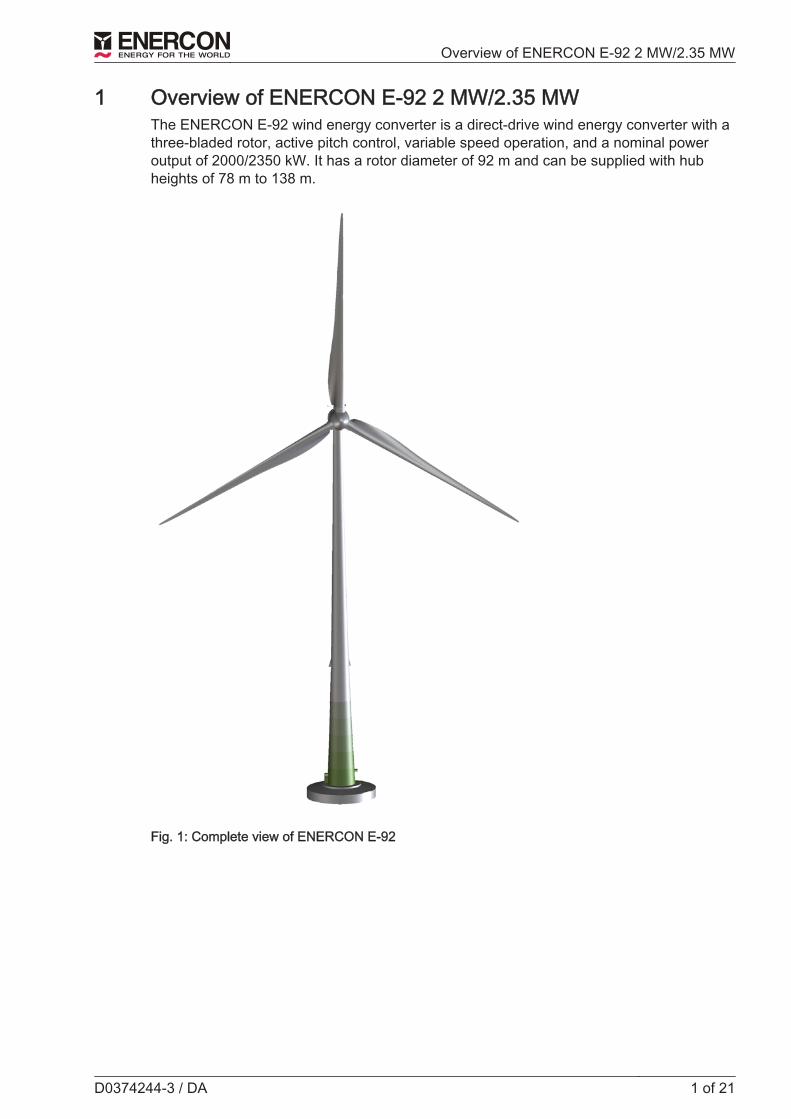
1 Overview of ENERCON E-92 2 MW/2.35 MW
The ENERCON E-92 wind energy converter is a direct-drive wind energy converter with athree-bladed rotor, active pitch control, variable speed operation, and a nominal poweroutput of 2000/2350 kW. It has a rotor diameter of 92 m and can be supplied with hubheights of 78 m to 138 m.
Fig. 1: Complete view of ENERCON E-92
Overview of ENERCON E-92 2 MW/2.35 MW
D0374244-3 / DA 1 of 21

2 ENERCON wind energy converter concept
ENERCON wind energy converters are characterised by the following features:
GearlessThe E-92 drive system comprises very few rotating components. The rotor hub and therotor of the annular generator are directly interconnected to form one solid unit. This re‐duces the mechanical strain and increases technical service life. Maintenance and servicecosts are reduced (fewer wearing parts, no gear oil change, etc.) and operating expensesalso decrease. Since there are no gears or other fast rotating parts, the energy loss be‐tween generator and rotor as well as noise emissions are considerably reduced.
Active pitch controlEach of the three rotor blades is equipped with a pitch unit. Each pitch unit consists of anelectrical drive, a control system, and a dedicated emergency power supply. The pitchunits limit the rotor speed and the amount of power extracted from the wind. In this way,the maximum output of the E-92 can be accurately limited to nominal power, even at shortnotice. By pitching the rotor blades into the feathered position, the rotor is stopped withoutany strain on the drive train caused by the application of a mechanical brake.
Indirect grid connectionThe power produced by the annular generator is fed into the distribution or transport gridvia the ENERCON Grid Management System. The ENERCON Grid Management System,which consists of a rectifier, a DC link and a modular inverter system, ensures maximumenergy yield with excellent power quality. The electrical properties of the annular genera‐tor are therefore irrelevant to the behaviour of the wind energy converter in the distributionor transport grid. Rotational speed, excitation, output voltage and output frequency of theannular generator may vary depending on the wind speed. In this way, the energy con‐tained in the wind can be optimally exploited even in the partial load range.
ENERCON wind energy converter concept
2 of 21 D0374244-3 / DA

3 E-92 components
Fig. 2: View of ENERCON E-92 nacelle
1 Slip ring unit 8 Generator filter cabinet
2 Rotor hub 9 Excitation controller box
3 Blade adapter 10 Nacelle converter cabinet
4 Generator stator 11 Yaw drives
5 Generator rotor 12 Main carrier
6 Stator shield 13 Blade extension
7 Rectifier cabinet 14 Rotor blade
3.1 Rotor blades
The rotor blades made of glass-fibre reinforced plastic (glass fibre + epoxy resin) have amajor influence on the wind energy converter’s yield and its noise emission. The shapeand profile of the E-92 rotor blades were designed with the following criteria in mind:■ High power coefficient■ Long service life■ Low noise emissions■ Low mechanical strain■ Efficient use of material
E-92 components
D0374244-3 / DA 3 of 21

One special feature to be pointed out is the new rotor blade profile, which extends down tothe nacelle. This design eliminates the loss of the inner air flow experienced with conven‐tional rotor blades. In combination with the streamlined nacelle, utilisation of the wind sup‐ply is considerably optimised.The rotor blades of the E-92 were specially designed to operate with variable pitch controland at variable speeds. The PU-based surface coating protects the rotor blades from envi‐ronmental impacts such as UV radiation and erosion. This coating is highly resistant toabrasion and visco-hard.Microprocessor-controlled pitch units that are independent of one another adjust each ofthe three rotor blades. An angle encoder in each rotor blade constantly monitors the setblade angle and ensures blade angle synchronisation across all three blades. This pro‐vides for quick, accurate adjustment of blade angles according to the prevailing wind con‐ditions.
3.2 Nacelle
3.2.1 Annular generator
ENERCON wind energy converters (WECs) are equipped with a multi-polar, separatelyexcited synchronous generator (annular generator). The WEC operates at variablespeeds so as to optimally utilise the wind energy potential. The annular generator there‐fore produces alternating current with varying voltage, frequency and amplitude.The windings in the stator of the annular generator form two three-phase alternating cur‐rent systems that are independent of each other. Both systems are rectified independentlyof each other in the nacelle and combined by the direct-current distribution system. In thetower base the inverters reconvert the current into three-phase current whose voltage, fre‐quency, and phase position conform to the grid.Consequently, the annular generator is not directly connected to the receiving power gridof the utility/power supply company; instead, it is completely decoupled from the grid bythe full-scale converter.
3.3 Tower
The tower of the E-92 wind energy converter is either a steel tower or a concrete towermade of precast segments. Towers with different heights are available.All towers are painted and equipped with weather and corrosion protection at the factory.This means that no work is required in this regard after assembly except for repairing anydefects or transport damage. By default, the bottom of the tower comes with graduatedpaintwork (can be dispensed with if desired).Steel towers are steel tubes that taper linearly towards the top. They are prefabricatedand consist of a small number of large sections. Flanges with drill holes for bolting arewelded to the ends of the sections.The tower sections are simply stacked on top of each other and bolted together at the in‐stallation site. They are linked to the foundation by means of a bolt cage.The concrete tower is assembled from the precast concrete elements at the installationsite. As a rule, segments are dry-stacked; however, a compensatory grout layer can beapplied. Vertical joints are closed by means of bolt connections.Towers are pre-tensioned vertically by means of prestressing steel tendons. The pre‐stressing tendons run vertically either through ducts in the concrete elements or externallyalong the interior tower wall. They are anchored to the foundation.
E-92 components
4 of 21 D0374244-3 / DA

For technical and financial reasons, the top slender part of the E-92 concrete tower ismade of steel. For instance, installing the yaw bearing directly on the concrete elements isunfeasible, and the considerably thinner wall of the steel section provides for more spacein the tower interior.
E-92 components
D0374244-3 / DA 5 of 21

4 Grid Management System
The annular generator is coupled to the grid through the ENERCON Grid ManagementSystem. The main components of this system are a rectifier, a DC link, and several modu‐lar inverters.
Annular
generatorRectifier DC link Inverter Filters Transformer
Power circuit
breakerGrid
ENERCON control system
Excitation controller
Fig. 3: Simplified electric diagram of an ENERCON WEC
The Grid Management System, generator excitation and pitch control are all managed bythe control system to achieve maximum energy yield and excellent power quality.Decoupling the annular generator from the grid guarantees ideal power transmission con‐ditions. Sudden changes in wind speed are translated into controlled change in order tomaintain stable grid feed. Conversely, possible grid faults have virtually no effect on WECmechanics. The power injected by the E-92 can be precisely regulated from 0 kW to2000/2350 kW.In general, the features required for a certain wind energy converter or wind farm to beconnected to the receiving power grid are predefined by the operator of that grid. To meetdifferent requirements, ENERCON wind energy converters are available with differentconfigurations.The inverter system in the tower base is dimensioned according to the particular WECconfiguration. As a rule, a transformer inside or near the wind energy converter converts400 V low voltage to the desired medium voltage.
Reactive powerIf necessary, an E-92 equipped with standard FACTS (Flexible AC Transmission System)control can supply reactive power in order to contribute to reactive power balance and tomaintaining voltage levels in the grid. The maximum reactive power range is available atan output as low as 10 % of the nominal active power. The maximum reactive powerrange varies, depending on the WEC configuration.
Grid Management System
6 of 21 D0374244-3 / DA

FT configurationBy default, the E-92 comes equipped with FACTS technology that meets the stringent re‐quirements of specific grid codes. It is able to ride through grid faults (undervoltage, over‐voltage, automatic reclosing, etc.) of up to 5 seconds (FT = FACTS + FRT [Fault RideThrough]) and to remain connected to the grid during these faults.If the voltage measured at the reference point exceeds a defined limit value, theENERCON wind energy converter changes from normal operation to a specific fault oper‐ating mode.Once the fault has been cleared, the wind energy converter returns to normal operationand feeds the available power into the grid. If the voltage does not return to the operatingrange admissible for normal operation within an adjustable time frame (5 seconds max.),the wind energy converter is disconnected from the grid.While the system is riding through a grid fault, various fault modes using different grid feedstrategies are available, including feeding in additional reactive current in the event of afault. The control strategies include different options for setting fault types.Selection of a suitable control strategy depends on specific grid code and project require‐ments that must be confirmed by the particular grid operator.
FTQ configurationThe FTQ configuration (FT plus Q+ option) comprises all features of the FT configuration.In addition, it has an extended reactive power range.
FTQS configurationThe FTQS configuration comprises all features of the FTQ configuration and has been ex‐panded to include the STATCOM (Static Synchronous Compensator) option. TheSTATCOM option enables the wind energy converter to output and absorb reactive powerregardless of whether it generates and feeds active power into the grid. It is thus able toactively support the power grid at any time, similar to a power plant.
Frequency protectionENERCON wind energy converters can be used in grids with a nominal frequency of50 Hz or 60 Hz.The range of operation of the E-92 is defined by a lower and upper frequency limit value.Overfrequency and underfrequency events at the WEC reference point trigger frequencyprotection and cause the WEC to shut down after the maximum delay time of 60 secondshas elapsed.
Power-frequency controlIf temporary overfrequency occurs as a result of a grid fault, ENERCON wind energy con‐verters can reduce their power feed dynamically to contribute to restoring the balance be‐tween the generating and transmission networks. As a pre-emptive measure, the active power feed of ENERCON wind energy converterscan be limited during normal operation. During an underfrequency event, the power re‐served by this limitation is made available to stabilise the frequency. The characteristics ofthis control system can be easily adapted to different specifications.
Grid Management System
D0374244-3 / DA 7 of 21

5 Safety system
The E-92 comes with a large number of safety features whose purpose is to permanentlykeep the WEC inside a safe operating range. In addition to components that ensure safestopping of the wind energy converter, these include a complex sensor system. It continu‐ously captures all relevant operating states of the wind energy converter and makes therelevant information available through the ENERCON SCADA remote monitoring system.If any safety-relevant operating parameters are out of the permitted range, the WEC willcontinue running at limited power or it will stop.
5.1 Safety equipment
Emergency stop buttonIn an ENERCON wind energy converter there are emergency stop buttons next to thetower door, on the control cabinet in the tower base, on the nacelle control cabinet and, ifrequired, on further levels of the E-module. Actuating an emergency stop button activatesthe rotor brake. Emergency pitching of the rotor blades takes place.The following are still supplied with power:■ Rotor brake■ Beacon system components■ Lighting■ Sockets
Main switchIn an ENERCON wind energy converter, main switches are installed on the control cabi‐net and the nacelle control cabinet. When actuated, they de-energise virtually the entirewind energy converter.The following are still supplied with power:■ Beacon system components■ Service hoist■ Sockets■ Lighting■ Medium-voltage area
5.2 Sensor system
There is a large number of sensors that continuously monitor the current status of thewind energy converter and the relevant ambient parameters (e.g. rotor speed, tempera‐ture, blade load, etc.). The control system analyses the signals and regulates the wind en‐ergy converter such that the wind energy available at any given time is always optimallyexploited and operating safety is ensured at the same time.
Redundant sensorsIn order to be able to check plausibility by comparing the reported values, more sensorsthan necessary are installed for some operating states (e.g. for measuring the generatortemperature). Defective sensors are reliably detected and can be replaced by activation ofa spare sensor. In this way, the wind energy converter can safely continue its operationwithout the need for replacement of major components.
Safety system
8 of 21 D0374244-3 / DA


![Prepreg technology[1]](https://static.fdocuments.in/doc/165x107/5550156eb4c90535638b4d56/prepreg-technology1.jpg)