4045-6068+Electronicos,+Manual+Servicio
678
John Deere Diesel engines Powertech 4.5L and 6.8L Level 11 Fuel systems with Denso HPCR CTM 220 (21Jan04) 33525067201_2_1 Workshop manual
-
Upload
jhon-jairo-trujillo -
Category
Documents
-
view
26 -
download
0
Transcript of 4045-6068+Electronicos,+Manual+Servicio

John Deere Diesel engines
Powertech 4.5L and 6.8L Level 11 Fuel systems
with Denso HPCR
CTM 220 (21Jan04) 33525067201_2_1
Workshop manual


POWERTECH 4.5L & 6.8LDiesel Engines
Level 11 ElectronicFuel System With
Denso HPCR
TECHNICAL MANUALPOWERTECH 4.5 L & 6.8 L Diesel
Engines—Level 11 Electronic FuelSystem with Denso HPCR
CTM220 21JAN04 (ENGLISH)
For complete service information also see:
POWERTECH 4.5 L and 6.8 L DieselEngines—Base Engine . . . . . . . . . . . . . . . . . CTM104Alternators and Starter Motors. . . . . . . . . . . CTM77OEM Engine Accessories . . . . . . CTM67 (English Only)
John Deere Power Systems
LITHO IN U.S.A.

Introduction
RG40854,0000001 –19–10APR02–1/1
Forward
This manual is written for an experienced technician.Essential tools required in performing certain servicework are identified in this manual and arerecommended for use.
This manual (CTM220) covers only Level 11 ElectronicFuel System with the Denso High Pressure CommonRail (HPCR). It is one of six volumes on 4.5 L and 6.8L engines. The following five companion manualscover the base engine, mechanical fuel system, andother electronic control systems. Each manual coversrepair, operation, and diagnostics.
• CTM104—Base Engine• CTM170—Level 4 Electronic Fuel System with
Bosch VP44 Pump• CTM207—Mechanical Fuel Systems• CTM284—Level 1 Electronic Fuel System with
Delphi (Lucas) DP201 Pump• CTM331—Level 12 Electronic Fuel System with
Stanadyne DE 10 Pump
Other manuals will be added in the future to provideadditional information on electronic fuel systems asneeded.
A complete set of all these manuals covering 4.5 Land 6.8 L engines is available in a binder by orderingCTM 350 Binder Set.
Live with safety: Read the safety messages in theintroduction of this manual and the cautions presentedthroughout the text of the manual.
This is the safety-alert symbol. When you see thissymbol on the machine or in this manual, be alert tothe potential for personal injury.
Use this component technical manual in conjunctionwith the machine technical manual. An application
listing in Section 01, Group 001 identifiesproduct-model/component type-model relationship. Seethe machine technical manual for information oncomponent removal and installation, and gainingaccess to the components.
Information is organized in sections and groups for thevarious components requiring service instruction. Atthe beginning of each group are summaries of the upcoming group.
Before beginning repair on an engine, clean theengine.
This manual contains SI Metric units of measurefollowed immediately by the U.S. customary units ofmeasure. Most hardware on these engines are metricsized.
Some components of this engine may be servicedwithout removing the engine from the machine. Referto the specific machine technical manual forinformation on components that can be servicedwithout removing the engine from the machine and forengine removal and installation procedures.
Read each block of material completely beforeperforming service to check for differences inprocedures or specifications. Follow only theprocedures that apply to the engine model number youare working on. If only one procedure is given, thatprocedure applies to all the engines in the manual.
CALIFORNIA PROPOSITION 65 WARNING: Dieselengine exhaust and some of its constituents areknown to the State of California to cause cancer,birth defects, and other reproductive harm.
CTM220 (21JAN04) 4.5 L & 6.8 L Level 11 Electronic Fuel System012104
PN=2

Contents01
SECTION 01—GeneralGroup 000—SafetyGroup 001—Engine IdentificationGroup 002—Fuels, Lubricants, and Coolant
02SECTION 02—Repair and AdjustmentsGroup 090—Electronic Fuel System Repair and
AdjustmentsGroup 110—Electronic Engine Control Repair and
Adjustment
SECTION 03—Theory Of OperationGroup 130—Electronic Fuel System OperationGroup 140—Electronic Control System Operation
SECTION 04—Diagnostics
03
Group 150—Observable Diagnostics and TestsGroup 160—Trouble Code Diagnostics and Tests
SECTION 05—ToolsGroup 170—Electronic Fuel/Control System Repair
Tools and Other MaterialsGroup 180—Diagnostic Service Tools
SECTION 06—SpecificationsGroup 200—Repair SpecificationsGroup 210—Diagnostic Specifications
04
05
All information, illustrations and specifications in this manual are based onthe latest information available at the time of publication. The right isreserved to make changes at any time without notice.
06
COPYRIGHT 2002DEERE & COMPANY
Moline, IllinoisAll rights reserved
A John Deere ILLUSTRUCTION Manual
INDX
CTM220 (21JAN04) i 4.5 L & 6.8 L Level 11 Electronic Fuel System012104
PN=1

Contents
01
02
03
04
05
06
INDX
CTM220 (21JAN04) ii 4.5 L & 6.8 L Level 11 Electronic Fuel System012104
PN=2

01
Section 01General
Contents
Page
Group 000—Safety . . . . . . . . . . . . . . . . . . . .01-000-1
Group 001—Engine IdentificationEngine Model Designation. . . . . . . . . . . . . . . .01-001-1Engine Serial Number Plate Information . . . . .01-001-2OEM Engine Option Code Label . . . . . . . . . . .01-001-3Information Relative to Emissions
Regulations . . . . . . . . . . . . . . . . . . . . . . . . .01-001-3Engine Application Charts . . . . . . . . . . . . . . . .01-001-4
Group 002—Fuels, Lubricants, and CoolantLubricants and Coolant . . . . . . . . . . . . . . . . . .01-002-1Diesel Fuel . . . . . . . . . . . . . . . . . . . . . . . . . . .01-002-1Bio-Diesel Fuel . . . . . . . . . . . . . . . . . . . . . . . .01-002-2Dieselscan Fuel Analysis. . . . . . . . . . . . . . . . .01-002-2Lubricity of Diesel Fuel . . . . . . . . . . . . . . . . . .01-002-3
CTM220 (21JAN04) 01-1 4.5 L & 6.8 L Level 11 Electronic Fuel System012104
PN=1

Contents
01
CTM220 (21JAN04) 01-2 4.5 L & 6.8 L Level 11 Electronic Fuel System012104
PN=2

Group 000Safety
010001
DX,FLAME –19–29SEP98–1/1
Handle Fluids Safely—Avoid Fires
TS
227
–UN
–23A
UG
88
When you work around fuel, do not smoke or work nearheaters or other fire hazards.
Store flammable fluids away from fire hazards. Do notincinerate or puncture pressurized containers.
Make sure machine is clean of trash, grease, and debris.
Do not store oily rags; they can ignite and burnspontaneously.
DX,FIRE3 –19–16APR92–1/1
Handle Starting Fluid Safely
TS
1356
–UN
–18M
AR
92
Starting fluid is highly flammable.
Keep all sparks and flame away when using it. Keepstarting fluid away from batteries and cables.
To prevent accidental discharge when storing thepressurized can, keep the cap on the container, and storein a cool, protected location.
Do not incinerate or puncture a starting fluid container.
DX,RCAP –19–04JUN90–1/1
Service Cooling System Safely
TS
281
–UN
–23A
UG
88
Explosive release of fluids from pressurized coolingsystem can cause serious burns.
Shut off engine. Only remove filler cap when cool enoughto touch with bare hands. Slowly loosen cap to first stopto relieve pressure before removing completely.
CTM220 (21JAN04) 01-000-1 4.5 L & 6.8 L Level 11 Electronic Fuel System012104
PN=7

Safety
01000
2
DX,SPARKS –19–03MAR93–1/1
Prevent Battery Explosions
TS
204
–UN
–23A
UG
88
Keep sparks, lighted matches, and open flame away fromthe top of battery. Battery gas can explode.
Never check battery charge by placing a metal objectacross the posts. Use a volt-meter or hydrometer.
Do not charge a frozen battery; it may explode. Warmbattery to 16°C (60°F).
DX,FIRE2 –19–03MAR93–1/1
Prepare for Emergencies
TS
291
–UN
–23A
UG
88
Be prepared if a fire starts.
Keep a first aid kit and fire extinguisher handy.
Keep emergency numbers for doctors, ambulance service,hospital, and fire department near your telephone.
CTM220 (21JAN04) 01-000-2 4.5 L & 6.8 L Level 11 Electronic Fuel System012104
PN=8

Safety
010003
DPSG,OUO1004,2758 –19–11MAY00–1/1
Handling Batteries Safely
TS
204
–UN
–23A
UG
88T
S20
3–U
N–2
3AU
G88
CAUTION: Battery gas can explode. Keepsparks and flames away from batteries. Use aflashlight to check battery electrolyte level.
Never check battery charge by placing a metalobject across the posts. Use a voltmeter orhydrometer.
Always remove grounded (-) battery clamp firstand replace it last.
CAUTION: Sulfuric acid in battery electrolyte ispoisonous. It is strong enough to burn skin, eatholes in clothing, and cause blindness ifsplashed into eyes.
Avoid the hazard by:
1. Filling batteries in a well-ventilated area.2. Wearing eye protection and rubber gloves.3. Avoiding breathing fumes when electrolyte is
added.4. Avoiding spilling or dripping electrolyte.5. Use proper jump start procedure.
If you spill acid on yourself:
1. Flush your skin with water.2. Apply baking soda or lime to help neutralize
the acid.3. Flush your eyes with water for 15—30
minutes. Get medical attention immediately.
If acid is swallowed:
1. Do not induce vomiting.2. Drink large amounts of water or milk, but do
not exceed 2 L (2 quarts).3. Get medical attention immediately.
WARNING: Battery posts, terminals, and relatedaccessories contain lead and lead compounds, chemicalsknown to the State of California to cause cancer andreproductive harm. Wash hands after handling.
CTM220 (21JAN04) 01-000-3 4.5 L & 6.8 L Level 11 Electronic Fuel System012104
PN=9
Safety
01000
4
DX,FLUID –19–03MAR93–1/1
Avoid High-Pressure Fluids
X98
11–U
N–2
3AU
G88
Escaping fluid under pressure can penetrate the skincausing serious injury.
Avoid the hazard by relieving pressure beforedisconnecting hydraulic or other lines. Tighten allconnections before applying pressure.
Search for leaks with a piece of cardboard. Protect handsand body from high pressure fluids.
If an accident occurs, see a doctor immediately. Any fluidinjected into the skin must be surgically removed within afew hours or gangrene may result. Doctors unfamiliar withthis type of injury should reference a knowledgeablemedical source. Such information is available from Deere& Company Medical Department in Moline, Illinois, U.S.A.
DX,WEAR –19–10SEP90–1/1
Wear Protective Clothing
TS
206
–UN
–23A
UG
88
Wear close fitting clothing and safety equipmentappropriate to the job.
Prolonged exposure to loud noise can cause impairmentor loss of hearing.
Wear a suitable hearing protective device such asearmuffs or earplugs to protect against objectionable oruncomfortable loud noises.
Operating equipment safely requires the full attention ofthe operator. Do not wear radio or music headphoneswhile operating machine.
CTM220 (21JAN04) 01-000-4 4.5 L & 6.8 L Level 11 Electronic Fuel System012104
PN=10

Safety
010005
DX,LOOSE –19–04JUN90–1/1
Service Machines Safely
TS
228
–UN
–23A
UG
88
Tie long hair behind your head. Do not wear a necktie,scarf, loose clothing, or necklace when you work nearmachine tools or moving parts. If these items were to getcaught, severe injury could result.
Remove rings and other jewelry to prevent electricalshorts and entanglement in moving parts.
DX,AIR –19–17FEB99–1/1
Work In Ventilated Area
TS
220
–UN
–23A
UG
88
Engine exhaust fumes can cause sickness or death. If it isnecessary to run an engine in an enclosed area, removethe exhaust fumes from the area with an exhaust pipeextension.
If you do not have an exhaust pipe extension, open thedoors and get outside air into the area
DX,CLEAN –19–04JUN90–1/1
Work in Clean Area
T66
42E
J–U
N–1
8OC
T88
Before starting a job:
• Clean work area and machine.• Make sure you have all necessary tools to do your job.• Have the right parts on hand.• Read all instructions thoroughly; do not attempt
shortcuts.
CTM220 (21JAN04) 01-000-5 4.5 L & 6.8 L Level 11 Electronic Fuel System012104
PN=11

Safety
01000
6
DX,PAINT –19–22OCT99–1/1
Remove Paint Before Welding or Heating
TS
220
–UN
–23A
UG
88
Avoid potentially toxic fumes and dust.
Hazardous fumes can be generated when paint is heatedby welding, soldering, or using a torch.
Remove paint before heating:
• Remove paint a minimum of 76 mm (3 in.) from area tobe affected by heating.
• If you sand or grind paint, avoid breathing the dust.Wear an approved respirator.
• If you use solvent or paint stripper, remove stripper withsoap and water before welding. Remove solvent orpaint stripper containers and other flammable materialfrom area. Allow fumes to disperse at least 15 minutesbefore welding or heating.
Do all work in an area that is ventilated to carry toxicfumes and dust away.
Dispose of paint and solvent properly.
DX,TORCH –19–03MAR93–1/1
Avoid Heating Near Pressurized Fluid Lines
TS
953
–UN
–15M
AY
90
Flammable spray can be generated by heating nearpressurized fluid lines, resulting in severe burns toyourself and bystanders. Do not heat by welding,soldering, or using a torch near pressurized fluid lines orother flammable materials. Pressurized lines can beaccidentally cut when heat goes beyond the immediateflame area.
DX,LIGHT –19–04JUN90–1/1
Illuminate Work Area Safely
TS
223
–UN
–23A
UG
88
Illuminate your work area adequately but safely. Use aportable safety light for working inside or under themachine. Make sure the bulb is enclosed by a wire cage.The hot filament of an accidentally broken bulb can ignitespilled fuel or oil.
CTM220 (21JAN04) 01-000-6 4.5 L & 6.8 L Level 11 Electronic Fuel System012104
PN=12

Safety
010007
DX,LIFT –19–04JUN90–1/1
Use Proper Lifting Equipment
TS
226
–UN
–23A
UG
88
Lifting heavy components incorrectly can cause severeinjury or machine damage.
Follow recommended procedure for removal andinstallation of components in the manual.
DPSG,OUO1004,899 –19–19MAY99–1/1
Construct Dealer-Made Tools Safely
LX10
1674
9–U
N–0
1JU
L97
Construct Dealer-Made Tools Safely
Faulty or broken tools can result in serious injury. Whenconstructing tools, use proper, quality materials and goodworkmanship.
Do not weld tools unless you have the proper equipmentand experience to perform the job.
CTM220 (21JAN04) 01-000-7 4.5 L & 6.8 L Level 11 Electronic Fuel System012104
PN=13

Safety
01000
8
DX,SERV –19–17FEB99–1/1
Practice Safe Maintenance
TS
218
–UN
–23A
UG
88
Understand service procedure before doing work. Keeparea clean and dry.
Never lubricate, service, or adjust machine while it ismoving. Keep hands, feet , and clothing frompower-driven parts. Disengage all power and operatecontrols to relieve pressure. Lower equipment to theground. Stop the engine. Remove the key. Allow machineto cool.
Securely support any machine elements that must beraised for service work.
Keep all parts in good condition and properly installed. Fixdamage immediately. Replace worn or broken parts.Remove any buildup of grease, oil, or debris.
On self-propelled equipment, disconnect battery groundcable (-) before making adjustments on electrical systemsor welding on machine.
On towed implements, disconnect wiring harnesses fromtractor before servicing electrical system components orwelding on machine.
DX,REPAIR –19–17FEB99–1/1
Use Proper Tools
TS
779
–UN
–08N
OV
89Use tools appropriate to the work. Makeshift tools andprocedures can create safety hazards.
Use power tools only to loosen threaded parts andfasteners.
For loosening and tightening hardware, use the correctsize tools. DO NOT use U.S. measurement tools onmetric fasteners. Avoid bodily injury caused by slippingwrenches.
Use only service parts meeting John Deere specifications.
CTM220 (21JAN04) 01-000-8 4.5 L & 6.8 L Level 11 Electronic Fuel System012104
PN=14

Safety
010009
DX,DRAIN –19–03MAR93–1/1
Dispose of Waste Properly
TS
1133
–UN
–26N
OV
90
Improperly disposing of waste can threaten theenvironment and ecology. Potentially harmful waste usedwith John Deere equipment include such items as oil, fuel,coolant, brake fluid, filters, and batteries.
Use leakproof containers when draining fluids. Do not usefood or beverage containers that may mislead someoneinto drinking from them.
Do not pour waste onto the ground, down a drain, or intoany water source.
Air conditioning refrigerants escaping into the air candamage the Earth’s atmosphere. Government regulationsmay require a certified air conditioning service center torecover and recycle used air conditioning refrigerants.
Inquire on the proper way to recycle or dispose of wastefrom your local environmental or recycling center, or fromyour John Deere dealer.
DX,LIVE –19–25SEP92–1/1
Live With Safety
TS
231
–19–
07O
CT
88
Before returning machine to customer, make suremachine is functioning properly, especially the safetysystems. Install all guards and shields.
CTM220 (21JAN04) 01-000-9 4.5 L & 6.8 L Level 11 Electronic Fuel System012104
PN=15

Safety
01000
10
CTM220 (21JAN04) 01-000-10 4.5 L & 6.8 L Level 11 Electronic Fuel System012104
PN=16

Group 001Engine Identification
010011
RG40854,0000004 –19–10APR02–1/1
Engine Model Designation
John Deere Engine Model—4045 and 6068 Engines
John Deere engine model designation includes number ofcylinders, displacement in liters, aspiration, user code, andapplication code. For example:
4045TF275 Engine4 ................................................................ Number of cylinders4.5 ............................................................. Liter displacementT ............................................................... Aspiration codeF ............................................................... User code275 ............................................................ POWERTECH application codeAspiration CodeD ............................................................... Naturally aspiratedT ............................................................... Turbocharged, no aftercoolingA ............................................................... Turbocharged and Air-to-Coolant AftercooledH ............................................................... Turbocharged and Air-to-Air AftercooledUser Factory CodeAT ............................................................. Agritalia srl (Vittoria, Sicily, Italy)CQ ............................................................ John Deere Brazil (Horizontina, Brazil)DW ............................................................ John Deere Davenport Works (Davenport, Iowa)E ............................................................... John Deere Ottumwa Works (Ottumwa, Iowa)F ............................................................... OEM (Outside Equipment Manufacturers)FF ............................................................. Deere-Hitachi (Kernersville, North Carolina)FG ............................................................. Goldoni S.P.A. (Modena, Italy)FM ............................................................ Marine EnginesH ............................................................... John Deere Harvester Works (East Moline, Illinois)KV ............................................................. John Deere Commercial Worksite Products (Knoxville, Tennessee)L ................................................................ John Deere Werke Mannheim (Germany)LA ............................................................. John Deere Werke Mannheim (Germany) (Engines with Bosch VP44 Injection Pump)LV ............................................................. John Deere Commercial Products (Augusta, Georgia)N ............................................................... John Deere Des Moines Works (Des Moines, Iowa)P ............................................................... Industrias John Deere Mexico S.A. de C.V. (Saltillo/Monterrey, Mexico)PY ............................................................. Larson & Toubro Ltd. (Pune, India)RW ............................................................ John Deere Waterloo Tractor Works (Waterloo, Iowa)T ............................................................... John Deere Dubuque Works (Dubuque, Iowa)T8 ............................................................. Cameco Industries (Thibodaux, Louisiana)TJ .............................................................. Timberjack (Deere) (Sweden/Finland/Canada)YC ............................................................. John Deere Jialian Harvester Co. Limited (China)Z ............................................................... John Deere WERKE Zweibrucken (Germany)Application Code001, etc. .................................................... See ENGINE APPLICATION CHARTS, later in this Group
POWERTECH is a registered trademark of Deere & Company
CTM220 (21JAN04) 01-001-1 4.5 L & 6.8 L Level 11 Electronic Fuel System012104
PN=17

Engine Identification
01001
2
RG40854,0000005 –19–10APR02–1/1
Engine Serial Number Plate Information
RG
1181
6–U
N–1
5NO
V01
Engine Serial Number Plate
RG
9060
–UN
–16M
AR
98
Dubuque Engine Serial Number Plate
RG
1194
9–U
N–0
7NO
V01
Saran Engine Serial Number Plate
RG
1194
8–U
N–0
6NO
V01
Torreon Engine Serial Number Plate
A—Engine Serial Number PlateB—Engine Serial NumberC—Engine Application DataD—Coefficient of Absorption (Saran Engines Only)
IMPORTANT: The engine serial number plate (A) canbe easily destroyed. Before “hot tank”cleaning the block, remove the plate.
Engine Serial Number (B)
Each engine has a 13-digit John Deere engine serialnumber identifying the producing factory, engine modeldesignation, and a 6-digit sequential number. Thefollowing is an example:
CD4045T000000CD .......................... Factory producing engine4045T ..................... Engine model designation000000 ................... Sequential serial numberFactory Code (Engine Manufacturer)T0 ........................... Dubuque, IowaCD .......................... Saran, FrancePE .......................... Torreon, MexicoJ0 ........................... Rosario, ArgentinaEngine Model Designation4045T ..................... Definition explained previously. See ENGINE
MODEL DESIGNATION earlier in this group.Sequential Number000000 ................... 6-digit sequential serial number
Engine Application Data (C)
The second line of information on the serial number plateidentifies the engine/machine or OEM relationship. SeeENGINE APPLICATION CHARTS later in this group.
Coefficient of Absorption (D) — (Saran-Built EnginesOnly)
The second line of information on the Saran serial numberplate also contains the coefficient of absorption value forsmoke emissions.
CTM220 (21JAN04) 01-001-2 4.5 L & 6.8 L Level 11 Electronic Fuel System012104
PN=18

Engine Identification
010013
RG40854,0000006 –19–10APR02–1/1
OEM Engine Option Code Label
RG
1202
7–U
N–0
3DE
C01
An option code label is secured to the top of the valvecover and identifies the factory installed options on eachOEM engine to ensure correct parts acquisition.
Always provide option code information and engine basecode when ordering repair parts. A listing of option codesis given in parts catalogs and operator’s manuals.
NOTE: Before “hot tank” cleaning, ensure that optioncodes are recorded elsewhere.
RG40854,0000007 –19–10APR02–1/1
Information Relative to Emissions Regulations
Depending on the final destination, engines can meetthe emissions regulations according to the USEnvironmental Protection Agency (EPA), California AirResources Board (CARB) and for Europe, theDirective 97/68/EC relating the measures against theemissions of particles and gaseous pollutant frominternal combustion engines. Such engines are called“CERTIFIED” and receive an emission label stuck onthe engine.
The regulations prohibit tampering with theemission-related components listed below which wouldrender that component inoperative or to make anyadjustment on the engine beyond publishedspecifications. It is also illegal to install a part or
component where the principle effect of thatcomponent is to bypass, defeat, or render inoperativeany engine component or device which would affectthe engine’s conformance to the emission regulations.To summarize, it is illegal to do anything exceptreturn the engine to its original publishedspecifications.
List of emission-related components:
• Fuel injection system• Intake manifold• Turbocharger• Charge air cooling system• Piston
CTM220 (21JAN04) 01-001-3 4.5 L & 6.8 L Level 11 Electronic Fuel System012104
PN=19

Engine Identification
01001
4
RG40854,0000009 –19–11APR03–1/1
Engine Application Charts
JOHN DEERE AGRICULTURAL EQUIPMENTMachine Model Engine ModelWaterloo - Tractors7220 Tractor PE6068HRW617320 Tractor PE6068HRW617420 Tractor PE6068HRW627520 Tractor PE6068HRW627720 Tractor7820 Tractor PE6068HRW54
PE6068HRW56
Mannheim - Tractors612062206420 Tractor Premium (NA/RII) CD4045HL47364XX Tractor Premium (RII) IVT, 40K/50K CD4045HL4746520 Tractor Premium (NA/RII) CD6068HL4706520L Tractor Premium (NA) CD4045HL4756620 Tractor Premium (NA/RII) CD6068HL4716820 Tractor Premium (RII) CD6068HL4726920 Tractor Premium (RII) CD6068HL47369XX Tractor Premium (RII) IVT, 40K/50K CD6068HL474
Moline - Combines9550LP Combine T06068HH0549550HP Combine T06068HH0559965 Amadas Peanut Combine PE6068HH057
Zweibrucken - Combines9560/9560HM Combine CD6068HZ070
JOHN DEERE CONSTRUCTION AND FORESTRY EQUIPMENTMachine Model Engine ModelDavenport624 Loader PE6068HDW57670 Motor Grader PE6068HDW61672 Motor Grader PE6068HDW61
JOHN DEERE OEM (OUTSIDE EQUIPMENT MANUFACTURERS)PE4045HF475CD4045HF475PE6068HF475CD6068HF475
CTM220 (21JAN04) 01-001-4 4.5 L & 6.8 L Level 11 Electronic Fuel System012104
PN=20

Group 002Fuels, Lubricants, and Coolant
010021
RG40854,000000A –19–10APR02–1/1
Lubricants and Coolant
NOTE: Refer to Section 01, Group 002 of CTM104Base Engine Manual for information onlubricants and coolants.
RG40854,000000B –19–10APR02–1/1
Diesel Fuel
Consult your local fuel distributor for properties of thediesel fuel available in your area.
In general, diesel fuels are blended to satisfy the lowtemperature requirements of the geographical area inwhich they are marketed.
Diesel fuels specified to EN 590 or ASTM D975 arerecommended.
Required fuel properties
In all cases, the fuel must meet the followingproperties:
Cetane number of 45 minimum. Cetane numbergreater than 50 is preferred, especially fortemperatures below -20°C (-4°F) or elevations above1500 m (5000 ft).
Cold Filter Plugging Point (CFPP) below theexpected low temperature OR Cloud Point at least5°C (9°F) below the expected low temperature.
Fuel lubricity should pass a minimum load level of3100 grams as measured by ASTM D6078 or,maximum scar diameter of 0.45 mm as measured byASTM D6079.
Sulfur content:
• Diesel fuel quality and fuel sulfur content mustcomply with all existing regulations for the area inwhich the engine operates.
• Sulfur content less than 0.05% (500 ppm) ispreferred.
• If diesel fuel with sulfur content greater than 0.05%(500 ppm) is used, crankcse oil service intervalsmay be affected. (See recommendation for DieselEngine Oil.)
• DO NOT use diesel fuel with sulfur content greaterthan 1.0%.
IMPORTANT: DO NOT mix used engine oil or anyother type of lubricating oil withdiesel fuel.
CTM220 (21JAN04) 01-002-1 4.5 L & 6.8 L Level 11 Electronic Fuel System012104
PN=21

Fuels, Lubricants, and Coolant
01002
2
RG40854,000000C –19–10APR02–1/1
Bio-Diesel Fuel
Consult your local fuel distributor for properties of thebio-diesel fuel available in your area.
Bio-diesel fuels may be used ONLY if the bio-dieselfuel properties meet the latest edition of ASTM PS121,DIN 51606 or equivalent specification.
It has been found that bio-diesel fuels may improvelubricity in concentrations up to a 5% blend inpetroleum diesel fuel.
When using a blend of bio-diesel fuel, the engine oillevel must be checked daily when the air temperatureis -10°C (14°F) or lower. If the oil becomes diluted withfuel, shorten oil change intervals accordingly.
IMPORTANT: Raw pressed vegetable oils are NOTacceptable for use for fuel in anyconcentration in John Deereengines.
These oils do not burn completely,and will cause engine failure byleaving deposits on injectors and inthe combustion chamber.
A major environmental benefit of bio-diesel fuel is itsability to biodegrade. This makes proper storage andhandling of bio-diesel fuel especially important. Areasof concern include:
• Quality of new fuel• Water content of the fuel• Problems due to aging of the fuel
Potential problems resulting from deficiencies in theabove areas when using bio-diesel fuel inconcentrations above 5% may lead to the followingsymptoms:
• Power loss and deterioration of performance• Fuel leakage• Corrosion of fuel injection equipment• Coked and/or blocked injector nozzles, resulting in
engine misfire• Filter plugging• Lacquering and/or seizure of internal components• Sludge and sediments• Reduced service life of engine components
DX,FUEL6 –19–06DEC00–1/1
Dieselscan Fuel Analysis
DIESELSCAN is a John Deere fuel sampling program tohelp you monitor the quality of your fuel source. It verifiesfuel type, cleanliness, water content, suitability for coldweather operation, and if fuel is within ASTMspecifications. Check with your John Deere dealer foravailability of DIESELSCAN kits.
DIESELSCAN is a trademark of Deere & Company
CTM220 (21JAN04) 01-002-2 4.5 L & 6.8 L Level 11 Electronic Fuel System012104
PN=22

Fuels, Lubricants, and Coolant
010023
RG40854,000000D –19–10APR02–1/1
Lubricity of Diesel Fuel
Diesel fuel must have adequate lubricity to ensureproper operation and durability of fuel injection systemcomponents.
Diesel fuels for highway use in the United States andCanada require sulfur content less than 0.05% (500ppm).
Diesel fuel in the European Union requires sulfurcontent less than 0.05% (500 ppm).
Experience shows that some low sulfur diesel fuelsmay have inadequate lubricity and their use mayreduce performance in fuel injection systems due toinadequate lubrication of injection pump components.The lower concentration of aromatic compounds inthese fuels also adversely affects injection pump sealsand may result in leaks.
Use of low lubricity diesel fuels may also causeaccelerated wear, injection nozzle erosion or corrosion,engine speed instability, hard starting, low power, andengine smoke.
Fuel lubricity should pass a minimum load level of3100 gram as measured by the ASTM D6078 ormaximum scar diameter of 0.45 mm as measured byASTM D6079.
ASTM D975 and EN 590 specifications do not requirefuels to pass a fuel lubricity test.
If fuel of low or unknown lubricity is used, add JohnDeere PREMIUM DIESEL FUEL CONDITIONER (orequivalent) at the specified concentration.
CTM220 (21JAN04) 01-002-3 4.5 L & 6.8 L Level 11 Electronic Fuel System012104
PN=23

Fuels, Lubricants, and Coolant
01002
4
CTM220 (21JAN04) 01-002-4 4.5 L & 6.8 L Level 11 Electronic Fuel System012104
PN=24

Section 02Repair and AdjustmentsContents 02
Page Page
Group 090—Electronic Fuel System Repair and Using High-Pressure Washer . . . . . . . . . . . . .02-110-9Adjustments Repair WEATHERPACK Connector . . . . . .02-110-10
Fuel System - General Information . . . . . . . . .02-090-1 Remove Blade Terminals from ConnectorRelieve Fuel System Pressure . . . . . . . . . . . .02-090-1 Body . . . . . . . . . . . . . . . . . . . . . . . . . . . . .02-110-13Remove and Install Pre-Filter/Water Bowl Repair (Pull Type) METRI-PACK
Base . . . . . . . . . . . . . . . . . . . . . . . . . . . . . .02-090-2 Connectors . . . . . . . . . . . . . . . . . . . . . . . .02-110-14Replace Pre-Filter Element . . . . . . . . . . . . . . .02-090-4 Repair (Push Type) METRI-PACKRemove and Install Final Fuel Filter/Water Connectors . . . . . . . . . . . . . . . . . . . . . . . .02-110-16
Bowl Base . . . . . . . . . . . . . . . . . . . . . . . . . .02-090-6 Repair DEUTSCH Connectors . . . . . . . . . .02-110-19Replace Final Fuel Filter Element . . . . . . . . . .02-090-8 Repair AMP Connector . . . . . . . . . . . . . . . . .02-110-22Remove Fuel Transfer Pump . . . . . . . . . . . . .02-090-9 Repair SUMITOMO Connectors . . . . . . . . .02-110-24Install Fuel Transfer Pump . . . . . . . . . . . . . .02-090-10 Repair YAZAKI Connectors . . . . . . . . . . . .02-110-26Remove and Install High Pressure Fuel
Pump. . . . . . . . . . . . . . . . . . . . . . . . . . . . .02-090-11Remove and Install High Pressure Fuel
Pump Inlet Filter . . . . . . . . . . . . . . . . . . . .02-090-13Remove and Install High Pressure
Common Rail. . . . . . . . . . . . . . . . . . . . . . .02-090-14Remove and Install Flow Dampers . . . . . . . .02-090-16Remove and Install Pressure Limiter . . . . . . .02-090-18Remove Electronic Injectors (EIs) . . . . . . . . .02-090-20Clean Electronic Injector (EI) Bore . . . . . . . .02-090-21Clean Electronic Injector (EI) Orifice . . . . . . .02-090-21Clean Electronic Injector (EI) Body . . . . . . . .02-090-21Inspect Electronic Injector (EI) Body . . . . . . .02-090-21Install Electronic Injectors (EIs) . . . . . . . . . . .02-090-22Remove and Install Leak-off Lines . . . . . . . .02-090-25
Group 110—Electronic Engine Control Repair andAdjustment
Engine Control Unit (ECU) . . . . . . . . . . . . . . .02-110-1Fuel System Sensors . . . . . . . . . . . . . . . . . . .02-110-2Remove and Install Engine Coolant
Temperature (ECT) Sensor . . . . . . . . . . . . .02-110-2Remove and Install Fuel Temperature
Sensor . . . . . . . . . . . . . . . . . . . . . . . . . . . . .02-110-3Remove and Install Manifold Air Temperature
(MAT) Sensor . . . . . . . . . . . . . . . . . . . . . . .02-110-3Remove and Install Oil Pressure Sensor . . . . .02-110-4Remove and Install Fuel Rail Pressure
Sensor . . . . . . . . . . . . . . . . . . . . . . . . . . . . .02-110-5Remove and Install Crank Position Sensor . . .02-110-6Remove and Install Pump Position Sensor . . .02-110-6Remove and Install Glow Plugs. . . . . . . . . . . .02-110-7Connectors . . . . . . . . . . . . . . . . . . . . . . . . . . .02-110-8Use Electrical Insulating Compound . . . . . . . .02-110-8
CTM220 (21JAN04) 02-1 4.5 L & 6.8 L Level 11 Electronic Fuel System012104
PN=1

Contents
02
CTM220 (21JAN04) 02-2 4.5 L & 6.8 L Level 11 Electronic Fuel System012104
PN=2

Group 090Electronic Fuel System Repair and Adjustments
020901
RG40854,000000E –19–10APR02–1/1
Fuel System - General Information
The Level 11 Engine Control Unit (ECU) is usedcontrol the the High Pressure Common Rail (HPCR)fuel system. The HPCR fuel system includes the highpressure fuel pump, high pressure common rail, andelectronic injectors.
The electronic injectors can not be serviced. If any partof the component fails, the entire injector must bereplaced.
Electronic injectors cannot be tested for openingpressure, as they are controlled electronically.
RG40854,000000F –19–10APR02–1/1
Relieve Fuel System Pressure
X98
11–U
N–2
3AU
G88
High Pressure Fluids
CAUTION: Escaping diesel fuel under pressurecan have sufficient force to penetrate the skin,causing serious injury. Before disconnectinglines, be sure to relieve pressure. Beforeapplying pressure to the system, be sure ALLconnections are tight and lines, pipes andhoses are not damaged. Keep hands and bodyaway from pinholes and nozzles which ejectfluid under pressure. Use a piece of cardboardor wood, rather than hands, to search forsuspected leaks.
If ANY fluid is injected into the skin, it must besurgically removed within a few hours by adoctor familiar with this type injury or gangrenemay result. Doctors unfamiliar with this type ofinjury may call the Deere & Company MedicalDepartment in Moline, Illinois, or otherknowledgeable medical source.
Any time the fuel system has been opened up for service(lines disconnected or filters removed), it will be necessaryto bleed air from the system. See BLEED THE FUELSYSTEM in Section 04, Group 150 in this manual.
CTM220 (21JAN04) 02-090-1 4.5 L & 6.8 L Level 11 Electronic Fuel System012104
PN=27

Electronic Fuel System Repair and Adjustments
02090
2
RG40854,000010A –19–22MAY02–1/2
Remove and Install Pre-Filter/Water BowlBase
RG
1245
1A–U
N–1
4JU
N02
Pre-filter (OEM engines)
A—Pre-filter ElementB—Water BowlC—Fuel InletD—Fuel OutletE—Pre-filter Base Capscrews (one on opposite
side)F—Pre-filter Base
NOTE: For Combine and 6020 Tractors, refer to Vehiclemanual for pre-filter information.
NOTE: Water bowl attachments are an optionalcomponent for pre-filters.
1. Thoroughly clean pre-filter/water bowl assembly andsurrounding area to keep from getting dirt and debrisinto fuel system.
2. Connect a fuel line to filter drain (if equipped) onbottom of filter and drain all fuel from the system.
3. Remove pre-filter element (A) and water bowl (B).
NOTE: Fuel lines may be connected to different inlet andoutlet ports depending on engine application.
4. Disconnect fuel lines from fuel inlet (C) and fuel outlet(D).
5. If applicable, disconnect fuel transfer pump connectorand water in fuel sensor connector.
6. Remove filter base cap screws (E) and pre-filter base(F).
NOTE: Mounting bracket does not need to be removed.
7. Replace parts as necessary.
NOTE: The specifications below refer to OEM enginesONLY. For other applications, see Vehicle Manualfor pre-filter specifications.
8. If mounting bracket is removed, install on engine.Install filter base on mounting bracket. Tighten capscrews to specification.
SpecificationPre-filter MountingBracket-to-Cylinder Head CapScrews—Torque 73 N•m (53.8 lb-ft)...........................................................Pre-filter Fuel FilterBase-to-Bracket Cap Screws—Torque 50 N•m (36.9 lb-ft)..........................................................................
CTM220 (21JAN04) 02-090-2 4.5 L & 6.8 L Level 11 Electronic Fuel System012104
PN=28
Continued on next page

Electronic Fuel System Repair and Adjustments
020903
RG40854,000010A –19–22MAY02–2/2
9. Install water bowl and pre-filter element. SeeREPLACE PRE-FILTER ELEMENT later in this Group.
10. Connect fuel lines to fuel inlet and fuel outlet andtighten to specification.
SpecificationPre-filter Fuel Filter Inlet Line—Torque 9 N•m (6.6 lb-ft)..............................................................................Pre-filter Outlet Line—Torque 9 N•m (6.6 lb-ft)..........................................
11. Bleed the fuel system. See BLEED THE FUELSYSTEM in Section 04, Group 150 later in thismanual.
CTM220 (21JAN04) 02-090-3 4.5 L & 6.8 L Level 11 Electronic Fuel System012104
PN=29

Electronic Fuel System Repair and Adjustments
02090
4
RG40854,000010D –19–31MAY02–1/2
Replace Pre-Filter Element
RG
1245
1B–U
N–1
4JU
N02
Pre-filter (OEM engines)
A—Retaining RingB—Pre-filter ElementC—Water BowlD—Adapter
NOTE: For Combine and 6020 Tractors, refer to Vehiclemanual for pre-filter information.
NOTE: Refer to operator’s manual for proper servicingand (hourly) replacement intervals.
1. Thoroughly clean fuel filter/water bowl assembly andsurrounding area, if not previously done.
2. Connect a fuel line to filter drain adapter and drain allfuel from filter/water bowl.
NOTE: Lifting up on retaining ring (A) as it is rotatedhelps to get it past raised locators.
3. Firmly grasp the retaining ring and loosen it 1/4 turn.Remove retaining ring with filter element (B) and waterbowl (C) (if equipped).
4. Inspect filter mounting base for cleanliness. Clean asrequired.
5. Remove water bowl, if equipped. Drain and clean bowl.Dry with compressed air.
6. Install water bowl, if equipped, onto new filter element.Tighten adapter (D) securely.
7. Thoroughly inspect filter base seal ring. Replace asneeded.
NOTE: The fuel filter must be indexed properly and thekey on canister must be oriented in slot ofmounting base for correct installation.
8. Install new filter element onto mounting base andposition element using a slight rocking motion. Be sureelement is properly indexed on mounting base.
9. Install retaining ring onto mounting base and tightenabout 1/3 turn until ring “snaps” into the detent. DONOT overtighten the retaining ring.
10. Bleed fuel system. See BLEED THE FUEL SYSTEMin Section 04, Group 150 later in this manual.
CTM220 (21JAN04) 02-090-4 4.5 L & 6.8 L Level 11 Electronic Fuel System012104
PN=30
Continued on next page

Electronic Fuel System Repair and Adjustments
02090
RG40854,000010D –19–31MAY02–2/2
11. If applicable, connect water in fuel sensor connector.
5
CTM220 (21JAN04) 02-090-5 4.5 L & 6.8 L Level 11 Electronic Fuel System012104
PN=31

Electronic Fuel System Repair and Adjustments
02090
6
RG40854,000010E –19–31MAY02–1/2
Remove and Install Final Fuel Filter/WaterBowl Base
RG
1245
2A–U
N–1
4JU
N02
Final Fuel Filter (OEM engines)
RG
1234
5A–U
N–2
2JU
L02
Final Fuel Filter (Combine engines)
RG
1234
4B–U
N–1
9JU
L02
Final Fuel Filter (6020 Tractor engines)
A—Final Fuel Filter ElementB—Fuel InletC—Fuel OutletD—Air Bleed Valve Fitting
NOTE: Refer to operator’s manual for proper servicingand (hourly) replacement intervals.
Final fuel filters can be equipped with a waterbowl and/or hand primer on machines equippedwith only one filter.
Final fuel filter may be equipped with a water bowl.
1. Thoroughly clean fuel filter/water bowl assembly andsurrounding area to keep from getting dirt and debrisinto fuel system.
2. Connect a fuel line to filter drain and drain all fuel fromsystem.
3. Remove final fuel filter element (A). See REPLACEFINAL FUEL FILTER ELEMENT later in this Group.
NOTE: Fuel lines may be connected to different filter inletand outlet ports depending on engine application.
4. Disconnect fuel lines from fuel inlet (B), air bleed valvefitting (D) (if applicable), and fuel outlet (C).
5. Remove cap screws and final fuel filter base. Removefinal filter.
6. Replace parts as necessary.
7. Install filter base on engine cylinder head. Tighten capscrews to specifications.
SpecificationFinal Fuel FilterBase-to-Bracket—Torque 50 N•m (36.9 lb-ft).............................................Final Fuel Filter Bracket toCylinder Head—Torque 73 N•m (53.4 lb-ft)................................................
8. Install water bowl and fuel filter element. SeeREPLACE FINAL FUEL FILTER ELEMENT later in thisGroup.
9. Connect fuel lines to fuel inlet, air bleed valve banjofitting (if applicable), and fuel outlet and tighten tospecification.
CTM220 (21JAN04) 02-090-6 4.5 L & 6.8 L Level 11 Electronic Fuel System012104
PN=32
Continued on next page

Electronic Fuel System Repair and Adjustments
020907
RG40854,000010E –19–31MAY02–2/2
SpecificationFinal Fuel Filter Inlet Line—Torque 9 N•m (6.6 lb-ft)..............................................................................Final Fuel Filter Outlet Line—Torque 9 N•m (6.6 lb-ft)..............................................................................Air Bleed Valve Fitting (Combineengines)—Torque 20 N•m (14.8 lb-ft).........................................................
10. Bleed the fuel system. See BLEED THE FUELSYSTEM in Section 04, Group 150 later in thismanual.
CTM220 (21JAN04) 02-090-7 4.5 L & 6.8 L Level 11 Electronic Fuel System012104
PN=33

Electronic Fuel System Repair and Adjustments
02090
8
RG40854,000011E –19–10JUN02–1/1
Replace Final Fuel Filter Element
RG
1245
2B–U
N–1
4JU
N02
Final Fuel Filter (OEM engines)
RG
1234
5B–U
N–2
2JU
L02
Final Fuel Filter (Combine engines)
RG
1234
4A–U
N–1
9JU
L02
Final Fuel Filter (6020 Tractor engines)
A—Retaining RingB—Final Fuel Filter Element
NOTE: Refer to operator’s manual for proper servicingand (hourly) replacement intervals.
1. Thoroughly clean fuel filter/water bowl assembly andsurrounding area, if not previously done.
2. Connect a fuel line to filter drain adapter and drain allfuel from filter/water bowl.
NOTE: Lifting up on retaining ring (A) as it is rotatedhelps to get it past raised locators.
3. Firmly grasp the retaining ring and loosen it 1/4 turn.Remove retaining ring with filter element (B) and waterbowl (if equipped).
4. Inspect filter mounting base for cleanliness. Clean asrequired.
5. Remove water bowl, if equipped. Drain and clean bowl.Dry with compressed air.
6. Install water bowl, if equipped, onto new filter element.
7. Thoroughly inspect filter base seal ring. Replace asneeded.
NOTE: The fuel filter must be indexed properly and thekey on canister must be oriented in slot ofmounting base for correct installation.
8. Install new filter element onto mounting base andposition element using a slight rocking motion. Be sureelement is properly indexed on mounting base.
9. Install retaining ring onto mounting base and tightenabout 1/3 turn until ring “snaps” into the detent. DONOT overtighten the retaining ring.
10. Bleed fuel system. See BLEED THE FUEL SYSTEMin Section 04, Group 150 later in this manual.
11. If applicable, connect water in fuel sensor connector.
CTM220 (21JAN04) 02-090-8 4.5 L & 6.8 L Level 11 Electronic Fuel System012104
PN=34

Electronic Fuel System Repair and Adjustments
020909
RG40854,000011F –19–10JUN02–1/1
Remove Fuel Transfer Pump
RG
1245
3A–U
N–1
4JU
N02
Mechanical Fuel Transfer Pump Supply Lines
RG
9051
–UN
–16M
AR
98
Remove Mechanical Fuel Transfer Pump
RG
1202
2–U
N–2
7NO
V01
Mechanical Fuel Transfer Pump Push Rod
A—Transfer Pump Inlet from Pre-FilterB—Transfer Pump Outlet to Final Fuel FilterC—Cap ScrewsD—Push Rod
NOTE: For Combine and 6020 Tractors, refer to Vehiclemanual for transfer pump information.
IMPORTANT: A backup wrench must always be usedwhen disconnecting fittings or fuel linesfrom supply pump to avoid damage tofittings.
1. Disconnect fuel inlet line (A) and outlet line (B) and capconnections on fuel transfer pump and fuel lines tokeep debris out of fuel system.
2. Remove cap screws (C) and remove fuel transferpump assembly from cylinder block.
NOTE: The fuel transfer pump is driven by a push rod (D)that rides on an eccentric camshaft lobe. Thecylinder head must be removed to remove thispush rod.
3. Cover opening on cylinder block to prevent dirt fromentering the engine.
4. Inspect face of pump lever for wear. If lever face isworn flat or concave, replace pump.
CTM220 (21JAN04) 02-090-9 4.5 L & 6.8 L Level 11 Electronic Fuel System012104
PN=35

Electronic Fuel System Repair and Adjustments
02090
10
RG40854,0000120 –19–10JUN02–1/1
Install Fuel Transfer Pump
RG
1245
3A–U
N–1
4JU
N02
Fuel Transfer Pump Lines
A—Fuel Transfer Pump Inlet from Pre-filterB—Fuel Transfer Pump Outlet to Final Fuel FilterC—Cap Screws
NOTE: For Combine and 6020 Tractors, refer to Vehiclemanual for transfer pump information.
IMPORTANT: Apply LOCTITE 242 to threads of supplypump mounting cap screws (C) and fuelline fittings when reinstalling supplypump. DO NOT allow sealant to get intofuel system.
1. Install the fuel transfer pump to cylinder block withpumping lever resting on top of push rod, using a newO-ring. Tighten cap screws (C) to specifications.
SpecificationFuel Transfer Pump CapScrews—Torque 30 N•m (22 lb-ft)..............................................................
IMPORTANT: ALWAYS use a backup wrench wheninstalling fittings and/or fuel lines ontosupply pump to avoid damage tofittings.
2. Connect supply pump inlet line (A) and outlet line (B)and tighten securely.
3. Bleed fuel system. See BLEED THE FUEL SYSTEM inthis Group.
CTM220 (21JAN04) 02-090-10 4.5 L & 6.8 L Level 11 Electronic Fuel System012104
PN=36

Electronic Fuel System Repair and Adjustments
0209011
RG40854,0000111 –19–31MAY02–1/3
Remove and Install High Pressure Fuel Pump
RG
1246
4A–U
N–1
4JU
N02
High pressure pump window screw
RG
1246
3A–U
N–1
4JU
N02
High pressure pump gear timing mark
RG
1246
5A–U
N–1
4JU
N02
High pressure pump
A—High Pressure Pump Gear Window ScrewB—High Pressure Pump Gear Timing MarkC—High Pressure Fuel OutletsD—Leak-Off Line Connection T-Fitting At PumpE—Fuel Supply InletF—Adapter Plate Capscrews
Remove High Pressure Fuel Pump
1. Rotate engine with JDG820 Flywheel Turning Tool untilJDE81-4 Timing Pin engages timing hole in flywheel.Engine should be at No.1 “TDC-Compression”.
2. Verify engine is at No.1 “TDC-Compression”. Removescrew (A) for window on injection pump gear. Amarked line on the gear (B) should be visible throughthe window.
NOTE: If line is not visible, engine may be at No. 6“TDC-Compression”. Rotate engine one fullrevolution in running direction until JDE81-4Timing Pin engages in flywheel again.
3. Remove high pressure fuel lines (C).
4. Remove fuel leak-off lines surrounding the highpressure fuel pump (D).
5. Disconnect low pressure fuel supply line from the fuelsupply inlet (E) on the high pressure fuel pump.
6. Remove 3 capscrews (E) from fuel pump adapter plate
7. Carefully remove high pressure fuel pump from frontcover.
Continued on next page
CTM220 (21JAN04) 02-090-11 4.5 L & 6.8 L Level 11 Electronic Fuel System012104
PN=37

Electronic Fuel System Repair and Adjustments
02090
12
RG40854,0000111 –19–31MAY02–2/3
RG
1246
0A–U
N–1
4JU
N02
High Pressure Pump Gear
RG
1246
3A–U
N–1
4JU
N02
High pressure pump gear timing mark
RG
1246
5A–U
N–1
4JU
N02
High Pressure Pump
A—High Pressure Pump Gear NutB—High Pressure Pump Gear Timing MarkC—High Pressure Fuel LinesD—High Pressure Fuel Pump Leak Off ConnectorE—Fuel Supply LineF—Adapter Plate
Install High Pressure Fuel Pump
1. If gear has been removed, remove oily residues frompump driveshaft and torque high pressure pump gearnut (A) to pump driveshaft using specification below.
SpecificationHigh Pressure Pump Gear Nut—Torque 68 N•m (50.1 lb-ft)..........................................................................
2. If adapter plate (F) has been removed from highpressure pump, torque the pump to the adapter plateusing the specification below.
SpecificationHigh Pressure Pump to AdapterPlate—Torque 40 N•m (29.5 lb-ft)...............................................................
3. Install high pressure pump. Align timing mark (B) onpump gear in window. Once mark is vertical withrespect to pump, torque adapter plate cap screws tospecification.
SpecificationAdapter Plate to Front Cover—Torque 40 N•m (29.5 lb-ft)..........................................................................
4. Install high pressure fuel lines (C) between HighPressure Common Rail and High Pressure Pump.Torque fittings to specification.
SpecificationHigh Pressure Fuel Lines -Injection Pump Fitting—Torque 27 N•m (19.9 lb-ft)....................................High Pressure Fuel Lines - HighPressure Common Rail Fitting—Torque 27 N•m (19.9 lb-ft)..........................................................................
5. Install high pressure fuel pump leak off line (D). Torqueto specification.
SpecificationHigh Pressure Fuel PumpLeak-off Line Fitting—Torque 6 N•m (4.4 lb-ft)...........................................
6. Install fuel supply line (E). Torque to specification.
SpecificationFuel Supply Line Fitting—Torque 9 N•m (6.6 lb-ft)....................................
CTM220 (21JAN04) 02-090-12 4.5 L & 6.8 L Level 11 Electronic Fuel System012104
PN=38
Continued on next page

Electronic Fuel System Repair and Adjustments
02090
RG40854,0000111 –19–31MAY02–3/3
SpecificationFuel Supply Line Fitting—Torque 9 N•m (6.6 lb-ft)....................................
13
RG40854,0000155 –19–19JUL02–1/1
Remove and Install High Pressure Fuel PumpInlet Filter
RG
1254
1A–U
N–1
9JU
L02
A—High Pressure Fuel Pump Inlet Filter Plug
1. Remove high pressure fuel pump from engine. SeeREMOVE AND INSTALL HIGH PRESSURE FUELPUMP from Section 02, Group 090 of this manual.
2. Cap delivery valve holders on pump to prevententering of foreign material.
3. Clean housing surface around inlet filter plug.
4. Remove inlet filter plug (A) and filter using a hexagonalwrench.
NOTE: Keep foreign material free from replacementcomponents.
5. Install new filter, o-ring, plug, and gasket. Tighen plugto specification.
SpecificationHigh Pressure Fuel Pump InletFilter Plug—Torque 18 N•m (13.3 lb-ft)......................................................
6. Install high pressure fuel pump. See REMOVE ANDINSTALL HIGH PRESSURE FUEL PUMP in Section02, Group 090 of this manual.
CTM220 (21JAN04) 02-090-13 4.5 L & 6.8 L Level 11 Electronic Fuel System012104
PN=39

Electronic Fuel System Repair and Adjustments
02090
14
RG40854,0000113 –19–31MAY02–1/2
Remove and Install High Pressure CommonRail
RG
1245
9A–U
N–1
8JU
N02
A—High Pressure Common Rail (HPCR)B—High Pressure Rail Fuel Inlet LinesC—HPCR Leak-off Line FittingD—HPCR Delivery Line FittingE—HPCR Capscrew
Remove High Pressure Common Rail
CAUTION: Let the engine sit for 5 minutes toallow rail pressure to lower. Be careful of hotturbocharger when
1. Disconnect HPCR leak-off line fitting (C) above thepressure regulating valve.
2. Remove high pressure rail fuel inlet lines (B)
3. Remove HPCR delivery lines (D) to the ElectronicInjectors (EIs).
NOTE: It might be helpful to number the lines per cylinderfor easier installation.
4. Remove HPCR (A) after HPCR cap screws (E) areremoved from HPCR bracket.
Continued on next page
CTM220 (21JAN04) 02-090-14 4.5 L & 6.8 L Level 11 Electronic Fuel System012104
PN=40

Electronic Fuel System Repair and Adjustments
0209015
RG40854,0000113 –19–31MAY02–2/2
RG
1245
9A–U
N–1
8JU
N02
A—High Pressure Common Rail (HPCR)B—High Pressure Rail Fuel Inlet Line FittingC—HPCR Leak-off Line FittingD—HPCR Delivery Line FittingE—HPCR Capscrew
Install High Pressure Common Rail (HPCR)
1. If HPCR bracket was removed from engine, torque capscrews to specification.
SpecificationHigh Pressure Common RailBracket to Engine—Torque 52 N•m (38.4 lb-ft)..........................................
2. Install HPCR (A). Torque HPCR cap screws (E) tospecification.
SpecificationHigh Pressure Common Rail toBracket—Torque 52 N•m (38.4 lb-ft)...........................................................
3. Install HPCR delivery lines (D). Torque fittings tospecification.
SpecificationHigh Pressure Common Rail -Delivery Lines to ElectronicInjectors—Torque 27 N•m (19.9 lb-ft).........................................................
4. Install high pressure rail fuel inlet lines (B). Torquefittings to specification.
SpecificationHigh Pressure Common Rail -Fuel Inlet Lines—Torque 27 N•m (20 lb-ft).................................................High Pressure Pump - Fuel OutletLines—Torque 27 N•m (20 lb-ft).................................................................
5. Install HPCR leak-off line fittings (C). Torque fitting tospecification.
SpecificationHigh Pressure Common RailLeak-off Line Fitting—Torque 6 N•m (4.4 lb-ft)...........................................
CTM220 (21JAN04) 02-090-15 4.5 L & 6.8 L Level 11 Electronic Fuel System012104
PN=41

Electronic Fuel System Repair and Adjustments
02090
16
RG40854,0000112 –19–31MAY02–1/2
Remove and Install Flow Dampers
RG
1175
9A–U
N–2
6JU
L01
Fuel Fitting
RG
1176
0A–U
N–2
6JU
L01
Flow Damper Internal Components
RG
1176
1A–U
N–2
6JU
L01
Removing Orifice Plate
A—Fuel FittingB—Internal ComponentsC—MagnetD—Orifice Plate
Remove Flow Dampers
CAUTION: Fuel in the high pressure commonrail is under extremely high pressure. Relievepressure before opening rail.
1. Before removing flow damper, turn engine OFF and letsit for 5 minutes. This will relieve fuel pressure fromthe High Pressure Common Rail.
IMPORTANT: If any dirt, paint chips, or debris entersthe fuel system, injector failure willoccur!
2. Thoroughly clean all fuel lines, fittings, components,and chamfered area around the faulty flow damper.
3. Remove clamp that secures fuel line to faulty flowdamper.
IMPORTANT: Only remove fuel line connected to thefaulty flow damper.
4. Using a backup wrench on flow damper, loosen fuelline fitting (A) from the faulty flow damper.
IMPORTANT: Do NOT bend or force lines out of theway.
5. Loosen fuel line fitting on EI inlet connector. The linedoes not need to be removed.
6. Remove flow damper keeping internal componentstogether (B).
IMPORTANT: Make sure magnet is clean beforeusing.
7. Remove orifice plate (D) from inside flow damper boreon high pressure common rail using a magnet (C).
8. Replace complete flow damper as an assembly.
CTM220 (21JAN04) 02-090-16 4.5 L & 6.8 L Level 11 Electronic Fuel System012104
PN=42
Continued on next page

Electronic Fuel System Repair and Adjustments
0209017
RG40854,0000112 –19–31MAY02–2/2
RG
1184
5A–U
N–3
1AU
G01
Flow Damper Exploded View
A—Orifice PlateB—PistonC—SpringD—Flow Damper Body
Install Flow Dampers
1. Insert new orifice plate (A) inside bore on highpressure common rail.
2. Holding spring (C) and piston (B) inside flow damperbody (D), install new flow damper on high pressurecommon rail. Tighten flow damper to specification.
SpecificationFlow Damper—Torque 176 N•m (130 lb-ft)................................................
3. Connect high pressure injection line to High PressureCommon Rail using a backup wrench. Tighten tospecification.
SpecificationFitting - High Pressure InjectionLine to High Pressure CommonRail—Torque 27 N•m (20 lb-ft)....................................................................
4. If other end of high pressure injection line wasloosened or removed, install and tighten tospecification.
SpecificationHigh Pressure Rail Delivery FuelLine - Fitting at Side Feed TubeRetaining Nut—Torque 27 N•m (20 lb-ft)....................................................
CTM220 (21JAN04) 02-090-17 4.5 L & 6.8 L Level 11 Electronic Fuel System012104
PN=43

Electronic Fuel System Repair and Adjustments
02090
18
RG40854,0000114 –19–03JUN02–1/2
Remove and Install Pressure Limiter
RG
1245
9B–U
N–1
8JU
N02
High Pressure Common Rail (HPCR)
A—High Pressure Common Rail (HPCR)B—High Pressure LimiterC—HPCR Leak-off Line Fitting
Remove Pressure Limiter
CAUTION: Fuel in the high pressure commonrail is under extremely high pressure. Do NOTstart this procedure until the engine has beenturned OFF for at least 5 minutes.
1. By letting the engine sit for at least 5 minutes, fuelpressure in the HPCR (A) will be relieved.
IMPORTANT: If any dirt, paint chips, or debris entersthe fuel system, injector failure willoccur!
2. Thoroughly clean all fuel lines, fittings, components,and chamfered area around the pressure limiter.
3. Disconnect HPCR leak-off line fitting (C) from pressurelimiter (B) using a backup wrench on the pressurelimiter. Remove leakoff line.
IMPORTANT: Clean magnet prior to removingpressure limiter.
4. Remove pressure limiter. The pressure limiter comesas an assembly. Due to the torque during installation,the crimp on the end of the assembly can come loose.When removing the pressure limiter check to see if theentire assembly is together. If not, use a clean magnetto remove the loose components from the bore on theHPCR. Make sure the ball valve does not fall into therail.
5. Remove seal and replace with new seal. Do not reuseseals.
Continued on next page
CTM220 (21JAN04) 02-090-18 4.5 L & 6.8 L Level 11 Electronic Fuel System012104
PN=44

Electronic Fuel System Repair and Adjustments
0209019
RG40854,0000114 –19–03JUN02–2/2
RG
1245
9B–U
N–1
8JU
N02
High Pressure Common Rail (HPCR)
A—High Pressure Common Rail (HPCR)B—High Pressure LimiterC—HPCR Leak-off Line
Install Pressure Limiter
1. Install pressure limiter (B) into HPCR (A). Tighten tospecification.
SpecificationPressure Limiter—Torque 176.5 N•m (130 lb-ft)........................................
2. Connect HPCR leak-off line fitting (D) to pressurelimiter using a backup wrench. Tighten fitting tospecification.
SpecificationHigh Pressure Common RailLeak-off Line Fitting—Torque 6 N•m (11 lb-ft)............................................
CTM220 (21JAN04) 02-090-19 4.5 L & 6.8 L Level 11 Electronic Fuel System012104
PN=45

Electronic Fuel System Repair and Adjustments
02090
20
RG40854,0000119 –19–03JUN02–1/1
Remove Electronic Injectors (EIs)
RG
1247
1A–U
N–1
4JU
N02
Remove Heat Shield and Rocker Arm Cover
RG
1246
8A–U
N–1
4JU
N02
Side Feed Tube Removal
RG
1246
9A–U
N–1
4JU
N02
Electronic Injector Removal
A—Heat ShieldB—HPCR Delivery LineC—Side Feed Tube Retaining NutD—Side Feed TubeE—Electronic Injector (EI)F—EI Hold Down ClampG—EI StudH—EI Removal Tool (JDG1652)
1. Remove heat shield (A) from rocker arm cover.
2. Remove rocker arm cover with vent tube.
NOTE: Rocker arm cover gasket is reusable if no visibledamage is detected. Do not store cover resting ongasket surface.
3. Disconnect High Pressure Common Rail (HPCR)delivery line (B) of the electronic injector (E) to beremoved.
4. Remove wires from EI studs (G) of EI to be removed.
5. Loosen side feed tube retaining nut (C) and EI holddown clamp cap screw.
6. Remove side feed tube (D) and electronic injector holddown clamp (F)
7. Using the injector removal tool JDG1652 (H), removeEI from the cylinder head.
IMPORTANT: When removing the Electronic Injector(EI), do not twist the top of the EI. Thiswill cause the EI calibration to bechanged.
8. Gripping EI body by hand, remove EI(s).
IMPORTANT: Immediately cover electronic injectorbore using cap from JDG998 to preventdirt from entering the fuel system whenremoving electronic injectors.
IMPORTANT: Injector needs to be stored in a cleanlocation.
CTM220 (21JAN04) 02-090-20 4.5 L & 6.8 L Level 11 Electronic Fuel System012104
PN=46

Electronic Fuel System Repair and Adjustments
0209021
RG40854,0000118 –19–03JUN02–1/1
Clean Electronic Injector (EI) Bore
1. Clean light deposits out of electronic injector boreusing an electric drill and D17030BR ThreadCleaning brush.
2. Work brush up and down several times to cleanbore.
RG40854,0000117 –19–03JUN02–1/1
Clean Electronic Injector (EI) Orifice
Electronic injector orifice cannot be cleaned. If orifice isplugged, replace electronic injector.
RG40854,0000116 –19–03JUN02–1/1
Clean Electronic Injector (EI) Body
IMPORTANT: Never use a steel brush to cleanelectronic injectors. Steel brush maydamage electronic injectors.
1. Clean new or used electronic injectors by washingin diesel fuel.
2. If necessary, use a brass wire brush to removecarbon deposits.
RG40854,0000115 –19–03JUN02–1/1
Inspect Electronic Injector (EI) Body
1. Inspect electronic injector body to see that it is notscratched or scored.
2. If electronic injector is scratched or scored, replaceelectronic injector.
CTM220 (21JAN04) 02-090-21 4.5 L & 6.8 L Level 11 Electronic Fuel System012104
PN=47

Electronic Fuel System Repair and Adjustments
02090
22
RG40854,000011A –19–03JUN02–1/3
Install Electronic Injectors (EIs)
RG
1247
0A–U
N–1
4JU
N02
Electronic Injector
RG
1246
7A–U
N–1
4JU
N02
Injector Position Mark
RG
1246
8B–U
N–1
4JU
N02
Side Feed Tube Installation
RG
1246
6A–U
N–1
9JU
L02
Injector Hold Down Clamp and Cap Screw
A—O-ringB—WasherC—EI Conical BoreD—EI Position MarkE—Side Feed TubeF—Electronic Injector (EI)G—Side Feed Tube Retaining NutH—EI Hold Down Clamp and Cap Screw
NOTE: Clean injector prior prior to installing injectors.Also, the injector washer must be replaced.
1. Place washer (B) in the bottom of the injector sleeve.
IMPORTANT: Do not get oils in high pressure fuelpassage or sealing surfaces.
IMPORTANT: When installing the Electronic Injector(EI), do not twist the top of the EI. Thiswill cause the EI calibration to bechanged.
2. If EI is being re-installed, o-rings on the EI(s) (A) mustbe replaced. Lubricate o-ring with amojell (petroleumjelly) clean oil or equivalent.
3. Slide the forked legs of the EI hold down clamp (H)around the flat part of the EI. Orient the EI conical bore(C) in the side of the EI away from the clamp.
4. Carefully insert the EI and clamp assembly into thebore until it “pops” into place. The EI position mark (D)needs to face towards the side feed tube (E).
IMPORTANT: Do not get oils in high pressure fuelpassage or sealing surfaces.
5. If side feed tube is being re-installed, o-rings on sidefeed tube must be replaced. Lubricate o-ring withamojell (petroleum jelly) clean oil or equivalent.
IMPORTANT: Do not get oils in high pressure fuelpassage or sealing surfaces.
6. Lubricate side feed tube retaining nut (G) o-ring withamojell (petroleum jelly) clean oil or equivalent.
CTM220 (21JAN04) 02-090-22 4.5 L & 6.8 L Level 11 Electronic Fuel System012104
PN=48
Continued on next page

Electronic Fuel System Repair and Adjustments
0209023
RG40854,000011A –19–03JUN02–2/3
7. Install the side feed tube (E) with the small end towardthe EI (F).
8. Tighten EI hold down clamp tight to seat.
9. Torque side feed tube retaining nut to specification.
SpecificationFirst Torque - Side Feed TubeRetaining Nut—Torque 5 N•m (3.7 lb-ft).....................................................
10. Torque cap screw of EI hold down clamp tospecification.
SpecificationEI Hold Down Clamp—Torque 47 N•m (34.7 lb-ft).....................................
11. Torque side feed tube retaining nut to specification.
SpecificationSecond Torque - Side Feed TubeRetaining Nut—Torque 35 N•m (25.8 lb-ft).................................................
12. Connect High Pressure Common Rail (HPCR)delivery line(s) to side feed tube retaining nut andHPCR. Torque to specification.
SpecificationHPCR Delivery Line Fitting—Torque 27 N•m (19.9 lb-ft)..........................................................................
IMPORTANT: Do NOT use red or blue LOCTITE onsolenoid studs. Bonding strength is toohigh for small studs, making futureremoval impossible without twisting offstud.
13. Apply LOCTITE 222 Small Thread Locker (TY24311)to injector studs.
14. Install EI wiring and retaining nuts to EI studs andtighten to specification.
SpecificationInjector Solenoid Wire RetainingNut—Torque 2 N•m (1.5 lb-ft) (18 lb-in.).....................................................
LOCTITE is a trademark of Loctite Corp.
CTM220 (21JAN04) 02-090-23 4.5 L & 6.8 L Level 11 Electronic Fuel System012104
PN=49
Continued on next page

Electronic Fuel System Repair and Adjustments
02090
24
RG40854,000011A –19–03JUN02–3/3
15. Install rocker arm cover with vent tube. See INSTALLROCKER ARM COVER in Section 02, Group 021 ofCTM 104.
16. Install heat shield. Torque cap screws tospecifications.
SpecificationHeat Shield Cylinder Head CapScrews—Torque 60 N•m (44 lb-ft)..............................................................Heat Shield Rocker Arm CarrierCap Screws—Torque 10 N•m (7.4 lb-ft).....................................................
CTM220 (21JAN04) 02-090-24 4.5 L & 6.8 L Level 11 Electronic Fuel System012104
PN=50

Electronic Fuel System Repair and Adjustments
0209025
RG40854,000011B –19–03JUN02–1/2
Remove and Install Leak-off Lines
RG
1247
1B–U
N–1
4JU
N02
Remove Heat Shield
RG
1245
6A–U
N–1
4JU
N02
Injector Leak-off Lines
RG
1245
7A–U
N–1
9JU
L02
Injector T-fitting and Leak-off Fitting
A—Heat ShieldB—Glow Plug Harness RailC—Injector Leak-off LineD—Injector Leak-off Line T-fittingE—Injector Leak-off fittingF—Rail Leak-off Line T-fittingG—Pump Leak-off Line T-fitting
Remove Leak-off Lines
1. Remove heat shield (A) from rocker arm cover.
2. Remove glow plug harness rail (B) (3 allenheadscrews)
NOTE: Do not remove rocker arm carrier for leak-off lineremoval installation.. Although it is easier to installthe leak-off T-fittings, it is not required to removethe rocker arm carrier.
3. Remove necessary leak-off lines, T-fittings, andleak-off fittings.
Continued on next page
CTM220 (21JAN04) 02-090-25 4.5 L & 6.8 L Level 11 Electronic Fuel System012104
PN=51

Electronic Fuel System Repair and Adjustments
02090
26
RG40854,000011B –19–03JUN02–2/2
RG
1247
1D–U
N–2
4JU
L02
Engine Side View
RG
1245
6C–U
N–2
5JU
L02
Injector Leak-off Lines
RG
1245
7B–U
N–2
4JU
L02
Injector T-fitting and Leak-off fitting
A—Heat ShieldB—Glow Plug Harness RailC—Glow PlugD—Injector Leak-off LineE—Injector Leak-off Line T-fittingF—Injector Leak-off fittingG—HPCR Leak-off Line T-fittingH—Pump Leak-off Line T-fittingI—Leak-off T-line from Injectors
Installation of Leak-off Lines
1. If injector leak-off fitting (F) has been removed, applyLOCTITE 222 Small Thread Locker (TY24311) on thefitting threads, and torque injector leak-off fitting tospecification.
SpecificationInjector Leak-off Fitting—Torque 18 N•m (13.3 lb-ft)..................................
2. If injector leak-off T-fittings (E) have been removed,tighten until snug and orient correctly.
NOTE: Leak off T-line (I) to pump and rail is locatedbetween cylinder 2 and 3.
3. Connect all leak-off lines between injector leak-offT-fittings (E), HPCR leak-off T-fitting (G), and pumpleak-off line T-fitting (H). Torque to specification.
SpecificationHigh Pressure Common RailLeak-off Line Fitting—Torque 6 N•m (11 lb-ft)............................................
4. Install glow plug harness rail (B). Torque screws tospecification.
5. Connect glow plugs (C) to glow plug harness.
6. Install heat shield (A). Torque cap screws tospecification.
SpecificationHeat Shield Cylinder Head CapScrews—Torque 60 N•m (44 lb-ft)..............................................................Heat Shield Rocker Arm CarrierCap Screws—Torque 10 N•m (7.4 lb-ft).....................................................
LOCTITE is a trademark of Loctite Corp.
CTM220 (21JAN04) 02-090-26 4.5 L & 6.8 L Level 11 Electronic Fuel System012104
PN=52

Group 110Electronic Engine Control Repair and Adjustment
021101
RG40854,00000D3 –19–20MAY02–1/1
Engine Control Unit (ECU)
RG
1182
2–U
N–2
0AU
G01
Engine Control Unit (ECU)
IMPORTANT: DO NOT pressure wash the EngineControl Unit (ECU).
Before welding on engines with ECU,protect the ECU from high-currentdamage as follows:
1. Disconnect ECU-to-vehicle frameground connection.
2. Disconnect all other connectors fromECU. Also disconnect moduleconnector at injector pump.
3. Connect welder ground close towelding point and make sure ECUand other electrical components arenot in the ground path.
NOTE: For diagnosis and testing of the electronic enginecontrol and sensors, refer to Group 150.
IMPORTANT: DO NOT OPEN ENGINE CONTROLUNIT.
NOTE: The sealed ECU assembly is the systemcomponent LEAST likely to fail. Ensure that it isisolated and identified as the defective componentbefore replacing. See operation and test manualfor proper troubleshooting procedures.
The ECU is not repairable. If it is found to be defective,replace it as a unit.
IMPORTANT: If an ECU is not programmed identicallywith the original (failed) ECU,misleading diagnostic messages, poorperformance, or engine damage canoccur.
The wiring connector for the ECU is repairable. SeeREPAIR (PULL TYPE) METRI-PACK CONNECTORSlater in this Group.
CTM220 (21JAN04) 02-110-1 4.5 L & 6.8 L Level 11 Electronic Fuel System012104
PN=53

Electronic Engine Control Repair and Adjustment
02110
2
RG40854,00000D4 –19–20MAY02–1/1
Fuel System Sensors
The Pump Control Valve (PCV) is not serviceable. If thePCV fails, the high pressure fuel pump must be replaced.See REMOVE AND INSTALL HIGH PRESSURE FUELPUMP in Section 02, Group 090 earlier in this manual.
RG40854,00000D5 –19–20MAY02–1/1
Remove and Install Engine CoolantTemperature (ECT) Sensor
A
RG
1229
9–U
N–2
6JU
N02
Engine Coolant Temperature Sensor
A—Engine Coolant Temperature Sensor
NOTE: For an expanded component location drawing,see ELECTRONIC CONTROL SYSTEMOVERVIEW in Section 03, Group 140 of thismanual.
1. Disconnect ECT sensor (A) wiring connector andremove sensor.
2. Coat sensor O-ring with JDT405 High TemperatureGrease and install sensor in thermostathousing.Tighten to specifications.
SpecificationCoolant Temperature Sensor (InThermostat Cover)—Torque 10 N•m (7 lb-ft)..............................................
3. Install sensor wiring connector.
CTM220 (21JAN04) 02-110-2 4.5 L & 6.8 L Level 11 Electronic Fuel System012104
PN=54

Electronic Engine Control Repair and Adjustment
021103
RG40854,00000D6 –19–20MAY02–1/1
Remove and Install Fuel Temperature Sensor
A
RG
1229
8–U
N–2
6JU
N02
Fuel Temperature Sensor
A—Fuel Temperature Sensor
NOTE: For an expanded component location drawing,see ELECTRONIC CONTROL SYSTEMOVERVIEW in Section 03, Group 140 of thismanual.
1. Disconnect fuel temperature sensor (A) wiringconnector and remove sensor.
2. Coat new sensor O-ring with JDT405 HighTemperature Grease and install sensor. Tighten tospecification.
3. Reconnect sensor wiring connection.
SpecificationFuel Temperature Sensor—Torque 10 N•m (7 lb-ft)...............................................................................
RG40854,00000D7 –19–20MAY02–1/1
Remove and Install Manifold Air Temperature(MAT) Sensor
A
RG
1230
0–U
N–2
6JU
N02
Manifold Air Temperature Sensor
A—Manifold Air Temperature Sensor
NOTE: For an expanded component location drawing,see ELECTRONIC CONTROL SYSTEMOVERVIEW in Section 03, Group 140 of thismanual.
1. Disconnect MAT sensor (A) wiring connector andremove sensor.
2. Coat new sensor O-ring with JDT405 HighTemperature Grease and install sensor. Tighten tospecification.
3. Reconnect sensor wiring connection.
SpecificationManifold Air Temperature (MAT)Sensor—Torque 10 N•m (7 lb-ft)................................................................
CTM220 (21JAN04) 02-110-3 4.5 L & 6.8 L Level 11 Electronic Fuel System012104
PN=55

Electronic Engine Control Repair and Adjustment
02110
4
RG40854,00000D9 –19–20MAY02–1/1
Remove and Install Oil Pressure Sensor
A
RG
1230
2–U
N–2
6JU
N02
Oil Pressure Sensor
A—Oil Pressure Sensor
NOTE: For an expanded component location drawing,see ELECTRONIC CONTROL SYSTEMOVERVIEW in Section 03, Group 140 of thismanual.
1. Disconnect oil pressure sensor (A) wiring connectionand remove sensor.
2. Coat new sensor O-ring with JDT405 HighTemperature Grease and install sensor. Tighten tospecification.
SpecificationOil Pressure Sensor—Torque 9 N•m (7 lb-ft).............................................
3. Reconnect oil pressure sensor wiring connection.
CTM220 (21JAN04) 02-110-4 4.5 L & 6.8 L Level 11 Electronic Fuel System012104
PN=56

Electronic Engine Control Repair and Adjustment
021105
RG40854,00000DA –19–20MAY02–1/1
Remove and Install Fuel Rail PressureSensor
A
RG
1230
1–U
N–2
6JU
N02
Fuel Rail Pressure Sensor
NOTE: For an expanded component location drawing,see ELECTRONIC CONTROL SYSTEMOVERVIEW in Section 03, Group 140 of thismanual.
CAUTION: Fuel in the high pressure commonrail is under extremely high pressure. Relievepressure before opening rail.
1. Before removing fuel rail pressure sensor, turn engineOFF and let sit for 5 minutes. This will relieve fuelpressure from the High Pressure Common Rail.
IMPORTANT: If any dirt, paint chips, or debris entersthe fuel system, injector failure willoccur!
2. Thoroughly clean all fuel lines, fittings, components,and chamfered area around the fuel rail pressuresensor.
3. Disconnect fuel rail pressure sensor wiring connectionand remove sensor (A).
NOTE: Sensor should not be reused once it has beenremoved from the fuel rail.
IMPORTANT: Do not get any grease on tip of sensor.
4. Coat new sensor threads with JDT405 HighTemperature Grease.
5. Verify that sensor is clean from all debris and installnew sensor. Tighten to specification.
SpecificationFuel Rail Pressure Sensor—Torque 98 N•m (72 lb-ft).............................................................................
6. Reconnect sensor wiring connection.
7. Bleed the fuel system. See BLEED THE FUELSYSTEM in Section 04, Group 150 later in this manual.
CTM220 (21JAN04) 02-110-5 4.5 L & 6.8 L Level 11 Electronic Fuel System012104
PN=57

Electronic Engine Control Repair and Adjustment
02110
6
RG40854,00000DB –19–20MAY02–1/1
Remove and Install Crank Position Sensor
A
RG
1230
6–U
N–2
6JU
N02
Crankshaft Position Sensor
A—Crankshaft Position Sensor
NOTE: For an expanded component location drawing,see ELECTRONIC CONTROL SYSTEMOVERVIEW in Section 03, Group 140 of thismanual.
1. Disconnect crankshaft position sensor (A) wiringconnector and remove sensor.
2. Coat new sensor O-ring with JDT405 HighTemperature Grease and install sensor. Tighten tospecification.
3. Reconnect sensor wiring connection.
SpecificationCrankshaft Position Sensor—Torque 14 N•m (10 lb-ft).............................................................................
RG40854,00000DC –19–20MAY02–1/1
Remove and Install Pump Position Sensor
AR
G12
305
–UN
–26J
UN
02
Pump Position Sensor
NOTE: For an expanded component location drawing,see ELECTRONIC CONTROL SYSTEMOVERVIEW in Section 03, Group 140 of thismanual.
1. Disconnect pump position sensor (A) wiring connectorand remove sensor.
2. Coat new sensor O-ring with JDT405 HighTemperature Grease and install sensor. Tighten tospecification.
3. Reconnect sensor wiring connection.
SpecificationPump Position Sensor—Torque 14 N•m (10 lb-ft)......................................
CTM220 (21JAN04) 02-110-6 4.5 L & 6.8 L Level 11 Electronic Fuel System012104
PN=58

Electronic Engine Control Repair and Adjustment
021107
RG40854,000011D –19–03JUN02–1/1
Remove and Install Glow Plugs
RG
1247
1C–U
N–1
4JU
N02
Heat Shield Removal
RG
1245
6B–U
N–1
4JU
N02
Glow Plug Location
A—Heat ShieldB—Glow Plug Harness RailC—Glow Plug
Removal of Glow Plugs
1. Remove heat shield from rocker arm cover.
2. Disconnect glow plug (C) from glow plug harness rail(B).
3. Remove glow plug(s)
Installation of Glow Plugs
1. Install glow plug(s). Torque to specification.
SpecificationGlow Plug—Torque 15 N•m (11 lb-ft).........................................................
2. Connect glow plug harness connector to glow plug.
3. Install heat shield. Torque cap screws to specification.
SpecificationHeat Shield Cylinder Head CapScrews—Torque 60 N•m (44 lb-ft)..............................................................Heat Shield Rocker Arm CarrierCap Screws—Torque 10 N•m (7.4 lb-ft).....................................................
CTM220 (21JAN04) 02-110-7 4.5 L & 6.8 L Level 11 Electronic Fuel System012104
PN=59

Electronic Engine Control Repair and Adjustment
02110
8
RG40854,00000D2 –19–20MAY02–1/1
Connectors
Connectors are devices that provide for assembly anddisassembly of systems. Connectors should always beserviced using tools designed for that type of connector. Agood crimp is important to mechanical and electricalsoundness. Repaired connectors should be physicallytested by pulling to be sure the contact is firmly attachedto the conductor.
IMPORTANT: If for some reason the connectors arenot connected, such as when the highpressure fuel pump is removed, it isimportant to protect the connectorsfrom debris.
Refer to the procedures which follow for repair of varioustypes of connectors.
RG40854,00000D1 –19–20MAY02–1/1
Use Electrical Insulating Compound
Apply AT66865 Compound directly to the terminalsbetween the wire seal and connector body. This providesa moisture barrier, especially in wet and humid conditions.
CTM220 (21JAN04) 02-110-8 4.5 L & 6.8 L Level 11 Electronic Fuel System012104
PN=60

Electronic Engine Control Repair and Adjustment
021109
RG40854,00000D0 –19–20MAY02–1/1
Using High-Pressure Washer
T66
42E
J–U
N–1
8OC
T88
Using High-Pressure Washer
IMPORTANT: Reduce pressure when directingpressurized water at electronic orelectrical components and connectorsas this may cause the components tomalfunction. Always reduce pressure,and spray at a 45 to 90 degree angle.
CTM220 (21JAN04) 02-110-9 4.5 L & 6.8 L Level 11 Electronic Fuel System012104
PN=61

Electronic Engine Control Repair and Adjustment
02110
10
RG40854,00000CF –19–20MAY02–1/4
Repair WEATHERPACK Connector
TS
0128
–UN
–23A
UG
88
1. Disconnect WEATHERPACK connector. Remove thetie bands and tape.
2. Open the secondary lock on the back of the connector.
3. Identify wire color/number to the connector cavity.Make sure each wire goes back to the correct cavitylocation.
4. Insert JDG364 Extraction Tool1 over terminal contact inconnector body. Extraction tool needs to be fullyseated to unlock terminal tangs from the connectorbody. When tool is seated, gently pull the wire from theback of the connector. If the wire(s) or terminal(s) arebeing repaired, go to step 5. If the wires and terminalsare OK and only the connector is being replaced, go tostep 9.
5. Using JDG145 Universal Electrical Pliers2, cut off wiredirectly behind the terminal seal crimp. If any part ofthe seal is still on the wire, dispose of it.
6. Using JDG145 Universal Electrical Pliers2, strip 6 mm(1/4 in.) insulation from end of wire.
WEATHERPACK is a trademark of Packard Electric
1 Included in JT07195B Electrical Repair Kit
2Included in JDG155 Electrical Repair Tool Kit
Continued on next page
CTM220 (21JAN04) 02-110-10 4.5 L & 6.8 L Level 11 Electronic Fuel System012104
PN=62

Electronic Engine Control Repair and Adjustment
0211011
RG40854,00000CF –19–20MAY02–2/4
TS
0136
–UN
–23A
UG
88
7. Select correct size of seal. Slide the seal over the wireinsulation with the smaller diameter side facing the endof the wire. Small diameter side of seal should line upwith the outer edge of the insulation.
IMPORTANT: The seal must fit snug over the cableinsulation without a gap between thecable seal and the insulation.
NOTE: Cable seals are color coded for three sizes ofwire:
• Green - 18—20 Gauge Wire• Gray - 14—16 Gauge Wire• Blue - 10—12 Gauge Wire
RG40854,00000CF –19–20MAY02–3/4
TS
1623
–UN
–02N
OV
94
8. Select correct size terminal on wire and crimp inposition with a W-type crimp using a JDG783WEATHER PACK Crimping Tool.
NOTE: Terminals have numbered identification for twosizes of wire:
• #15 - 14—16 Gauge Wire• #19 - 18—20 Gauge Wire
WEATHER PACK is a trademark of Packard Electric Continued on next page
CTM220 (21JAN04) 02-110-11 4.5 L & 6.8 L Level 11 Electronic Fuel System012104
PN=63

Electronic Engine Control Repair and Adjustment
02110
12
RG40854,00000CF –19–20MAY02–4/4
TS
0130
–UN
–23A
UG
88T
S01
39–U
N–0
2DE
C88
A—SleeveB—Pin
9. Insert terminal into connector. Terminal should clickwhen it is fully seated. Make sure the wire is insertedinto the correct connector cavity.
IMPORTANT: Terminal tangs must be carefully spreadto ensure good seating on connectorbody. If terminal is being reused in anew connector, make sure tangs arespread.
NOTE: Connector bodies are “keyed” for correctterminals. Be sure terminals are correctly aligned.
Correct terminal installation for sleeve (A) and pin(B) is illustrated.
10. Gently pull on wire to insure that the terminal islocked in position.
11. Repair or transfer remaining wires.
12. Close the secondary lock on the back of theconnector.
13. Retape wires and add the required tie bands to theharness.
CTM220 (21JAN04) 02-110-12 4.5 L & 6.8 L Level 11 Electronic Fuel System012104
PN=64

Electronic Engine Control Repair and Adjustment
0211013
RG40854,00000CE –19–20MAY02–1/1
Remove Blade Terminals from ConnectorBody
RW
4218
–UN
–23A
UG
88
A—Locking TangB—Original Position
NOTE: Use JDG776 Extraction Tool with 56, 280, and630 Series METRI-PACK terminals. Use JDG777Extraction Tool with 150 Series METRI-PACKterminals.
1. Insert JDG776 or JDG777 Terminal Extraction Tool1
into connector body pushing the terminal locking tanginward.
2. Gently pull wire and remove terminal from connector.
3. Adjust the locking tang on the terminal to it’s originalposition before installing into a connector.
1Included in JT07195B Electrical Repair Kit
CTM220 (21JAN04) 02-110-13 4.5 L & 6.8 L Level 11 Electronic Fuel System012104
PN=65

Electronic Engine Control Repair and Adjustment
02110
14
RG40854,00000CD –19–20MAY02–1/2
Repair (Pull Type) METRI-PACK Connectors
RG
1223
1A–U
N–1
3MA
R02
RG
1223
2A–U
N–1
3MA
R02
RW
1693
5A–U
N–0
5AU
G98
A—ConnectorB—Connector SealC—JDG777 Terminal Extraction ToolD—Terminal Locking TangE—Terminal
1. Disconnect the METRI-PACK connector (A) from theECU.
2. Remove tie bands and tape from the wiring harnessbehind the connector.
3. Identify wire color/number to the connector cavity.Make sure each wire goes back to the correct cavitylocation.
4. Using JDG776 Terminal Extraction Tool (C)1, carefullyremove the connector seal (B) from the back of theconnector.
IMPORTANT: Make sure no damage to the sealoccurs or water and contaminants willcorrode terminals.
NOTE: Extraction tool must be used from the back of theconnector.
5. Using JDG776 Terminal Extraction Tool (C), angle thetip so it slides along the top edge of the connector.Make sure the extraction tool is centered in theconnector cavity and push the tool in until resistance isfelt.
6. With extraction tool inserted into the connector, gentlyrotate tool clockwise and counter-clockwise (no morethan 1/8 turn each direction) to depress the terminallocking tang (D).
7. Remove extraction tool from back of connector.
8. Push wire until terminal has extracted from the front ofthe connector. If terminal does not extract, repeat steps4-6.
METRI-PACK is a trademark of Delphi Packard Electric Systems
1 Included JT07195B Electrical Repair Kit
CTM220 (21JAN04) 02-110-14 4.5 L & 6.8 L Level 11 Electronic Fuel System012104
PN=66
Continued on next page

Electronic Engine Control Repair and Adjustment
0211015
RG40854,00000CD –19–20MAY02–2/2
RG
1223
4A–U
N–1
3MA
R02
RG
1223
3A–U
N–1
3MA
R02
RW
1693
5A–U
N–0
5AU
G98
D—Terminal Locking TangE—Correct Terminal OrientationF—WireG—JDG783 Terminal Crimping ToolH—JDG707 Terminal Crimping Tool
9. Using JDG145 Universal Electrical Pliers1, cut off wiredirectly behind the terminal.
IMPORTANT: Save as much wire as possible. If only acouple of wires are shorter than therest, all of the strain will be placed onthem. Damage to the harness mayoccur.
10. Using JDG145 Universal Electrical Pliers1, strip 6 mm(1/4 in.) insulation from end of wire.
11. If wire has been removed from the connector, makesure the wire is fed through the connector (F) and inthe correct cavity.
12. Using either JDG783 (G) or JDG707 (H) CrimpingPliers, crimp a new terminal on the wire.
13. Make sure terminal locking tang (D) on new terminalis in outward position. Pull wire back into connectorcavity until terminal locks.
NOTE: Terminal will seat only one way. If terminal doesnot pull into the connector body socket, check forcorrect terminal alignment (E).
14. Push on the wire to make sure terminal is locked intothe connector.
15. Slide the connector seal back into the connector.Make sure seal is in it’s original position.
16. Retape the wires and add the required tie bands tothe harness.
1Included in JDG155 Electrical Repair Tool Kit
CTM220 (21JAN04) 02-110-15 4.5 L & 6.8 L Level 11 Electronic Fuel System012104
PN=67

Electronic Engine Control Repair and Adjustment
02110
16
RG40854,00000CC –19–20MAY02–1/3
Repair (Push Type) METRI-PACKConnectors
RW
7713
7–U
N–0
8DE
C98
TS
0136
–UN
–23A
UG
88
A—Connector Secondary LockB—Extraction ToolC—Connector Body SocketD—Terminal
1. Disconnect the METRI-PACK connector. Remove thetie bands and tape.
2. Remove secondary lock (A).
3. Identify wire color/number to the connector cavity.Make sure each wire goes back to the correct cavitylocation.
4. Insert JDG776 or JDG777 Terminal Extraction Tool1
(B) into connector cavity (C) pushing the terminallocking tab inward.
NOTE: Use JDG776 Extraction Tool with 56, 280, and630 Series METRI-PACK terminals. Use JDG777Extraction Tool with 150 Series METRI-PACKterminals.
5. Remove extraction tool and pull wire from the back ofthe connector.
6. Using JDG145 Universal Electrical Pliers2, cut off wiredirectly behind the terminal.
7. Using JDG145 Universal Electrical Pliers2 strip 6 mm(1/4 in.) insulation from end of wire.
8. Select correct size of seal. Slide the seal over the wireinsulation with the smaller diameter side facing the endof the wire. Small diameter side of seal should line upwith the outer edge of the insulation.
METRI-PACK is a trademark of Delphi Packard Electric Systems
1Included in JT07195B Electrical Repair Kit
2Included in JDG155 Electrical Repair Tool Kit
Continued on next page
CTM220 (21JAN04) 02-110-16 4.5 L & 6.8 L Level 11 Electronic Fuel System012104
PN=68

Electronic Engine Control Repair and Adjustment
0211017
RG40854,00000CC –19–20MAY02–2/3
IMPORTANT: The seal must fit snug over the cableinsulation, without a gap between thecable seal and the insulation.
NOTE: Cable seals are color coded for three sizes ofwire:
• Green - 18—20 Gauge Wire• Gray - 14—16 Gauge Wire• Blue - 10—12 Gauge Wire
9. Select correct size contact for wire.
Continued on next page
CTM220 (21JAN04) 02-110-17 4.5 L & 6.8 L Level 11 Electronic Fuel System012104
PN=69

Electronic Engine Control Repair and Adjustment
02110
18
RG40854,00000CC –19–20MAY02–3/3
RW
7713
9–U
N–0
7DE
C98
RW
7713
8A–U
N–1
5MA
R02
RW
7714
0A–U
N–1
5MA
R02
A—ContactB—ToolC—Cable SealD—Terminal Locking Tang
10. Crimp contact (A) on wire with a “W” type crimp usingJDG865 Crimping Tool (B).
11. Crimp cable seal (C) on contact using JDG865Crimping Tool (B).
12. Make sure locking tang (D) on the new terminal is inthe outward position.
13. Push terminal into the correct connector cavity untilterminal locks.
14. Gently pull on wire to verify terminal is locked into theconnector.
15. Place the secondary lock back on the connector.
16. Retape the wires and add the required tie bands tothe harness.
CTM220 (21JAN04) 02-110-18 4.5 L & 6.8 L Level 11 Electronic Fuel System012104
PN=70

Electronic Engine Control Repair and Adjustment
0211019
RG40854,00000CB –19–20MAY02–1/4
Repair DEUTSCH Connectors
RW
7714
2–U
N–0
7DE
C98
A—Handle
1. Disconnect the Deutsch connector. Remove the tiebands and tape.
2. Identify wire color/number to the connector cavity.Make sure each wire goes back to the correct cavitylocation.
3. Select correct size extractor tool for size of wire to beremoved:
• JDG361 Extractor Tool - 12—14 Gauge Wire1
• JDG362 Extractor Tool - 16—18 Gauge Wire1
• JDG363 Extractor Tool - 20 Gauge Wire2
• JDG785 Extractor Tool - 6-8 Gauge Wire3
4. Start inserting the wire into the handle end (A) of thecorrect size extraction tool.
5. Slide extraction tool rearward along wire until tool tipsnaps onto wire.
IMPORTANT: DO NOT twist tool when inserting inconnector.
6. Slide extraction tool along wire into connector bodyuntil tool is positioned over terminal contact.
7. Pull wire from connector body using extraction tool.
8. Using JDG145 Universal Electrical Pliers4 cut off wiredirectly behind the terminal.
9. Using JDG145 Universal Electrical Pliers4, strip 6 mm(1/4 in.) insulation from end of wire.
DEUTSCH is a trademark of Deutsch Company
1Included in JT07195B Electrical Repair Tool Kit and JDG359 DEUTSCHElectrical Repair Kit
2Included in JDG359 DEUTSCH Electrical Repair Kit
3Included in JT07195B Electrical Repair Tool Kit
4Included in JDG155 Electrical Repair Tool Kit
CTM220 (21JAN04) 02-110-19 4.5 L & 6.8 L Level 11 Electronic Fuel System012104
PN=71
Continued on next page

Electronic Engine Control Repair and Adjustment
02110
20
RG40854,00000CB –19–20MAY02–2/4
TS
117
–UN
–23A
UG
88A—SelectorB—Lock NutC—Adjusting Screw
10. Adjust selector (A) on JDG360 Crimping Tool1 forcorrect wire size .
11. Loosen lock nut (B) and turn adjusting screw (C) inuntil screw stops.
1Included in JDG359 Electrical Repair Kit
RG40854,00000CB –19–20MAY02–3/4
TS
0134
–UN
–23A
UG
88
A—TerminalB—CoverC—Lock NutD—Adjusting Screw
12. Insert terminal (A) and turn adjusting screw (D) untilterminal is flush with cover (B).
IMPORTANT: Select correct size terminal to fitconnector body.
13. Tighten lock nut (C).
Continued on next page
CTM220 (21JAN04) 02-110-20 4.5 L & 6.8 L Level 11 Electronic Fuel System012104
PN=72

Electronic Engine Control Repair and Adjustment
0211021
RG40854,00000CB –19–20MAY02–4/4T
S11
8–U
N–2
3AU
G88
TS
0135
–UN
–23A
UG
88R
W77
141
–UN
–07D
EC
98
14. Insert wire in terminal and crimp until handle contactsstop.
IMPORTANT: Terminal must remain centered betweenindenters while crimping.
15. Release handle and remove terminal.
16. Inspect terminals to ensure all wires are in crimpedbarrel.
IMPORTANT: If all wire strands are not crimped intoterminal, cut off wire at terminal andrepeat terminal installation procedures.
NOTE: Readjust crimping tool for each crimpingprocedure.
17. Push terminal straight into correct connector cavityuntil positive stop is felt.
IMPORTANT: Install terminal in correct connectorcavity using correct size grommet.
18. Gently pull on wire to verify terminal is locked into theconnector.
19. Transfer remaining wires to correct cavity in newconnector.
20. Retape the wires and add the required tie bands tothe harness.
CTM220 (21JAN04) 02-110-21 4.5 L & 6.8 L Level 11 Electronic Fuel System012104
PN=73

Electronic Engine Control Repair and Adjustment
02110
22
RG40854,00000CA –19–20MAY02–1/2
Repair AMP Connector
RG
1074
2–U
N–3
1MA
Y00
Using AMP Crimping Tool
A—Locator Assembly C—Wire E—Crimping Slot G—Insulation BarrelB—Locator D—Crimping Slot F—Terminal H—Wire Barrel
1. Disconnect AMP connector. Remove the tie bandsand tape.
2. Identify wire color/number to the connector cavity.Make sure the each wire goes back into the correctcavity location.
3. Press JDG1369 Terminal Extraction Tool into faceof connector and remove wire and terminal fromback of connector.
NOTE: Verify wire stripping length and crimp heightbefore using AMP crimping tool. Seeinstructions provided with tool.
4. Strip new wire to length indicated in toolinstructions. Do not nick or cut wire strands.
5. Hold JDG708 AMP Crimping Tool so that the back(wire side) is facing you. Squeeze tool handlestogether and allow them to open fully.
NOTE: See instructions provided with tool todetermine which crimping slot (D or E) to use.
6. Holding the terminal (F) by the mating end, insertthe insulation barrel (G) first, through the front ofthe tool and into the appropriate crimp slot (D or E).
IMPORTANT: Make sure that both sides of theinsulation barrel (G) are startedevenly into the crimping section. DoNOT attempt to crimp an improperlypositioned terminal.
7. Position the terminal so that the open “U” of thewire and insulation barrels (H and G) face the topof the tool. Place the terminal up into the nest sothat the movable locator (B) drops into the slot inthe terminal as shown. Butt the front end of the wirebarrel (H) against the movable locator.
8. Hold the terminal (F) in position and squeeze thetool handles together until ratchet engagessufficiently to hold the terminal in position. DO NOTdeform insulation barrel or wire barrel.
9. Insert stripped wire (C) into terminal insulation andwire barrels until it is butted against the wire stop.
CTM220 (21JAN04) 02-110-22 4.5 L & 6.8 L Level 11 Electronic Fuel System012104
PN=74
Continued on next page

Electronic Engine Control Repair and Adjustment
0211023
RG40854,00000CA –19–20MAY02–2/2
T11
2335
E–U
N–1
5MA
R02
A—Wire and TerminalB—Locator
10. Hold the wire and terminal (A) in place. Squeeze toolhandles together until ratchet releases. Allow toolhandles to open and remove crimped terminal.
NOTE: The crimped terminal may stick in the crimpingarea. It can be easily removed by pushingdownward on the top of the locator (B).
11. Install wire in correct connector cavity.
12. Retape the wires and add the required tie bands tothe harness.
CTM220 (21JAN04) 02-110-23 4.5 L & 6.8 L Level 11 Electronic Fuel System012104
PN=75

Electronic Engine Control Repair and Adjustment
02110
24
RG40854,00000C9 –19–20MAY02–1/2
Repair SUMITOMO Connectors
RG
1167
6–U
N–0
5FE
B01
TS
0136
–UN
–23A
UG
88
RG
1167
8–U
N–0
5FE
B01
RG
1168
0–U
N–0
5FE
B01
A—Terminal Extraction ToolB—Connector Locking TangC—Terminal Crimping ToolD—Crimped Cable Seal
1. Disconnect the SUMITOMO connector. Remove thetie bands and tape.
2. Identify wire color/number location with the connectorcavity. Make sure each wire goes back to the correctcavity location.
3. Insert JDG777 Terminal Extraction Tool1 (A) intoconnector body socket pushing the terminal locking tabupward (B).
4. Gently pull wire from the back of the connector. Thenremove the extraction tool.
5. Remove old contact from wire using JDG145 UniversalElectrical Pliers2.
6. Using JDG145 Universal Electrical Pliers2, strip 6 mm(1/4 in.) insulation from end of wire.
7. Select the correct seal. Slide the seal over the wireinsulation with the smaller diameter side facing the endof the wire. Small diameter side of seal should line upwith the outer edge of the insulation.
IMPORTANT: The seal must fit snug over the cableinsulation, without a gap between thecable seal and the insulation.
8. Crimp contact on cable seal (D) using JDG707Crimping Tool (C).
1Included in JT07195B Electrical Repair Tool Kit.
2Included in JDG155 Electrical Repair Tool Kit.
CTM220 (21JAN04) 02-110-24 4.5 L & 6.8 L Level 11 Electronic Fuel System012104
PN=76
Continued on next page

Electronic Engine Control Repair and Adjustment
0211025
RG40854,00000C9 –19–20MAY02–2/2
RG
1168
1–U
N–0
5FE
B01
E—Terminal Orientation
9. Make sure the terminal is positioned correctly (E) forthe locking tang inside the connector.
10. Push terminal into correct connector cavity untilterminal locks.
11. Gently pull on wire to verify terminal is locked into theconnector.
12. Retape the wires and add the required tie bands tothe harness.
CTM220 (21JAN04) 02-110-25 4.5 L & 6.8 L Level 11 Electronic Fuel System012104
PN=77

Electronic Engine Control Repair and Adjustment
02110
26
RG40854,00000C8 –19–20MAY02–1/2
Repair YAZAKI Connectors
RG
1167
6–U
N–0
5FE
B01
TS
0136
–UN
–23A
UG
88
RG
1167
8–U
N–0
5FE
B01
RG
1168
0–U
N–0
5FE
B01
A—Terminal Extraction ToolB—Connector Locking TangC—Terminal Crimping ToolD—Crimped Cable Seal
1. Disconnect the YAZAKI connector. Remove the tiebands and tape.
2. Identify wire color/number location with the connectorcavity. Make sure each wire goes back to the correctcavity location.
3. Insert JDG777 Terminal Extraction Tool1 (A) intoconnector body socket pushing the terminal locking tabupward (B).
4. Gently pull wire from the back of the connector. Thenremove the extraction tool.
5. Remove old contact from wire using JDG145 UniversalElectrical Pliers2.
6. Using JDG145 Universal Electrical Pliers2, strip 6 mm(1/4 in.) insulation from end of wire.
7. Select the correct seal. Slide the seal over the wireinsulation with the smaller diameter side facing the endof the wire. Small diameter side of seal should line upwith the outer edge of the insulation.
IMPORTANT: The seal must fit snug over the cableinsulation, without a gap between thecable seal and the insulation.
8. Crimp contact on cable seal (D) using JDG707Crimping Tool (C).
1Included in JT07195B Electrical Repair Tool Kit.
2Included in JDG155 Electrical Repair Tool Kit.
CTM220 (21JAN04) 02-110-26 4.5 L & 6.8 L Level 11 Electronic Fuel System012104
PN=78
Continued on next page

Electronic Engine Control Repair and Adjustment
0211027
RG40854,00000C8 –19–20MAY02–2/2
RG
1168
1–U
N–0
5FE
B01
E—Terminal Orientation
9. Make sure the terminal is positioned correctly (E) forthe locking tang inside the connector.
10. Push terminal into correct connector cavity untilterminal locks.
11. Gently pull on wire to verify terminal is locked into theconnector.
12. Retape the wires and add the required tie bands tothe harness.
CTM220 (21JAN04) 02-110-27 4.5 L & 6.8 L Level 11 Electronic Fuel System012104
PN=79

Electronic Engine Control Repair and Adjustment
02110
28
CTM220 (21JAN04) 02-110-28 4.5 L & 6.8 L Level 11 Electronic Fuel System012104
PN=80

Section 03Theory Of Operation
Contents
Page
Group 130—Electronic Fuel System OperationAbout This Group . . . . . . . . . . . . . . . . . . . . . .03-130-1 03Fuel System Operation . . . . . . . . . . . . . . . . . .03-130-2Pre-filter Operation . . . . . . . . . . . . . . . . . . . . .03-130-3Fuel Transfer Pump Operation . . . . . . . . . . . .03-130-4Final Fuel Filter Operation. . . . . . . . . . . . . . . .03-130-5High Pressure Fuel Pump Operation. . . . . . . .03-130-6High Pressure Common Rail (HPCR)
Operation. . . . . . . . . . . . . . . . . . . . . . . . . . .03-130-7Electronic Injector (EI) Operation. . . . . . . . . . .03-130-8
Group 140—Electronic Control System OperationAbout This Group . . . . . . . . . . . . . . . . . . . . . .03-140-1Electronic Control System Terminology . . . . . .03-140-2Electronic Control System Operation. . . . . . . .03-140-3Electronic Control System Overview . . . . . . . .03-140-4Monitoring Engine Parameters . . . . . . . . . . . .03-140-5Measuring Temperature . . . . . . . . . . . . . . . . .03-140-5Measuring Pressure . . . . . . . . . . . . . . . . . . . .03-140-8Measuring Throttle Position. . . . . . . . . . . . . .03-140-10Measuring Engine Speed . . . . . . . . . . . . . . .03-140-13Pump Control Valve (PCV) . . . . . . . . . . . . . .03-140-14Water in Fuel (WIF) Sensor. . . . . . . . . . . . . .03-140-14Electronic Injector (EI) Wiring Harness
Connector . . . . . . . . . . . . . . . . . . . . . . . . .03-140-15Engine Control Unit (ECU) . . . . . . . . . . . . . .03-140-16Controlled Area Network (CAN). . . . . . . . . . .03-140-18Glow Plug Operation . . . . . . . . . . . . . . . . . . .03-140-18Cruise Control Operation. . . . . . . . . . . . . . . .03-140-19Engine Protection . . . . . . . . . . . . . . . . . . . . .03-140-20Derate Programs. . . . . . . . . . . . . . . . . . . . . .03-140-20Multiple Torque Curve Selection . . . . . . . . . .03-140-21Governor Droop Mode Selection . . . . . . . . . .03-140-21Engine Control Unit (ECU) Self-Diagnosis. . .03-140-22
CTM220 (21JAN04) 03-1 4.5 L & 6.8 L Level 11 Electronic Fuel System012104
PN=1

Contents
03
CTM220 (21JAN04) 03-2 4.5 L & 6.8 L Level 11 Electronic Fuel System012104
PN=2

Group 130Electronic Fuel System Operation
031301
RG40854,0000123 –19–17JUN02–1/1
About This Group
In this group, the fuel system information is described inthe following categories:
• Fuel System Operation• Pre-filter Operation• Fuel Transfer Pump Operation• Final Fuel Filter Operation• High Pressure Fuel Pump Operation• High Pressure Common Rail (HPCR)• Electronic Injector (EI) Operation
– EI - No Injection– EI - Begin Injection– EI - Ending Injection
CTM220 (21JAN04) 03-130-1 4.5 L & 6.8 L Level 11 Electronic Fuel System012104
PN=83

Electronic Fuel System Operation
03130
2
RG40854,0000122 –19–17JUN02–1/2
Fuel System Operation
H
G
A C
E
F
J
D
B
I
RG
1229
0–U
N–2
2JU
L02
A—Pre-Filter D—High Pressure Fuel Pump F—Flow Damper I—Pressure LimiterB—Fuel Transfer Pump E—High Pressure Common G—Electronic Injector (EI) J—Overflow OrificeC—Final Filter Rail (HPCR) H—Fuel Leak-off Line
Continued on next page
CTM220 (21JAN04) 03-130-2 4.5 L & 6.8 L Level 11 Electronic Fuel System012104
PN=84

Electronic Fuel System Operation
031303
RG40854,0000122 –19–17JUN02–2/2
Fuel is drawn from the fuel tank and pre-filter by thefuel transfer pump. It travels from the transfer pumpthrough the final fuel filter (C) to the high pressure fuelpump (D). The type and location of the pre-filter andfuel transfer pump vary by application. On OEMapplications, a mechanically-controlled fuel transferpump (B) draws fuel from the vented fuel tank throughthe pre-filter (A). On Combine applications, theelectronic transfer pump is mounted to the pre-filterand both are remotely mounted. On 6020 Tractorapplications, an electronic transfer pump is mountedbelow the High Pressure Common Rail (HPCR) on thevehicle chassis. The pre-filter and final filter on tractorapplications are mounted to the engine in front of theHPCR.
The high pressure fuel pump raises the pressure of thefuel to the required pressure for injection. This highpressure fuel is routed into the HPCR (E) which evenly
distributes fuel to all of the Electronic Injectors (EIs)(G). The HPCR uses flow dampers (F) to regulate aconstant pressure to the EIs. If excess fuel pressuredevelops in the HPCR, the pressure limiter (I) opensand routes the fuel through the fuel return line (H)back to the fuel tank. Excess fuel in the high pressurefuel pump exits the overflow orifice (J) and is routedback to tank through the fuel leak-off line (H).
The Engine Control Unit (ECU) sends a signal to theEI. This controls the volume of fuel, the timing ofdelivery, and the rate of delivery for each EI. Once thefuel enters the EI, the high pressure overcomes thenozzle valve allowing fuel to spray into each cylinder.Excess fuel from the nozzles routes through the fuelreturn line and back to the fuel tank. On someapplications, this fuel goes through a fuel cooler beforereturning to the fuel tank.
RG40854,0000124 –19–17JUN02–1/1
Pre-filter Operation
RG
1245
1C–U
N–1
8JU
N02
A—Pre-filter InletB—Pre-filter OutletC—Bleed Screw
The pre-filter located on the suction side of the transferpump. Fuel is routed from the vented fuel tank directly tothe pre-filter inlet (A). The pre-filter screens particles outof the fuel system before exiting the pre-filter outlet (B).On Combine applications, an electronic transfer pump ismounted to the top of the pre-filter base. On 6020 Tractorapplications, the pre-filter is mounted to a bracket in frontof the high pressure common rail.
CTM220 (21JAN04) 03-130-3 4.5 L & 6.8 L Level 11 Electronic Fuel System012104
PN=85

Electronic Fuel System Operation
03130
4
RG40854,0000127 –19–19JUN02–1/2
Fuel Transfer Pump Operation
RG
9119
–UN
–17A
PR
98
Mechanical Fuel Transfer Pump
A—Fuel OutletB—Outlet Check ValveC—Inlet Check ValveD—Fuel InletE—Return SpringF—RodG—LeverH—Hand Primer LeverI—Diaphragm
Mechanical Fuel Transfer Pump
The mechanical fuel transfer pump uses an eccentric lobeon the engine camshaft to operate lever (G) on supplypump to pressurize fuel system. Fuel flows from the fueltank at gravity pressure to the inlet side (D) of thediaphragm-type pump.
As lever (G) rides on the high side of the camshaft lobe,rod (F) pulls diaphragm (I) down. Suction pressure opensthe inlet check valve (C) and fuel is drawn into the pump.
As the camshaft lobe rotates to the low side, return spring(E) forces diaphragm (I) upward. The resulting fuelpressure closes inlet check valve (C) and opens outletcheck valve (B), delivering fuel through outlet (A) to theinjection pump.
Hand primer lever (H) is provided for manually forcing fuelthrough the system to bleed air from the fuel filter, lines,etc.
Continued on next page
CTM220 (21JAN04) 03-130-4 4.5 L & 6.8 L Level 11 Electronic Fuel System012104
PN=86

Electronic Fuel System Operation
031305
RG40854,0000127 –19–19JUN02–2/2
RG
1247
3A–U
N–1
8JU
N02
Electronic Fuel Transfer Pump (Combines)
RG
1254
2A–U
N–2
2JU
L02
Electronic Fuel Transfer Pump (6020 Tractors)
A—Electronic Fuel Transfer Pump (Combines)B—Transfer Pump ConnectorC—Pre-filterD—Electronic Fuel Transfer Pump (6020 Tractors)
Electronic Fuel Transfer Pump
Both Combines and 6020 Tractors use electronic fueltransfer pumps. The fuel transfer pump (A) used onCombines is mounted directly above the pre-filter (C). It iscontrolled by the ECU through wiring in the transfer pumpconnector (B). The fuel transfer pump (D) used on 6020Tractors is mounted to the chassis near the engine. Itruns on switched voltage and is not controlled through theECU.
RG40854,0000126 –19–17JUN02–1/1
Final Fuel Filter Operation
RG
1245
2C–U
N–2
3JU
L02
RG
1245
4C–U
N–1
8JU
N02
A—Final Fuel Filter InletB—Final Fuel Filter OutletC—Bleed ScrewD—Air/Bleed Valve
Fuel enters the final filter at the fuel inlet (A), flowsthrough the filter element, and exits through the outlet (B)to the high pressure fuel pump. On OEM and 6020Tractor applications, a bleed screw (C) can be used onthe base of the filter to purge air out of the system. OnCombine applications, an air/bleed valve (D) is provided toremove air or excess fuel. It is has a fuel line thatconnects to the fuel injector leak-off line.
CTM220 (21JAN04) 03-130-5 4.5 L & 6.8 L Level 11 Electronic Fuel System012104
PN=87

Electronic Fuel System Operation
03130
6
RG40854,0000154 –19–19JUL02–1/1
High Pressure Fuel Pump Operation
RG
1246
5B–U
N–1
8JU
N02
A—Fuel Inlet C—Fuel Outlets D—Fuel Temperature Sensor E—Pump Control Valve (PCV)B—Overflow Orifice Solenoid
The 4045 and 6068 high pressure common rail engineuses the Denso HP3 high pressure fuel pump. Filteredfuel enters the high pressure pump through the fuelinlet (A). Once fuel passes through the inlet, it goesthrough a fuel inlet filter and continues through aninternal transfer pump. Fuel is then routed either tolubricate the pump crankcase or to the Pump ControlValve (E). For more information on the PCV Solenoid,see PUMP CONTROL VALVE (PCV) in Group 140 of
this manual. There is one chamber on the top of thepump and another chamber on the bottom of thepump. Fuel in each chamber is pressurized when thepump camshaft rotates. Excess fuel leaves the pumpthrough the overflow orifice (B), so it can return to thefuel tank. A fuel temperature sensor (D) is included onthe pump to measure the temperature of the pumphousing.
CTM220 (21JAN04) 03-130-6 4.5 L & 6.8 L Level 11 Electronic Fuel System012104
PN=88

Electronic Fuel System Operation
031307
RG40854,0000153 –19–19JUL02–1/1
High Pressure Common Rail (HPCR)Operation
RG
1245
9C–U
N–1
8JU
N02
A—High Pressure Pump Delivery LinesB—Fuel Rail Pressure SensorC—Pressure LimiterD—Flow DamperE—High Pressure Common Rail Delivery Lines
High pressure fuel is delivered to the high pressurecommon rail (HPCR) through two high pressure pumpdelivery lines (A). The high pressure common rail deliverylines (E) transport the fuel to the Electronic Injectors (EIs).The fuel rail pressure sensor (B) detects the fuel pressureinside the rail. The Engine Control Unit (ECU) uses thissensor to monitor the fuel pressure to determine thetiming of the pump control valve on the high pressure fuelpump. For more information on the fuel rail pressuresensor, see MEASURING PRESSURE in Group 140 laterin this manual. If an abnormally high pressure isgenerated within the HPCR, the pressure limiter (C) isused to release the excess pressure and drain fuel backto the tank. The flow dampers (D) are used to control themaximum fuel flow to the EIs and prevent damage if theEI should fail or if a high pressure leak develops byshutting off fuel flow to the failed EI.
CTM220 (21JAN04) 03-130-7 4.5 L & 6.8 L Level 11 Electronic Fuel System012104
PN=89

Electronic Fuel System Operation
03130
8 RG40854,0000128 –19–19JUN02–1/4
Electronic Injector (EI) Operation
The electronic injectors (EIs) are located inside theengine’s cylinder head and are electronically controlledby the ECU. The amount of fuel delivered to the
cylinder is in direct proportion with the length of timecurrent is supplied to the two-way electromagneticvalve (TWV) on each EI.
RG40854,0000128 –19–19JUN02–2/4
A
B
C
D
E
G
H
FR
G11
556A
–UN
–16F
EB
01
No/Ending Injection
A—Two-Way Valve (TWV)B—Solenoid ValveC—Fuel InletD—Orifice SeatE—Fuel LeakoffF—NozzleG—Control ChamberH—Valve Spring
EI - No Injection
Fuel from the HPCR enters the EI at the fuel inlet (C).When no current is supplied to the TWV (A), the valvespring (H) and the hydraulic pressure of the fuel in thecontrol chamber (G) cause the hydraulic piston to pushthe needle down and close the nozzle. This holds the highpressure fuel from the common rail inside the nozzle untilinjection.
Continued on next page
CTM220 (21JAN04) 03-130-8 4.5 L & 6.8 L Level 11 Electronic Fuel System012104
PN=90

Electronic Fuel System Operation
031309
RG40854,0000128 –19–19JUN02–3/4
A
B
C
D
E
G
H
F
RG
1155
7A–U
N–2
6FE
B01
Begin Injection
A—Two-Way Valve (TWV)B—Solenoid ValveC—Fuel InletD—Orifice SeatE—Fuel LeakoffF—NozzleG—Control ChamberH—Valve Spring
EI - Begin Injection
Injection begins when current is supplied from the ECU tothe TWV (A). The electromagnetic force pulls the solenoidvalve (B) up, causing the orifice seat (D) to open. The fuelin the control chamber (G) flows out of the injector to thefuel leakoff (E) line. Fuel is then routed back to the fueltank. As the fuel exits the injector, the force is removedfrom the hydraulic piston allowing fuel through the nozzle(F) to start the injection process.
RG40854,0000128 –19–19JUN02–4/4
A
B
C
D
E
G
H
F
RG
1155
6A–U
N–1
6FE
B01
No/Ending Injection
A—Two-Way Valve (TWV)B—Solenoid ValveC—Fuel InletD—Orifice SeatE—Fuel LeakoffF—NozzleG—Control ChamberH—Valve Spring
EI - Ending Injection
Injection ends when the current is removed from the TWV(A). The solenoid valve (B) closes causing fuel to fill thecontrol chamber (G). The valve spring and the hydraulicforce from the fuel in the control chamber cause thehydraulic piston to push the needle down and close thenozzle. At this time the injection is complete.
CTM220 (21JAN04) 03-130-9 4.5 L & 6.8 L Level 11 Electronic Fuel System012104
PN=91

Electronic Fuel System Operation
03130
10
CTM220 (21JAN04) 03-130-10 4.5 L & 6.8 L Level 11 Electronic Fuel System012104
PN=92
Group 140Electronic Control System Operation
031401
RG40854,00000DF –19–20MAY02–1/1
About This Group
In this Group, the electrical control system is describedin the following categories:
• Electronic Control System Terminology• Electronic Control System Operation• Electronic Control System Overview• Monitoring Engine Parameters• Measuring Temperature
– ECT (Engine Coolant Temperature) Sensor– Fuel Temperature Sensor– MAT Manifold Air Temperature Sensor
• Measuring Pressure– Fuel Rail Pressure Sensor– Oil Pressure Sensor
• Measuring Throttle Position• Measuring Engine Speed
– Crank Position Sensor– Pump Position Sensor
• Pump Control Valve (PCV)• Electronic Injector (EI) Wiring Harness Connector• Engine Control Unit (ECU)• Glow Plug Operation• Cruise Control Operation• Engine Protection• Derate Programs• Multiple Torque Curve Selection• Governor Droop Mode Selection• Engine Control Unit (ECU) Self Diagnosis
CTM220 (21JAN04) 03-140-1 4.5 L & 6.8 L Level 11 Electronic Fuel System012104
PN=93

Electronic Control System Operation
03140
2
RG40854,00000E0 –19–20MAY02–1/2
Electronic Control System Terminology
Actuator A device controlled by the ECU to perform a certain function.
Analog Signal which has a continuous range of possible voltages. Usually 0 to 5 volts or 0 to 12 volts.
Boost Pressurized air in the intake manifold.
CAN Controller Area Network. The network on vehicles that allows communication between controllers.
Digital A signal which consists of only two-volt levels — usually 0 volts and +5 volts.
DST Diagnostic Scan Tool. This is a diagnostic software that is used to read engine parameters, check DTCs, and runspecial tests. The DST consists of an Windows (’95, ’98, 2000) or NT compatible computer and a hardware kitavailable from John Deere Distribution Service Center (DSC): JDIS121 - ECU Communication Hardware Kit. Thesoftware is available to download from your John Deere home page.
DTC Diagnostic Trouble Code. This is a code that is stored in the ECU’s memory when it detects a problem in theelectronic control system. There are two types of codes: Active and Stored.
ECT Engine Coolant Temperature (sensor). Measure the temperature of the engine coolant.
ECU Engine Control Unit. Computer that controls the fuel, air, and ignition systems on the engine.
EI Electronic Injector. The EI is an electronic injector that is controller by the ECU. The ECU controls the start ofinjection and the amount of fuel injected by energizing and de-energizing the two-way valve on the injectors. SeeELECTRONIC INJECTOR (EI) OPERATION in Group 130 for details.
FMI Failure Mode Identifier. The second part of a two-part code that identifies control system fault codes according tothe J1939 standard. The FMI identifies the type of failure that has occurred. The first half of the code is the SuspectParameter Number (SPN).
J1939 The Society of Automotive Engineers (SAE) standard for communication between the electronic controllers onheavy-duty vehicles, both on- and off-highway.
MAT Manifold Air Temperature (sensor). Measures the temperature of the air in the intake manifold. See MEASURINGTEMPERATURE later in this group for details.
PCV Pump Control Valve. Opens the valve directing fuel from the high pressure fuel pump to the HPCR.
PROM Programmable, Read-Only Memory. A computer chip that contains the calibration information for the engine controlsystem.
PWM Pulse Width Modulation. A digital electronic signal (not analog) which consists of a pulse generated at a fixedfrequency. When an actuator is controlled by a PWM signal, the on-time of the signal is increased or decreased(modulated) to increase or decrease the output of the actuator.
RAM Random Access Memory. The RAM is the portion of the computer memory within the ECU that changes as theengine is running and is stored while engine is off.
Sensor Device used by the ECU to monitor various engine parameters.
SPN Suspect Parameter Number. The first half of a two-part code that identifies control system fault codes according tothe J1939 Standard. The SPN identifies the system or component that has the failure. The second half of the codeis the Failure Mode Identifier (FMI).
CTM220 (21JAN04) 03-140-2 4.5 L & 6.8 L Level 11 Electronic Fuel System012104
PN=94
Continued on next page

Electronic Control System Operation
031403RG40854,00000E0 –19–20MAY02–2/2
TPS Throttle Position Sensor. The TPS measures the position of the throttle, which is controlled by the machineoperator. See MEASURING THROTTLE POSITION later in this Group.
TWV Two-Way Valve. The TWV is energized to raise the outer valve allowing fuel to be injected into the cylinder.
WIF Water In Fuel (sensor). The WIF sensor sends a signal to the ECU when water is detected in the fuel.
RG40854,00000E1 –19–20MAY02–1/1
Electronic Control System Operation
Engine Starting Mode
When the key is turned to the “ON” position, aswitched power voltage is sent to the ElectronicControl Unit (ECU). This energizes the ECU andallows it to “boot-up” and ready itself for engine start.
NOTE: If a wiring problem prevents the key ON signalfrom getting to the ECU, the engine will notstart.
As soon as the ECU determines using the crankshaftposition sensor input that the engine is cranking, it willdetermine using the pump position sensor input whencylinder number 1 is coming to top-dead-center at theend of the compression stroke. It will then startinjecting fuel when the next cylinder in the firing order(cylinder number 5) is at the correct position beforetop-dead-center at the end of its compression stroke.
To provide cold temperature enrichment, the amount offuel injected is based on the temperature measured bythe Engine Coolant Temperature (ECT) sensor. At thispoint, the engine will start and the ECU will go into therunning mode.
Engine Running Mode
In the running mode, both the pump and crankshaftposition sensors allow the ECU to precisely determinepiston position in relation to top-dead-center. The ECUuse this information to inform each individual EI of theinjection timing and rate. The ECU controls fueldelivery by energizing and de-energizing the two-wayvalve (TWV), which is located in the EI. When theTWV is energized, the EI needle opens and injectionbegins. When the correct amount of fuel has beeninjected, the TWV de-energizes causing the valveneedle to close, and fuel injection to stop.
CTM220 (21JAN04) 03-140-3 4.5 L & 6.8 L Level 11 Electronic Fuel System012104
PN=95

Electronic Control System Operation
03140
4
RG40854,00000E2 –19–12JUN03–1/1
Electronic Control System Overview
D
E
H
GF
I
A
BC
RG
1229
7–U
N–2
4JU
N02
Electronic Control System Overview
A—Engine Coolant C—Manifold Air Temperature E—Fuel Rail Pressure Sensor H—Crank Position SensorTemperature (ECT) Sensor (MAT) Sensor F—Fuel Temperature Sensor I—Pump Position Sensor
B—Electronic Injector (EI) D—Oil Pressure Sensor G—Pump Control Valve (PCV)Wiring Harness Connector
NOTE: Some of the sensors shown are optional andare NOT used on all applications.
The electronic control system serves as an enginegovernor by controlling the Electronic Injectors (EIs) sothat fuel is delivered according to a given set engineconditions, precise amounts, and at precise time inrelation to piston position. In order to achieve this, thecontrol system performs the following functions:
• Constantly monitor engine operating conditions• Precisely determines piston position• Deliver optimum amount of fuel for a given set of
operating conditions• Deliver fuel at optimum piston position• Provide multiple control modes• Perform self-diagnosis
CTM220 (21JAN04) 03-140-4 4.5 L & 6.8 L Level 11 Electronic Fuel System012104
PN=96

Electronic Control System Operation
031405
RG40854,00000E3 –19–20MAY02–1/1
Monitoring Engine Parameters
In order for the electronic control system to deliver fuelaccording to a given set of operating conditions and, onsome applications to provide engine protection, thefollowing engine parameters are monitored by the ECU:
• Engine Coolant Temperature (ECT)• Fuel Temperature• Manifold Air Temperature (MAT)• Fuel Rail Pressure• Oil Pressure• Crank Position• Pump Position
RG40854,00000E4 –19–20MAY02–1/4
Measuring Temperature
RG
1181
9–U
N–1
7AU
G01
Temperature Sensor Schematic
The Engine Coolant Temperature (ECT), the FuelTemperature, and the Manifold Air Temperature (MAT)sensor are thermistors (temperature sensitive variableresistors). The sensors’ resistance goes down as thetemperature that it is exposed to goes up (negativetemperature coefficient). The Engine Control Unit (ECU)sends 5 volts to the sensor, monitors the voltage dropacross the sensor, and compares the voltage drop topreprogrammed values in the ECU’s memory in order todetermine temperature. In addition to temperaturesensors, some applications use temperature switches.Temperature switches close when a specific temperatureis reached.
Continued on next page
CTM220 (21JAN04) 03-140-5 4.5 L & 6.8 L Level 11 Electronic Fuel System012104
PN=97

Electronic Control System Operation
03140
6
RG40854,00000E4 –19–20MAY02–2/4
A
RG
1229
9–U
N–2
6JU
N02
A—Engine Coolant Temperature (ECT) Sensor
ECT (Engine Coolant Temperature) Sensor
The ECT sensor (A) is located in the thermostat housing.The ECU monitors engine coolant temperature for:
• Engine protection purposes. For more information onengine protection and derate programs, see ENGINEPROTECTION or DERATE PROGRAMS later in thisGroup.
• Starting fuel quantity determination — The ECU willadjust the amount of fuel delivered during start-upbased on the initial ECT readings.
• Idle speed determination — In order to speed enginewarm-up, the ECU will increase idle speed after start-upif a low coolant temperature is measured.
RG40854,00000E4 –19–20MAY02–3/4
A
RG
1229
8–U
N–2
6JU
N02
Fuel Temperature SensorA—Fuel Temperature Sensor
Fuel Temperature Sensor
The fuel temperature sensor (A) is located on the base ofthe final fuel filter. The ECU uses this sensor input tocalculate fuel density and adjust fuel delivery accordingly.The ECU also uses the fuel temperature sensor forengine protection purposes. For more information onengine protection and derate programs, see ENGINEPROTECTION or DERATE PROGRAMS later in thisGroup.
Continued on next page
CTM220 (21JAN04) 03-140-6 4.5 L & 6.8 L Level 11 Electronic Fuel System012104
PN=98

Electronic Control System Operation
031407
RG40854,00000E4 –19–20MAY02–4/4
A
RG
1230
0–U
N–2
6JU
N02
Manifold Air Temperature (MAT) SensorA—Manifold Air Temperature (MAT) Sensor
MAT (Manifold Air Temperature) Sensor
The MAT sensor (A) is located on the bottom of the intakemanifold. The MAT sensor measures intake airtemperature to help the ECU calculate for correct fueling.This is an optional sensor that is not included on allapplications. The ECU also monitors manifold airtemperature for engine protection purposes. For moreinformation on engine protection and derate programs,see ENGINE PROTECTION or DERATE PROGRAMSlater in this Group.
CTM220 (21JAN04) 03-140-7 4.5 L & 6.8 L Level 11 Electronic Fuel System012104
PN=99

Electronic Control System Operation
03140
8
RG40854,00000E5 –19–20MAY02–1/3
Measuring Pressure
RG
1282
7–U
N–3
0JA
N03
Pressure Sensor Schematic
The system’s pressure sensors are 3 wire variableresistors. As the pressure changes, sensor resistancechanges. The ECU sends a 5 volt reference voltage to thesensor, monitors the voltage returning on the sensorsignal wire, and compares the voltage drop topreprogrammed values in the ECU’s memory to determinepressure. In addition to pressure sensors, someapplications use pressure switches. Pressure switchesclose when a specific pressure is reached.
RG40854,00000E5 –19–20MAY02–2/3
A
RG
1230
1–U
N–2
6JU
N02
Fuel Rail Pressure Sensor
A—Fuel Rail Pressure Sensor
Fuel Rail Pressure Sensor
The fuel rail pressure sensor (A) is located on the HPCR.The ECU monitors fuel pressure to control the amountand timing of fuel transferred from the high pressure fuelpump to the HPCR.
Continued on next page
CTM220 (21JAN04) 03-140-8 4.5 L & 6.8 L Level 11 Electronic Fuel System012104
PN=100

Electronic Control System Operation
031409
RG40854,00000E5 –19–20MAY02–3/3
A
RG
1230
2–U
N–2
6JU
N02
Oil Pressure Sensor
A—Oil Pressure Sensor
Oil Pressure Sensor
The oil pressure sensor (A) is an optional sensor that islocated in the main engine galley of the block. The ECUmonitors oil pressure for engine protection purposes. Formore information on engine protection and derateprograms, see ENGINE PROTECTION or DERATEPROGRAMS later in this Group.
CTM220 (21JAN04) 03-140-9 4.5 L & 6.8 L Level 11 Electronic Fuel System012104
PN=101

Electronic Control System Operation
RG40854,00000E7 –19–20MAY02–1/7
Measuring Throttle Position
The 4.5L & 6.8L engines have the option of operatingwith an analog throttle position sensor output signal,
multi-state throttle, or a CAN throttle. On someapplications, multiple throttles are used.
03140
10
RG40854,00000E7 –19–20MAY02–2/7
RG
1182
0–U
N–1
5JA
N03
Position Sensor
Analog Throttle
An analog throttle uses a variable resistor (potentiometer)sensor to measure the position of the throttle. The ECUsends a 5 volt reference voltage to the sensor, monitorsthe voltage drop across the resistor, and compares thevoltage drop to preprogrammed values in the ECU’smemory. The analog throttle input voltage normally variesbetween 1.0 volts and 4.0 depending on throttle position.Analog throttle voltage at low idle is approximately 1.0vols and 4.0 volts at high idle. The ECU has the ability tolearn different voltages for low and high idle, so thevoltages above may change depending on application.
RG40854,00000E7 –19–20MAY02–3/7
RG
1234
8–1
9–06
MA
Y02
Multi-state Throttle Schematic
Multi-state Throttle
The multi-state throttle is used when a few fixed enginespeeds are desired. There are three types of multi-statethrottles; Dual-state, Tri-state, and Ramp. All of thesethrottles are wired exactly the same. The only difference isthe actual switch that is used to control the engine speed.For information on each of these throttles, see DUALSTATE THROTTLE, TRI-STATE THROTTLE, or RAMPTHROTTLE later in this Measuring Throttle Positionsection.
Continued on next page
CTM220 (21JAN04) 03-140-10 4.5 L & 6.8 L Level 11 Electronic Fuel System012104
PN=102

Electronic Control System Operation
0314011
RG40854,00000E7 –19–20MAY02–4/7
RG
1228
4–1
9–26
AP
R02
Dual State Throttle
Dual State Throttle
The dual state throttle is used on applications that use afew fixed engine speeds. There are two availablepositions, Low Idle and High Idle. The switch uses twodifferent resistors to change the voltage returned to theECU. The ECU uses an internal conversion table toconvert the voltage to a specifc engine speed. When theswitch is in the low idle position, the current is routedthrough a 390 ohm resistor. High idle position uses a1300 ohm resistor. These speeds can be adjusted andsaved depending on the needs of the application.
RG40854,00000E7 –19–20MAY02–5/7
RG
1228
5–1
9–26
AP
R02
Tri-State Throttle
Tri-State Throttle
The tri-state throttle works very similar to the dual statethrottle. This throttle uses a three position switch, LowIdle, Adjustable High Idle, and Non-Adjustable High Idle.The switch uses three different resistors to change thevoltage returned to the ECU. The ECU uses an internalconversion table to convert the voltage to a specifc enginespeed. When the switch is in the low idle position, thecurrent is routed through a 390 ohm resistor, adjustablehigh idle position uses a 1300 ohm resistor, andnon-adjustable high idle position uses a 3000 ohmresistor. These adjustable speeds can be saveddepending on the needs of the application.Thenon-adjustable high idle is set at the factory to theengine’s high idle speed and can not be changed. Thisposition will always set the engine speed to the factoryhigh idle value. The other two positions are adjustable andwork exactly like the dual state throttle.
Continued on next page
CTM220 (21JAN04) 03-140-11 4.5 L & 6.8 L Level 11 Electronic Fuel System012104
PN=103

Electronic Control System Operation
03140
12
RG40854,00000E7 –19–20MAY02–6/7
RG
1228
6–1
9–26
AP
R02
Ramp Throttle
Ramp Throttle
The ramp throttle allows the operator slowly increase ordecrease the engine speed through a three positionmomentary (spring back to center position) switch. If theswitch is held in the upward position, the engine speedwill increase in small increments. If the switch is held inthe downward position, the engine speed will decrease.Once the desired speed is selected, release the switchinto the center position. The switch uses three differentresistors to change the voltage returned to the ECU.When the switch is in the desired position (center), thecurrent is routed through a 1300 ohm resistor. Whenchanging engine speed, a 390 ohm resistor to reduce theengine speed and a 3000 ohm resistor to ramp up theengine speed. Speed will remain the same until key cycleor operator change.
RG40854,00000E7 –19–20MAY02–7/7
RG
1234
9–1
9–06
MA
Y02
CAN Throttle Schematic
CAN Throttle
CAN throttle is information sent to the ECU by anothercontroller over the CAN bus of the desired throttleposition.
CTM220 (21JAN04) 03-140-12 4.5 L & 6.8 L Level 11 Electronic Fuel System012104
PN=104

Electronic Control System Operation
0314013RG40854,00000E8 –19–20MAY02–1/3
Measuring Engine Speed
Both the crank position sensor and the pump positionsensor operate by detecting notches on theircorresponding gears. When a notch on the timing wheel isdirectly under the sensor, a voltage is induced. The ECUmonitors this voltage to determine the location of thetiming wheel.
RG40854,00000E8 –19–20MAY02–2/3
A
RG
1230
6–U
N–2
6JU
N02
Crank Position SensorA—Crank Position Sensor
Crank Position Sensor
The crank position sensor (A) is located on the rear of theengine. It is an inductive type pickup sensor that detectsteeth on the oil pump drive gear. The ECU uses the crankposition input to determine engine speed and precisepiston position in relation to the firing order. The oil pumpdrive gear is composed of 72 evenly spaced teeth with 2ground off. The ground teeth help the ECU determinewhen cylinder #1 is at Top-Dead-Center (TDC).
RG40854,00000E8 –19–20MAY02–3/3
A
RG
1230
5–U
N–2
6JU
N02
Pump Position Sensor
A—Pump Position Sensor
Pump Position Sensor
The pump position sensor (A) is located on the side of thehigh pressure fuel pump. It is an inductive type pickupsensor that detects notches on the auxiliary gear of thehigh pressure fuel pump camshaft. The auxiliary gear iscomposed of 6 evenly spaced notches with one additionalnotch offset to tell the ECU that cylinder #1 is approachingTop-Dead-Center.
CTM220 (21JAN04) 03-140-13 4.5 L & 6.8 L Level 11 Electronic Fuel System012104
PN=105

Electronic Control System Operation
03140
14
RG40854,00000EA –19–20MAY02–1/1
Pump Control Valve (PCV)
A
RG
1230
4–U
N–2
6JU
N02
Pump Control Valve (PCV)
The Pump Control Valve (A) are located on the highpressure fuel pump. The ECU sends an electronic signalto the PCV to regulate the delivery of fuel to the HighPressure Common Rail (HPCR). When the PCV isenergized, fuel is allowed discharge from the fuel outlet onthe high pressure fuel pump to the HPCR.
RG41221,00000A8 –19–12JUN03–1/1
Water in Fuel (WIF) Sensor
When water is detected in the fuel, a signal is sent to theECU. The WIF sensor uses the resistance of fuel andwater in the fuel system along with the principle that wateris a better conductor then fuel. If water is present, thevoltage will be lower. The ECU monitors this for engineprotection purposes. For more information on engineprotection and derate programs, see ENGINEPROTECTION or DERATE PROGRAMS later in thisGroup.
CTM220 (21JAN04) 03-140-14 4.5 L & 6.8 L Level 11 Electronic Fuel System012104
PN=106

Electronic Control System Operation
0314015
RG40854,00000EB –19–20MAY02–1/1
Electronic Injector (EI) Wiring HarnessConnector A
RG
1230
3–U
N–2
6JU
N02
EI Wiring Harness Connector
A—EI Wiring Harness Connector
The EI wiring harness connector (A) is located on thecylinder head carrier. This connector provides voltage anda ground from the ECU to the EI wiring harness internal tothe cylinder head carrier.
CTM220 (21JAN04) 03-140-15 4.5 L & 6.8 L Level 11 Electronic Fuel System012104
PN=107

Electronic Control System Operation
03140
16
RG40854,00000EC –19–20MAY02–1/2
Engine Control Unit (ECU)
60-WayECU Connector
30 TerminalHalf of 60-Way
ECU Connector
30 TerminalHalf of 60-Way ECU Connector
Y1 Y2 Y3
X3
W3
T3
S3
X2
W2
T2
S2
X1
W1
T1
S1
R1 R2 R3
P3
N3
M3
L3
P2
N2
M2
L2
P1
N1
M1
L1
A1 A2 A3
B3
C3
D3
E3
B2
C2
D2
E2
B1
C1
D1
E1
F1 F2 F3
G3
H3
J3
K3
G2
H2
J2
K2
G1
H1
J1
K1
RG
1139
0–1
9–17
NO
V00
John Deere Level 11 ECU
CTM220 (21JAN04) 03-140-16 4.5 L & 6.8 L Level 11 Electronic Fuel System012104
PN=108
Continued on next page

Electronic Control System Operation
0314017
RG40854,00000EC –19–20MAY02–2/2
The Engine Control Unit (ECU) is the “brains” of theElectronic Control System. The ECU is aself-contained unit containing electronic circuitry andcomputer software, which together perform thefollowing functions:
• Convert the electrical signals from the varioussensors into digital signals
• Make decisions of optimum fuel quantity and fuelinjection timing based on information from varioussensors
• Limit maximum fuel for operation on multiple powercurves
• Provide all-speed governing• Provide self diagnosis on the control system• Store trouble codes in memory
The ECU connects to the wiring harness through two30-way ECU connectors. Each connector is marked byterminal numbers.
The ECU is composed of the following subsystems:
Analog/Digital Converters
This portion of the ECU converts the analog voltagesignals from the various sensors into digital signalsthat the central processing unit can “understand”.
Central Processing Unit (CPU)
The central processing unit performs the mathematicalcomputations and logical functions that are necessary
in controlling injection fuel quantity and injection timing.The CPU communicates its desired fuel quantity andtiming to the high pressure fuel pump and EIs and itcontrols the self diagnostic system.
Memory
The ECU contains 3 different types of memory:
— Random Access Memory - RAM
The RAM is like the working desk top of the ECU.Data from the various sensors and the results ofvarious calculations are temporarily stored in RAM.Information in RAM is lost when battery voltage to theECU is removed.
— Read Only Memory - ROM
The ROM contains programmed information.Information in ROM can only be read, not changed.ROM information is retained when battery voltage isremoved.
— Electrical Erasable Programmable Read OnlyMemory - EEPROM
The EEPROM contains information programmed in atthe factory including engine specific data, andapplication data. Information in the EEPROM isretained when battery voltage is removed.
CTM220 (21JAN04) 03-140-17 4.5 L & 6.8 L Level 11 Electronic Fuel System012104
PN=109

Electronic Control System Operation
03140
18
RG40854,00000ED –19–20MAY02–1/1
Controlled Area Network (CAN)
Controlled Area Network (CAN) is used to allowcommunication between other controllers on theengine or vehicle and for connecting to diagnosticsoftware. All of the controllers that are required tocommunicate over CAN are connected together usingwires forming a bus. J1939 is an SAE standard thatutilizes CAN.
Just about any type of information can becommunicated over the CAN Bus. Depending on the
application, information like throttle position, applicationrequested derates and or engine protection, displayingdiagnostic fault codes on vehicle displays, ect.
CAN also allows diagnostic software like theDiagnostic Scan Tool (DST) and SERVICEADVISOR to communicate with our engine controller.All of the information viewed through the software istransferred from the controller via the CAN Bus.
SERVICE ADVISOR is a trademark of Deere & Company
RG40854,00000EE –19–20MAY02–1/1
Glow Plug Operation
The glow plug heaters are used to increase intakemanifold air temperature to improve cold starting.When the operator turns the key from “OFF” to “ON”,the ECU calculates the fuel temperature, determines ifthe temperature is below the set point, turns on the“Wait to Start” light on the dash, and energizes theglow plug relay. The glow plug relay will in turnenergize the glow plugs located above each cylinder.The ECU will keep the glow plugs energized for anamount of time that is determined by the measuredtemperatures. When the ECU has determined that thepreheat time is adequate, it will turn off the “Wait toStart” light and de-energize the glow plug relay. If the
operator turns the ignition from “ON” to “START” atthis time, the engine will crank and start.
If the operator turns the key from “START” to “ON”without waiting for the “Wait to Start” light to turn off,the ECU will de-energize the glow plug relay and akey-off/key-on cycle is required before preheating isallowed again.
Anytime the engine cranks but does not start, akey-off/key-on cycle will be required before preheatingis allowed again.
CTM220 (21JAN04) 03-140-18 4.5 L & 6.8 L Level 11 Electronic Fuel System012104
PN=110

Electronic Control System Operation
0314019
RG40854,00000EF –19–20MAY02–1/1
Cruise Control Operation
The ECU is available with and without the cruisecontrol function. It is an off-road cruise control thatmaintains constant engine speed under varying loadconditions. This function is especially intended for fieldapplications where an operator faces the need to turnthe vehicle around at the end of each row. This cruisecontrol allows the driver to use the throttle and/orbrake to turn the vehicle around. When ready toresume field operations, the operator brings the enginespeed above 1300 rpm and activates theCancel/Resume function again to resume cruisespeed. An internal timer gives the operator one minuteto complete the turnaround maneuver.
The cruise control has the normal functions of:
• Cruise control power “ON” or “OFF”• “Set” or “Bump Up” engine speed• “Resume” or “Bump Down” engine speed• Vehicle brake or clutch pedal to disengage cruise
control
On 12 volt ECUs, the engine speed can be set fromtwo different locations. The primary location wouldnormally be in the cab of the vehicle and is used to seta constant engine speed while the vehicle is beingdriven. The secondary cruise control is normally usedin a location that provides PTO speed control and isused with the engine in “neutral” or out of gear. Bothlocations have the normal cruise control functions.
CTM220 (21JAN04) 03-140-19 4.5 L & 6.8 L Level 11 Electronic Fuel System012104
PN=111

Electronic Control System Operation
03140
20
RG40854,00000F0 –19–20MAY02–1/1
Engine Protection
Engine protection is necessary to prevent damage toan engine. There are three different engine protectionprograms available in Engine Control Units (ECUs):
• No Protection — The ECU does not have thesoftware to derate or shut the engine down. It is theresponsibility of the operator to react to warninglight(s) on their application. Derating or shutting theengine down may be necessary depending on theDiagnostic Trouble Code (DTC) that is set. Refer tothe operator’s manual to identify this information fora given application.
• Engine Protection WITHOUT Shutdown — TheECU has the capability to derate an engine. It is theresponsibility of the operator to react to warninglight(s) on their application to identify if it isneccesary to shut the engine down. Refer to theoperator’s manual to retrieve this information for agiven application.
• Engine Protection with Shutdown — The ECU willderate the engine for given DTCs. If a DTC that
requires shutdown is set, the ECU will severelyderate the engine and shut the engine down in 30seconds. If the problem is corrected within the 30second delay period, the power will increase at aparticular rate until full power is reached.
There are two levels of engine protection:
SHUTDOWN OVERRIDE
NOTE: Holding the shutdown override switchcontinuously “ON” will not reset the 30 secondtimer.
The engine protection shutdowns can be overriddenfor 30 seconds at a time. This can be used to move avehicle to a safe location. Each time the switch ispushed, the shutdown timer is reset to 30 seconds,and the engine will run in a derated power mode.
RG40854,00000F1 –19–20MAY02–1/1
Derate Programs
The Electronic Control Unit (ECU) will derate theamount of fuel that is delivered to the engine whensensor inputs exceed normal operating ranges. ADiagnostic Trouble Code (DTC) always accompanies a
fuel derate. See APPLICATION SPECIFICATIONS inSection 06, Group 210 later in this manual for deratespecifications per application.
CTM220 (21JAN04) 03-140-20 4.5 L & 6.8 L Level 11 Electronic Fuel System012104
PN=112

Electronic Control System Operation
0314021
RG40854,00000F2 –19–20MAY02–1/1
Multiple Torque Curve Selection
RG
8552
–19–
18S
EP
98
Torque Curves
The ECU has the ability to limit the maximum fuel quantitythrough Electronic Injectors (EIs) such that multiple torquecurves can be individually selected while the engine isrunning. The selection of multiple torque curves isdetermined by either switch inputs into the ECU’s torquecurve select terminal, or by messages from othercontrollers on the machine’s Controller Area Network(CAN). In most applications, one torque curve is used for“normal” operation. Several other derated torque curveswill be used to protect vehicle axles, hitches, andtransmissions, etc. under certain operating conditions.
For example: a machine can choose multiple torquecurves using simple switching arrangement. A simpleon/off toggle switch and resistor can be used to switchbetween torque curve 1 (maximum power), and any of theother torque curves. When the switch is open, the ECUwill command torque curve 1. When the switch is closed,the ECU will command one of the other curves dependingon the resistance in the line. See APPLICATIONSPECIFICATIONS in Section 06, Group 210 of thismanual for torque curve selection specifications.
RG40854,00000F3 –19–20MAY02–1/1
Governor Droop Mode Selection
The electronic control system provides all-speedgoverning. The Engine Control Unit (ECU) controls theengine speed based on the analog throttle input.
The ECU also has the ability to provide normal andisochronous (0%) droop. The normal droop gives adrop in engine speed with an increase in load or anincrease in engine speed with a decrease in load.When in isochronous, the droop is set at 0%, and
there is a no change in engine speed with changingloads until engine’s torque limit is reached. The factorylow idle speed is always set for isochronous governing.Droop selection can be determined by engine speed,load, and cruise control depending on the application.See APPLICATION SPECIFICATIONS in Section 06,Group 210 of this manual for governor droop modespecifications.
CTM220 (21JAN04) 03-140-21 4.5 L & 6.8 L Level 11 Electronic Fuel System012104
PN=113

Electronic Control System Operation
03140
22
RG40854,00000F4 –19–11APR03–1/2
Engine Control Unit (ECU) Self-Diagnosis
The Engine Control Unit (ECU) has the ability to detectproblems internally and in the electronic controlsystem. This includes determining if any sensor inputvoltages are too high or too low. If the ECU detects aproblem with the electronic control system, aDiagnostic Trouble Code (DTC) specific to the failedsystem will be stored in the ECU’s memory.
There are two types of DTCs:
• Active• Stored
Active DTCs indicate that the failure is occurring.These type of failures are sometimes called “hard”failures.
Stored DTCs indicate that a failure has occurred in thepast, but is not currently occurring. This type of DTCcan be caused by an “intermittent” failure. These couldbe problems such as a bad connection or a wireintermittently shorting to ground.
There are several different methods for displaying bothstored and active DTCs from the ECU.
NOTE: If the Diagnostic Scan Tool (DST) or SERVICEADVISOR is used to read a sensor voltageand calculated value, and there is an activeDTC for that sensor, the calculated value forthat sensor will be the “limp home” value andthe voltage will be the actual sensor voltage.Use the voltage during diagnostics unlessotherwise directed by a diagnostic chart.
SPN/FMI CODES
SPN/FMI codes are written from the SAE J1939standard as a two part code. The first part is called theSuspect Parameter Number (SPN). Typically, it
contains between 2 and 6 digits. The SPN identifiesthe system or the component that has the failure; forexample SPN 110 indicates a failure in the enginecoolant temperature circuit. The second part of thecode is called the Failure Mode Identifier (FMI) code.The FMI contains 2 digits. The FMI identifies the typeof failure that has occurred; for example FMI 3indicates value above normal. In order to determinethe exact failure, both the SPN and FMI are required.Combining SPN 110 with FMI 3 yields engine coolanttemperature input voltage high.
On all applications with the Level 11 Engine ControlUnit (ECU), the ECU transmits SPN/FMI codes overthe Controller Area Network (CAN). This allows forservice tools such as the DST, SERVICE ADVISOR,and the Diagnostic Gauge to display active and storedDTCs. When using DST or SERVICE ADVISOR thecodes will be displayed in a 000000.00 format. Forexample, 000110.03 will be displayed as 000110.03.
2-DIGIT/3-DIGIT CODES
Some applications do not display engine codes as anSPN/FMI. In most of these cases, the code isdisplayed as a 2-digit code. An example of a 2-digitcode is 18 for engine coolant temperature inputvoltage high. If used on an application with multiplecontrollers, ECU may be displayed in front of thenumbers, such as ECU 018. A 2-digit code may beseen on SERVICE ADVISOR, the on-board display,or when the code is blinked for various reasons. In thismanual, it will be necessary to convert these codes tothe SPN/FMI code in order to follow the correctdiagnostic procedure. See LISTING OF DIAGNOSTICTROUBLE CODES (DTCS) ON ECU in Group 160 ofthis manual.
WARNING LAMP
SERVICE ADVISOR is a trademark of Deere & CompanySERVICE ADVISOR
CTM220 (21JAN04) 03-140-22 4.5 L & 6.8 L Level 11 Electronic Fuel System012104
PN=114
Continued on next page

Electronic Control System Operation
0314023RG40854,00000F4 –19–11APR03–2/2
On some applications, there is a warning lamp (alsoreferred to as the “Wait Lamp” ) that is used when acode becomes active. When a code is active, this lampwill either blink or stay on solid. A solid light indicatesthat the ECU is taking extreme measures to protectthe engine. A blinking light indicates that the ECU hasdetected a fault and engine performance may beaffected.
CLEARING STORED DTCs
Stored DTCs can be cleared through the DiagnosticScan Tool (DST) or SERVICE ADVISOR. Refer tothe vehicle machine manual or see CLEARINGSTORED DTCS ON DIAGNOSTIC GAUGE in Group160 later in this manual to determine how to clear thecode reader.
SERVICE ADVISOR is a trademark of Deere & Company
CTM220 (21JAN04) 03-140-23 4.5 L & 6.8 L Level 11 Electronic Fuel System012104
PN=115

Electronic Control System Operation
03140
24
CTM220 (21JAN04) 03-140-24 4.5 L & 6.8 L Level 11 Electronic Fuel System012104
PN=116

Section 04Diagnostics
Contents
PagePage
A2 - Glow Plug Check DiagnosticGroup 150—Observable Diagnostics and TestsProcedure . . . . . . . . . . . . . . . . . . . . . . . . .04-150-44About This Group . . . . . . . . . . . . . . . . . . . . . .04-150-1
Check Fuel Supply Quality . . . . . . . . . . . . . .04-150-47E1 - Engine Cranks/Won’t Start. . . . . . . . . . . .04-150-2Test for Air in Fuel . . . . . . . . . . . . . . . . . . . .04-150-49E1 - Engine Cranks/Won’t Start DiagnosticCheck Fuel Supply Pressure . . . . . . . . . . . . .04-150-50Procedure . . . . . . . . . . . . . . . . . . . . . . . . . .04-150-2Check for Restricted Fuel Leak-off Line . . . .04-150-51E2 - Engine Misfires/Runs Irregularly . . . . . . .04-150-5Bleed the Fuel System . . . . . . . . . . . . . . . . .04-150-53E2 - Engine Misfires/Runs Irregularly 04Check and Adjust High Pressure Fuel PumpDiagnostic Procedure. . . . . . . . . . . . . . . . . .04-150-5
Static Timing . . . . . . . . . . . . . . . . . . . . . . .04-150-56E3 - Engine Does Not Develop Full Power . . .04-150-9E3 - Engine Does Not Develop Full Power
Diagnostic Procedure. . . . . . . . . . . . . . . . . .04-150-9 Group 160—Trouble Code Diagnostics and TestsE4 - Engine Emits Excessive White About This Group . . . . . . . . . . . . . . . . . . . . . .04-160-1
Exhaust Smoke . . . . . . . . . . . . . . . . . . . . .04-150-14 Electrical Concepts . . . . . . . . . . . . . . . . . . . . .04-160-2E4 - Engine Emits Excessive White Using a Digital Multimeter . . . . . . . . . . . . . . . .04-160-2
Exhaust Smoke Diagnostic Procedure . . . .04-150-14 Electrical Circuit Malfunctions . . . . . . . . . . . . .04-160-3E5 - Engine Emits Excessive Black Or Gray Troubleshooting Circuit Malfunctions . . . . . . . .04-160-6
Exhaust Smoke . . . . . . . . . . . . . . . . . . . . .04-150-17 Connecting to Diagnostic Scan Tool (DST) orE5 - Engine Emits Excessive Black Or SERVICE ADVISOR . . . . . . . . . . . . . . . .04-160-10
Gray Exhaust Smoke Diagnostic Blinking DTCs . . . . . . . . . . . . . . . . . . . . . . . .04-160-12Procedure . . . . . . . . . . . . . . . . . . . . . . . . .04-150-17 Engine Configuration Data Parameters on
E6 - Engine Will Not Crank . . . . . . . . . . . . . .04-150-19 Diagnostic Gauge . . . . . . . . . . . . . . . . . . .04-160-13E7 - Engine Idles Poorly . . . . . . . . . . . . . . . .04-150-19 Viewing Active DTCs on DiagnosticE8 - Abnormal Engine Noise . . . . . . . . . . . . .04-150-20 Gauge . . . . . . . . . . . . . . . . . . . . . . . . . . . .04-160-15E9 - Analog Throttle (A) Does Not Viewing Stored DTCs on Diagnostic
Respond . . . . . . . . . . . . . . . . . . . . . . . . . .04-150-22 Gauge . . . . . . . . . . . . . . . . . . . . . . . . . . . .04-160-15E10 - Analog Throttle (B) Does Not Clearing Stored DTCs on Diagnostic
Respond . . . . . . . . . . . . . . . . . . . . . . . . . .04-150-22 Gauge . . . . . . . . . . . . . . . . . . . . . . . . . . . .04-160-16F1 - Fuel Supply System Check . . . . . . . . . .04-150-24 Data Parameter Description . . . . . . . . . . . . .04-160-18F1 - Fuel Supply System Check Diagnostic Engine Test Instructions—Cylinder Misfire
Procedure . . . . . . . . . . . . . . . . . . . . . . . . .04-150-24 Test . . . . . . . . . . . . . . . . . . . . . . . . . . . . . .04-160-22F2 - Excessive Fuel Consumption. . . . . . . . .04-150-29 Engine Test Instructions—CompressionF3 - Fuel in Oil . . . . . . . . . . . . . . . . . . . . . . .04-150-29 Test . . . . . . . . . . . . . . . . . . . . . . . . . . . . . .04-160-23D1 - ECU Does Not Communicate with Engine Test Instructions— Cylinder Cutout
DST or SERVICE ADVISOR . . . . . . . . . .04-150-30 Test . . . . . . . . . . . . . . . . . . . . . . . . . . . . . .04-160-24. . . . . . . . . . . . . . . . . . . . . . . . . . . . . . . . . .04-150-31 Engine Test Instructions— Tractor Torque
D1 - ECU Does Not Communicate With Curve Change Test . . . . . . . . . . . . . . . . . .04-160-25DST or SERVICE ADVISOR Diagnostic Reprogramming Engine Control UnitProcedure . . . . . . . . . . . . . . . . . . . . . . . . .04-150-31 (ECU) . . . . . . . . . . . . . . . . . . . . . . . . . . . .04-160-26
D2 - Diagnostic Gauge Does Not Downloading Payload File For DST. . . . . . . .04-160-27Communicate With ECU . . . . . . . . . . . . . .04-150-36 Reprogramming Engine Control Unit (ECU). . . . . . . . . . . . . . . . . . . . . . . . . . . . . . . . . .04-150-37 With DST. . . . . . . . . . . . . . . . . . . . . . . . . .04-160-32
D2 - Diagnostic Gauge Does Not Downloading Payload File For SERVICECommunicate With ECU Diagnostic ADVISOR . . . . . . . . . . . . . . . . . . . . . . . .04-160-37Procedure . . . . . . . . . . . . . . . . . . . . . . . . .04-150-37
Continued on next pageA2 - Glow Plug Check. . . . . . . . . . . . . . . . . .04-150-42
CTM220 (21JAN04) 04-1 4.5 L & 6.8 L Level 11 Electronic Fuel System012104
PN=1

Contents
Page Page
Reprogramming Engine Control Unit 000091.03 — Throttle Voltage High . . . . . . .04-160-97000091.04 — Throttle Voltage Low . . . . . . . .04-160-98(ECU) With SERVICE ADVISOR . . . . . .04-160-45
Diagnostic Trouble Codes (DTCs) . . . . . . . . .04-160-49 000091.09 — Throttle Invalid . . . . . . . . . . . .04-160-98000091.14 — Throttle Voltage Out ofListing of Diagnostic Trouble Codes (DTCs)
on ECU . . . . . . . . . . . . . . . . . . . . . . . . . . .04-160-50 Range . . . . . . . . . . . . . . . . . . . . . . . . . . . .04-160-99000094.03 — Fuel Rail Pressure InputDiagnostic Procedure . . . . . . . . . . . . . . . . . .04-160-54
Intermittent Fault Diagnostics . . . . . . . . . . . .04-160-55 Voltage High . . . . . . . . . . . . . . . . . . . . . .04-160-100. . . . . . . . . . . . . . . . . . . . . . . . . . . . . . . . .04-160-101T1 - Multi-state Throttle Input High . . . . . . . .04-160-56
. . . . . . . . . . . . . . . . . . . . . . . . . . . . . . . . . .04-160-57 000094.03 Fuel Rail Pressure InputVoltage High Diagnostic Procedure . . . . .04-160-101T1 - Multi-State Throttle Input High Diagnostic
Procedure . . . . . . . . . . . . . . . . . . . . . . . . .04-160-57 000094.04 Fuel Rail Pressure InputVoltage Low. . . . . . . . . . . . . . . . . . . . . . .04-160-104T2 - Multi-state Throttle Input Low. . . . . . . . .04-160-60
. . . . . . . . . . . . . . . . . . . . . . . . . . . . . . . . . .04-160-61 . . . . . . . . . . . . . . . . . . . . . . . . . . . . . . . . .04-160-105000094.04 Fuel Rail Pressure InputT2 - Multi-State Throttle Input Low Diagnostic
Procedure . . . . . . . . . . . . . . . . . . . . . . . . .04-160-61 Voltage Low Diagnostic Procedure . . . . .04-160-105000094.10 — Fuel Rail Pressure LossT3 - Analog Throttle (A) Input High . . . . . . . .04-160-64
. . . . . . . . . . . . . . . . . . . . . . . . . . . . . . . . . .04-160-65 Detected . . . . . . . . . . . . . . . . . . . . . . . . .04-160-108
04
T3 - Analog Throttle (A) Input High Diagnostic . . . . . . . . . . . . . . . . . . . . . . . . . . . . . . . . .04-160-109000094.10 Fuel Rail Pressure Loss DetectedProcedure . . . . . . . . . . . . . . . . . . . . . . . . .04-160-65
T4 - Analog Throttle (A) Input Low . . . . . . . .04-160-68 Diagnostic Procedure. . . . . . . . . . . . . . . .04-160-109000094.13 — Fuel Rail Pressure Higher. . . . . . . . . . . . . . . . . . . . . . . . . . . . . . . . . .04-160-69
T4 - Analog Throttle (A) Input Low Diagnostic Than Expected . . . . . . . . . . . . . . . . . . . .04-160-112. . . . . . . . . . . . . . . . . . . . . . . . . . . . . . . . .04-160-113Procedure . . . . . . . . . . . . . . . . . . . . . . . . .04-160-69
T5 - Analog Throttle (B) Input High . . . . . . . .04-160-72 000094.13 Fuel Rail Pressure HigherThan Expected Diagnostic Procedure . . .04-160-113. . . . . . . . . . . . . . . . . . . . . . . . . . . . . . . . . .04-160-73
T5 - Analog Throttle (B) Input High Diagnostic 000094.17 — Fuel Rail Pressure NotDeveloped . . . . . . . . . . . . . . . . . . . . . . . .04-160-116Procedure . . . . . . . . . . . . . . . . . . . . . . . . .04-160-73
T6 - Analog Throttle (B) Input Low . . . . . . . .04-160-76 . . . . . . . . . . . . . . . . . . . . . . . . . . . . . . . . .04-160-117000094.17 Fuel Rail Pressure Not Developed. . . . . . . . . . . . . . . . . . . . . . . . . . . . . . . . . .04-160-77
T6 - Analog Throttle (B) Input Low Diagnostic Diagnostic Procedure. . . . . . . . . . . . . . . .04-160-117000097.00 — Water in Fuel ContinuouslyProcedure . . . . . . . . . . . . . . . . . . . . . . . . .04-160-77
T7 - CAN Throttle Invalid. . . . . . . . . . . . . . . .04-160-80 Detected . . . . . . . . . . . . . . . . . . . . . . . . .04-160-120. . . . . . . . . . . . . . . . . . . . . . . . . . . . . . . . .04-160-121. . . . . . . . . . . . . . . . . . . . . . . . . . . . . . . . . .04-160-81
T7 - CAN Throttle Invalid Diagnostic 000097.00 Water In Fuel ContinuouslyDetected Diagnostic Procedure . . . . . . . .04-160-121Procedure . . . . . . . . . . . . . . . . . . . . . . . . .04-160-81
T17 - Analog Throttle (C) Input High . . . . . . .04-160-84 000097.03 — Water in Fuel SignalVoltage High . . . . . . . . . . . . . . . . . . . . . .04-160-123. . . . . . . . . . . . . . . . . . . . . . . . . . . . . . . . . .04-160-85
T17 - Analog Throttle (C) Input High . . . . . . . . . . . . . . . . . . . . . . . . . . . . . . . . .04-160-124000097.03 Water in Fuel Signal Voltage HighDiagnostic Procedure. . . . . . . . . . . . . . . . .04-160-85
T18 - Analog Throttle (C) Input Low . . . . . . .04-160-88 Diagnostic Procedure. . . . . . . . . . . . . . . .04-160-124000097.04 — Water in Fuel Signal. . . . . . . . . . . . . . . . . . . . . . . . . . . . . . . . . .04-160-89
T18 - Analog Throttle (C) Input Low Voltage Low. . . . . . . . . . . . . . . . . . . . . . .04-160-126. . . . . . . . . . . . . . . . . . . . . . . . . . . . . . . . .04-160-127Diagnostic Procedure. . . . . . . . . . . . . . . . .04-160-89
T22 - Analog Throttle (A) Input Voltage Out of 000097.04 Water in Fuel Signal Voltage LowDiagnostic Procedure. . . . . . . . . . . . . . . .04-160-127Range . . . . . . . . . . . . . . . . . . . . . . . . . . . .04-160-91
000028.03 — Throttle Voltage High . . . . . . .04-160-92 000097.16 — Water in Fuel Detected . . . . .04-160-130. . . . . . . . . . . . . . . . . . . . . . . . . . . . . . . . .04-160-131000028.04 — Throttle Voltage Low . . . . . . . .04-160-92
000029.03 — Throttle Voltage High . . . . . . .04-160-93 000097.16 Water In Fuel Detected DiagnosticProcedure . . . . . . . . . . . . . . . . . . . . . . . .04-160-131000029.04 — Throttle Voltage Low . . . . . . . .04-160-93
000084.31 — Vehicle Speed Mismatch. . . . .04-160-94 000100.01 — Engine Oil PressureExtremely Low . . . . . . . . . . . . . . . . . . . . .04-160-134. . . . . . . . . . . . . . . . . . . . . . . . . . . . . . . . . .04-160-95
000084.31 Vehicle Speed MismatchContinued on next pageDiagnostic Procedure. . . . . . . . . . . . . . . . .04-160-95
CTM220 (21JAN04) 04-2 4.5 L & 6.8 L Level 11 Electronic Fuel System012104
PN=2
Contents
Page Page
. . . . . . . . . . . . . . . . . . . . . . . . . . . . . . . . .04-160-136 000110.03 Engine Coolant TemperatureInput Voltage High Diagnostic000100.01 Engine Oil Pressure ExtremelyProcedure . . . . . . . . . . . . . . . . . . . . . . . .04-160-169Low Diagnostic Procedure . . . . . . . . . . . .04-160-136
000110.04 — Engine Coolant000100.03 — Engine Oil Pressure InputTemperature Input Voltage Low. . . . . . . .04-160-172Voltage High . . . . . . . . . . . . . . . . . . . . . .04-160-138. . . . . . . . . . . . . . . . . . . . . . . . . . . . . . . . .04-160-173. . . . . . . . . . . . . . . . . . . . . . . . . . . . . . . . .04-160-139
000110.04 Engine Coolant Temperature000100.03 Engine Oil Pressure InputInput Voltage Low DiagnosticVoltage High Diagnostic Procedure . . . . .04-160-139Procedure . . . . . . . . . . . . . . . . . . . . . . . .04-160-173000100.04 — Engine Oil Pressure Input
000110.15 — Engine CoolantVoltage Low. . . . . . . . . . . . . . . . . . . . . . .04-160-142Temperature High Least Severe . . . . . . .04-160-176. . . . . . . . . . . . . . . . . . . . . . . . . . . . . . . . .04-160-144. . . . . . . . . . . . . . . . . . . . . . . . . . . . . . . . .04-160-177000100.04 Oil Pressure Input Voltage Low
000110.15 Engine Coolant TemperatureDiagnostic Procedure. . . . . . . . . . . . . . . .04-160-144High Least Severe Diagnostic 04000100.18 — Engine Oil PressureProcedure . . . . . . . . . . . . . . . . . . . . . . . .04-160-177Moderately Low . . . . . . . . . . . . . . . . . . . .04-160-148
000110.16 — Engine Coolant Temperature. . . . . . . . . . . . . . . . . . . . . . . . . . . . . . . . .04-160-149Moderately High. . . . . . . . . . . . . . . . . . . .04-160-178000100.18 Engine Oil Pressure. . . . . . . . . . . . . . . . . . . . . . . . . . . . . . . . .04-160-179Moderately Low Diagnostic Procedure . . .04-160-149
000110.16 Engine Coolant Temperature000105.00 — Manifold Air TemperatureModerately High DiagnosticExtremely High . . . . . . . . . . . . . . . . . . . .04-160-150Procedure . . . . . . . . . . . . . . . . . . . . . . . .04-160-179. . . . . . . . . . . . . . . . . . . . . . . . . . . . . . . . .04-160-151
000111.01 — Engine Coolant Level Low. . .04-160-180000105.00 Manifold Air Temperature. . . . . . . . . . . . . . . . . . . . . . . . . . . . . . . . .04-160-181Extremely High Diagnostic Procedure . . .04-160-151
000111.01 Engine Coolant Level Low000105.03 — Manifold Air Temperature InputDiagnostic Procedure. . . . . . . . . . . . . . . .04-160-181Voltage High . . . . . . . . . . . . . . . . . . . . . .04-160-152
000158.17 — ECU Power Down Error . . . .04-160-184. . . . . . . . . . . . . . . . . . . . . . . . . . . . . . . . .04-160-153. . . . . . . . . . . . . . . . . . . . . . . . . . . . . . . . .04-160-185000105.03 Manifold Air Temperature Input
000158.17 ECU Power Down ErrorVoltage High Diagnostic Procedure . . . . .04-160-153Diagnostic Procedure. . . . . . . . . . . . . . . .04-160-185000105.04 — Manifold Air Temperature Input
000160.02 — Wheel Speed Input Noise . . .04-160-188Voltage Low. . . . . . . . . . . . . . . . . . . . . . .04-160-156
. . . . . . . . . . . . . . . . . . . . . . . . . . . . . . . . .04-160-189. . . . . . . . . . . . . . . . . . . . . . . . . . . . . . . . .04-160-157
000160.02 Wheel Speed Input Noise000105.04 Manifold Air Temperature Input
Diagnostic Procedure. . . . . . . . . . . . . . . .04-160-189Voltage Low Diagnostic Procedure . . . . .04-160-157 000174.00 — Fuel Temperature High
000105.16 — Manifold Air Temperature Most Severe . . . . . . . . . . . . . . . . . . . . . .04-160-192Moderately High. . . . . . . . . . . . . . . . . . . .04-160-160 . . . . . . . . . . . . . . . . . . . . . . . . . . . . . . . . .04-160-193. . . . . . . . . . . . . . . . . . . . . . . . . . . . . . . . .04-160-161 000174.00 Fuel Temperature High Most
000105.16 Manifold Air Temperature Severe Diagnostic Procedure. . . . . . . . . .04-160-193Moderately High Diagnostic 000174.03 — Fuel Temperature InputProcedure . . . . . . . . . . . . . . . . . . . . . . . .04-160-161 Voltage High . . . . . . . . . . . . . . . . . . . . . .04-160-196
000107.00 — Air Filter Differential . . . . . . . . . . . . . . . . . . . . . . . . . . . . . . . . .04-160-197Pressure . . . . . . . . . . . . . . . . . . . . . . . . .04-160-162 000174.03 Fuel Temperature Input. . . . . . . . . . . . . . . . . . . . . . . . . . . . . . . . .04-160-163 Voltage High Diagnostic Procedure . . . . .04-160-197
000107.00 Air Filter Differential Pressure 000174.04 — Fuel Temperature InputDiagnostic Procedure. . . . . . . . . . . . . . . .04-160-163 Voltage Low. . . . . . . . . . . . . . . . . . . . . . .04-160-200
000110.00 — Engine Coolant Temperature . . . . . . . . . . . . . . . . . . . . . . . . . . . . . . . . .04-160-201Extremely High . . . . . . . . . . . . . . . . . . . .04-160-166 000174.04 Fuel Temperature Input. . . . . . . . . . . . . . . . . . . . . . . . . . . . . . . . .04-160-167 Voltage Low Diagnostic Procedure . . . . .04-160-201
000110.00 Engine Coolant Temperature 000174.16 — Fuel Temperature HighExtremely High Diagnostic Procedure . . .04-160-167 Moderately Severe. . . . . . . . . . . . . . . . . .04-160-204
000110.03 — Engine Coolant . . . . . . . . . . . . . . . . . . . . . . . . . . . . . . . . .04-160-205Temperature Input Voltage High . . . . . . .04-160-168
Continued on next page. . . . . . . . . . . . . . . . . . . . . . . . . . . . . . . . .04-160-169
CTM220 (21JAN04) 04-3 4.5 L & 6.8 L Level 11 Electronic Fuel System012104
PN=3

Contents
Page Page
000174.16 Fuel Temperature High 000636.08 Pump Position Sensor InputMissing Diagnostic Procedure . . . . . . . . .04-160-243Moderately Severe Diagnostic
Procedure . . . . . . . . . . . . . . . . . . . . . . . .04-160-205 000636.10 — Pump Position Sensor InputPattern Error . . . . . . . . . . . . . . . . . . . . . .04-160-246000189.00 — Engine Speed Derate . . . . . .04-160-207
000190.00 — Engine Overspeed . . . . . . . . . . . . . . . . . . . . . . . . . . . . . . . . .04-160-247000636.10 Pump Position Sensor InputExtreme . . . . . . . . . . . . . . . . . . . . . . . . . .04-160-208
000190.16 — Engine Overspeed Pattern Error Diagnostic Procedure . . . . .04-160-247000637.02 — Crank Position InputModerate . . . . . . . . . . . . . . . . . . . . . . . . .04-160-209
000237.02 — Vehicle Identification Noise . . . . . . . . . . . . . . . . . . . . . . . . . . . .04-160-250. . . . . . . . . . . . . . . . . . . . . . . . . . . . . . . . .04-160-251Number Invalid . . . . . . . . . . . . . . . . . . . .04-160-210
000237.13 — Vehicle Identification Option 000637.02 Crank Position Input NoiseDiagnostic Procedure. . . . . . . . . . . . . . . .04-160-251Code Invalid . . . . . . . . . . . . . . . . . . . . . .04-160-211
000237.31 — Vehicle Model Number 000637.07 — Crank Position/PumpPosition Timing Moderately Out ofInvalid . . . . . . . . . . . . . . . . . . . . . . . . . . .04-160-212
000611.03 — Electronic Injector Wiring Sync . . . . . . . . . . . . . . . . . . . . . . . . . . . .04-160-254. . . . . . . . . . . . . . . . . . . . . . . . . . . . . . . . .04-160-256Shorted To Power Source . . . . . . . . . . . .04-160-214
. . . . . . . . . . . . . . . . . . . . . . . . . . . . . . . . .04-160-216 000637.07 Crank Position/Pump Position
04
000611.03 Electronic Injector Wiring Timing Moderately Out of Sync DiagnosticProcedure . . . . . . . . . . . . . . . . . . . . . . . .04-160-256Shorted To Power Source Diagnostic
Procedure . . . . . . . . . . . . . . . . . . . . . . . .04-160-216 000637.08 — Crank Position InputMissing . . . . . . . . . . . . . . . . . . . . . . . . . .04-160-260000611.04 — Electronic Injector Wiring
Shorted To Ground . . . . . . . . . . . . . . . . .04-160-218 . . . . . . . . . . . . . . . . . . . . . . . . . . . . . . . . .04-160-261000637.08 Crank Position Input Missing. . . . . . . . . . . . . . . . . . . . . . . . . . . . . . . . .04-160-220
000611.04 Electronic Injector Wiring Diagnostic Procedure. . . . . . . . . . . . . . . .04-160-261000637.10 — Crank Position Input PatternShorted To Ground Diagnostic
Procedure . . . . . . . . . . . . . . . . . . . . . . . .04-160-220 Error . . . . . . . . . . . . . . . . . . . . . . . . . . . .04-160-264. . . . . . . . . . . . . . . . . . . . . . . . . . . . . . . . .04-160-265000620.03 — Sensor Supply 2 Voltage
High. . . . . . . . . . . . . . . . . . . . . . . . . . . . .04-160-224 000637.10 Crank Position Input Pattern ErrorDiagnostic Procedure. . . . . . . . . . . . . . . .04-160-265. . . . . . . . . . . . . . . . . . . . . . . . . . . . . . . . .04-160-225
000620.03 Sensor Supply 2 Voltage High 000639.13 — CAN Bus Error . . . . . . . . . . .04-160-268. . . . . . . . . . . . . . . . . . . . . . . . . . . . . . . . .04-160-269Diagnostic Procedure. . . . . . . . . . . . . . . .04-160-225
000620.04 — Sensor Supply 2 Voltage 000639.13 CAN Bus Error DiagnosticProcedure . . . . . . . . . . . . . . . . . . . . . . . .04-160-269Low . . . . . . . . . . . . . . . . . . . . . . . . . . . . .04-160-228
. . . . . . . . . . . . . . . . . . . . . . . . . . . . . . . . .04-160-229 000651.05 — Cylinder #1 EI CircuitOpen . . . . . . . . . . . . . . . . . . . . . . . . . . . .04-160-272000620.04 Sensor Supply 2 Voltage Low
Diagnostic Procedure. . . . . . . . . . . . . . . .04-160-229 . . . . . . . . . . . . . . . . . . . . . . . . . . . . . . . . .04-160-274000651.05 Cylinder #1 EI Circuit Open000627.01 — Electronic Injector Supply
Voltage Problem . . . . . . . . . . . . . . . . . . .04-160-232 Diagnostic Procedure. . . . . . . . . . . . . . . .04-160-274000651.06 — Cylinder #1 EI Circuit. . . . . . . . . . . . . . . . . . . . . . . . . . . . . . . . .04-160-233
000627.01 Electronic Injector Supply Shorted . . . . . . . . . . . . . . . . . . . . . . . . . .04-160-278. . . . . . . . . . . . . . . . . . . . . . . . . . . . . . . . .04-160-280Voltage Problem Diagnostic
Procedure . . . . . . . . . . . . . . . . . . . . . . . .04-160-233 000651.06 Cylinder #1 EI Circuit ShortedDiagnostic Procedure. . . . . . . . . . . . . . . .04-160-280000629.13 — ECU Error . . . . . . . . . . . . . . .04-160-236
000629.13 ECU Error Diagnostic 000651.07 — Cylinder #1 EI MechanicalFailure . . . . . . . . . . . . . . . . . . . . . . . . . . .04-160-282Procedure . . . . . . . . . . . . . . . . . . . . . . . .04-160-236
000636.02 — Pump Position Sensor Input . . . . . . . . . . . . . . . . . . . . . . . . . . . . . . . . .04-160-284000651.07 Cylinder #1 EI Mechanical FailureNoise . . . . . . . . . . . . . . . . . . . . . . . . . . . .04-160-238
. . . . . . . . . . . . . . . . . . . . . . . . . . . . . . . . .04-160-239 Diagnostic Procedure. . . . . . . . . . . . . . . .04-160-284000652.05 — Cylinder #2 EI Circuit000636.02 Pump Position Sensor Input Noise
Diagnostic Procedure. . . . . . . . . . . . . . . .04-160-239 Open . . . . . . . . . . . . . . . . . . . . . . . . . . . .04-160-286. . . . . . . . . . . . . . . . . . . . . . . . . . . . . . . . .04-160-288000636.08 — Pump Position Sensor Input
Missing . . . . . . . . . . . . . . . . . . . . . . . . . .04-160-242Continued on next page. . . . . . . . . . . . . . . . . . . . . . . . . . . . . . . . .04-160-243
CTM220 (21JAN04) 04-4 4.5 L & 6.8 L Level 11 Electronic Fuel System012104
PN=4

Contents
Page Page
000652.05 Cylinder #2 EI Circuit Open 000655.07 — Cylinder #5 EI MechanicalFailure . . . . . . . . . . . . . . . . . . . . . . . . . . .04-160-342Diagnostic Procedure. . . . . . . . . . . . . . . .04-160-288. . . . . . . . . . . . . . . . . . . . . . . . . . . . . . . . .04-160-343000652.06 — Cylinder #2 EI Circuit
000655.07 Cylinder #5 EI Mechanical FailureShorted . . . . . . . . . . . . . . . . . . . . . . . . . .04-160-292Diagnostic Procedure. . . . . . . . . . . . . . . .04-160-343. . . . . . . . . . . . . . . . . . . . . . . . . . . . . . . . .04-160-294
000656.05 — Cylinder #6 EI Circuit000652.06 Cylinder #2 EI Circuit ShortedOpen . . . . . . . . . . . . . . . . . . . . . . . . . . . .04-160-346Diagnostic Procedure. . . . . . . . . . . . . . . .04-160-294. . . . . . . . . . . . . . . . . . . . . . . . . . . . . . . . .04-160-347000652.07 — Cylinder #2 EI Mechanical
000656.05 Cylinder #6 EI Circuit OpenFailure . . . . . . . . . . . . . . . . . . . . . . . . . . .04-160-298Diagnostic Procedure. . . . . . . . . . . . . . . .04-160-347. . . . . . . . . . . . . . . . . . . . . . . . . . . . . . . . .04-160-300
000656.06 — Cylinder #6 EI Circuit000652.07 Cylinder #2 EI Mechanical FailureShorted . . . . . . . . . . . . . . . . . . . . . . . . . .04-160-350Diagnostic Procedure. . . . . . . . . . . . . . . .04-160-300. . . . . . . . . . . . . . . . . . . . . . . . . . . . . . . . .04-160-351000653.05 — Cylinder #3 EI Circuit
000656.06 Cylinder #6 EI Circuit Shorted 04Open . . . . . . . . . . . . . . . . . . . . . . . . . . . .04-160-302Diagnostic Procedure. . . . . . . . . . . . . . . .04-160-351. . . . . . . . . . . . . . . . . . . . . . . . . . . . . . . . .04-160-304
000656.07 — Cylinder #6 EI Mechanical000653.05 Cylinder #3 EI Circuit OpenFailure . . . . . . . . . . . . . . . . . . . . . . . . . . .04-160-354Diagnostic Procedure. . . . . . . . . . . . . . . .04-160-304. . . . . . . . . . . . . . . . . . . . . . . . . . . . . . . . .04-160-355000653.06 — Cylinder #3 EI Circuit
000656.07 Cylinder #6 EI Mechanical FailureShorted . . . . . . . . . . . . . . . . . . . . . . . . . .04-160-308Diagnostic Procedure. . . . . . . . . . . . . . . .04-160-355. . . . . . . . . . . . . . . . . . . . . . . . . . . . . . . . .04-160-310
000676.03 — Glow Plug Relay Voltage000653.06 Cylinder #3 EI Circuit ShortedHigh. . . . . . . . . . . . . . . . . . . . . . . . . . . . .04-160-358Diagnostic Procedure. . . . . . . . . . . . . . . .04-160-310. . . . . . . . . . . . . . . . . . . . . . . . . . . . . . . . .04-160-359000653.07 — Cylinder #3 EI Mechanical
000676.03 Glow Plug Relay Voltage HighFailure . . . . . . . . . . . . . . . . . . . . . . . . . . .04-160-314Diagnostic Procedure. . . . . . . . . . . . . . . .04-160-359. . . . . . . . . . . . . . . . . . . . . . . . . . . . . . . . .04-160-316
000676.05 — Glow Plug Relay Voltage000653.07 Cylinder #3 EI Mechanical FailureLow . . . . . . . . . . . . . . . . . . . . . . . . . . . . .04-160-362Diagnostic Procedure. . . . . . . . . . . . . . . .04-160-316. . . . . . . . . . . . . . . . . . . . . . . . . . . . . . . . .04-160-363000654.05 — Cylinder #4 EI Circuit
000676.05 Glow Plug Relay Voltage LowOpen . . . . . . . . . . . . . . . . . . . . . . . . . . . .04-160-318Diagnostic Procedure. . . . . . . . . . . . . . . .04-160-363
. . . . . . . . . . . . . . . . . . . . . . . . . . . . . . . . .04-160-320000898.09 — Vehicle Speed or Torque
000654.05 Cylinder #4 EI Circuit OpenMessage Invalid. . . . . . . . . . . . . . . . . . . .04-160-365
Diagnostic Procedure. . . . . . . . . . . . . . . .04-160-320000970.31 — Engine Shutdown - Auxiliary
000654.06 — Cylinder #4 EI Circuit Request . . . . . . . . . . . . . . . . . . . . . . . . . .04-160-366Shorted . . . . . . . . . . . . . . . . . . . . . . . . . .04-160-324 000971.31 — External Fuel Derate Switch. . . . . . . . . . . . . . . . . . . . . . . . . . . . . . . . .04-160-326 Active . . . . . . . . . . . . . . . . . . . . . . . . . . .04-160-367
000654.06 Cylinder #4 EI Circuit Shorted 001069.09 — Tire Size Invalid . . . . . . . . . .04-160-368Diagnostic Procedure. . . . . . . . . . . . . . . .04-160-326 001069.09 Tire Size Invalid Diagnostic
000654.07 — Cylinder #4 EI Mechanical Procedure . . . . . . . . . . . . . . . . . . . . . . . .04-160-369Failure . . . . . . . . . . . . . . . . . . . . . . . . . . .04-160-330 001069.31 — Tire Size Error. . . . . . . . . . . .04-160-372. . . . . . . . . . . . . . . . . . . . . . . . . . . . . . . . .04-160-332 . . . . . . . . . . . . . . . . . . . . . . . . . . . . . . . . .04-160-373
000654.07 Cylinder #4 EI Mechanical Failure 001069.31 Tire Size Error DiagnosticDiagnostic Procedure. . . . . . . . . . . . . . . .04-160-332 Procedure . . . . . . . . . . . . . . . . . . . . . . . .04-160-373
000655.05 — Cylinder #5 EI Circuit 001079.03 — Sensor Supply 1 VoltageOpen . . . . . . . . . . . . . . . . . . . . . . . . . . . .04-160-334 High. . . . . . . . . . . . . . . . . . . . . . . . . . . . .04-160-374. . . . . . . . . . . . . . . . . . . . . . . . . . . . . . . . .04-160-335 . . . . . . . . . . . . . . . . . . . . . . . . . . . . . . . . .04-160-375
000655.05 Cylinder #5 EI Circuit Open 001079.03 Sensor Supply 1 Voltage HighDiagnostic Procedure. . . . . . . . . . . . . . . .04-160-335 Diagnostic Procedure. . . . . . . . . . . . . . . .04-160-375
000655.06 — Cylinder #5 EI Circuit 001079.04 — Sensor Supply 1 VoltageShorted . . . . . . . . . . . . . . . . . . . . . . . . . .04-160-338 Low . . . . . . . . . . . . . . . . . . . . . . . . . . . . .04-160-378. . . . . . . . . . . . . . . . . . . . . . . . . . . . . . . . .04-160-339 . . . . . . . . . . . . . . . . . . . . . . . . . . . . . . . . .04-160-379
000655.06 Cylinder #5 EI Circuit ShortedContinued on next pageDiagnostic Procedure. . . . . . . . . . . . . . . .04-160-339
CTM220 (21JAN04) 04-5 4.5 L & 6.8 L Level 11 Electronic Fuel System012104
PN=5

Contents
Page Page
001079.04 Sensor Supply 1 Voltage Low 001639.18 Fan Speed Lower Than ExpectedDiagnostic Procedure. . . . . . . . . . . . . . . .04-160-419Diagnostic Procedure. . . . . . . . . . . . . . . .04-160-379
002000.13 — Security Violation . . . . . . . . .04-160-422001080.03 — Fuel Rail Pressure Sensor002005.09 — ACU Signal Missing . . . . . . .04-160-423Supply Voltage High . . . . . . . . . . . . . . . .04-160-382002049.09 — CAB Signal Missing. . . . . . . .04-160-424. . . . . . . . . . . . . . . . . . . . . . . . . . . . . . . . .04-160-383002071.09 — CCU Signal Missing . . . . . . .04-160-425001080.03 Fuel Rail Pressure Sensor
Supply Voltage High DiagnosticProcedure . . . . . . . . . . . . . . . . . . . . . . . .04-160-383
001080.04 — Fuel Rail Pressure SensorSupply Voltage Low. . . . . . . . . . . . . . . . .04-160-386. . . . . . . . . . . . . . . . . . . . . . . . . . . . . . . . .04-160-387
001080.04 Fuel Rail Pressure SensorSupply Voltage Low DiagnosticProcedure . . . . . . . . . . . . . . . . . . . . . . . .04-160-387
001109.31 — Engine Protection ShutdownWarning . . . . . . . . . . . . . . . . . . . . . . . . . .04-160-390
04
001110.31 — Engine ProtectionShutdown . . . . . . . . . . . . . . . . . . . . . . . .04-160-391
001347.03 — Pump Control Valve CurrentHigh. . . . . . . . . . . . . . . . . . . . . . . . . . . . .04-160-392. . . . . . . . . . . . . . . . . . . . . . . . . . . . . . . . .04-160-393
001347.03 Pump Control Valve Current HighDiagnostic Procedure. . . . . . . . . . . . . . . .04-160-393
001347.05 — Pump Control Valve CurrentMismatch . . . . . . . . . . . . . . . . . . . . . . . . .04-160-396. . . . . . . . . . . . . . . . . . . . . . . . . . . . . . . . .04-160-397
001347.05 Pump Control Valve CurrentMismatch Diagnostic Procedure. . . . . . . .04-160-397
001347.07 — Fuel Rail Pressure ControlError . . . . . . . . . . . . . . . . . . . . . . . . . . . .04-160-400. . . . . . . . . . . . . . . . . . . . . . . . . . . . . . . . .04-160-401
001347.07 Fuel Rail Pressure Control ErrorDiagnostic Procedure. . . . . . . . . . . . . . . .04-160-401
001347.10 — Pump Control Valve Fuel FlowNot Detected . . . . . . . . . . . . . . . . . . . . . .04-160-404
001347.10 Pump Control Valve Fuel FlowNot Detected DIagnostic Procedure . . . . .04-160-405
001568.02 — Torque Curve SelectionInvalid . . . . . . . . . . . . . . . . . . . . . . . . . . .04-160-408
001569.31 — Fuel Derate . . . . . . . . . . . . . .04-160-409001639.01 — Fan Speed Input Missing . . .04-160-410
. . . . . . . . . . . . . . . . . . . . . . . . . . . . . . . . .04-160-411001639.01 Fan Speed Input Missing
Diagnostic Procedure. . . . . . . . . . . . . . . .04-160-411001639.16 — Fan Speed Higher Than
Expected . . . . . . . . . . . . . . . . . . . . . . . . .04-160-414. . . . . . . . . . . . . . . . . . . . . . . . . . . . . . . . .04-160-415
001639.16 Fan Speed Higher Than ExpectedDiagnostic Procedure. . . . . . . . . . . . . . . .04-160-415
001639.18 — Fan Speed Lower ThanExpected . . . . . . . . . . . . . . . . . . . . . . . . .04-160-418. . . . . . . . . . . . . . . . . . . . . . . . . . . . . . . . .04-160-419
CTM220 (21JAN04) 04-6 4.5 L & 6.8 L Level 11 Electronic Fuel System012104
PN=6

Group 150Observable Diagnostics and Tests
041501
RG40854,00000AE –19–02MAY02–1/1
About This Group
This section of the manual contains necessaryinformation for observable diagnostics and fuel-relatedtest procedures. Use this information in conjunctionwith the 4.5L & 6.8L Diesel Engines Base EngineManual (CTM 104). Group 150 is divided into twoareas: diagnosing malfunctions and test procedures.The diagnosing malfunctions area is further dividedinto the following headings, containing the followingobservable symptoms:
NOTE: Follow the diagnostic procedure of an active orstored DTC before pursuing any observablediagnostic procedure.
NOTE: To diagnose observable symptoms on engineswith a mechanical fuel system, see 4.5L &6.8L Diesel Engines Mechanical Fuel SystemsManual (CTM 207).
• E1 - Engine Cranks/Won’t Start• E2 - Engine Misfires/Runs Irregularly• E3 - Engine Does Not Develop Full Power• E4 - Engine Emits Excessive White Exhaust Smoke• E5 - Engine Emits Excessive Black Or Gray Exhaust
Smoke• E6 - Engine Will Not Crank• E7 - Engine Idles Poorly• E8 - Abnormal Engine Noise• E9 - Analog Throttle (A) Will Not Respond• E10 - Analog Throttle (B) Will Not Respond
• F1 - Fuel supply system check
• F2 - Excessive fuel consumption• F3 - Fuel in oil
• D1 - ECU Does Not Communicate With DST orSERVICE ADVISOR
• D2 - Diagnostic Gauge Does Not Communicate WithECU
• A2 - Glow Plug Check
Procedures for diagnosing some of the abovesymptoms are formatted such that a test or repair isrecommended, then based on the results another testor repair is recommended. Other symptoms areformatted in a symptom - problem - solution format. Inthese symptoms, the problems are arranged in themost likely or easiest to check first. Symptomsarranged in both formats refer to testing procedures inthe second part of this section. The second part of thissection manual contains the following testingprocedures:
• Fuel System Testing Procedures:– Check Fuel Supply Quality– Test for Air in Fuel– Check Fuel Supply Pressure– Check for Restricted Fuel Leak-off Line– Bleed the Fuel System– Check and Adjust High Pressure Fuel Pump
Static Timing
SERVICE ADVISOR is a trademark of Deere & Company
CTM220 (21JAN04) 04-150-1 4.5 L & 6.8 L Level 11 Electronic Fuel System012104
PN=119

Observable Diagnostics and Tests
RG40854,00000AF –19–02MAY02–1/1
E1 - Engine Cranks/Won’t Start
04150
2
– – –1/1
E1 - Engine Cranks/Won’t Start Diagnostic Procedure
NOTE: This procedure applies to engines with John Deere Engine Control Units (ECUs). This procedure should beused if engine cranking speed is OK, but engine will not start, or only starts after prolonged cranking. If engine willnot crank, determine problem in the starting/charging system.
– – –1/1
1 E1- Preliminary Check Before using this diagnostic chart:
1. Ensure that fuel quality and quantity are OK. See CHECK FUEL SUPPLY QUALITYlater in this Group.
2. Ensure that engine cranking speed is OK. See TEST ENGINE CRANKING SPEEDin Section 04, Group 150 of 4.5L & 6.8L Diesel Engine Base Engine Manual (CTM104).
3. Ensure that oil viscosity is correct. See DIESEL ENGINE OIL—TIER II ENGINES inSection 01, Group 02 of 4.5L & 6.8L Diesel Engine Base Engine Manual (CTM104).
No problems found:GO TO 2
Problems found:Repair and retest.
– – –1/1
2 Active DTC Test 1. Connect the DST or SERVICE ADVISOR. For instructions on connecting to DSTor SERVICE ADVISOR, see CONNECTING TO DIAGNOSTIC SCAN TOOL(DST) OR SERVICE ADVISOR in Group 160 later in this manual.
2. Ignition ON, engine OFF
3. Start the ECU communication software
4. Crank engine for 15 seconds.
5. Read DTCs using DST or SERVICE ADVISOR.
No active DTCs present:GO TO 3
Active DTC(s) present:Diagnose active DTCsfirst.If any of the DTCs have aSPN of 636 or 637, go tothose first.
Can not communicatewith ECU:See D1 - ECU DOESNOT COMMUNICATEWITH DST OR SERVICEADVISOR DIAGNOSTICPROCEDURE later in thisGroup.
SERVICE ADVISOR is a trademark of Deere & Company
CTM220 (21JAN04) 04-150-2 4.5 L & 6.8 L Level 11 Electronic Fuel System012104
PN=120

Observable Diagnostics and Tests
041503
– – –1/1
3 Pump Position andCrank Indicator Test
1. Start cranking engine.
2. While cranking, use the DST or SERVICE ADVISOR to observe pump positionstatus, pump position sensor input noise indicator, crank position input noiseindicator, and crank position status. See DATA PARAMETER DESCRIPTION inSection 04, Group 160 of this manual for an explanation of the PumpPosition/Crank Position parameters.
No pump position orcrank noise and pumpposition and crankstatus reached 15:GO TO 4
Pump position or cranknoise and pumpposition or crank statusdoes not reach 15:Inspect vehicle forpossible failures that cancause either of theseconditions:Bad electricalconnections, damagedsensor, damaged highpressure fuel pumpcamshaft or crankshafttiming ring, EMI fromimproperly installed radioequipment, or otherelectronic devices. Repairand retest.
SERVICE ADVISOR is a trademark of Deere & Company
– – –1/1
4 Pilot Injection Test 1. Ignition ON, engine OFF
2. Read engine coolant temperature.
3. Ignition ON, engine cranking
4. Read pilot injection
Pilot Injection reads ONor N/A:GO TO 5
Pilot Injection readsOFF:Pilot Injection should beON if the ECT is below10°C (50°F).If Pilot Injection is OFFunder this condition,determine problem in theECT sensor circuit.
– – –1/1
5 Glow Plug Check 1. Ignition ON, engine OFF.
2. Read fuel temperature
Fuel temperature above0°C (32°F):GO TO 6
Fuel temperature at orbelow 0°C (32°F):See A2 - GLOW PLUGCHECK DIAGNOSTICPROCEDURE later in thisGroup.
CTM220 (21JAN04) 04-150-3 4.5 L & 6.8 L Level 11 Electronic Fuel System012104
PN=121

Observable Diagnostics and Tests
– – –1/1
6 Fuel Supply SystemTest
Check fuel supply system. See F1 - FUEL SUPPLY SYSTEM CHECK DIAGNOSTICPROCEDURE later in this Group.
No fuel supply systemproblems:GO TO 7
Fuel supply systemproblem found:Repair and retest.
04150
4
– – –1/1
7 EI Cap Screw and EIHarness andConnector Test
1. Ignition OFF
2. Remove rocker arm cover.
NOTE: Rocker arm cover gasket is reusable if no visible damages is detected. DoNOT store cover on gasket surface.
3. Check EI rocker arms and valve rocker arm operation.
NOTE: Verify that hold down clamps are positioned correctly.
4. Check that the hold down clamp cap screws on all EIs are tightened and torqueturned to specification. See INSTALL ELECTRONIC INJECTORS (EIs) in Section02, Group 090 earlier in this manual.
5. Inspect EI harness and EI harness connector for damage.
6. When diagnostics are completed, reassemble the rocker arm cover and tighten tospecifications.
All componentsoperating correctly:GO TO 8
Faulty componentfound:Repair faulty componentand retest.
– – –1/1
8 Pump PositionTiming Check
Verify pump position timing is correct. See CHECK AND ADJUST HIGH PRESSUREFUEL PUMP STATIC TIMING later in this Group.
Pump position timingOK:Replace ECU and retest.
Pump position timingout of sync:Adjust timing and retest.
CTM220 (21JAN04) 04-150-4 4.5 L & 6.8 L Level 11 Electronic Fuel System012104
PN=122

Observable Diagnostics and Tests
RG40854,00000B0 –19–02MAY02–1/1
E2 - Engine Misfires/Runs Irregularly
– – –1/1
E2 - Engine Misfires/Runs Irregularly Diagnostic Procedure
041505
– – –1/1
1 E2 - PreliminaryCheck
Before using this diagnostic procedure, check the following that could cause or bemistaken as miss/rough running:
1. Intake manifold air leaks.
2. Engine mechanical problems.
3. Transmission problems.
4. Engine Accessories such as A/C cycling on and off.
5. Electromagnetic interference (EMI) from improperly installed radios, etc.
No problems found:GO TO 2
Problem found:Repair and retest.
– – –1/1
2 Active DTC Test 1. Connect the DST or SERVICE ADVISOR. For instructions on connecting to theDST or SERVICE ADVISOR, see CONNECTING TO DIAGNOSTIC SCAN TOOL(DST) OR SERVICE ADVISOR in Group 160 later in this manual.
2. Ignition ON, engine OFF
3. Start the ECU communication software
4. Ignition ON, engine idling
5. Read DTCs using DST or SERVICE ADVISOR.
No active DTCs:GO TO 3
Active DTC(s) present:Diagnose active DTCsfirst.If any of the DTCs havean SPN of 636 or 637,diagnose those first.
SERVICE ADVISOR is a trademark of Deere & Company
– – –1/1
3 Engine PerformanceCheck
1. Ignition ON, engine idling
2. Observe engine performance
Not running rough:GO TO 4
Running rough:GO TO 6
CTM220 (21JAN04) 04-150-5 4.5 L & 6.8 L Level 11 Electronic Fuel System012104
PN=123

Observable Diagnostics and Tests
– – –1/1
4 Recreate Conditions Operate engine under conditions where the miss/rough running complaint occurs. Not running rough:No problem found. Verifycomplaint and try toreproduce conditions ofmiss/rough runningcomplaint.
Running rough:GO TO 5
04150
6
– – –1/1
5 Active DTC Test WithEngine RunningRough
Read DTCs using the DST or Service ADVISOR while engine is operating underconditions where the miss/rough running complaint occurs.
No active DTCs:GO TO 6
Active DTCs present:Diagnose active DTCsfirst. If any of the DTCshave an SPN 636 or 637,diagnose those first.
CTM220 (21JAN04) 04-150-6 4.5 L & 6.8 L Level 11 Electronic Fuel System012104
PN=124

Observable Diagnostics and Tests
041507
– – –1/1
6 Compression andMisfire Test
1. Using the DST or Service ADVISOR, perform the Compression Test. Forinstructions, see ENGINE TEST INSTRUCTIONS - COMPRESSION TEST inSection 04, Group 160 of this manual.
2. Make note of the results.
3. Using the DST or Service ADVISOR, perform the Misfire Test. For instructions, seeENGINE TEST INSTRUCTIONS - MISFIRE TEST in Section 04, Group 160 of thismanual.
4. Make note of the results.
All cylinders scoredwithin 10% of eachother on both tests:GO TO 7
One or more cylindersscored 10% or morelower than the rest ofthe cylinders on theCompression Test andDIFFERENT cylinder(s)scored 10% or morelower on the MisfireTest:GO TO 8
One or more cylindersscored 10% or morelower than the rest onthe Compression Testand the SAMEcylinder(s) scored 10%or more lower on theMisfire Test:GO TO 9
All cylinders scoredwithin 10% of eachother on theCompression Rest andone or more cylindersscored 10% or morelower than othercylinders on the MisfireTest:Replace the EI(s) of thecylinder(s) that tested lowon the Misfire Test.
– – –1/1
7 Fuel Supply SystemTest
Check fuel supply system. See F1 - FUEL SUPPLY SYSTEM CHECK DIAGNOSTICPROCEDURE later in this Group.
No fuel supply systemproblems:GO TO 10
Fuel supply systemproblem found:Repair and retest.
– – –1/1
8 Inconclusive TestResults
These types of results indicate either the Misfire Test or Compression Test could notoperate correctly. Further engine diagnostics should be performed to determine if theengine misfire is caused by a faulty EI or by a compression problem.
CTM220 (21JAN04) 04-150-7 4.5 L & 6.8 L Level 11 Electronic Fuel System012104
PN=125

Observable Diagnostics and Tests
– – –1/1
9 Low CompressionPressure Check
Determine the cause of low compression pressure on the low scoring cylinders.
04150
8
– – –1/1
10 Valve Clearance Test Check valve lash. See CHECK AND ADJUST VALVE CLEARANCE in Section 02,Group 021 of the 4.5L & 6.8L Diesel Engine Base Engine Manual (CTM 104).
Valve clearance on allvalves withinspecification:GO TO 11
Valve clearance on oneor more valves out ofspecification:Adjust valve clearance.
– – –1/1
11 EI Cap Screw and EIHarness andConnector Test
1. Ignition OFF
2. Remove rocker arm cover.
NOTE: Rocker arm cover gasket is reusable if no visible damages is detected. DoNOT store cover on gasket surface.
3. Check EI rocker arms and valve rocker arm operation.
NOTE: Verify that hold down clamps are positioned correctly.
4. Check that the hold down clamp cap screws on all EIs are tightened and torqueturned to specification. See INSTALL ELECTRONIC INJECTORS (EIs) in Section02, Group 090 earlier in this manual.
5. Inspect EI harness and EI harness connector for damage.
6. When diagnostics are completed, reassemble the rocker arm cover and tighten tospecifications.
All componentsoperating correctly:GO TO 12
Faulty componentfound:Repair faulty componentand retest.
– – –1/1
12 Verification Check 1. Ensure there are no engine mechancial problems.
2. Ensure there is not something drawing excessive engine power.
3. If none of the above problems are found, see E3 - ENGINE DOES NOT DEVELOPFULL POWER DIAGNOSTIC PROCEDURE in this Group.
CTM220 (21JAN04) 04-150-8 4.5 L & 6.8 L Level 11 Electronic Fuel System012104
PN=126

Observable Diagnostics and Tests
RG40854,00000C6 –19–15MAY02–1/1
E3 - Engine Does Not Develop Full Power
– – –1/1
E3 - Engine Does Not Develop Full Power Diagnostic Procedure
041509
– – –1/1
1 E3 - PreliminaryCheck
Before using this diagnostic procedure, check the following that could cause or bemistaken as low power:
1. Ensure fuel quantity and quality are OK. See CHECK FUEL SUPPLY QUALITYlater in this Group.
2. Check for plugged air and fuel filters.
3. Check for transmission problems.
4. Check for engine mechanical problems.
5. Check for excessive load on the engine.
6. Check for unbalanced ballast.
Problems found:GO TO 2
No problems found:Repair and retest.
– – –1/1
2 Active DTC Test NOTE: Some DTCs may cause the ECU to derate the engine, which would cause lowpower.
1. Connect the DST or SERVICE ADVISOR. For instructions on connecting to theDST or SERVICE ADVISOR, see CONNECTING TO DIAGNOSTIC SCAN TOOL(DST) OR SERVICE ADVISOR in Group 160 later in this manual.
2. Ignition ON, engine OFF
3. Start the ECU communication software
4. Ignition ON, engine idling
5. Read DTCs using DST or SERVICE ADVISOR.
No active DTCs:GO TO 3
Active DTC(s) present:Diagnose active DTCsfirst.
SERVICE ADVISOR is a trademark of Deere & Company
CTM220 (21JAN04) 04-150-9 4.5 L & 6.8 L Level 11 Electronic Fuel System012104
PN=127

Observable Diagnostics and Tests
04150
10
– – –1/1
3 Exhaust EmissionCheck
1. Operate engine at full load rated speed.
2. Under these conditions, determine type of exhaust emitted.
Small amount or noexhaust smoke:GO TO 4
Heavy white exhaustsmoke:See E4 - ENGINE EMITSEXCESSIVE WHITEEXHAUST SMOKEDIAGNOSTICPROCEDURE later in thisGroup.
Heavy black or grayexhaust smoke:See E5 - ENGINE EMITSEXCESSIVE BLACK ORGRAY EXHAUSTSMOKE DIAGNOSTICPROCEDURE later in thisGroup.
– – –1/1
4 Torque CurveSelection Check
NOTE: This check is not required for applications that either do not select multipletorque curves or use torque curve selection over the Controller Area Network (CAN).For these applications, GO TO 5
1. Recreate the conditions of the low power complaint.
2. Read the torque curve number.
3. Compare the torque curve parameter to the appropriate torque curve chart. TheECU has the ability to operate on multiple torque curves selected by certainoperating conditions. See APPLICATION SPECIFICATIONS in Section 06, Group210 of this manual and refer to the corresponding torque curve for your application.
Torque curve numberdisplayed is correct forthe operatingconditions of the lowpower complaint:GO TO 5
Torque curve numberdisplayed is NOTcorrect for theoperating conditions ofthe low powercomplaint:Refer to machine manualto determine componentsthat could prevent thecorrect torque curve frombeing selected.ORInvestigate torque curveselection problemsincluding checking foropen, short, andgrounded circuits in thetorque curve selectionwiring.
CTM220 (21JAN04) 04-150-10 4.5 L & 6.8 L Level 11 Electronic Fuel System012104
PN=128

Observable Diagnostics and Tests
0415011
– – –1/1
5 Governor DroopSelection ModeCheck
NOTE: This check is not required for applications that either do not select differentdroop modes or use droop mode selection over the Controller Area Network (CAN).For these applications, GO TO 6
1. Operate engine and attempt to recreate the low power condition.
2. Read the desired speed governor curve and the maximum speed governor curve .
3. Compare governor selection to the appropriate governor mode chart. SeeAPPLICATION SPECIFICATIONS in Section 06, Group 210 of this manual andrefer to the corresponding maximum speed and desired speed governor curves foryour application.
Governor droop modeis correct:GO TO 6
Governor droop modeis incorrect:Refer to machine manualto determine componentsthat could prevent thecorrect governor droopfrom being selected.ORInvestigate droop modeselection problemsincluding checking foropen, short, andgrounded circuits in thedroop mode selectionwiring.
– – –1/1
6 Compression andMisfire Test
1. Using the DST or Service ADVISOR, perform the Compression Test. Forinstructions, see ENGINE TEST INSTRUCTIONS - COMPRESSION TEST inSection 04, Group 160 of this manual.
2. Make note of the results.
3. Using the DST or Service ADVISOR, perform the Misfire Test. For instructions, seeENGINE TEST INSTRUCTIONS - MISFIRE TEST in Section 04, Group 160 of thismanual.
4. Make note of the results.
All cylinders scoredwithin 10% of eachother:GO TO 7
One or more cylindersscored 10% or morelower than othercylinders:See E2 - ENGINEMISFIRE/RUNSIRREGULARLYDIAGNOSTICPROCEDURE earlier inthis Group.
– – –1/1
7 Throttle Test 1. Operate engine at full load rated speed.
2. At these operating conditions, read throttle position data parameter.
97% or above:GO TO 8
Below 97%:Refer to your machinemanual and perform thethrottle calibrationprocedure; then retest.
CTM220 (21JAN04) 04-150-11 4.5 L & 6.8 L Level 11 Electronic Fuel System012104
PN=129

Observable Diagnostics and Tests
04150
12
– – –1/1
8 Turbocharger BoostPressure Check
Check Turbo Boost pressure. See MEASURE INTAKE MANIFOLD PRESSURE(TURBOCHARGER BOOST/POWER CHECK) in Section 04, Group 150 of 4.5L &6.8L Diesel Engine Base Engine Manual (CTM104).
Intake manifoldpressure in range orabove compared toboost specifications:See F1 - FUEL SUPPLYSYSTEM CHECKDIAGNOSTICPROCEDURE later in thisGroup.
Intake manifoldpressure below rangecompared to boostspecifications:GO TO 9
– – –1/1
9 Turbocharger FailureCheck
Check the following that could cause reduces boost pressure:
• Restricted air cleaner• Intake air leak• Exhaust air leak• Restriction in exhaust• Faulty turbocharger. See TURBOCHARGER INSPECTION in Section 02, Group 080
in 4.5L & 6.8L Diesel Engine Base Engine Manual (CTM 104).
None of the problemsfound:GO TO 10
Above problem found:Repair problem andretest.
– – –1/1
10 Fuel Supply SystemTest
Check fuel supply system. See F1 - FUEL SUPPLY SYSTEM CHECK DIAGNOSTICPROCEDURE later in this Group.
No fuel supply systemproblems:GO TO 11
Fuel supply systemproblem found:Repair and retest.
CTM220 (21JAN04) 04-150-12 4.5 L & 6.8 L Level 11 Electronic Fuel System012104
PN=130

Observable Diagnostics and Tests
0415013
– – –1/1
11 EI Cap Screw and EIHarness andConnector Test
1. Ignition OFF
2. Remove rocker arm cover.
NOTE: Rocker arm cover gasket is reusable if no visible damages is detected. DoNOT store cover on gasket surface.
3. Check EI rocker arms and valve rocker arm operation.
NOTE: Verify that hold down clamps are positioned correctly.
4. Check that the hold down clamp cap screws on all EIs are tightened and torqueturned to specification. See INSTALL ELECTRONIC INJECTORS (EIs) in Section02, Group 090 earlier in this manual.
5. Inspect EI harness and EI harness connector for damage.
All componentsoperating correctly:GO TO 12
Faulty componentfound:Repair faulty componentand retest.
– – –1/1
12 Valve ClearanceCheck
Check valve lash. See CHECK AND ADJUST VALVE CLEARANCE in Section 02,Group 021 of the 4.5L & 6.8L Diesel Engine Base Engine Manual (CTM 104).
Valve clearance on oneor more valves out ofspecification:GO TO 13
Valve clearance on allvalves withinspecification:Faulty high pressure fuelpumpORFaulty ECU.
– – –1/1
13 Adjust ValveClearance
Adjust valve clearance. See CHECK AND ADJUST VALVE CLEARANCE in Section02, Group 021 of the 4.5L & 6.8L Diesel Engine Base Engine Manual (CTM 104).
Low power complaint isno longer present.
If problem still exist:Faulty high pressure fuelpumpORFaulty ECU
CTM220 (21JAN04) 04-150-13 4.5 L & 6.8 L Level 11 Electronic Fuel System012104
PN=131

Observable Diagnostics and Tests
RG40854,00000B2 –19–02MAY02–1/1
E4 - Engine Emits Excessive White Exhaust Smoke
04150
14
– – –1/1
E4 - Engine Emits Excessive White Exhaust Smoke Diagnostic Procedure
NOTE: This procedure should be used if the engine emits excessive white exhaust smoke. This type of smokecauses a burning sensation to the eyes. If engine emits a less heavy, bluish exhaust smoke, see 4.5L/6.8L - L1 -EXCESSIVE OIL CONSUMPTION in Section 04, Group 150 of 4.5L & 6.8L Diesel Engines Base Engine Manual(CTM 104)
– – –1/1
1 E4 - PreliminaryProcedure
1. Ensure fuel quantity and quality are OK. See CHECK FUEL SUPPLY QUALITYlater in this Group.
2. Ensure engine coolant temperature is not extremely low.
Problem not found:GO TO 2
Problem found:Repair and retest.
– – –1/1
2 Head Gasket Test Check for failed head gasket. See CHECK FOR HEAD GASKET FAILURES in Section04, Group 150 of 4.5L and 6.8L Diesel Engines Base Engine Manual (CTM 104).
No signs of head gasketfailure.GO TO 3
Signs of head gasketfailure are found:See HEAD GASKETINSPECTION ANDREPAIR SEQUENCE inGroup 021 of 4.5 L & 6.8L Diesel Engines BaseEngine Manual (CTM104).
CTM220 (21JAN04) 04-150-14 4.5 L & 6.8 L Level 11 Electronic Fuel System012104
PN=132

Observable Diagnostics and Tests
0415015
– – –1/1
3 Compression Test Perform the Compression Test. For instructions, see ENGINE TEST INSTRUCTIONS -COMPRESSION TEST in Section 04, Group 160 of this manual.
All cylinders scoredwithin 10% of eachother:GO TO 4
One or more cylindersscored 10% or morelower than othercylinders:See E2 - ENGINEMISFIRE/RUNSIRREGULARLYDIAGNOSTICPROCEDURE earlier inthis Group.
– – –1/1
4 Fuel Pressure Check 1. Read fuel rail pressure (actual) when engine is idling using the DST or ServiceADVISOR.
2. Check fuel supply pressure. See CHECK FUEL SUPPLY PRESSURE later in thisGroup.
Both pressures withinspecification:GO TO 5
Either pressure belowspecification:See F1 - FUEL SUPPLYSYSTEM CHECKDIAGNOSTICPROCEDURE later in thisGroup.
– – –1/1
5 Valve ClearanceCheck
Check valve lash. See CHECK AND ADJUST VALVE CLEARANCE in Section 02,Group 021 of the 4.5L & 6.8L Diesel Engine Base Engine Manual (CTM 104).
Valve clearance on oneor more valves out ofspecification:GO TO 6
Valve clearance on allvalves withinspecification:Ensure there are noengine mechanicalproblems. If no otherproblems are found, seeE3 - ENGINE DOES NOTDEVELOP FULL POWERDIAGNOSTICPROCEDURE earlier inthis Group.
CTM220 (21JAN04) 04-150-15 4.5 L & 6.8 L Level 11 Electronic Fuel System012104
PN=133

Observable Diagnostics and Tests
– – –1/1
6 Adjust ValveClearance
Adjust valve clearance. See CHECK AND ADJUST VALVE CLEARANCE in Section02, Group 021 of the 4.5L & 6.8L Diesel Engine Base Engine Manual (CTM 86).
White exhaust smoke isno longer present.
If problem still exist:Faulty high pressure fuelpumpORFaulty ECU
04150
16
CTM220 (21JAN04) 04-150-16 4.5 L & 6.8 L Level 11 Electronic Fuel System012104
PN=134

Observable Diagnostics and Tests
RG40854,00000B3 –19–08MAY02–1/1
E5 - Engine Emits Excessive Black Or Gray Exhaust Smoke
0415017
– – –1/1
E5 - Engine Emits Excessive Black Or Gray Exhaust Smoke Diagnostic Procedure
NOTE: This procedure should be used if the engine emits excessive black or gray smoke. If engine emits a lessheavy, bluish exhaust smoke, see 4.5L/6.8L - L1 - EXCESSIVE OIL CONSUMPTION in Section 04, Group 150 of4.5L & 6.8L Diesel Engines Base Engine Manual (CTM 104).
– – –1/1
1 E5 - PreliminaryCheck
Ensure fuel quantity and quality are OK. SeeCHECK FUEL SUPPLY QUALITY later inthis Group.Ensure engine is not excessively loadedEnsure air filter is not restricted or plugged.
Problem not found:GO TO 2
Problem found:Repair and retest
– – –1/1
2 Intake and ExhaustRestriction and AirLeak Test
Check for intake and exhaust restrictions and air leaks.See CHECK FOR INTAKE AND EXHAUST RESTRICTIONS and CHECK FOREXHAUST AIR LEAKS (TURBOCHARGED ENGINES) in Section 04, Group 150 of4.5L & 6.8L Diesel Engines Base Engine Manual (CTM 104)
No restrictions or leaksfound:GO TO 3
Restrictions or leaksfound:Repair or replacecomponents asnecessary.
– – –1/1
3 Turbocharger FailureTest
Check for turbocharger failure. See TURBOCHARGER INSPECTION in Section 02,Group 080 in 4.5L & 6.8L Diesel Engine Base Engine Manual (CTM 104).
No turbocharger failurefound:GO TO 4
Turbocharger failurefound:Follow appropriate repairprocedure in Section 02,Group 080 of 4.5L & 6.8LDiesel Engine BaseEngine Manual (CTM104).
CTM220 (21JAN04) 04-150-17 4.5 L & 6.8 L Level 11 Electronic Fuel System012104
PN=135

Observable Diagnostics and Tests
– – –1/1
4 Valve ClearanceCheck
Check valve lash. See CHECK AND ADJUST VALVE CLEARANCE in Section 02,Group 021 of the 4.5L & 6.8L Diesel Engine Base Engine Manual (CTM 104).
Valve clearance on allvalves withinspecification:GO TO 6
Valve clearance on oneor more valves out ofspecification:GO TO 5
04150
18
– – –1/1
5 Adjust ValveClearance
Adjust valve clearance. See CHECK AND ADJUST VALVE CLEARANCE in Section02, Group 021 of the 4.5L & 6.8L Diesel Engine Base Engine Manual (CTM 104).
Black or gray exhaustsmoke is no longerpresent.
Adjusted valveclearance and black orgray exhaust smoke isstill present:GO TO 6
– – –1/1
6 Pump PositionTiming Check
Verify pump position timing is correct. See CHECK AND ADJUST HIGH PRESSUREFUEL PUMP STATIC TIMING later in this Group.
Timing is OK:Ensure there are noengine mechanicalproblems. If no otherproblems are found,continue diagnosing bygoing to diagnostic chartE3 - ENGINE DOES NOTDEVELOP FULL POWERDIAGNOSTICPROCEDURE earlier inthis Group.
Timing out of sync:Adjust timing and retest.
CTM220 (21JAN04) 04-150-18 4.5 L & 6.8 L Level 11 Electronic Fuel System012104
PN=136

Observable Diagnostics and Tests
0415019
RG40854,00000B4 –19–08MAY02–1/1
E6 - Engine Will Not Crank
Symptom Problem Solution
E6 - Engine Will Not Crank Weak battery Replace battery.
Corroded or loose battery Clean battery terminals andconnections connections.
Defective main switch or start safety Repair switch as required.switch
Starter solenoid defective Replace solenoid.
Starter defective Replace starter.
Start circuit defective Check wiring, fuses, and relays.
Engine is seized up Check by rotating engine by hand.
RG40854,00000B5 –19–08MAY02–1/1
E7 - Engine Idles Poorly
Symptom Problem Solution
E7 - Engine Idles Poorly Poor fuel quality Drain fuel and replace with qualityfuel of the proper grade.
Air leak on suction side of air intake Check hose and pipe connectionssystem for tightness; repair as required. See
AIR INTAKE AND EXHAUSTSYSTEM SPECIFICATIONS inSection 06, Group 200 of 4.5L &6.8L Diesel Engines Base EngineManual (CTM 104).
Electronic control system problem or See E2 - ENGINE MISFIRE/RUNSbasic engine problem IRREGULARLY DIAGNOSTIC
PROCEDURE earlier in this Group.
CTM220 (21JAN04) 04-150-19 4.5 L & 6.8 L Level 11 Electronic Fuel System012104
PN=137

Observable Diagnostics and Tests
04150
20
RG40854,00000B6 –19–08MAY02–1/2
E8 - Abnormal Engine Noise
Symptom Problem Solution
E8 - Abnormal Engine Noise Worn main or connecting rod Determine bearing clearance. Seebearings CYLINDER BLOCK, LINERS,
PISTONS, AND RODSSPECIFICATIONS in Group 200 orCRANKSHAFT, MAIN BEARINGS,AND FLYWHEEL SPECIFICATIONSin Section 06, Group 200 of 4.5L &6.8L Diesel Engines Base EngineManual (CTM 104).
Excessive crankshaft end play Check crankshaft end play. SeeCHECK CRANKSHAFT END PLAYin Section 06, Group 040 of 4.5L &6.8L Diesel Engines Base EngineManual (CTM 104).
Loose main bearing caps Check bearing clearance; replacebearings and bearing cap screws asrequired. See CRANKSHAFT, MAINBEARINGS, AND FLYWHEELSPECIFICATIONS in Group 200 of4.5 L & 6.8 L Diesel Engines BaseEngine Manual (CTM 104).
Worn connecting rod bushings and Inspect piston pins and bushings.piston pins See INSPECT PISTON PINS AND
BUSHINGS in Section 02, Group030 of 4.5L & 6.8L Diesel EnginesBase Engine Manual (CTM 104).
Scored pistons Inspect pistons. See INSPECTPISTON PINS AND BUSHINGS inSection 02, Group 030 of 4.5L &6.8L Diesel Engines Base EngineManual (CTM 104).
Continued on next page
CTM220 (21JAN04) 04-150-20 4.5 L & 6.8 L Level 11 Electronic Fuel System012104
PN=138

Observable Diagnostics and Tests
0415021
RG40854,00000B6 –19–08MAY02–2/2
Symptom Problem Solution
Worn timing gears or excess back Check timing gear back lash. Seelash and MEASURE CAMSHAFT END
PLAY and MEASURE TIMINGGEAR BACKLASH in Section 02,Group 050 of 4.5L & 6.8L DieselEngines Base Engine Manual (CTM104).
Excessive valve clearance Check and adjust valve clearance.See CHECK AND ADJUST VALVECLEARANCE in Section 02, Group021 of the 4.5L & 6.8L Diesel EngineBase Engine Manual (CTM 104).
Worn camshaft Inspect camshaft. See VISUALLYINSPECT CAMSHAFT in Section 02,Group 050 of 4.5L & 6.8L DieselEngines Base Engine Manual (CTM104).
Worn rocker arm shaft(s) Inspect rocker arm shafts. SeeDISASSEMBLE AND INSPECTROCKER ARM SHAFT ASSEMBLYin Section 02, Group 021 of 4.5L &6.8L Diesel Engines Base EngineManual (CTM 104).
Insufficient engine lubrication See L2 - ENGINE OIL PRESSURELOW in Section 04, Group 150 of4.5L & 6.8L Diesel Engines BaseEngine Manual (CTM 104).
Turbocharger noise See TURBOCHARGERINSPECTION in Section 02, Group080 in 4.5L & 6.8L Diesel EngineBase Engine Manual (CTM 104).
CTM220 (21JAN04) 04-150-21 4.5 L & 6.8 L Level 11 Electronic Fuel System012104
PN=139

Observable Diagnostics and Tests
04150
22
RG40854,000013A –19–11JUL02–1/1
E9 - Analog Throttle (A) Does Not Respond
NOTE: This procedure is necessary for OEM applicationsonly. For other applications, check for DiagnosticTrouble Codes (DTCs) and follow thecorresponding procedure.
Symptom Problem Solution
E9 - Analog Throttle (A) Does Not Active DTC Check Read DTCs on DST or SERVICERespond ADVISOR. Go to the diagnostic
procedure for the correspondingDTC.
Analog Throttle (A) Check See T4 - ANALOG THROTTLE (A)INPUT LOW DIAGNOSTICPROCEDURE in Group 160 of thismanual.
SERVICE ADVISOR is a trademark of Deere & Company
RG40854,000015D –19–22JUL02–1/1
E10 - Analog Throttle (B) Does Not Respond
NOTE: This procedure is necessary for OEM applicationsonly. For other applications, check for DiagnosticTrouble Codes (DTCs) and follow thecorresponding procedure.
Symptom Problem Solution
E10 - Analog Throttle (B) Does Active DTC Check Read DTCs on DST or SERVICENot Respond ADVISOR. Go to the diagnostic
procedure for the correspondingDTC.
Analog Throttle (B) Check See T6 - ANALOG THROTTLE (B)INPUT LOW DIAGNOSTICPROCEDURE in Group 160 of thismanual.
SERVICE ADVISOR is a trademark of Deere & Company
CTM220 (21JAN04) 04-150-22 4.5 L & 6.8 L Level 11 Electronic Fuel System012104
PN=140

Observable Diagnostics and Tests
0415023
CTM220 (21JAN04) 04-150-23 4.5 L & 6.8 L Level 11 Electronic Fuel System012104
PN=141

Observable Diagnostics and Tests
RG40854,00000C7 –19–16MAY02–1/1
F1 - Fuel Supply System Check
– – –1/1
F1 - Fuel Supply System Check Diagnostic Procedure
04150
24
– – –1/1
1 F1 - PreliminaryCheck
NOTE: For fuel system operation information, see FUEL SYSTEM OPERATION inSection 03, Group 130 earlier in this manual.
1. If fuel system has been recently opened (filter changed, line removed etc.) performfuel system bleed procedure. See BLEED THE FUEL SYSTEM later in this Groupand retest.
2. Check for ruptured fuel lines.
3. Check for restricted vent in fuel tank.
4. Ensure fuel quantity and quality are OK. See CHECK FUEL SUPPLY QUALITYlater in this Group.
No problem found:GO TO 2
Problem found:Repair and retest
– – –1/1
2 Active DTC Test NOTE: For fuel system operation information, see FUEL SYSTEM OPERATION inSection 03, Group 130 earlier in this manual.
1. Connect the DST or SERVICE ADVISOR. For instructions on connecting to theDST or SERVICE ADVISOR, see CONNECTING TO DIAGNOSTIC SCAN TOOL(DST) OR SERVICE ADVISOR in Section 04, Group 160 earlier in this manual.
2. Ignition ON, engine OFF
3. Start the ECU diagnostic software
4. Ignition ON, engine OFF or running
5. Read DTCs using DST or SERVICE ADVISOR.
No active DTCs present:GO TO 3
Active DTC(s) present:Diagnose active DTCsfirst.If any of the DTCs have aSPN 636 or 637, go tothose first.
Can not communicatewith ECU:See D1 - ECU DOESNOT COMMUNICATEWITH DST OR SERVICEADVISOR DIAGNOSTICPROCEDURE later in thisGroup.
SERVICE ADVISOR is a trademark of Deere & Company
– – –1/1
3 Engine Start Test NOTE: For fuel system operation information, see FUEL SYSTEM OPERATION inSection 03, Group 130 earlier in this manual.
Ignition ON, engine cranking
Engine starts:GO TO 12
Engine cranks but won’tstart:GO TO 4
CTM220 (21JAN04) 04-150-24 4.5 L & 6.8 L Level 11 Electronic Fuel System012104
PN=142

Observable Diagnostics and Tests
– – –1/1
4 Air in Fuel Check NOTE: For fuel system operation information, see FUEL SYSTEM OPERATION inSection 03, Group 130 earlier in this manual.
Check for air in the fuel. See TEST FOR AIR IN FUEL later in this Group.
No air found in fuelsystem:GO TO 5
Air found in fuelsystem:Bleed the fuel system.See BLEED THE FUELSYSTEM later in thisGroup.
0415025
– – –1/1
5 Cranking Fuel RailPressure Test
NOTE: For fuel system operation information, see FUEL SYSTEM OPERATION inSection 03, Group 130 earlier in this manual.
1. Ignition ON, engine cranking
2. Using the ECU diagnostic software, read fuel rail pressure - actual
Consistently below 20MPa (200 bar) (2900psi):GO TO 6
Consistently above 20MPa (200 bar) (2900psi):No fuel system problem isapparent. See E1-ENGINECRANKS/WON’T STARTDIAGNOSTICPROCEDURE earlier inthis Group.
– – –1/1
6 Fuel Pressure at FinalFuel Filter Check
NOTE: For fuel system operation information, see FUEL SYSTEM OPERATION inSection 03, Group 130 earlier in this manual.
1. Ignition OFF
2. Connect proper pressure gauge from Universal Pressure Kit JT05412 to diagnosticport on final fuel filter base.
3. Ignition ON, engine cranking
4. Using gauge, read pressure
Consistently at or below30 kPa (0.3 bar) (4.4psi):GO TO 7
Consistently above 30kPa (0.3 bar) (4.4 psi):GO TO 10
CTM220 (21JAN04) 04-150-25 4.5 L & 6.8 L Level 11 Electronic Fuel System012104
PN=143

Observable Diagnostics and Tests
– – –1/1
7 Final Fuel FilterCheck
NOTE: For fuel system operation information, see FUEL SYSTEM OPERATION inSection 03, Group 130 earlier in this manual.
Replace the final fuel filter element and recheck fuel pressure at the rail and the finalfuel filter. See REPLACE FINAL FUEL FILTER ELEMENT in Section 02, Group 090earlier in this manual.
Fuel pressure stillbelow specification:GO TO 8
Fuel pressure inspecification:Problem fixed.
04150
26
– – –1/1
8 Pre-filter Check NOTE: For fuel system operation information, see FUEL SYSTEM OPERATION inSection 03, Group 130 earlier in this manual.
Replace the pre-filter element and recheck fuel pressure at the rail and the final fuelfilter. See REPLACE PRE-FILTER ELEMENT in Section 02, Group 090 earlier in thismanual.
Fuel pressure stillbelow specification:GO TO 9
Fuel pressure inspecification:Problem fixed.
– – –1/1
9 Fuel Line Check NOTE: For fuel system operation information, see FUEL SYSTEM OPERATION inSection 03, Group 130 earlier in this manual.
Check for a partially restricted fuel line between the following:
• Fuel tank and pre-filter• Pre-filter and transfer pump inlet• Transfer pump outlet and final fuel filter inlet
No restrictions found:GO TO 10
Restriction(s) found:Repair fuel line andretest.
– – –1/1
10 Fuel Line Check NOTE: For fuel system operation information, see FUEL SYSTEM OPERATION inSection 03, Group 130 earlier in this manual.
Check for a partially restricted fuel line between the final fuel filter outlet and the highpressure fuel pump inlet
No restrictions found:GO TO 11
Restriction(s) found:Repair fuel line andretest.
CTM220 (21JAN04) 04-150-26 4.5 L & 6.8 L Level 11 Electronic Fuel System012104
PN=144

Observable Diagnostics and Tests
0415027
– – –1/1
11 High Pressure FuelPump Inlet FilterCheck
NOTE: For fuel system operation information, see FUEL SYSTEM OPERATION inSection 03, Group 130 earlier in this manual.
1. Ignition OFF
2. Remove high pressure fuel pump from engine. See REMOVE AND INSTALL HIGHPRESSURE FUEL PUMP in Section 02, Group 090 of this manual.
3. Remove high pressure fuel pump inlet filter and replace. See REMOVE ANDINSTALL HIGH PRESSURE FUEL PUMP INLET FILTER in Section 02, Group 090of this manual.
4. Install high pressure fuel pump. See REMOVE AND INSTALL HIGH PRESSUREFUEL PUMP in Section 02, Group 090 of this manual.
5. Try to start engine
No fuel flows throughcheck valve:Faulty check valve.Replace check valve andbleed the fuel system.See BLEED THE FUELSYSTEM later in thisGroup.Retest
Fuel flow through checkvalve present:Faulty high pressure fuelpump.Replace and retest
– – –1/1
12 Fuel Rail PressureTest
NOTE: For fuel system operation information, see FUEL SYSTEM OPERATION inSection 03, Group 130 earlier in this manual.
1. Ignition ON, engine running at low idle
2. Using the ECU diagnostic software, read fuel rail pressure - actual with engine atlow idle
Rail pressureconsistently below 35MPa (350 bar) (5076psi):GO TO 13
Rail pressureconsistently at or above35 MPa (350 bar) (5076psi):No fuel system problemfound.
– – –1/1
13 Fuel Pressure atFinal Fuel FilterCheck
NOTE: For fuel system operation information, see FUEL SYSTEM OPERATION inSection 03, Group 130 earlier in this manual.
1. Ignition OFF
2. Connect proper pressure gauge from Universal Pressure Kit JT05412 to diagnosticport on final fuel filter base.
3. Ignition ON, engine running at low idle
4. Using gauge, read pressure
Consistently at or below40 kPa (0.4 bar) (5.8psi):GO TO 15
Consistently above 40kPa (0.4 bar) (5.8 psi):GO TO 14
CTM220 (21JAN04) 04-150-27 4.5 L & 6.8 L Level 11 Electronic Fuel System012104
PN=145

Observable Diagnostics and Tests
04150
28
– – –1/1
14 Pressure LimiterTest
NOTE: For fuel system operation information, see FUEL SYSTEM OPERATION inSection 03, Group 130 earlier in this manual.
CAUTION: Escaping fluid under pressure can penetrate the skin causingserious injury. Avoid the hazard by relieving pressure beforedisconnecting hydraulic or other lines. Tighten all connections beforeapplying pressure. Search for leaks with a piece of cardboard. Protecthands and body from high pressure fluids.
If an accident occurs, see a doctor immediately. Any fluid injected intothe skin must be surgically removed within a few hours or gangrene mayresult. Doctors unfamiliar with this type of injury should reference aknowledgeable medical source. Such information is available from Deere& Company Medical Department in Moline, Illinois, U.S.A.
1.Before removing fuel line from pressure limiter, turn engine OFF and let sit for atleast 5 minutes. This will relieve fuel pressure from the High Pressure Common Rail.
2. Thoroughly clean all fuel lines, fittings, components, and chamfered area around thepressure limiter.
3. Disconnect fuel return line fitting at the fuel leak-off line from the pressure limitervalve. Do NOT remove the pressure limiter valve.
4. Run a clear line from a suitable container for diesel fuel to the pressure limiter valve
5. Ignition ON, engine running.
6. Check fuel flow at pressure limiter valve.
Minimal or no fuelpresent:GO TO 15
Fuel flow is present:Faulty pressure limitervalve. Replace pressurelimiter and retest. SeeREMOVE AND INSTALLPRESSURE LIMITER inSection 02, Group 090earlier in this manual.
– – –1/1
15 Final Fuel FilterCheck
NOTE: For fuel system operation information, see FUEL SYSTEM OPERATION inSection 03, Group 130 earlier in this manual.
Replace the final fuel filter element and recheck fuel pressure at the rail and the finalfuel filter. See REPLACE FINAL FUEL FILTER ELEMENT in Section 02, Group 090earlier in this manual.
Fuel pressure inspecification:Problem fixed.
Fuel pressure stillbelow specification:Faulty high pressure fuelpumpORFaulty ECU
CTM220 (21JAN04) 04-150-28 4.5 L & 6.8 L Level 11 Electronic Fuel System012104
PN=146

Observable Diagnostics and Tests
0415029
RG40854,00000B7 –19–08MAY02–1/1
F2 - Excessive Fuel Consumption
Symptom Problem Solution
F2 - Excessive Fuel Consumption Poor fuel quality Drain fuel and replace with qualityfuel of the proper grade.
Engine overloaded Reduce engine load
Air cleaner restricted or dirty Replace air cleaner element asrequired.
Compression too low Determine cause of low compressionand repair as required.
Leaks in fuel supply system Locate source of leak and repair asrequired.
RG40854,00000B9 –19–08MAY02–1/1
F3 - Fuel in Oil
Symptom Problem Solution
F3 - Fuel in Oil Faulty high pressure fuel pump front Replace front seal.seal
CTM220 (21JAN04) 04-150-29 4.5 L & 6.8 L Level 11 Electronic Fuel System012104
PN=147

Observable Diagnostics and Tests
04150
30
RG40854,00000BA –19–08MAY02–1/1
D1 - ECU Does Not Communicate with DST or SERVICE ADVISOR
Y1 Y2 Y3
X3
W3
T3
S3
X2
W2
T2
S2
X1
W1
T1
S1
R1 R2 R3
P3
N3
M3
L3
P2
N2
M2
L2
P1
N1
M1
L1
A1 A2 A3
B3
C3
D3
E3
B2
C2
D2
E2
B1
C1
D1
E1
F1 F2 F3
G3
H3
J3
K3
G2
H2
J2
K2
G1
H1
J1
K1
CAN Low
CAN High
CAN Shield
BA
C
DCEBA
Switched Voltage
CAN Terminator
Static Ground
DiagnosticConnector
DC
BJ
HG
F
E
B A A B
CC
A
L2
L1 ECU
HARNESS
CONNECTOR
RG
1133
6–1
9–17
NO
V00
This diagnostic procedure should be used ifcommunication between the Diagnostic Scan Tool
(DST) and the Engine Control Unit (ECU) cannot beestablished.
SERVICE ADVISOR is a trademark of Deere & Company
CTM220 (21JAN04) 04-150-30 4.5 L & 6.8 L Level 11 Electronic Fuel System012104
PN=148

Observable Diagnostics and Tests
RG40854,00000BC –19–08MAY02–1/1
D1 - ECU Does Not Communicate with DST or SERVICE ADVISOR
SERVICE ADVISOR is a trademark of Deere & Company
– – –1/1
D1 - ECU Does Not Communicate With DST or SERVICE ADVISOR Diagnostic Procedure
SERVICE ADVISOR is a trademark of Deere & Company
0415031
– – –1/1
1 Connection Check IMPORTANT: Do not force probes into connector terminals or damage will result.Use JT07328 Connector Adapter Test Kit to make measurements in connectors.This will ensure that terminal damage does not occur.
NOTE: For wiring information, see D1 - ECU DOES NOT COMMUNICATE WITH DSTOR SERVICE ADVISOR supporting information.
Perform a preliminary inspection of the ECU connectors, the diagnostic connector,CAN terminator connector, and any connectors between them looking for dirty,damaged, or poorly positioned terminals.
No faulty connection(s):GO TO 2
Faulty connection(s):Repair faultyconnection(s).
– – –1/1
2 Intermittent Fault Test NOTE: For wiring information, see D1 - ECU DOES NOT COMMUNICATE WITH DSTOR SERVICE ADVISOR supporting information.
1. Connect the DST or SERVICE ADVISOR. For instructions on connecting to theDST or SERVICE ADVISOR, see CONNECTING TO DIAGNOSTIC SCAN TOOL(DST) OR SERVICE ADVISOR in Group 160 later in this manual.
2. Make sure all communication cables are properly connected
3. Ignition ON, engine OFF
4. Start the ECU communication software
Can not communicatewith ECU:GO TO 3
Communicates withECU:Problem is intermittent. Ifno other codes arepresent, seeINTERMITTENT FAULTDIAGNOSTICS earlier inthis Group.
SERVICE ADVISOR is a trademark of Deere & Company
CTM220 (21JAN04) 04-150-31 4.5 L & 6.8 L Level 11 Electronic Fuel System012104
PN=149

Observable Diagnostics and Tests
04150
32
– – –1/1
3 Sensor Voltage Test NOTE: For wiring information, see D1 - ECU DOES NOT COMMUNICATE WITH DSTOR SERVICE ADVISOR supporting information.
1. Ignition OFF
2. Disconnect any one of the following:
• Fuel temperature sensor• MAT sensor• ECT sensor
For sensor location, see ELECTRONIC CONTROL SYSTEM OVERVIEW in Section03, Group 140 of this manual.
3. Ignition ON
4. Using a multimeter, measure the voltage between both terminals of the selectedsensor harness connector.
4.5 volts or above:GO TO 5
Below 4.5 volts:GO TO 4
– – –1/1
4 Power Supply Test NOTE: For wiring information, see D1 - ECU DOES NOT COMMUNICATE WITH DSTOR SERVICE ADVISOR supporting information.
1. Ignition OFF
2. Disconnect both 30-way ECU connectors.
3. Ignition ON
4. Using a multimeter, measure the voltage between a good chassis ground andterminal E3 in the harness end of the ECU connector.
10.0 volts or above:Faulty ECU power wiringORFaulty ECU.
Below 10.0 volts:Faulty ECU power fuseORKey-on signal wireshorted to groundORFaulty ignition switchORFaulty key-on power fuse.
– – –1/1
5 PDM Power LightTest
NOTE: For wiring information, see D1 - ECU DOES NOT COMMUNICATE WITH DSTOR SERVICE ADVISOR supporting information.
1. Ignition ON
2. Note power light on the Parallel Data Module (PDM).
Power light is Green:GO TO 8
Power light is OFF:GO TO 6
– – –1/1
6 Open in DiagnosticConnector GroundWire Test
NOTE: For wiring information, see D1 - ECU DOES NOT COMMUNICATE WITH DSTOR SERVICE ADVISOR supporting information.
1. Ignition OFF
2. Disconnect the diagnostic cable from the diagnostic connector on main harness.
3. Using a multimeter, measure the voltage between the ground terminal and thepower terminal (terminals A and B) in the diagnostic connector on the mainharness.
Substantially less thanbattery voltage:GO TO 7
Light OFF:Faulty diagnostic cablebetween diagnosticconnector and PDMORFaulty Parallel DataModule (PDM)
CTM220 (21JAN04) 04-150-32 4.5 L & 6.8 L Level 11 Electronic Fuel System012104
PN=150

Observable Diagnostics and Tests
– – –1/1
7 Harness Power andGround Wire Test
NOTE: For wiring information, see D1 - ECU DOES NOT COMMUNICATE WITH DSTOR SERVICE ADVISOR supporting information.
1. Ignition OFF
2. Disconnect the diagnostic cable from the diagnostic connector on the main harness.
3. Probe terminal A in the diagnostic connector with test light connected to batteryvoltage.
Light ON:Faulty diagnosticconnectorOROpen or short to groundin diagnostic connectorpower wire.
Light OFF:Faulty diagnosticconnectorOROpen in diagnosticconnector ground wire.
0415033
– – –1/1
8 Open in HarnessCircuit Test
NOTE: For wiring information, see D1 - ECU DOES NOT COMMUNICATE WITH DSTOR SERVICE ADVISOR supporting information.
1. Ignition OFF
2. Disconnect both 30-way ECU connectors and diagnostic cable from the diagnosticconnector
3. Using a multimeter, measure resistance on the harness end of both connectorsbetween:
• Terminal D in the diagnostic connector and terminal L2 in the ECU connector.• Terminal C in the diagnostic connector and terminal L1 in the ECU connector.
All measurements 5ohms or less:GO TO 8
One or moremeasurements greaterthan 5 ohms:Open in harness circuitORConnector terminals inwrong position.
– – –1/1
9 CAN ResistanceCheck
NOTE: For wiring information, see D1 - ECU DOES NOT COMMUNICATE WITH DSTOR SERVICE ADVISOR supporting information.
1. Ignition OFF
2. ECU and diagnostic connectors still disconnected.
3. Using a multimeter, measure resistance between terminals C and D in the harnessend of the diagnostic connector.
Between 45 - 75 ohms:GO TO 9
Less than 45 ohms orgreater than 75 ohms:Faulty or missing CANterminator connector(s).OROpen or short in CANwiring harness
CTM220 (21JAN04) 04-150-33 4.5 L & 6.8 L Level 11 Electronic Fuel System012104
PN=151

Observable Diagnostics and Tests
04150
34
– – –1/1
10 CAN High and LowVoltage Test
NOTE: For wiring information, see D1 - ECU DOES NOT COMMUNICATE WITH DSTOR SERVICE ADVISOR supporting information.
1. Ignition OFF
2. Reconnect both 30-way ECU connectors.
3. Ignition ON
4. Using a multimeter, measure voltage between a good chassis ground and:
• Terminal C in the diagnostic connector.• Terminal D in the diagnostic connector.
Both measurementsbetween 1.5 - 3.5 volts:Faulty ECU/Cab HarnessconnectionORFaulty diagnostic cableORFaulty diagnosticconnectorORFaulty Parallel Port DataModule (PDM)ORFaulty diagnosticsoftware/computerconfigurationORFaulty ECU
Either measurementless than 1.5 volts orgreater than 3.5 volts:CAN wiring shorted toground or voltageORFaulty ECU
CTM220 (21JAN04) 04-150-34 4.5 L & 6.8 L Level 11 Electronic Fuel System012104
PN=152

Observable Diagnostics and Tests
0415035
CTM220 (21JAN04) 04-150-35 4.5 L & 6.8 L Level 11 Electronic Fuel System012104
PN=153

Observable Diagnostics and Tests
04150
36
RG40854,00000BD –19–17DEC02–1/1
D2 - Diagnostic Gauge Does Not Communicate With ECU
ECU
HARNESS
CONNECTOR
F3F2F1
G1
H1
J1
K1
G2
H2
J2
K2
G3
H3
J3
K3
A3A2A1
B1
C1D1
E1
B2
C2D2
E2
B3
C3
D3
E3
S3S2S1
T1
X1
T2
X2
T3
X3
Y1 Y2 Y3
L3L2L1
N1 N2 N3
CAN Low L2
L1
BA
C
BGFED
Switched VoltageStatic Ground
Diagnostic GaugeConnector
CAN High
CAN Shield
B A A B
CC
CAN Terminator
AH
BG
CF
DE M3M2M1
R3R2R1
P3P2P1
W3W2W1
RG
1164
9–1
9–23
JAN
01
Internal Diagnostic Gauge Errors
• The D2 - Diagnostic Gauge Does Not CommunicateWith ECU diagnostic procedure should be followed ifthe diagnostic gauge shows the following errorcodes or it can not communicate with the ECU:
– EE-error– ACP-Err/No Addr– ACP-Err/Bus EP– ACP-Err/Bus Error
CTM220 (21JAN04) 04-150-36 4.5 L & 6.8 L Level 11 Electronic Fuel System012104
PN=154

Observable Diagnostics and Tests
RG40854,00000BE –19–08MAY02–1/1
D2 - Diagnostic Gauge Does Not Communicate With ECU
– – –1/1
D2 - Diagnostic Gauge Does Not Communicate With ECU Diagnostic Procedure
0415037
– – –1/1
1 Connection Check IMPORTANT: Do not force probes into connector terminals or damage will result.Use JT07328 Connector Adapter Test Kit to make measurements in connectors.This will ensure that terminal damage does not occur.
NOTE: For wiring information, see D2 - DIAGNOSTIC GAUGE DOES NOTCOMMUNICATE WITH ECU supporting information.
Perform a preliminary inspection of the ECU connectors, the diagnostic connector,CAN terminator connector, and any connectors between them looking for dirty,damaged, or poorly positioned terminals.
No faulty connection(s):GO TO 2
Faulty connection(s):Repair faultyconnection(s).
– – –1/1
2 Intermittent Fault Test NOTE: For wiring information, see D2 - DIAGNOSTIC GAUGE DOES NOTCOMMUNICATE WITH ECU supporting information.
1. Ignition OFF
2. Ignition ON
Error or no power foundin diagnostic gauge:GO TO 3
No error found andpower present indiagnostic gauge:Problem is intermittent. Ifno other codes arepresent, seeINTERMITTENT FAULTDIAGNOSTICS earlier inthis Group.
CTM220 (21JAN04) 04-150-37 4.5 L & 6.8 L Level 11 Electronic Fuel System012104
PN=155

Observable Diagnostics and Tests
04150
38
– – –1/1
3 Sensor Voltage Test NOTE: For wiring information, see D2 - DIAGNOSTIC GAUGE DOES NOTCOMMUNICATE WITH ECU supporting information.
1. Ignition OFF
2. Disconnect any of the following:
• Fuel temperature sensor• MAT sensor• ECT sensor
3. Ignition ON
4. Using a multimeter, measure the voltage between both terminals of the selectedsensor harness connector.
4.5 V or above:GO TO 5
Below 4.5 V:GO TO 4
– – –1/1
4 Power Supply Test NOTE: For wiring information, see D2 - DIAGNOSTIC GAUGE DOES NOTCOMMUNICATE WITH ECU supporting information.
1. Ignition OFF
2. Disconnect both 30 way ECU connectors.
3. Ignition ON
4. Using a multimeter, measure the voltage between a good ground and terminal E3 inthe harness end of the ECU connector.
10.0 V or above:Faulty ECU power wiringORFaulty ECU
Below 10.0 V:Key-on signal wire openor short to groundORFaulty ignition switchORFaulty ECU power fuse
– – –1/1
5 Diagnostic GaugePower Test
NOTE: For wiring information, see D2 - DIAGNOSTIC GAUGE DOES NOTCOMMUNICATE WITH ECU supporting information.
1. Ignition ON
2. View diagnostic gauge
Gauge has power:GO TO 8
Gauge does not havepower:GO TO 6
– – –1/1
6 Open in DiagnosticGauge ConnectorGround Wire Test
NOTE: For wiring information, see D2 - DIAGNOSTIC GAUGE DOES NOTCOMMUNICATE WITH ECU supporting information.
1. Ignition OFF
2. Disconnect the diagnostic gauge from the diagnostic connector.
3. Using a multimeter, measure voltage between the switched voltage terminal and theground terminal (terminals D and E) of the harness end of the diagnostic gaugeconnector.
Substantially less thanbattery voltage:GO TO 7
At or near batteryvoltage:Faulty diagnosticconnectorORFaulty diagnostic cableORFaulty Parallel Port DataModule (PDM)
CTM220 (21JAN04) 04-150-38 4.5 L & 6.8 L Level 11 Electronic Fuel System012104
PN=156

Observable Diagnostics and Tests
– – –1/1
7 Open in DiagnosticGauge ConnectorPower Wire Test
NOTE: For wiring information, see D2 - DIAGNOSTIC GAUGE DOES NOTCOMMUNICATE WITH ECU supporting information.
1. Ignition OFF
2. Disconnect the diagnostic gauge connector.
3. Probe terminal D in the diagnostic gauge connector with a test light connected tobattery voltage.
Light ON:Open or short to groundin diagnostic gaugepower wire.
Light OFF:Open in diagnostic gaugeconnector ground wire.
0415039
– – –1/1
8 Open in HarnessCircuit Test
NOTE: For wiring information, see D2 - DIAGNOSTIC GAUGE DOES NOTCOMMUNICATE WITH ECU supporting information.
1. Ignition OFF
2. Disconnect both 30-way ECU connectors and the diagnostic cable from thediagnostic connector.
3. Using a multimeter, measure resistance on the harness end of both connectorsbetween:
• Terminal B in the diagnostic gauge connector and terminal L2 in the ECUconnector.
• Terminal G in the diagnostic gauge connector and terminal L1 in the ECUconnector.
All measurements 5ohms or less:GO TO 8
One or moremeasurements greaterthan 5 ohms:Open in harness circuitORConnector terminals inwrong position
– – –1/1
9 CAN Resistance Test NOTE: For wiring information, see D2 - DIAGNOSTIC GAUGE DOES NOTCOMMUNICATE WITH ECU supporting information.
1. Ignition OFF
2. Both 30-way ECU and diagnostic connectors still disconnected.
3. Using a multimeter, measure resistance between terminals B and G in the harnessend of the diagnostic connector.
Between 45-75 ohms:GO TO 9
Less than 45 or greaterthan 75 ohms:Faulty or missing CANterminator connector(s)OROpen or short in CANwiring harness
CTM220 (21JAN04) 04-150-39 4.5 L & 6.8 L Level 11 Electronic Fuel System012104
PN=157

Observable Diagnostics and Tests
04150
40
– – –1/1
10 CAN High and LowVoltage Test
NOTE: For wiring information, see D2 - DIAGNOSTIC GAUGE DOES NOTCOMMUNICATE WITH ECU supporting information.
1. Ignition OFF
2. Reconnect both 30-way ECU connectors.
3. Ignition ON
4. Using a multimeter, measure voltage between a good chassis ground and:
• Terminal B in the diagnostic gauge connector• Terminal G in the diagnostic gauge connector
Both measurementsbetween 1.5 - 3.5 V:Faulty ECU connectionORFaulty diagnostic gaugeconnectionORFaulty diagnosticsoftware/computerconfigurationORFaulty ECU
Either measurementless than 1.5 V orgreater than 3.5 V:CAN wiring shorted toground or powerORFaulty ECU
CTM220 (21JAN04) 04-150-40 4.5 L & 6.8 L Level 11 Electronic Fuel System012104
PN=158

Observable Diagnostics and Tests
0415041
CTM220 (21JAN04) 04-150-41 4.5 L & 6.8 L Level 11 Electronic Fuel System012104
PN=159

Observable Diagnostics and Tests
04150
42
RG40854,0000150 –19–17JUL02–1/1
A2 - Glow Plug Check
GlowPlugRelay
FromBatteryVoltageG
low
Plu
g C
ontro
l Rel
ay E
nabl
e
Glow Plug Relay Enable
J3
Y1
Y2
Y3X3W3T3S3
X2W2T2S2
X1W1T1S1R1
R2
R3P3N3M3L3
P2N2M2L2
P1N1M1L1A1
A2
A3 B3 C3 D3 E3
B2 C2 D2 E2
B1 C1 D1 E1 F1
F2
F3 G3 H3 J3 K3
G2 H2 J2 K2
G1 H1 J1 K1
ECU HARNESS CONNECTOR
GlowPlug
ControlRelay
Coil 2
Coil 1
50A
Glow Plugs
85 30
86 87 87A
RG
1234
3–1
9–19
JUL0
2
NOTE: Wiring schematic shows OEM engineapplications only. For wiring information onother applications, see APPLICATIONSPECIFICATIONS in Section 06, Group 210 ofthis manual.
Glow Plugs
Glow plugs are located above each cylinder’scombustion chamber. Its function is to heat the intakeair during cold starting conditions. Its operation time isdependent on the fuel temperature that the ECUdetects at key-on. The table below explains thisrelationship.
The ECU sends battery voltage out of terminal J3 topower the glow plug relay when fuel temperature isbelow the required specification. The glow plug relay
allows battery voltage to power the glow plugs. OnOEM applications, there is a glow plug control relaythat controls the activation of the glow plug relay.When the ECU stops sending voltage out of terminalJ3, the relay(s) deactivate effectively taking poweraway from the glow plugs.
Either a monitor or a wait lamp indicates to theoperator when the engine should be started afterpre-heating is performed by the glow plugs. Onapplications that use a lamp, the lamp is ON to signalto the operator to wait to start the engine. To ensurefull utilization of the glow plugs, the operator shouldwait until the light goes out before starting the engine.Anytime the engine cranks but does not start, akey-off/key-on cycle will be required before preheatingis allowed again. A table is included on the followingpage. See A2 - GLOW PLUG CHECK in this Group.
CTM220 (21JAN04) 04-150-42 4.5 L & 6.8 L Level 11 Electronic Fuel System012104
PN=160

Observable Diagnostics and Tests
0415043
RG40854,0000151 –19–18JUL02–1/1
A2 - Glow Plug Check
NOTE: The air heater indicator light is the same lightthat trouble codes are displayed on. If the lightstays on past 30 seconds, check for troublecodes or a short to ground in the air heaterindicator light wire.
Glow Plug Operating Conditions - Combines-Glow Plug Operation - Combines
Fuel Temperature Preheat Time Reheat Time
-30°C (-22°F) 15 seconds 10 seconds
-25°C (-13°F) 15 seconds 10 seconds
-20°C (-4°F) 11 seconds 10 seconds
-15°C (5°F) 7 seconds 10 seconds
-10°C (14°F) 4.5 seconds 10 seconds
-5°C (23°F) 2.2 seconds 10 seconds
0°C (32°F) 0 seconds 0 seconds
Glow Plug Operating Conditions - Loaders-Glow Plug Operation - Loaders
Fuel Temperature Preheat Time Reheat Time
-30°C (-22°F) 15 seconds 30 seconds
-25°C (-13°F) 15 seconds 30 seconds
-20°C (-4°F) 11 seconds 20 seconds
-15°C (5°F) 7 seconds 10 seconds
-10°C (14°F) 4.5 seconds 10 seconds
-5°C (23°F) 2.2 seconds 10 seconds
0°C (32°F) 0 seconds 0 seconds
Glow Plug Operating Conditions - Motor Graders-Glow Plug Operation - Motor Graders
Fuel Temperature Preheat Time Reheat Time
-30°C (-22°F) 15 seconds 30 seconds
-25°C (-13°F) 15 seconds 30 seconds
-20°C (-4°F) 11 seconds 20 seconds
-15°C (5°F) 7 seconds 10 seconds
-10°C (14°F) 4.5 seconds 10 seconds
-5°C (23°F) 2.2 seconds 10 seconds
0°C (32°F) 0 seconds 0 seconds
Glow Plug Operating Conditions - OEM-Glow Plug Operation - OEM
Fuel Temperature Preheat Time Reheat Time
-30°C (-22°F) 15 seconds 30 seconds
-25°C (-13°F) 15 seconds 30 seconds
-20°C (-4°F) 11 seconds 20 seconds
-15°C (5°F) 7 seconds 10 seconds
-10°C (14°F) 4.5 seconds 10 seconds
-5°C (23°F) 2.2 seconds 10 seconds
0°C (32°F) 0 seconds 0 seconds
Glow Plug Operating Conditions - Tractors - 6020 Series-Glow Plug Operation - Tractors - 6020 Series
Fuel Temperature Preheat Time Reheat Time
-30°C (-22°F) 15 seconds 30 seconds
-25°C (-13°F) 15 seconds 30 seconds
-20°C (-4°F) 11 seconds 20 seconds
-15°C (5°F) 7 seconds 10 seconds
-10°C (14°F) 4.5 seconds 10 seconds
-5°C (23°F) 2.2 seconds 10 seconds
0°C (32°F) 0 seconds 0 seconds
Glow Plug Operating Conditions - Tractors - 7720/7820 Series-Glow Plug Operation - Tractors - 7720/7820 Series
Fuel Temperature Preheat Time Reheat Time
-30°C (-22°F) 15 seconds 10 seconds
-25°C (-13°F) 15 seconds 10 seconds
-20°C (-4°F) 11 seconds 10 seconds
-15°C (5°F) 7 seconds 10 seconds
-10°C (14°F) 4.5 seconds 10 seconds
-5°C (23°F) 2.2 seconds 10 seconds
0°C (32°F) 0 seconds 0 seconds
CTM220 (21JAN04) 04-150-43 4.5 L & 6.8 L Level 11 Electronic Fuel System012104
PN=161

Observable Diagnostics and Tests
RG40854,0000152 –19–18JUL02–1/1
A2 - Glow Plug Check
– – –1/1
A2 - Glow Plug Check Diagnostic Procedure
04150
44
– – –1/1
1 Connection Check IMPORTANT: Do not force probes into connector terminals or damage will result.Use JT07328 Connector Adapter Test Kit to make measurements in connectors.This will ensure that terminal damage does not occur.
NOTE: For wiring and theory of operation, see A2 - GLOW PLUG CHECK supportinginformation.
Perform a preliminary inspection of the ECU connectors, glow plug relay connector(s),glow plug connectors , and any connectors between them looking for dirty, damaged,or poorly positioned terminals.
No faulty connection(s):GO TO 2
Faulty connection(s):Repair faultyconnection(s).
– – –1/1
2 Air Heater IndicatorLight Check
NOTE: For wiring and theory of operation information, see A2 - GLOW PLUG CHECKsupporting information
1. Ignition ON, engine OFF
2. Verify that the air heater indicator light or monitor message is working
Light or monitor works:GO TO 3
Light or monitor doesnot work:Faulty air heater indicatorlight wiringORFaulty air heater indicatorlight
CTM220 (21JAN04) 04-150-44 4.5 L & 6.8 L Level 11 Electronic Fuel System012104
PN=162

Observable Diagnostics and Tests
0415045
– – –1/1
3 Active DTC Test NOTE: For wiring and theory of operation information, see A2 - GLOW PLUG CHECKsupporting information
1. Connect the DST or SERVICE ADVISOR. For instructions on connecting to theDST or SERVICE ADVISOR, see CONNECTING TO DIAGNOSTIC SCAN TOOL(DST) OR SERVICE ADVISOR in Group 160 later in this manual.
2. Ignition ON, engine OFF
3. Start the ECU Communication Software
4. Ignition ON, engine OFF
5. Read DTCs using DST or SERVICE ADVISOR.
No active DTC(s)present:GO TO 4
Active DTC(s) present:Go to appropriatediagnostic procedure
SERVICE ADVISOR is a trademark of Deere & Company
– – –1/1
4 Fuel TemperatureCheck
NOTE: For wiring and theory of operation information, see A2 - GLOW PLUG CHECKCHECK supporting information
1. Ignition ON, engine OFF
2. Read the fuel temperature parameter
Below 0°C (32°F):GO TO 5
At or above 0°C (32°F):No glow plug-relatedproblem found
– – –1/1
5 Voltage at Air HeaterCheck
NOTE: For wiring and theory of operation information, see A2 - GLOW PLUG CHECKCHECK supporting information
NOTE: For 6020 Tractor and Combine applications, GO TO 6
1. Ignition OFF
2. Disconnect all glow plug connectors
3. Using a multimeter, measure the voltage between each glow plug connector and agood chassis ground while turning ignition ON (engine OFF).
NOTE: Voltage must be read as ignition is turned ON
At or near batteryvoltage:GO TO 6
No voltage detected:GO TO 7
– – –1/1
6 Glow Plugs Check NOTE: For wiring and theory of operation information, see A2 - GLOW PLUG CHECKsupporting information
1. Ignition OFF
2. Remove glow plugs from engine.
3. Using a multimeter, check the continuity of the glow plug(s)
Good continuitythrough glow plug(s):No glow plug relatedproblem found
Poor continuity throughglow plug(s):Faulty glow plug(s)
CTM220 (21JAN04) 04-150-45 4.5 L & 6.8 L Level 11 Electronic Fuel System012104
PN=163

Observable Diagnostics and Tests
04150
46
– – –1/1
7 Glow Plug ControlRelay Enable WireCheck
NOTE: For wiring and theory of operation information, see A2 - GLOW PLUG CHECKsupporting information
1. Ignition OFF
2. Disconnect glow plug control relay enable wire at terminal 86 of the glow plugcontrol relay.
NOTE: Check will not work if fuel temperature is above 0°C (32°F).
3. Using a multimeter, measure the voltage between the glow plug control relayenable wire at terminal 86 of the glow plug control relay and a good chassis groundwhile turning ignition ON (engine OFF).
NOTE: Voltage must be read as ignition is turned ON
At or near batteryvoltage:GO TO 8
Substantially less thanbattery voltage:Faulty glow plug controlrelay enable wireORFaulty ECU
– – –1/1
8 Glow Plug RelayEnable Wire Check
NOTE: For wiring and theory of operation information, see A2 - GLOW PLUG CHECKsupporting information
1. Ignition OFF
2. Disconnect glow plug relay enable wire at glow plug relay
NOTE: Check will not work if fuel temperature is above 0°C (32°F).
3. Using a multimeter, measure the voltage between glow plug relay enable wire atglow plug relay and a good chassis ground while turning ignition ON (engine OFF).
NOTE: Voltage must be read as ignition is turned ON
At or near batteryvoltage:Faulty battery voltagewire to glow plug relayORFaulty glow plug relaygroundORFaulty glow plug harnesswiring (between glow plugrelay and glow plugs)ORFaulty glow plug relay
Substantially less thanbattery voltage:Faulty glow plug relayenable wireORFaulty glow plug controlrelay groundORFaulty battery voltagewire to glow plug controlrelayORFaulty glow plug controlrelay
CTM220 (21JAN04) 04-150-46 4.5 L & 6.8 L Level 11 Electronic Fuel System012104
PN=164

Observable Diagnostics and Tests
0415047
RG40854,00000BF –19–08MAY02–1/2
Check Fuel Supply Quality
RG
1230
8–U
N–2
4JU
N02
The quality of diesel fuel affects engine performance.Check your operators manual for correct fuelspecifications.
Poor quality or contaminated fuel will make the enginehard to start, misfire, run rough or produce low power.
If poor quality or contaminated fuel is suspected,perform the following:
1. Check prefilter (if equipped) and final fuel filter forserviceability. If filter is equipped with a water bowl,empty and clean water bowl.
2. Start engine and operate under load, observingengine performance.
3. Ignition OFF, engine off
CTM220 (21JAN04) 04-150-47 4.5 L & 6.8 L Level 11 Electronic Fuel System012104
PN=165
Continued on next page

Observable Diagnostics and Tests
RG40854,00000BF –19–08MAY02–2/2
4. Disconnect fuel line from inlet side of prefilter (ifequipped) or inlet side of final filter on engineswithout prefilter.
5. Connect a hose to inlet port.
6. Submerge hose in a container of clean, goodquality fuel meeting engine specifications.
7. Operate engine under load and observeperformance.
If performance improves, fuel is contaminated ornot of the proper grade. Check fuel source.
04150
48
CTM220 (21JAN04) 04-150-48 4.5 L & 6.8 L Level 11 Electronic Fuel System012104
PN=166

Observable Diagnostics and Tests
0415049
RG40854,00000C0 –19–08MAY02–1/2
Test for Air in Fuel
RG
1230
9–U
N–2
4JU
N02
NOTE: If engine cranks but won’t start, see BLEEDTHE FUEL SYSTEM later in this Group.
Air in the fuel system will make the engine hard tostart, run rough, misfire, or produce low power.Additionally, it can cause excessive smoke andknocking.
Whenever the fuel system is opened for repair, it mustbe bled to remove any air that has entered the system.
1. Disconnect hose from end of fuel leakoff lineassembly. Connect a clear plastic hose to end ofleakoff line assembly and place opposite end ofhose in a suitable container filled with fuel asshown.
2. Operate engine and check for air bubbles incontainer. If bubbles are present, bleed the fuelsystem and repeat test. See BLEED THE FUELSYSTEM later in this Group.
3. If bubbles are still present, check the following:
CTM220 (21JAN04) 04-150-49 4.5 L & 6.8 L Level 11 Electronic Fuel System012104
PN=167
Continued on next page

Observable Diagnostics and Tests
RG40854,00000C0 –19–08MAY02–2/2
• Check for loose fuel fitting from the suction sideof the fuel supply pump to the fuel tank includingall lines and filter.
• Check fuel tank suction tube (if equipped) andwelded joints for cracks and holes.
Perform any necessary repairs, bleed the fuel system,and repeat test.
04150
50
RG40854,00000C1 –19–08MAY02–1/1
Check Fuel Supply Pressure
RG
1245
2C–U
N–2
3JU
L02
Final Fuel Filter (OEM engines)
RG
1234
5C–U
N–2
3JU
L02
Final Fuel Filter (Combine engines)
RG
1234
4C–U
N–2
3JU
L02
Final Fuel Filter (6020 Tractors)
A—Final Fuel Filter Outlet
IMPORTANT: Before disconnecting and fuel lines,completely clean any debris fromaround the fitting. DO NOT allow debristo enter fuel line.
1. Connect proper pressure gauge from UniversalPressure Kit JT05412 to the final fuel filter outlet plug(A).
2. Start engine and run at low idle. Fuel transfer pumpshould maintain minimum output pressure shown inspecification.
SpecificationFuel Transfer Pump Pressure—Pressure - Cranking 30 kPa (0.3 bar) (4.4 psi)..........................................Pressure - Low Idle 40 kPa (0.4 bar) (5.8 psi)...........................................
CTM220 (21JAN04) 04-150-50 4.5 L & 6.8 L Level 11 Electronic Fuel System012104
PN=168

Observable Diagnostics and Tests
0415051
RG40854,00000C2 –19–08MAY02–1/2
Check for Restricted Fuel Leak-off Line
A
B
RG
1231
1–U
N–2
4JU
N02
A—Fuel Leak-off Line B—Fuel Tank Cap
This check will help determine if the fuel leak-off line isrestricted.
1. Disconnect fuel leak-off line (A) from the fuel leakoffline at the engine.
CTM220 (21JAN04) 04-150-51 4.5 L & 6.8 L Level 11 Electronic Fuel System012104
PN=169
Continued on next page

Observable Diagnostics and Tests
RG40854,00000C2 –19–08MAY02–2/2
2. Remove fuel tank cap (B).3. Force compressed air through the fuel leak-off line
while listening at the fuel tank filler neck.
CAUTION: Maximum air pressure should be100 kPa (1 bar) (14.5 psi) when performingthis test.
4. If the leak-off line is not restricted, the compressedair bubbling into the fuel tank should be audiblethrough the tank filler neck.
5. If no air bubbling through the tank is audible,completely check fuel leak-off line for any possiblerestrictions.
04150
52
CTM220 (21JAN04) 04-150-52 4.5 L & 6.8 L Level 11 Electronic Fuel System012104
PN=170

Observable Diagnostics and Tests
0415053
RG40854,00000C3 –19–08MAY02–1/4
Bleed the Fuel System
X98
11–U
N–2
3AU
G88
High Pressure Fluids
CAUTION: Escaping fluid under pressure canpenetrate the skin causing serious injury.Relieve pressure before disconnecting fuel orother lines. Tighten all connections beforeapplying pressure. Keep hands and body awayfrom pinholes and nozzles that eject fluidsunder high pressure. Use a piece of cardboardor paper to search for leaks. Do not use yourhand.
If ANY fluid is injected into the skin, a doctorfamiliar with this type of injury must surgicallyremove it within a few hours or gangrene mayresult. Doctors unfamiliar with this type ofinjury may call the Deere & Company MedicalDepartment in Moline, Illinois, or otherknowledgeable medical source.
Any time the fuel system has been opened for service(lines disconnected or filters removed), it will be necessaryto bleed air from the system.
Continued on next page
CTM220 (21JAN04) 04-150-53 4.5 L & 6.8 L Level 11 Electronic Fuel System012104
PN=171

Observable Diagnostics and Tests
04150
54
RG40854,00000C3 –19–08MAY02–2/4
RG
1222
0–U
N–2
4MA
Y02
A—Bleed Vent Screw
IMPORTANT: Do not crack any fuel lines to bleed thefuel system. This fuel system issensitive to fuel contamination.
Bleed Procedure (OEM Engines)
1. Loosen the air bleed vent screw (A) two full turns byhand on the final fuel filter base.
2. Operate fuel transfer pump primer lever, or primerbutton on fuel filter base (if equipped), until fuel flowsout of bleed vent screw.
3. Tighten bleed vent screw securely. Continue operatingprimer until pumping action is not felt.
4. Start engine and check for leaks. If engine will notstart, repeat, step 1-4.
RG40854,00000C3 –19–08MAY02–3/4
RG
1234
5D–U
N–2
3JU
L02
A—Air Bleed Valve
Bleed Procedure (Combines)
The bleed is automatically performed by the air bleedvalve in the final fuel filter. The fuel line joined to the airbleed valve connects to the fuel leakoff line. The systemallows air to continually escape when the key is ON.
1. Ignition ON
NOTE: The electronic transfer pump on Combines primesthe fuel system for 40 seconds when the key isturned ON. It runs continously after the engine isstarted.
2. Allow 40 seconds for the electronic transfer pump tocomplete priming.
3. If further bleeding is required, turn key OFF. Wait 20seconds. Turn ignition ON and allow for the system toprime another 40 seconds before checking again.
CTM220 (21JAN04) 04-150-54 4.5 L & 6.8 L Level 11 Electronic Fuel System012104
PN=172
Continued on next page

Observable Diagnostics and Tests
0415055
RG40854,00000C3 –19–08MAY02–4/4
RG
1234
4D–U
N–2
3JU
L02
A—Bleed Vent Screw
Bleed Procedure (6020 Tractors)
1. Open bleed vent screw (A) two full turns by hand onthe final fuel filter base.
NOTE: The electronic transfer pump on 6020 Tractors willalways run when the key is ON.
2. Ignition ON until fuel is free of air bubbles.
3. Ignition OFF
4. Tighten bleed vent screw two full turns.
CTM220 (21JAN04) 04-150-55 4.5 L & 6.8 L Level 11 Electronic Fuel System012104
PN=173

Observable Diagnostics and Tests
04150
56
RG40854,00000C5 –19–08MAY02–1/1
Check and Adjust High Pressure Fuel PumpStatic Timing
RG
1246
4A–U
N–1
4JU
N02
High pressure pump window screw
RG
1246
3A–U
N–1
4JU
N02
High pressure pump gear timing mark
A—High Pressure Pump Gear Window ScrewB—High Pressure Pump Gear Timing Mark
1. Rotate engine with JDG820 Flywheel Turning Tool untilJDE81-4 Timing Pin engages timing hole in flywheel.Engine should be at No.1 “TDC-Compression”.
2. Verify engine is at No.1 “TDC-Compression”. Removescrew (A) for window on injection pump gear. Amarked line on the gear (B) should be visible throughthe window.
NOTE: If line is not visible, engine may be at No. 6“TDC-Compression”. Rotate engine one fullrevolution in running direction until JDE81-4Timing Pin engages in flywheel again.
CTM220 (21JAN04) 04-150-56 4.5 L & 6.8 L Level 11 Electronic Fuel System012104
PN=174

Group 160Trouble Code Diagnostics and Tests
041601
RG40854,00000F5 –19–20MAY02–1/1
About This Group
This group of the manual contains necessaryinformation to diagnose the electronic control system.Use this information in conjunction with 4.5L & 6.8LDiesel Engines Base Engine Manual (CTM 104)
See the 4.5L & 6.8L Diesel Engines Base EngineManual (CTM 104) for:
• Removal of base engine components• Base engine repair procedures• Base engine disassembly• Base engine inspection• Base engine assembly
Parts such as sensors, actuators, connectors, andwiring harnesses are serviceable and available.
To help diagnose electronic control system problems,see APPLICATION SPECIFICATIONS in Section 06,
Group 210 of this manual. It contains usefulinformation, such as system wiring schematic and ECUterminal identification.
IMPORTANT: Not under any circumstances,should the Engine Control Unit(ECU) be opened.
NOTE: Instruction is given throughout the diagnosticcharts to make resistance and voltagemeasurements in the ECU/Cab connector andthe ECU/Engine connector. Note that thesemeasurements are always made in theharness end of the connector. Measurementsshould never be made in the ECU end of theconnection.
CTM220 (21JAN04) 04-160-1 4.5 L & 6.8 L Level 11 Electronic Fuel System012104
PN=175

Trouble Code Diagnostics and Tests
04160
2
RG40854,00000F6 –19–20MAY02–1/1
Electrical Concepts
Tests will include making measurements of voltage andresistance and making checks for open circuits and shortcircuits. An understanding of the following concepts isrequired to use the diagnostic procedures:
• Voltage (volts)• Current (amps)• Resistance (ohms)• Open Circuit• Short Circuit
RG40854,00000F7 –19–20MAY02–1/1
Using a Digital Multimeter
RG
1112
6–U
N–1
9JU
N00
Digital Multimeter
It is recommended that a digital multimeter (JT07306 orequivalent with an analog display) be used to make therequired measurements in the diagnostic procedures. Aknowledge of the operation of the particular meter used isassumed.
Instructions for measuring voltages take the followingform:
• Measure voltage from Point A (+) to Point (B) (-)
In this example, the positive test lead from the volt-ohminput of the meter should be connected to Point A and thenegative test lead from the common input of the metershould be connected to Point B.
Unless otherwise stated, all voltage measurements aredirect current (D.C.).
In making a resistance measurement, be careful to usethe correct resistance range on the meter. Disconnectappropriate connectors or turn off key switch, as directedby diagnostic procedures later in this group.
CTM220 (21JAN04) 04-160-2 4.5 L & 6.8 L Level 11 Electronic Fuel System012104
PN=176

Trouble Code Diagnostics and Tests
041603
RG40854,00000F8 –19–20MAY02–1/6
Electrical Circuit Malfunctions
Circuit Malfunctions
There are four major circuit malfunctions. They are:
1. High-resistance circuit
2. Open circuit
3. Grounded circuit
4. Shorted circuit
RG40854,00000F8 –19–20MAY02–2/6
RG9891 –UN–06JAN99
High Resistance Circuit
A—Unwanted Resistance
Definition of Circuit Malfunctions
1. High Resistance Circuit:
A circuit having unwanted resistance (A) thatcauses a voltage drop and reduces current flow.
RG40854,00000F8 –19–20MAY02–3/6
RG9892 –UN–06JAN99
Open Circuit
A—Break or Separation inCircuit
2. Open Circuit:A circuit having a break or a separation (A) thatprevent current from flowing in the circuit.
CTM220 (21JAN04) 04-160-3 4.5 L & 6.8 L Level 11 Electronic Fuel System012104
PN=177
Continued on next page

Trouble Code Diagnostics and Tests
04160
4
RG40854,00000F8 –19–20MAY02–4/6
RG9893 –UN–06JAN99
Grounded Circuit
A—Voltage Wire in Contactwith Machine Frame
3. Grounded Circuit:A voltage wire in contact with the machine frame(A), providing continuity with the battery groundterminal.
RG40854,00000F8 –19–20MAY02–5/6
RG
9894
–UN
–06J
AN
99
Shorted Circuit
4. Shorted Circuit:A wire-to-wire contact of two adjacent wires thatprovides unwanted continuity between the twowires. The following are types of short circuits:• Voltage wire shorted to another voltage wire
(wires of equal or unequal voltage).• Voltage wire shorted to a sensor signal wire
(wires of unequal voltage).• Voltage wire shorted to a ground wire (wires of
battery voltage or regulated voltage, shorted to a
ground wire connecting a component to thebattery negative terminal).
• Ground wire shorted to another ground wire(wires of zero voltage).
NOTE: This type of short does not create anobservable malfunction. Therefore, no furtherexplanation for trouble shooting is necessary.
Continued on next page
CTM220 (21JAN04) 04-160-4 4.5 L & 6.8 L Level 11 Electronic Fuel System012104
PN=178

Trouble Code Diagnostics and Tests
041605
RG40854,00000F8 –19–20MAY02–6/6
RG9895 –UN–06JAN99
Locations of Circuit Malfunctions
A—Controlling Switch B—Load
Locations of Circuit Malfunctions:
In a “Simple Electrical Circuit” the circuit malfunctionsoccur at only three locations. They are:
1. Before the controlling switch (A).
2. Between the controlling switch (A) and the load (B).
3. After the load (B).
Electrical components can become faulty with thesame four circuit malfunctions. Sometimes componentmalfunctions can easily be confused with circuit
malfunctions. Therefore, care must be exercised whenisolating the cause of the problem.
Example: A component may not operate beforedisconnecting an electrical connection, but it operatesafter reconnecting the connector.
Reason: Oxidation of the terminals created “HighResistance” and a voltage drop that prevents theproper amount of current flow to the component.Disconnecting and reconnecting the connector,removed some oxidation and reestablished goodcontinuity through the connector.
CTM220 (21JAN04) 04-160-5 4.5 L & 6.8 L Level 11 Electronic Fuel System012104
PN=179

Trouble Code Diagnostics and Tests
04160
6
RG40854,00000F9 –19–20MAY02–1/4
Troubleshooting Circuit MalfunctionsRG9896 –UN–06JAN99
Troubleshooting Circuit Malfunctions
A—Battery D—Unwanted Resistance G—Circuit Connector I—Load (Lamp)B—Switch E—Circuit Connector H—Component Terminal J—GroundC—Component Terminal F—Open Circuit
1. High Resistance Circuit:
A “High Resistance” circuit can result in slow, dimor no component operation (for example: loose,corroded, dirty or oily terminals, gauge of wire toosmall or broken strands of wire).
2. Open Circuit:
An “Open” circuit results in no component operationbecause the circuit is incomplete (for example:broken wire, terminals disconnected, openprotective device or open switch).
Do the following to isolate the location of a “HighResistance” or “Open” circuit:
a. With the controlling switch (B) closed (on) andthe load (I) connected into the circuit, check for
proper voltage at a location easily accessiblebetween (C) and (H).
• If voltage is low, move toward the voltagesource (A) to locate the point of voltage drop.
• If voltage is correct, move toward the load (I)and ground terminal (J) to locate the voltagedrop.
NOTE: The example shows high resistance (D)between (C) and (E) and the open circuit (F)between (E) and (G).
b. Repair the circuit as required.
c. Perform an operational check-out on thecomponent after completing the repair.
Continued on next page
CTM220 (21JAN04) 04-160-6 4.5 L & 6.8 L Level 11 Electronic Fuel System012104
PN=180

Trouble Code Diagnostics and Tests
041607
RG40854,00000F9 –19–20MAY02–2/4
RG9897 –UN–06JAN99
Ground Circuit
A—Fuse “A” Terminal C—Switch E—Wire Terminal G—Component TerminalB—Fuse “B” Terminal D—Component Terminal F—Grounded Circuit H—Load (Lamp)
3. Ground Circuit:
A “Grounded” circuit (F) results in no componentoperation and the fuse or circuit breaker opens (forexample: a power wire contacting the machineframe, chassis or component housing).
Do the following to isolate the location of a“Grounded” circuit:
a. Switch (C) must be open (off). Check forcontinuity to ground between (B) and (C).
• If there is continuity, there is a groundedcircuit between (B) and (C). Repair the circuit.
• No continuity, go to step b .
b. Disconnect the load (H) at component terminal(G).
c. With the controlling switch (C) open (off), checkfor continuity to ground between (D) and (E).
• If there is continuity, there is a groundedcircuit between (D) and (E). Repair the circuit.
NOTE: The example is grounded between (D) and (E)at (F).
• Perform an operational check-out on thecomponent after completing the repair.
Continued on next page
CTM220 (21JAN04) 04-160-7 4.5 L & 6.8 L Level 11 Electronic Fuel System012104
PN=181

Trouble Code Diagnostics and Tests
04160
8
RG40854,00000F9 –19–20MAY02–3/4
ControlUnit
Sensor5v (+)
5v (-)
Battery Sw.2 E2F2
F3
D E
H
I
Sw.1F1 A B CE1
F
G A
B
C
Signal
RG
1139
9–U
N–2
9NO
V00
4. Shorted Circuit:
Machines equipped with several electronic controldevices contain wiring harnesses that can becomeshorted by one of the following ways shown above.
1. Battery wire from fuse (F1) is shorted at (A) toanother battery wire after switch (Sw.2).• Result: Lamp (E1) is on all of the time.
2. Battery wire from fuse (F1) is shorted at (B) toanother battery wire after switches (Sw.1 & 2).• Result: Both lamps (E1 & E2) operate on
either switch (Sw. 1 or 2).
3. Battery wire from fuse (F1) is shorted at (C) to aground wire.• Result: Fuse (F1) opens after closing switch
(Sw. 1)
4. Battery wire from switch (Sw. 2) is shorted at (D)to a regulated voltage wire.• Result: The sensor signal voltage is distorted.1
5. Battery wire from switch (Sw. 2) is shorted at (E)to the sensor signal voltage wire.• Result: The sensor signal is distorted.1
6. Battery wire from switch (Sw. 2) is shorted at (F)to the sensor ground wire.
• Result: Fuse (F2) opens after closing switch(Sw. 2) and the sensor signal is distorted.1
7. Controller regulated voltage wire is shorted at(G) to the sensor signal voltage wire.• Result: The sensor signal is distorted.
8. Controller regulated voltage wire is shorted at(H) to the sensor ground wire.• Result: The sensor signal is distorted.1
9. Sensor voltage wire is shorted at (I) to thesensor ground wire.• Result: The sensor signal is distorted.1
Do the following to isolate a “Shorted Circuit:”
a. Review the machine electrical schematic toidentify the circuits for the component that doesnot operate.
b. Disconnect the components at each end of thecircuits, to single out the affected wires.
c. To prevent damage to connector terminals,obtain mating connector terminals from repairparts. DO NOT force meter probes intoconnector terminals.
1The sensor signal voltage goes out of range and a fault code maybe restored. The controller may shut down or provide limitedoperation for its function.
CTM220 (21JAN04) 04-160-8 4.5 L & 6.8 L Level 11 Electronic Fuel System012104
PN=182
Continued on next page

Trouble Code Diagnostics and Tests
041609
RG40854,00000F9 –19–20MAY02–4/4
d. Connect the meter leads across two of the affectedcircuits. The meter should show no continuitybetween the two circuits. Repeat the check acrossanother combination of two circuits until all affectedcircuits have been checked.
e. Then, connect a meter lead to each affected circuitone at a time and touch the other meter leads to allterminals in the connector. The meter should showno continuity between any two circuits.
Example: A 37 pin connector contains three wiresto a sensor. With one meter probe attached to eachof the three wires, one at a time, touch the othermeter probe to the remaining 36 wires. If there iscontinuity between any two wires, the circuit isshorted. Repair the circuit.
f. Alternate Method to Check for Shorted Circuit.
With the components disconnected at each end ofthe suspected circuits, turn the key switch on.
Connect one meter lead to a good frame ground.With the other meter probe, touch each of thesuspected circuits one at a time. If there is a voltagereading, the circuit is shorted to another voltagewire. Repair the circuit.
g. Repair the “Shorted Circuit” as follows:
• Wires not in a loom: Wrap individual wires withelectrical tape or replace the damaged wire andband as required.
• Wires in a loom: If hot spots exist in shorted areaof the harness, replace the harness. If hot sportsare not noticeable, install a new wire of propergauge between the last two connections. Use tiebands to secure the wire to outside of theharness.
h. Perform an operational check-out on the componentafter completing the repair.
CTM220 (21JAN04) 04-160-9 4.5 L & 6.8 L Level 11 Electronic Fuel System012104
PN=183

Trouble Code Diagnostics and Tests
04160
10
RG40854,00000FA –19–20MAY02–1/2
Connecting to Diagnostic Scan Tool (DST) or SERVICE ADVISOR
RG
1173
7A–U
N–1
8MA
Y01
Connecting to the DST or SERVICE ADVISOR
A—Diagnostic Connector Mate C—MagiKey E—25 Pin MagiKey Connector G—PC ConnectorB—John Deere Controller D—26 Pin MagiKey Connector F—PC Cable
Cable
DS10023 ECU Communication Hardware Kit orJDIS121 - ECU Communication Hardware Kit isrequired to connect the DST or SERVICE ADVISORto the ECU. Please refer to your John Deere Dealerwebsite for obtaining the latest version of software.
The diagnostic connector is a black, circular connectorwith a square mounting flange and a dust cap. Thereare nine available pins. Depending on application, thelocation of the diagnostic connector may vary. OnOEM the connector is located near the ECU on theengine wiring harness.
1. Locate diagnostic connector on engine and removedust cap.
2. Connect John Deere Controller Cable (B) to thediagnostic connector on the engine harness usingthe diagnostic connector mate (A).
3. Connect the other end of the John Deere ControllerCable (B) to the MagiKey (C) module at the 26 pinMagiKey connector (D).
4. Connect the PC cable (F) to the MagiKey (C)module at the 25 pin MagiKey connector (E).
5. Connect the PC cable (F) to the computer with theDiagnostic Scan Tool (DST) or SERVICEADVISOR installed through the PC connector (G).
6. Key ON, engine off or running, verify that powerlight on MagiKey is illuminated green.
SERVICE ADVISOR is a trademark of Deere & Company
CTM220 (21JAN04) 04-160-10 4.5 L & 6.8 L Level 11 Electronic Fuel System012104
PN=184
Continued on next page

Trouble Code Diagnostics and Tests
0416011
RG40854,00000FA –19–20MAY02–2/2
RG
1227
7–U
N–2
2AP
R02
Power Adapter
7. Start the diagnostic software and select the appropriateapplication.
8. Connect to the application. The CAN light on theMagiKey should illuminate red when the connection tothe ECU is made.
9. If DST or SERVICE ADVISOR does not connect seeD1 - ECU DOES NOT COMMUNICATE WITH DSTOR SERVICE ADVISOR DIAGNOSTIC PROCEDUREin Group 150 of this manual.
10. If power to the PDM is lost during cranking the enginefor the Compression Test, use the Power Adapter.The Power Adapter connects between the PDM andthe 26 pin MagiKey connector.
11. When finished, replace the dust cap on the diagnosticconnector.
SERVICE ADVISOR is a trademark of Deere & Company
CTM220 (21JAN04) 04-160-11 4.5 L & 6.8 L Level 11 Electronic Fuel System012104
PN=185

Trouble Code Diagnostics and Tests
04160
12
RG40854,0000163 –19–23JUL02–1/1
Blinking DTCs
On OEM applications that have a Fault Lamp, the ECUhas the ability to display DTCs using blinkingsequence of the fault lamp. To retrieve DTCs from theECU using the “blink code” method:
NOTE: The ECU blinks the codes in 2-digit codesonly. In order to convert the codes to SPN/FMIcodes, see LISTING OF DIAGNOSTICTROUBLE CODES (DTCS) ON ECU later inthis Group.
1. Turn the ignition switch “ON”.
2. Hold Override Shutdown Switch for a few seconds
3. The Fault Lamp will begin to flash a code number.For example, flash three times...short pause...flashtwo times...long pause. This example is code 32.
4. The ECU begins the flashing sequence by flashinga code 32, this indicates the start of blinking activecodes. If there are any active DTCs, the ECU willflash it’s 2–digit number. If there is more than oneactive DTC, the ECU will flash each code innumerical order. If there are no active DTCs, theFault Lamp will flash a code 88.
5. Following the active codes, the Fault Lamp willflash a code 33, this indicates the start of blinkingstored codes. If there are any stored DTCs, theFault Lamp will flash it’s 2–digit number. If there ismore than one stored DTC, the ECU will flash eachcode in numerical order. If there are no storedDTCs, the Fault Lamp will flash a code 88.
6. Once complete, the above sequence will berepeated.
7. When complete, turn ignition “OFF”
As an example, if an engine had an active DTC 18and stored DTC 53, the flashing sequence would be:
• flash three times...short pause• flash two times...long pause• flash one time...short pause• flash eight times...long pause• flash three times...short pause• flash three times...long pause• flash five times...short pause• flash three times
CTM220 (21JAN04) 04-160-12 4.5 L & 6.8 L Level 11 Electronic Fuel System012104
PN=186

Trouble Code Diagnostics and Tests
0416013
RG40854,00000FB –19–20MAY02–1/2
Engine Configuration Data Parameters onDiagnostic Gauge
RG
1164
7–1
9–19
JAN
01R
G10
031
–UN
–28O
CT
99
A—Diagnostic GaugeB—Touch SwitchesC—Lights
Accessing Engine Configuration Data Parameters:
1. Scroll through the main menu of engine parameters bypressing either the right or the left touch switch
2. Select “E-Config” sub-menu by simultaneouslypressing the right and the left touch switch.
3. Scroll through the “E-Config”sub-menu to view EngineConfiguration Parameters by pressing either the rightor the left touch switch until desired parameter isfound. The numbers next to the parameters correspondto the number on the graph.
4. In order to exit “E-Config” sub-menu, simultaneouslypress the right and left touch switch
Continued on next page
CTM220 (21JAN04) 04-160-13 4.5 L & 6.8 L Level 11 Electronic Fuel System012104
PN=187

Trouble Code Diagnostics and Tests
04160
14
RG40854,00000FB –19–20MAY02–2/2
Engine Configuration Parameter Description
Parameter Displayed on Units DescriptionDiagnostic Gauge
Speed 1 RPM Stationary low idle speed of engine which includes influences due to enginetemperature and other stationary changes. This is point 1 on the engineconfiguration map.
Torque 1 % Torque 1 equals the desired torque of the ECU divided by the reference torque.
Speed 2 RPM Engine speed at point 2 of the engine configuration map. This is defined as thekick-in point for which torque is reduced to zero.
Torque 2 % Torque 2 equals the desired torque of the ECU divided by the reference torque.
Speed 3 RPM Engine speed at point 3 of the engine configuration map. Points 3, 4, and 5 areoptional and can be located anywhere between points 1 and 2.
Torque 3 % Torque 3 equals the desired torque of the ECU divided by the reference torque.
Speed 4 RPM Engine speed at point 4 of the engine configuration map. Points 3, 4, and 5 areoptional and can be located anywhere between points 1 and 2.
Torque 4 % Torque 4 equals the desired torque of the ECU divided by the reference torque.
Speed 5 RPM Engine speed at point 5 of the configuration map. Points 3, 4, and 5 are optionaland can be located anywhere between points 1 and 2.
Torque 5 % Torque 5 equals the desired torque of the ECU divided by the reference torque.
Speed 6 RPM Engine speed of high idle.
Torque 6 % Torque 6 equals the desired torque of the ECU divided by the reference torque.
Gov Gain % Equals the change of torque between points 2 and 6 divided by the change ofengine speed between points 2 and 6.
Ref Torque Nm (ft-lbs) This parameter is the 100% reference value for all defined indicated engine torqueparameters. It is only defined once and does not change if a difference enginetorque map becomes valid.
Speed 7 RPM The maximum engine speed above point 6 allowed by the engine control during amomentary high idle override. This duration is limited by the maximum momentaryoverride time limit.
Time Limit sec The maximum time limit allowed to override the engine’s high idle speed.
Lo Limit RPM The minimum engine speed that the engine will allow when operating in a speedcontrol/limit mode
Hi Limit RPM The maximum engine speed that the engine will allow when operating in a speedcontrol/limit mode.
Low Limit % The minimum engine torque that the engine will allow when operating in a torquecontrol/limit mode.
Hi Limit % The maximum engine torque that the engine will allow when operating in a torquecontrol/limit mode.
CTM220 (21JAN04) 04-160-14 4.5 L & 6.8 L Level 11 Electronic Fuel System012104
PN=188

Trouble Code Diagnostics and Tests
0416015
RG40854,00000FC –19–20MAY02–1/1
Viewing Active DTCs on Diagnostic Gauge
RG
1003
1–U
N–2
8OC
T99
A—Diagnostic GaugeB—Touch SwitchesC—Lights
Accessing Active Diagnostic Trouble Codes (DTCs):
1. Scroll through the main menu of engine parameters bypressing either the right or the left touch switch
2. Select “SrvcCodes” sub-menu by simultaneouslypressing the right and the left touch switch.
3. Scroll through the “Srvc Codes ”sub-menu to viewactive DTCs by pressing either the right or the lefttouch switch until all codes are found.
4. In order to exit “SrvcCodes” sub menu,simultaneously press the right and left touch switch
RG40854,00000FD –19–20MAY02–1/1
Viewing Stored DTCs on Diagnostic Gauge
RG
1003
1–U
N–2
8OC
T99
A—Diagnostic GaugeB—Touch SwitchesC—Lights
Accessing Stored Diagnostic Trouble Codes (DTCs):
1. Scroll through the main menu of engine parameters bypressing either the right or the left touch switch
2. Select “DM2Codes” sub-menu by simultaneouslypressing the right and the left touch switch.
3. Scroll through the “DM2Codes”sub-menu to viewstored DTCs by pressing either the right or the lefttouch switch until all codes are found.
NOTE: If “No Data” is on the gauge, there are no storedcodes.
4. In order to exit “DM2Codes” sub menu,simultaneously press the right and left touch switch
CTM220 (21JAN04) 04-160-15 4.5 L & 6.8 L Level 11 Electronic Fuel System012104
PN=189

Trouble Code Diagnostics and Tests
04160
16
RG40854,00000FE –19–20MAY02–1/1
Clearing Stored DTCs on Diagnostic Gauge
RG
1003
1–U
N–2
8OC
T99
A—Diagnostic GaugeB—Touch SwitchesC—Lights
Clearing Stored Diagnostic Trouble Codes (DTCs):
1. Scroll through the main menu of engine parameters bypressing either the right or the left touch switch
2. Select “DM2Codes” sub-menu by simultaneouslypressing the right and the left touch switch.
3. Scroll through the “DM2Codes”sub-menu to viewstored DTCs by pressing either the right or the lefttouch switch until all codes are found.
NOTE: If “No Data” is on the gauge, there are no storedcodes.
4. In order to clear codes, simultaneously press the rightand left switch for at least 8 seconds
NOTE: If the switches are held for less than 8 seconds,the sub menu will be exited.
5. If display reads “*******”, press the right switch for atleast 8 seconds.
NOTE: If the switch is held for less than 8 seconds, thesub menu will be exited.
6. If the display reads “*Send* **DM3 *”, the codes arenow cleared. In order to exit “DM2Codes” sub menu,simultaneously press the right and left touch switch
CTM220 (21JAN04) 04-160-16 4.5 L & 6.8 L Level 11 Electronic Fuel System012104
PN=190

Trouble Code Diagnostics and Tests
0416017
CTM220 (21JAN04) 04-160-17 4.5 L & 6.8 L Level 11 Electronic Fuel System012104
PN=191

Trouble Code Diagnostics and Tests
04160
18
RG40854,0000129 –19–19JUN02–1/4
Data Parameter Description
Following is a list of the data parameters that can beread on the Diagnostic Scan Tool (DST) or SERVICEADVISOR. The DST consists of a Windows (’95 or’98 or 2000) or NT compatible computer and JDIS121
- ECU Communication Hardware Kit available fromJohn Deere. Included in the list below is a briefdescription of each parameter, the range of possiblereadings, and each parameter’s unit of measurement.
Parameter Units Description
Analog Throttle (A) Input Voltage volts Voltage from analog throttle (A) position sensor (potentiometer) on non-OEMapplications.
Analog Throttle (A) Input Voltage (OEM) volts Voltage from analog throttle (A) position sensor (potentiometer) on OEMapplications ONLY.
Analog Throttle (B) Input Voltage volts Voltage from analog throttle (B) position sensor (potentiometer) on non-OEMapplications.
Analog Throttle (B) Input Voltage (OEM) volts Voltage from analog throttle (B) position sensor (potentiometer) on OEMapplications ONLY.
Analog Throttle (C) Input Voltage volts Voltage from analog throttle (A) position sensor (potentiometer) on non-OEMapplications.
Battery Voltage volts Switched battery voltage may vary depending on application.
Commanded Power kW ECU calculates horsepower based on engine fueling.(HP)
Commanded Torque Nm ECU calculates torque based on engine fueling.(lb-ft)
Crank Position Improper Pattern % A "0" reading means that there is NO improper pattern. Between 0—100, theIndicator crank pattern becomes progressively more improper. When 100 is reached, a
trouble code is thrown.
Crank Position Input Noise Indicator % A "0" reading means that there is NO noise. Between 0—100, crank noisebecomes progressively worse. When 100 is reached, a trouble code is thrown.
Crank Position Sensor Speed rpm The speed of the crank timing wheel.
Crank Position Status N/Aa When status is 15, the ECU is receiving ALL of the signal. When the status isbelow 15, it means that the ECU is not receiving all of the signal.
Cruise Accelerate Switch N/Aa The cruise accelerate function has been activated. This should increase thespeed at which cruise is set.
aN/A = Not Applicable
SERVICE ADVISOR is a trademark of Deere & Company Continued on next page
CTM220 (21JAN04) 04-160-18 4.5 L & 6.8 L Level 11 Electronic Fuel System012104
PN=192

Trouble Code Diagnostics and Tests
0416019
RG40854,0000129 –19–19JUN02–2/4
Parameter Units Description
Cruise Brake Switch N/Aa The cruise brake function has been activated. This will cancel the cruise whenthe brake is applied until operator resumes operation.
Cruise Clutch Switch N/Aa The cruise clutch function has been activated. This will cancel the cruise whenthe clutch is applied until operator resumes operation.
Cruise Coast Switch N/Aa The cruise coast function has been activated. This should decrease the speedat which cruise is set.
Cruise Resume Switch N/Aa The cruise resume function has been activated. This will reset the cruise to thespeed at which cruise was at prior to using the brake or clutch..
Cruise Set Switch N/Aa The cruise set function has been activated. This should lock the current enginespeed in when switch is activated.
Desired Speed Governor Curve N/Aa The mode selected is dependent on the application. See APPLICATIONSPECIFICATIONS in Section 06, Group 210 of this manual.
ECU Boot Block Part Number N/Aa Part number for the Engine Control Unit (ECU) boot block.
ECU Configuration File Part Number N/Aa Part number for the configuration file in the ECU.
ECU EOL Data Part Number N/Aa Part number for the data programmed into the ECU at the end of the assemblyline. EOL = End of Line
ECU Part Number N/Aa Part number for the Engine Control Unit (ECU) hardware.
ECU Serial Number N/Aa Serial number for the Engine Control Unit (ECU).
ECU Software Assembly Part Number N/Aa Part number for the Engine Control Unit (ECU) software assembly.
ECU Software Part Number N/Aa Part number for the Engine Control Unit (ECU) operating software.
Engine Coolant Temperature °C Engine Coolant Temperature value.(°F) NOTE: If there is an active fault for the ECT circuit, the ECT value displayed
will be the “limp-home” value.
Engine Coolant Temperature Input volts Engine Coolant Temperature Sensor input voltage to the ECUVoltage
Engine Hourmeter hr Total hours the ECU has run on an engine.-min-sec
Engine Load at Current Speed % Percentage of load on the engine at a given speed.
Engine Model Number N/Aa The model number for the engine.
Engine Oil Pressure kPa Engine Oil Pressure value(psi)
Engine Oil Pressure Input Voltage volts Engine Oil Pressure Sensor input voltage to the ECU.
Engine Oil Temperature °C Engine Oil Temperature value.(°F)
Engine Serial Number N/Aa Serial number for the engine.
Engine Speed rpm The speed that the crank sensor detects the crank timing wheel to be movingat.
Fuel Mode N/Aa This code explains the operation mode of the engine.
Fuel Rail Pressure - Actual MPa (psi) On the high pressure common rail fuel system applications, the ECU monitorsfuel pressure in the actual state. This pressure is displayed in absolutepressure.
aN/A = Not Applicable
CTM220 (21JAN04) 04-160-19 4.5 L & 6.8 L Level 11 Electronic Fuel System012104
PN=193
Continued on next page

Trouble Code Diagnostics and Tests
04160
20
RG40854,0000129 –19–19JUN02–3/4
Parameter Units Description
Fuel Rail Pressure - Desired MPa (psi) On the high pressure common rail fuel system applications, the ECU monitorsfuel pressure in the desired state. This pressure is displayed in absolutepressure.
Fuel Rail Pressure Sensor Supply volts Voltage that the ECU supplies the Fuel Rail Pressure Sensor.Voltage
Fuel System Part Number N/Aa The part number for the fuel system used on the engine.
Fuel System Serial Number N/Aa The serial number for the fuel system used on the engine.
Fuel Temperature °C Fuel temperature value.(°F) NOTE: If there is an active fault for the fuel temperature circuit, the fuel
temperature value displayed will be the "limp-home" value.
Fuel Temperature Input Voltage volts Fuel Temperature Sensor input voltage to the ECU.
Fuel Usage Rate L/h Total amount of fuel the ECU has commanded the EIs to deliver during the(gal/h) total hours shown by the Engine Hour Meter parameter.
Glow Plug Status On/Off The glow plugs have power to run for a specified amount of time dependent onfuel temperature. For more information, see GLOW PLUG OPERATION inSection 03, Group 140 of this manual.
Glow Plug Time Remaining sec The glow plugs have power to run for a specified amount of time dependent onfuel temperature. For more information, see GLOW PLUG OPERATION inSection 03, Group 140 of this manual.
Inject Start Time microsec If value of zero appears, one or more of the injectors are not firing.
Manifold Absolute Pressure kPa Manifold Air Pressure value (boost pressure).(psi) NOTE: If there is an active fault for the MAP circuit, the MAP value displayed
will be the “limp-home” value.
Manifold Air Temperature °C Manifold Air Temperature value.(°F) NOTE: If there is an active fault for the MAP circuit, the MAP value displayed
will be the “limp-home” value.
Manifold Air Temperature Input Voltage volts Manifold Air Temperature Sensor input voltage to the ECU.
Maximum Speed Governor Curve NA The mode selected is dependent on the application. See APPLICATIONSPECIFICATIONS in Section 06, Group 210 of this manual.
Option Assembly Part Number N/Aa Part number that describes all of the options on the entire vehicle. Thisincludes the Performance Option Part Number and the Vehicle Option PartNumber.
Performance Option Part Number N/Aa These are the engine performance specific options relate to power and torque.
Pilot Injection N/Aa On some applications, a pilot injection feature aids engine starting. Onapplications with the pilot injection feature, this parameter displays ON whenpilot injection is on; OFF when pilot injection is off. On applications that don’thave pilot injection, this parameter will read N/A.
Pump Position Sensor Improper Pattern % A "0" reading means that there is NO improper pattern. Between 0—100, theIndicator pump position pattern becomes progressively more improper. When 100 is
reached, a trouble code is thrown.
Pump Position Sensor Input Noise % A "0" reading means that there is NO noise. Between 0—100, pump positionIndicator noise becomes progressively worse. When 100 is reached, a trouble code is
thrown.
Pump Position Sensor Speed rpm The speed of the pump position timing wheel.aN/A = Not Applicable
CTM220 (21JAN04) 04-160-20 4.5 L & 6.8 L Level 11 Electronic Fuel System012104
PN=194
Continued on next page

Trouble Code Diagnostics and Tests
0416021
RG40854,0000129 –19–19JUN02–4/4
Parameter Units Description
Pump Position Sensor Status N/Aa When status is 15, the ECU is receiving ALL of the signal. When the status isbelow 15, it means that the ECU is not receiving all of the signal.
Sensor Supply 1 Voltage volts Voltage that the ECU supplies sensors.
Sensor Supply 2 Voltage volts Voltage that the ECU supplies the analog throttle (A).
Throttle Position % Percent of the throttle being used.
Throttle Supply Voltage volts Voltage that the ECU supplies the throttle.
Throttle Type N/Aa Level 11 Electronic Fuel Systems operate with several different types ofthrottles. Throttle Type displays the type being used on this application.
Torque Curve Number N/Aa On some applications, the ECU limits the max fuel on multiple torque curves.This displays the torque curve the ECU is currently using to limit maximum fuel.For definition of the possible torque curves, see APPLICATIONSPECIFICATIONS in Section 06, Group 210 of this manual.
Transfer Pump Control Status On/Off The transfer pump is given its voltage from the ECU. The pump primes for 40seconds at key ON. During operation, the status is always on.
Transfer Pump Duty Cycle sec The transfer pump is given its voltage from the ECU. The pump primes for 40seconds at key ON. During operation, the status is always on.
Vehicle Option Part Number N/Aa These are the vehicle specific options for the engine like fuel derates,shutdowns, sensor thresholds, ect.
Vehicle Serial Number N/Aa The serial number of the vehicle that this engine is located in.
Vehicle Speed - Calculated km/h (mi/hr) Vehicle speed calculated by ECU from wheel speed PWM signal.
Vehicle Speed - CAN km/h (mi/hr) Vehicle speed ECU detects over CAN.aN/A = Not Applicable
CTM220 (21JAN04) 04-160-21 4.5 L & 6.8 L Level 11 Electronic Fuel System012104
PN=195

Trouble Code Diagnostics and Tests
04160
22
RG40854,0000100 –19–20MAY02–1/1
Engine Test Instructions—Cylinder Misfire Test
For instructions on connecting to the DST or SERVICEADVISOR, see CONNECTING TO DIAGNOSTICSCAN TOOL (DST) OR SERVICE ADVISOR in Group160 later in this manual.
The Cylinder Misfire Test is used to compare theoutput of each cylinder relative to each of the othercylinders. The test will help identify problems such asan engine misfire or irregularly running engine. Duringthe test, the Engine Control Unit (ECU) will disable acylinder, then accelerate the engine with a fixedamount of fuel and measure the time taken toaccelerate the engine from one speed to the next withthat cylinder disabled. The ECU will then repeat theprocedure for the remaining cylinders.
The Cylinder Misfire Test cannot determine if anengine is delivering low power. The test results areonly a guide to help determine if there is a problem ina cylinder. The results alone should not be used as aconclusive reason for replacing the injection pump ornozzles. Other information such as the results of aCompression Test, Cylinder Cutout Test, and otherengine diagnostic procedures should be used toaccurately determine the source of an engine problem.
Before executing the Cylinder Misfire Test
• Warm engine to normal operating temperature• Repair the cause of any Diagnostic Trouble Codes
(DTCs)
NOTE: The ECU will not allow the test to run if thereare any active DTCs.
• Remove any load to the engine that may changeduring the test. For example, turn the air conditioneroff.
Performing the Cylinder Misfire Test
1. Engine idling.
2. Select Cylinder Misfire Test on the DST orSERVICE ADVISOR.
3. Follow instruction given by the diagnostic software.The software will instruct that the throttle lever bemoved from low idle position to wide open throttleposition, then back to low idle position 6 times.
NOTE: For OEM genset applications that use atri-state throttle, use the low idle position andthe center switch position to run this test.
NOTE: For OEM genset applications that use ananalog throttle, slowly adjust throttle in higherrpm direction until engine speeds increases.When speed increases, turn back to low idleposition. If throttle is adjusted too fast, testmay not function correctly.
The diagnostic software will inform the test operator ifthe test was not successfully completed. If the test wassuccessfully completed, the results will be displayed onthe screen.
Results shown will represent each cylinders’performance as a percentage in relation to the averageof all cylinders. If any cylinder is above or below theaverage by more than 10%, that indicates the cylinderis contributing too much (above average) or notcontributing enough (below average).
NOTE: It is recommended that the test be run at least3 times to ensure repeatable, accurate results.
The Compression Test should be performed to helpdetermine the cause of the problem in the cylinder(s)that was above or below average.
SERVICE ADVISOR is a trademark of Deere & Company
CTM220 (21JAN04) 04-160-22 4.5 L & 6.8 L Level 11 Electronic Fuel System012104
PN=196

Trouble Code Diagnostics and Tests
0416023
RG40854,0000101 –19–20MAY02–1/1
Engine Test Instructions—Compression Test
For instructions on connecting to the DST or SERVICEADVISOR, see CONNECTING TO DIAGNOSTICSCAN TOOL (DST) OR SERVICE ADVISOR inSection 06, Group 160 later in this manual.
The Compression Test is used to compare thecompression of each cylinder to the averagecompression of all cylinders. The test will helpdetermine if a cylinder has low compression comparedto all other cylinders. During the test, the EngineControl Unit (ECU) will disable the engine from starting(by not activating the high pressure solenoid valve inthe injection pump), then measure the time it takes thepiston of each cylinder to accelerate through and pastTDC. A piston that accelerated faster than the restwould indicate that cylinder has lower compressionthan the other cylinders.
The Compression Test cannot determine the truecompression pressure of any cylinder, it can onlycompare each cylinder to the average. The test resultsare only a guide to help determine if a cylinder haslower compression. The results alone should not beused as a conclusive reason for performing any majorengine work. Other information such as the results ofthe Cylinder Misfire Test, Cylinder Cutout Test, andother engine diagnostic procedures should be used toaccurately determine the source of an engine problem.
Before executing the Compression Test
• Warm engine to normal operating temperature• Repair the cause of any Diagnostic Trouble Codes
(DTCs)
NOTE: The ECU will not allow the test to run if thereare any active DTCs.
• Ensure that the battery and starter are in goodworking condition
Performing the Compression Test
1. Engine OFF.
2. Select Compression Test on the DST or SERVICEADVISOR.
3. Follow instruction given by the diagnostic software.The software will instruct that the engine becranked for up to 15 seconds. Typically, it shouldtake less than 5 seconds. The DST or SERVICEADVISOR. should be observed carefully forinstructions during the test.
The diagnostic software will inform the test operatorif the test was not successfully completed. If thetest was successfully completed, the results will bedisplayed on the screen.
Results shown will represent each cylinders’compression as a percentage in relation to theaverage of all cylinders. If any cylinder is more than10% below the rest, that indicates the cylinder’scompression is lower than the rest.
NOTE: It is recommended that the test be run at least3 times to ensure repeatable, accurate results.
Further engine diagnostics should be performed todetermine the cause of low compression.
SERVICE ADVISOR is a trademark of Deere & Company
CTM220 (21JAN04) 04-160-23 4.5 L & 6.8 L Level 11 Electronic Fuel System012104
PN=197

Trouble Code Diagnostics and Tests
04160
24
RG40854,0000102 –19–20MAY02–1/1
Engine Test Instructions— Cylinder Cutout Test
For instructions on connecting to the DST or SERVICEADVISOR, see CONNECTING TO DIAGNOSTICSCAN TOOL (DST) OR SERVICE ADVISOR inSection 04, Group 160 later in this manual.
The Cylinder Cutout Test is used to aid in identifying acylinder that is having a problem or to help indiagnosing mechanical or intermittent problems. Duringthe test, the Engine Control Unit (ECU) will disable thecylinder(s) that the technician selects. More than onecylinder can be selected at a time, and can beperformed while operating the vehicle under theconditions that the problem occurs.
The Cylinder Cutout Test can not determine if anengine is developing low power. The test is only aguide to help determine if there is a problem in acylinder. The results alone should not be used as aconclusive reason for replacing the injection pump ornozzles. Other information such as the results of aCompression Test and other engine diagnosticprocedures should be used to accurately determine thesource of the engine problem.
Before executing the Cylinder Cutout Test
• Warm engine to normal operating temperature• Repair the cause of any Diagnostic Trouble Codes
(DTCs)
NOTE: The ECU will not allow the test to run if thereare any active DTCs.
• Ensure that the battery and starter are in goodworking condition
Performing the Cylinder Cutout Test
1. Engine idling or under the conditions that theproblem occurred.
2. Select Cylinder Cutout Test on the DST orSERVICE ADVISOR.
3. Follow instructions given by the DST or SERVICEADVISOR.
4. Select the cylinder(s) to be cut out.
5. Observe engine operation and the parameters onthe DST or SERVICE ADVISOR. Theseparameters include: engine load at current speed,engine speed, and manifold air temperature.
6. Use this data and observations to help in thediagnosis of the problem.
NOTE: It is recommended that the test be run at least3 times to ensure repeatable, accurate results.
SERVICE ADVISOR is a trademark of Deere & Company
CTM220 (21JAN04) 04-160-24 4.5 L & 6.8 L Level 11 Electronic Fuel System012104
PN=198

Trouble Code Diagnostics and Tests
0416025
RG41221,000011C –19–11APR03–1/1
Engine Test Instructions— Tractor Torque Curve Change Test
Torque curve adjustment may be necessary fortractors while operating on a dynamometer. This testallows the user to select the highest torque curveavailable on the tractor in order to simulate the maxpower. Torque curve adjustment can only beaccomplished with the DST or SERVICE ADVISOR.FFor instructions on connecting to the DST orSERVICE ADVISOR, see CONNECTING TODIAGNOSTIC SCAN TOOL (DST) OR SERVICEADVISOR in Section 04, Group 160 later in thismanual.
Performing the Torque Curve DynamometerAdjustment
1. Ignition ON, engine off.
2. Select Tractor Torque Curve Change Test on theDST or SERVICE ADVISOR.
3. Select the option that corresponds to the desiredoperation.
1. Normal operation2. Dynamometer setup
SERVICE ADVISOR is a trademark of Deere & Company
CTM220 (21JAN04) 04-160-25 4.5 L & 6.8 L Level 11 Electronic Fuel System012104
PN=199

Trouble Code Diagnostics and Tests
04160
26
RG41221,0000092 –19–04NOV02–1/1
Reprogramming Engine Control Unit (ECU)
John Deere Ag and Construction dealers are able toreprogram ECUs using SERVICE ADVISOR. SeeREPROGRAMMING ENGINE CONTROL UNIT USINGSERVICE ADVISOR later in this Group.
OEM Distributors are able to to reprogram ECUs usingDiagnostic Scan Tool (DST). See REPROGRAMMINGENGINE CONTROL UNIT USING DST later in this Group.
SERVICE ADVISOR is a trademark of Deere & Company
CTM220 (21JAN04) 04-160-26 4.5 L & 6.8 L Level 11 Electronic Fuel System012104
PN=200

Trouble Code Diagnostics and Tests
0416027
RG41221,0000097 –19–04NOV02–1/11
Downloading Payload File For DST
IMPORTANT: The Engine Serial Number (ESN) for theengine that this instruction is to beperformed on is required fordownloading the proper payload file.
NOTE: An Internet connection will be needed for steps 1- 12.
1. Start Internet browser (Internet Explorer version 5.5 orlater).
RG41221,0000097 –19–04NOV02–2/11
RG
1261
7–1
9–18
SE
P02
Web Address
2. In the address line (A) type in “http://sds.deere.com”and press the“Enter” key. Log in as required.
Continued on next page
CTM220 (21JAN04) 04-160-27 4.5 L & 6.8 L Level 11 Electronic Fuel System012104
PN=201

Trouble Code Diagnostics and Tests
04160
28
RG41221,0000097 –19–04NOV02–3/11
RG
1262
9–1
9–19
SE
P02
Obtaining Valid License
RG
1263
0–1
9–19
SE
P02
Validating License
NOTE: Steps 3 - 5 only need to be completed the firsttime this instruction is performed.
3. A license file is required for each computer that willreprogram ECUs. Download the license file to gain
permissions. Click on “License”(B). A screen willappear while validating license.
RG41221,0000097 –19–04NOV02–4/11
RG
1261
3–1
9–20
SE
P02
Grant Always Screen
4. Click on “Grant Always” (G).
Continued on next page
CTM220 (21JAN04) 04-160-28 4.5 L & 6.8 L Level 11 Electronic Fuel System012104
PN=202

Trouble Code Diagnostics and Tests
RG41221,0000097 –19–04NOV02–5/11
RG
1263
1–1
9–19
SE
P02
Verification Successful
5. Click “OK” (H) when license verification hascompleted.
0416029
RG41221,0000097 –19–04NOV02–6/11
RG
1257
9–1
9–06
SE
P02
6. Click on “Download” button (O). A screen willappear as the system verifies that a valid licensefile is present.
RG41221,0000097 –19–04NOV02–7/11
RG
1263
2–1
9–19
SE
P02
Selecting Engine for ECU Type
7. Scroll down and click on “Engine” (P).
Continued on next page
CTM220 (21JAN04) 04-160-29 4.5 L & 6.8 L Level 11 Electronic Fuel System012104
PN=203

Trouble Code Diagnostics and Tests
04160
30
RG41221,0000097 –19–04NOV02–8/11
RG
1261
8–1
9–18
SE
P02
Enter Engine Serial Number (ESN)
8. Click once in the ESN text box (Q) so the cursor isin the box. Type in the ESN into the text field. If youare replacing the current ECU, GO TO 9. If you are
reprogramming the existing ECU, click “Download”(R) and GO TO 11.
RG41221,0000097 –19–04NOV02–9/11
RG
1270
1A–1
9–14
OC
T02
Replacing ECU
9. If the current machine is being replaced, check the“Replacing the ECU” box (E).
NOTE: Sometimes the original ECU will not beavailable for reprogramming. When a newECU is being programmed to replace the
current ECU, the software will tie the engineserial number to the new ECU serial number.
10. Enter in the new ECU’s serial number (F) locatedon the ECU label and click “Download”.
Continued on next page
CTM220 (21JAN04) 04-160-30 4.5 L & 6.8 L Level 11 Electronic Fuel System012104
PN=204

Trouble Code Diagnostics and Tests
0416031
RG41221,0000097 –19–04NOV02–10/11
RG
1261
9–1
9–18
SE
P02
File Download
11. In the ”File Download” window ensure that the “Savethis file to disk” button (S) is selected and click “OK”(T).
RG41221,0000097 –19–04NOV02–11/11
RG
1262
0–1
9–18
SE
P02
Save As WindowR
G12
621
–19–
18S
EP
02
Download Complete
12. The “Save As” window will appear. The file must besaved in “C:\SDS\PAYLOADSN\ECU” folder. Click onthe pull down menu arrow (A) and navigate to theECU folder (U). Ensure that file name (V) is thecorrect number and click “Save” (W). When the filehas been successfully downloaded the ”DownloadComplete” window will appear, click “OK” (X). Closethe Internet browser.
CTM220 (21JAN04) 04-160-31 4.5 L & 6.8 L Level 11 Electronic Fuel System012104
PN=205

Trouble Code Diagnostics and Tests
04160
32
RG41221,0000098 –19–04NOV02–1/9
Reprogramming Engine Control Unit (ECU) With DST
IMPORTANT: Diagnostic Scan Tool (DST) Version4.1 or later must be installed prior toperforming the followinginstructions.
NOTE: Internet connection is not required to programan engine control unit.
1. If payload file has not been downloaded tocomputer, download now. See DOWNLOADINGPAYLOAD FILE FOR DST earlier in this Group.
2. Ignition ON, engine OFF.
3. Connect computer with DST to the DiagnosticConnector on the engine.
RG41221,0000098 –19–04NOV02–2/9
RG
1262
2–1
9–18
SE
P02
DST Main Screen
4. Start the DST software. Click on “Reprogram JD”(Y).
Continued on next page
CTM220 (21JAN04) 04-160-32 4.5 L & 6.8 L Level 11 Electronic Fuel System012104
PN=206

Trouble Code Diagnostics and Tests
0416033
RG41221,0000098 –19–04NOV02–3/9
RG
1262
3–1
9–18
SE
P02
Selecting Payload file for Reprogramming
5. Click on the proper payload (A) and click OK (B).
RG41221,0000098 –19–04NOV02–4/9
RG
1262
4–1
9–18
SE
P02
Status Bar
6. A progress bar will appear while reprogramming theECU. If the engine is equipped with warning alarms,these may come on while in process of reprogrammingand should be ignored.
RG41221,0000098 –19–04NOV02–5/9
RG
1270
2–1
9–11
OC
T02
7. If the ECU is being replaced, the above messagewill appear. If you have the old ECU, connect to it
and click YES. If the old ECU is not available, clickNO.
CTM220 (21JAN04) 04-160-33 4.5 L & 6.8 L Level 11 Electronic Fuel System012104
PN=207
Continued on next page

Trouble Code Diagnostics and Tests
RG41221,0000098 –19–04NOV02–6/9
RG
1270
3–1
9–14
OC
T02
8. If the ECU is being replaced, the software willnotice that the engine serial number does notmatch the ECU serial number. This message lets
the user know that the ECU expects a differentengine serial number to match its ECU serialnumber. Click “OK” to continue.
04160
34
RG41221,0000098 –19–04NOV02–7/9
RG
1262
5–1
9–18
SE
P02
Payload Processor Completed
9. When reprogramming the ECU has been successfullycompleted, the Payload Processor window will appear.Click “OK”.
Continued on next page
CTM220 (21JAN04) 04-160-34 4.5 L & 6.8 L Level 11 Electronic Fuel System012104
PN=208

Trouble Code Diagnostics and Tests
0416035
RG41221,0000098 –19–04NOV02–8/9
RG12626 –19–18SEP02
Return File Message
RG
1262
7–1
9–24
SE
P02
Automatic E-mail Generated
10. A return file is created when reprogramming anECU is completed. The MFT window will appearshowing the return file to send back. Click “OK”.This will automatically generate an E-mail
message with the proper E-mail address. Click“Send” (C). The next time the mail application isconnected to the mail server the message will besent.
Continued on next page
CTM220 (21JAN04) 04-160-35 4.5 L & 6.8 L Level 11 Electronic Fuel System012104
PN=209

Trouble Code Diagnostics and Tests
04160
36
RG41221,0000098 –19–04NOV02–9/9
RG
1262
8–1
9–18
SE
P02
Exit DST Software
11. Once the E-mail has been successfully sent, click“Exit” (D) to close DST.
12. Disconnect computer from diagnostic connectorand start engine to ensure proper operation.
CTM220 (21JAN04) 04-160-36 4.5 L & 6.8 L Level 11 Electronic Fuel System012104
PN=210

Trouble Code Diagnostics and Tests
RG41221,0000094 –19–04NOV02–1/16
Downloading Payload File For SERVICE ADVISOR
NOTE: An Internet connection will be needed for steps1 - 15.
1. Start SERVICE ADVISOR
04160
SERVICE ADVISOR is a trademark of Deere & Company
37
RG41221,0000094 –19–04NOV02–2/16
RG
1257
1–1
9–06
SE
P02
2. Select vehicle model (A) with the proper serialnumber range or if PIN is known select the PIN taband enter PIN number. Click OK.
Continued on next page
CTM220 (21JAN04) 04-160-37 4.5 L & 6.8 L Level 11 Electronic Fuel System012104
PN=211

Trouble Code Diagnostics and Tests
04160
38
RG41221,0000094 –19–04NOV02–3/16
RG
1257
2–1
9–06
SE
P02
3. Describe Problem window will appear, click OK (C).
RG41221,0000094 –19–04NOV02–4/16
RG12573 –19–06SEP02
4. Click on “JD Web” tab (D). In the upper right handcorner click on “Connect to Network” button (E).Select network connection type and click OK.
Continued on next page
CTM220 (21JAN04) 04-160-38 4.5 L & 6.8 L Level 11 Electronic Fuel System012104
PN=212

Trouble Code Diagnostics and Tests
0416039
RG41221,0000094 –19–04NOV02–5/16
RG
1257
4–1
9–06
SE
P02
NOTE: Menu options may vary on the SERVICEADVISORmenu.
5. If the Engine Serial number (ESN) is available clickon "Software Delivery System" button (S) and skip
to step 10. With the PIN number only available clickon "Equipment Information" (F) button.
SERVICE ADVISOR is a trademark of Deere & Company
RG41221,0000094 –19–04NOV02–6/16
RG
1257
5–1
9–06
SE
P02
6. Enter PIN number (I) if not already filled in, andselect “Machine Configuration” (J). Equipment detail
information for this vehicle will appear on thescreen.
Continued on next page
CTM220 (21JAN04) 04-160-39 4.5 L & 6.8 L Level 11 Electronic Fuel System012104
PN=213

Trouble Code Diagnostics and Tests
04160
40
RG41221,0000094 –19–04NOV02–7/16
RG
1257
6–1
9–06
SE
P02
7. Hold left mouse button down and drag across theESN so that it is highlighted. Click the right mouse
button and select "Copy" (L) or record the ESN forlater use.
RG41221,0000094 –19–04NOV02–8/16
RG12577 –19–06SEP02
8. Click on the “Home” button (M) within SERVICEADVISOR to go back to the menu.
SERVICE ADVISOR is a trademark of Deere & Company
RG41221,0000094 –19–04NOV02–9/16
RG
1257
8–1
9–06
SE
P02
9. Click on “Software Delivery System” button (S). Login ifnecessary.
CTM220 (21JAN04) 04-160-40 4.5 L & 6.8 L Level 11 Electronic Fuel System012104
PN=214
Continued on next page

Trouble Code Diagnostics and Tests
0416041
RG41221,0000094 –19–04NOV02–10/16
RG
1261
2–1
9–06
SE
P02
Obtaining Valid License
RG
1261
4–1
9–06
SE
P02
Validating License
RG
1261
6–1
9–06
SE
P02
Figure B
NOTE: Steps 10 - 12 only need to be completed thefirst time this instruction is performed.
10. A license file is required for each computer thatwill reprogram ECUs. Download the license file to
gain permissions. Click on “License” (B). A screenwill appear while validating license. If the screenappears as “Figure O” allowing the option todownload only, then skip to Step 13.
Continued on next page
CTM220 (21JAN04) 04-160-41 4.5 L & 6.8 L Level 11 Electronic Fuel System012104
PN=215

Trouble Code Diagnostics and Tests
04160
42
RG41221,0000094 –19–04NOV02–11/16
RG
1261
3–1
9–20
SE
P02
11. Click on “Grant Always” (G).
RG41221,0000094 –19–04NOV02–12/16
RG
1261
5–1
9–06
SE
P02
12. Click “OK” (H) when license verification has beencompleted.
Continued on next page
CTM220 (21JAN04) 04-160-42 4.5 L & 6.8 L Level 11 Electronic Fuel System012104
PN=216

Trouble Code Diagnostics and Tests
0416043
RG41221,0000094 –19–04NOV02–13/16
RG
1257
9–1
9–06
SE
P02
13. Click on “Download” button (O). A screen willappear as the system verifies that a valid licensefile is present.
RG41221,0000094 –19–04NOV02–14/16
RG
1258
0–1
9–06
SE
P02
14. Scroll down and click on “Engine” (P).
RG41221,0000094 –19–04NOV02–15/16
RG
1258
1–1
9–06
SE
P02
15. Click once in the ESN text box (Q) so the cursor isin the box. Type in the ESN or Right click andselect "Paste" to copy the ESN into the text field.
If you are replacing the ECU, go to step 16. If youreprogramming the existing ECU, click "Download"(R) and go to step 18.
CTM220 (21JAN04) 04-160-43 4.5 L & 6.8 L Level 11 Electronic Fuel System012104
PN=217
Continued on next page

Trouble Code Diagnostics and Tests
04160
44
RG41221,0000094 –19–04NOV02–16/16
RG
1270
1A–1
9–14
OC
T02
Replacing ECU
16. If the current machine is being replaced, check the“Replacing the ECU” box (E).
NOTE: Sometimes the original ECU will not beavailable for reprogramming. When a newECU is being programmed to replace thecurrent ECU, the software will tie the engineserial number to the new ECU serial number.
17. Enter in the new ECU’s serial number (F) locatedon the ECU label and click “Download”.
IMPORTANT: Service ADVISOR software must beclosed and reopened prior toprogramming the ECU.
18. After downloading the ECU payload to thecomputer, exit SERVICE ADVISOR
SERVICE ADVISOR is a trademark of Deere & Company
CTM220 (21JAN04) 04-160-44 4.5 L & 6.8 L Level 11 Electronic Fuel System012104
PN=218

Trouble Code Diagnostics and Tests
RG41221,0000099 –19–04NOV02–1/8
Reprogramming Engine Control Unit (ECU) With SERVICE ADVISOR
IMPORTANT: Ignition ON, engine OFF.
Connect computer with SERVICE ADVISORto theDiagnostic Connector in the cab or on the engine.
0416045
SERVICE ADVISOR is a trademark of Deere & Company
RG41221,0000099 –19–04NOV02–2/8
RG
1257
1–1
9–06
SE
P02
NOTE: Internet connection is not required to programan engine control unit.
1. Start SERVICE ADVISOR. Select vehicle model(A) with the proper serial number range or if PIN is
known select the PIN tab and enter PIN number.Click OK.
SERVICE ADVISOR is a trademark of Deere & Company Continued on next page
CTM220 (21JAN04) 04-160-45 4.5 L & 6.8 L Level 11 Electronic Fuel System012104
PN=219

Trouble Code Diagnostics and Tests
04160
46
RG41221,0000099 –19–04NOV02–3/8
RG
1257
2–1
9–06
SE
P02
2. Describe Problem window will appear, click OK (C).
RG41221,0000099 –19–04NOV02–4/8
RG
1258
2–1
9–06
SE
P02
3. Click on “Readings” pull down menu and select“Program Controller” (X).
Continued on next page
CTM220 (21JAN04) 04-160-46 4.5 L & 6.8 L Level 11 Electronic Fuel System012104
PN=220

Trouble Code Diagnostics and Tests
0416047
RG41221,0000099 –19–04NOV02–5/8
RG
1258
3–1
9–06
SE
P02
4. Select radio button for "Component" (T). Select theproper payload file for engine ECU (U).
5. Click once on "Engine Control Unit" (V) and click on"Program Controller" (W).
RG41221,0000099 –19–04NOV02–6/8
RG12584 –19–06SEP02
6. A progress bar will appear while reprogramming theECU. The engine warning light may come on and awarning may sound while in process of reprogrammingand should be ignored.
Continued on next page
CTM220 (21JAN04) 04-160-47 4.5 L & 6.8 L Level 11 Electronic Fuel System012104
PN=221

Trouble Code Diagnostics and Tests
04160
48
RG41221,0000099 –19–04NOV02–7/8
RG
1270
2–1
9–11
OC
T02
7. If the ECU is being replaced, the above messagewill appear. If you have the old ECU, connect to it
and click YES. If the old ECU is not available, clickNO.
RG41221,0000099 –19–04NOV02–8/8
RG
1270
3–1
9–14
OC
T02
8. If the ECU is being replaced, the software willnotice that the engine serial number does notmatch the ECU serial number. This message letsthe user know that the ECU expects a differentengine serial number to match its ECU serialnumber. Click “OK” to continue.
9. Disconnect computer from diagnostic connector andstart vehicle to ensure proper operation.
CTM220 (21JAN04) 04-160-48 4.5 L & 6.8 L Level 11 Electronic Fuel System012104
PN=222

Trouble Code Diagnostics and Tests
0416049
RG40854,0000104 –19–20MAY02–1/1
Diagnostic Trouble Codes (DTCs)
There are several different methods of displaying bothstored and active DTCs from the ECU.
SPN/FMI CODES
SPN/FMI codes are written from the SAE J1939standard as a two part code. The first part is called theSuspect Parameter Number (SPN). Typically, itcontains between 2 and 4 digits. The SPN identifiesthe system or the component that has the failure; forexample SPN 110 indicates a failure in the enginecoolant temperature circuit. The second part of thecode is called the Failure Mode Identifier (FMI) code.The FMI contains 2 digits. The FMI identifies the typeof failure that has occurred; for example FMI 3indicates value above normal. In order to determinethe exact failure, both the SPN and FMI are required.Combining SPN 110 with FMI 3 yields engine coolanttemperature input voltage high.
On all applications with the Level 11 Engine ControlUnit (ECU), the ECU transmits SPN/FMI codes overthe Controller Area Network (CAN). This allows forservice tools such as the DST, SERVICE ADVISOR,and the Diagnostic Gauge to display active and storedDTCs. When using DST or SERVICE ADVISOR thecodes will be displayed in a 000000.00 format. Forexample, 000110.03 will be displayed as 000110.03.
2-DIGIT CODES
Some applications may not display engine codes as anSPN/FMI. In most of these cases, the code isdisplayed as a 2-digit code. Some applications may
require the blinking of codes. For information on howto blink codes, see BLINKING DTCS in this Group. Anexample of a 2-digit code is 18 for engine coolanttemperature input voltage high. If used on anapplication with multiple controllers, ECU may bedisplayed in front of the numbers, such as ECU 018. A2-digit code may be seen on SERVICE ADVISOR,the on-board display, or when the code is blinked forvarious reasons. In this manual, it will be necessary toconvert these codes to the SPN/FMI code in order tofollow the correct diagnostic procedure. See LISTINGOF DIAGNOSTIC TROUBLE CODES (DTCS) ONECU in Group 160 of this manual.
WARNING LAMP
On some applications, there is a warning lamp that isused when a code becomes active. When a code isactive, this lamp will either blink or stay on solid.Typically, a solid light indicates that the ECU is takingextreme measures to protect the engine, and ablinking light indicates that the ECU has detected afault and engine performance may be affected. Referto Operator’s Manual for a given application for moredetailed information.
CLEARING STORED DTCS
Stored DTCs can be cleared through the OEMinstrument panel, through the DST or SERVICEADVISOR. For more information on clearing DTCsusing the diagnostic code reader on the instrumentpanel, see CLEARING STORED DTCS ONDIAGNOSTIC GAUGE earlier in this Group.
SERVICE ADVISOR is a trademark of Deere & CompanySERVICE ADVISOR
CTM220 (21JAN04) 04-160-49 4.5 L & 6.8 L Level 11 Electronic Fuel System012104
PN=223

Trouble Code Diagnostics and Tests
04160
50
RG40854,0000103 –19–20MAY02–1/4
Listing of Diagnostic Trouble Codes (DTCs) on ECU
Ascending SPN/FMI Codes
SPN FMI Description000028 03 Throttle Volts High
04 Throttle Volts Low000029 03 Throttle Volts High
04 Throttle Volts Low000084 31 Vehicle Speed Mismatch000091 03 Throttle Volts High
04 Throttle Volts Low09 Throttle Invalid14 Throttle Voltage Out of Range
000094 03 Fuel Rail Pressure Input Voltage High04 Fuel Rail Pressure Input Voltage Low10 Fuel Rail Pressure Loss Detected13 Fuel Rail Pressure Higher Than Expected17 Fuel Rail Pressure Not Developed
000097 00 Water in Fuel Continuously Detected03 Water in Fuel Signal Voltage High04 Water in Fuel Signal Voltage Low16 Water in Fuel Detected
000100 01 Engine Oil Pressure Extremely Low03 Engine Oil Pressure Input Voltage High04 Engine Oil Pressure Input Voltage Low18 Engine Oil Pressure Moderately Low
000105 00 Manifold Air Temperature Extremely High03 Manifold Air Temperature Input Voltage High04 Manifold Air Temperature Input Voltage Low16 Manifold Air Temperature Moderately High
000107 00 Air Filter Differential Pressure000110 00 Engine Coolant Temperature Extremely High
03 Engine Coolant Temperature Input Voltage High04 Engine Coolant Temperature Input Voltage Low15 Engine Coolant Temperature High Least Severe16 Engine Coolant Temperature Moderately High
000111 01 Engine Coolant Level Low000158 17 ECU Power Down Error000160 02 Wheel Speed Input Noise000174 00 Fuel Temperature High Most Severe
03 Fuel Temperature Input Voltage High04 Fuel Temperature Input Voltage Low16 Fuel Temperature High Moderately Severe
000189 00 Engine Speed Derate000190 00 Engine Overspeed Extreme
16 Engine Overspeed Moderate000237 02 Vehicle Identification Number Invalid
13 Vehicle Identification Option Code Invalid31 Vehicle Model Number Invalid
000611 03 Electronic Injector Wiring Shorted to Power Source04 Electronic Injector Wiring Shorted to Ground
000620 03 Sensor Supply 2 Voltage High04 Sensor Supply 2 Voltage Low
CTM220 (21JAN04) 04-160-50 4.5 L & 6.8 L Level 11 Electronic Fuel System012104
PN=224
Continued on next page

Trouble Code Diagnostics and Tests
0416051
RG40854,0000103 –19–20MAY02–2/4
000627 01 Electronic Injector Supply Voltage Problem000629 13 ECU Error000636 02 Pump Position Sensor Input Noise
08 Pump Position Sensor Input Missing10 Pump Position Sensor Input Pattern Error
000637 02 Crank Position Input Noise07 Crank Position/Pump Position Timing Moderately Out of Sync08 Crank Position Input Missing10 Crank Position Input Pattern Error
000639 13 CAN Bus Error000651 05 Cylinder #1 Electronic Injector Circuit Open
06 Cylinder #1 Electronic Injector Circuit Shorted07 Cylinder #1 Electronic Injector Mechanical Failure
000652 05 Cylinder #2 Electronic Injector Circuit Open06 Cylinder #2 Electronic Injector Circuit Shorted07 Cylinder #2 Electronic Injector Mechanical Failure
000653 05 Cylinder #3 Electronic Injector Circuit Open06 Cylinder #3 Electronic Injector Circuit Shorted07 Cylinder #3 Electronic Injector Mechanical Failure
000654 05 Cylinder #4 Electronic Injector Circuit Open06 Cylinder #4 Electronic Injector Circuit Shorted07 Cylinder #4 Electronic Injector Mechanical Failure
000655 05 Cylinder #5 Electronic Injector Circuit Open06 Cylinder #5 Electronic Injector Circuit Shorted07 Cylinder #5 Electronic Injector Mechanical Failure
000656 05 Cylinder #6 Electronic Injector Circuit Open06 Cylinder #6 Electronic Injector Circuit Shorted07 Cylinder #6 Electronic Injector Mechanical Delivery Failure
000676 03 Glow Plug Relay Voltage High05 Glow Plug Relay Voltage Low
000898 09 Vehicle Speed or Torque Message Invalid000970 31 Engine Shutdown - Auxiliary Request000971 31 External Fuel Derate Switch Active001069 09 Tire Size Invalid
31 Tire Size Error001079 03 Sensor Supply 1 Voltage High
04 Sensor Supply 1 Voltage Low001080 03 Fuel Rail Pressure Sensor Supply Voltage High
04 Fuel Rail Pressure Sensor Supply Voltage Low001109 31 Engine Protection Shutdown Warning001110 31 Engine Protection Shutdown001347 03 Pump Control Valve Current High
05 Pump Control Valve Current Mismatch07 Fuel Rail Pressure Control Error10 Pump Control Valve Fuel Flow Not Detected
001568 02 Torque Curve Selection Invalid001569 31 Fuel Derate001639 01 Fan Speed Input Missing
16 Fan Speed Higher Than Expected18 Fan Speed Lower Than Expected
002000 13 Security Violation002005 09 ACU Signal Missing002049 09 CAB Signal Missing002071 09 CCU Signal Missing
CTM220 (21JAN04) 04-160-51 4.5 L & 6.8 L Level 11 Electronic Fuel System012104
PN=225
Continued on next page

Trouble Code Diagnostics and Tests
04160
52
RG40854,0000103 –19–20MAY02–3/4
Ascending 2-Digit Codes
DTC’s Listing in Ascending 2-Digit Codes2-Digit SPN FMI Definition
11 000091 03 Throttle Volts High12 000091 04 Throttle Volts Low13 000029 03 Throttle Volts High15 000028 03 Throttle Volts High17 000653 05 Cylinder #3 EI Circuit Open18 000110 03 Engine Coolant Temperature Input Voltage High19 000110 04 Engine Coolant Temperature Input Voltage Low21 000620 03 Sensor Supply 2 Voltage High22 000620 04 Sensor Supply 2 Voltage Low23 000100 03 Engine Oil Pressure Input Voltage High24 000100 04 Engine Oil Pressure Input Voltage Low25 000105 03 Manifold Air Temperature Input Voltage High26 000105 04 Manifold Air Temperature Input Voltage Low27 000094 03 Fuel Rail Pressure Input Voltage High28 000094 04 Fuel Rail Pressure Input Voltage Low29 000652 05 Cylinder #2 EI Circuit Open31 000651 05 Cylinder #1 EI Circuit Open32 N/Aa N/Aa When reading blink codes, signifies the start of active codes.33 N/Aa N/Aa When reading blink codes, signifies the start of stored codes.34 000654 05 Cylinder #4 EI Circuit Open35 000655 05 Cylinder #5 EI Circuit Open36 000656 06 Cylinder #6 EI Circuit Open37 000174 03 Fuel Temperature Input Voltage High38 000174 04 Fuel Temperature Input Voltage Low39 000637 02 Crank Position Input Noise
000637 10 Crank Position Input Pattern Error41 000637 08 Crank Position Input Missing42 000190 00 Engine Overspeed Extreme
16 Engine Overspeed Moderate43 000636 08 Pump Position Input Missing44 000636 02 Pump Position Input Noise
000636 10 Pump Position Pattern Error45 000637 07 Crank/Pump Position Out of Sync48 001080 04 Fuel Rail Pressure Sensor Supply Voltage High49 001080 03 Fuel Rail Pressure Sensor Supply Voltage Low51 001079 03 Sensor Supply 1 Voltage High52 001079 04 Sensor Supply 1 Voltage Low54 000158 17 ECU Power Down Error55 000105 16 Manifold Air Temperature Moderately High56 000655 07 Cylinder #5 EI Delivery Failure59 000653 07 Cylinder #3 EI Delivery Failure61 000110 15 Engine Coolant Temperature High Least Severe62 000110 16 Engine Coolant Temperature High Moderately Severe63 000110 00 Engine Coolant Temperature High Most Severe64 000111 01 Engine Coolant Level Low65 000651 07 Cylinder #1 EI Delivery Failure66 000652 07 Cylinder #2 EI Delivery Failure67 000654 07 Cylinder #4 EI Delivery Failure68 000656 07 Cylinder #6 EI Delivery Failure
aN/A = Not Applicable
CTM220 (21JAN04) 04-160-52 4.5 L & 6.8 L Level 11 Electronic Fuel System012104
PN=226
Continued on next page

Trouble Code Diagnostics and Tests
0416053
RG40854,0000103 –19–20MAY02–4/4
71 000174 16 Fuel Temperature Moderately High74 000100 18 Engine Oil Pressure Moderately Low75 000100 01 Engine Oil Pressure Extremely Low76 000654 07 Cylinder #4 EI Delivery Failure77 001347 05 Pump Control Valve Current Mismatch78 001347 07 Fuel Rail Pressure Control Error79 001347 03 Pump Control Valve Current High82 001110 31 Engine Protection Shutdown83 000970 31 Auxilary Engine Shutdown Switch Active84 000971 31 External Fuel Derate Switch Active85 000094 17 Fuel Rail Pressure Not Developed86 000094 10 Fuel Rail Pressure Loss Detected88 N/Aa N/Aa When reading blink codes, signifies that no fault codes are in buffer.91 000651 06 Cylinder #1 EI Circuit Shorted92 000652 06 Cylinder #2 EI Circuit Shorted93 000653 06 Cylinder #3 EI Circuit Shorted94 000654 06 Cylinder #4 EI Circuit Shorted95 000655 06 Cylinder #5 EI Circuit Shorted96 000656 06 Cylinder #6 EI Circuit Shorted97 000627 01 Electronic Injector Supply Voltage Problem98 000611 03 Electronic Injector Wiring Shorted to Power Source99 000611 04 Electronic Injector Wiring Shorted to Ground
aN/A = Not Applicable
CTM220 (21JAN04) 04-160-53 4.5 L & 6.8 L Level 11 Electronic Fuel System012104
PN=227

Trouble Code Diagnostics and Tests
04160
54
RG40854,0000105 –19–20MAY02–1/1
Diagnostic Procedure
Diagnosis of the electronic control system should beperformed according to the following procedure:
1. Make sure all engine mechanical and other systemsnot related to the electronic control system areoperating properly.
2. Read and record DTC(s).
3. Go to the diagnostic chart that corresponds to theDTC(s) present.
NOTE: If more than one DTC is present, go to thechart corresponding to the lowest number DTCand diagnose that problem to correction unlessdirected to do otherwise.
4. If no DTC(s) are present, proceed to theappropriate symptom diagnostic procedure inSection 04, Group 150 of this manual.
5. After any repairs are made, recheck to make sureall DTCs have been eliminated.
NOTE: After using the DST or SERVICE ADVISOR,always replace the dust cover on thediagnostic connector.
IMPORTANT: Care should be used duringdiagnostic procedures to avoiddamaging the terminals ofconnectors, sensors, and actuators.Probes should not be poked into oraround the terminals or damage willresult. Probes should only betouched against the terminals tomake measurements. It isrecommended that JT07328Connector Adapter Test Kit be usedto make measurements inconnectors, sensors, and actuators.These adapters will ensure thatterminal damage does not occur.
SERVICE ADVISOR is a trademark of Deere & Company
CTM220 (21JAN04) 04-160-54 4.5 L & 6.8 L Level 11 Electronic Fuel System012104
PN=228

Trouble Code Diagnostics and Tests
0416055
RG40854,0000106 –19–20MAY02–1/1
Intermittent Fault Diagnostics
Intermittent faults are problems that periodically “goaway”. A problem such as a loose terminal thatintermittently does not make contact is a likely causeof an intermittent fault. Other intermittent faults may beset only under certain operating conditions such asheavy load, extended idle, etc. When diagnosingintermittent faults, take special note of the condition ofwiring and connectors since a high percentage ofintermittent problems originate here. Check for loose,dirty, or disconnected connectors. Inspect the wiringrouting looking for possible shorts caused by contactwith external parts (for example, rubbing against sharpsheet metal edges). Inspect the connector vicinitylooking for wires that have pulled out of connectorterminals, damaged connectors, poorly positionedterminals, and corroded or damaged terminals. Lookfor broken wires, damaged splices, and wire-to-wireshorts. Use good judgement if component replacementis thought to be required.
NOTE: The ECU is the component LEAST likely tofail.
Suggestions for diagnosing intermittent faults:
• If diagnostic chart indicates that the problem isintermittent, try to reproduce the operating conditionsthat were present when the DTC set. The DiagnosticScan Tool (DST) or SERVICE ADVISOR can beused to help locate intermittent problems, as it
includes a function called Recording. The Recordingfunction permits the recording of data parametervalues during a diagnostic session. If a DTC setsduring a certain diagnostic session, the parameterscan be played back and observed to see what eachparameter’s value was when the DTC occurred.
• If a faulty connection or wire is suspected to be thecause of the intermittent problem: clear DTCs, thencheck the connection or wire by wiggling it whilewatching the DST or SERVICE ADVISOR to see ifthe fault resets.
• To check the connection between the harness and asensor or the harness and the ECU, use JT07328Connector Adapter Test Kit. Insert the male end ofthe appropriate test adapter into the female end ofthe ECU or sensor connector terminal. There shouldbe moderate resistance when the test adapter isinserted into the terminal. If the connection is loose,replace the female terminal.
Possible Causes of Intermittent Faults:
• Faulty connection between sensor or actuator andharness.
• Faulty contact between terminals in connector.• Faulty terminal/wire connection.• Electromagnetic interference (EMI) from an
improperly installed 2-way radio, etc. can causefaulty signals to be sent to the ECU.
SERVICE ADVISOR is a trademark of Deere & Company
CTM220 (21JAN04) 04-160-55 4.5 L & 6.8 L Level 11 Electronic Fuel System012104
PN=229

Trouble Code Diagnostics and Tests
04160
56
RG40854,0000003 –19–29APR02–1/1
T1 - Multi-state Throttle Input High
Instrument PanelConnector
Throttle SwitchConnector
G
C A F
ED
BX
W
V
UT
SR
P
NM
L
K
J
R High/Low Idle Input Y1
R
S Sensor Ground N3
S
H
JOHN DEERE Instrument Panel
A
B
A
B
Y1 Y2 Y3
X3
W3
T3
S3
X2
W2
T2
S2
X1
W1
T1
S1
R1 R2 R3
P3
N3
M3
L3
P2
N2
M2
L2
P1
N1
M1
L1
A1 A2 A3
B3
C3
D3
E3
B2
C2
D2
E2
B1
C1
D1
E1
F1 F2 F3
G3
H3
J3
K3
G2
H2
J2
K2
G1
H1
J1
K1
ECU
HARNESS
CONNECTOR
RG
1228
3–1
9–25
AP
R02
Multi-state Throttle Switch
Multi-state throttle is composed of an idle switch thatallows engine speed to be at high or low idle. Onsome applications, there is a bump up and a bumpdown feature. This allows for high and low idle to becontrolled.
On certain applications, an additional throttle is used inaddition to the multi-state throttle. If the desired enginespeed of the additional throttle is greater than themulti-state throttle, the multi-state throttle will beoverridden. When the desired engine speed of themulti-state throttle is greater than the additionalthrottle, the multi-state throttle will be in total control.For further multi-state throttle operation information,see MEASURING THROTTLE POSITION in Section03, Group 140 of this manual.
This code will set if:
• The multi-state throttle input voltage exceeds themaximum threshold. The voltage is higher than whatis physically possible for the throttle lever to achieve.
If this code sets, the following will occur:
• If more than one throttle is available, the ECU willignore the input from the multi-state throttle, and willuse the input values from another throttle.
• If the multi-state throttle is the only throttle or alladditional throttles are also faulted, the ECU will usea default “limp-home” throttle value that will onlyallow idle engine speed.
CTM220 (21JAN04) 04-160-56 4.5 L & 6.8 L Level 11 Electronic Fuel System012104
PN=230

Trouble Code Diagnostics and Tests
RG40854,0000004 –19–29APR02–1/1
T1 - Multi-state Throttle Input High
– – –1/1
T1 - Multi-State Throttle Input High Diagnostic Procedure
0416057
– – –1/1
1 Connection Check IMPORTANT: Do not force probes into connector terminals or damage will result.Use JT07328 Connector Adapter Test Kit to make measurements in connectors.This will ensure that terminal damage does not occur.
NOTE: For wiring and theory of operation, see T1 - MULTI-STATE THROTTLE INPUTHIGH supporting information.
Perform a preliminary inspection of the ECU connectors, the multi-state throttleconnector, and any connectors between them looking for dirty, damaged, or poorlypositioned terminals.
No faulty connection(s):GO TO 2
Faulty connection(s):Repair faultyconnection(s).
– – –1/1
2 Intermittent Fault Test NOTE: For wiring and theory of operation, see T1 - MULTI-STATE THROTTLE INPUTHIGH supporting information.
1. Connect the DST or SERVICE ADVISOR. For instructions on connecting to theDST or SERVICE ADVISOR, see CONNECTING TO DIAGNOSTIC SCAN TOOL(DST) OR SERVICE ADVISOR earlier in this Group.
2. Ignition ON, engine OFF
3. Start the ECU diagnostic software
4. Make note of any DTCs, then clear all DTCs.
5. Ignition ON, engine OFF
6. Move the multi-state switch through all the positions.
7. Read DTCs using DST or SERVICE ADVISOR.
000091.03 reoccurs:GO TO 3
000091.03 does notreoccur:Problem is intermittent. Ifno other codes arepresent, seeINTERMITTENT FAULTDIAGNOSTICS earlier inthis Group.
SERVICE ADVISOR is a trademark of Deere & Company
CTM220 (21JAN04) 04-160-57 4.5 L & 6.8 L Level 11 Electronic Fuel System012104
PN=231

Trouble Code Diagnostics and Tests
– – –1/1
3 Throttle PositionInput Shorted Test
NOTE: For wiring and theory of operation, see T1 - MULTI-STATE THROTTLE INPUTHIGH supporting information.
1. Ignition OFF
2. Disconnect multi-state throttle switch at two wire connector behind instrument panel.
3. Install a jumper wire between both terminals of the switch harness connector.
4. Make note of any DTCs, then clear all DTCs
5. Ignition ON, engine OFF
6. Using the ECU diagnostic software, read DTCs
000091.03 reoccurs:GO TO 4
000091.04 occurs: Faultymulti-state throttle switchconnectorORFaulty multi-state throttleswitch
04160
58
– – –1/1
4 Throttle PositionGround Circuit OpenTest
NOTE: For wiring and theory of operation, see T1 - MULTI-STATE THROTTLE INPUTHIGH supporting information.
1. Ignition OFF
2. Remove jumper wire.
3. Ignition ON, engine OFF
4. Using a multimeter, measure voltage between multi-state switch 5 V input terminal(terminal B) and a good chassis ground.
4.0 - 6.0 volts:Open in multi-state switchground circuitORFaulty ECU connectionORFaulty ECU
Below 4.0 volts:Open in multi-state switch5 V input circuitORFaulty ECU connectionORFaulty ECU
CTM220 (21JAN04) 04-160-58 4.5 L & 6.8 L Level 11 Electronic Fuel System012104
PN=232

Trouble Code Diagnostics and Tests
0416059
CTM220 (21JAN04) 04-160-59 4.5 L & 6.8 L Level 11 Electronic Fuel System012104
PN=233

Trouble Code Diagnostics and Tests
04160
60
RG40854,0000005 –19–29APR02–1/1
T2 - Multi-state Throttle Input Low
Instrument PanelConnector
Throttle SwitchConnector
G
C A F
ED
BX
W
V
UT
SR
P
NM
L
K
J
R High/Low Idle Input Y1
R
S Sensor Ground N3
S
H
JOHN DEERE Instrument Panel
A
B
A
B
Y1 Y2 Y3
X3
W3
T3
S3
X2
W2
T2
S2
X1
W1
T1
S1
R1 R2 R3
P3
N3
M3
L3
P2
N2
M2
L2
P1
N1
M1
L1
A1 A2 A3
B3
C3
D3
E3
B2
C2
D2
E2
B1
C1
D1
E1
F1 F2 F3
G3
H3
J3
K3
G2
H2
J2
K2
G1
H1
J1
K1
ECU
HARNESS
CONNECTOR
RG
1228
3–1
9–25
AP
R02
Multi-state Throttle Switch
Multi-state throttle is composed of an idle switch thatallows engine speed to be at high or low idle. Onsome applications, there is a bump up and a bumpdown feature. This allows for high and low idle to becontrolled.
On certain applications, an additional throttle is used inaddition to the multi-state throttle. If the desired enginespeed of the additional throttle is greater than themulti-state throttle, the multi-state throttle will beoverridden. When the desired engine speed of themulti-state throttle is greater than the additionalthrottle, the multi-state throttle will be in total control.For further multi-state throttle operation information,see MEASURING THROTTLE POSITION in Section03, Group 140 of this manual.
This code will set if:
• The multi-state throttle input voltage drops below theminimum threshold. The voltage is lower than whatis physically possible for the throttle lever to achieve.
If this code sets, the following will occur:
• If more than one throttle is available, the ECU willignore the input from the multi-state throttle, and willuse the input values from another throttle.
• If the multi-state throttle is the only throttle or alladditional throttles are also faulted, the ECU will usea default “limp-home” throttle value that will onlyallow idle engine speed.
CTM220 (21JAN04) 04-160-60 4.5 L & 6.8 L Level 11 Electronic Fuel System012104
PN=234

Trouble Code Diagnostics and Tests
RG40854,0000006 –19–29APR02–1/1
T2 - Multi-state Throttle Input Low
– – –1/1
T2 - Multi-State Throttle Input Low Diagnostic Procedure
0416061
– – –1/1
1 Connection Check IMPORTANT: Do not force probes into connector terminals or damage will result.Use JT07328 Connector Adapter Test Kit to make measurements in connectors.This will ensure that terminal damage does not occur.
NOTE: For wiring and theory of operation, see T2 - MULTI-STATE THROTTLE INPUTLOW supporting information.
Perform a preliminary inspection of the ECU connectors, the multi-state throttleconnector, and any connector between them looking for dirty, damaged, or poorlypositioned terminals.
No faulty connection(s):GO TO 2
Faulty connection(s):Repair faultyconnection(s).
– – –1/1
2 Intermittent Fault Test NOTE: For wiring and theory of operation, see T2 - MULTI-STATE THROTTLE INPUTLOW supporting information.
1. Connect the DST or SERVICE ADVISOR. For instructions on connecting to theDST or SERVICE ADVISOR, see CONNECTING TO DIAGNOSTIC SCAN TOOL(DST) OR SERVICE ADVISOR earlier in this Group.
2. Ignition ON, engine OFF
3. Start the ECU diagnostic software
4. Make note of any DTCs, then clear all DTCs.
5. Ignition ON, engine OFF
6. Move the multi-state switch through all the positions.
7. Read DTCs using DST or SERVICE ADVISOR.
000091.04 reoccurs:GO TO 3
000091.04 does notreoccur:Problem is intermittent. Ifno other codes arepresent, seeINTERMITTENT FAULTDIAGNOSTICS earlier inthis Group.
SERVICE ADVISOR is a trademark of Deere & Company
CTM220 (21JAN04) 04-160-61 4.5 L & 6.8 L Level 11 Electronic Fuel System012104
PN=235

Trouble Code Diagnostics and Tests
04160
62
– – –1/1
3 Throttle PositionWiring Test
NOTE: For wiring and theory of operation, see T2 - MULTI-STATE THROTTLE INPUTLOW supporting information.
1. Ignition OFF
2. Disconnect multi-state throttle switch at two wire connector behind instrument panel.
3. Make note of any DTCs, then clear all DTCs
4. Ignition ON, engine OFF
5. Using the ECU diagnostic software, read DTCs
000091.04 reoccurs:Short to ground inmulti-state input circuitOROpen in multi-state inputcircuitORFaulty ECU
000091.03 occurs:Faulty multi-state throttleswitch connectorORFaulty multi-state throttleswitch.
CTM220 (21JAN04) 04-160-62 4.5 L & 6.8 L Level 11 Electronic Fuel System012104
PN=236

Trouble Code Diagnostics and Tests
0416063
CTM220 (21JAN04) 04-160-63 4.5 L & 6.8 L Level 11 Electronic Fuel System012104
PN=237

Trouble Code Diagnostics and Tests
04160
64
RG40854,0000007 –19–29APR02–1/1
T3 - Analog Throttle (A) Input High
Y1 Y2 Y3
X3
W3
T3
S3
X2
W2
T2
S2
X1
W1
T1
S1
R1 R2 R3
P3
N3
M3
L3
P2
N2
M2
L2
P1
N1
M1
L1
A1 A2 A3
B3
C3
D3
E3
B2
C2
D2
E2
B1
C1
D1
E1
F1 F2 F3
G3
H3
J3
K3
G2
H2
J2
K2
G1
H1
J1
K1
Analog Throttle (A)Sensor Connector
AnalogThrottle (A)
Sensor
A A
B BC C
Instrument PanelConnector
G
C A F
ED
BX
W
V
U
T
SR
P
NM
L
K
JH
C Sensor Return N3
L Sensor Input S3
M Sensor 5V N1
C L M
JOHN DEERE Instrument Panel
ECU
HARNESS
CONNECTOR
RG
1134
2–1
9–17
NO
V00
NOTE: Wiring diagram shows OEM engineapplications. For non-OEM engine wiringinformation, see APPLICATIONSPECIFICATIONS in Section 06, Group 210 ofthis manual.
Analog Throttle Position Sensor
• The analog throttle position sensor is a variableresistor (potentiometer) used to measure the positionof the throttle. The throttle input voltage normallyvaries between 1.0 and 4.0 volts depending onthrottle position. Analog throttle voltage at low idlewill be approximately 1.0 volt and 4.0 volts at highidle. The ECU has the ability to learn differentvoltages for low and high idle, so the voltages abovemay change depending on application.
This code will set if:
• The analog throttle (A) input voltage exceeds thesensor’s high voltage specification. The voltage ishigher than what is physically possible for thethrottle lever to achieve.– For OEM applications, the high analog throttle (A)
input voltage specification is 4.7 volts.– For non-OEM applications, see APPLICATION
SPECIFICATIONS in Section 06, Group 210 ofthis manual for the high analog throttle (A) inputvoltage specification.
If this code sets, the following will occur:
• If more than one throttle is available, the ECU willignore the input from the analog throttle, and will usethe input values from another throttle.
• If the analog throttle is the only throttle or alladditional throttles are also faulted, the ECU will usea default “limp-home” throttle value that will onlyallow idle engine speed.
CTM220 (21JAN04) 04-160-64 4.5 L & 6.8 L Level 11 Electronic Fuel System012104
PN=238

Trouble Code Diagnostics and Tests
RG40854,0000008 –19–29APR02–1/1
T3 - Analog Throttle (A) Input High
– – –1/1
T3 - Analog Throttle (A) Input High Diagnostic Procedure
0416065
– – –1/1
1 Connection Check IMPORTANT: Do not force probes into connector terminals or damage will result.Use JT07328 Connector Adapter Test Kit to make measurements in connectors.This will ensure that terminal damage does not occur.
NOTE: For wiring and theory of operation, see T3 - ANALOG THROTTLE (A) INPUTHIGH supporting information.
Perform a preliminary inspection ECU connectors, the analog throttle (A) sensorconnector, and any connectors between them looking for dirty, damaged, or poorlypositioned terminals.
No faulty connection(s):GO TO 2
Faulty connection(s):Repair faultyconnection(s).
– – –1/1
2 Intermittent Fault Test NOTE: For wiring and theory of operation, see T3 - ANALOG THROTTLE (A) INPUTHIGH supporting information.
1. Connect the DST or SERVICE ADVISOR. For instructions on connecting to theDST or SERVICE ADVISOR, see CONNECTING TO DIAGNOSTIC SCAN TOOL(DST) OR SERVICE ADVISOR earlier in this Group.
2. Ignition ON, engine OFF
3. Start the ECU diagnostic software
4. Analog Throttle (A) in the idle position.
5. Read the analog throttle (A) input voltage on DST or SERVICE ADVISOR.
NOTE: For OEM applications, the high analog throttle (A) input voltage specification is4.7V. For the high voltage specification on non-OEM applications, see APPLICATIONSPECIFICATIONS in Section 06, Group 210 later in this manual.
4.7 volts or greater:GO TO 4
Below 4.7 volts:GO TO 3
SERVICE ADVISOR is a trademark of Deere & Company
CTM220 (21JAN04) 04-160-65 4.5 L & 6.8 L Level 11 Electronic Fuel System012104
PN=239

Trouble Code Diagnostics and Tests
04160
66
– – –1/1
3 Throttle TravelVoltage Test
NOTE: For wiring and theory of operation, see T3 - ANALOG THROTTLE (A) INPUTHIGH supporting information.
1. Slowly operate analog throttle (A) through its full travel.
2. Using the ECU diagnostic software, read the analog throttle (A) input voltage
NOTE: For OEM applications, the high analog throttle (A) input voltage specification is4.7V. For the high voltage specification on non-OEM applications, see APPLICATIONSPECIFICATIONS in Section 06, Group 210 later in this manual.
Goes above 4.7 volts:Faulty analog throttle (A)sensor connectorOROpen in analog throttle(A) sensor ground circuitORFaulty analog throttle (A)sensor
Never goes above 4.7volts:Problem is intermittent. Ifno other codes arepresent, seeINTERMITTENT FAULTDIAGNOSTICS earlier inthis Group
– – –1/1
4 Throttle PositionInput Shorted Test
NOTE: For wiring and theory of operation, see T3 - ANALOG THROTTLE (A) INPUTHIGH supporting information.
1. Ignition OFF
2. Disconnect analog throttle (A) sensor connector behind instrument panel.
3. Ignition ON, Engine OFF
4. Using the ECU diagnostic software, read the analog throttle (A) input voltage
NOTE: For OEM applications, the low analog throttle (A) input voltage specification is0.3V. For the low voltage specification on non-OEM applications, see APPLICATIONSPECIFICATIONS in Section 06, Group 210 later in this manual.
0.3 volts or less:GO TO 5
Above 0.3 volts:Short to voltage in analogthrottle (A) input circuitORFaulty ECU
– – –1/1
5 Throttle PositionGround Circuit OpenTest
NOTE: For wiring and theory of operation, see T3 - ANALOG THROTTLE (A) INPUTHIGH supporting information.
1. Ignition OFF
2. Analog throttle (A) sensor connector disconnected.
3. Using a test light connected to battery (+), probe the ground terminal (terminal A) inthe analog throttle (A) sensor connector on the instrument panel harness.
Light ON:Faulty analog throttle (A)sensor connectorORFaulty analog throttle (A)sensor
Light OFF:Open in analog throttle(A) ground circuit
CTM220 (21JAN04) 04-160-66 4.5 L & 6.8 L Level 11 Electronic Fuel System012104
PN=240

Trouble Code Diagnostics and Tests
0416067
CTM220 (21JAN04) 04-160-67 4.5 L & 6.8 L Level 11 Electronic Fuel System012104
PN=241

Trouble Code Diagnostics and Tests
04160
68
RG40854,0000009 –19–29APR02–1/1
T4 - Analog Throttle (A) Input Low
Y1 Y2 Y3
X3
W3
T3
S3
X2
W2
T2
S2
X1
W1
T1
S1
R1 R2 R3
P3
N3
M3
L3
P2
N2
M2
L2
P1
N1
M1
L1
A1 A2 A3
B3
C3
D3
E3
B2
C2
D2
E2
B1
C1
D1
E1
F1 F2 F3
G3
H3
J3
K3
G2
H2
J2
K2
G1
H1
J1
K1
Analog Throttle (A)Sensor Connector
AnalogThrottle (A)
Sensor
A A
B BC C
Instrument PanelConnector
G
C A F
ED
BX
W
V
U
T
SR
P
NM
L
K
JH
C Sensor Return N3
L Sensor Input S3
M Sensor 5V N1
C L M
JOHN DEERE Instrument Panel
ECU
HARNESS
CONNECTOR
RG
1134
2–1
9–17
NO
V00
NOTE: Wiring diagram shows OEM engineapplications. For non-OEM engine wiringinformation, see APPLICATIONSPECIFICATIONS in Section 06, Group 210 ofthis manual.
Analog Throttle Position Sensor
• The analog throttle position sensor is a variableresistor (potentiometer) used to measure the positionof the throttle. The throttle input voltage normallyvaries between 1.0 and 4.0 volts depending onthrottle position. Analog throttle voltage at low idlewill be approximately 1.0 volt and 4.0 volts at highidle. The ECU has the ability to learn differentvoltages for low and high idle, so the voltages abovemay change depending on application.
This code will set if:
• The analog throttle (A) input voltage drops below thesensor’s low voltage specification. The voltage islower than what is physically possible for the throttlelever to achieve.– For OEM applications, the low analog throttle (A)
input voltage specification is 0.3 volts.– For non-OEM applications, see APPLICATION
SPECIFICATIONS in Section 06, Group 210 ofthis manual for the low analog throttle (A) inputvoltage specification.
If this code sets, the following will occur:
• If more than one throttle is available, the ECU willignore the input from the analog throttle, and will usethe input values from another throttle.
• If the analog throttle is the only throttle or alladditional throttles are also faulted, the ECU will usea default “limp-home” throttle value that will onlyallow idle engine speed.
CTM220 (21JAN04) 04-160-68 4.5 L & 6.8 L Level 11 Electronic Fuel System012104
PN=242

Trouble Code Diagnostics and Tests
RG40854,000000B –19–29APR02–1/1
T4 - Analog Throttle (A) Input Low
– – –1/1
T4 - Analog Throttle (A) Input Low Diagnostic Procedure
0416069
– – –1/1
1 Connection Check IMPORTANT: Do not force probes into connector terminals or damage will result.Use JT07328 Connector Adapter Test Kit to make measurements in connectors.This will ensure that terminal damage does not occur.
NOTE: For wiring and theory of operation, see T4 - ANALOG THROTTLE (A) INPUTLOW supporting information.
Perform a preliminary inspection of ECU connectors, the analog throttle (A) sensorconnector, and any connector between them looking for dirty, damaged, or poorlypositioned terminals.
No faulty connection(s):GO TO 2
Faulty connection(s):Repair faultyconnection(s).
– – –1/1
2 Intermittent Fault Test NOTE: For wiring and theory of operation, see T4 - ANALOG THROTTLE (A) INPUTLOW supporting information.
1. Connect the DST or SERVICE ADVISOR. For instructions on connecting to theDST or SERVICE ADVISOR, see CONNECTING TO DIAGNOSTIC SCAN TOOL(DST) OR SERVICE ADVISOR earlier in this Group.
2. Ignition ON, engine OFF
3. Start the ECU diagnostic software
4. Throttle (A) in the idle position.
5. Read the analog throttle (A) input voltage on DST or SERVICE ADVISOR.
NOTE: For OEM applications, the low analog throttle (A) input voltage specification is0.3V. For the low voltage specification on non-OEM applications, see APPLICATIONSPECIFICATIONS in Section 06, Group 210 later in this manual.
0.3 volts or less:GO TO 4
Above 0.3 volts:GO TO 3
SERVICE ADVISOR is a trademark of Deere & Company
CTM220 (21JAN04) 04-160-69 4.5 L & 6.8 L Level 11 Electronic Fuel System012104
PN=243

Trouble Code Diagnostics and Tests
04160
70
– – –1/1
3 Throttle TravelVoltage Test
NOTE: For wiring and theory of operation, see T4 - ANALOG THROTTLE (A) INPUTLOW supporting information.
1. Slowly operate analog throttle (A) through its full travel.
2. Using the ECU diagnostic software, read the analog throttle (A) input voltage
NOTE: For OEM applications, the low analog throttle (A) input voltage specification is0.3V. For the low voltage specification on non-OEM applications, see APPLICATIONSPECIFICATIONS in Section 06, Group 210 later in this manual.
Goes below 0.3 volts:Faulty analog throttle (A)sensor connectorOROpen in analog throttle(A) sensor ground circuitORFaulty analog throttle (A)sensor
Never goes above 0.3volts:Problem is intermittent. Ifno other codes arepresent, seeINTERMITTENT FAULTDIAGNOSTICS earlier inthis Group
– – –1/1
4 Throttle PositionWiring Test
NOTE: For wiring and theory of operation, see T4 - ANALOG THROTTLE (A) INPUTLOW supporting information.
1. Ignition OFF
2. Disconnect analog throttle (A) sensor connector behind the instrument panel.
3. Install a jumper wire between the 5 V Supply terminal and the input terminal(terminals B and C) in the analog throttle (A) sensor connector on the instrumentpanel harness.
4. Ignition ON, engine OFF
5. Using the ECU diagnostic software, read the analog throttle (A) input voltage
NOTE: For OEM applications, the high analog throttle (A) input voltage specification is4.7V. For the high voltage specification on non-OEM applications, see APPLICATIONSPECIFICATIONS in Section 06, Group 210 later in this manual.
Below 4.7 volts:GO TO 5
4.7 volts or greater:Faulty analog throttle (A)sensor connectorORFaulty analog throttle (A)sensor
CTM220 (21JAN04) 04-160-70 4.5 L & 6.8 L Level 11 Electronic Fuel System012104
PN=244

Trouble Code Diagnostics and Tests
0416071
– – –1/1
5 Throttle Position 5VSupply Test
NOTE: For wiring and theory of operation, see T4 - ANALOG THROTTLE (A) INPUTLOW supporting information.
1. Ignition OFF
2. Remove jumper wire.
3. Ignition ON, engine OFF
4. Using a multimeter, measure the voltage between the analog throttle (A) groundterminal and the 5 V Supply terminal (terminals A and C) in the analog throttle (A)sensor connector on the engine harness.
4.0-6.0 volts:Open in analog throttle(A) input circuitORShort to ground in analogthrottle (A) input circuitORFaulty ECU connectorORFaulty ECU
Below 4.0 volts:Open in analog throttle(A) 5 V Supply circuitORShort to ground in analogthrottle (A) 5 V SupplycircuitORFaulty ECU connectorORFaulty ECU
CTM220 (21JAN04) 04-160-71 4.5 L & 6.8 L Level 11 Electronic Fuel System012104
PN=245

Trouble Code Diagnostics and Tests
04160
72
RG40854,000000C –19–29APR02–1/1
T5 - Analog Throttle (B) Input High
Sensor Return 2 P2
Analog Throttle (B) Input S1Sensor 5V N1
Analog Throttle (B)Sensor Connector
Throttle Emulator
Analog Throttle (B)
Sensor
A
A
510
4700
A
B B
C C
B
C
Y1 Y2 Y3
X3
W3
T3
S3
X2
W2
T2
S2
X1
W1
T1
S1
R1 R2 R3
P3
N3
M3
L3
P2
N2
M2
L2
P1
N1
M1
L1
A1 A2 A3
B3
C3
D3
E3
B2
C2
D2
E2
B1
C1
D1
E1
F1 F2 F3
G3
H3
J3
K3
G2
H2
J2
K2
G1
H1
J1
K1
ECU
HARNESS
CONNECTOR
RG
1231
5–1
9–23
MA
Y02
NOTE: Wiring diagram shows OEM engineapplications. For non-OEM engine wiringinformation, see APPLICATIONSPECIFICATIONS in Section 06, Group 210 ofthis manual.
Analog Throttle Position Sensor
• The analog throttle position sensor is a variableresistor (potentiometer) used to measure the positionof the throttle. The throttle input voltage normallyvaries between 1.0 and 4.0 volts depending onthrottle position. Analog throttle voltage at low idlewill be approximately 1.0 volt and 4.0 volts at highidle. The ECU has the ability to learn differentvoltages for low and high idle, so the voltages abovemay change depending on application.
This code will set if:
• The analog throttle (B) input voltage exceeds thesensor’s high voltage specification. The voltage ishigher than what is physically possible for thethrottle lever to achieve.– For OEM applications, the high analog throttle (B)
input voltage specification is 4.7 volts.– For non-OEM applications, see APPLICATION
SPECIFICATIONS in Section 06, Group 210 ofthis manual for the high analog throttle (B) inputvoltage specification.
If this code sets, the following will occur:
• If more than one throttle is available, the ECU willignore the input from the analog throttle, and will usethe input values from another throttle.
• If the analog throttle is the only throttle or alladditional throttles are also faulted, the ECU will usea default “limp-home” throttle value that will onlyallow idle engine speed.
CTM220 (21JAN04) 04-160-72 4.5 L & 6.8 L Level 11 Electronic Fuel System012104
PN=246

Trouble Code Diagnostics and Tests
RG40854,000000D –19–29APR02–1/1
T5 - Analog Throttle (B) Input High
– – –1/1
T5 - Analog Throttle (B) Input High Diagnostic Procedure
0416073
– – –1/1
1 Connection Check IMPORTANT: Do not force probes into connector terminals or damage will result.Use JT07328 Connector Adapter Test Kit to make measurements in connectors.This will ensure that terminal damage does not occur.
NOTE: For wiring and theory of operation, see T5 - ANALOG THROTTLE (B) INPUTHIGH supporting information.
Perform a preliminary inspection ECU connectors and the analog throttle (B) sensorconnector looking for dirty, damaged, or poorly positioned terminals.
No faulty connection(s):GO TO 2
Faulty connection(s):Repair faultyconnection(s).
– – –1/1
2 Intermittent Fault Test NOTE: For wiring and theory of operation, see T5 - ANALOG THROTTLE (B) INPUTHIGH supporting information.
1. Connect the DST or SERVICE ADVISOR. For instructions on connecting to theDST or SERVICE ADVISOR, see CONNECTING TO DIAGNOSTIC SCAN TOOL(DST) OR SERVICE ADVISOR earlier in this Group.
2. Ignition ON, engine OFF
3. Start the ECU diagnostic software
4. Analog Throttle (B) in the idle position.
5. Read the analog throttle (B) input voltage on DST or SERVICE ADVISOR.
NOTE: For OEM applications, the high analog throttle (B) input voltage specification is4.7V. For the high voltage specification on non-OEM applications, see APPLICATIONSPECIFICATIONS in Section 06, Group 210 later in this manual.
4.7 volts or greater:GO TO 4
Below 4.7 volts:GO TO 3
SERVICE ADVISOR is a trademark of Deere & Company
CTM220 (21JAN04) 04-160-73 4.5 L & 6.8 L Level 11 Electronic Fuel System012104
PN=247

Trouble Code Diagnostics and Tests
04160
74
– – –1/1
3 Throttle TravelVoltage Test
NOTE: For wiring and theory of operation, see T5 - ANALOG THROTTLE (B) INPUTHIGH supporting information.
1. Slowly operate analog throttle (B) through its full travel.
2. Using the ECU diagnostic software, read the analog throttle (B) input voltage
NOTE: For OEM applications, the high analog throttle (B) input voltage specification is4.7V. For the high voltage specification on non-OEM applications, see APPLICATIONSPECIFICATIONS in Section 06, Group 210 later in this manual.
Goes above 4.7 volts:Faulty analog throttle (B)sensor connectorOROpen in analog throttle(B) sensor ground circuitORFaulty analog throttle (B)sensor
Never goes above 4.7volts:Problem is intermittent. Ifno other codes arepresent, seeINTERMITTENT FAULTDIAGNOSTICS earlier inthis Group
– – –1/1
4 Throttle PositionInput Shorted Test
NOTE: For wiring and theory of operation, see T5 - ANALOG THROTTLE (B) INPUTHIGH supporting information.
1. Ignition OFF
2. Disconnect analog throttle (B) sensor connector behind instrument panel.
3. Ignition ON, Engine OFF
4. Using the ECU diagnostic software, read the analog throttle (B) input voltage
NOTE: For OEM applications, the low analog throttle (B) input voltage specification is0.3V. For the low voltage specification on non-OEM applications, see APPLICATIONSPECIFICATIONS in Section 06, Group 210 later in this manual.
0.3 volts or less:GO TO 5
Above 0.3 volts:Short to voltage in analogthrottle (B) input circuitORFaulty ECU
– – –1/1
5 Throttle PositionGround Circuit OpenTest
NOTE: For wiring and theory of operation, see T5 - ANALOG THROTTLE (B) INPUTHIGH supporting information.
1. Ignition OFF
2. Analog throttle (B) sensor connector disconnected.
3. Using a test light connected to battery (+), probe the ground terminal (terminal A) inthe analog throttle (B) sensor connector on the engine harness.
Light ON:Faulty analog throttle (B)sensor connectorORFaulty analog throttle (B)sensor
Light OFF:Open in analog throttle(B) ground circuit
CTM220 (21JAN04) 04-160-74 4.5 L & 6.8 L Level 11 Electronic Fuel System012104
PN=248

Trouble Code Diagnostics and Tests
0416075
CTM220 (21JAN04) 04-160-75 4.5 L & 6.8 L Level 11 Electronic Fuel System012104
PN=249

Trouble Code Diagnostics and Tests
04160
76
RG40854,000000E –19–29APR02–1/1
T6 - Analog Throttle (B) Input Low
Sensor Return 2 P2
Analog Throttle (B) Input S1Sensor 5V N1
Analog Throttle (B)Sensor Connector
Throttle Emulator
Analog Throttle (B)
Sensor
A
A
510
4700
A
B B
C C
B
C
Y1 Y2 Y3
X3
W3
T3
S3
X2
W2
T2
S2
X1
W1
T1
S1
R1 R2 R3
P3
N3
M3
L3
P2
N2
M2
L2
P1
N1
M1
L1
A1 A2 A3
B3
C3
D3
E3
B2
C2
D2
E2
B1
C1
D1
E1
F1 F2 F3
G3
H3
J3
K3
G2
H2
J2
K2
G1
H1
J1
K1
ECU
HARNESS
CONNECTOR
RG
1231
5–1
9–23
MA
Y02
NOTE: Wiring diagram shows OEM engineapplications. For non-OEM engine wiringinformation, see APPLICATIONSPECIFICATIONS in Section 06, Group 210 ofthis manual.
Analog Throttle Position Sensor
• The analog throttle position sensor is a variableresistor (potentiometer) used to measure the positionof the throttle. The throttle input voltage normallyvaries between 1.0 and 4.0 volts depending onthrottle position. Analog throttle voltage at low idlewill be approximately 1.0 volt and 4.0 volts at highidle. The ECU has the ability to learn differentvoltages for low and high idle, so the voltages abovemay change depending on application.
This code will set if:
• The analog throttle (B) input voltage drops below thesensor’s low voltage specification. The voltage islower than what is physically possible for the throttlelever to achieve.– For OEM applications, the low analog throttle (B)
input voltage specification is 0.3 volts.– For non-OEM applications, see APPLICATION
SPECIFICATIONS in Section 06, Group 210 ofthis manual for the low analog throttle (B) inputvoltage specification.
If this code sets, the following will occur:
• If more than one throttle is available, the ECU willignore the input from the analog throttle, and will usethe input values from another throttle.
• If the analog throttle is the only throttle or alladditional throttles are also faulted, the ECU will usea default “limp-home” throttle value that will onlyallow idle engine speed.
CTM220 (21JAN04) 04-160-76 4.5 L & 6.8 L Level 11 Electronic Fuel System012104
PN=250

Trouble Code Diagnostics and Tests
RG40854,000000F –19–29APR02–1/1
T6 - Analog Throttle (B) Input Low
– – –1/1
T6 - Analog Throttle (B) Input Low Diagnostic Procedure
0416077
– – –1/1
1 Connection Check IMPORTANT: Do not force probes into connector terminals or damage will result.Use JT07328 Connector Adapter Test Kit to make measurements in connectors.This will ensure that terminal damage does not occur.
NOTE: For wiring and theory of operation, see T6 - ANALOG THROTTLE (B) INPUTLOW supporting information.
Perform a preliminary inspection of ECU connectors and the analog throttle (B) sensorconnector looking for dirty, damaged, or poorly positioned terminals.
No faulty connections:GO TO 2
Faulty connections:Repair faultyconnection(s).
– – –1/1
2 Intermittent Fault Test NOTE: For wiring and theory of operation, see T6 - ANALOG THROTTLE (B) INPUTLOW supporting information.
1. Connect the DST or SERVICE ADVISOR. For instructions on connecting to theDST or SERVICE ADVISOR, see CONNECTING TO DIAGNOSTIC SCAN TOOL(DST) OR SERVICE ADVISOR earlier in this Group.
2. Ignition ON, engine OFF
3. Start the ECU diagnostic software
4. Analog Throttle (B) in the idle position.
5. Read the analog throttle (B) input voltage on DST or SERVICE ADVISOR.
NOTE: For OEM applications, the low analog throttle (B) input voltage specification is0.3V. For the low voltage specification on non-OEM applications, see APPLICATIONSPECIFICATIONS in Section 06, Group 210 later in this manual.
0.3 volts or less:GO TO 4
Above 0.3 volts:GO TO 3
SERVICE ADVISOR is a trademark of Deere & Company
CTM220 (21JAN04) 04-160-77 4.5 L & 6.8 L Level 11 Electronic Fuel System012104
PN=251

Trouble Code Diagnostics and Tests
04160
78
– – –1/1
3 Throttle TravelVoltage Test
NOTE: For wiring and theory of operation, see T6 - ANALOG THROTTLE (B) INPUTLOW supporting information.
1. Slowly operate analog throttle (B) through its full travel.
2. Using the ECU diagnostic software, read the analog throttle (B) input voltage
NOTE: For OEM applications, the low analog throttle (B) input voltage specification is0.3V. For the low voltage specification on non-OEM applications, see APPLICATIONSPECIFICATIONS in Section 06, Group 210 later in this manual.
Goes below 0.3 volts:Faulty analog throttle (B)sensor connectorOROpen in analog throttle(B) sensor ground circuitORFaulty analog throttle (B)sensor
Never goes above 0.3volts:Problem is intermittent. Ifno other codes arepresent, seeINTERMITTENT FAULTDIAGNOSTICS earlier inthis Group
– – –1/1
4 Throttle PositionWiring Test
NOTE: For wiring and theory of operation, see T6 - ANALOG THROTTLE (B) INPUTLOW supporting information.
1. Ignition OFF
2. Disconnect analog throttle (B) sensor connector.
3. Install a jumper wire between the 5 V Supply terminal and the input terminal(terminals B and C) in the analog throttle (B) sensor connector on the engineharness.
4. Ignition ON, engine OFF
5. Using the ECU diagnostic software, read the analog throttle (B) input voltage
NOTE: For OEM applications, the high analog throttle (B) input voltage specification is4.7V. For the high voltage specification on non-OEM applications, see APPLICATIONSPECIFICATIONS in Section 06, Group 210 later in this manual.
Below 4.7 volts:GO TO 5
4.7 volts or greater:Faulty analog throttle (B)sensor connectorORFaulty analog throttle (B)sensor
CTM220 (21JAN04) 04-160-78 4.5 L & 6.8 L Level 11 Electronic Fuel System012104
PN=252

Trouble Code Diagnostics and Tests
0416079
– – –1/1
5 Throttle Position 5 VSupply Test
NOTE: For wiring and theory of operation, see T6 - ANALOG THROTTLE (B) INPUTLOW supporting information.
1. Ignition OFF
2. Remove jumper wire.
3. Ignition ON, engine OFF
4. Using a multimeter, measure the voltage between the analog throttle (B) groundterminal and the 5 V supply terminal (terminals A and C) in the analog throttle (B)sensor connector on the engine harness.
4.0-6.0 volts:Open in analog throttle(B) input circuitORShort to ground in analogthrottle (B) input circuitORFaulty ECU connectorORFaulty ECU
Below 4.0 volts:Open in analog throttle(B) 5 V Supply circuitORShort to ground in analogthrottle (B) 5 V SupplycircuitORFaulty ECU connectorORFaulty ECU
CTM220 (21JAN04) 04-160-79 4.5 L & 6.8 L Level 11 Electronic Fuel System012104
PN=253

Trouble Code Diagnostics and Tests
04160
80
RG40854,0000010 –19–29APR02–1/1
T7 - CAN Throttle Invalid
Y1 Y2 Y3
X3
W3
T3
S3
X2
W2
T2
S2
X1
W1
T1
S1
R1 R2 R3
P3
N3
M3
L3
P2
N2
M2
L2
P1
N1
M1
L1
A1 A2 A3
B3
C3
D3
E3
B2
C2
D2
E2
B1
C1
D1
E1
F1 F2 F3
G3
H3
J3
K3
G2
H2
J2
K2
G1
H1
J1
K1
CAN Low
CAN High
CAN Shield
BA
C
DCEBA
Switched Voltage
CAN Terminator
Static Ground
DiagnosticConnector
DC
BJ
HG
F
E
B A A B
CC
A
L2
L1 ECU
HARNESS
CONNECTOR
RG
1133
6–1
9–17
NO
V00
CAN (Controller Area Network) Throttle
• CAN (Controller Area Network) throttle is informationsent to the ECU by another controller over CAN ofthe desired throttle position.
This code will set if:
• The ECU either does not receive throttle informationover CAN, or the information received is not valid.
If this code sets, the following will occur:
• If more than one throttle is available, the ECU willignore the input from the CAN throttle, and will usethe input values from another throttle.
• If the CAN throttle is the only throttle or all additionalthrottles are also faulted, the ECU will use a default“limp-home” throttle value that will only allow idleengine speed.
CTM220 (21JAN04) 04-160-80 4.5 L & 6.8 L Level 11 Electronic Fuel System012104
PN=254

Trouble Code Diagnostics and Tests
RG40854,0000011 –19–29APR02–1/1
T7 - CAN Throttle Invalid
– – –1/1
T7 - CAN Throttle Invalid Diagnostic Procedure
0416081
– – –1/1
1 Connection Check IMPORTANT: Do not force probes into connector terminals or damage will result.Use JT07328 Connector Adapter Test Kit to make measurements in connectors.This will ensure that terminal damage does not occur.
NOTE: For wiring and theory of operation, see T7 - CAN THROTTLE INVALIDsupporting information.
Perform a preliminary inspection of ECU connectors looking for dirty, damaged, orpoorly positioned terminals.
No faulty connections:GO TO 2
Faulty connections:Repair faultyconnection(s).
– – –1/1
2 Intermittent Fault Test NOTE: For wiring and theory of operation, see T7 - CAN THROTTLE INVALIDsupporting information.
1. Connect the DST or SERVICE ADVISOR. For instructions on connecting to theDST or SERVICE ADVISOR, see CONNECTING TO DIAGNOSTIC SCAN TOOL(DST) OR SERVICE ADVISOR earlier in this Group.
2. Ignition ON, engine OFF
3. Start the ECU diagnostic software
4. Make note of any DTCs, then clear all DTCs.
5. Ignition ON, engine running
6. Read DTCs using DST or SERVICE ADVISOR.
000091.09 reoccurs:GO TO 3
000091.09 does notreoccur:Problem is intermittent. Ifno other codes arepresent, seeINTERMITTENT FAULTDIAGNOSTICS earlier inthis Group.
SERVICE ADVISOR is a trademark of Deere & Company
CTM220 (21JAN04) 04-160-81 4.5 L & 6.8 L Level 11 Electronic Fuel System012104
PN=255

Trouble Code Diagnostics and Tests
– – –1/1
3 Application RelatedDTCs Test
NOTE: For wiring and theory of operation, see T7 - CAN THROTTLE INVALIDsupporting information.
If application has other machine controllers communicating on the CAN bus, checkthose controllers for CAN related DTCs.
No CAN related DTCsfound on othercontrollers:GO TO 4
Found CAN relatedDTCs found on othercontrollers:Refer to diagnosticprocedure for thatcontroller.
04160
82
– – –1/1
4 Resistance BetweenCAN High and LowTest
NOTE: For wiring and theory of operation, see T7 - CAN THROTTLE INVALIDsupporting information.
1. Ignition OFF
2. Using a multimeter, measure resistance between terminals C and D in the harnessend of the diagnostic connector.
Between 45-75 ohms:GO TO 5
Less than 45 or greaterthan 75 ohms:Faulty or missing CANterminator connector(s)OROpen or short in CANwiring harness.
– – –1/1
5 CAN Wiring Shortedto Ground or VoltageTest
NOTE: For wiring and theory of operation, see T7 - CAN THROTTLE INVALIDsupporting information.
1. Ignition OFF
2. Using a multimeter, measure voltage between a good chassis ground and:
• Terminal C in the diagnostic connector.• Terminal D in the diagnostic connector.
Both measurementsbetween 1.5 and 3.5volts:Faulty ECU connectorOROther connector in theCAN systemORFaulty ECU.
Either measurementless than 1.5 or greaterthan 3.5 volts:CAN wiring shorted toground or voltageORAnother controller in theCAN system is faultyORFaulty ECU
CTM220 (21JAN04) 04-160-82 4.5 L & 6.8 L Level 11 Electronic Fuel System012104
PN=256

Trouble Code Diagnostics and Tests
0416083
CTM220 (21JAN04) 04-160-83 4.5 L & 6.8 L Level 11 Electronic Fuel System012104
PN=257

Trouble Code Diagnostics and Tests
04160
84
RG40854,0000013 –19–29APR02–1/1
T17 - Analog Throttle (C) Input High
Y1
Y2
Y3X3W3T3S3
X2W2T2S2
X1W1T1S1R1
R2
R3P3N3M3L3
P2N2M2L2
P1N1M1L1A1
A2
A3 B3 C3 D3 E3
B2 C2 D2 E2
B1 C1 D1 E1 F1
F2
F3 G3 H3 J3 K3
G2 H2 J2 K2
G1 H1 J1 K1
ECU HARNESS CONNECTOR
Analog Throttle (C)Sensor Connector
Sensor Ground
5V Supply
Analog Throttle (C) InputAnalog
Throttle (C) Sensor
A
B
C
D
P1 P2S1
RG
1231
6–1
9–23
MA
Y02
Analog Throttle (C) Position Sensor
• The analog throttle (C) position sensor is a variableresistor (potentiometer) used to measure the positionof the cruise throttle for Tractor applications. Thethrottle input voltage normally varies between 0.75and 4.25 volts depending on throttle position.
This code will set if:
• The analog throttle (C) input voltage exceeds the 4.7volts. The voltage is higher than what is physicallypossible for the cruise analog throttle to achieve.
If this code sets, the following will occur:
• If more than one throttle is available, the ECU willignore the input from the analog throttle, and will usethe input values from another throttle.
• If the analog throttle is the only throttle or alladditional throttles are also faulted, the ECU will usea default “limp-home” throttle value that will onlyallow idle engine speed.
CTM220 (21JAN04) 04-160-84 4.5 L & 6.8 L Level 11 Electronic Fuel System012104
PN=258

Trouble Code Diagnostics and Tests
RG40854,0000014 –19–29APR02–1/1
T17 - Analog Throttle (C) Input High
– – –1/1
T17 - Analog Throttle (C) Input High Diagnostic Procedure
0416085
– – –1/1
1 Connection Check IMPORTANT: Do not force probes into connector terminals or damage will result.Use JT07328 Connector Adapter Test Kit to make measurements in connectors.This will ensure that terminal damage does not occur.
NOTE: For wiring and theory of operation, see T17 - ANALOG THROTTLE (C) INPUTHIGH supporting information.
Perform a preliminary inspection of ECU connectors and the analog throttle (C) sensorconnector looking for dirty, damaged, or poorly positioned terminals.
No faulty connections:GO TO 2
Faulty connections:Repair faultyconnection(s).
– – –1/1
2 Intermittent Fault Test NOTE: For wiring and theory of operation information, see T17 - ANALOG THROTTLE(C) INPUT HIGH supporting information.
1. Connect the DST or SERVICE ADVISOR. For instructions on connecting to theDST or SERVICE ADVISOR, see CONNECTING TO DIAGNOSTIC SCAN TOOL(DST) OR SERVICE ADVISOR earlier in this Group.
2. Ignition ON, engine OFF
3. Start the ECU communication software
4. Throttle (C) in the idle position
5. Read the analog throttle (C) voltage parameter on DST or SERVICE ADVISOR.
4.7 V or greater:GO TO 4
Below 4.7 V:GO TO 3
SERVICE ADVISOR is a trademark of Deere & Company
CTM220 (21JAN04) 04-160-85 4.5 L & 6.8 L Level 11 Electronic Fuel System012104
PN=259

Trouble Code Diagnostics and Tests
04160
86
– – –1/1
3 Throttle TravelVoltage Test
NOTE: For wiring and theory of operation information, see T17 - ANALOG THROTTLE(C) INPUT HIGH supporting information.
Read the analog throttle (C) voltage parameter while slowly operating the analogthrottle (C) through full travel
Goes above 4.7 V:Faulty analog throttle (C)sensor connectorOROpen in analog throttle(C) sensor ground circuitORFaulty analog throttle (C)sensor
Never goes above 4.7 V:Problem is intermittent. Ifno other codes arepresent, seeINTERMITTENT FAULTDIAGNOSTICS, earlier inthis Group
– – –1/1
4 Throttle PositionInput Shorted Test
NOTE: For wiring and theory of operation information, see T17 - ANALOG THROTTLE(C) INPUT HIGH supporting information.
1. Ignition OFF
2. Disconnect analog throttle sensor connector
3. Ignition ON, engine OFF
4. Read the analog throttle (C) voltage parameter
0.3 V or less:GO TO 5
Above 0.3 V:Short to voltage in analogthrottle input circuitORFaulty ECU
– – –1/1
5 Throttle PositionGround Circuit OpenTest
NOTE: For wiring and theory of operation information, see T17 - ANALOG THROTTLE(C) INPUT HIGH supporting information.
1. Ignition OFF
2. Analog throttle (C) sensor connector disconnected
3. Using a test light connected to battery (+), probe the ground terminal in analogthrottle (C) sensor harness connector
Light ON:Faulty analog throttle (C)sensor connectorORFaulty analog throttle (C)sensor
Light OFF:Open in analog throttle(C) ground circuit
CTM220 (21JAN04) 04-160-86 4.5 L & 6.8 L Level 11 Electronic Fuel System012104
PN=260

Trouble Code Diagnostics and Tests
0416087
CTM220 (21JAN04) 04-160-87 4.5 L & 6.8 L Level 11 Electronic Fuel System012104
PN=261

Trouble Code Diagnostics and Tests
04160
88
RG40854,0000015 –19–29APR02–1/1
T18 - Analog Throttle (C) Input Low
Y1
Y2
Y3X3W3T3S3
X2W2T2S2
X1W1T1S1R1
R2
R3P3N3M3L3
P2N2M2L2
P1N1M1L1A1
A2
A3 B3 C3 D3 E3
B2 C2 D2 E2
B1 C1 D1 E1 F1
F2
F3 G3 H3 J3 K3
G2 H2 J2 K2
G1 H1 J1 K1
ECU HARNESS CONNECTOR
Analog Throttle (C)Sensor Connector
Sensor Ground
5V Supply
Analog Throttle (C) InputAnalog
Throttle (C) Sensor
A
B
C
D
P1 P2S1
RG
1231
6–1
9–23
MA
Y02
Analog Throttle (C) Position Sensor
• The analog throttle (C) position sensor is a variableresistor (potentiometer) used to measure the positionof the cruise throttle for Tractor applications. Thethrottle input voltage normally varies between 0.75and 4.25 volts depending on throttle position.
This code will set if:
• The analog throttle (C) input voltage drops below 0.3volts. The voltage is lower than what is physicallypossible for the cruise analog throttle to achieve.
If this code sets, the following will occur:
• If more than one throttle is available, the ECU willignore the input from the analog throttle, and will usethe input values from another throttle.
• If the analog throttle is the only throttle or alladditional throttles are also faulted, the ECU will usea default “limp-home” throttle value that will onlyallow idle engine speed.
CTM220 (21JAN04) 04-160-88 4.5 L & 6.8 L Level 11 Electronic Fuel System012104
PN=262

Trouble Code Diagnostics and Tests
RG40854,0000016 –19–29APR02–1/1
T18 - Analog Throttle (C) Input Low
– – –1/1
T18 - Analog Throttle (C) Input Low Diagnostic Procedure
0416089
– – –1/1
1 Connection Check IMPORTANT: Do not force probes into connector terminals or damage will result.Use JT07328 Connector Adapter Test Kit to make measurements in connectors.This will ensure that terminal damage does not occur.
NOTE: For wiring and theory of operation, see T18 - ANALOG THROTTLE (C) INPUTLOW supporting information.
Perform a preliminary inspection of ECU connectors and the analog throttle (C) sensorconnector looking for dirty, damaged, or poorly positioned terminals.
No faulty connections:GO TO 2
Faulty connections:Repair faultyconnection(s).
– – –1/1
2 Intermittent Fault Test NOTE: For wiring and theory of operation information, see T18 - ANALOG THROTTLE(C) INPUT LOW supporting information
1. Connect the DST or SERVICE ADVISOR. For instructions on connecting to theDST or SERVICE ADVISOR, see CONNECTING TO DIAGNOSTIC SCAN TOOL(DST) OR SERVICE ADVISOR earlier in this Group.
2. Ignition ON, engine OFF
3. Start the ECU communication software
4. Throttle (C) in the idle position
5. Read the analog throttle (C) voltage parameter
0.3 V or less:GO TO 4
Above 0.3 V:GO TO 3
SERVICE ADVISOR is a trademark of Deere & Company
CTM220 (21JAN04) 04-160-89 4.5 L & 6.8 L Level 11 Electronic Fuel System012104
PN=263

Trouble Code Diagnostics and Tests
04160
90
– – –1/1
3 Throttle TravelVoltage Test
NOTE: For wiring and theory of operation information, see T18 - ANALOG THROTTLE(C) INPUT LOW supporting information
Read the analog throttle (C) voltage parameter while slowly operating the analogthrottle (C) through full travel
Goes below 0.3 V:Faulty analog throttle (C)sensor connectorOROpen in analog throttle(C) sensor ground circuitORFaulty analog throttle (C)sensor
Never goes below 0.3 V:Problem is intermittent. Ifno other codes arepresent, seeINTERMITTENT FAULTDIAGNOSTICS, earlier inthis Group
– – –1/1
4 Throttle PositionWiring Test
NOTE: For wiring and theory of operation information, see T18 - ANALOG THROTTLE(C) INPUT LOW supporting information
1. Ignition OFF
2. Disconnect analog throttle (C) sensor connector
3. Install a jumper wire between the 5 V supply terminal and the input terminal in theharness side of the sensor connector
4. Ignition ON, engine OFF
5. Read the analog throttle (C) voltage parameter
Below 4.7 V:GO TO 5
4.7 V or greater:Faulty analog throttle (C)sensor connectorORFaulty analog throttlesensor
– – –1/1
5 Throttle Position 5 VSupply Test
NOTE: For wiring and theory of operation information, see T18 - ANALOG THROTTLE(C) INPUT LOW supporting information
1. Ignition OFF
2. Remove jumper wire between the two terminals
3. Ignition ON, engine OFF
4. Using a multimeter, measure the voltage between the throttle ground terminal andthe 5 V supply terminal in the sensor harness connector
4.0 - 6.0 V:Open in analog throttle(C) input circuitORShort to ground in analogthrottle (C) input circuitORFaulty ECU connectionORFaulty ECU
Below 4.0 V:Open in analog throttle(C) 5 V supply circuitORShort to ground in analogthrottle (C) 5 V supplycircuitORFaulty ECU connectionORFaulty ECU
CTM220 (21JAN04) 04-160-90 4.5 L & 6.8 L Level 11 Electronic Fuel System012104
PN=264

Trouble Code Diagnostics and Tests
0416091
RG41221,0000134 –19–14APR03–1/1
T22 - Analog Throttle (A) Input Voltage Out of Range
Analog Throttle Sensor
• The analog throttle position sensor is a variableresistor (potentiometer) used to measure the positionof the throttle. The throttle input voltage normallyvaries between 1.0 and 4.0 volts depending on thethrottle position. Analog throttle voltage at low idlewill be approximately 1.0 volts and 4.0 volts at highidle. The ECU has the ability to learn differentvoltages for low and high idle, so the voltage rangemay change per application.
This code will set if:
• The ECU detects a high or low out of range analogthrottle (A) input voltage.
If this code sets, the following will occur:
• For engines with only one throttle, the ECU willignore the analog throttle input and run the engine atlow idle.
• For engines with multiple throttles, the ECU willignore the faulty throttle’s input and run entirely offthe other throttle.
If this code sets:
• Check for other throttle DTCs and diagnose thosefirst.
• Return throttle to 0% throttle position.• Some applications require key OFF/restart cycle to
clear the code.
CTM220 (21JAN04) 04-160-91 4.5 L & 6.8 L Level 11 Electronic Fuel System012104
PN=265

Trouble Code Diagnostics and Tests
04160
92
RG41221,00000C6 –19–22JAN03–1/1
000028.03 — Throttle Voltage High
Throttle voltage is above the specification.
Diagnostic Trouble Codes (DTCs) assigned to throttleschange per application. Choose the application from thelist below and go to the corresponding diagnosticprocedure earlier in this Group.
Application Diagnostic Procedure
OEM See T5 - ANALOG THROTTLE(B) INPUT HIGH DIAGNOSTICPROCEDURE later in this Group.
Tractors - 6020 Series See T17 - ANALOG THROTTLE(C) INPUT HIGH DIAGNOSTICPROCEDURE later in this Group.
RG41221,00000C7 –19–22JAN03–1/1
000028.04 — Throttle Voltage Low
Throttle voltage is below the specification.
Diagnostic Trouble Codes (DTCs) assigned to throttleschange per application. Choose the application from thelist below and go to the corresponding diagnosticprocedure earlier in this Group.
Application Diagnostic Procedure
Tractors - 6020 Series See T18 - ANALOG THROTTLE(C) INPUT LOW DIAGNOSTICPROCEDURE later in this Group.
CTM220 (21JAN04) 04-160-92 4.5 L & 6.8 L Level 11 Electronic Fuel System012104
PN=266

Trouble Code Diagnostics and Tests
0416093
RG41221,00000C8 –19–22JAN03–1/1
000029.03 — Throttle Voltage High
Throttle voltage is above the specification.
Diagnostic Trouble Codes (DTCs) assigned to throttleschange per application. Choose the application from thelist below and go to the corresponding diagnosticprocedure.
Application Diagnostic Procedure
OEM See T3 - ANALOG THROTTLE(A) INPUT HIGH DIAGNOSTICPROCEDURE later in this Group.
Tractors - 6020 Series See T5 - ANALOG THROTTLE(B) INPUT HIGH DIAGNOSTICPROCEDURE later in this Group.
RG41221,00000C9 –19–22JAN03–1/1
000029.04 — Throttle Voltage Low
Throttle voltage is below the specification.
Diagnostic Trouble Codes (DTCs) assigned to throttleschange per application. Choose the application from thelist below and go to the corresponding diagnosticprocedure earlier in this Group.
Application Diagnostic Procedure
Tractors - 6020 Series See T6 - ANALOG THROTTLE(B) INPUT LOW DIAGNOSTICPROCEDURE later in this Group.
CTM220 (21JAN04) 04-160-93 4.5 L & 6.8 L Level 11 Electronic Fuel System012104
PN=267

Trouble Code Diagnostics and Tests
04160
94
RG40854,000012A –19–21JUN02–1/1
000084.31 — Vehicle Speed Mismatch
Y1
Y2
Y3X3W3T3S3
X2W2T2S2
X1W1T1S1R1
R2
R3P3N3M3L3
P2N2M2L2
P1N1M1L1A1
A2
A3 B3 C3 D3 E3
B2 C2 D2 E2
B1 C1 D1 E1 F1
F2
F3 G3 H3 J3 K3
G2 H2 J2 K2
G1 H1 J1 K1
ECU HARNESS CONNECTOR
To WheelSpeed Sensor
D2
2IL64BCU BIF
RG
1231
8–1
9–25
JUL0
2
NOTE: Wiring schematic shows limited information.For further wiring information, seeAPPLICATION SPECIFICATIONS in Section06, Group 210 of this manual.
Vehicle Speed
• The wheel speed sensor is an inductive type sensorthat is mounted on the rear axle. As teeth on theaxle rotate past the sensor, AC signals aregenerated. The frequency of these signals areproportional to the wheel speed. The signal from thesensor is sent to the Basic Control Unit (BCU). The
BCU sends a Pulse Width Modulated (PWM) signalto the Basic Informator (BIF) and ECU. Wheel speedis also delivered to the ECU over CAN from the BIF.Both inputs to the ECU must be the same.
DTC 000084.31 will set if:
• The wheel speed from the BCU (PWM signal) andthe BIF (CAN) do not match at the ECU.
If DTC 000084.31 sets, the following will occur:
• Engine performance may be affected slightly.
CTM220 (21JAN04) 04-160-94 4.5 L & 6.8 L Level 11 Electronic Fuel System012104
PN=268

Trouble Code Diagnostics and Tests
RG40854,000012B –19–21JUN02–1/1
000084.31 — Vehicle Speed Mismatch
The wheel speed from the BCU (PWM signal) and theBIF (CAN) do not match at the ECU.
0416095
– – –1/1
000084.31 Vehicle Speed Mismatch Diagnostic Procedure
NOTE: If DTC 001069.31 occurs with DTC 000084.31, diagnose DTC 001069.31 first.
– – –1/1
1 Connection Check NOTE: For wiring and theory of operation, see DTC 000084.31 VEHICLE SPEEDMISMATCH Diagnostic Procedure supporting information.
Perform a preliminary inspection of ECU connectors, BIF, and BCU connectors lookingfor dirty, damaged, or poorly positioned terminals.
No faulty connections:GO TO 2
Faulty connections:Repair faultyconnection(s).
– – –1/1
2 Intermittent Fault Test NOTE: For wiring and theory of operation, see DTC 000084.31 VEHICLE SPEEDMISMATCH Diagnostic Procedure supporting information.
1. Connect the DST or SERVICE ADVISOR. For instructions on connecting to theDST or SERVICE ADVISOR, see CONNECTING TO DIAGNOSTIC SCAN TOOL(DST) OR SERVICE ADVISOR earlier in this Group.
2. Ignition ON, engine OFF
3. Start the ECU communication software
4. Make note of all DTCs, then clear all DTCs
5. Ignition ON, engine running
6. Read DTCs using DST or SERVICE ADVISOR.
000084.31 reoccurs:GO TO 3
000084.31 doesn’treoccur:Problem is intermittent. Ifno other codes arepresent, seeINTERMITTENT FAULTDIAGNOSTICS, earlier inthis Group.
SERVICE ADVISOR is a trademark of Deere & Company
– – –1/1
3 CAN Vehicle SpeedCheck
NOTE: For wiring and theory of operation, see DTC 000084.31 VEHICLE SPEEDMISMATCH Diagnostic Procedure supporting information.
1. Drive vehicle under normal operating conditions
2. Read the CAN vehicle speed parameter
Greater than 0 km/hr (0mph):GO TO 5
0 km/hr (0 mph):GO TO 4
CTM220 (21JAN04) 04-160-95 4.5 L & 6.8 L Level 11 Electronic Fuel System012104
PN=269

Trouble Code Diagnostics and Tests
– – –1/1
4 BCU to BIF PWMWire Check
NOTE: For wiring and theory of operation, see DTC 000084.31 VEHICLE SPEEDMISMATCH Diagnostic Procedure supporting information.
1. Ignition OFF
2. Disconnect BCU connector and BIF connector.
3. Using multimeter, measure resistance between terminal 64 on the BCU connectorand terminal 21L on the BIF connector.
5 ohms or less:Possible CAN error -follow vehicle CANdiagnostic procedure
Greater than 5 ohms:Open in wheel speedsensor wire between BCUand BIF wire.
04160
96
– – –1/1
5 Calculated VehicleSpeed Check
NOTE: For wiring and theory of operation, see DTC 000084.31 VEHICLE SPEEDMISMATCH Diagnostic Procedure supporting information.
1. Drive vehicle under normal operating conditions
2. Read the calculated vehicle speed parameter
Greater than 0 rpm:Tire size misprogrammedin BIF
0 rpm:GO TO 6
– – –1/1
6 BCU to ECU PWMWire Check
NOTE: For wiring and theory of operation, see DTC 000084.31 VEHICLE SPEEDMISMATCH Diagnostic Procedure supporting information.
1. Ignition OFF
2. Disconnect ECU connector and BCU connector.
3. Using multimeter, measure resistance between terminal D2 of ECU connector andterminal 64 of BCU connector.
5 ohms or less:Faulty ECU connectorORFaulty ECU
Greater than 5 ohms:Open in wheel speedsensor wire between ECUand BCU.
CTM220 (21JAN04) 04-160-96 4.5 L & 6.8 L Level 11 Electronic Fuel System012104
PN=270

Trouble Code Diagnostics and Tests
0416097
RG41221,00000CA –19–22JAN03–1/1
000091.03 — Throttle Voltage High
Throttle voltage is above the specification.
Diagnostic Trouble Codes (DTCs) assigned to throttleschange per application. Choose the application from thelist below and go to the corresponding diagnosticprocedure earlier in this Group.
Application Diagnostic Procedure
OEM See T1 - MULTI-STATETHROTTLE INPUT HIGHDIAGNOSTIC PROCEDURE laterin this Group.
Loaders See T3 - ANALOG THROTTLE(A) INPUT HIGH DIAGNOSTICPROCEDURE later in this Group.
Motor Graders See T3 - ANALOG THROTTLE(A) INPUT HIGH DIAGNOSTICPROCEDURE later in this Group.
Tractors - 6020 Series See T3 - ANALOG THROTTLE(A) INPUT HIGH DIAGNOSTICPROCEDURE later in this Group.
CTM220 (21JAN04) 04-160-97 4.5 L & 6.8 L Level 11 Electronic Fuel System012104
PN=271

Trouble Code Diagnostics and Tests
04160
98
RG41221,00000CB –19–22JAN03–1/1
000091.04 — Throttle Voltage Low
Throttle voltage is below the specification.
Diagnostic Trouble Codes (DTCs) assigned to throttleschange per application. Choose the application from thelist below and go to the corresponding diagnosticprocedure earlier in this Group.
Application Diagnostic Procedure
OEM See T2 - MULTI-STATETHROTTLE INPUT LOWDIAGNOSTIC PROCEDURE laterin this Group.
Loaders See T4 - ANALOG THROTTLE(A) INPUT LOW DIAGNOSTICPROCEDURE later in this Group.
Motor Graders See T4 - ANALOG THROTTLE(A) INPUT LOW DIAGNOSTICPROCEDURE later in this Group.
Tractors - 6020 Series See T4 - ANALOG THROTTLE(A) INPUT LOW DIAGNOSTICPROCEDURE later in this Group.
RG41221,00000CD –19–22JAN03–1/1
000091.09 — Throttle Invalid
ECU received invalid or missing throttle information.
Diagnostic Trouble Codes (DTCs) assigned to throttleschange per application. Choose the application from thelist below and go to the corresponding diagnosticprocedure earlier in this Group.
Application Diagnostic Procedure
Combine See T7 - CAN THROTTLEINVALID DIAGNOSTICPROCEDURE later in this Group.
CTM220 (21JAN04) 04-160-98 4.5 L & 6.8 L Level 11 Electronic Fuel System012104
PN=272

Trouble Code Diagnostics and Tests
0416099
RG41221,0000135 –19–14APR03–1/1
000091.14 — Throttle Voltage Out of Range
Throttle voltage is above or below the specification.
Diagnostic Trouble Codes (DTCs) assigned to throttleschange per application. Choose the application from thelist below and go to the corresponding diagnosticprocedure earlier in this group.
Application Diagnostic Procedure
Loaders T22 - ANALOG THROTTLE (A)INPUT VOLTAGE OUT OFRANGE
CTM220 (21JAN04) 04-160-99 4.5 L & 6.8 L Level 11 Electronic Fuel System012104
PN=273

Trouble Code Diagnostics and Tests
04160,100
RG40854,0000018 –19–29APR02–1/1
000094.03 — Fuel Rail Pressure Input Voltage High
Y1 Y2 Y3
X3
W3
T3
S3
X2
W2
T2
S2
X1
W1
T1
S1
R1 R2 R3
P3
N3
M3
L3
P2
N2
M2
L2
P1
N1
M1
L1
A1 A2 A3
B3
C3
D3
E3
B2
C2
D2
E2
B1
C1
D1
E1
F1 F2 F3
G3
H3
J3
K3
G2
H2
J2
K2
G1
H1
J1
K1
1 Sensor Signal R1
2 Sensor Return P3
22
Fuel Rail PressureSensor ConnectorFuel Rail
Pressure Sensor
1 11
2
33 3
3 5V Supply R3
ECU
HARNESS
CONNECTOR
RG
1134
0–1
9–30
NO
V00
NOTE: Wiring schematic shows OEM engineapplications only. For wiring information onother applications, see APPLICATIONSPECIFICATIONS in Section 06, Group 210 ofthis manual.
Fuel Rail Pressure Sensor
• The fuel rail pressure sensor uses a pressuretransducer to measure the fuel pressure within therail. The rail pressure intake voltage varies as fuelpressure varies. As the pressure increases, the inputvoltage to the ECU increases. For further fuel railpressure sensor information, see MEASURINGPRESSURE in Section 03, Group 140.
DTC 000094.03 will set if:
• The rail pressure input voltage exceeds the sensor’shigh voltage specification. The voltage corresponds
to a pressure that is higher than what is physicallypossible for rail pressure.– For OEM applications, the high fuel rail pressure
input voltage specification is 4.89 volts.– For other applications, see APPLICATION
SPECIFICATIONS in Section 06, Group 210 ofthis manual for the high fuel rail pressure inputvoltage specification.
If DTC 000094.03 sets, the following will occur:
• The ECU derates the engine 50% per minute untilthe engine is running at 50% of full power.
• The ECU will command the high pressure fuel pumpto a default pressure of 195 MPa (1950 bar) (28,282psi). Depending on the condition, the high pressurefuel pump will either pump more or less fuel.
CTM220 (21JAN04) 04-160-100 4.5 L & 6.8 L Level 11 Electronic Fuel System012104
PN=274

Trouble Code Diagnostics and Tests
RG40854,0000019 –19–29APR02–1/1
000094.03 — Fuel Rail Pressure Input Voltage High
The rail pressure input voltage exceeds the sensor’shigh voltage specification.
04160,101
– – –1/1
000094.03 Fuel Rail Pressure Input Voltage High Diagnostic Procedure
– – –1/1
1 Connection Check IMPORTANT: Do not force probes into connector terminals or damage will result.Use JT07328 Connector Adapter Test Kit to make measurements in connectors.This will ensure that terminal damage does not occur.
NOTE: For wiring and theory of operation, see DTC 000094.03 FUEL RAILPRESSURE INPUT VOLTAGE HIGH supporting information.
Perform a preliminary inspection of the ECU connectors and the rail pressure sensorconnector looking for dirty, damaged, or poorly positioned terminals.
No faulty connection(s):GO TO 2
Faulty connection(s):Repair faultyconnection(s).
– – –1/1
2 Intermittent Fault Test NOTE: For wiring and theory of operation, see DTC 000094.03 FUEL RAILPRESSURE INPUT VOLTAGE HIGH supporting information.
1. Connect the DST or SERVICE ADVISOR. For instructions on connecting to theDST or SERVICE ADVISOR, CONNECTING TO DIAGNOSTIC SCAN TOOL(DST) OR SERVICE ADVISOR earlier in this Group.
2. Ignition ON, engine OFF
3. Start the ECU diagnostic software
4. Ignition ON, engine running
5. Read DTCs using DST or SERVICE ADVISOR.
000094.03 reoccurs:GO TO 3
000094.03 does notreoccur:Problem is intermittent. Ifno other codes arepresent, seeINTERMITTENT FAULTDIAGNOSTICS earlier inthis Group.
SERVICE ADVISOR is a trademark of Deere & Company
CTM220 (21JAN04) 04-160-101 4.5 L & 6.8 L Level 11 Electronic Fuel System012104
PN=275

Trouble Code Diagnostics and Tests
– – –1/1
3 Fuel Rail PressureSignal Shorted Test
NOTE: For wiring and theory of operation, see DTC 000094.03 FUEL RAILPRESSURE INPUT VOLTAGE HIGH supporting information.
1. Ignition OFF
2. Disconnect fuel rail pressure sensor connector.
3. Ignition ON, engine OFF
4. Using the ECU diagnostic software, read fuel rail pressure input voltage
NOTE: For OEM applications, the low fuel rail pressure input voltage specification is0.9V. For the low voltage specification on non-OEM applications, see APPLICATIONSPECIFICATIONS in Section 06, Group 210 later in this manual.
0.9 V or below:GO TO 4
Above 0.9 V:Short to voltage in fuelrail pressure sensorsignal circuitORFaulty ECU
04160,102
– – –1/1
4 Fuel Rail PressureGround Circuit OpenTest
NOTE: For wiring and theory of operation, see DTC 000094.03 FUEL RAILPRESSURE INPUT VOLTAGE HIGH supporting information.
1. Ignition ON, engine OFF
2. Fuel rail pressure sensor still disconnected
3. Probe the fuel rail pressure sensor connector ground terminal (terminal 2) on theengine harness with a test light connected to battery voltage.
Light ON:Faulty rail pressuresensorORFaulty ECU connectionORFaulty ECU
Light OFF:Open in rail pressuresensor ground circuitORFaulty ECU connectionORFaulty ECU
CTM220 (21JAN04) 04-160-102 4.5 L & 6.8 L Level 11 Electronic Fuel System012104
PN=276

Trouble Code Diagnostics and Tests
04160,103
CTM220 (21JAN04) 04-160-103 4.5 L & 6.8 L Level 11 Electronic Fuel System012104
PN=277

Trouble Code Diagnostics and Tests
04160,104
RG40854,000001A –19–29APR02–1/1
000094.04 Fuel Rail Pressure Input Voltage Low
Y1 Y2 Y3
X3
W3
T3
S3
X2
W2
T2
S2
X1
W1
T1
S1
R1 R2 R3
P3
N3
M3
L3
P2
N2
M2
L2
P1
N1
M1
L1
A1 A2 A3
B3
C3
D3
E3
B2
C2
D2
E2
B1
C1
D1
E1
F1 F2 F3
G3
H3
J3
K3
G2
H2
J2
K2
G1
H1
J1
K1
1 Sensor Signal R1
2 Sensor Return P3
22
Fuel Rail PressureSensor ConnectorFuel Rail
Pressure Sensor
1 11
2
33 3
3 5V Supply R3
ECU
HARNESS
CONNECTOR
RG
1134
0–1
9–30
NO
V00
NOTE: Wiring schematic shows OEM engineapplications only. For wiring information onother applications, see APPLICATIONSPECIFICATIONS in Section 06, Group 210 ofthis manual.
Fuel Rail Pressure Sensor
• The fuel rail pressure sensor uses a pressuretransducer to measure the fuel pressure within therail. The rail pressure intake voltage varies as fuelpressure varies. As the pressure increases, the inputvoltage to the ECU increases. For further fuel railpressure sensor information, see MEASURINGPRESSURE in Section 03, Group 140.
DTC 000094.04 will set if:
• The rail pressure input voltage drops below thesensor’s low voltage specification. The voltage
corresponds to a pressure that is lower than what isphysically possible for rail pressure.– For OEM applications, the low fuel rail pressure
input voltage specification is 0.9 volts.– For other applications, see APPLICATION
SPECIFICATIONS in Section 06, Group 210 ofthis manual for the low fuel rail pressure inputvoltage specification.
If DTC 000094.04 sets, the following will occur:
• The ECU derates the engine 50% per minute untilthe engine is running at 50% of full power.
• The ECU will command the high pressure fuel pumpto a default pressure of 190 MPa (1900 bar) (27,557psi). Depending on the condition, the high pressurefuel pump will either pump more or less fuel.
CTM220 (21JAN04) 04-160-104 4.5 L & 6.8 L Level 11 Electronic Fuel System012104
PN=278

Trouble Code Diagnostics and Tests
RG40854,0000012 –19–30APR02–1/1
000094.04 — Fuel Rail Pressure Input Voltage Low
The rail pressure input voltage drops below thesensor’s low voltage specification.
04160,105
– – –1/1
000094.04 Fuel Rail Pressure Input Voltage Low Diagnostic Procedure
– – –1/1
1 Connection Check IMPORTANT: Do not force probes into connector terminals or damage will result.Use JT07328 Connector Adapter Test Kit to make measurements in connectors.This will ensure that terminal damage does not occur.
NOTE: For wiring and theory of operation, see DTC 000094.04 FUEL RAILPRESSURE INPUT VOLTAGE LOW supporting information.
Perform a preliminary inspection of the ECU connectors and the fuel rail pressuresensor connector looking for dirty, damaged, or poorly positioned terminals.
No faultyconnection(s):GO TO 2
Faulty connection(s):Repair faultyconnection(s).
– – –1/1
2 Intermittent Fault Test NOTE: For wiring and theory of operation, see DTC 000094.04 FUEL RAILPRESSURE INPUT VOLTAGE LOW supporting information.
1. Connect the DST or SERVICE ADVISOR. For instructions on connecting to theDST or SERVICE ADVISOR, see CONNECTING TO DIAGNOSTIC SCAN TOOL(DST) OR SERVICE ADVISOR earlier in this Group.
2. Ignition ON, engine OFF
3. Start the ECU diagnostic software
4. Ignition ON, engine running
5. Read DTCs using DST or SERVICE ADVISOR.
000094.04 reoccurs:GO TO 3
000094.04 does notreoccur:Problem is intermittent. Ifno other codes arepresent, seeINTERMITTENT FAULTDIAGNOSTICS earlier inthis Group.
SERVICE ADVISOR is a trademark of Deere & Company
CTM220 (21JAN04) 04-160-105 4.5 L & 6.8 L Level 11 Electronic Fuel System012104
PN=279

Trouble Code Diagnostics and Tests
04160,106
– – –1/1
3 Fuel Rail PressureSensor Test
NOTE: For wiring and theory of operation, see DTC 000094.04 FUEL RAILPRESSURE INPUT VOLTAGE LOW supporting information.
1. Ignition OFF
2. Disconnect fuel rail pressure sensor connector.
3. Install a jumper wire between fuel rail pressure sensor 5 V supply and fuel railpressure sensor input (terminals 1 and 3) in the sensor connector on the engineharness.
4. Ignition ON, engine OFF
5. Using the ECU diagnostic software, read fuel rail pressure input voltage
NOTE: For OEM applications, the high fuel rail pressure input voltage specification is4.89V. For the high voltage specification on non-OEM applications, see APPLICATIONSPECIFICATIONS in Section 06, Group 210 later in this manual.
Below 4.89 V:GO TO 4
4.89 V or greater:Faulty fuel rail pressuresensor connectorORFaulty fuel rail pressuresensor
– – –1/1
4 Fuel Rail Pressure 5VSupply Test
NOTE: For wiring and theory of operation, see DTC 000094.04 FUEL RAILPRESSURE INPUT VOLTAGE LOW supporting information.
1. Ignition OFF
2. Remove jumper wire.
3. Ignition ON, engine OFF
4. Using a multimeter, measure voltage between fuel rail pressure sensor 5 V supplyterminal (terminal 3) in the sensor harness connector on the engine harness and agood chassis ground.
4.0 - 6.0 volts:Open in fuel rail pressuresensor input circuitORShort to ground in fuel railpressure sensor inputcircuitORFaulty ECU connectionORFaulty ECU
Below 4.0 volts:Open in fuel rail pressuresensor 5 V supply circuitORShort to ground in fuel railpressure sensor 5 Vsupply circuitORFaulty ECU connectionORFaulty ECU
CTM220 (21JAN04) 04-160-106 4.5 L & 6.8 L Level 11 Electronic Fuel System012104
PN=280

Trouble Code Diagnostics and Tests
04160,107
CTM220 (21JAN04) 04-160-107 4.5 L & 6.8 L Level 11 Electronic Fuel System012104
PN=281

Trouble Code Diagnostics and Tests
04160,108
RG40854,0000013 –19–30APR02–1/1
000094.10 — Fuel Rail Pressure Loss Detected
Y1 Y2 Y3
X3
W3
T3
S3
X2
W2
T2
S2
X1
W1
T1
S1
R1 R2 R3
P3
N3
M3
L3
P2
N2
M2
L2
P1
N1
M1
L1
A1 A2 A3
B3
C3
D3
E3
B2
C2
D2
E2
B1
C1
D1
E1
F1 F2 F3
G3
H3
J3
K3
G2
H2
J2
K2
G1
H1
J1
K1
1 Sensor Signal R1
2 Sensor Return P3
22
Fuel Rail PressureSensor ConnectorFuel Rail
Pressure Sensor
1 11
2
33 3
3 5V Supply R3
ECU
HARNESS
CONNECTOR
RG
1134
0–1
9–30
NO
V00
NOTE: Wiring schematic shows OEM engineapplications only. For wiring information onother applications, see APPLICATIONSPECIFICATIONS in Section 06, Group 210 ofthis manual.
Fuel Rail Pressure Sensor
• The fuel rail pressure sensor uses a pressuretransducer to measure the fuel pressure within therail. The rail pressure intake voltage varies as railpressure varies. As the pressure increases, the inputvoltage to the ECU increases. For further fuel railpressure sensor information, see MEASURINGPRESSURE in Section 03, Group 140.
DTC 000094.10 will set if:
• The ECU detects a sudden decrease in fuelpressure while engine is not injecting or pumping.This usually occurs when the engine is shifted fromhigh idle to low idle.
If DTC 000094.10 sets, the following will occur:
• Engine may not start due to lack of pressure.• Engine may start and run normal when no load is
applied to engine.
CTM220 (21JAN04) 04-160-108 4.5 L & 6.8 L Level 11 Electronic Fuel System012104
PN=282

Trouble Code Diagnostics and Tests
RG40854,0000014 –19–30APR02–1/1
000094.10 — Fuel Rail Pressure Loss Detected
The ECU detects a sudden decrease in fuel pressurewhile engine is not injecting or pumping.
04160,109
– – –1/1
000094.10 Fuel Rail Pressure Loss Detected Diagnostic Procedure
NOTE: If DTC 000094.10 is accompanied with DTC 000094.03, DTC 000094.04, DTC 001347.03, or DTC001347.05, follow that diagnostic procedure first.
– – –1/1
1 Connection Check IMPORTANT: Do not force probes into connector terminals or damage will result.Use JT07328 Connector Adapter Test Kit to make measurements in connectors.This will ensure that terminal damage does not occur.
NOTE: For wiring and theory of operation, see DTC 000094.10 FUEL RAILPRESSURE LOSS DETECTED supporting information.
Perform a preliminary inspection of the ECU connectors and the fuel rail pressuresensor connector looking for dirty, damaged, or poorly positioned terminals.
No faultyconnection(s):GO TO 2
Faulty connection(s):Repair faultyconnection(s).
– – –1/1
2 Fuel Lines/FittingsLeakage Test
NOTE: For wiring and theory of operation, see DTC 000094.10 FUEL RAILPRESSURE LOSS DETECTED supporting information.
1. Ignition ON, engine running
2. Inspect all fuel lines and fittings for leakage.
No fuel leak(s) present:GO TO 3
Fuel leak(s) present:Tighten loose fitting toproper specification andretest.
CTM220 (21JAN04) 04-160-109 4.5 L & 6.8 L Level 11 Electronic Fuel System012104
PN=283

Trouble Code Diagnostics and Tests
04160,110
– – –1/1
3 Pressure Limiter Test NOTE: For wiring and theory of operation, see DTC 000094.10 FUEL RAILPRESSURE LOSS DETECTED supporting information.
CAUTION: Escaping fluid under pressure can penetrate the skin causingserious injury. Avoid the hazard by relieving pressure beforedisconnecting hydraulic or other lines. Tighten all connections beforeapplying pressure. Search for leaks with a piece of cardboard. Protecthands and body from high pressure fluids.
If an accident occurs, see a doctor immediately. Any fluid injected intothe skin must be surgically removed within a few hours or gangrene mayresult. Doctors unfamiliar with this type of injury should reference aknowledgeable medical source. Such information is available from Deere& Company Medical Department in Moline, Illinois, U.S.A.
1.Before removing pressure limiter, turn engine OFF and let sit for 5 minutes. This willrelieve fuel pressure from the High Pressure Common Rail.
2. Disconnect fitting from fuel leak-off line at the fuel leak-off on high pressure fuelpump.
3. Connect a clear line to pressure limiter and place other end in a suitable container.
4. Ignition ON, engine running.
5. Check fuel flow at flow limiter valve.
Minimal or no fuelpresent:GO TO 4
Fuel flow is present:Faulty pressure limitervalve. Replace pressurelimiter and retest. SeeREMOVE AND INSTALLPRESSURE LIMITER inGroup 090 earlier in thismanual.
– – –1/1
4 Faulty ElectronicInjector Test
NOTE: For wiring and theory of operation, see DTC 000094.10 FUEL RAILPRESSURE LOSS DETECTED supporting information.
1. Ignition OFF
2. Disconnect leak-off line at each Electronic Injector.
3. Ignition ON, engine running
4. Using the DST or Service ADVISOR, perform the Cylinder Cutout Test. Forinstructions, see ENGINE TEST INSTRUCTIONS - CYLINDER CUTOUT TEST inSection 04, Group 160 of this manual.
All cylinders react withslight misfire:Faulty ECU
One cylinder does notshow a misfire:Faulty EI
CTM220 (21JAN04) 04-160-110 4.5 L & 6.8 L Level 11 Electronic Fuel System012104
PN=284

Trouble Code Diagnostics and Tests
04160,111
CTM220 (21JAN04) 04-160-111 4.5 L & 6.8 L Level 11 Electronic Fuel System012104
PN=285

Trouble Code Diagnostics and Tests
04160,112
RG40854,000012F –19–25JUN02–1/1
000094.13 — Fuel Rail Pressure Higher Than Expected
Y1 Y2 Y3
X3
W3
T3
S3
X2
W2
T2
S2
X1
W1
T1
S1
R1 R2 R3
P3
N3
M3
L3
P2
N2
M2
L2
P1
N1
M1
L1
A1 A2 A3
B3
C3
D3
E3
B2
C2
D2
E2
B1
C1
D1
E1
F1 F2 F3
G3
H3
J3
K3
G2
H2
J2
K2
G1
H1
J1
K1
1 Sensor Signal R1
2 Sensor Return P3
22
Fuel Rail PressureSensor ConnectorFuel Rail
Pressure Sensor
1 11
2
33 3
3 5V Supply R3
ECU
HARNESS
CONNECTOR
RG
1134
0–1
9–30
NO
V00
NOTE: Wiring schematic shows OEM engineapplications only. For wiring information onother applications, see APPLICATIONSPECIFICATIONS in Section 06, Group 210later in this manual.
Fuel Rail Pressure Sensor
• The fuel rail pressure sensor uses a pressuretransducer to measure the rail pressure within thefuel rail. The fuel pressure intake voltage varies asfuel pressure varies. As the pressure increases, theinput voltage to the ECU increases. For further fuel
rail pressure sensor information, see MEASURINGPRESSURE in Section 03, Group 140.
DTC 000094.13 will set if:
• The ECU detects a fuel rail pressure that is higherthan expected.
If DTC 000094.13 sets, the following will occur:
• This code can not be cleared• Engine will miss and lose power
CTM220 (21JAN04) 04-160-112 4.5 L & 6.8 L Level 11 Electronic Fuel System012104
PN=286

Trouble Code Diagnostics and Tests
RG40854,0000130 –19–25JUN02–1/1
000094.13 — Fuel Rail Pressure Higher Than Expected
The ECU detects a fuel rail pressure that is higherthan expected.
04160,113
– – –1/1
000094.13 Fuel Rail Pressure Higher Than Expected Diagnostic Procedure
– – –1/1
1 Connection Check IMPORTANT: Do not force probes into connector terminals or damage will result.Use JT07328 Connector Adapter Test Kit to make measurements in connectors.This will ensure that terminal damage does not occur.
NOTE: For wiring and theory of operation, see DTC 000094.13 FUEL RAILPRESSURE HIGHER THAN EXPECTED supporting information.
Perform a preliminary inspection of the ECU connectors and the fuel rail pressuresensor connector looking for dirty, damaged, or poorly positioned terminals.
No faultyconnection(s):GO TO 2
Faulty connection(s):Repair faultyconnection(s).
– – –1/1
2 Tampering Check NOTE: For wiring and theory of operation, see DTC 000094.13 FUEL RAILPRESSURE HIGHER THAN EXPECTED supporting information.
Recently adjustments or components have been added to the fuel system to supplyadditional power.
No tampering hasoccurred:GO TO 3
Tampering hasoccurred:Remove addedcomponents or changeadjustment to normalstateANDCall your DTACrepresentative
CTM220 (21JAN04) 04-160-113 4.5 L & 6.8 L Level 11 Electronic Fuel System012104
PN=287

Trouble Code Diagnostics and Tests
– – –1/1
3 Fuel Rail PressureSensor Test
NOTE: For wiring and theory of operation, see DTC 000094.13 FUEL RAILPRESSURE HIGHER THAN EXPECTED supporting information.
1. Ignition ON, engine running at low idle
2. Using the ECU diagnostic software, read fuel rail pressure - actual with engine atlow idle
Rail pressureconsistently around 40MPa (400 bar) (5800psi):GO TO 4
Rail pressuresignificantly above orbelow 40 MPa (400 bar)(5800 psi):Faulty sensor.Replace sensor andretest
04160,114
– – –1/1
4 Pressure Limiter Test NOTE: For wiring and theory of operation, see DTC 000094.13 FUEL RAILPRESSURE HIGHER THAN EXPECTED supporting information.
CAUTION: Escaping fluid under pressure can penetrate the skin causingserious injury. Avoid the hazard by relieving pressure beforedisconnecting hydraulic or other lines. Tighten all connections beforeapplying pressure. Search for leaks with a piece of cardboard. Protecthands and body from high pressure fluids.
If an accident occurs, see a doctor immediately. Any fluid injected intothe skin must be surgically removed within a few hours or gangrene mayresult. Doctors unfamiliar with this type of injury should reference aknowledgeable medical source. Such information is available from Deere& Company Medical Department in Moline, Illinois, U.S.A.
1.Before removing pressure limiter, turn engine OFF and let sit for 5 minutes. This willrelieve fuel pressure from the High Pressure Common Rail.
2. Thoroughly clean all fuel lines, fittings, components, and chamfered area around thepressure limiter.
3. Disconnect fuel leak-off line fitting at the fuel leak-off line from the pressure limitervalve. Do NOT remove the pressure limiter valve.
4. Run a clear line from a suitable container for diesel fuel to the pressure limiter valve
5. Ignition ON, engine running.
6. Check fuel flow at pressure limiter valve.
Minimal or no fuelpresent:Faulty ECU connectionORFaulty ECU
Fuel flow is present:Faulty pressure limitervalve. Replace pressurelimiter and retest. SeeREMOVE AND INSTALLPRESSURE LIMITER inGroup 090 earlier in thismanual.
CTM220 (21JAN04) 04-160-114 4.5 L & 6.8 L Level 11 Electronic Fuel System012104
PN=288

Trouble Code Diagnostics and Tests
04160,115
CTM220 (21JAN04) 04-160-115 4.5 L & 6.8 L Level 11 Electronic Fuel System012104
PN=289

Trouble Code Diagnostics and Tests
04160,116
RG40854,0000016 –19–30APR02–1/1
000094.17 — Fuel Rail Pressure Not Developed
Y1 Y2 Y3
X3
W3
T3
S3
X2
W2
T2
S2
X1
W1
T1
S1
R1 R2 R3
P3
N3
M3
L3
P2
N2
M2
L2
P1
N1
M1
L1
A1 A2 A3
B3
C3
D3
E3
B2
C2
D2
E2
B1
C1
D1
E1
F1 F2 F3
G3
H3
J3
K3
G2
H2
J2
K2
G1
H1
J1
K1
1 Sensor Signal R1
2 Sensor Return P3
22
Fuel Rail PressureSensor ConnectorFuel Rail
Pressure Sensor
1 11
2
33 3
3 5V Supply R3
ECU
HARNESS
CONNECTOR
RG
1134
0–1
9–30
NO
V00
NOTE: Wiring schematic shows OEM engineapplications only. For wiring information onother applications, see APPLICATIONSPECIFICATIONS in Section 06, Group 210 ofthis manual.
Fuel Rail Pressure Sensor
• The fuel rail pressure sensor uses a pressuretransducer to measure the rail pressure within thefuel rail. The fuel pressure intake voltage varies asfuel pressure varies. As the pressure increases, theinput voltage to the ECU increases. For further fuel
rail pressure sensor information, see MEASURINGPRESSURE in Section 03, Group 140.
DTC 000094.17 will set if:
• The ECU does not detect 10 MPa (100 Bar) (1450psi) of fuel rail pressure after cranking the engine forapproximately 3 seconds.
If DTC 000094.17 sets, the following will occur:
• Engine will not start.
CTM220 (21JAN04) 04-160-116 4.5 L & 6.8 L Level 11 Electronic Fuel System012104
PN=290

Trouble Code Diagnostics and Tests
RG40854,0000017 –19–30APR02–1/1
000094.17 — Fuel Rail Pressure Not Developed
The ECU does not detect 10 MPa (100 Bar) (1450 psi)of fuel rail pressure after cranking the engine forapproximately 3 seconds.
04160,117
– – –1/1
000094.17 Fuel Rail Pressure Not Developed Diagnostic Procedure
NOTE: If DTC 000094.17 is accompanied with DTC 001347.03 or DTC 001347.05, follow that diagnostic procedurefirst.
– – –1/1
1 Connection Check IMPORTANT: Do not force probes into connector terminals or damage will result.Use JT07328 Connector Adapter Test Kit to make measurements in connectors.This will ensure that terminal damage does not occur.
NOTE: For wiring and theory of operation, see DTC 000094.17 FUEL RAILPRESSURE NOT DEVELOPED supporting information.
Perform a preliminary inspection of the ECU connectors and the fuel rail pressuresensor connector looking for dirty, damaged, or poorly positioned terminals.
No faultyconnection(s):GO TO 2
Faulty connection(s):Repair faultyconnection(s).
– – –1/1
2 Preliminary Check NOTE: For wiring and theory of operation, see DTC 000094.17 FUEL RAILPRESSURE NOT DEVELOPED supporting information.
Before using this diagnostic procedure, check the following:
1. If fuel system has been recently opened (filter changed, line removed etc.) performfuel system bleed procedure. See BLEED THE FUEL SYSTEM in Section 04,Group 150 earlier in this manual and retest.
2. Ensure that there is an adequate amount of fuel in the fuel tank.
No problem found:GO TO 3
Problem found:Repair and retest.
CTM220 (21JAN04) 04-160-117 4.5 L & 6.8 L Level 11 Electronic Fuel System012104
PN=291

Trouble Code Diagnostics and Tests
– – –1/1
3 Fuel Lines/FittingLeakage Test
NOTE: For wiring and theory of operation, see DTC 000094.17 FUEL RAILPRESSURE NOT DEVELOPED supporting information.
1. Ignition ON, engine cranking
2. Inspect all fuel lines and fittings for leakage.
No fuel leak(s) present:GO TO 4
Fuel leak(s) present:Tighten loose fitting toproper specification andretest.
04160,118
– – –1/1
4 Final Fuel FilterPressure Test
NOTE: For wiring and theory of operation, see DTC 000094.17 FUEL RAILPRESSURE NOT DEVELOPED supporting information.
1. Ignition OFF
2. Clean the outlet port on the final fuel filter base to avoid contamination.
3. Connect proper pressure gauge from Universal Pressure Kit JT05412 to the outletport on the final fuel filter base.
4. Ignition ON, engine cranking
5. Using gauge, read pressure
Pressure at or above 30kPa (0.3 bar) (4.4 psi):GO TO 7
Pressure below 30 (0.3bar) (4.4 psi):GO TO 5
– – –1/1
5 Faulty Final FuelFilter Test
NOTE: For wiring and theory of operation, see DTC 000094.17 FUEL RAILPRESSURE NOT DEVELOPED supporting information.
Replace final fuel filter element. See REPLACE FINAL FUEL FILTER ELEMENT inGroup 090 earlier in this manual.
Engine won’t start:GO TO 6
Engine starts:Replacing filter elementfixed problem
– – –1/1
6 Restricted Fuel LineTest
NOTE: For wiring and theory of operation, see DTC 000094.17 FUEL RAILPRESSURE NOT DEVELOPED supporting information.
CAUTION: Fuel in lines may be under high pressure. Use extremecaution while opening fuel lines. Let engine sit for several minutes aftercranking or running engine prior to opening fuel lines.
Check fuel lines between the fuel tank and the high pressure fuel pump for restrictions.
No restrictions found:Faulty fuel transfer pump.
Restrictions found:Clean fuel lines andretest.
CTM220 (21JAN04) 04-160-118 4.5 L & 6.8 L Level 11 Electronic Fuel System012104
PN=292

Trouble Code Diagnostics and Tests
04160,119
– – –1/1
7 Pressure LimiterValve Test
NOTE: For wiring and theory of operation, see DTC 000094.17 FUEL RAILPRESSURE NOT DEVELOPED supporting information.
CAUTION: Escaping fluid under pressure can penetrate the skin causingserious injury. Avoid the hazard by relieving pressure beforedisconnecting hydraulic or other lines. Tighten all connections beforeapplying pressure. Search for leaks with a piece of cardboard. Protecthands and body from high pressure fluids.
If an accident occurs, see a doctor immediately. Any fluid injected intothe skin must be surgically removed within a few hours or gangrene mayresult. Doctors unfamiliar with this type of injury should reference aknowledgeable medical source. Such information is available from Deere& Company Medical Department in Moline, Illinois, U.S.A.
1.Before removing pressure limiter, turn engine OFF and let sit for 5 minutes. This willrelieve fuel pressure from the High Pressure Common Rail.
2. Thoroughly clean all fuel lines, fittings, components, and chamfered area around thepressure limiter.
3. Disconnect fuel leak-off line fitting at the fuel leak-off line from the pressure limitervalve. Do NOT remove the pressure limiter valve.
4. Run a clear line from a suitable container for diesel fuel to the pressure limiter valve
5. Ignition ON, engine running.
6. Check fuel flow at pressure limiter.
Minimal or no fuelpresent:Faulty high pressure fuelpump. Replace andretest.
Fuel flow present:Faulty pressure limitervalve. Replace pressurelimiter and retest. SeeREMOVE AND INSTALLPRESSURE LIMITER inSection 02, Group 090earlier in this manual.
CTM220 (21JAN04) 04-160-119 4.5 L & 6.8 L Level 11 Electronic Fuel System012104
PN=293

Trouble Code Diagnostics and Tests
04160,120
RG41221,00000A0 –19–17DEC02–1/1
000097.00 — Water in Fuel Continuously Detected
Y1
Y2
Y3X3W3T3S3
X2W2T2S2
X1W1T1S1R1
R2
R3P3N3M3L3
P2N2M2L2
P1N1M1L1A1
A2
A3 B3 C3 D3 E3
B2 C2 D2 E2
B1 C1 D1 E1 F1
F2
F3 G3 H3 J3 K3
G2 H2 J2 K2
G1 H1 J1 K1
ECU HARNESS CONNECTOR
AB
Y3
Switched Voltage
Water in FuelSensor
RG
1231
7–1
9–18
JUL0
2
NOTE: Wiring schematic shows OEM engineapplications only. For wiring information onother applications, see APPLICATIONSPECIFICATIONS in Section 06, Group 210 ofthis manual.
Water in Fuel (WIF) Sensor
• The WIF sensor uses the resistance of water andfuel to detect the presence of water in the fuelsystem. This uses the principle that water is a betterconductor of electricity than fuel is. Because of this,water in fuel sensor will read a lower voltage whenwater is present than when it is not present. Forfurther WIF sensor information, see WATER INFUEL (WIF) SENSOR in Section 03, Group 140.
DTC 000097.00 will set if:
• The WIF limit is above a predetermined quantity foran extended period of time.
If DTC 000097.00 sets, the following will occur:
• Engine protection is enabled. See ENGINEPROTECTION in Section 03, Group 140 earlier inthis manual.– With Derate Feature: On OEM applications, the
engine derates 20% per minute until the engine isrunning at 80% of full power. For non-OEMapplications, see APPLICATIONSPECIFICATIONS in Section 06, Group 210 laterin this manual.
CTM220 (21JAN04) 04-160-120 4.5 L & 6.8 L Level 11 Electronic Fuel System012104
PN=294

Trouble Code Diagnostics and Tests
RG41221,00000A2 –19–17DEC02–1/1
000097.00 — Water in Fuel Continuously Detected
The WIF limit is above a predetermined quantity for anextended period of time.
04160,121
– – –1/1
000097.00 Water In Fuel Continuously Detected Diagnostic Procedure
– – –1/1
1 Connection Check IMPORTANT: Do not force probes into connector terminals or damage will result.Use JT07328 Connector Adapter Test Kit to make measurements in connectors.This will ensure that terminal damage does not occur.
NOTE: For wiring and theory of operation, see DTC 000097.00 WATER IN FUELCONTIUOUSLY DETECTED supporting information.
Perform a preliminary inspection of the ECU connectors and the WIF sensor connectorlooking for dirty, damaged, or poorly positioned terminals.
No faulty connection(s):GO TO 2
Faulty connections:Repair faultyconnection(s).
– – –1/1
2 Moisture Buildup Test NOTE: For wiring and theory of operation, see DTC 000097.00 WATER IN FUELCONTIUOUSLY DETECTED supporting information.
1. Connect the DST or SERVICE ADVISOR. For instructions on connecting to theDST or SERVICE ADVISOR, see CONNECTING TO DIAGNOSTIC SCAN TOOL(DST) OR SERVICE ADVISOR earlier in this Group.
2. Ignition ON, engine OFF
3. Start the ECU diagnostic software
4. Make note of all DTCs, then clear all DTCs.
5. Drain sediment bowl on the bottom of the primary fuel filter until all the water is out.
6. Operate engine in normal use.
7. Read DTCs using DST or SERVICE ADVISOR.
000097.00 reoccurs:GO TO 3
000097.00 does notreoccur:Problem is was mostlikely caused by moisturebuild up over time.Monitor the sedimentbowl for moistureperiodically, drain asneeded.
SERVICE ADVISOR is a trademark of Deere & Company
CTM220 (21JAN04) 04-160-121 4.5 L & 6.8 L Level 11 Electronic Fuel System012104
PN=295

Trouble Code Diagnostics and Tests
– – –1/1
3 WIF Circuit andSensor Test
NOTE: For wiring and theory of operation, see DTC 000097.00 WATER IN FUELCONTIUOUSLY DETECTED supporting information.
Check the following items that can cause water in the fuel:
• Poor fuel quality or water in fuel storage tank.• Loose fuel tank cap.• Missing or damaged fuel tank cap seal.• Excessive condensation build up in fuel tank.• Loose or damaged fuel filter or sediment bowl.
No cause of water infuel located:GO TO 4
Cause of water in fuellocated:Repair problem, drainsediment bowl, andretest.
04160,122
– – –1/1
4 Wiring Check NOTE: For wiring and theory of operation, see DTC 000097.00 WATER IN FUELCONTIUOUSLY DETECTED supporting information.
1. Ignition OFF
2. Disconnect both ECU connectors
3. Using a multimeter, measure resistance between terminal Y3 in the ECU connectoron the engine harness and the following:
• A good chassis ground.• All other terminals in both ECU connectors.
All measurementsgreater than 2000 ohms:Faulty ECU
Any measurement lessthan 2000 ohms:Short to ground in wiringORFaulty WIF sensor
CTM220 (21JAN04) 04-160-122 4.5 L & 6.8 L Level 11 Electronic Fuel System012104
PN=296

Trouble Code Diagnostics and Tests
04160,123
RG41221,00000A3 –19–17DEC02–1/1
000097.03 — Water in Fuel Signal Voltage High
Y1
Y2
Y3X3W3T3S3
X2W2T2S2
X1W1T1S1R1
R2
R3P3N3M3L3
P2N2M2L2
P1N1M1L1A1
A2
A3 B3 C3 D3 E3
B2 C2 D2 E2
B1 C1 D1 E1 F1
F2
F3 G3 H3 J3 K3
G2 H2 J2 K2
G1 H1 J1 K1
ECU HARNESS CONNECTOR
AB
Y3
Switched Voltage
Water in FuelSensor
RG
1231
7–1
9–18
JUL0
2
NOTE: Wiring schematic shows OEM engineapplications only. For wiring information onother applications, see APPLICATIONSPECIFICATIONS in Section 06, Group 210 ofthis manual.
Water in Fuel (WIF) Sensor
• The WIF sensor uses the resistance of water andfuel to detect the presence of water in the fuelsystem. This uses the principle that water is a betterconductor of electricity than fuel is. Because of this,water in fuel sensor will read a lower voltage whenwater is present than when it is not present. Forfurther WIF sensor information, see WATER INFUEL (WIF) SENSOR in Section 03, Group 140.
DTC 000097.03 will set if:
• The WIF input voltage exceeds the sensor’s highvoltage specification. The voltage corresponds to anamount of water in fuel that is not possible.– For OEM applications, the high WIF input voltage
specification is 4.8 volts.– For other applications, see APPLICATION
SPECIFICATIONS in Section 06, Group 210 laterin this manual for the high WIF input voltagespecification.
If DTC 000097.03 sets, the following will occur:
• ECU’s WIF engine protection feature disabled.
CTM220 (21JAN04) 04-160-123 4.5 L & 6.8 L Level 11 Electronic Fuel System012104
PN=297

Trouble Code Diagnostics and Tests
RG41221,00000A4 –19–17DEC02–1/1
000097.03 — Water in Fuel Signal Voltage High
The WIF input voltage exceeds the sensor’s highvoltage specification.
04160,124
– – –1/1
000097.03 Water in Fuel Signal Voltage High Diagnostic Procedure
– – –1/1
1 Connection Check IMPORTANT: Do not force probes into connector terminals or damage will result.Use JT07328 Connector Adapter Test Kit to make measurements in connectors.This will ensure that terminal damage does not occur.
NOTE: For wiring and theory of operation, see DTC 000097.03 WATER IN FUELSIGNAL VOLTAGE HIGH supporting information.
Perform a preliminary inspection of the ECU connectors and the WIF sensor connectorlooking for dirty, damaged, or poorly positioned terminals.
No faulty connection(s):GO TO 2
Faulty connections:Repair faultyconnection(s).
– – –1/1
2 Intermittent Fault Test NOTE: For wiring and theory of operation, see DTC 000097.03 WATER IN FUELSIGNAL VOLTAGE HIGH supporting information.
1. Connect the DST or SERVICE ADVISOR. For instructions on connecting to theDST or SERVICE ADVISOR, see CONNECTING TO DIAGNOSTIC SCAN TOOL(DST) OR SERVICE ADVISOR earlier in this Group.
2. Ignition ON, engine OFF
3. Start the ECU diagnostic software
4. Make note of any DTCs, then clear all DTCs.
5. Ignition ON, engine OFF
6. Read DTCs using DST or SERVICE ADVISOR
000097.03 reoccurs:GO TO 3
000097.03 does notreoccur:Problem is intermittent. Ifno other codes arepresent, seeINTERMITTENT FAULTDIAGNOSTICS earlier inthis Group.
SERVICE ADVISOR is a trademark of Deere & Company
CTM220 (21JAN04) 04-160-124 4.5 L & 6.8 L Level 11 Electronic Fuel System012104
PN=298

Trouble Code Diagnostics and Tests
04160,125
– – –1/1
3 WIF Sensor Test NOTE: For wiring and theory of operation, see DTC 000097.03 WATER IN FUELSIGNAL VOLTAGE HIGH supporting information.
1. Ignition OFF
2. Disconnect the WIF sensor connector.
3. Install a jumper wire between both terminals in the WIF sensor connector on theengine harness.
4. Ignition ON engine OFF
5. Make note of all DTCs, then clear all DTCs
6. Using the ECU diagnostic software, read DTCs
000097.03 reoccurs:GO TO 3
000097.04 occurs:Faulty WIF sensorconnectorORFaulty WIF sensor
– – –1/1
4 WIF Input Open Test NOTE: For wiring and theory of operation, see DTC 000097.03 WATER IN FUELSIGNAL VOLTAGE HIGH supporting information.
1. Ignition OFF
2. Remove jumper wire between both terminals.
3. Ignition ON, engine OFF
4. Using a multimeter, measure voltage between the WIF input terminal (terminal A) inthe sensor connector on the engine harness and a good chassis ground.
4.0 - 6.0 volts:Open in WIF snesorground circuitORFaulty ECU connectionORFaulty ECU
Below 4.0 volts:Open in WIF sensor inputcircuitORFaulty ECU connectionORFaulty ECU
CTM220 (21JAN04) 04-160-125 4.5 L & 6.8 L Level 11 Electronic Fuel System012104
PN=299

Trouble Code Diagnostics and Tests
04160,126
RG41221,00000A5 –19–17DEC02–1/1
000097.04 — Water in Fuel Signal Voltage Low
Y1
Y2
Y3X3W3T3S3
X2W2T2S2
X1W1T1S1R1
R2
R3P3N3M3L3
P2N2M2L2
P1N1M1L1A1
A2
A3 B3 C3 D3 E3
B2 C2 D2 E2
B1 C1 D1 E1 F1
F2
F3 G3 H3 J3 K3
G2 H2 J2 K2
G1 H1 J1 K1
ECU HARNESS CONNECTOR
AB
Y3
Switched Voltage
Water in FuelSensor
RG
1231
7–1
9–18
JUL0
2
NOTE: Wiring schematic shows OEM engineapplications only. For wiring information onother applications, see APPLICATIONSPECIFICATIONS in Section 06, Group 210 ofthis manual.
Water in Fuel (WIF) Sensor
• The WIF sensor uses the resistance of water andfuel to detect the presence of water in the fuelsystem. This uses the principle that water is a betterconductor of electricity than fuel is. Because of this,water in fuel sensor will read a lower voltage whenwater is present than when it is not present. Forfurther WIF sensor information, see WATER INFUEL (WIF) SENSOR in Section 03, Group 140.
DTC 000097.04 will set if:
• The WIF input voltage drops below the sensor’s lowvoltage specification. The voltage corresponds to anamount of water in fuel that is not possible.– For OEM applications, the low WIF input voltage
specification is 0.5 volts.– For other applications, see APPLICATION
SPECIFICATIONS in Section 06, Group 210 laterin this manual for the low WIF input voltagespecification.
If DTC 000097.04 sets, the following will occur:
• ECU’s WIF engine protection feature disabled.
CTM220 (21JAN04) 04-160-126 4.5 L & 6.8 L Level 11 Electronic Fuel System012104
PN=300

Trouble Code Diagnostics and Tests
RG41221,00000A6 –19–17DEC02–1/1
000097.04 — Water in Fuel Signal Voltage Low
The WIF input voltage drops below the sensor’s lowvoltage specification.
04160,127
– – –1/1
000097.04 Water in Fuel Signal Voltage Low Diagnostic Procedure
– – –1/1
1 Connection Check IMPORTANT: Do not force probes into connector terminals or damage will result.Use JT07328 Connector Adapter Test Kit to make measurements in connectors.This will ensure that terminal damage does not occur.
NOTE: For wiring and theory of operation, see DTC 000097.04 WATER IN FUELSIGNAL VOLTAGE LOW supporting information.
Perform a preliminary inspection of the ECU connectors and the WIF sensor connectorlooking for dirty, damaged, or poorly positioned terminals.
No faulty connection(s):GO TO 2
Faulty connections:Repair faultyconnection(s).
– – –1/1
2 Intermittent Fault Test NOTE: For wiring and theory of operation, see DTC 000097.04 WATER IN FUELSIGNAL VOLTAGE LOW supporting information.
1. Connect the DST or SERVICE ADVISOR. For instructions on connecting to theDST or SERVICE ADVISOR, see CONNECTING TO DIAGNOSTIC SCAN TOOL(DST) OR SERVICE ADVISOR earlier in this Group.
2. Ignition ON, engine OFF
3. Start the ECU diagnostic software
4. Make note of any DTCs, then clear all DTCs
5. Ignition ON, engine OFF
6. Read DTCs using DST or SERVICE ADVISOR
000097.04 reoccurs:GO TO 3
000097.04 does notreoccur:Problem is intermittent. Ifno other codes arepresent, seeINTERMITTENT FAULTDIAGNOSTICS earlier inthis Group.
SERVICE ADVISOR is a trademark of Deere & Company
CTM220 (21JAN04) 04-160-127 4.5 L & 6.8 L Level 11 Electronic Fuel System012104
PN=301

Trouble Code Diagnostics and Tests
– – –1/1
3 WIF Sensor Test NOTE: For wiring and theory of operation, see DTC 000097.04 WATER IN FUELSIGNAL VOLTAGE LOW supporting information.
1. Ignition OFF
2. Disconnect WIF sensor connector.
3. Ignition ON, engine OFF
4. Make note of all DTCs, then clear all DTCs.
5. Using the ECU diagnostic software, read DTCs
000097.04 reoccurs:Short to ground in WIFsensor input circuitORFaulty ECU
000097.04 does notreoccur:Faulty WIF sensor
04160,128
CTM220 (21JAN04) 04-160-128 4.5 L & 6.8 L Level 11 Electronic Fuel System012104
PN=302

Trouble Code Diagnostics and Tests
04160,129
CTM220 (21JAN04) 04-160-129 4.5 L & 6.8 L Level 11 Electronic Fuel System012104
PN=303

Trouble Code Diagnostics and Tests
04160,130
RG40854,000001B –19–30APR02–1/1
000097.16 — Water in Fuel Detected
Y1
Y2
Y3X3W3T3S3
X2W2T2S2
X1W1T1S1R1
R2
R3P3N3M3L3
P2N2M2L2
P1N1M1L1A1
A2
A3 B3 C3 D3 E3
B2 C2 D2 E2
B1 C1 D1 E1 F1
F2
F3 G3 H3 J3 K3
G2 H2 J2 K2
G1 H1 J1 K1
ECU HARNESS CONNECTOR
AB
Y3
Switched Voltage
Water in FuelSensor
RG
1231
7–1
9–18
JUL0
2
NOTE: Wiring schematic shows OEM engineapplications only. For wiring information onother applications, see APPLICATIONSPECIFICATIONS in Section 06, Group 210 ofthis manual.
Water in Fuel (WIF) Sensor
• The WIF sensor uses the resistance of water andfuel to detect the presence of water in the fuelsystem. This uses the principle that water is a betterconductor of electricity than fuel is. Because of this,water in fuel sensor will read a lower voltage when
water is present than when it is not present. Forfurther WIF sensor information, see WATER INFUEL (WIF) SENSOR in Section 03, Group 140.
DTC 000097.16 will set if:
• The ECU detects water in fuel.
If DTC 000097.16 sets, the following will occur:
• Engine might not be able to develop full power• Engine may be difficult to start
CTM220 (21JAN04) 04-160-130 4.5 L & 6.8 L Level 11 Electronic Fuel System012104
PN=304

Trouble Code Diagnostics and Tests
RG40854,000001C –19–30APR02–1/1
000097.16 — Water in Fuel Detected
The ECU detects water in fuel.
04160,131
– – –1/1
000097.16 Water In Fuel Detected Diagnostic Procedure
– – –1/1
1 Connection Check IMPORTANT: Do not force probes into connector terminals or damage will result.Use JT07328 Connector Adapter Test Kit to make measurements in connectors.This will ensure that terminal damage does not occur.
NOTE: For wiring and theory of operation, see DTC 000097.16 WATER IN FUELDETECTED supporting information.
Perform a preliminary inspection of the ECU connectors and the WIF sensor connectorlooking for dirty, damaged, or poorly positioned terminals.
No faulty connection(s):GO TO 2
Faulty connections:Repair faultyconnection(s).
– – –1/1
2 Moisture Buildup Test NOTE: For wiring and theory of operation, see DTC 000097.16 WATER IN FUELDETECTED supporting information.
1. Connect the DST or SERVICE ADVISOR. For instructions on connecting to theDST or SERVICE ADVISOR, see CONNECTING TO DIAGNOSTIC SCAN TOOL(DST) OR SERVICE ADVISOR earlier in this Group.
2. Ignition ON, engine OFF
3. Start the ECU diagnostic software
4. Make note of all DTCs, then clear all DTCs.
5. Drain sediment bowl on the bottom of the primary fuel filter until all the water is out.
6. Operate engine in normal use.
7. Read DTCs using DST or SERVICE ADVISOR.
000097.16 reoccurs:GO TO 3
000097.16 does notreoccur:Problem is was mostlikely caused by moisturebuild up over time.Monitor the sedimentbowl for moistureperiodically, drain asneeded.
SERVICE ADVISOR is a trademark of Deere & Company
CTM220 (21JAN04) 04-160-131 4.5 L & 6.8 L Level 11 Electronic Fuel System012104
PN=305

Trouble Code Diagnostics and Tests
– – –1/1
3 WIF Circuit andSensor Test
NOTE: For wiring and theory of operation, see DTC 000097.16 WATER IN FUELDETECTED supporting information.
Check the following items that can cause water in the fuel:
• Poor fuel quality or water in fuel storage tank.• Loose fuel tank cap.• Missing or damaged fuel tank cap seal.• Excessive condensation build up in fuel tank.• Loose or damaged fuel filter or sediment bowl.
No cause of water infuel located:GO TO 4
Cause of water in fuellocated:Repair problem, drainsediment bowl, andretest.
04160,132
– – –1/1
4 Wiring Check NOTE: For wiring and theory of operation, see DTC 000097.16 WATER IN FUELDETECTED supporting information.
1. Ignition OFF
2. Disconnect both ECU connectors
3. Using a multimeter, measure resistance between terminal Y3 in the ECU connectoron the engine harness and the following:
• A good chassis ground.• All other terminals in both ECU connectors.
All measurementsgreater than 2000 ohms:Faulty ECU
Any measurement lessthan 2000 ohms:Short to ground in wiringORFaulty WIF sensor
CTM220 (21JAN04) 04-160-132 4.5 L & 6.8 L Level 11 Electronic Fuel System012104
PN=306

Trouble Code Diagnostics and Tests
04160,133
CTM220 (21JAN04) 04-160-133 4.5 L & 6.8 L Level 11 Electronic Fuel System012104
PN=307

Trouble Code Diagnostics and Tests
04160,134
RG40854,000001D –19–30APR02–1/2
000100.01 — Engine Oil Pressure Extremely Low
Y1
Y2
Y3X3W3T3S3
X2W2T2S2
X1W1T1S1R1
R2
R3P3N3M3L3
P2N2M2L2
P1N1M1L1A1
A2
A3 B3 C3 D3 E3
B2 C2 D2 E2
B1 C1 D1 E1 F1
F2
F3 G3 H3 J3 K3
G2 H2 J2 K2
G1 H1 J1 K1
ECU HARNESS CONNECTOR
Oil PressureSensor Connector
Oil PressureSensor
BC
AA
C
B
B
C
A
P2 T2 P1
B 5V Supply
C Oil Pressure Input
A Sensor Ground
RG
1133
2–1
9–17
NO
V00
Y1
Y2
Y3X3W3T3S3
X2W2T2S2
X1W1T1S1R1
R2
R3P3N3M3L3
P2N2M2L2
P1N1M1L1A1
A2
A3 B3 C3 D3 E3
B2 C2 D2 E2
B1 C1 D1 E1 F1
F2
F3 G3 H3 J3 K3
G2 H2 J2 K2
G1 H1 J1 K1
ECU HARNESS CONNECTOR
N3 D3
Oil PressureSwitch Oil Pressure Input
Sensor GroundP
RG
1234
1–1
9–18
JUL0
2
NOTE: Wiring schematics show OEM engineapplications for the oil pressure sensor andCombine applications for the oil pressureswitch. For wiring on other applications, seeAPPLICATION SPECIFICATIONS in Section06, Group 210 of this manual.
Oil Pressure Sensor or Switch
• The oil pressure sensor is a pressure transducerconnected to the main oil galley. As engine oilpressure increases, the oil pressure sensor inputvoltage increases. The ECU monitors oil pressure inorder to protect the engine in case of a low oilpressure condition. For further oil pressure sensor
information, see MEASURING PRESSURE inSection 03, Group 140 earlier in this manual.
• The oil pressure switch is used to detect a loss of oilpressure. If the proper oil pressure is detected bythe switch, it remains closed. The switch is openwhen the engine is not running and engine isrunning with sufficient oil pressure.
DTC 000100.01 will set if:
• For engines with an oil pressure sensor, the ECUsenses an extremely low oil pressure.
• For engines with an oil pressure switch, the ECUsenses the oil pressure switch is open after theengine is above cranking RPM for several seconds.
CTM220 (21JAN04) 04-160-134 4.5 L & 6.8 L Level 11 Electronic Fuel System012104
PN=308
Continued on next page

Trouble Code Diagnostics and Tests
RG40854,000001D –19–30APR02–2/2
If DTC 000100.01 sets, the following will occur:
• On OEM applications, engines with the shutdownfeature will shutdown in 30 seconds after the codewill set. All OEM applications will derate at 40% perminute until the engine is running at 40% of full
power. For more information on engine protection,see ENGINE PROTECTION in Section 03, Group140 of this manual.
• On non-OEM applications, see APPLICATIONSPECIFICATIONS in Section 06, Group 210 of thismanual for derate information.
04160,135
CTM220 (21JAN04) 04-160-135 4.5 L & 6.8 L Level 11 Electronic Fuel System012104
PN=309

Trouble Code Diagnostics and Tests
RG40854,000001E –19–30APR02–1/1
000100.01 — Engine Oil Pressure Extremely Low
For engines with an oil pressure sensor, the ECUsenses an extremely low oil pressure. For engines withan oil pressure switch, the ECU senses the oil
pressure switch is open after the engine is abovecranking RPM for several seconds.
04160,136
– – –1/1
000100.01 Engine Oil Pressure Extremely Low Diagnostic Procedure
– – –1/1
1 Connection Check IMPORTANT: Do not force probes into connector terminals or damage will result.Use JT07328 Connector Adapter Test Kit to make measurements in connectors.This will ensure that terminal damage does not occur.
NOTE: For wiring and theory of operation, see DTC 000100.01 ENGINE OILPRESSURE EXTREMELY LOW supporting information.
Perform a preliminary inspection of the ECU connectors and the oil pressure sensor orswitch connector looking for dirty, damaged, or poorly positioned terminals.
No faulty connection(s):GO TO 2
Faulty connection(s):Repair faultyconnection(s).
– – –1/1
2 Oil Pressure Test NOTE: For wiring and theory of operation, see DTC 000100.01 ENGINE OILPRESSURE EXTREMELY LOW supporting information.
Under the conditions where DTC 000100.01 occurs, measure engine oil pressure. SeeCHECK ENGINE OIL PRESSURE in Section 04, Group 150 of 4.5L & 6.8L DieselEngines Base Engine Manual (CTM 104).
Oil pressure belowspecification:See L2 - ENGINE OILPRESSURE LOWdiagnostic procedure inSection 04, Group 150 of4.5L & 6.8L DieselEngines Base EngineManual (CTM 104).
Oil pressure withinspecification:Verify oil pressure sensoror switch circuits are OK.If oil pressure sensor orswitch circuits are OK,replace oil pressuresensor or switch andretest
CTM220 (21JAN04) 04-160-136 4.5 L & 6.8 L Level 11 Electronic Fuel System012104
PN=310

Trouble Code Diagnostics and Tests
04160,137
CTM220 (21JAN04) 04-160-137 4.5 L & 6.8 L Level 11 Electronic Fuel System012104
PN=311

Trouble Code Diagnostics and Tests
04160,138
RG40854,000001F –19–30APR02–1/1
000100.03 — Engine Oil Pressure Input Voltage High
Y1
Y2
Y3X3W3T3S3
X2W2T2S2
X1W1T1S1R1
R2
R3P3N3M3L3
P2N2M2L2
P1N1M1L1A1
A2
A3 B3 C3 D3 E3
B2 C2 D2 E2
B1 C1 D1 E1 F1
F2
F3 G3 H3 J3 K3
G2 H2 J2 K2
G1 H1 J1 K1
ECU HARNESS CONNECTOR
Oil PressureSensor Connector
Oil PressureSensor
BC
AA
C
B
B
C
A
P2 T2 P1
B 5V Supply
C Oil Pressure Input
A Sensor Ground
RG
1133
2–1
9–17
NO
V00
NOTE: Wiring schematic shows OEM engineapplications only. For wiring information onother applications, APPLICATIONSPECIFICATIONS in Section 06, Group 210 ofthis manual.
Oil Pressure Sensor
• The oil pressure sensor is a pressure transducerconnected to the main oil gallery or oil cooler. Theoil pressure input voltage varies as oil pressurevaries. As engine oil pressure increases, the oilpressure sensor input voltage increases. The ECUmonitors oil pressure in order to protect the enginein case of a low oil pressure condition. For further oilpressure sensor information, see MEASURINGPRESSURE in Section 03, Group 140.
DTC 000100.03 will set if:
• The oil pressure input voltage exceeds the sensor’shigh voltage specification. The voltage correspondsto a pressure that is higher than what is physicallypossible for oil pressure.– For OEM applications, the high oil pressure input
voltage specification is 4.5 volts.– For other applications, see APPLICATION
SPECIFICATIONS in Section 06, Group 210 ofthis manual for the high oil pressure input voltagespecification.
If DTC 000100.03 sets, the following will occur:
• ECU uses a default oil pressure of 260 kPa (2.6 bar)(37.7 psi).
• ECU’s low oil pressure engine protection featuredisabled.
CTM220 (21JAN04) 04-160-138 4.5 L & 6.8 L Level 11 Electronic Fuel System012104
PN=312

Trouble Code Diagnostics and Tests
RG40854,0000020 –19–30APR02–1/1
000100.03 — Engine Oil Pressure Input Voltage High
The oil pressure input voltage exceeds the sensor’shigh voltage specification.
04160,139
– – –1/1
000100.03 Engine Oil Pressure Input Voltage High Diagnostic Procedure
– – –1/1
1 Connection Check IMPORTANT: Do not force probes into connector terminals or damage will result.Use JT07328 Connector Adapter Test Kit to make measurements in connectors.This will ensure that terminal damage does not occur.
NOTE: For wiring and theory of operation, see DTC 000100.03 ENGINE OILPRESSURE INPUT VOLTAGE HIGH supporting information.
Perform a preliminary inspection of the ECU connectors and the oil pressure sensorconnector looking for dirty, damaged, or poorly positioned terminals.
No faulty connection(s):GO TO 2
Faulty connection(s):Repair faultyconnection(s).
– – –1/1
2 Intermittent Fault Test NOTE: For wiring and theory of operation, see DTC 000100.03 ENGINE OILPRESSURE INPUT VOLTAGE HIGH supporting information.
1. Connect the DST or SERVICE ADVISOR. For instructions on connecting to theDST or SERVICE ADVISOR, CONNECTING TO DIAGNOSTIC SCAN TOOL(DST) OR SERVICE ADVISOR earlier in this Group.
2. Ignition ON, engine OFF
3. Start the ECU diagnostic software
4. Make note of any DTCs, then clear all DTCs.
5. Ignition ON, engine OFF
6. Read DTCs using DST or SERVICE ADVISOR.
000100.03 reoccurs:GO TO 3
000100.03 does notreoccur:Problem is intermittent. Ifno other codes arepresent, seeINTERMITTENT FAULTDIAGNOSTICS earlier inthis Group.
SERVICE ADVISOR is a trademark of Deere & Company
CTM220 (21JAN04) 04-160-139 4.5 L & 6.8 L Level 11 Electronic Fuel System012104
PN=313

Trouble Code Diagnostics and Tests
– – –1/1
3 Oil Pressure InputShorted Test
NOTE: For wiring and theory of operation, see DTC 000100.03 ENGINE OILPRESSURE INPUT VOLTAGE HIGH supporting information.
1. Ignition OFF
2. Disconnect oil pressure sensor connector.
3. Ignition ON, engine OFF
4. Using the ECU diagnostic software, read engine oil pressure input voltage
NOTE: For OEM applications, the low oil pressure input voltage specification is 0.3V.For the low voltage specification on non-OEM applications, see APPLICATIONSPECIFICATIONS in Section 06, Group 210 later in this manual.
Below 0.3 V:GO TO 4
0.3 V or greater:Short to voltage in oilpressure sensor inputcircuitORFaulty ECU
04160,140
– – –1/1
4 Oil Pressure GroundCircuit Open Test
NOTE: For wiring and theory of operation, see DTC 000100.03 ENGINE OILPRESSURE INPUT VOLTAGE HIGH supporting information.
Probe the oil pressure sensor ground terminal (terminal A) of the sensor connector onthe engine harness with a test light connected to battery voltage.
Light ON:Faulty oil pressure sensorORFaulty ECU connectionORFaulty ECU.
Light OFF:Open in oil pressuresensor ground circuitORFaulty ECU connectionORFaulty ECU
CTM220 (21JAN04) 04-160-140 4.5 L & 6.8 L Level 11 Electronic Fuel System012104
PN=314

Trouble Code Diagnostics and Tests
04160,141
CTM220 (21JAN04) 04-160-141 4.5 L & 6.8 L Level 11 Electronic Fuel System012104
PN=315

Trouble Code Diagnostics and Tests
04160,142
RG40854,0000021 –19–30APR02–1/2
000100.04 — Engine Oil Pressure Input Voltage Low
Y1
Y2
Y3X3W3T3S3
X2W2T2S2
X1W1T1S1R1
R2
R3P3N3M3L3
P2N2M2L2
P1N1M1L1A1
A2
A3 B3 C3 D3 E3
B2 C2 D2 E2
B1 C1 D1 E1 F1
F2
F3 G3 H3 J3 K3
G2 H2 J2 K2
G1 H1 J1 K1
ECU HARNESS CONNECTOR
Oil PressureSensor Connector
Oil PressureSensor
BC
AA
C
B
B
C
A
P2 T2 P1
B 5V Supply
C Oil Pressure Input
A Sensor Ground
RG
1133
2–1
9–17
NO
V00
Y1
Y2
Y3X3W3T3S3
X2W2T2S2
X1W1T1S1R1
R2
R3P3N3M3L3
P2N2M2L2
P1N1M1L1A1
A2
A3 B3 C3 D3 E3
B2 C2 D2 E2
B1 C1 D1 E1 F1
F2
F3 G3 H3 J3 K3
G2 H2 J2 K2
G1 H1 J1 K1
ECU HARNESS CONNECTOR
N3 D3
Oil PressureSwitch Oil Pressure Input
Sensor GroundP
RG
1234
1–1
9–18
JUL0
2
NOTE: Wiring schematics show OEM engineapplications for the oil pressure sensor andCombine applications for the oil pressureswitch. For wiring on other applications, seeAPPLICATION SPECIFICATIONS in Section06, Group 210 of this manual.
Oil Pressure Sensor or Switch
• The oil pressure sensor is a pressure transducerconnected to the main oil galley. As engine oilpressure increases, the oil pressure sensor inputvoltage increases. The ECU monitors oil pressure inorder to protect the engine in case of a low oilpressure condition. For further oil pressure sensor
information, see MEASURING PRESSURE inSection 03, Group 140 earlier in this manual.
• The oil pressure switch is used to detect a loss of oilpressure. If the proper oil pressure is detected bythe switch, it remains closed. The switch is openwhen the engine is not running and engine isrunning with sufficient oil pressure.
DTC 000100.04 will set if:
• For oil pressure sensors, the oil pressure inputvoltage drops below the sensor’s low voltagespecification. The voltage is lower than what isphysically possible for oil pressure.
CTM220 (21JAN04) 04-160-142 4.5 L & 6.8 L Level 11 Electronic Fuel System012104
PN=316
Continued on next page

Trouble Code Diagnostics and Tests
RG40854,0000021 –19–30APR02–2/2
– For OEM applications, the low oil pressure inputvoltage specification is 0.3 volts.
– For other applications, see APPLICATIONSPECIFICATIONS in Section 06, Group 210 ofthis manual for the low oil pressure input voltagespecification.
• For oil pressure switches, the oil pressure switch isclosed when key is on and there is no engine speed.
If DTC 000100.04 sets, the following will occur:
• ECU uses a default oil pressure of 260 kPa (2.6 bar)(37.7 psi).
• ECU’s low oil pressure engine protection featuredisabled.
04160,143
CTM220 (21JAN04) 04-160-143 4.5 L & 6.8 L Level 11 Electronic Fuel System012104
PN=317

Trouble Code Diagnostics and Tests
RG40854,0000023 –19–30APR02–1/1
000100.04 — Engine Oil Pressure Input Voltage Low
For oil pressure sensors, the oil pressure input voltagedrops below the sensor’s low voltage specification. For
oil pressure switches, the oil pressure switch is closedwhen key is on and there is no engine speed.
04160,144
– – –1/1
000100.04 Oil Pressure Input Voltage Low Diagnostic Procedure
– – –1/1
1 Connection Check IMPORTANT: Do not force probes into connector terminals or damage will result.Use JT07328 Connector Adapter Test Kit to make measurements in connectors.This will ensure that terminal damage does not occur.
NOTE: For wiring and theory of operation, see DTC 000100.04 ENGINE OILPRESSURE INPUT VOLTAGE LOW supporting information.
Perform a preliminary inspection of the ECU connectors and the oil pressure sensorconnector looking for dirty, damaged, or poorly positioned terminals.
No faulty connection(s):GO TO 2
Faulty connection(s):Repair faultyconnection(s).
– – –1/1
2 Intermittent Fault Test NOTE: For wiring and theory of operation, see DTC 000100.04 ENGINE OILPRESSURE INPUT VOLTAGE LOW supporting information.
1. Connect the DST or SERVICE ADVISOR. For instructions on connecting to theDST or SERVICE ADVISOR, see CONNECTING TO DIAGNOSTIC SCAN TOOL(DST) OR SERVICE ADVISOR earlier in this Group.
2. Ignition ON, engine OFF
3. Start the ECU diagnostic software
4. Make note of any DTCs, then clear all DTCs.
5. Ignition ON, engine running
6. Read DTCs using DST or SERVICE ADVISOR.
000100.04 reoccurs:GO TO 3
000100.04 does notreoccur:Problem is intermittent. Ifno other codes arepresent, INTERMITTENTFAULT DIAGNOSTICSearlier in this Group.
SERVICE ADVISOR is a trademark of Deere & Company
CTM220 (21JAN04) 04-160-144 4.5 L & 6.8 L Level 11 Electronic Fuel System012104
PN=318

Trouble Code Diagnostics and Tests
– – –1/1
3 Oil Sensor Check NOTE: For wiring and theory of operation, see DTC 000100.04 ENGINE OILPRESSURE INPUT VOLTAGE LOW supporting information.
Determine whether an oil pressure sensor or an oil pressure switch is being used.
Oil pressure sensorbeing used:GO TO 4
Oil pressure switchbeing used:GO TO 6
04160,145
– – –1/1
4 Oil Pressure Sensorand Connector Test
NOTE: For wiring and theory of operation, see DTC 000100.04 ENGINE OILPRESSURE INPUT VOLTAGE LOW supporting information.
1. Ignition OFF
2. Disconnect oil pressure sensor connector.
3. Install a jumper wire between oil pressure sensor 5 V supply and input terminals(terminals B and C) in sensor connector on the engine harness.
4. Ignition ON, engine OFF
5. Using the ECU diagnostic software, read engine oil pressure input voltage
NOTE: For OEM applications, the high oil pressure input voltage specification is 4.5V.For the high voltage specification on non-OEM applications, see APPLICATIONSPECIFICATIONS in Section 06, Group 210 later in this manual.
Below 4.5 V:GO TO 5
4.5 V or greater:Faulty oil pressure sensorconnectionORFaulty oil pressure sensor
– – –1/1
5 Oil Pressure 5VSupply Test
NOTE: For wiring and theory of operation, see DTC 000100.04 ENGINE OILPRESSURE INPUT VOLTAGE LOW supporting information.
1. Ignition OFF
2. Remove jumper wire
3. Ignition ON, engine OFF
4. Using a multimeter, measure voltage between the 5 V supply (terminal B) of the oilpressure sensor connector on the engine harness and a good chassis ground.
4.0 - 6.0 volts:Open in oil pressuresensor input circuitORShort to ground in oilpressure sensor inputcircuitORFaulty ECU connectionORFaulty ECU
Below 4.0 volts:Open in oil pressuresensor 5 V supply circuitORShort to ground in oilpressure sensor 5 Vsupply circuitORFaulty ECU connectionORFaulty ECU
CTM220 (21JAN04) 04-160-145 4.5 L & 6.8 L Level 11 Electronic Fuel System012104
PN=319

Trouble Code Diagnostics and Tests
– – –1/1
6 Oil Pressure SwitchShort in Wire Check
NOTE: For wiring and theory of operation, see DTC 000100.04 ENGINE OILPRESSURE INPUT VOLTAGE LOW supporting information.
1. Ignition OFF
2. Disconnect oil pressure switch connector and ECU connector
3. Using a multimeter, measure the resistance between terminal D3 in the ECUconnector and:
• All other terminals in the ECU connector• A good ground
All measurementsgreater than 2000 ohms:Faulty oil pressure switchORFaulty ECU
Any measurement lessthan 2000 ohms:Short in oil pressure inputcircuit
04160,146
CTM220 (21JAN04) 04-160-146 4.5 L & 6.8 L Level 11 Electronic Fuel System012104
PN=320

Trouble Code Diagnostics and Tests
04160,147
CTM220 (21JAN04) 04-160-147 4.5 L & 6.8 L Level 11 Electronic Fuel System012104
PN=321

Trouble Code Diagnostics and Tests
04160,148
RG40854,0000024 –19–30APR02–1/1
000100.18 — Engine Oil Pressure Moderately Low
Y1
Y2
Y3X3W3T3S3
X2W2T2S2
X1W1T1S1R1
R2
R3P3N3M3L3
P2N2M2L2
P1N1M1L1A1
A2
A3 B3 C3 D3 E3
B2 C2 D2 E2
B1 C1 D1 E1 F1
F2
F3 G3 H3 J3 K3
G2 H2 J2 K2
G1 H1 J1 K1
ECU HARNESS CONNECTOR
Oil PressureSensor Connector
Oil PressureSensor
BC
AA
C
B
B
C
A
P2 T2 P1
B 5V Supply
C Oil Pressure Input
A Sensor Ground
RG
1133
2–1
9–17
NO
V00
NOTE: Wiring schematic shows OEM engineapplications only. For wiring information onother applications, see APPLICATIONSPECIFICATIONS in Section 06, Group 210 ofthis manual.
Oil Pressure Sensor
• The oil pressure sensor is a pressure transducerconnected to the main oil gallery or oil cooler. Theoil pressure input voltage varies as oil pressurevaries. As engine oil pressure increases, the oilpressure sensor input voltage increases. The ECUmonitors oil pressure in order to protect the enginein case of a low oil pressure condition. For further oilpressure sensor information, see MEASURINGPRESSURE in Section 03, Group 140.
DTC 000100.18 will set if:
• The ECU senses an oil pressure below the warningvalue set point in the ECU. The warning value setpoint is dependent on engine speed.
If DTC 000100.18 sets, the following will occur:
• Engine protection is enabled. See ENGINEPROTECTION in Section 03, Group 140 earlier inthis manual.– With Shutdown Feature: The derate feature will go
into effect when the code is set and the enginewill shut down after 30 seconds.
– With Derate Feature: On OEM applications, theengine derates 2% per minute until the engine isrunning at 80% of full power. For non-OEMapplications, see APPLICATIONSPECIFICATIONS in Section 06, Group 210 laterin this manual.
CTM220 (21JAN04) 04-160-148 4.5 L & 6.8 L Level 11 Electronic Fuel System012104
PN=322

Trouble Code Diagnostics and Tests
RG40854,0000025 –19–30APR02–1/1
000100.18 — Engine Oil Pressure Moderately Low
The ECU senses an oil pressure below the warningvalue set point in the ECU.
04160,149
– – –1/1
000100.18 Engine Oil Pressure Moderately Low Diagnostic Procedure
– – –1/1
1 Connection Check IMPORTANT: Do not force probes into connector terminals or damage will result.Use JT07328 Connector Adapter Test Kit to make measurements in connectors.This will ensure that terminal damage does not occur.
NOTE: For wiring and theory of operation, see DTC 000100.18 ENGINE OILPRESSURE MODERATELY LOW supporting information.
Perform a preliminary inspection of the ECU connectors and the oil pressure sensorconnector looking for dirty, damaged, or poorly positioned terminals.
No faulty connection(s):GO TO 2
Faulty connection(s):Repair faultyconnection(s).
– – –1/1
2 Oil Pressure Test NOTE: For wiring and theory of operation, see DTC 000100.18 ENGINE OILPRESSURE MODERATELY LOW supporting information.
Under the conditions where DTC 000100.18 occurs, measure engine oil pressure. SeeCHECK ENGINE OIL PRESSURE in Section 04, Group 150 of 8.1L Diesel EnginesBase Engine Manual (CTM 86).
Oil pressure belowspecification:See L2 - ENGINE OILPRESSURE LOW inSection 04, Group 150 of4.5L & 6.8L DieselEngines Base EngineManual (CTM 104).
Oil pressure withinspecification:Verify that oil pressuresensor 5 V supply, input,and ground circuits areOK.If oil pressure sensorcircuits are OK, replaceoil pressure sensor andretest.
CTM220 (21JAN04) 04-160-149 4.5 L & 6.8 L Level 11 Electronic Fuel System012104
PN=323

Trouble Code Diagnostics and Tests
04160,150
RG40854,000002E –19–30APR02–1/1
000105.00 — Manifold Air Temperature Extremely High
Y1
Y2
Y3X3W3T3S3
X2W2T2S2
X1W1T1S1R1
R2
R3P3N3M3L3
P2N2M2L2
P1N1M1L1A1
A2
A3 B3 C3 D3 E3
B2 C2 D2 E2
B1 C1 D1 E1 F1
F2
F3 G3 H3 J3 K3
G2 H2 J2 K2
G1 H1 J1 K1
ECU HARNESS CONNECTOR
Y2
A A
BB
N3
MAT SensorConnector
Sensor Ground
MAT Input
MAT Sensor
t
RG
1133
8–1
9–17
NO
V00
NOTE: Wiring schematic shows Combine engineapplications only. For wiring information onother applications, see APPLICATIONSPECIFICATIONS in Section 06, Group 210 ofthis manual.
MAT (Manifold Air Temperature) Sensor
• The MAT sensor is a thermistor (temperaturesensitive resistor) mounted in the intake manifold.The MAT sensor is used to measure thetemperature of the intake air. The MAT sensor’svariable resistance causes the input voltage to theECU to vary. Higher intake air temperatures result inlower MAT input voltages to the ECU; lowertemperatures result in higher voltages. For furtherMAT sensor information, see MEASURINGTEMPERATURE in Section 03, Group 140.
DTC 000105.00 will set if:
• The ECU senses a manifold air temperature onCombine applications above 100°C (212°F). Formanifold air temperature specifications on otherapplications, see APPLICATION SPECIFICATIONSin Section 06, Group 210 of this manual.
If DTC 000105.00 sets, the following will occur:
• On Combine applications, the engine derates 20%per minute until the engine is running at 60% of fullpower. For other applications see APPLICATIONSPECIFICATIONS in Section 06, Group 210 later inthis manual.
CTM220 (21JAN04) 04-160-150 4.5 L & 6.8 L Level 11 Electronic Fuel System012104
PN=324

Trouble Code Diagnostics and Tests
RG40854,000002D –19–30APR02–1/1
000105.00 — Manifold Air Temperature Extremely High
The ECU senses a manifold air temperature abovespecification.
04160,151
– – –1/1
000105.00 Manifold Air Temperature Extremely High Diagnostic Procedure
– – –1/1
1 Connector Check IMPORTANT: Do not force probes into connector terminals or damage will result.Use JT07328 Connector Adapter Test Kit to make measurements in connectors.This will ensure that terminal damage does not occur.
NOTE: For wiring and theory of operation information, see DTC 000105.00 MANIFOLDAIR TEMPERATURE EXTREMELY HIGH supporting information.
Perform a preliminary inspection of the ECU connectors and the MAT sensorconnector looking for dirty, damaged, or poorly positioned terminals.
No faulty connection(s):GO TO 2
Faulty connection(s):Repair faultyconnection(s).
– – –1/1
2 Failures Causing HighMAT Check
NOTE: For wiring and theory of operation information, see DTC 000105.00 MANIFOLDAIR TEMPERATURE EXTREMELY HIGH supporting information.
Check the following items that can cause high intake air temperature:
• Excessively high ambient air temperature.• Restricted, dirty, or damaged charge air cooler.• Loose cooling fan belt.• Malfunctioning cooling fan.• Restricted or damaged intake air piping.• Damaged cooling fan shroud.
Cause of high MATlocated:Repair problem andretest.
No cause of high MATtemp located:Verify that MAT sensorinput and ground circuitsare OK. If MAT sensorcircuits are OK, replaceMAT sensor and retest.
CTM220 (21JAN04) 04-160-151 4.5 L & 6.8 L Level 11 Electronic Fuel System012104
PN=325

Trouble Code Diagnostics and Tests
04160,152
RG40854,0000026 –19–30APR02–1/1
000105.03 — Manifold Air Temperature Input Voltage High
Y1
Y2
Y3X3W3T3S3
X2W2T2S2
X1W1T1S1R1
R2
R3P3N3M3L3
P2N2M2L2
P1N1M1L1A1
A2
A3 B3 C3 D3 E3
B2 C2 D2 E2
B1 C1 D1 E1 F1
F2
F3 G3 H3 J3 K3
G2 H2 J2 K2
G1 H1 J1 K1
ECU HARNESS CONNECTOR
Y2
A A
BB
N3
MAT SensorConnector
Sensor Ground
MAT Input
MAT Sensor
t
RG
1133
8–1
9–17
NO
V00
NOTE: Wiring schematic shows OEM engineapplications only. For wiring information onother applications, see APPLICATIONSPECIFICATIONS in Section 06, Group 210 ofthis manual.
MAT (Manifold Air Temperature) Sensor
• The MAT sensor is a thermistor (temperaturesensitive resistor) mounted in the intake manifold.The MAT sensor is used to measure thetemperature of the intake air. The MAT sensor’svariable resistance causes the input voltage to theECU to vary. Higher intake air temperatures result inlower MAT input voltages to the ECU; lowertemperatures result in higher voltages. For furtherMAT sensor information, see MEASURINGTEMPERATURE in Section 03, Group 140.
DTC 000105.03 will set if:
• The manifold air temperature input voltage exceedsthe sensor’s high voltage specification. The voltagecorresponds to a temperature that is higher thanwhat is physically possible for manifold airtemperature.– For OEM applications, the high manifold air
temperature input voltage specification is 4.9volts.
– For other applications, see APPLICATIONSPECIFICATIONS in Section 06, Group 210 ofthis manual for the high manifold air temperatureinput voltage specification.
If DTC 000105.03 sets, the following will occur:
• The ECU will use a default “limp-home” MAT valueof 50°C (122°F).
• ECU’s high manifold air temperature engineprotection feature disabled.
CTM220 (21JAN04) 04-160-152 4.5 L & 6.8 L Level 11 Electronic Fuel System012104
PN=326

Trouble Code Diagnostics and Tests
RG40854,0000027 –19–30APR02–1/1
000105.03 — Manifold Air Temperature Input Voltage High
The manifold air temperature input voltage exceedsthe sensor’s high voltage specification.
04160,153
– – –1/1
000105.03 Manifold Air Temperature Input Voltage High Diagnostic Procedure
– – –1/1
1 Connection Check IMPORTANT: Do not force probes into connector terminals or damage will result.Use JT07328 Connector Adapter Test Kit to make measurements in connectors.This will ensure that terminal damage does not occur.
NOTE: For wiring and theory of operation information, see DTC 000105.03 MANIFOLDAIR TEMPERATURE INPUT VOLTAGE HIGH supporting information.
Perform a preliminary inspection of the ECU connectors and the manifold airtemperature sensor connector looking for dirty, damaged, or poorly positionedterminals.
No faulty connection(s):GO TO 2
Faulty connection(s):Repair faultyconnection(s).
– – –1/1
2 Intermittent Fault Test NOTE: For wiring and theory of operation information, see DTC 000105.03 MANIFOLDAIR TEMPERATURE INPUT VOLTAGE HIGH supporting information.
1. Connect the DST or SERVICE ADVISOR. For instructions on connecting to theDST or SERVICE ADVISOR, see CONNECTING TO DIAGNOSTIC SCAN TOOL(DST) OR SERVICE ADVISOR earlier in this Group.
2. Ignition ON, engine OFF
3. Start the ECU diagnostic software
4. Make note of any DTCs, then clear all DTCs.
5. Ignition ON, engine OFF
6. Read DTCs using DST or SERVICE ADVISOR.
000105.03 reoccurs:GO TO 3
000105.03 does notreoccur:Problem is intermittent. Ifno other codes arepresent, seeINTERMITTENT FAULTDIAGNOSTICS earlier inthis Group.
SERVICE ADVISOR is a trademark of Deere & Company
CTM220 (21JAN04) 04-160-153 4.5 L & 6.8 L Level 11 Electronic Fuel System012104
PN=327

Trouble Code Diagnostics and Tests
04160,154
– – –1/1
3 MAT Sensor andConnector Test
NOTE: For wiring and theory of operation information, see DTC 000105.03 MANIFOLDAIR TEMPERATURE INPUT VOLTAGE HIGH supporting information.
1. Ignition OFF
2. Disconnect MAT sensor connector
3. Install a jumper wire between both terminals in the MAT sensor connector on theengine harness.
4. Ignition ON, engine OFF
5. Using the ECU diagnostic software, read manifold air temperature input voltage
NOTE: For OEM applications, the low manifold air temperature input voltagespecification is 0.1V. For the low voltage specification on non-OEM applications, seeAPPLICATION SPECIFICATIONS in Section 06, Group 210 later in this manual.
Above 0.1 V:GO TO 4
0.1 V or below:Faulty MAT sensorconnectorORFaulty MAT sensor
– – –1/1
4 MAT Sensor OpenGround Circuit Test
NOTE: For wiring and theory of operation information, see DTC 000105.03 MANIFOLDAIR TEMPERATURE INPUT VOLTAGE HIGH supporting information.
1. Ignition OFF
2. Remove jumper wire between both terminals.
3. Install a jumper wire between the MAT input terminal (terminal A) of the sensorconnector on the engine harness and a good chassis ground.
4. Ignition ON, engine OFF
5. Using the ECU diagnostic connector, read manifold air temperature input voltage
NOTE: For OEM applications, the low manifold air temperature input voltagespecification is 0.1V. For the low voltage specification on non-OEM applications, seeAPPLICATION SPECIFICATIONS in Section 06, Group 210 later in this manual.
Above 0.1 V:Open in MAT sensorinput circuitORFaulty ECU connectionORFaulty ECU
0.1 V or below:Open in MAT sensorground circuitORFaulty ECU connectionORFaulty ECU
CTM220 (21JAN04) 04-160-154 4.5 L & 6.8 L Level 11 Electronic Fuel System012104
PN=328

Trouble Code Diagnostics and Tests
04160,155
CTM220 (21JAN04) 04-160-155 4.5 L & 6.8 L Level 11 Electronic Fuel System012104
PN=329

Trouble Code Diagnostics and Tests
04160,156
RG40854,0000028 –19–30APR02–1/1
000105.04 — Manifold Air Temperature Input Voltage Low
Y1
Y2
Y3X3W3T3S3
X2W2T2S2
X1W1T1S1R1
R2
R3P3N3M3L3
P2N2M2L2
P1N1M1L1A1
A2
A3 B3 C3 D3 E3
B2 C2 D2 E2
B1 C1 D1 E1 F1
F2
F3 G3 H3 J3 K3
G2 H2 J2 K2
G1 H1 J1 K1
ECU HARNESS CONNECTOR
Y2
A A
BB
N3
MAT SensorConnector
Sensor Ground
MAT Input
MAT Sensor
t
RG
1133
8–1
9–17
NO
V00
NOTE: Wiring schematic shows OEM engineapplications only. For wiring information onother applications, see APPLICATIONSPECIFICATIONS in Section 06, Group 210 ofthis manual.
MAT (Manifold Air Temperature) Sensor
• The MAT sensor is a thermistor (temperaturesensitive resistor) mounted in the intake manifold.The MAT sensor is used to measure thetemperature of the intake air. The MAT sensor’svariable resistance causes the input voltage to theECU to vary. Higher intake air temperatures result inlower MAT input voltages to the ECU; lowertemperatures result in higher voltages. For furtherMAT sensor information, see MEASURINGTEMPERATURE in Section 03, Group 140.
DTC 000105.04 will set if:
• The manifold air temperature input voltage dropsbelow the sensor’s low voltage specification. Thevoltage corresponds to a pressure that is lower thanwhat is physically possible for manifold airtemperature.– For OEM applications, the low manifold air
temperature input voltage specification is 0.1volts.
– For other applications, see APPLICATIONSPECIFICATIONS in Section 06, Group 210 ofthis manual for the low manifold air temperatureinput voltage specification.
If DTC 000105.04 sets, the following will occur:
• The ECU will use a MAT default “limp-home” MATvalue of 50°C (122°F).
• ECU’s high manifold air temperature engineprotection feature disabled.
CTM220 (21JAN04) 04-160-156 4.5 L & 6.8 L Level 11 Electronic Fuel System012104
PN=330

Trouble Code Diagnostics and Tests
RG40854,0000029 –19–30APR02–1/1
000105.04 — Manifold Air Temperature Input Voltage Low
The manifold air temperature input voltage dropsbelow the sensor’s low voltage specification.
04160,157
– – –1/1
000105.04 Manifold Air Temperature Input Voltage Low Diagnostic Procedure
– – –1/1
1 Connection Check IMPORTANT: Do not force probes into connector terminals or damage will result.Use JT07328 Connector Adapter Test Kit to make measurements in connectors.This will ensure that terminal damage does not occur.
NOTE: For wiring and theory of operation information, see DTC 000105.04 MANIFOLDAIR TEMPERATURE INPUT VOLTAGE LOW supporting information.
Perform a preliminary inspection of the ECU connectors and the MAT sensorconnector looking for dirty, damaged, or poorly positioned terminals.
No faulty connection(s):GO TO 2
Faulty connection(s):Repair faultyconnection(s).
– – –1/1
2 Intermittent Fault Test NOTE: For wiring and theory of operation information, see DTC 000105.04 MANIFOLDAIR TEMPERATURE INPUT VOLTAGE LOW supporting information.
1. Connect the DST or SERVICE ADVISOR. For instructions on connecting to theDST or SERVICE ADVISOR, see CONNECTING TO DIAGNOSTIC SCAN TOOL(DST) OR SERVICE ADVISOR earlier in this Group.
2. Ignition ON, engine OFF
3. Start the ECU diagnostic software
4. Make note of any DTCs, then clear all DTCs.
5. Ignition ON, engine OFF
6. Read DTCs using DST or SERVICE ADVISOR.
000105.04 reoccurs:GO TO 3
000105.04 does notreoccur:Problem is intermittent. Ifno other codes arepresent, seeINTERMITTENT FAULTDIAGNOSTICS earlier inthis Group.
SERVICE ADVISOR is a trademark of Deere & Company
CTM220 (21JAN04) 04-160-157 4.5 L & 6.8 L Level 11 Electronic Fuel System012104
PN=331

Trouble Code Diagnostics and Tests
– – –1/1
3 MAT Sensor Test NOTE: For wiring and theory of operation information, see DTC 000105.04 MANIFOLDAIR TEMPERATURE INPUT VOLTAGE LOW supporting information.
1. Ignition OFF
2. Disconnect MAT sensor connector.
3. Ignition ON, engine OFF
4. Using the ECU diagnostic software, read manifold air temperature input voltage
NOTE: For OEM applications, the high manifold air temperature input voltagespecification is 4.9V. For the high voltage specification on non-OEM applications, seeAPPLICATION SPECIFICATIONS in Section 06, Group 210 later in this manual.
Below 4.9 V:Short to ground in MATsensor input circuitORFaulty ECU connectorORFaulty ECU
4.9 V or greater:Faulty MAT sensorconnectorORFaulty MAT sensor
04160,158
CTM220 (21JAN04) 04-160-158 4.5 L & 6.8 L Level 11 Electronic Fuel System012104
PN=332

Trouble Code Diagnostics and Tests
04160,159
CTM220 (21JAN04) 04-160-159 4.5 L & 6.8 L Level 11 Electronic Fuel System012104
PN=333

Trouble Code Diagnostics and Tests
04160,160
RG40854,000002A –19–30APR02–1/1
000105.16 — Manifold Air Temperature Moderately High
Y1
Y2
Y3X3W3T3S3
X2W2T2S2
X1W1T1S1R1
R2
R3P3N3M3L3
P2N2M2L2
P1N1M1L1A1
A2
A3 B3 C3 D3 E3
B2 C2 D2 E2
B1 C1 D1 E1 F1
F2
F3 G3 H3 J3 K3
G2 H2 J2 K2
G1 H1 J1 K1
ECU HARNESS CONNECTOR
Y2
A A
BB
N3
MAT SensorConnector
Sensor Ground
MAT Input
MAT Sensor
t
RG
1133
8–1
9–17
NO
V00
NOTE: Wiring schematic shows OEM engineapplications only. For wiring information onother applications, see APPLICATIONSPECIFICATIONS in Section 06, Group 210 ofthis manual.
MAT (Manifold Air Temperature) Sensor
• The MAT sensor is a thermistor (temperaturesensitive resistor) mounted in the intake manifold.The MAT sensor is used to measure thetemperature of the intake air. The MAT sensor’svariable resistance causes the input voltage to theECU to vary. Higher intake air temperatures result inlower MAT input voltages to the ECU; lowertemperatures result in higher voltages. For furtherMAT sensor information, see MEASURINGTEMPERATURE in Section 03, Group 140.
DTC 000105.16 will set if:
• The ECU senses a manifold air temperature onOEM applications above 88°C (190°F). For manifoldair temperature specifications on other applications,see APPLICATION SPECIFICATIONS in Section 06,Group 210 of this manual.
If DTC 000105.16 sets, the following will occur:
• Engine protection is enabled. See ENGINEPROTECTION in Section 03, Group 140 earlier inthis manual.– With Shutdown Feature: The derate feature will go
into effect when the code is set and the enginewill shut down after 30 seconds.
– With Derate Feature: On OEM applications, theengine derates 2% per minute until the engine isrunning at 80% of full power. For non-OEMapplications, see APPLICATIONSPECIFICATIONS in Section 06, Group 210 laterin this manual.
CTM220 (21JAN04) 04-160-160 4.5 L & 6.8 L Level 11 Electronic Fuel System012104
PN=334

Trouble Code Diagnostics and Tests
RG40854,000002B –19–30APR02–1/1
000105.16 — Manifold Air Temperature Moderately High
The ECU senses a manifold air temperature abovespecification.
04160,161
– – –1/1
000105.16 Manifold Air Temperature Moderately High Diagnostic Procedure
– – –1/1
1 Connector Check IMPORTANT: Do not force probes into connector terminals or damage will result.Use JT07328 Connector Adapter Test Kit to make measurements in connectors.This will ensure that terminal damage does not occur.
NOTE: For wiring and theory of operation information, see DTC 000105.16 MANIFOLDAIR TEMPERATURE MODERATELY HIGH supporting information.
Perform a preliminary inspection of the ECU connectors and the MAT sensorconnector looking for dirty, damaged, or poorly positioned terminals.
No faulty connection(s):GO TO 2
Faulty connection(s):Repair faultyconnection(s).
– – –1/1
2 Failures Causing HighMAT Check
NOTE: For wiring and theory of operation information, see DTC 000105.16 MANIFOLDAIR TEMPERATURE MODERATELY HIGH supporting information.
Check the following items that can cause high intake air temperature:
• Excessively high ambient air temperature.• Restricted, dirty, or damaged charge air cooler.• Loose cooling fan belt.• Malfunctioning cooling fan.• Restricted or damaged intake air piping.• Damaged cooling fan shroud.
Cause of high MATlocated:Repair problem andretest.
No cause of high MATtemp located:Verify that MAT sensorinput and ground circuitsare OK. If MAT sensorcircuits are OK, replaceMAT sensor and retest.
CTM220 (21JAN04) 04-160-161 4.5 L & 6.8 L Level 11 Electronic Fuel System012104
PN=335

Trouble Code Diagnostics and Tests
04160,162
RG40854,000002F –19–30APR02–1/1
000107.00 — Air Filter Differential Pressure
Y1
Y2
Y3X3W3T3S3
X2W2T2S2
X1W1T1S1R1
R2
R3P3N3M3L3
P2N2M2L2
P1N1M1L1A1
A2
A3 B3 C3 D3 E3
B2 C2 D2 E2
B1 C1 D1 E1 F1
F2
F3 G3 H3 J3 K3
G2 H2 J2 K2
G1 H1 J1 K1
ECU HARNESS CONNECTOR
N3 D2
Air VacuumSwitch Air Vacuum Input
Sensor GroundP
RG
1234
2–1
9–18
JUL0
2
Air Vacuum Switch
• The air vacuum switch is located on the clean sideof the air filter. Higher air pressure causes thecontacts on the air vacuum switch to close.
DTC 000107.00 will set if:
• The ECU senses a high air pressure from the airvacuum switch.
If DTC 000107.00 sets, the following will occur:
• ECU may set a warning light.• Engine performance will not be affected.
CTM220 (21JAN04) 04-160-162 4.5 L & 6.8 L Level 11 Electronic Fuel System012104
PN=336

Trouble Code Diagnostics and Tests
RG40854,0000030 –19–30APR02–1/1
000107.00 — Air Filter Differential Pressure
The ECU senses a high air pressure from the airvacuum switch.
04160,163
– – –1/1
000107.00 Air Filter Differential Pressure Diagnostic Procedure
– – –1/1
1 Connector Check IMPORTANT: Do not force probes into connector terminals or damage will result.Use JT07328 Connector Adapter Test Kit to make measurements in connectors.This will ensure that terminal damage does not occur.
NOTE: For wiring and theory of operation information, see DTC 000107.00 AIRFILTER DIFFERENTIAL PRESSURE supporting information.
Perform a preliminary inspection of the ECU connectors and the air filter switchconnector looking for dirty, damaged, or poorly positioned terminals.
No faulty connection(s):GO TO 2
No faulty connection(s):Repair faultyconnection(s).
– – –1/1
2 Air Filter RestrictionTest
NOTE: For wiring and theory of operation information, see DTC 000107.00 AIRFILTER DIFFERENTIAL PRESSURE supporting information.
Check air filter for restrictions.
Restriction found in airfilter:Replace, or clean asneeded.
No problem found withair filter:GO TO 3
CTM220 (21JAN04) 04-160-163 4.5 L & 6.8 L Level 11 Electronic Fuel System012104
PN=337

Trouble Code Diagnostics and Tests
– – –1/1
3 Air Intake RestrictionTest
NOTE: For wiring and theory of operation information, see DTC 000107.00 AIRFILTER DIFFERENTIAL PRESSURE supporting information.
Under the conditions where DTC 000107.00 occurs, inspect air intake system onsuction side of turbo. Looking specifically at the air filter element and for any source ofblockage of the air intake system. See CHECK FOR INTAKE AND EXHAUSTRESTRICTIONS in Section 04, Group 150 of 4.5L & 6.8L Diesel Engines Base EngineManual (CTM 104).
Restriction found inintake system:Replace, repair, or cleancomponents as needed.
No problem found withintake system:GO TO 4
04160,164
– – –1/1
4 Air Vacuum SwitchTest
NOTE: For wiring and theory of operation information, see DTC 000107.00 AIRFILTER DIFFERENTIAL PRESSURE supporting information.
Verify air vacuum switch is functioning correctly.
Air vacuum switch isfailed closed:Replace switch andretest.
Air vacuum switchfunctions correctly:Verify that the air vacuumswitch wiring is OK.
CTM220 (21JAN04) 04-160-164 4.5 L & 6.8 L Level 11 Electronic Fuel System012104
PN=338

Trouble Code Diagnostics and Tests
04160,165
CTM220 (21JAN04) 04-160-165 4.5 L & 6.8 L Level 11 Electronic Fuel System012104
PN=339

Trouble Code Diagnostics and Tests
04160,166
RG40854,0000032 –19–30APR02–1/1
000110.00 — Engine Coolant Temperature Extremely High
t
Y1
Y2
Y3X3W3T3S3
X2W2T2S2
X1W1T1S1R1
R2
R3P3N3M3L3
P2N2M2L2
P1N1M1L1A1
A2
A3 B3 C3 D3 E3
B2 C2 D2 E2
B1 C1 D1 E1 F1
F2
F3 G3 H3 J3 K3
G2 H2 J2 K2
G1 H1 J1 K1
ECU HARNESS CONNECTOR
ECT SensorConnector
ECT Ground
ECT Input
ECT Sensor
X2 P2
B
A
B
A
RG
1133
7–1
9–17
NO
V00
NOTE: Wiring schematic shows OEM engineapplications only. For wiring information onother applications, see APPLICATIONSPECIFICATIONS in Section 06, Group 210 ofthis manual.
ECT (Engine Coolant Temperature) Sensor
• The ECT sensor is a thermistor (temperaturesensitive resistor) mounted on the thermostathousing. It is used to measure the coolanttemperature. The ECT’s variable resistance causesthe input voltage to the ECU to vary. Higher coolanttemperatures result in lower ECT input voltages tothe ECU; lower temperatures result in highervoltages. For further ECT sensor information, seeMEASURING TEMPERATURE in Section 03, Group140.
DTC 000110.00 will set if:
• On OEM applications, the ECU senses a coolanttemperature above 118°C (244°F). For most severeengine coolant temperature specifications on otherapplications, see APPLICATION SPECIFICATIONSin Section 06, Group 210 of this manual.
If DTC 000110.00 sets, the following will occur:
• Engine protection is enabled. See ENGINEPROTECTION in Section 03, Group 140 earlier inthis manual.– With Shutdown Feature: The derate feature will go
into effect when the code is set and the enginewill shut down after 30 seconds.
– With Derate Feature: On OEM applications, theengine derate 40% per minute until the engine isrunning at 60% of full power. For non-OEMapplications, see APPLICATIONSPECIFICATIONS in Section 06, Group 210 laterin this manual.
CTM220 (21JAN04) 04-160-166 4.5 L & 6.8 L Level 11 Electronic Fuel System012104
PN=340

Trouble Code Diagnostics and Tests
RG40854,0000033 –19–30APR02–1/1
000110.00 — Engine Coolant Temperature Extremely High
The ECU senses a coolant temperature abovespecification.
04160,167
– – –1/1
000110.00 Engine Coolant Temperature Extremely High Diagnostic Procedure
– – –1/1
1 Connection Check IMPORTANT: Do not force probes into connector terminals or damage will result.Use JT07328 Connector Adapter Test Kit to make measurements in connectors.This will ensure that terminal damage does not occur.
NOTE: For wiring and theory of operation information, see DTC 000110.00 ENGINECOOLANT TEMPERATURE EXTRMELY HIGH supporting information.
Perform a preliminary inspection of the ECU connectors and the ECT sensor connectorlooking for dirty, damaged, or poorly positioned terminals.
No faulty connection(s):GO TO 2
Faulty connection(s):Repair faultyconnection(s).
– – –1/1
2 ECT Sensor andCircuit Test
NOTE: For wiring and theory of operation information, see DTC 000110.00 ENGINECOOLANT TEMPERATURE EXTRMELY HIGH supporting information.
Under the conditions where DTC 000110.00 occurs, using a temperature gauge, verifythat engine coolant temperature is above extremely high specification.
NOTE: On OEM applications, the most severe ECT specification is 118°C (244°F). Forthe most severe ECT specification on other applications, see APPLICATIONSPECIFICATIONS in Section 06, Group 210 of this manual.
Temperature at orabove 118°C (244°F):Engine overheatingproblem. See C1 -ENGINE COOLANTTEMPERATURE ABOVENORMAL in Section 04,Group 150 of 4.5L & 6.8LDiesel Engines BaseEngine Manual (CTM104).
Temperaturesignificantly less than118°C (244°F):Verify that ECT sensorinput and ground circuitsare OK.If ECT sensor circuits areOK, replace ECT sensorand retest.
CTM220 (21JAN04) 04-160-167 4.5 L & 6.8 L Level 11 Electronic Fuel System012104
PN=341

Trouble Code Diagnostics and Tests
04160,168
RG40854,0000034 –19–30APR02–1/1
000110.03 — Engine Coolant Temperature Input Voltage High
t
Y1
Y2
Y3X3W3T3S3
X2W2T2S2
X1W1T1S1R1
R2
R3P3N3M3L3
P2N2M2L2
P1N1M1L1A1
A2
A3 B3 C3 D3 E3
B2 C2 D2 E2
B1 C1 D1 E1 F1
F2
F3 G3 H3 J3 K3
G2 H2 J2 K2
G1 H1 J1 K1
ECU HARNESS CONNECTOR
ECT SensorConnector
ECT Ground
ECT Input
ECT Sensor
X2 P2
B
A
B
A
RG
1133
7–1
9–17
NO
V00
NOTE: Wiring schematic shows OEM engineapplications only. For wiring information onother applications, see APPLICATIONSPECIFICATIONS in Section 06, Group 210 ofthis manual.
ECT (Engine Coolant Temperature) Sensor
• The ECT sensor is a thermistor (temperaturesensitive resistor) mounted on the thermostathousing. It is used to measure the coolanttemperature. The ECT’s variable resistance causesthe input voltage to the ECU to vary. Higher coolanttemperatures result in lower ECT input voltages tothe ECU; lower temperatures result in highervoltages. For further ECT sensor information, seeMEASURING TEMPERATURE in Section 03, Group140 of this manual.
DTC 000110.03 will set if:
• The engine coolant temperature input voltageexceeds the sensor’s high voltage specification. Thevoltage corresponds to a temperature that is higherthan what is physically possible for engine coolanttemperature.– For OEM applications, the high engine coolant
temperature input voltage specification is 4.9volts.
– For other applications, see APPLICATIONSPECIFICATIONS in Section 06, Group 210 ofthis manual for the high engine coolanttemperature input voltage specification.
If DTC 000110.03 sets, the following will occur:
• When in start mode, the ECU will default the ECT to0°C (32°F).
• The ECU will use a default “limp-home” ECT valueof 95°C (203°F).
• ECU’s high coolant temperature engine protectionfeature disabled.
CTM220 (21JAN04) 04-160-168 4.5 L & 6.8 L Level 11 Electronic Fuel System012104
PN=342

Trouble Code Diagnostics and Tests
RG40854,0000035 –19–30APR02–1/1
000110.03 — Engine Coolant Temperature Input Voltage High
The engine coolant temperature input voltage exceedsthe sensor’s high voltage specification.
04160,169
– – –1/1
000110.03 Engine Coolant Temperature Input Voltage High Diagnostic Procedure
– – –1/1
1 Connection Check IMPORTANT: Do not force probes into connector terminals or damage will result.Use JT07328 Connector Adapter Test Kit to make measurements in connectors.This will ensure that terminal damage does not occur.
NOTE: For wiring and theory of operation information, see DTC 000110.03 ENGINECOOLANT TEMPERATURE INPUT VOLTAGE HIGH supporting information.
Perform a preliminary inspection of the ECU connectors and the ECT sensor connectorlooking for dirty, damaged, or poorly positioned terminals.
No faulty connection(s):GO TO 2
Faulty connection(s):Repair faultyconnection(s).
– – –1/1
2 Intermittent Fault Test NOTE: For wiring and theory of operation information, see DTC 000110.03 ENGINECOOLANT TEMPERATURE INPUT VOLTAGE HIGH supporting information.
1. Connect the DST or SERVICE ADVISOR. For instructions on connecting to theDST or SERVICE ADVISOR, see CONNECTING TO DIAGNOSTIC SCAN TOOL(DST) OR SERVICE ADVISOR earlier in this Group.
2. Ignition ON, engine OFF
3. Start the ECU diagnostic software
4. Make note of any DTCs, then clear all DTCs.
5. Ignition ON, engine running
6. Read DTCs using DST or SERVICE ADVISOR.
000110.03 reoccurs:GO TO 3
000110.03 does notreoccur:Problem is intermittent. Ifno other codes arepresent, seeINTERMITTENT FAULTDIAGNOSTICS earlier inthis Group.
SERVICE ADVISOR is a trademark of Deere & Company
CTM220 (21JAN04) 04-160-169 4.5 L & 6.8 L Level 11 Electronic Fuel System012104
PN=343

Trouble Code Diagnostics and Tests
04160,170
– – –1/1
3 ECT Sensor andConnector Test
NOTE: For wiring and theory of operation information, see DTC 000110.03 ENGINECOOLANT TEMPERATURE INPUT VOLTAGE HIGH supporting information.
1. Ignition OFF
2. Disconnect ECT sensor connector.
3. Install a jumper wire between both terminals in the ECT sensor connector on theengine harness.
4. Ignition ON, engine OFF
5. Using the ECU diagnostic software, read engine coolant temperature input voltage
NOTE: For OEM applications, the low engine coolant temperature input voltagespecification is 0.1V. For the low voltage specification on non-OEM applications, seeAPPLICATION SPECIFICATIONS in Section 06, Group 210 later in this manual.
Above 0.1 V:GO TO 4
0.1 V or below:Faulty ECT sensorconnectorORFaulty ECT sensor
– – –1/1
4 ECT Open GroundCircuit Test
NOTE: For wiring and theory of operation information, see DTC 000110.03 ENGINECOOLANT TEMPERATURE INPUT VOLTAGE HIGH supporting information.
1. Ignition OFF
2. Remove jumper wire between both terminals.
3. Install a jumper wire between the ECT input terminal (terminal A) of the sensorconnector on the engine harness and a good chassis ground.
4. Ignition ON, engine OFF
5. Using the ECU diagnostic software, read engine coolant temperature input voltage
NOTE: For OEM applications, the low engine coolant temperature input voltagespecification is 0.1V. For the low voltage specification on non-OEM applications, seeAPPLICATION SPECIFICATIONS in Section 06, Group 210 later in this manual.
Above 0.1 V:Open in ECT inputsensor circuitORFaulty ECU connectionORFaulty ECU
0.1 V or below:Open in ECT sensorground circuitORFaulty ECU connectionORFaulty ECU
CTM220 (21JAN04) 04-160-170 4.5 L & 6.8 L Level 11 Electronic Fuel System012104
PN=344

Trouble Code Diagnostics and Tests
04160,171
CTM220 (21JAN04) 04-160-171 4.5 L & 6.8 L Level 11 Electronic Fuel System012104
PN=345

Trouble Code Diagnostics and Tests
04160,172
RG40854,0000036 –19–30APR02–1/1
000110.04 — Engine Coolant Temperature Input Voltage Low
t
Y1
Y2
Y3X3W3T3S3
X2W2T2S2
X1W1T1S1R1
R2
R3P3N3M3L3
P2N2M2L2
P1N1M1L1A1
A2
A3 B3 C3 D3 E3
B2 C2 D2 E2
B1 C1 D1 E1 F1
F2
F3 G3 H3 J3 K3
G2 H2 J2 K2
G1 H1 J1 K1
ECU HARNESS CONNECTOR
ECT SensorConnector
ECT Ground
ECT Input
ECT Sensor
X2 P2
B
A
B
A
RG
1133
7–1
9–17
NO
V00
NOTE: Wiring schematic shows OEM engineapplications only. For wiring information onother applications, see APPLICATIONSPECIFICATIONS in Section 06, Group 210 ofthis manual.
ECT (Engine Coolant Temperature) Sensor
• The ECT sensor is a thermistor (temperaturesensitive resistor) mounted on the thermostathousing. It is used to measure the coolanttemperature. The ECT’s variable resistance causesthe input voltage to the ECU to vary. Higher coolanttemperatures result in lower ECT input voltages tothe ECU; lower temperatures result in highervoltages. For further ECT sensor information, seeMEASURING TEMPERATURE in Section 03, Group140 of this manual.
DTC 000110.04 will set if:
• The engine coolant temperature input voltage dropsbelow the sensor’s low voltage specification. Thevoltage corresponds to a temperature that is lowerthan what is physically possible for engine coolanttemperature .– For OEM applications, the low engine coolant
temperature input voltage specification is 0.1volts.
– For other applications, see APPLICATIONSPECIFICATIONS in Section 06, Group 210 ofthis manual for the low engine coolanttemperature input voltage specification.
If DTC 000110.04 sets, the following will occur:
• When in start mode, the ECU will default the ECT to0°C (32°F).
• The ECU will use a default “limp-home” ECT valueof 95°C (203°F).
• ECU’s high coolant temperature engine protectionfeature disabled.
CTM220 (21JAN04) 04-160-172 4.5 L & 6.8 L Level 11 Electronic Fuel System012104
PN=346

Trouble Code Diagnostics and Tests
RG40854,0000037 –19–30APR02–1/1
000110.04 — Engine Coolant Temperature Input Voltage Low
The engine coolant temperature input voltage dropsbelow the sensor’s low voltage specification.
04160,173
– – –1/1
000110.04 Engine Coolant Temperature Input Voltage Low Diagnostic Procedure
– – –1/1
1 Connection Check IMPORTANT: Do not force probes into connector terminals or damage will result.Use JT07328 Connector Adapter Test Kit to make measurements in connectors.This will ensure that terminal damage does not occur.
NOTE: For wiring and theory of operation information, see DTC 000110.04 ENGINECOOLANT TEMPERATURE INPUT VOLTAGE LOW supporting information.
Perform a preliminary inspection of the ECU connectors and the ECT sensor connectorlooking for dirty, damaged, or poorly positioned terminals.
No faulty connection(s):GO TO 2
Faulty connection(s):Repair faultyconnection(s).
– – –1/1
2 Intermittent Fault Test NOTE: For wiring and theory of operation information, see DTC 000110.04 ENGINECOOLANT TEMPERATURE INPUT VOLTAGE LOW supporting information.
1. Connect the DST or SERVICE ADVISOR. For instructions on connecting to theDST or SERVICE ADVISOR, see CONNECTING TO DIAGNOSTIC SCAN TOOL(DST) OR SERVICE ADVISOR earlier in this Group.
2. Ignition ON, engine OFF
3. Start the ECU diagnostic software
4. Make note of any DTCs, then clear all DTCs.
5. Ignition ON, engine OFF or running
6. Read DTCs using DST or SERVICE ADVISOR.
000110.04 reoccurs:GO TO 3
000110.04 does notreoccur:Problem is intermittent. Ifno other codes arepresent, seeINTERMITTENT FAULTDIAGNOSTICS earlier inthis Group.
SERVICE ADVISOR is a trademark of Deere & Company
CTM220 (21JAN04) 04-160-173 4.5 L & 6.8 L Level 11 Electronic Fuel System012104
PN=347

Trouble Code Diagnostics and Tests
– – –1/1
3 ECT Sensor Test NOTE: For wiring and theory of operation information, see DTC 000110.04 ENGINECOOLANT TEMPERATURE INPUT VOLTAGE LOW supporting information.
1. Ignition OFF
2. Disconnect ECT sensor connector.
3. Ignition ON, engine OFF
4. Using the ECU diagnostic software, read engine coolant temperature input voltage
NOTE: For OEM applications, the high engine coolant temperature input voltagespecification is 4.9V. For the high voltage specification on non-OEM applications, seeAPPLICATION SPECIFICATIONS in Section 06, Group 210 later in this manual.
Below 4.9 V:Short to ground in ECTsensor input circuitORFaulty ECU
4.9 V or greater:Faulty ECT sensorconnectorORFaulty ECT sensor
04160,174
CTM220 (21JAN04) 04-160-174 4.5 L & 6.8 L Level 11 Electronic Fuel System012104
PN=348

Trouble Code Diagnostics and Tests
04160,175
CTM220 (21JAN04) 04-160-175 4.5 L & 6.8 L Level 11 Electronic Fuel System012104
PN=349

Trouble Code Diagnostics and Tests
04160,176
RG40854,0000038 –19–30APR02–1/1
000110.15 — Engine Coolant Temperature High Least Severe
t
Y1
Y2
Y3X3W3T3S3
X2W2T2S2
X1W1T1S1R1
R2
R3P3N3M3L3
P2N2M2L2
P1N1M1L1A1
A2
A3 B3 C3 D3 E3
B2 C2 D2 E2
B1 C1 D1 E1 F1
F2
F3 G3 H3 J3 K3
G2 H2 J2 K2
G1 H1 J1 K1
ECU HARNESS CONNECTOR
ECT SensorConnector
ECT Ground
ECT Input
ECT Sensor
X2 P2
B
A
B
A
RG
1133
7–1
9–17
NO
V00
NOTE: Wiring schematic shows OEM engineapplications only. For wiring information onother applications, see APPLICATIONSPECIFICATIONS in Section 06, Group 210 ofthis manual.
ECT (Engine Coolant Temperature) Sensor
• The ECT sensor is a thermistor (temperaturesensitive resistor) mounted on the thermostathousing. It is used to measure the coolanttemperature. The ECT’s variable resistance causesthe input voltage to the ECU to vary. Higher coolanttemperatures result in lower ECT input voltages tothe ECU; lower temperatures result in highervoltages. For further ECT sensor information, seeMEASURING TEMPERATURE in Section 03, Group140.
DTC 000110.15 will set if:
• The ECU senses engine coolant temperature onOEM applications above 108°C (226°F). For least
severe engine coolant temperature specification onother applications, see APPLICATIONSPECIFICATIONS in Section 06, Group 210 of thismanual.
If DTC 000110.15 sets, the following will occur:
• Engine protection is enabled. See ENGINEPROTECTION in Section 03, Group 140 earlier inthis manual.– With Shutdown Feature: The derate feature will go
into effect when the code is set and the enginewill shut down after 30 seconds.
– With Derate Feature: On OEM applications, theengine derates 2% per minute until the engine isrunning at 95% of full power. For non-OEMapplications, see APPLICATIONSPECIFICATIONS in Section 06, Group 210 laterin this manual.
CTM220 (21JAN04) 04-160-176 4.5 L & 6.8 L Level 11 Electronic Fuel System012104
PN=350

Trouble Code Diagnostics and Tests
RG40854,0000039 –19–30APR02–1/1
000110.15 — Engine Coolant Temperature High Least Severe
The ECU senses a coolant temperature abovespecification.
04160,177
– – –1/1
000110.15 Engine Coolant Temperature High Least Severe Diagnostic Procedure
– – –1/1
1 Connection Check IMPORTANT: Do not force probes into connector terminals or damage will result.Use JT07328 Connector Adapter Test Kit to make measurements in connectors.This will ensure that terminal damage does not occur.
NOTE: For wiring and theory of operation information, see DTC 000110.15 ENGINECOOLANT TEMPERATURE HIGH LEAST SEVERE supporting information.
Perform a preliminary inspection of the ECU connectors and the ECT sensor connectorlooking for dirty, damaged, or poorly positioned terminals.
No faulty connection(s):GO TO 2
Faulty connection(s):Repair faultyconnection(s).
– – –1/1
2 ECT Sensor andCircuit Test
NOTE: For wiring and theory of operation information, see DTC 000110.15 ENGINECOOLANT TEMPERATURE HIGH LEAST SEVERE supporting information.
Under the conditions where DTC 000110.15 occurs, using a temperature gauge, verifythat engine coolant temperature is above the moderately high specification.
NOTE: On OEM applications, the most severe ECT specification is 108°C (226°F). Forthe least severe ECT specification on other applications, see APPLICATIONSPECIFICATIONS in Section 06, Group 210 of this manual.
Temperature at or108°C (226°F):Engine overheatingproblem. See C1 -ENGINE COOLANTTEMPERATURE ABOVENORMAL diagnosticprocedure in Section 04,Group 150 of 4.5L & 6.8LDiesel Engines BaseEngine Manual (CTM104).
Temperaturesignificantly less than108°C (226°F):Verify that ECT sensorinput and ground circuitsare OK.If ECT sensor circuits areOK, replace ECT sensorand retest.
CTM220 (21JAN04) 04-160-177 4.5 L & 6.8 L Level 11 Electronic Fuel System012104
PN=351

Trouble Code Diagnostics and Tests
04160,178
RG40854,000003B –19–30APR02–1/1
000110.16 — Engine Coolant Temperature Moderately High
t
Y1
Y2
Y3X3W3T3S3
X2W2T2S2
X1W1T1S1R1
R2
R3P3N3M3L3
P2N2M2L2
P1N1M1L1A1
A2
A3 B3 C3 D3 E3
B2 C2 D2 E2
B1 C1 D1 E1 F1
F2
F3 G3 H3 J3 K3
G2 H2 J2 K2
G1 H1 J1 K1
ECU HARNESS CONNECTOR
ECT SensorConnector
ECT Ground
ECT Input
ECT Sensor
X2 P2
B
A
B
A
RG
1133
7–1
9–17
NO
V00
NOTE: Wiring schematic shows OEM engineapplications only. For wiring information onother applications, see APPLICATIONSPECIFICATIONS in Section 06, Group 210 ofthis manual.
ECT (Engine Coolant Temperature) Sensor
• The ECT sensor is a thermistor (temperaturesensitive resistor) mounted on the thermostathousing. It is used to measure the coolanttemperature. The ECT’s variable resistance causesthe input voltage to the ECU to vary. Higher coolanttemperatures result in lower ECT input voltages tothe ECU; lower temperatures result in highervoltages. For further ECT sensor information, seeMEASURING TEMPERATURE in Section 03, Group140.
DTC 000110.16 will set if:
• The ECU senses engine coolant temperature onOEM applications above 113°C (235°F). Formoderately high engine coolant temperaturespecification, see APPLICATION SPECIFICATIONSin Section 06, Group 210 of this manual.
If DTC 000110.16 sets, the following will occur:
• Engine protection is enabled. See ENGINEPROTECTION in Section 03, Group 140 earlier inthis manual.– With Shutdown Feature: The derate feature will go
into effect when the code is set and the enginewill shut down after 30 seconds.
– With Derate Feature: On OEM applications, theengine derates 40% per minute until the engine isrunning at 60% of full power. For non-OEMapplications, see APPLICATIONSPECIFICATIONS in Section 06, Group 210 laterin this manual.
CTM220 (21JAN04) 04-160-178 4.5 L & 6.8 L Level 11 Electronic Fuel System012104
PN=352

Trouble Code Diagnostics and Tests
RG40854,000003C –19–30APR02–1/1
000110.16 — Engine Coolant Temperature Moderately High
The ECU senses a coolant temperature abovespecification.
04160,179
– – –1/1
000110.16 Engine Coolant Temperature Moderately High Diagnostic Procedure
– – –1/1
1 Connection Check IMPORTANT: Do not force probes into connector terminals or damage will result.Use JT07328 Connector Adapter Test Kit to make measurements in connectors.This will ensure that terminal damage does not occur.
NOTE: For wiring and theory of operation information, see DTC 000110.16 ENGINECOOLANT TEMPERATURE MODERATELY HIGH supporting information.
Perform a preliminary inspection of the ECU connectors and the ECT sensor connectorlooking for dirty, damaged, or poorly positioned terminals.
No faulty connection(s):GO TO 2
Faulty connection(s):Repair faultyconnection(s).
– – –1/1
2 ECT Sensor andCircuit Test
NOTE: For wiring and theory of operation information, see DTC 000110.16 ENGINECOOLANT TEMPERATURE MODERATELY HIGH supporting information.
Under the conditions where DTC 000110.16 occurs, using a temperature gauge, verifythat engine coolant temperature is above the moderately high specification.
NOTE: On OEM applications, the high moderately severe ECT specification is 113°C(235°F). For the moderately severe ECT specification on other applications, seeAPPLICATION SPECIFICATIONS in Section 06, Group 210 of this manual.
Temperature at orabove 113°C (235°F):Engine overheatingproblem. See C1 -ENGINE COOLANTTEMPERATURE ABOVENORMAL diagnosticprocedure in Section 04,Group 150 of 4.5L & 6.8LDiesel Engines BaseEngine Manual (CTM104).
Temperaturesignificantly less than113°C (235°F):Verify that ECT sensorinput and ground circuitsare OK.If ECT sensor circuits areOK, replace ECT sensorand retest.
CTM220 (21JAN04) 04-160-179 4.5 L & 6.8 L Level 11 Electronic Fuel System012104
PN=353

Trouble Code Diagnostics and Tests
04160,180
RG40854,000003D –19–30APR02–1/1
000111.01 — Engine Coolant Level Low
Loss of Coolant Temperature Switch
Loss of Coolant Temperature Input
T1 N3
T
Sensor Ground
Y1
Y2
Y3X3W3T3S3
X2W2T2S2
X1W1T1S1R1
R2
R3P3N3M3L3
P2N2M2L2
P1N1M1L1A1
A2
A3 B3 C3 D3 E3
B2 C2 D2 E2
B1 C1 D1 E1 F1
F2
F3 G3 H3 J3 K3
G2 H2 J2 K2
G1 H1 J1 K1
ECU HARNESS CONNECTOR RG
1133
0–1
9–17
NO
V00
Loss of Coolant Temperature Switch
• The loss of coolant temperature switch is a normallyopen temperature sensitive switch. When enginecoolant is at the proper level, the temperaturesensitive end of the switch is submerged in coolant,and the switch contacts will be open. If coolant leveldrops, the switch will no longer be submergedcausing the temperature of the switch to rise beyondthe point that causes the switch contacts to close.This causes the ECU to sense continuity to groundthrough the external shutdown/derate input terminal.
DTC 000111.01 will set if:
• The loss of coolant temperature switch contactsclose causing the ECU to sense continuity toground.
If DTC 000111.01 sets, the following occur:
• Engine protection is enabled. See ENGINEPROTECTION in Section 03, Group 140 earlier inthis manual.– With Shutdown Feature: The derate feature will go
into effect when the code is set and the enginewill shut down after 30 seconds.
– With Derate Feature: On OEM applications, theengine derates 40% per minute until the engine isrunning at 60% of full power. For non-OEMapplications, see APPLICATIONSPECIFICATIONS in Section 06, Group 210 laterin this manual.
CTM220 (21JAN04) 04-160-180 4.5 L & 6.8 L Level 11 Electronic Fuel System012104
PN=354

Trouble Code Diagnostics and Tests
RG40854,000003E –19–30APR02–1/1
000111.01 — Engine Coolant Level Low
The loss of coolant temperature switch contacts closecausing the ECU to sense continuity to ground.
04160,181
– – –1/1
000111.01 Engine Coolant Level Low Diagnostic Procedure
– – –1/1
1 Connection Check IMPORTANT: Do not force probes into connector terminals or damage will result.Use JT07328 Connector Adapter Test Kit to make measurements in connectors.This will ensure that terminal damage does not occur.
NOTE: For wiring and theory of operation information, see DTC 000111.01 ENGINECOOLANT LEVEL LOW supporting information.
Perform a preliminary inspection of the ECU connectors and the loss of coolanttemperature switch connector, looking for dirty, damaged, or poorly positionedterminals.
No faulty connection(s):GO TO 2
Faulty connection(s):Repair faultyconnection(s).
– – –1/1
2 Coolant Level Test NOTE: For wiring and theory of operation information, see DTC 000111.01 ENGINECOOLANT LEVEL LOW supporting information.
CAUTION: Explosive release of fluids from pressurized cooling systemcan cause serious burns. Shut off engine. Only remove filler cap whencool enough to touch with bare hands. Slowly loosen cap to first stop torelieve pressure before removing completely.
• Check coolant level.
Coolant level OK:GO TO 3
Coolant level low:Determine cause of lowcoolant level, repairproblem and retest.
CTM220 (21JAN04) 04-160-181 4.5 L & 6.8 L Level 11 Electronic Fuel System012104
PN=355

Trouble Code Diagnostics and Tests
04160,182
– – –1/1
3 Intermittent Fault Test NOTE: For wiring and theory of operation information, see DTC 000111.01 ENGINECOOLANT LEVEL LOW supporting information.
1. Connect the DST or SERVICE ADVISOR. For instructions on connecting to theDST or SERVICE ADVISOR, see CONNECTING TO DIAGNOSTIC SCAN TOOL(DST) OR SERVICE ADVISOR earlier in this Group.
2. Ignition ON, engine running
3. Start the ECU diagnostic software
4. Make note of all active DTCs, then clear all DTCs
5. Ignition ON, engine OFF
6. Read DTCs using DST or SERVICE ADVISOR.
000111.01 reoccurs:GO TO 4
000111.01 does notreoccur:Problem is intermittent. Ifno other codes arepresent, seeINTERMITTENT FAULTDIAGNOSTICS earlier inthis Group.
SERVICE ADVISOR is a trademark of Deere & Company
– – –1/1
4 Loss of CoolantTemperature SwitchTest
NOTE: For wiring and theory of operation information, see DTC 000111.01 ENGINECOOLANT LEVEL LOW supporting information.
1. Ignition OFF
2. Disconnect loss of coolant temperature switch connector.
3. Ignition ON, engine OFF
4. Using the ECU diagnostic software, read DTCs
000111.01 reoccurs:Short to ground in loss ofcoolant temperatureswitch input circuit.
000111.01 does notreoccur:Faulty loss of coolanttemperature switch.
CTM220 (21JAN04) 04-160-182 4.5 L & 6.8 L Level 11 Electronic Fuel System012104
PN=356

Trouble Code Diagnostics and Tests
04160,183
CTM220 (21JAN04) 04-160-183 4.5 L & 6.8 L Level 11 Electronic Fuel System012104
PN=357

Trouble Code Diagnostics and Tests
04160,184
RG40854,000003F –19–30APR02–1/1
000158.17 — ECU Power Down Error
Y1
Y2
Y3X3W3T3S3
X2W2T2S2
X1W1T1S1R1
R2
R3P3N3M3L3
P2N2M2L2
P1N1M1L1A1
A2
A3 B3 C3 D3 E3
B2 C2 D2 E2
B1 C1 D1 E1 F1
F2
F3 G3 H3 J3 K3
G2 H2 J2 K2
G1 H1 J1 K1
ECU HARNESS CONNECTOR
B1 B2 E3
IgnitionSwitch
VSW
VBAT30 A
Battery
RG
1137
4–1
9–01
DE
C00
NOTE: Wiring schematic shows OEM engineapplications only. For wiring information onother applications, see APPLICATIONSPECIFICATIONS in Section 06, Group 210 ofthis manual.
DTC 000158.17 will set if:
• ECU is unable to complete proper power downprocedures after detecting a key off condition. The
ECU detects voltage on the switched voltage inputwire to the ECU.
If DTC 000158.17 sets, the following will occur:
• Vehicle battery may be drained because ECU willnot power down.
CTM220 (21JAN04) 04-160-184 4.5 L & 6.8 L Level 11 Electronic Fuel System012104
PN=358

Trouble Code Diagnostics and Tests
RG40854,0000040 –19–30APR02–1/1
000158.17 — ECU Power Down Error
ECU is unable to complete proper power downprocedures after detecting a key off condition.
04160,185
– – –1/1
000158.17 ECU Power Down Error Diagnostic Procedure
– – –1/1
1 Connection Check IMPORTANT: Do not force probes into connector terminals or damage will result.Use JT07328 Connector Adapter Test Kit to make measurements in connectors.This will ensure that terminal damage does not occur.
NOTE: For wiring and theory of operation information, see DTC 000158.17 ECUPOWER DOWN ERROR supporting information.
Perform a preliminary inspection of the ECU connectors and the ignition power circuit,looking for dirty, damaged, or poorly positioned terminals.
No faulty connection(s):GO TO 2
Faulty connection(s):Repair faultyconnection(s).
– – –1/1
2 Intermittent Fault Test NOTE: For wiring and theory of operation information, see DTC 000158.17 ECUPOWER DOWN ERROR supporting information.
1. Connect the DST or SERVICE ADVISOR. For instructions on connecting to theDST or SERVICE ADVISOR, see CONNECTING TO DIAGNOSTIC SCAN TOOL(DST) OR SERVICE ADVISOR earlier in this Group.
2. Ignition ON, engine OFF
3. Start the ECU diagnostic software
4. Make note of any DTCs, then clear all DTCs
5. Cycle ignition OFF for 10 seconds, then back ON.
6. Read DTCs using DST or SERVICE ADVISOR.
000158.17 reoccurs:GO TO 3
000158.17 does notreoccur:Problem is intermittent. Ifno other codes arepresent, seeINTERMITTENT FAULTDIAGNOSTICS earlier inthis Group.
SERVICE ADVISOR is a trademark of Deere & Company
CTM220 (21JAN04) 04-160-185 4.5 L & 6.8 L Level 11 Electronic Fuel System012104
PN=359

Trouble Code Diagnostics and Tests
04160,186
– – –1/1
3 Wiring Test NOTE: For wiring and theory of operation information, see DTC 000158.17 ECUPOWER DOWN ERROR supporting information.
1. Ignition OFF
2. Disconnect ECU connector.
3. Using a multimeter measure voltage between terminal E3 of the ECU connector onthe engine harness and a good chassis ground.
Measurement above 3.0volts:Faulty ignition switchcircuitORECU key-on power supplywires shorted to voltageORFaulty ignition switch
Measurements below3.0 volts:Faulty ECU connectionORFaulty ECU
CTM220 (21JAN04) 04-160-186 4.5 L & 6.8 L Level 11 Electronic Fuel System012104
PN=360

Trouble Code Diagnostics and Tests
04160,187
CTM220 (21JAN04) 04-160-187 4.5 L & 6.8 L Level 11 Electronic Fuel System012104
PN=361

Trouble Code Diagnostics and Tests
04160,188
RG40854,0000133 –19–11JUL02–1/1
000160.02 — Wheel Speed Input Noise
Y1
Y2
Y3X3W3T3S3
X2W2T2S2
X1W1T1S1R1
R2
R3P3N3M3L3
P2N2M2L2
P1N1M1L1A1
A2
A3 B3 C3 D3 E3
B2 C2 D2 E2
B1 C1 D1 E1 F1
F2
F3 G3 H3 J3 K3
G2 H2 J2 K2
G1 H1 J1 K1
ECU HARNESS CONNECTOR
To WheelSpeed Sensor
D2
2IL64BCU BIF
RG
1231
8–1
9–25
JUL0
2
NOTE: Wiring schematic shows limited information.For further wiring information, seeAPPLICATION SPECIFICATIONS in Section06, Group 210 of this manual.
Wheel Speed Sensor
• The wheel speed sensor is an inductive type sensorthat is mounted on the rear axle. As teeth on theaxle rotate past the sensor, AC signals are
generated. The frequency of these signals areproportional to the wheel speed.
DTC 000160.02 will set if:
• The ECU detects noise on the wheel speed input.
If DTC 000160.02 sets, the following will occur:
• Road speed limiting function is disabled.
CTM220 (21JAN04) 04-160-188 4.5 L & 6.8 L Level 11 Electronic Fuel System012104
PN=362

Trouble Code Diagnostics and Tests
RG40854,0000134 –19–11JUL02–1/1
000160.02 — Wheel Speed Input Noise
The ECU detects noise on the wheel speed input.
04160,189
– – –1/1
000160.02 Wheel Speed Input Noise Diagnostic Procedure
– – –1/1
1 Connection Check IMPORTANT: Do not force probes into connector terminals or damage will result.Use JT07328 Connector Adapter Test Kit to make measurements in connectors.This will ensure that terminal damage does not occur.
NOTE: For wiring and theory of operation information, see DTC 000160.02 WHEELSPEED INPUT NOISE supporting information.
Perform a preliminary inspection of the ECU connectors and BCU connectors lookingfor dirty, damaged, or poorly positioned terminals.
No faulty connection(s):GO TO 2
Faulty connection(s):Repair faultyconnection(s).
– – –1/1
2 Intermittent Fault Test NOTE: For wiring and theory of operation information, see DTC 000160.02 WHEELSPEED INPUT NOISE supporting information.
1. Connect the DST or SERVICE ADVISOR. For instructions on connecting to theDST or SERVICE ADVISOR, see CONNECTING TO DIAGNOSTIC SCAN TOOL(DST) OR SERVICE ADVISOR earlier in this Group.
2. Warm engine
3. Ignition ON, engine OFF
4. Start ECU communication software
5. Read DTCs using DST or SERVICE ADVISOR.
6. Make note of all DTCs, then clear all DTCs
7. Ignition ON, engine running
8. Read DTCs
000160.02 reoccurs:GO TO 3
000160.02 does notreoccur: Problem isintermittent. If no othercodes are present, seeINTERMITTENT FAULTDIAGNOSTICS, earlier inthis Group.
SERVICE ADVISOR is a trademark of Deere & Company
CTM220 (21JAN04) 04-160-189 4.5 L & 6.8 L Level 11 Electronic Fuel System012104
PN=363

Trouble Code Diagnostics and Tests
– – –1/1
3 Open Wheel SpeedInput Check
NOTE: For wiring and theory of operation information, see DTC 000160.02 WHEELSPEED INPUT NOISE supporting information.
1. Ignition OFF
2. Disconnect ECU connector and BCU connector
3. Using a multimeter, measure resistance between:
• Terminal D2 in the ECU connector and corresponding terminal on the BCUconnector.
Measurement 5 ohms orless:GO TO 4
Measurement greaterthan 5 ohms:Open in wheel speedinput wire
04160,190
– – –1/1
4 Short in Wheel SpeedInput Check
NOTE: For wiring and theory of operation information, see DTC 000160.02 WHEELSPEED INPUT NOISE supporting information.
1. Ignition OFF
2. Both ECU connectors and BCU connector still disconnected
3. Using a multimeter measure resistance between terminal D2 in the ECU connectoron the engine harness and the following:
• A good chassis ground.• All other terminals in both ECU connectors.
All measurementsgreater than 2000 ohms:GO TO 5
Any measurement lessthan 2000 ohms:Faulty wheel speed inputwire
– – –1/1
5 Noise Detection Test NOTE: For wiring and theory of operation information, see DTC 000160.02 WHEELSPEED INPUT NOISE supporting information.
1. 000160.02 is most likely caused by radiated or conducted electrical "noise" fromsome part of the machine. This problem may be caused by loose electrical groundor power connections anywhere on the machine. Things to check:
• All harness connectors• Alternator connections• Chassis ground connections, battery ground connection• Corrosion, dirt, or paint can cause intermittent and "noisy" connections• Check the wiring for intermittent open and short circuits; particularly the cam
sensor wiring
2. Other possible causes of 000160.02:
• Electromagnetic interference (EMI) from an incorrectly installed 2-way radio• Interference from some radar source• Possible burrs on the wheel speed timing gear notches, should be clean, square
edges
CTM220 (21JAN04) 04-160-190 4.5 L & 6.8 L Level 11 Electronic Fuel System012104
PN=364

Trouble Code Diagnostics and Tests
04160,191
CTM220 (21JAN04) 04-160-191 4.5 L & 6.8 L Level 11 Electronic Fuel System012104
PN=365

Trouble Code Diagnostics and Tests
04160,192
RG40854,0000041 –19–30APR02–1/1
000174.00 — Fuel Temperature High Most Severe
t
Y1
Y2
Y3X3W3T3S3
X2W2T2S2
X1W1T1S1R1
R2
R3P3N3M3L3
P2N2M2L2
P1N1M1L1A1
A2
A3 B3 C3 D3 E3
B2 C2 D2 E2
B1 C1 D1 E1 F1
F2
F3 G3 H3 J3 K3
G2 H2 J2 K2
G1 H1 J1 K1
ECU HARNESS CONNECTOR
Fuel TempConnector
Sensor Ground
Fuel Temp Input
2
22 11 1
2
1
Fuel Temp Sensor
X3 P2
RG
1231
9–1
9–23
MA
Y02
NOTE: Wiring schematic shows OEM engineapplications only. For wiring information onother applications, see APPLICATIONSPECIFICATIONS in Section 06, Group 210 ofthis manual.
Fuel Temperature Sensor
• The fuel temperature sensor is a thermistor(temperature sensitive resistor) located on the baseof the fuel filter. It is used to measure the fueltemperature. The fuel temperature sensor’s variableresistance causes the input voltage to the ECU tovary. Higher fuel temperatures result in lower fueltemperature input voltages to the ECU; lowertemperatures result in higher voltages. The ECUuses the fuel temperature sensor input to adjust thefuel delivery for variation in fuel density caused byvarying fuel temperatures. For further fueltemperature sensor information, see MEASURINGTEMPERATURE in Section 03, Group 140 of thismanual.
DTC 000174.00 will set if:
• The ECU senses fuel temperature on OEMapplications above 88°C (190°F) for an extendedperiod of time. For the most severe fuel temperaturespecifications on other applications, seeAPPLICATION SPECIFICATIONS in Section 06,Group 210 of this manual.
If DTC 000174.00 sets, the following will occur:
• Engine protection is enabled. See ENGINEPROTECTION in Section 03, Group 140 earlier inthis manual.– With Shutdown Feature: The derate feature will go
into effect when the code is set and the enginewill shut down after 30 seconds.
– With Derate Feature: On OEM applications, theengine derates 2% per minute until the engine isrunning at 80% of full power. For non-OEMapplications, see APPLICATIONSPECIFICATIONS in Section 06, Group 210 laterin this manual.
CTM220 (21JAN04) 04-160-192 4.5 L & 6.8 L Level 11 Electronic Fuel System012104
PN=366

Trouble Code Diagnostics and Tests
RG40854,0000042 –19–30APR02–1/1
000174.00 — Fuel Temperature High Most Severe
The ECU senses a fuel temperature abovespecification for an extended period of time.
04160,193
– – –1/1
000174.00 Fuel Temperature High Most Severe Diagnostic Procedure
– – –1/1
1 Preliminary Check Before using this diagnostic procedure:
1. Ensure that fuel level in tank is not extremely low.
2. If engine is equipped with a fuel cooler, make sure cooler is clean.
No problem found:GO TO 2
Problem found:Repair and retest.
– – –1/1
2 Connection Check IMPORTANT: Do not force probes into connector terminals or damage will result.Use JT07328 Connector Adapter Test Kit to make measurements in connectors.This will ensure that terminal damage does not occur.
NOTE: For wiring and theory of operation information, see DTC 000174.00 FUELTEMPERATURE HIGH MOST SEVERE supporting information.
Perform a preliminary inspection of the ECU connectors and the fuel temperaturesensor connector looking for dirty, damaged, or poorly positioned terminals.
No faulty connection(s):GO TO 3
Faulty connection(s):Repair faultyconnection(s).
– – –1/1
3 Fuel Supply PressureTest
NOTE: For wiring and theory of operation information, see DTC 000174.00 FUELTEMPERATURE HIGH MOST SEVERE supporting information.
Determine the fuel supply pressure. See CHECK FUEL SUPPLY PRESSURE inSection 04, Group 150 earlier in this manual.
Fuel pressure withinspecification:GO TO 4
Fuel pressure belowspecification:Determine cause of lowsupply pressure. See F1 -FUEL SUPPLY SYSTEMCHECK DIAGNOSTICPROCEDURE in Section04, Group 150 earlier inthis manual.
CTM220 (21JAN04) 04-160-193 4.5 L & 6.8 L Level 11 Electronic Fuel System012104
PN=367

Trouble Code Diagnostics and Tests
– – –1/1
4 Restricted FuelLeak-off Line Test
NOTE: For wiring and theory of operation information, see DTC 000174.00 FUELTEMPERATURE HIGH MOST SEVERE supporting information.
Check for restricted fuel leak-off line. See CHECK FOR RESTRICTED FUELLEAK-OFF LINE in Section 04, Group 150 earlier in this manual.
No restrictions found:Faulty high pressure fuelpump overflow valveORFaulty fuel coolerORFaulty high pressure fuelpump
Restrictions found:Determine cause ofrestriction, repair, andretest
04160,194
CTM220 (21JAN04) 04-160-194 4.5 L & 6.8 L Level 11 Electronic Fuel System012104
PN=368

Trouble Code Diagnostics and Tests
04160,195
CTM220 (21JAN04) 04-160-195 4.5 L & 6.8 L Level 11 Electronic Fuel System012104
PN=369

Trouble Code Diagnostics and Tests
04160,196
RG40854,0000043 –19–30APR02–1/1
000174.03 — Fuel Temperature Input Voltage High
t
Y1
Y2
Y3X3W3T3S3
X2W2T2S2
X1W1T1S1R1
R2
R3P3N3M3L3
P2N2M2L2
P1N1M1L1A1
A2
A3 B3 C3 D3 E3
B2 C2 D2 E2
B1 C1 D1 E1 F1
F2
F3 G3 H3 J3 K3
G2 H2 J2 K2
G1 H1 J1 K1
ECU HARNESS CONNECTOR
Fuel TempConnector
Sensor Ground
Fuel Temp Input
2
22 11 1
2
1
Fuel Temp Sensor
X3 P2
RG
1231
9–1
9–23
MA
Y02
NOTE: Wiring schematic shows OEM engineapplications only. For wiring information onother applications, see APPLICATIONSPECIFICATIONS in Section 06, Group 210 ofthis manual.
Fuel Temperature Sensor
• The fuel temperature sensor is a thermistor(temperature sensitive resistor) located on the baseof the fuel filter. It is used to measure the fueltemperature. The fuel temperature sensor’s variableresistance causes the input voltage to the ECU tovary. Higher fuel temperatures result in lower fueltemperature input voltages to the ECU; lowertemperatures result in higher voltages. The ECUuses the fuel temperature sensor input to adjust thefuel delivery for variation in fuel density caused byvarying fuel temperatures. For further fueltemperature sensor information, see MEASURING
TEMPERATURE in Section 03, Group 140 of thismanual.
DTC 000174.03 will set if:
• The fuel temperature input voltage exceeds thesensor’s high voltage specification. The voltagecorresponds to a temperature that is higher thanwhat is physically possible for fuel temperature.– For OEM applications, the high fuel temperature
input voltage specification is 4.9 volts.– For other applications, see APPLICATION
SPECIFICATIONS in Section 06, Group 210 ofthis manual for the high fuel temperature inputvoltage specification.
If DTC 000174.03 sets, the following will occur:
• The ECU will use a default “limp-home” value of60°C (140°F).
• Engine power may be slightly affected.
CTM220 (21JAN04) 04-160-196 4.5 L & 6.8 L Level 11 Electronic Fuel System012104
PN=370

Trouble Code Diagnostics and Tests
RG40854,0000044 –19–30APR02–1/1
000174.03 — Fuel Temperature Input Voltage High
The fuel temperature input voltage exceeds thesensor’s high voltage specification.
04160,197
– – –1/1
000174.03 Fuel Temperature Input Voltage High Diagnostic Procedure
– – –1/1
1 Connection Check IMPORTANT: Do not force probes into connector terminals or damage will result.Use JT07328 Connector Adapter Test Kit to make measurements in connectors.This will ensure that terminal damage does not occur.
NOTE: For wiring and theory of operation information, see DTC 000174.03 FUELTEMPERATURE INPUT VOLTAGE HIGH supporting information.
Perform a preliminary inspection of the ECU connectors and the fuel temperaturesensor connector looking for dirty, damaged, or poorly positioned terminals.
No faulty connection(s):GO TO 2
Faulty connection(s):
– – –1/1
2 Intermittent Fault Test NOTE: For wiring and theory of operation information, see DTC 000174.03 FUELTEMPERATURE INPUT VOLTAGE HIGH supporting information.
1. Connect the DST or SERVICE ADVISOR. For instructions on connecting to theDST or SERVICE ADVISOR, see CONNECTING TO DIAGNOSTIC SCAN TOOL(DST) OR SERVICE ADVISOR earlier in this Group.
2. Ignition ON, engine OFF
3. Start the ECU diagnostic software
4. Make note of any DTCs, then clear all DTCs
5. Ignition ON, engine running
6. Read DTCs using DST or SERVICE ADVISOR.
000174.03 reoccurs:GO TO 3
000174.03 does notreoccur:Problem is intermittent. Ifno other codes arepresent, seeINTERMITTENT FAULTDIAGNOSTICS earlier inthis Group.
SERVICE ADVISOR is a trademark of Deere & Company
CTM220 (21JAN04) 04-160-197 4.5 L & 6.8 L Level 11 Electronic Fuel System012104
PN=371

Trouble Code Diagnostics and Tests
04160,198
– – –1/1
3 Fuel TemperatureSensor andConnector Test
NOTE: For wiring and theory of operation information, see DTC 000174.03 FUELTEMPERATURE INPUT VOLTAGE HIGH supporting information.
1. Ignition OFF
2. Disconnect fuel temperature sensor connector.
3. Install a jumper wire between both terminals in the fuel temperature sensorconnector on the engine harness.
4. Ignition ON, engine OFF
5. Using the ECU diagnostic software, read fuel temperature input voltage
NOTE: For OEM applications, the low fuel temperature input voltage specification is0.1V. For the low voltage specification on non-OEM applications, see APPLICATIONSPECIFICATIONS in Section 06, Group 210 later in this manual.
Above 0.1 V:GO TO 4
0.1 V or below:Faulty fuel temp sensorconnectorORFaulty temp sensor
– – –1/1
4 Fuel TemperatureOpen in GroundCircuit Test
NOTE: For wiring and theory of operation information, see DTC 000174.03 FUELTEMPERATURE INPUT VOLTAGE HIGH supporting information.
1. Ignition OFF
2. Remove jumper wire between both terminals.
3. Install a jumper wire between the fuel temperature input terminal (terminal 1) of thesensor connector on the engine harness and a good chassis ground.
4. Ignition ON, engine OFF
5. Using the ECU diagnostic software, read fuel temperature input voltage
NOTE: For OEM applications, the low fuel temperature input voltage specification is0.1V. For the low voltage specification on non-OEM applications, see APPLICATIONSPECIFICATIONS in Section 06, Group 210 later in this manual.
Above 0.1 V:Open in fuel temp sensorinput circuitORFaulty ECU connectionORFaulty ECU
0.1 V or below:Open in fuel temp sensorground circuitORFaulty ECU connectionORFaulty ECU.
CTM220 (21JAN04) 04-160-198 4.5 L & 6.8 L Level 11 Electronic Fuel System012104
PN=372

Trouble Code Diagnostics and Tests
04160,199
CTM220 (21JAN04) 04-160-199 4.5 L & 6.8 L Level 11 Electronic Fuel System012104
PN=373

Trouble Code Diagnostics and Tests
04160,200
RG40854,0000045 –19–30APR02–1/1
000174.04 — Fuel Temperature Input Voltage Low
t
Y1
Y2
Y3X3W3T3S3
X2W2T2S2
X1W1T1S1R1
R2
R3P3N3M3L3
P2N2M2L2
P1N1M1L1A1
A2
A3 B3 C3 D3 E3
B2 C2 D2 E2
B1 C1 D1 E1 F1
F2
F3 G3 H3 J3 K3
G2 H2 J2 K2
G1 H1 J1 K1
ECU HARNESS CONNECTOR
Fuel TempConnector
Sensor Ground
Fuel Temp Input
2
22 11 1
2
1
Fuel Temp Sensor
X3 P2
RG
1231
9–1
9–23
MA
Y02
NOTE: Wiring schematic shows OEM engineapplications only. For wiring information onother applications, see APPLICATIONSPECIFICATIONS in Section 06, Group 210 ofthis manual.
Fuel Temperature Sensor
• The fuel temperature sensor is a thermistor(temperature sensitive resistor) located on the baseof the fuel filter. It is used to measure the fueltemperature. The fuel temperature sensor’s variableresistance causes the input voltage to the ECU tovary. Higher fuel temperatures result in lower fueltemperature input voltages to the ECU; lowertemperatures result in higher voltages. The ECUuses the fuel temperature sensor input to adjust thefuel delivery for variation in fuel density caused byvarying fuel temperatures. For further fueltemperature sensor information, see MEASURING
TEMPERATURE in Section 03, Group 140 of thismanual.
DTC 000174.04 will set if:
• The fuel temperature input voltage drops below thesensor’s low voltage specification. The voltagecorresponds to a temperature that is lower than whatis physically possible for fuel temperature.– For OEM applications, the low fuel temperature
input voltage specification is 0.1 volts.– For other applications, see APPLICATION
SPECIFICATIONS in Section 06, Group 210 ofthis manual for the low fuel temperature inputvoltage specification.
If DTC 000174.04 sets, the following will occur:
• The ECU will use a default “limp-home” value of60°C (140°F).
• Engine power may be slightly affected.
CTM220 (21JAN04) 04-160-200 4.5 L & 6.8 L Level 11 Electronic Fuel System012104
PN=374

Trouble Code Diagnostics and Tests
RG40854,0000046 –19–30APR02–1/1
000174.04 — Fuel Temperature Input Voltage Low
The fuel temperature input voltage drops below thesensor’s low voltage specification.
04160,201
– – –1/1
000174.04 Fuel Temperature Input Voltage Low Diagnostic Procedure
– – –1/1
1 Connection Check IMPORTANT: Do not force probes into connector terminals or damage will result.Use JT07328 Connector Adapter Test Kit to make measurements in connectors.This will ensure that terminal damage does not occur.
NOTE: For wiring and theory of operation information, see DTC 000174.04 FUELTEMPERATURE INPUT VOLTAGE LOW supporting information.
Perform a preliminary inspection of the ECU connectors and the fuel temperaturesensor connector looking for dirty, damaged, or poorly positioned terminals.
No faulty connection(s):GO TO 2
Faulty connection(s):
– – –1/1
2 Intermittent Fault Test NOTE: For wiring and theory of operation information, see DTC 000174.04 FUELTEMPERATURE INPUT VOLTAGE LOW supporting information.
1. Connect the DST or SERVICE ADVISOR. For instructions on connecting to theDST or SERVICE ADVISOR, see CONNECTING TO DIAGNOSTIC SCAN TOOL(DST) OR SERVICE ADVISOR earlier in this Group.
2. Ignition ON, engine OFF
3. Start the ECU diagnostic software
4. Make note of any DTCs, then clear all DTCs
5. Ignition ON, engine OFF or running
6. Read DTCs using DST or SERVICE ADVISOR.
000174.04 reoccurs:GO TO 3
000174.04 does notreoccur:Problem is intermittent. Ifno other codes arepresent, seeINTERMITTENT FAULTDIAGNOSTICS earlier inthis Group.
SERVICE ADVISOR is a trademark of Deere & Company
CTM220 (21JAN04) 04-160-201 4.5 L & 6.8 L Level 11 Electronic Fuel System012104
PN=375

Trouble Code Diagnostics and Tests
– – –1/1
3 Fuel TemperatureSensor Test
NOTE: For wiring and theory of operation information, see DTC 000174.04 FUELTEMPERATURE INPUT VOLTAGE LOW supporting information.
1. Ignition OFF
2. Disconnect fuel temperature sensor connector.
3. Ignition ON, engine OFF
4. Using the ECU diagnostic software, read fuel temperature input voltage.
Below 4.9 V:Short to ground in fueltemp sensor input circuitORFaulty ECU
4.9 V or greater:Faulty fuel temp sensor
04160,202
CTM220 (21JAN04) 04-160-202 4.5 L & 6.8 L Level 11 Electronic Fuel System012104
PN=376

Trouble Code Diagnostics and Tests
04160,203
CTM220 (21JAN04) 04-160-203 4.5 L & 6.8 L Level 11 Electronic Fuel System012104
PN=377

Trouble Code Diagnostics and Tests
04160,204
RG40854,0000047 –19–30APR02–1/1
000174.16 — Fuel Temperature High Moderately Severe
t
Y1
Y2
Y3X3W3T3S3
X2W2T2S2
X1W1T1S1R1
R2
R3P3N3M3L3
P2N2M2L2
P1N1M1L1A1
A2
A3 B3 C3 D3 E3
B2 C2 D2 E2
B1 C1 D1 E1 F1
F2
F3 G3 H3 J3 K3
G2 H2 J2 K2
G1 H1 J1 K1
ECU HARNESS CONNECTOR
Fuel TempConnector
Sensor Ground
Fuel Temp Input
2
22 11 1
2
1
Fuel Temp Sensor
X3 P2
RG
1231
9–1
9–23
MA
Y02
NOTE: Wiring schematic shows OEM engineapplications only. For wiring information onother applications, see APPLICATIONSPECIFICATIONS in Section 06, Group 210 ofthis manual.
Fuel Temperature Sensor
• The fuel temperature sensor is a thermistor(temperature sensitive resistor) located on the baseof the fuel filter. It is used to measure the fueltemperature. The fuel temperature sensor’s variableresistance causes the input voltage to the ECU tovary. Higher fuel temperatures result in lower fueltemperature input voltages to the ECU; lowertemperatures result in higher voltages. The ECUuses the fuel temperature sensor input to adjust thefuel delivery for variation in fuel density caused byvarying fuel temperatures. For further fueltemperature sensor information, see MEASURINGTEMPERATURE in Section 03, Group 140 of thismanual.
DTC 000174.16 will set if:
• The ECU senses fuel temperature on OEMapplications above 88°C (190°F). For fueltemperature specifications on other applications, seeAPPLICATION SPECIFICATIONS in Section 06,Group 210 of this manual.
If DTC 000174.16 sets, the following will occur:
• Engine protection is enabled. See ENGINEPROTECTION in Section 03, Group 140 earlier inthis manual.– With Shutdown Feature: The derate feature will go
into effect when the code is set and the enginewill shut down after 30 seconds.
– With Derate Feature: On OEM applications, theengine derates 2% per minute until the engine isrunning at 80% of full power. For non-OEMapplications, see APPLICATIONSPECIFICATIONS in Section 06, Group 210 laterin this manual.
CTM220 (21JAN04) 04-160-204 4.5 L & 6.8 L Level 11 Electronic Fuel System012104
PN=378

Trouble Code Diagnostics and Tests
RG40854,0000048 –19–30APR02–1/1
000174.16 — Fuel Temperature High Moderately Severe
The ECU senses a fuel temperature abovespecification.
04160,205
– – –1/1
000174.16 Fuel Temperature High Moderately Severe Diagnostic Procedure
– – –1/1
1 Preliminary Check Before using this diagnostic procedure:
1. Ensure that fuel level in fuel tank is not extremely low.
2. If engine is equipped with a fuel cooler, make sure cooler is clean.
No problem found:GO TO 2
Problem found:Repair and retest
– – –1/1
2 Connection Check IMPORTANT: Do not force probes into connector terminals or damage will result.Use JT07328 Connector Adapter Test Kit to make measurements in connectors.This will ensure that terminal damage does not occur.
NOTE: For wiring and theory of operation information, see DTC 000174.16 FUELTEMPERATURE HIGH MODERATELY SEVERE supporting information.
Perform a preliminary inspection of the ECU connectors and the fuel temperaturesensor connector looking for dirty, damaged, or poorly positioned terminals.
No faulty connection(s):GO TO 3
Faulty connection(s):
– – –1/1
3 Fuel Supply PressureTest
NOTE: For wiring and theory of operation information, see DTC 000174.16 FUELTEMPERATURE HIGH MODERATELY SEVERE supporting information.
Determine the fuel supply pressure. See CHECK FUEL SUPPLY PRESSURE inSection 04, Group 150 of this manual.
Fuel pressure withinspecification:GO TO 4
Fuel pressure belowspecification:Determine cause of lowsupply pressure asoutlined in CHECK FUELSUPPLY PRESSURE inGroup 150 of this manual.Repair problem andretest.
CTM220 (21JAN04) 04-160-205 4.5 L & 6.8 L Level 11 Electronic Fuel System012104
PN=379

Trouble Code Diagnostics and Tests
04160,206
– – –1/1
4 Restricted FuelLeak-off Line Test
NOTE: For wiring and theory of operation information, see DTC 000174.16 FUELTEMPERATURE HIGH MODERATELY SEVERE supporting information.
Check return fuel line for restrictions. See CHECK FOR RESTRICTED FUELLEAK-OFF LINE in Group 150 of this manual.
Fuel leak-off line NOTrestricted:Verify that fueltemperature input andground circuit are OK.If both circuits are OK,replace fuel temperaturesensor and retest.
Restriction found in fuelleak-off line:Determine cause ofrestricted fuel leak-offline, repair problem, andretest.
CTM220 (21JAN04) 04-160-206 4.5 L & 6.8 L Level 11 Electronic Fuel System012104
PN=380

Trouble Code Diagnostics and Tests
04160,207
RG40854,0000049 –19–30APR02–1/1
000189.00 — Engine Speed Derate
The ECU detects a condition that requires an enginespeed derate.
Engine Speed Derate
• The engine speed derate trouble code is set toindicate that the ECU has detected a condition orcode such as DTC 002000.13 that requires enginespeed to be limited.
DTC 000189.00 will set if:
• The ECU detects a condition that requires an enginespeed derate.
If DTC 000189.00 sets, the following will occur:
• The ECU will limit engine speed in an attempt toprotect the engine.
If DTC 000189.00 sets:
• Check for other stored or active DTCs that indicatethe reason for the speed derate.
CTM220 (21JAN04) 04-160-207 4.5 L & 6.8 L Level 11 Electronic Fuel System012104
PN=381

Trouble Code Diagnostics and Tests
04160,208
RG40854,000004A –19–30APR02–1/1
000190.00 — Engine Overspeed Extreme
Y1 Y2 Y3
X3
W3
T3
S3
X2
W2
T2
S2
X1
W1
T1
S1
R1 R2 R3
P3
N3
M3
L3
P2
N2
M2
L2
P1
N1
M1
L1
A1 A2 A3
B3
C3
D3
E3
B2
C2
D2
E2
B1
C1
D1
E1
F1 F2 F3
G3
H3
J3
K3
G2
H2
J2
K2
G1
H1
J1
K1
ECU
HARNESS
CONNECTOR
Crank Position Return
Crank Position Input
Crank PositionSensor
Crank SensorConnector
A
B
A
B
A
B
A
B
W2
W1
X1
W3
Pump Position Input
Pump Position Return
Pump PositionSensor
Pump PositionSensor Connector
RG
1232
3–1
9–23
MA
Y02
The ECU detects that engine speed exceeds amaximum rpm.
NOTE: Wiring schematic shows OEM engineapplications only. For wiring information onother applications, see APPLICATIONSPECIFICATIONS in Section 06, Group 210 ofthis manual.
Pump Position Sensor and Crankshaft PositionSensor
• The pump position and crank position sensors areboth inductive type pickup sensors that detectnotches on their respective gears/timing wheels. TheECU uses the crank position input to determine
engine speed and precise piston position in relationto Top Dead Center (TDC).
DTC 000190.00 will set if:
• The ECU detects that engine speed exceeds amaximum rpm.– On 6020 through 6620 Tractors, 000190.00 sets
when the engine speed exceeds 3650 rpm.– On 6820 and 6920 Tractors, 000190.00 sets when
the engine speed exceeds 3350 rpm.If DTC 000190.00 sets, the following will occur:
• The ECU stops fuel flow to the High PressureCommon Rail (HPCR) through the control of thePump Control Valve (PCV) solenoid.
CTM220 (21JAN04) 04-160-208 4.5 L & 6.8 L Level 11 Electronic Fuel System012104
PN=382

Trouble Code Diagnostics and Tests
04160,209
RG40854,0000135 –19–11JUL02–1/1
000190.16 — Engine Overspeed Moderate
Y1 Y2 Y3
X3
W3
T3
S3
X2
W2
T2
S2
X1
W1
T1
S1
R1 R2 R3
P3
N3
M3
L3
P2
N2
M2
L2
P1
N1
M1
L1
A1 A2 A3
B3
C3
D3
E3
B2
C2
D2
E2
B1
C1
D1
E1
F1 F2 F3
G3
H3
J3
K3
G2
H2
J2
K2
G1
H1
J1
K1
ECU
HARNESS
CONNECTOR
Crank Position Return
Crank Position Input
Crank PositionSensor
Crank SensorConnector
A
B
A
B
A
B
A
B
W2
W1
X1
W3
Pump Position Input
Pump Position Return
Pump PositionSensor
Pump PositionSensor Connector
RG
1232
3–1
9–23
MA
Y02
The ECU detects that engine speed exceeds amaximum rpm.
NOTE: Wiring schematic shows OEM engineapplications only. For wiring information onother applications, see APPLICATIONSPECIFICATIONS in Section 06, Group 210 ofthis manual.
Pump Position Sensor and Crankshaft PositionSensor
• The pump position and crank position sensors areboth inductive type pickup sensors that detectnotches on their respective gears/timing wheels. TheECU uses the crank position input to determine
engine speed and precise piston position in relationto Top Dead Center (TDC).
DTC 000190.16 will set if:
• The ECU detects that engine speed exceeds amaximum rpm.– On 6020 through 6620 Tractors, 000190.16 sets
when the engine speed exceeds 3450 rpm.– On 6820 and 6920 Tractors, 000190.16 sets when
the engine speed exceeds 3150 rpm.If DTC 000190.16 sets, the following will occur:
• The ECU stops fuel flow to the High PressureCommon Rail (HPCR) through the control of thePump Control Valve (PCV) solenoid.
CTM220 (21JAN04) 04-160-209 4.5 L & 6.8 L Level 11 Electronic Fuel System012104
PN=383

Trouble Code Diagnostics and Tests
04160,210
RG41221,0000111 –19–03APR03–1/1
000237.02 — Vehicle Identification Number Invalid
The ECU detects a vehicle serial number on the CCU,ECU or ICU that does not match what the other twocontrollers have.
Vehicle Identification Number (VIN)
• The VIN includes information pertaining to thevehicle model number, the vehicle serial number,and the option code that is available for eachspecific vehicle. There are several checks set up inthe ECU to verify that all of the correct electroniccontrollers are being used.
DTC 000237.02 will set if:
• The ECU detects a vehicle serial number on theCCU, ECU or ICU that does not match what theother two controllers have.
If DTC 000237.02 sets, the following will occur:
• ECU will allow the engine to run normal for 2 hoursfor testing purposes.
• After 2 hours, the ECU will derate the engine 2% perminute until the engine is running at 90% of fullpower.
• 000237.02 will NOT reset with a key cycle.
If DTC 000237.02 sets:
• Place vehicle in diagnostic mode.• Check the Vehicle Identification Number on the
CCU, ECU, and ICU by looking at Address 251.• Any controllers that has a VIN that does not match
the Product Identification Number (PIN), place theoriginal controller back on this vehicle if it wasremove for any reason. Otherwise reprogram thecontroller(s).
• For additional information, see the vehicle diagnosticmanual.
CTM220 (21JAN04) 04-160-210 4.5 L & 6.8 L Level 11 Electronic Fuel System012104
PN=384

Trouble Code Diagnostics and Tests
04160,211
RG41221,0000112 –19–03APR03–1/1
000237.13 — Vehicle Identification Option Code Invalid
The ECU detects a the option code on the ECU doesnot match what the other controllers have.
Vehicle Identification Number (VIN)
• The VIN includes information pertaining to thevehicle model number, the vehicle serial number,and the option code that is available for eachspecific vehicle. There are several checks set up inthe ECU to verify that all of the correct electroniccontrollers are being used.
DTC 000237.13 will set if:
• The ECU detects a the option code on the ECUdoes not match what the other controllers have.
If DTC 000237.13 sets, the following will occur:
• The ECU will limit engine to speed to low idle.• DTC 000180.00 will also be present.
If DTC 000237.13 sets:
• Place vehicle in diagnostic mode.• Check the Vehicle Identification Number on the
CCU, ECU, and ICU by looking at Address 251.• Any controllers that has a VIN that does not match
the Product Identification Number (PIN), place theoriginal controller back on this vehicle if it wasremove for any reason. Otherwise reprogram thecontroller(s).
• For additional information, see the vehicle diagnosticmanual.
CTM220 (21JAN04) 04-160-211 4.5 L & 6.8 L Level 11 Electronic Fuel System012104
PN=385

Trouble Code Diagnostics and Tests
04160,212
RG41221,0000113 –19–03APR03–1/1
000237.31 — Vehicle Model Number Invalid
The ECU detects a vehicle model number on the CCU,ECU or ICU that does not match what the other twocontrollers have.
Vehicle Identification Number (VIN)
• The VIN includes information pertaining to thevehicle model number, the vehicle serial number,and the option code that is available for eachspecific vehicle. There are several checks set up inthe ECU to verify that all of the correct electroniccontrollers are being used.
DTC 000237.31 will set if:
• The ECU detects a vehicle model number on theCCU, ECU or ICU that does not match what theother two controllers have.
If DTC 000237.31 sets, the following will occur:
• The ECU will limit engine to speed to low idle.• DTC 000180.00 will also be present.
If DTC 000237.31 sets:
• Place vehicle in diagnostic mode.• Check the Vehicle Model Number on the CCU, ECU,
and ICU by looking at Address 251.• Any controllers that has a VIN that does not match
the Product Identification Number (PIN), place theoriginal controller back on this vehicle if it wasremove for any reason. Otherwise reprogram thecontroller(s).
• For additional information, see the vehicle diagnosticmanual.
CTM220 (21JAN04) 04-160-212 4.5 L & 6.8 L Level 11 Electronic Fuel System012104
PN=386

Trouble Code Diagnostics and Tests
04160,213
CTM220 (21JAN04) 04-160-213 4.5 L & 6.8 L Level 11 Electronic Fuel System012104
PN=387

Trouble Code Diagnostics and Tests
04160,214
RG40854,000004B –19–30APR02–1/2
000611.03 — Electronic Injector Wiring Shorted To Power Source
Y1 Y2 Y3
X3
W3
T3
S3
X2
W2
T2
S2
X1
W1
T1
S1
R1 R2 R3
P3
N3
M3
L3
P2
N2
M2
L2
P1
N1
M1
L1
A1 A2 A3
B3
C3
D3
E3
B2
C2
D2
E2
B1
C1
D1
E1
F1 F2 F3
G3
H3
J3
K3
G2
H2
J2
K2
G1
H1
J1
K1
Cyl # 1
Cyl # 4
Cyl # 2
Cyl # 3
EI HarnessConnector
4.5L Engine
Cylinders 1 and 490 V Supply
Cylinder 1 Control
Cylinder 4 Control
Cylinders 2 and 390 V Supply
Cylinder 2 Control
Cylinder 3 Control
G1
A1
H1
E1
A2
E2
ECU
HARNESS
CONNECTOR
3
4
5
6
10
9
8
7
4
1
3
9
12
11
4
1
3
9
12
11
1
2
12
11
RG
1232
1–1
9–23
MA
Y02
Continued on next page
CTM220 (21JAN04) 04-160-214 4.5 L & 6.8 L Level 11 Electronic Fuel System012104
PN=388

Trouble Code Diagnostics and Tests
04160,215
RG40854,000004B –19–30APR02–2/2
Y1 Y2 Y3
X3
W3
T3
S3
X2
W2
T2
S2
X1
W1
T1
S1
R1 R2 R3
P3
N3
M3
L3
P2
N2
M2
L2
P1
N1
M1
L1
A1 A2 A3
B3
C3
D3
E3
B2
C2
D2
E2
B1
C1
D1
E1
F1 F2 F3
G3
H3
J3
K3
G2
H2
J2
K2
G1
H1
J1
K1
Cyl # 1
Cyl # 3
Cyl # 2
Cyl # 5
Cyl # 6
Cyl # 4
EI HarnessConnector
6.8L Engine
Cylinders 1, 2, and 390 V Supply
Cylinder 1 Control
Cylinder 3 Control
Cylinder 2 Control
Cylinders 4, 5, and 690 V Supply
Cylinder 5 Control
Cylinder 6 ControlCylinder 4 Control
E2
A1
F1
H1
E1
A2
G1F2
ECU
HARNESS
CONNECTOR
3
4
5
6
10
9
8
7
4
1
3
2
91112
10
4
13
2
9
11
12
10
1
2
12
11
RG
1232
0–1
9–23
MA
Y02
NOTE: Wiring schematic shows OEM engineapplications only. For wiring information onother applications, see APPLICATIONSPECIFICATIONS in Section 06, Group 210 ofthis manual.
Electronic Injector (EI)
• The fuel in the 4.5L engine is delivered by 4 (one foreach cylinder) EIs, and the 6.8L engine is deliveredby 6 EIs. The EIs are mounted in they cylinder head,under the valve cover, so that they spray directlyinto the center of the cylinder bore. Each EI receiveshigh pressure fuel from the high pressure commonrail. The ECU controls the start of injection and theamount of fuel injected by turning the Two-WayValve (TWV) in the EI valve housing on and offwhich in turn opens and closes the EI spill valve.
• On 4.5L engines, power is suppled to the EIs forcylinders 1 and 4 by a common wire, and to the EIs
for cylinders 2 and 3 by a common wire. On 6.8Lengines, power is supplied to the EIs for cylinders 1,2, and 3 by a common wire, and to the EIs forcylinders 4, 5, and 6 by a different common wire.The ECU energizes and de-energizes the TWV ofindividual EIs by closing and opening the individualEI ground circuits.
DTC 000611.03 will set if:
• The ECU detects that injector wiring is shorted to apower source.
If DTC 000611.03 sets, the following will occur:
• Cylinder misfire or black/gray smoke may beobserved.
CTM220 (21JAN04) 04-160-215 4.5 L & 6.8 L Level 11 Electronic Fuel System012104
PN=389

Trouble Code Diagnostics and Tests
RG40854,000004C –19–30APR02–1/1
000611.03 — Electronic Injector Wiring Shorted To Power Source
The ECU detects that injector wiring is shorted to apower source.
04160,216
– – –1/1
000611.03 Electronic Injector Wiring Shorted To Power Source Diagnostic Procedure
– – –1/1
1 Connection Check IMPORTANT: Do not force probes into connector terminals or damage will result.Use JT07328 Connector Adapter Test Kit to make measurements in connectors.This will ensure that terminal damage does not occur.
NOTE: For wiring and theory of operation information, see DTC 000611.03ELECTRONIC INJECTOR WIRING SHORTED TO POWER SOURCE supportinginformation.
Perform a preliminary inspection of the ECU connectors and the EI harness connectorlooking for dirty, damaged, or poorly positioned terminals.
No faulty connection(s):GO TO 2
Faulty connection(s):Repair faultyconnection(s).
– – –1/1
2 Intermittent Fault Test NOTE: For wiring and theory of operation information, see DTC 000611.03ELECTRONIC INJECTOR WIRING SHORTED TO POWER SOURCE supportinginformation.
IMPORTANT: Other DTCs may be set with 000611.03. Follow this procedure first,make repairs as directed.
1. Connect the DST or SERVICE ADVISOR. For instructions on connecting to theDST or SERVICE ADVISOR, see CONNECTING TO DIAGNOSTIC SCAN TOOL(DST) OR SERVICE ADVISOR earlier in this Group.
2. Ignition ON, engine OFF
3. Start the ECU diagnostic software
4. Make note of any DTCs, then clear all DTCs.
5. Ignition ON, engine running
6. Read DTCs using DST or SERVICE ADVISOR.
000611.03 reoccurs:GO TO 3
000611.03 does notreoccur:Problem is intermittent. Ifno other codes arepresent, seeINTERMITTENT FAULTDIAGNOSTICS earlier inthis Group.
SERVICE ADVISOR is a trademark of Deere & Company
CTM220 (21JAN04) 04-160-216 4.5 L & 6.8 L Level 11 Electronic Fuel System012104
PN=390

Trouble Code Diagnostics and Tests
– – –1/1
3 Engine OperationTest
NOTE: For wiring and theory of operation information, see DTC 000611.03ELECTRONIC INJECTOR WIRING SHORTED TO POWER SOURCE supportinginformation.
1. Ignition ON, engine running
2. Run engine at high idle
3. Observe engine performance for:
• Exhaust smoke• Engine misfire• High-idle speed
Engine has white-graysmoke, a maximumengine speed of 900RPM, and a lack ofresponse:GO TO 4
Engine has a misfire,little or no smoke, andgoes to or nearmaximum enginespeed:GO TO 5
04160,217
– – –1/1
4 Short in 90V CircuitTest
NOTE: For wiring and theory of operation information, see DTC 000611.03ELECTRONIC INJECTOR WIRING SHORTED TO POWER SOURCE supportinginformation.
1. Ignition OFF
2. Disconnect both ECU connectors.
3. Disconnect the EI wiring harness connector at rear of cylinder head.
4. Using a multimeter, measure resistance between:
• The Electronic Injector (EI) 90 V terminal A2 in the harness end of the of theECU connector and all the terminals in both of the ECU connectors.
• The Electronic Injector (EI) 90 V terminal A1 in the harness end of the of theECU connector and all the terminals in both of the ECU connectors.
All measurementsgreater than 20,000ohms:Faulty ECU connectionORFaulty EI wiring harnessconnectionORFaulty ECU
One or moremeasurements lessthan 20,000 ohms:Short in EI 90 V circuit
– – –1/1
5 Short in EI ControlCircuit Test
NOTE: For wiring and theory of operation information, see DTC 000611.03ELECTRONIC INJECTOR WIRING SHORTED TO POWER SOURCE supportinginformation.
1. Using the ECU diagnostic software, perform Cylinder Cutout Test. For instructionson how to run this test, see ENGINE TEST INSTRUCTIONS - CYLINDER CUTOUTTEST earlier in this Group.
NOTE: After performing the Cylinder Cutout Test, you should be able to identify oneor more cylinders that did not affect the way the engine ran. This will be thecylinder(s) referred to in the following test.
2. Ignition OFF
3. Disconnect both ECU connectors.
4. Disconnect EI wiring harness connector on the side of the cylinder head.
5. Using a multimeter, measure resistance between the control terminal of the EIidentified in the Cylinder Cutout Test, at the ECU connector and all other terminalsin the ECU connectors on the engine harness.
All measurementsgreater than 20,000ohms:Faulty ECU connectionORFaulty EI wiring harnessconnectionORFaulty ECU
One or moremeasurements lessthan 20,000 ohms:Short in EI control circuit
CTM220 (21JAN04) 04-160-217 4.5 L & 6.8 L Level 11 Electronic Fuel System012104
PN=391

Trouble Code Diagnostics and Tests
04160,218
RG40854,000004D –19–30APR02–1/2
000611.04 — Electronic Injector Wiring Shorted To Ground
Y1 Y2 Y3
X3
W3
T3
S3
X2
W2
T2
S2
X1
W1
T1
S1
R1 R2 R3
P3
N3
M3
L3
P2
N2
M2
L2
P1
N1
M1
L1
A1 A2 A3
B3
C3
D3
E3
B2
C2
D2
E2
B1
C1
D1
E1
F1 F2 F3
G3
H3
J3
K3
G2
H2
J2
K2
G1
H1
J1
K1
Cyl # 1
Cyl # 4
Cyl # 2
Cyl # 3
EI HarnessConnector
4.5L Engine
Cylinders 1 and 490 V Supply
Cylinder 1 Control
Cylinder 4 Control
Cylinders 2 and 390 V Supply
Cylinder 2 Control
Cylinder 3 Control
G1
A1
H1
E1
A2
E2
ECU
HARNESS
CONNECTOR
3
4
5
6
10
9
8
7
4
1
3
9
12
11
4
1
3
9
12
11
1
2
12
11
RG
1232
1–1
9–23
MA
Y02
Continued on next page
CTM220 (21JAN04) 04-160-218 4.5 L & 6.8 L Level 11 Electronic Fuel System012104
PN=392

Trouble Code Diagnostics and Tests
04160,219
RG40854,000004D –19–30APR02–2/2
Y1 Y2 Y3
X3
W3
T3
S3
X2
W2
T2
S2
X1
W1
T1
S1
R1 R2 R3
P3
N3
M3
L3
P2
N2
M2
L2
P1
N1
M1
L1
A1 A2 A3
B3
C3
D3
E3
B2
C2
D2
E2
B1
C1
D1
E1
F1 F2 F3
G3
H3
J3
K3
G2
H2
J2
K2
G1
H1
J1
K1
Cyl # 1
Cyl # 3
Cyl # 2
Cyl # 5
Cyl # 6
Cyl # 4
EI HarnessConnector
6.8L Engine
Cylinders 1, 2, and 390 V Supply
Cylinder 1 Control
Cylinder 3 Control
Cylinder 2 Control
Cylinders 4, 5, and 690 V Supply
Cylinder 5 Control
Cylinder 6 ControlCylinder 4 Control
E2
A1
F1
H1
E1
A2
G1F2
ECU
HARNESS
CONNECTOR
3
4
5
6
10
9
8
7
4
1
3
2
91112
10
4
13
2
9
11
12
10
1
2
12
11
RG
1232
0–1
9–23
MA
Y02
NOTE: Wiring schematic shows OEM engineapplications only. For wiring information onother applications, see APPLICATIONSPECIFICATIONS in Section 06, Group 210 ofthis manual.
Electronic Injector (EI)
• The fuel in the 4.5L engine is delivered by 4 (one foreach cylinder) electronic injectors (EIs), and the 6.8Lengine is delivered by 6 EIs. The EIs are mounted inthey cylinder head, under the valve cover, so thatthey spray directly into the center of the cylinderbore. Each EI receives high pressure fuel from thehigh pressure common rail. The ECU controls thestart of injection and the amount of fuel injected byturning the Two-Way Valve (TWV) in the EI valvehousing on and off which in turn opens and closesthe EI spill valve.
• On 4.5L engines, power is suppled to the EIs forcylinders 1 and 4 by a common wire, and to the EIs
for cylinders 2 and 3 by a common wire. On 6.8Lengines, power is supplied to the EIs for cylinders 1,2, and 3 by a common wire, and to the EIs forcylinders 4, 5, and 6 by a different common wire.The ECU energizes and de-energizes the TWV ofindividual EIs by closing and opening the individualEI ground circuits.
DTC 000611.04 will set if:
• The ECU detects that injector wiring is shorted toground.
If DTC 000611.04 sets, the following will occur:
• With DTC 000611.04 active, the ECU does notcontrol the system any differently. Depending on thecause of this code, the engine may not start, runrough, or have excessive black smoke.
CTM220 (21JAN04) 04-160-219 4.5 L & 6.8 L Level 11 Electronic Fuel System012104
PN=393

Trouble Code Diagnostics and Tests
RG40854,000004F –19–30APR02–1/1
000611.04 — Electronic Injector Wiring Shorted To Ground
The ECU detects that injector wiring is shorted toground.
04160,220
– – –1/1
000611.04 Electronic Injector Wiring Shorted To Ground Diagnostic Procedure
– – –1/1
1 Connection Check IMPORTANT: Do not force probes into connector terminals or damage will result.Use JT07328 Connector Adapter Test Kit to make measurements in connectors.This will ensure that terminal damage does not occur.
NOTE: For wiring and theory of operation information, see DTC 000611.04ELECTRONIC INJECTOR WIRING SHORTED TO GROUND supporting information.
Perform a preliminary inspection of the ECU connectors and the EI harness connectorlooking for dirty, damaged, or poorly positioned terminals.
No faulty connection(s):GO TO 2
Faulty connection(s):Repair faultyconnection(s).
– – –1/1
2 Intermittent Fault Test NOTE: For wiring and theory of operation information, see DTC 000611.04ELECTRONIC INJECTOR WIRING SHORTED TO GROUND supporting information.
IMPORTANT: Other DTCs may be set with 000611.04 Follow this procedure first,make repairs as directed.
1. Connect the DST or SERVICE ADVISOR. For instructions on connecting to theDST or SERVICE ADVISOR, see CONNECTING TO DIAGNOSTIC SCAN TOOL(DST) OR SERVICE ADVISOR earlier in this Group.
2. Ignition ON, engine OFF
3. Start the ECU diagnostic software
4. Make note of any DTCs, then clear all DTCs.
5. Ignition ON, engine running at high idle or cranking for 15 seconds.
6. Read DTCs using DST or SERVICE ADVISOR.
000611.04 reoccurs:GO TO 3
000611.04 does notreoccur:Problem is intermittent. Ifno other codes arepresent, seeINTERMITTENT FAULTDIAGNOSTICS earlier inthis Group.
SERVICE ADVISOR is a trademark of Deere & Company
CTM220 (21JAN04) 04-160-220 4.5 L & 6.8 L Level 11 Electronic Fuel System012104
PN=394

Trouble Code Diagnostics and Tests
– – –1/1
3 Engine OperationTest
NOTE: For wiring and theory of operation information, see DTC 000611.04ELECTRONIC INJECTOR WIRING SHORTED TO GROUND supporting information.
1. Ignition ON, engine cranking for 15 seconds or running at high idle.
2. Observe engine performance.
Engine will not start:GO TO 4
Engine runs rough andhas excessive blacksmoke:GO TO 5
04160,221
– – –1/1
4 Short in EI WiringHarness Test
NOTE: For wiring and theory of operation information, see DTC 000611.04ELECTRONIC INJECTOR WIRING SHORTED TO GROUND supporting information.
1. Using the ECU diagnostic software, perform Cylinder Cutout Test. For instructionson how to run this test, see ENGINE TEST INSTRUCTIONS - CYLINDER CUTOUTTEST earlier in this Group.
NOTE: After performing the Cylinder Cutout Test you should be able to identify oneor more cylinders that did not affect the way the engine ran. This will be thecylinder(s) referred to in the following test.
2. Ignition OFF
3. Disconnect both ECU connectors.
4. Disconnect EI wiring harness connector on side of cylinder head.
5. Using a multimeter, measure resistance between:
• Terminal A2 in the harness end of the ECU connector and all other terminals inboth ECU connectors and a good chassis ground.
• Terminal A1 in the harness end of the ECU connector and all other terminals inboth ECU connectors and a good chassis ground.
All measurementsgreater than 20,000ohms:GO TO 6
Any measurement lessthan 20,000 ohms:Short in ECU wiringharness
– – –1/1
5 Short in ECU WiringHarness Test
NOTE: For wiring and theory of operation information, see DTC 000611.04ELECTRONIC INJECTOR WIRING SHORTED TO GROUND supporting information.
1. Ignition OFF
2. Disconnect both ECU connectors.
3. Disconnect EI wiring harness connector at side of cylinder head.
4. Using a multimeter, measure resistance between:
• Terminal A1 in the harness end of the ECU connector and all other terminals inboth ECU connectors and a good chassis ground.
• Terminal A2 in the harness end of the ECU connector and all other terminals inboth ECU connectors and a good chassis ground.
All measurementsgreater than 20,000ohms:GO TO 6
Any measurement lessthan 20,000 ohms:Short in ECU wiringharness
CTM220 (21JAN04) 04-160-221 4.5 L & 6.8 L Level 11 Electronic Fuel System012104
PN=395

Trouble Code Diagnostics and Tests
– – –1/1
6 ECU and EI WiringConnection Test
NOTE: For wiring and theory of operation information, see DTC 000611.04ELECTRONIC INJECTOR WIRING SHORTED TO GROUND supporting information.
1. Ignition OFF
2. EI wiring harness connector at side of cylinder head disconnected.
3. Using a multimeter, measure resistance between:
• Terminal 4 in the cylinder head side of the EI wiring harness and a good chassisground.
• Terminal 9 in the cylinder head side of the EI wiring harness and a good chassisground.
Any measurement lessthan 20,000 ohms:GO TO 7
All measurementsgreater than 20,000ohms:Faulty EI wiringconnectionORFaulty ECU connectionORFaulty ECU
04160,222
– – –1/1
7 EI Wiring HarnessTest
NOTE: For wiring and theory of operation information, see DTC 000611.04ELECTRONIC INJECTOR WIRING SHORTED TO GROUND supporting information.
1. Ignition OFF
2. Remove rocker cover.
3. Disconnect all electrical connections from the 4 (4.5L engines) or 6 (6.8L engines)EIs.
4. Using a multimeter, measure resistance between:
• One terminal on an EI and the EI body.• The other terminal on the EI and the EI body
5. Perform the above measurements on all of the EIs.
Measurements greaterthan 20,000 ohms:Faulty EI wiring harness
Any measurement lessthan 20,000 ohms:Faulty EI(s)
CTM220 (21JAN04) 04-160-222 4.5 L & 6.8 L Level 11 Electronic Fuel System012104
PN=396

Trouble Code Diagnostics and Tests
04160,223
CTM220 (21JAN04) 04-160-223 4.5 L & 6.8 L Level 11 Electronic Fuel System012104
PN=397

Trouble Code Diagnostics and Tests
04160,224
RG40854,0000050 –19–30APR02–1/1
000620.03 — Sensor Supply 2 Voltage High
Wiring for Sensor Supply 2 Voltage
NOTE: For sensor supply 2 wiring information, seeAPPLICATION SPECIFICATIONS in Section06, Group 210 of this manual.
• On OEM applications, sensor supply 2 providesvoltage to the oil pressure sensor and theperformance program connector through ECUterminal P1.
• On Tractor applications, sensor supply 2 providesvoltage to the analog throttle (B) sensor, analogthrottle (C) sensor, and the oil pressure sensorthrough ECU terminal P1.
Sensor Supply Voltage
• On the Level 11 ECU, there are two or three 5VSensor Supply terminals. The sensors that use
Sensor Supply 2 vary depending on the application.The ECU monitors the drop in voltage that thesensor causes and compares that drop topreprogrammed values in the ECU’s memory todetermine the value of the parameter the sensorwas measuring. In addition, the ECU monitors theexact voltage on the 5 volt supply circuit in order toensure accurate readings.
DTC 000620.03 will set if:
• The ECU detects a supply voltage greater than 5.26volts on the ECU 5 volt supply circuit.
If DTC 000620.03 sets, the following will occur:
• Engine operation might be affected slightly.
CTM220 (21JAN04) 04-160-224 4.5 L & 6.8 L Level 11 Electronic Fuel System012104
PN=398

Trouble Code Diagnostics and Tests
RG40854,0000051 –19–30APR02–1/1
000620.03 — Sensor Supply 2 Voltage High
The ECU detects a supply voltage above specificationon the ECU 5 volt supply circuit.
04160,225
– – –1/1
000620.03 Sensor Supply 2 Voltage High Diagnostic Procedure
– – –1/1
1 Connection Check IMPORTANT: Do not force probes into connector terminals or damage will result.Use JT07328 Connector Adapter Test Kit to make measurements in connectors.This will ensure that terminal damage does not occur.
NOTE: For wiring and theory of operation information, see DTC 000620.03 SENSORSUPPLY 2 VOLTAGE HIGH supporting information.
Perform a preliminary inspection of the ECU connectors and all of the sensorconnectors using the 5V supply terminal looking for dirty, damaged, or poorlypositioned terminals.
No faulty connection(s):GO TO 2
Faulty connection(s):Repair faultyconnection(s).
– – –1/1
2 Intermittent Fault Test NOTE: For wiring and theory of operation information, see DTC 000620.03 SENSORSUPPLY 2 VOLTAGE HIGH supporting information.
1. Connect the DST or SERVICE ADVISOR. For instructions on connecting to theDST or SERVICE ADVISOR, see CONNECTING TO DIAGNOSTIC SCAN TOOL(DST) OR SERVICE ADVISOR earlier in this Group.
2. Ignition ON, engine OFF
3. Start the ECU diagnostic software
4. Make note of any DTCs, then clear all DTCs
5. Ignition ON, engine OFF
6. Read DTCs using DST or SERVICE ADVISOR.
000620.03 reoccurs:GO TO 3
000620.03 does notreoccur:Problem is intermittent. Ifno other codes arepresent, seeINTERMITTENT FAULTDIAGNOSTICS earlier inthis Group.
SERVICE ADVISOR is a trademark of Deere & Company
CTM220 (21JAN04) 04-160-225 4.5 L & 6.8 L Level 11 Electronic Fuel System012104
PN=399

Trouble Code Diagnostics and Tests
– – –1/1
3 Short in 5V SupplyCircuit Test
NOTE: For wiring and theory of operation information, see DTC 000620.03 SENSORSUPPLY 2 VOLTAGE HIGH supporting information.
1. Ignition OFF
2. Disconnect both ECU connectors.
3. Using a multimeter, measure resistance between terminal P1 and all other terminalsin both ECU connectors.
Greater than 20,000ohms:Faulty ECU connectionORFaulty ECU
20,000 ohms or less:Sensor 5V supply circuitshorted to power in ECUharness.
04160,226
CTM220 (21JAN04) 04-160-226 4.5 L & 6.8 L Level 11 Electronic Fuel System012104
PN=400

Trouble Code Diagnostics and Tests
04160,227
CTM220 (21JAN04) 04-160-227 4.5 L & 6.8 L Level 11 Electronic Fuel System012104
PN=401

Trouble Code Diagnostics and Tests
04160,228
RG40854,0000052 –19–30APR02–1/1
000620.04 — Sensor Supply 2 Voltage Low
Wiring for Sensor Supply 2 Voltage
NOTE: For sensor supply 2 wiring information, seeAPPLICATION SPECIFICATIONS in Section06, Group 210 of this manual.
• On OEM applications, sensor supply 2 providesvoltage to the oil pressure sensor and theperformance program connector through ECUterminal P1.
• On Tractor applications, sensor supply 2 providesvoltage to the analog throttle (B) sensor, analogthrottle (C) sensor, and the oil pressure sensorthrough ECU terminal P1.
Sensor Supply Voltage
• On the Level 11 ECU, there are two or three 5VSensor Supply terminals. The sensors that use
Sensor Supply 2 vary depending on the application.The ECU monitors the drop in voltage that thesensor causes and compares that drop topreprogrammed values in the ECU’s memory todetermine the value of the parameter the sensorwas measuring. In addition, the ECU monitors theexact voltage on the 5 volt supply circuit in order toensure accurate readings.
DTC 000620.04 will set if:
• The ECU detects a voltage lower than 4.59 volts onthe ECU 5 volt supply circuit.
If DTC 000620.04 sets, the following will occur:
• Engine operation may be affected slightly.
CTM220 (21JAN04) 04-160-228 4.5 L & 6.8 L Level 11 Electronic Fuel System012104
PN=402

Trouble Code Diagnostics and Tests
RG40854,0000053 –19–30APR02–1/1
000620.04 — Sensor Supply 2 Voltage Low
The ECU detects a supply voltage below specificationon the ECU 5 volt supply circuit.
04160,229
– – –1/1
000620.04 Sensor Supply 2 Voltage Low Diagnostic Procedure
– – –1/1
1 Connection Check IMPORTANT: Do not force probes into connector terminals or damage will result.Use JT07328 Connector Adapter Test Kit to make measurements in connectors.This will ensure that terminal damage does not occur.
NOTE: For wiring and theory of operation information, see DTC 000620.04 SENSORSUPPLY 2 VOLTAGE LOW supporting information.
Perform a preliminary inspection of the ECU connectors and all of the sensorconnectors using this 5V supply looking for dirty, damaged, or poorly positionedterminals.
No faulty connection(s):GO TO 2
Faulty connection(s):Repair faultyconnection(s).
– – –1/1
2 Intermittent Fault Test NOTE: For wiring and theory of operation information, see DTC 000620.04 SENSORSUPPLY 2 VOLTAGE LOW supporting information.
1. Connect the DST or SERVICE ADVISOR. For instructions on connecting to theDST or SERVICE ADVISOR, see CONNECTING TO DIAGNOSTIC SCAN TOOL(DST) OR SERVICE ADVISOR earlier in this Group.
2. Ignition ON, engine OFF
3. Start the ECU diagnostic software
4. Make note of all active DTCs, then clear all DTCs.
5. Ignition OFF
6. Disconnect the components supplied voltage by the ECU terminal P1.
7. Ignition ON, engine running
8. Read DTCs using DST or SERVICE ADVISOR.
000620.04 reoccurs:GO TO 3
000620.04 does notreoccur:GO TO 4
SERVICE ADVISOR is a trademark of Deere & Company
CTM220 (21JAN04) 04-160-229 4.5 L & 6.8 L Level 11 Electronic Fuel System012104
PN=403

Trouble Code Diagnostics and Tests
04160,230
– – –1/1
3 5V Supply CircuitShorted to GroundTest
NOTE: For wiring and theory of operation information, see DTC 000620.04 SENSORSUPPLY 2 VOLTAGE LOW supporting information.
1. Ignition OFF
2. Disconnect both ECU connectors.
3. Using a multimeter, measure resistance between terminal P1 of the ECU connectorand::
• Good chassis ground.• Terminal C2 of the ECU connector.• Terminal C3 of the ECU connector.• Terminal N3 of the ECU connector.• Terminal P2 of the ECU connector.• Terminal P3 of the ECU connector.
Greater than 20,000ohms:Faulty ECU connectionORFaulty ECU
20,000 ohms or less:Sensor 5V supply circuitshorted to ECU groundcircuit.
– – –1/1
4 Faulty Sensor Test NOTE: For wiring and theory of operation information, see DTC 000620.04 SENSORSUPPLY 2 VOLTAGE LOW supporting information.
1. Ignition ON
2. While reconnecting each component connector one at a time, monitor DTCs usingthe ECU diagnostic software.
3. Read DTCs
000620.04 reoccurs:Sensor that caused000620.04 to reoccurwhen it was reconnectedis faulty.Replace sensor andretest.
000620.04 does notreoccur:Problem is intermittent. Ifno other codes arepresent, seeINTERMITTENT FAULTDIAGNOSTICS earlier inthis Group.
CTM220 (21JAN04) 04-160-230 4.5 L & 6.8 L Level 11 Electronic Fuel System012104
PN=404

Trouble Code Diagnostics and Tests
04160,231
CTM220 (21JAN04) 04-160-231 4.5 L & 6.8 L Level 11 Electronic Fuel System012104
PN=405

Trouble Code Diagnostics and Tests
04160,232
RG40854,0000054 –19–30APR02–1/1
000627.01 — Electronic Injector Supply Voltage Problem
Y1
Y2
Y3X3W3T3S3
X2W2T2S2
X1W1T1S1R1
R2
R3P3N3M3L3
P2N2M2L2
P1N1M1L1A1
A2
A3 B3 C3 D3 E3
B2 C2 D2 E2
B1 C1 D1 E1 F1
F2
F3 G3 H3 J3 K3
G2 H2 J2 K2
G1 H1 J1 K1
ECU HARNESS CONNECTOR
B1 B2 E3
IgnitionSwitch
VSW
VBAT30 A
Battery
RG
1137
4–1
9–01
DE
C00
NOTE: Wiring schematic shows OEM engineapplications only. For wiring information onother applications, see APPLICATIONSPECIFICATIONS in Section 06, Group 210 ofthis manual.
Electronic Injector (EI)
• The fuel in the 4.5L engine is delivered by 4 (one foreach cylinder) electronic injectors (EIs), and the 6.8Lengine is delivered by 6EIs. The EIs are mounted inthey cylinder head, under the valve cover, so thatthey spray directly into the center of the cylinderbore. Each EI receives high pressure fuel from thehigh pressure common rail. The ECU controls thestart of injection and the amount of fuel injected byturning the Two-Way Valve (TWV) in the EI valvehousing on and off which in turn opens and closesthe EI spill valve.
• On 4.5L engines, power is suppled to the EIs forcylinders 1 and 4 by a common wire, and to the EIsfor cylinders 2 and 3 by a common wire. On 6.8Lengines, power is supplied to the EIs for cylinders 1,2, and 3 by a common wire, and to the EIs forcylinders 4, 5, and 6 by a different common wire.The ECU energizes and de-energizes the TWV ofindividual EIs by closing and opening the individualEI ground circuits.
DTC 000627.01 will set if:
• The ECU detects a voltage supply problem whichprevents the EIs from working.
If DTC 000627.01 sets, the following will occur:
• Engine may not start or run.
CTM220 (21JAN04) 04-160-232 4.5 L & 6.8 L Level 11 Electronic Fuel System012104
PN=406

Trouble Code Diagnostics and Tests
RG40854,0000055 –19–30APR02–1/1
000627.01 — Electronic Injector Supply Voltage Problem
The ECU detects a voltage supply problem whichprevents the EIs from working.
04160,233
– – –1/1
000627.01 Electronic Injector Supply Voltage Problem Diagnostic Procedure
– – –1/1
1 Connection Check IMPORTANT: Do not force probes into connector terminals or damage will result.Use JT07328 Connector Adapter Test Kit to make measurements in connectors.This will ensure that terminal damage does not occur.
NOTE: For wiring and theory of operation information, see DTC 000627.01ELECTRONIC INJECTOR SUPPLY VOLTAGE PROBLEM supporting information.
Perform a preliminary inspection of the ECU connectors and all ECU grounds lookingfor dirty, damaged, or poorly positioned terminals.
No faulty connection(s):GO TO 2
Faulty connection(s):Repair faultyconnection(s).
– – –1/1
2 Intermittent Fault Test NOTE: For wiring and theory of operation information, see DTC 000627.01ELECTRONIC INJECTOR SUPPLY VOLTAGE PROBLEM supporting information.
1. Connect the DST or SERVICE ADVISOR. For instructions on connecting to theDST or SERVICE ADVISOR, see CONNECTING TO DIAGNOSTIC SCAN TOOL(DST) OR SERVICE ADVISOR earlier in this Group.
2. Ignition ON, engine OFF
3. Start the ECU diagnostic software
4. Make notes of any DTCs, then clear all DTCs
5. Ignition ON, engine running
6. Read DTCs using DST or SERVICE ADVISOR.
000627.01 reoccurs:GO TO 3
000627.01 does notreoccur:Problem is intermittent. Ifno other codes arepresent, seeINTERMITTENT FAULTDIAGNOSTICS earlier inthis Group.
SERVICE ADVISOR is a trademark of Deere & Company
CTM220 (21JAN04) 04-160-233 4.5 L & 6.8 L Level 11 Electronic Fuel System012104
PN=407

Trouble Code Diagnostics and Tests
– – –1/1
3 ECU Power Check NOTE: For wiring and theory of operation information, see DTC 000627.01ELECTRONIC INJECTOR SUPPLY VOLTAGE PROBLEM supporting information.
1. Ignition OFF
2. Disconnect both ECU connectors.
3. Using a multimeter, measure voltage between a good chassis ground and:
• Terminal B1 in the ECU connector on the engine harness.• Terminal B2 in the ECU connector on the engine harness.
Substantially less thanbattery voltage:GO TO 4
At or near batteryvoltage:Faulty ECU connectionORFaulty ECU
04160,234
– – –1/1
4 Battery VoltageCheck
NOTE: For wiring and theory of operation information, see DTC 000627.01ELECTRONIC INJECTOR SUPPLY VOLTAGE PROBLEM supporting information.
Using a multimeter, measure battery voltage at the battery across both terminals
At or near batteryvoltage:Faulty ECU power supplyfuseORFaulty ECU connectionOROpen or short in ECUpower circuit
Substantially less thanbattery voltage:Faulty battery or chargingsystem.
CTM220 (21JAN04) 04-160-234 4.5 L & 6.8 L Level 11 Electronic Fuel System012104
PN=408

Trouble Code Diagnostics and Tests
04160,235
CTM220 (21JAN04) 04-160-235 4.5 L & 6.8 L Level 11 Electronic Fuel System012104
PN=409

Trouble Code Diagnostics and Tests
04160,236
RG40854,0000056 –19–30APR02–1/1
000629.13 — ECU Error
The ECU detects an internal problem.
Engine Control Unit (ECU)
• The ECU error fault code can only occur because ofan incorrectly programmed ECU or a faulty ECU.
DTC 000629.13 will set if:
• The ECU detects an internal problem.
If DTC 000629.13 sets, the following will occur:
• Engine will not start or run.
– – –1/1
000629.13 ECU Error Diagnostic Procedure
– – –1/1
1 ECU Test NOTE: For theory of operation information, see DTC 000629.13 ECU ERRORsupporting information.
1. Connect the DST or SERVICE ADVISOR. For instructions on connecting to theDST or SERVICE ADVISOR, see CONNECTING TO DIAGNOSTIC SCAN TOOL(DST) OR SERVICE ADVISOR earlier in this Group.
2. Ignition ON, engine OFF
3. Start the ECU diagnostic software
4. Make note of any DTCs, then clear all DTCs
5. Ignition ON, engine OFF
6. Read DTCs using DST or SERVICE ADVISOR.
000629.13 reoccurs:Faulty ECU
000629.13 does notreoccur:Problem is intermittent. Ifno other codes arepresent, seeINTERMITTENT FAULTDIAGNOSTICS earlier inthis Group.
SERVICE ADVISOR is a trademark of Deere & Company
CTM220 (21JAN04) 04-160-236 4.5 L & 6.8 L Level 11 Electronic Fuel System012104
PN=410

Trouble Code Diagnostics and Tests
04160,237
CTM220 (21JAN04) 04-160-237 4.5 L & 6.8 L Level 11 Electronic Fuel System012104
PN=411

Trouble Code Diagnostics and Tests
04160,238
RG40854,0000057 –19–30APR02–1/1
000636.02 — Pump Position Sensor Input Noise
Pump Position Input
Pump Position Return
Pump PositionSensor
Pump SensorConnector
A
B
A
B
W3 X1
Y1
Y2
Y3X3W3T3S3
X2W2T2S2
X1W1T1S1R1
R2
R3P3N3M3L3
P2N2M2L2
P1N1M1L1A1
A2
A3 B3 C3 D3 E3
B2 C2 D2 E2
B1 C1 D1 E1 F1
F2
F3 G3 H3 J3 K3
G2 H2 J2 K2
G1 H1 J1 K1
ECU HARNESS CONNECTOR RG
1232
2–1
9–23
MA
Y02
NOTE: Wiring schematic shows OEM engineapplications only. For wiring information onother applications, APPLICATIONSPECIFICATIONS in Section 06, Group 210 ofthis manual.
Pump Position Sensor
• The pump position sensor is located on the idlergear in the side of the high pressure fuel pump. It isan inductive type pickup sensor that detects notchesin the back of the upper idler gear. The ECU usesthe pump position input to determine cylinderidentification to keep the pump in time with theengine. The pump upper idler gear is composed of11 evenly spaced ribs with one additional rib. TheECU uses the additional notch to determine cylinder#1 is approaching Top-Dead-Center (TDC). Forfurther pump position sensor information, see
MEASURING ENGINE SPEED in Section 03, Group140.
DTC 000636.02 will set if:
• The ECU detects excessive noise (extra pulses) onthe pump position sensor input.
If DTC 000636.02 sets, the following will occur:
• If a crank position sensor trouble code accompaniesDTC 000636.02, the engine will die and will notrestart until at least one of the two codes is repaired.
• ECU will use only the crank position sensor input todetermine piston position.
• The moment that the trouble code sets, the enginemay hesitate or die, but it will restart.
• Prolonged cranking time may be required to start theengine.
CTM220 (21JAN04) 04-160-238 4.5 L & 6.8 L Level 11 Electronic Fuel System012104
PN=412

Trouble Code Diagnostics and Tests
RG40854,0000058 –19–30APR02–1/1
000636.02 — Pump Position Sensor Input Noise
The ECU detects excessive noise (extra pulses) on thepump position sensor input.
04160,239
– – –1/1
000636.02 Pump Position Sensor Input Noise Diagnostic Procedure
– – –1/1
1 Connection Check IMPORTANT: Do not force probes into connector terminals or damage will result.Use JT07328 Connector Adapter Test Kit to make measurements in connectors.This will ensure that terminal damage does not occur.
NOTE: For wiring and theory of operation information, see DTC 000636.02 PUMPPOSITION SENSOR INPUT NOISE supporting information.
Perform a preliminary inspection of the ECU connectors and the pump position sensorconnector looking for dirty, damaged, or poorly positioned terminals.
No faulty connection(s):GO TO 2
Faulty connection(s):Repair faultyconnection(s).
– – –1/1
2 Intermittent Fault Test NOTE: For wiring and theory of operation information, see DTC 000636.02 PUMPPOSITION SENSOR INPUT NOISE supporting information.
1. Connect the DST or SERVICE ADVISOR. For instructions on connecting to theDST or SERVICE ADVISOR, see CONNECTING TO DIAGNOSTIC SCAN TOOL(DST) OR SERVICE ADVISOR earlier in this Group.
2. Ignition ON, engine OFF
3. Start the ECU diagnostic software
4. Make note of all DTCs, then clear all DTCs
5. Ignition ON, engine running
6. Read DTCs using DST or SERVICE ADVISOR.
000636.02 reoccurs:GO TO 3
000636.02 does notreoccur:Problem is intermittent. Ifno other codes arepresent, seeINTERMITTENT FAULTDIAGNOSTICS earlier inthis Group
SERVICE ADVISOR is a trademark of Deere & Company
CTM220 (21JAN04) 04-160-239 4.5 L & 6.8 L Level 11 Electronic Fuel System012104
PN=413

Trouble Code Diagnostics and Tests
04160,240
– – –1/1
3 Noise Detection Test NOTE: For wiring and theory of operation information, see DTC 000636.02 PUMPPOSITION SENSOR INPUT NOISE supporting information.
1. 000636.02 is most likely caused by radiated or conducted electrical "noise" fromsome part of the machine. This problem may be caused by loose electrical groundor power connections anywhere on the machine. Things to check:
• All harness connectors.• Alternator connections.• Chassis ground connections, battery ground connection.• Corrosion, dirt, or paint can cause intermittent and "noisy" connections.• Check the wiring for intermittent open and short circuits; particularly the cam
sensor wiring.• Check wiring for proper pin location in the high pressure pump speed sensor and
ECU connectors.
2. Other possible causes of 000636.02:
• Electromagnetic interference (EMI) from an incorrectly installed 2-way radio.• Interference from some radar source.• Possible burrs on the pump position timing wheel notches, should be clean,
square edges.
Problem found:Repair and retest.
CTM220 (21JAN04) 04-160-240 4.5 L & 6.8 L Level 11 Electronic Fuel System012104
PN=414

Trouble Code Diagnostics and Tests
04160,241
CTM220 (21JAN04) 04-160-241 4.5 L & 6.8 L Level 11 Electronic Fuel System012104
PN=415

Trouble Code Diagnostics and Tests
04160,242
RG40854,0000059 –19–30APR02–1/1
000636.08 — Pump Position Sensor Input Missing
Pump Position Input
Pump Position Return
Pump PositionSensor
Pump SensorConnector
A
B
A
B
W3 X1
Y1
Y2
Y3X3W3T3S3
X2W2T2S2
X1W1T1S1R1
R2
R3P3N3M3L3
P2N2M2L2
P1N1M1L1A1
A2
A3 B3 C3 D3 E3
B2 C2 D2 E2
B1 C1 D1 E1 F1
F2
F3 G3 H3 J3 K3
G2 H2 J2 K2
G1 H1 J1 K1
ECU HARNESS CONNECTOR RG
1232
2–1
9–23
MA
Y02
NOTE: Wiring schematic shows OEM engineapplications only. For wiring information onother applications, see APPLICATIONSPECIFICATIONS in Section 06, Group 210 ofthis manual.
Pump Position Sensor
• The pump position sensor is located on the idlergear in the side of the high pressure fuel pump. It isan inductive type pickup sensor that detects notchesin the back of the upper idler gear. The ECU usesthe pump position input to determine cylinderidentification to keep the pump in time with theengine. The pump upper idler gear is composed of11 evenly spaced ribs with one additional rib. TheECU uses the additional notch to determine cylinder#1 is approaching Top-Dead-Center (TDC). Forfurther pump position sensor information, see
MEASURING ENGINE SPEED in Section 03, Group140.
DTC 000636.08 will set if:
• The ECU does not detect the pump position sensorinput.
If DTC 000636.08 sets, the following will occur:
• If a crank position sensor trouble code accompaniesDTC 000636.08, the engine will die and won’t restartuntil at least one of the two codes is repaired.
• ECU will use only the crank position sensor input todetermine piston position.
• The moment that the trouble code sets, the enginemay hesitate or die, but it will restart.
• Prolonged cranking time may be required to start theengine.
CTM220 (21JAN04) 04-160-242 4.5 L & 6.8 L Level 11 Electronic Fuel System012104
PN=416

Trouble Code Diagnostics and Tests
RG40854,000005B –19–30APR02–1/1
000636.08 — Pump Position Sensor Input Missing
The ECU does not detect the pump position sensorinput.
04160,243
– – –1/1
000636.08 Pump Position Sensor Input Missing Diagnostic Procedure
– – –1/1
1 Connection Check IMPORTANT: Do not force probes into connector terminals or damage will result.Use JT07328 Connector Adapter Test Kit to make measurements in connectors.This will ensure that terminal damage does not occur.
NOTE: For wiring and theory of operation information, see DTC 000636.08 PUMPPOSITION SENSOR INPUT MISSING supporting information.
Perform a preliminary inspection of the ECU connectors and the pump position sensorconnector looking for dirty, damaged, or poorly positioned terminals.
No faulty connection(s):GO TO 2
Faulty connection(s):Repair faultyconnection(s).
– – –1/1
2 Intermittent Fault Test NOTE: For wiring and theory of operation information, see DTC 000636.08 PUMPPOSITION SENSOR INPUT MISSING supporting information.
1. Connect the DST or SERVICE ADVISOR. For instructions on connecting to theDST or SERVICE ADVISOR, see CONNECTING TO DIAGNOSTIC SCAN TOOL(DST) OR SERVICE ADVISOR earlier in this Group.
2. Ignition ON, engine OFF
3. Start the ECU diagnostic software
4. Make notes of any DTCs, then clear all DTCs
5. Ignition ON, engine running
6. Read DTCs using DST or SERVICE ADVISOR.
000636.08 reoccurs:GO TO 3
000636.08 does notreoccur:Problem is intermittent. Ifno other codes arepresent, seeINTERMITTENT FAULTDIAGNOSTICS earlier inthis Group.
SERVICE ADVISOR is a trademark of Deere & Company
CTM220 (21JAN04) 04-160-243 4.5 L & 6.8 L Level 11 Electronic Fuel System012104
PN=417

Trouble Code Diagnostics and Tests
– – –1/1
3 Pump PositionSensor Test
NOTE: For wiring and theory of operation information, see DTC 000636.08 PUMPPOSITION SENSOR INPUT MISSING supporting information.
1. Ignition OFF
2. Disconnect pump position sensor connector.
3. Using a multimeter, measure resistance between both terminals of the pumpposition sensor connector on the engine harness.
Between 2500 and 3500ohms:GO TO 4
Below 2500 ohms orabove 3500 ohms:Faulty pump positionsensor.
04160,244
– – –1/1
4 Open in PumpPosition Input andReturn Circuit Test
NOTE: For wiring and theory of operation information, see DTC 000636.08 PUMPPOSITION SENSOR INPUT MISSING supporting information.
1. Ignition OFF
2. Disconnect pump position sensor connector and both 30-way ECU connectors.
3. Using a multimeter, measure resistance between:
• Terminal A of the pump position sensor connector and terminal X1 in the ECUconnector on the engine harness.
• Terminal B of the pump position sensor connector and terminal W3 in the ECUconnector on the engine harness.
Both measurements 5ohms or less:GO TO 5
Either measurementgreater than 5 ohms:Open in pump positionsensor input wireOROpen in pump positionsensor return wireORTerminals A and B in thepump position sensorharness connectorpossibly inverted.
– – –1/1
5 Pump PositionSensor Input WiringHarness Test
NOTE: For wiring and theory of operation information, see DTC 000636.08 PUMPPOSITION SENSOR INPUT MISSING supporting information.
1. Ignition OFF
2. Pump Position Sensor connector and ECU connectors still disconnected.
3. Using a multimeter, measure resistance between terminal X1 in the ECU connectoron the engine harness and the following:
• A good chassis ground.• All other terminals in both ECU connectors.
All measurementsgreater than 2000 ohms:GO TO 6
Any measurement lessthan 2000 ohms:Faulty pump positionsensor input wiringharness.
CTM220 (21JAN04) 04-160-244 4.5 L & 6.8 L Level 11 Electronic Fuel System012104
PN=418

Trouble Code Diagnostics and Tests
04160,245
– – –1/1
6 Pump PositionSensor Return WiringHarness Test
NOTE: For wiring and theory of operation information, see DTC 000636.08 PUMPPOSITION SENSOR INPUT MISSING supporting information.
1. Ignition OFF
2. Pump position sensor connector and ECU connectors still disconnected.
3. Using a multimeter, measure resistance between terminal W3 in the ECU connectoron the engine harness and the following:
• A good chassis ground.• All other terminals in both ECU connectors.
All measurementsgreater than 2000 ohms:Faulty pump positionsensor connectorORFaulty pump positionsensorORFaulty ECU connectorORFaulty ECU
Any measurement lessthan 2000 ohms:Faulty pump positionsensor return wiringharness.
CTM220 (21JAN04) 04-160-245 4.5 L & 6.8 L Level 11 Electronic Fuel System012104
PN=419

Trouble Code Diagnostics and Tests
04160,246
RG40854,000005C –19–30APR02–1/1
000636.10 — Pump Position Sensor Input Pattern Error
Pump Position Input
Pump Position Return
Pump PositionSensor
Pump SensorConnector
A
B
A
B
W3 X1
Y1
Y2
Y3X3W3T3S3
X2W2T2S2
X1W1T1S1R1
R2
R3P3N3M3L3
P2N2M2L2
P1N1M1L1A1
A2
A3 B3 C3 D3 E3
B2 C2 D2 E2
B1 C1 D1 E1 F1
F2
F3 G3 H3 J3 K3
G2 H2 J2 K2
G1 H1 J1 K1
ECU HARNESS CONNECTOR RG
1232
2–1
9–23
MA
Y02
NOTE: Wiring schematic shows OEM engineapplications only. For wiring information onother applications, see APPLICATIONSPECIFICATIONS in Section 06, Group 210 ofthis manual.
Pump Position Sensor
• The pump position sensor is located on the idlergear in the side of the high pressure fuel pump. It isan inductive type pickup sensor that detects notchesin the back of the upper idler gear. The ECU usesthe pump position input to determine cylinderidentification to keep the pump in time with theengine. The pump upper idler gear is composed of11 evenly spaced ribs with one additional rib. TheECU uses the additional notch to determine cylinder#1 is approaching Top-Dead-Center (TDC). Forfurther pump position sensor information, see
MEASURING ENGINE SPEED in Section 03, Group140.
DTC 000636.10 will set if:
• The ECU detects an improper pattern on the pumpposition sensor input.
If DTC 000636.10 sets, the following will occur:
• If a crank position sensor trouble code accompaniesDTC 000636.10, the engine will die and won’t restartuntil at least one of the two codes is repaired.
• ECU will use only the crank position sensor input todetermine piston position.
• The moment that the trouble code sets, the enginemay hesitate or die, but it will restart.
• Prolonged cranking time may be required to start theengine.
CTM220 (21JAN04) 04-160-246 4.5 L & 6.8 L Level 11 Electronic Fuel System012104
PN=420

Trouble Code Diagnostics and Tests
RG40854,000005D –19–30APR02–1/1
000636.10 — Pump Position Sensor Input Pattern Error
The ECU detects an improper pattern on the pumpposition sensor input.
04160,247
– – –1/1
000636.10 Pump Position Sensor Input Pattern Error Diagnostic Procedure
– – –1/1
1 Connection Check IMPORTANT: Do not force probes into connector terminals or damage will result.Use JT07328 Connector Adapter Test Kit to make measurements in connectors.This will ensure that terminal damage does not occur.
NOTE: For wiring and theory of operation information, see DTC 000636.10 PUMPPOSITION SENSOR INPUT PATTERN ERROR supporting information.
Perform a preliminary inspection of the ECU connectors and the pump position sensorconnector looking for dirty, damaged, or poorly positioned terminals.
No faulty connection(s):GO TO 2
Faulty connection(s):Repair faultyconnection(s).
– – –1/1
2 Intermittent Fault Test NOTE: For wiring and theory of operation information, see DTC 000636.10 PUMPPOSITION SENSOR INPUT PATTERN ERROR supporting information.
1. Connect the DST or SERVICE ADVISOR. For instructions on connecting to theDST or SERVICE ADVISOR, see CONNECTING TO DIAGNOSTIC SCAN TOOL(DST) OR SERVICE ADVISOR earlier in this Group.
2. Ignition ON, engine OFF
3. Start the ECU diagnostic software
4. Make notes of any DTCs, then clear all DTCs
5. Ignition ON, engine running
6. Read DTCs using DST or SERVICE ADVISOR.
000636.10 reoccurs:GO TO 3
000636.10 does notreoccur:Problem is intermittent. Ifno other codes arepresent, seeINTERMITTENT FAULTDIAGNOSTICS earlier inthis Group.
SERVICE ADVISOR is a trademark of Deere & Company
CTM220 (21JAN04) 04-160-247 4.5 L & 6.8 L Level 11 Electronic Fuel System012104
PN=421

Trouble Code Diagnostics and Tests
– – –1/1
3 Pump PositionSensor Test
NOTE: For wiring and theory of operation information, see DTC 000636.10 PUMPPOSITION SENSOR INPUT PATTERN ERROR supporting information.
1. Ignition OFF
2. Disconnect pump position sensor connector.
3. Using a multimeter, measure resistance between both terminals of the pumpposition sensor connector on the engine harness.
Between 2500 and 3500ohms:GO TO 4
Below 2500 ohms orabove 3500 ohms:Faulty pump positionsensor
04160,248
– – –1/1
4 Open in PumpPosition Input andReturn Circuit Test
NOTE: For wiring and theory of operation information, see DTC 000636.10 PUMPPOSITION SENSOR INPUT PATTERN ERROR supporting information.
1. Ignition OFF
2. Disconnect pump position sensor connector.
3. Disconnect both 30-way ECU connectors.
4. Using a multimeter, measure resistance between:
• Terminal A of the pump position sensor connector and terminal X1 in the ECUconnector on the engine harness.
• Terminal B of the pump position sensor connector and terminal W2 in the ECUconnector on the engine harness.
Both measurements 5ohms or less:GO TO 5
Either measurementgreater than 5 ohms:Open in pump positionsensor input wireOROpen in pump positionsensor return wireORTerminals A and B in thepump position sensorharness connectorpossibly inverted
– – –1/1
5 Pump PositionSensor Input WiringHarness Test
NOTE: For wiring and theory of operation information, see DTC 000636.10 PUMPPOSITION SENSOR INPUT PATTERN ERROR supporting information.
1. Ignition OFF
2. Pump Position sensor connector and ECU connectors still disconnected.
3. Using a multimeter, measure resistance between terminal X1 in the ECU connectoron the engine harness and the following:
• A good chassis ground.• All other terminals in both ECU connectors.
All measurementsgreater than 2000 ohms:GO TO 6
Any measurement lessthan 2000 ohms:Faulty pump positionsensor input wiringharness.
CTM220 (21JAN04) 04-160-248 4.5 L & 6.8 L Level 11 Electronic Fuel System012104
PN=422

Trouble Code Diagnostics and Tests
– – –1/1
6 Pump PositionSensor Return WiringHarness Test
NOTE: For wiring and theory of operation information, see DTC 000636.10 PUMPPOSITION SENSOR INPUT PATTERN ERROR supporting information.
1. Ignition OFF
2. Pump Position Sensor connector and ECU connectors still disconnected.
3. Using a multimeter, measure resistance between terminal W3 in the ECU connectoron the engine harness and the following:
• A good chassis ground.• All other terminals in both ECU connectors.
All measurementsgreater than 2000 ohms:Faulty ECU connectorORFaulty ECU.
Any measurement lessthan 2000 ohms:Faulty pump positionsensor return wiringharness.
04160,249
CTM220 (21JAN04) 04-160-249 4.5 L & 6.8 L Level 11 Electronic Fuel System012104
PN=423

Trouble Code Diagnostics and Tests
04160,250
RG40854,000005F –19–30APR02–1/1
000637.02 — Crank Position Input Noise
Crank Position Return
Crank Position Input
Crank PositionSensor
Crank SensorConnector
A
B
A
B
W1 W2
Y1
Y2
Y3X3W3T3S3
X2W2T2S2
X1W1T1S1R1
R2
R3P3N3M3L3
P2N2M2L2
P1N1M1L1A1
A2
A3 B3 C3 D3 E3
B2 C2 D2 E2
B1 C1 D1 E1 F1
F2
F3 G3 H3 J3 K3
G2 H2 J2 K2
G1 H1 J1 K1
ECU HARNESS CONNECTOR
RG
1232
4–1
9–23
MA
Y02
NOTE: Wiring schematic shows OEM engineapplications only. For wiring information onother applications, see APPLICATIONSPECIFICATIONS in Section 06, Group 210 ofthis manual.
Crank Position Sensor
• The crank position sensor is an inductive typepickup sensor that detects notches on the cranktiming wheel. The crank timing wheel has 44 narrowteeth and 1 wide tooth. The ECU uses the crankposition input to determine engine speed andprecision piston position in relation to TDC. TheECU monitors the pump position sensor input todetermine piston position in relation to the firingorder. Based on information from the crank andpump position sensors, the ECU calculates thecorrect start of injection and amount of fuel to inject,then commands the EIs accordingly. For furthercrank position sensor information, see MEASURINGENGINE SPEED in Section 03, Group 140.
DTC 000637.02 will set if:
• The ECU detects excessive noise (extra pulses) onthe crank position input.
If DTC 000637.02 sets, the following will occur:
• If an pump position sensor trouble codeaccompanies DTC 000637.02, the engine will dieand won’t restart until at least one of the two codesis repaired.
• ECU will use only the pump position sensor input todetermine piston position.
• The moment that the trouble codes sets, the enginemay hesitate or die, but it will restart.
• Prolonged cranking time may be required to start theengine.
• Engine protection is enabled. See ENGINEPROTECTION in Section 03, Group 140 earlier inthis manual.– With Derate Feature: See APPLICATION
SPECIFICATIONS in Section 06, Group 210 laterin this manual.
CTM220 (21JAN04) 04-160-250 4.5 L & 6.8 L Level 11 Electronic Fuel System012104
PN=424

Trouble Code Diagnostics and Tests
RG40854,000005E –19–30APR02–1/1
000637.02 — Crank Position Input Noise
The ECU detects excessive noise (extra pulses) on thecrank position input.
04160,251
– – –1/1
000637.02 Crank Position Input Noise Diagnostic Procedure
– – –1/1
1 Connection Check IMPORTANT: Do not force probes into connector terminals or damage will result.Use JT07328 Connector Adapter Test Kit to make measurements in connectors.This will ensure that terminal damage does not occur.
NOTE: For wiring and theory of operation information, see DTC 000637.02 CRANKPOSITION INPUT NOISE supporting information.
Perform a preliminary inspection of ECU connectors and the crank sensor connectorlooking for dirty, damaged, or poorly positioned terminals.
No faulty connection(s):GO TO 2
Faulty connection(s):Repair faultyconnection(s).
– – –1/1
2 Intermittent Fault Test NOTE: For wiring and theory of operation information, see DTC 000637.02 CRANKPOSITION INPUT NOISE supporting information.
1. Connect the DST or SERVICE ADVISOR. For instructions on connecting to theDST or SERVICE ADVISOR, see CONNECTING TO DIAGNOSTIC SCAN TOOL(DST) OR SERVICE ADVISOR earlier in this Group.
2. Ignition ON, engine OFF
3. Start the ECU diagnostic software
4. Make note of all DTCs, then clear all DTCs.
5. Ignition ON, engine running
6. Read DTCs using DST or SERVICE ADVISOR.
000637.02 reoccurs:GO TO 3
000637.02 does notreoccur:Problem is intermittent. Ifno other codes arepresent, seeINTERMITTENT FAULTDIAGNOSTICS earlier inthis Group.
SERVICE ADVISOR is a trademark of Deere & Company
CTM220 (21JAN04) 04-160-251 4.5 L & 6.8 L Level 11 Electronic Fuel System012104
PN=425

Trouble Code Diagnostics and Tests
04160,252
– – –1/1
3 Noise Detection Test NOTE: For wiring and theory of operation information, see DTC 000637.02 CRANKPOSITION INPUT NOISE supporting information.
1. 000637.02 is most likely caused by radiated or conducted electrical "noise" fromsome part of the machine. This problem may be caused by loose electrical groundor power connections anywhere on the machine. Things to check:
• All harness connectors.• Alternator connections.• Chassis ground connections, battery ground connection.• Corrosion, dirt, or paint can cause intermittent and "noisy" connections.• Check the wiring for intermittent open and short circuits; particularly the crank
sensor wiring.• Check wiring for proper pin location in the crank sensor and ECU connectors.
2. Other possible causes of 000637.02:
• Electromagnetic interference (EMI) from an incorrectly installed 2-way radio.• Interference from some radar source.• Possible broken teeth on the crankshaft timing ring.
Problem found:Repair and retest.
CTM220 (21JAN04) 04-160-252 4.5 L & 6.8 L Level 11 Electronic Fuel System012104
PN=426

Trouble Code Diagnostics and Tests
04160,253
CTM220 (21JAN04) 04-160-253 4.5 L & 6.8 L Level 11 Electronic Fuel System012104
PN=427

Trouble Code Diagnostics and Tests
04160,254
RG40854,0000060 –19–30APR02–1/2
000637.07 — Crank Position/Pump Position Timing Moderately Out of Sync
Y1 Y2 Y3
X3
W3
T3
S3
X2
W2
T2
S2
X1
W1
T1
S1
R1 R2 R3
P3
N3
M3
L3
P2
N2
M2
L2
P1
N1
M1
L1
A1 A2 A3
B3
C3
D3
E3
B2
C2
D2
E2
B1
C1
D1
E1
F1 F2 F3
G3
H3
J3
K3
G2
H2
J2
K2
G1
H1
J1
K1
ECU
HARNESS
CONNECTOR
Crank Position Return
Crank Position Input
Crank PositionSensor
Crank SensorConnector
A
B
A
B
A
B
A
B
W2
W1
X1
W3
Pump Position Input
Pump Position Return
Pump PositionSensor
Pump PositionSensor Connector
RG
1232
3–1
9–23
MA
Y02
NOTE: Wiring schematic shows OEM engineapplications only. For wiring information onother applications, see APPLICATIONSPECIFICATIONS in Section 06, Group 210 ofthis manual.
Pump Position Sensor and Crankshaft PositionSensor
• The pump position and crank position sensors areboth inductive type pickup sensors that detectnotches on the uppler idler gear and crank timingwheels. The ECU uses the crank position input todetermine engine speed and precise piston positionin relation to TDC. Using the pump position sensorinput, the ECU is able to determine when a cylinderis at the end of the compression stroke. Based onthis information, the ECU calculates the correct startof injection and amount of fuel to inject, thencommands the EIs accordingly. A known relationshipbetween the pump position sensor signal and thecrank position sensor signal allows the ECU to
recognize when one signal is not in sync with theother. For further pump position and crank positionsensor information, see MEASURING ENGINESPEED in Section 03, Group 140.
DTC 000637.07 will set if:
• The ECU detects that the pump position and crankposition inputs are not in sync with each other.
If DTC 000637.07 sets, the following will occur:
• Depending on the cause of the trouble code, theengine may die, and then it may or may not restart.
• If the engine dies and won’t restart, it is possible thatdisconnecting the crank position sensor will allow theengine to start.
• If the engine continues to run, it will develop lowpower.
• Engine protection is enabled. See ENGINEPROTECTION in Section 03, Group 140 earlier inthis manual.
CTM220 (21JAN04) 04-160-254 4.5 L & 6.8 L Level 11 Electronic Fuel System012104
PN=428
Continued on next page

Trouble Code Diagnostics and Tests
RG40854,0000060 –19–30APR02–2/2
– With Derate Feature: See APPLICATIONSPECIFICATIONS in Section 06, Group 210 laterin this manual.
04160,255
CTM220 (21JAN04) 04-160-255 4.5 L & 6.8 L Level 11 Electronic Fuel System012104
PN=429

Trouble Code Diagnostics and Tests
RG40854,0000061 –19–30APR02–1/1
000637.07 — Crank Position/Pump Position Timing Moderately Out of Sync
The ECU detects that the pump position and crankposition inputs are not in sync with each other.
04160,256
– – –1/1
000637.07 Crank Position/Pump Position Timing Moderately Out of Sync Diagnostic Procedure
– – –1/1
1 Connection Check IMPORTANT: Do not force probes into connector terminals or damage will result.Use JT07328 Connector Adapter Test Kit to make measurements in connectors.This will ensure that terminal damage does not occur.
NOTE: For wiring and theory of operation information, see DTC 000637.07 CRANKPOSITION/PUMP POSITION TIMING MODERATELY OUT OF SYNC supportinginformation.
Perform a preliminary inspection of ECU connectors and the crank sensor connectorlooking for dirty, damaged, or poorly positioned terminals.
No faulty connection(s):GO TO 2
Faulty connection(s):Repair faultyconnection(s).
– – –1/1
2 Intermittent Fault Test NOTE: For wiring and theory of operation information, see DTC 000637.07 CRANKPOSITION/PUMP POSITION TIMING MODERATELY OUT OF SYNC supportinginformation.
1. Connect the DST or SERVICE ADVISOR. For instructions on connecting to theDST or SERVICE ADVISOR, see CONNECTING TO DIAGNOSTIC SCAN TOOL(DST) OR SERVICE ADVISOR earlier in this Group.
2. Ignition ON, engine OFF
3. Start the ECU diagnostic software
4. Make note of all DTCs, then clear all DTCs.
5. Ignition ON, engine running or cranking
6. Read DTCs using DST or SERVICE ADVISOR.
000637.07 reoccurs:GO TO 3
000637.07 does notreoccur:Problem is intermittent. Ifno other codes arepresent, seeINTERMITTENT FAULTDIAGNOSTICS earlier inthis Group.
SERVICE ADVISOR is a trademark of Deere & Company
CTM220 (21JAN04) 04-160-256 4.5 L & 6.8 L Level 11 Electronic Fuel System012104
PN=430

Trouble Code Diagnostics and Tests
– – –1/1
3 Pump PositionTiming Check
NOTE: For wiring and theory of operation information, see DTC 000637.07 CRANKPOSITION/PUMP POSITION TIMING MODERATELY OUT OF SYNC supportinginformation.
Verify pump position timing is correct. See CHECK AND ADJUST HIGH PRESSUREFUEL PUMP STATIC TIMING in Section 04, Group 150 earlier in this manual.
Timing is OK:GO TO 4
Timing out of sync:Adjust timing and retest.
04160,257
– – –1/1
4 Crank Timing Wheeland Sensor Test
NOTE: For wiring and theory of operation information, see DTC 000637.07 CRANKPOSITION/PUMP POSITION TIMING MODERATELY OUT OF SYNC supportinginformation.
1. Ignition OFF
2. Inspect crank timing wheel for broken teeth, nicks burrs, or other damage.
3. Remove crank sensor. See REMOVE AND INSTALL CRANK POSITION SENSORSENSOR in Section 02, Group 110 earlier in this manual.
4. Inspect crank position sensor for cracks, debris, or other damage.
All components OK:GO TO 5
Faulty componentfound:Determine cause andreplace of faultycomponent. Retest
– – –1/1
5 Crankshaft PositionSensor Test
NOTE: For wiring and theory of operation information, see DTC 000637.07 CRANKPOSITION/PUMP POSITION TIMING MODERATELY OUT OF SYNC supportinginformation.
1. Ignition OFF
2. Disconnect crank position sensor connector.
3. Using a multimeter, measure resistance between both terminals of the crankposition sensor.
Measurement between2500 and 3500 ohms:GO TO 6
Measurement below2500 ohms or above3500 ohms:Faulty crankshaft positionsensor
– – –1/1
6 Pump PositionSensor Test
NOTE: For wiring and theory of operation information, see DTC 000637.07 CRANKPOSITION/PUMP POSITION TIMING MODERATELY OUT OF SYNC supportinginformation.
1. Ignition OFF
2. Disconnect pump position sensor connector.
3. Using a multimeter, measure resistance between both terminals of the pumpposition sensor.
Measurement between2500 and 3500 ohms:GO TO 7
Measurement below2500 ohms or above3500 ohms:Faulty pump positionsensor
CTM220 (21JAN04) 04-160-257 4.5 L & 6.8 L Level 11 Electronic Fuel System012104
PN=431

Trouble Code Diagnostics and Tests
04160,258
– – –1/1
7 Open in CrankPosition Sensor Inputand Return Wire Test
NOTE: For wiring and theory of operation information, see DTC 000637.07 CRANKPOSITION/PUMP POSITION TIMING MODERATELY OUT OF SYNC supportinginformation.
1. Ignition OFF
2. Disconnect crank position sensor connector.
3. Disconnect both ECU connectors.
4. Using a multimeter, measure resistance between:
• Terminal A of the crank position sensor connector AND terminal W1 in the ECUconnector on the engine harness.
• Terminal B of the crank position sensor connector AND terminal W2 in the ECUconnector on the engine harness.
Both measurements 5ohms or less:GO TO 8
Either measurementgreater than 5 ohms:Open in crank positionsensor input wireOROpen in crank positionsensor return wireORTerminals A and B in thecrank position sensorharness connectorpossibly inverted
– – –1/1
8 Crank PositionSensor Input WiringHarness Test
NOTE: For wiring and theory of operation information, see DTC 000637.07 CRANKPOSITION/PUMP POSITION TIMING MODERATELY OUT OF SYNC supportinginformation.
1. Ignition OFF
2. Crank position sensor connector and both ECU connectors still disconnected.
3. Using a multimeter, measure resistance between terminal W1 in the ECU connectoron the engine harness and the following:
• A good chassis ground.• All other terminals in both ECU connectors.
All measurementsgreater than 2000 ohms:GO TO 9
Any measurement lessthan 2000 ohms:Faulty crank positionsensor input wiringharness.
– – –1/1
9 Crank PositionSensor Return WiringHarness Test
NOTE: For wiring and theory of operation information, see DTC 000637.07 CRANKPOSITION/PUMP POSITION TIMING MODERATELY OUT OF SYNC supportinginformation.
1. Ignition OFF
2. Crank position sensor connector and both ECU connectors still disconnected.
3. Using a multimeter, measure resistance between terminal W2 in the ECU connectoron the engine harness and the following:
• A good chassis ground.• All other terminals in both ECU connectors.
All measurementsgreater than 2000 ohms:GO TO 10
Any measurement lessthan 2000 ohms:Faulty crank positionsensor return wiringharness.
CTM220 (21JAN04) 04-160-258 4.5 L & 6.8 L Level 11 Electronic Fuel System012104
PN=432

Trouble Code Diagnostics and Tests
04160,259
– – –1/1
10 Open in PumpPosition Input andReturn Wire Test
NOTE: For wiring and theory of operation information, see DTC 000637.07 CRANKPOSITION/PUMP POSITION TIMING MODERATELY OUT OF SYNC supportinginformation.
1. Ignition OFF
2. Disconnect pump position sensor connector.
3. Disconnect both ECU connectors.
4. Using a multimeter, measure resistance between:
• Terminal A of the pump position sensor connector AND terminal W3 in the ECUconnector on the engine harness.
• Terminal B of the pump position sensor connector AND terminal X1 in the ECUconnector on the engine harness.
Both measurements 5ohms or less:GO TO 11
Either measurementgreater than 5 ohms:Open in pump positionsensor input wireOROpen in pump positionsensor return wireORTerminals A and B in thepump position sensorharness connectorpossibly inverted
– – –1/1
11 Pump PositionSensor Input WiringHarness Test
NOTE: For wiring and theory of operation information, see DTC 000637.07 CRANKPOSITION/PUMP POSITION TIMING MODERATELY OUT OF SYNC supportinginformation.
1. Ignition OFF
2. Pump Position Sensor connector and both ECU connectors still disconnected.
3. Using a multimeter measure resistance between terminal X1 in the ECU connectoron the engine harness and the following:
• A good chassis ground.• All other terminals in both ECU connectors.
All measurementsgreater than 2000 ohms:GO TO 12
Any measurement lessthan 2000 ohms:Faulty pump positionsensor input wiringharness.
– – –1/1
12 Pump PositionSensor ReturnWiring Harness Test
NOTE: For wiring and theory of operation information, see DTC 000637.07 CRANKPOSITION/PUMP POSITION TIMING MODERATELY OUT OF SYNC supportinginformation.
1. Ignition OFF
2. Pump Position Sensor connector and ECU connectors still disconnected.
3. Using a multimeter measure resistance between terminal W3 in the ECU connectoron the engine harness and the following:
• A good chassis ground.• All other terminals in both ECU connectors.
All measurementsgreater than 2000 ohms:Faulty pump positionsensor connectorORFaulty crank sensorconnectorORFaulty ECU connectorORFaulty ECU
Any measurement lessthan 2000 ohms:Faulty pump positionsensor return wiringharness
CTM220 (21JAN04) 04-160-259 4.5 L & 6.8 L Level 11 Electronic Fuel System012104
PN=433

Trouble Code Diagnostics and Tests
04160,260
RG40854,0000062 –19–01MAY02–1/1
000637.08 — Crank Position Input Missing
Crank Position Return
Crank Position Input
Crank PositionSensor
Crank SensorConnector
A
B
A
B
W1 W2
Y1
Y2
Y3X3W3T3S3
X2W2T2S2
X1W1T1S1R1
R2
R3P3N3M3L3
P2N2M2L2
P1N1M1L1A1
A2
A3 B3 C3 D3 E3
B2 C2 D2 E2
B1 C1 D1 E1 F1
F2
F3 G3 H3 J3 K3
G2 H2 J2 K2
G1 H1 J1 K1
ECU HARNESS CONNECTOR
RG
1232
4–1
9–23
MA
Y02
NOTE: Wiring schematic shows OEM engineapplications only. For wiring information onother applications, see APPLICATIONSPECIFICATIONS in Section 06, Group 210 ofthis manual.
Crank Position Sensor
• The crank position sensor is an inductive typepickup sensor that detects notches on the cranktiming wheel. The crank timing wheel has 44 narrowteeth and 1 wide tooth. The ECU uses the crankposition input to determine engine speed andprecision piston position in relation to TDC. TheECU monitors the pump position sensor input todetermine piston position in relation to the firingorder. Based on information from the crank andpump position sensors, the ECU calculates thecorrect start of injection and amount of fuel to inject,then commands the EIs accordingly. For furthercrank position sensor information, see MEASURINGENGINE SPEED in Section 03, Group 140.
DTC 000637.08 will set if:
• The ECU does not detect the crank position input.
If DTC 000637.08 sets, the following will occur:
• If a pump position sensor trouble code accompaniesDTC 000637.08, the engine will die and won’t restartuntil at least one of the two codes is repaired.
• ECU will use only the pump position sensor input todetermine piston position.
• The moment that the trouble codes sets, the enginemay hesitate or die, but it will restart.
• Prolonged cranking time may be required to start theengine.
• Engine protection is enabled. See ENGINEPROTECTION in Section 03, Group 140 earlier inthis manual.– With Derate Feature: See APPLICATION
SPECIFICATIONS in Section 06, Group 210 laterin this manual.
CTM220 (21JAN04) 04-160-260 4.5 L & 6.8 L Level 11 Electronic Fuel System012104
PN=434

Trouble Code Diagnostics and Tests
RG40854,0000063 –19–01MAY02–1/1
000637.08 — Crank Position Input Missing
The ECU does not detect the crank position input.
04160,261
– – –1/1
000637.08 Crank Position Input Missing Diagnostic Procedure
– – –1/1
1 Connection Check IMPORTANT: Do not force probes into connector terminals or damage will result.Use JT07328 Connector Adapter Test Kit to make measurements in connectors.This will ensure that terminal damage does not occur.
NOTE: For wiring and theory of operation information, see DTC 000637.08 CRANKPOSITION INPUT MISSING supporting information.
Perform a preliminary inspection of ECU connectors and the crank sensor connectorlooking for dirty, damaged, or poorly positioned terminals.
No faulty connection(s):GO TO 2
Faulty connection(s):Repair faultyconnection(s).
– – –1/1
2 Intermittent Fault Test NOTE: For wiring and theory of operation information, see DTC 000637.08 CRANKPOSITION INPUT MISSING supporting information.
1. Connect the DST or SERVICE ADVISOR. For instructions on connecting to theDST or SERVICE ADVISOR, see CONNECTING TO DIAGNOSTIC SCAN TOOL(DST) OR SERVICE ADVISOR earlier in this Group.
2. Ignition ON, engine OFF
3. Start the ECU diagnostic software
4. Make note of any DTCs, then clear all DTCs.
5. Ignition ON, engine running
6. Read DTCs using DST or SERVICE ADVISOR.
000637.08 reoccurs:GO TO 3
000637.08 does notreoccur:Problem is intermittent. Ifno other codes arepresent, seeINTERMITTENT FAULTDIAGNOSTICS earlier inthis Group.
SERVICE ADVISOR is a trademark of Deere & Company
CTM220 (21JAN04) 04-160-261 4.5 L & 6.8 L Level 11 Electronic Fuel System012104
PN=435

Trouble Code Diagnostics and Tests
– – –1/1
3 Crank SensorObservable Test
NOTE: For wiring and theory of operation information, see DTC 000637.08 CRANKPOSITION INPUT MISSING supporting information.
1. Ignition OFF
2. Remove crank position sensor. See REMOVE AND INSTALL CRANK POSITIONSENSOR in Section 02, Group 110 of this manual.
3. Inspect sensor tip for damage, such as cracks or debris.
No signs of damage:GO TO 4
Damage to sensor:Determine and repair thecause of damage tosensor.Replace sensor andretest.
04160,262
– – –1/1
4 Crank Sensor Test NOTE: For wiring and theory of operation information, see DTC 000637.08 CRANKPOSITION INPUT MISSING supporting information.
1. Ignition OFF
2. Disconnect crank position sensor connector.
3. Using a multimeter, measure resistance between both terminals of the crankposition sensor.
Measurement between2500 and 3500 ohms:GO TO 5
Measurement below2500 ohms or above3500 ohms:Faulty crank positionsensor.
– – –1/1
5 Open in Crank SensorInput and ReturnWiring Harness Test
NOTE: For wiring and theory of operation information, see DTC 000637.08 CRANKPOSITION INPUT MISSING supporting information.
1. Ignition OFF
2. Disconnect crank position sensor connector.
3. Disconnect both 30-way ECU connectors.
4. Using a multimeter, measure resistance between:
• Terminal A of the crank position sensor connector and terminal W1 in the ECUconnector on the engine harness.
• Terminal B of the crank position sensor connector and terminal W2 in the ECUconnector on the engine harness.
Both measurements 5ohms or less:GO TO 6
Either measurementgreater than 5 ohms:Open in crank positionsensor input wireOROpen in crank positionsensor return wireORTerminals A and B in thecrank position sensorharness connectorpossibly inverted.
CTM220 (21JAN04) 04-160-262 4.5 L & 6.8 L Level 11 Electronic Fuel System012104
PN=436

Trouble Code Diagnostics and Tests
– – –1/1
6 Crank Sensor InputWiring Harness Test
NOTE: For wiring and theory of operation information, see DTC 000637.08 CRANKPOSITION INPUT MISSING supporting information.
1. Ignition OFF
2. Crank position sensor connector and ECU connectors still disconnected.
3. Using a multimeter, measure resistance between terminal W1 in the ECU connectoron the engine harness and the following:
• A good chassis ground.• All other terminals in both ECU connectors.
All measurementsgreater than 2000 ohms:GO TO 7
Any measurement lessthan 2000 ohms:Faulty crank positionsensor input wiringharness.
04160,263
– – –1/1
7 Crank Sensor ReturnWiring Harness Test
NOTE: For wiring and theory of operation information, see DTC 000637.08 CRANKPOSITION INPUT MISSING supporting information.
1. Ignition OFF
2. Crank position sensor connector and ECU connectors still disconnected.
3. Using a multimeter, measure resistance between terminal W2 in the ECU connectoron the engine harness and the following:
• A good chassis ground.• All other terminals in both ECU connectors.
All measurementsgreater than 2000 ohms:Faulty crank positionsensor connectorORDamaged crank positionsensorORFaulty ECU connectorORFaulty ECU
Any measurement lessthan 2000 ohms:Faulty crank positionsensor return wiringharness.
CTM220 (21JAN04) 04-160-263 4.5 L & 6.8 L Level 11 Electronic Fuel System012104
PN=437

Trouble Code Diagnostics and Tests
04160,264
RG40854,0000064 –19–01MAY02–1/1
000637.10 — Crank Position Input Pattern Error
Crank Position Return
Crank Position Input
Crank PositionSensor
Crank SensorConnector
A
B
A
B
W1 W2
Y1
Y2
Y3X3W3T3S3
X2W2T2S2
X1W1T1S1R1
R2
R3P3N3M3L3
P2N2M2L2
P1N1M1L1A1
A2
A3 B3 C3 D3 E3
B2 C2 D2 E2
B1 C1 D1 E1 F1
F2
F3 G3 H3 J3 K3
G2 H2 J2 K2
G1 H1 J1 K1
ECU HARNESS CONNECTOR
RG
1232
4–1
9–23
MA
Y02
NOTE: Wiring schematic shows OEM engineapplications only. For wiring information onother applications, see APPLICATIONSPECIFICATIONS in Section 06, Group 210 ofthis manual.
Crank Position Sensor
• The crank position sensor is an inductive typepickup sensor that detects notches on the cranktiming wheel. The crank timing wheel has 44 narrowteeth and 1 wide tooth. The ECU uses the crankposition input to determine engine speed andprecision piston position in relation to TDC. TheECU monitors the pump position sensor input todetermine piston position in relation to the firingorder. Based on information from the crank andpump position sensors, the ECU calculates thecorrect start of injection and amount of fuel to inject,then commands the EIs accordingly. For furthercrank position sensor information, see MEASURINGENGINE SPEED in Section 03, Group 140.
DTC 000637.10 will set if:
• The ECU detects an improper pattern on the crankposition input.
If DTC 000637.10 sets, the following will occur:
• If a pump position sensor trouble code accompaniesDTC 000637.10, the engine will die and won’t restartuntil at least one of the two codes is repaired.
• ECU will use only the pump position sensor input todetermine piston position.
• The moment that the trouble codes sets, the enginemay hesitate or die, but it will restart.
• Prolonged cranking time may be required to start theengine.
• Engine protection is enabled. See ENGINEPROTECTION in Section 03, Group 140 earlier inthis manual.– With Derate Feature: See APPLICATION
SPECIFICATIONS in Section 06, Group 210 laterin this manual.
CTM220 (21JAN04) 04-160-264 4.5 L & 6.8 L Level 11 Electronic Fuel System012104
PN=438

Trouble Code Diagnostics and Tests
RG40854,0000065 –19–01MAY02–1/1
000637.10 — Crank Position Input Pattern Error
The ECU detects an improper pattern on the crankposition input.
04160,265
– – –1/1
000637.10 Crank Position Input Pattern Error Diagnostic Procedure
– – –1/1
1 Connection Check IMPORTANT: Do not force probes into connector terminals or damage will result.Use JT07328 Connector Adapter Test Kit to make measurements in connectors.This will ensure that terminal damage does not occur.
NOTE: For wiring and theory of operation information, see DTC 000637.10 CRANKPOSITION INPUT PATTERN ERROR supporting information.
Perform a preliminary inspection of ECU connectors and the crank sensor connectorlooking for dirty, damaged, or poorly positioned terminals.
No faulty connection(s):GO TO 2
Faulty connection(s):Repair faultyconnection(s).
– – –1/1
2 Intermittent Fault Test NOTE: For wiring and theory of operation information, see DTC 000637.10 CRANKPOSITION INPUT PATTERN ERROR supporting information.
1. Connect the DST or SERVICE ADVISOR. For instructions on connecting to theDST or SERVICE ADVISOR, see DIAGNOSTIC SCAN TOOL (DST) ORSERVICE ADVISOR earlier in this Group.
2. Ignition ON, engine OFF
3. Start the ECU diagnostic software
4. Make note of any DTCs, then clear all DTCs.
5. Ignition ON, engine running
6. Read DTCs using DST or SERVICE ADVISOR.
000637.10 reoccurs:GO TO 3
000637.10 does notreoccur:Problem is intermittent. Ifno other codes arepresent, seeINTERMITTENT FAULTDIAGNOSTICS earlier inthis Group.
SERVICE ADVISOR is a trademark of Deere & Company
CTM220 (21JAN04) 04-160-265 4.5 L & 6.8 L Level 11 Electronic Fuel System012104
PN=439

Trouble Code Diagnostics and Tests
– – –1/1
3 Crank PositionSensor Test
NOTE: For wiring and theory of operation information, see DTC 000637.10 CRANKPOSITION INPUT PATTERN ERROR supporting information.
1. Ignition OFF
2. Disconnect crank position sensor connector.
3. Using a multimeter, measure resistance between both terminals of the crankposition sensor.
Measurement between2500 and 3500 ohms:GO TO 4
Measurement below2500 ohms or above3500 ohms:Faulty crank positionsensor.
04160,266
– – –1/1
4 Crank Position WiringOpen Test
NOTE: For wiring and theory of operation information, see DTC 000637.10 CRANKPOSITION INPUT PATTERN ERROR supporting information.
1. Ignition OFF
2. Crank position sensor connector still disconnected.
3. Disconnect both ECU connectors.
4. Using a multimeter, measure resistance between:
• Terminal A of the crank position sensor connector and terminal W1 in the ECUconnector on the engine harness.
• Terminal B of the crank position sensor connector and terminal W2 in the ECUconnector on the engine harness.
Both measurements 5ohms or less:GO TO 5
Either measurementgreater than 5 ohms:Open in crank positionsensor input wireOROpen in crank positionsensor return wireORTerminals A and B in thecrank position sensorharness connectorpossibly inverted.
– – –1/1
5 Crank PositionSensor Return WiringHarness Test
NOTE: For wiring and theory of operation information, see DTC 000637.10 CRANKPOSITION INPUT PATTERN ERROR supporting information.
1. Ignition OFF
2. Crank position sensor connector and ECU connectors still disconnected.
3. Using a multimeter, measure resistance between terminal W2 in the ECU connectoron the engine harness and the following:
• A good chassis ground.• All other terminals in both ECU connectors.
All measurementsgreater than 2000 ohms:GO TO 6
Any measurement lessthan 2000 ohms:Faulty crank positionsensor input wiringharness.
CTM220 (21JAN04) 04-160-266 4.5 L & 6.8 L Level 11 Electronic Fuel System012104
PN=440

Trouble Code Diagnostics and Tests
– – –1/1
6 Crank PositionSensor Input WiringHarness Test
NOTE: For wiring and theory of operation information, see DTC 000637.10 CRANKPOSITION INPUT PATTERN ERROR supporting information.
1. Ignition OFF
2. Crank position sensor connector and ECU connectors still disconnected.
3. Using a multimeter, measure resistance between terminal W1 in the ECU connectoron the engine harness and the following:
• A good chassis ground.• All other terminals in both ECU connectors.
All measurementsgreater than 2000 ohms:GO TO 7
Any measurement lessthan 2000 ohms:Faulty crank positionsensor return wiringharness.
04160,267
– – –1/1
7 Crank SensorObservable Test
NOTE: For wiring and theory of operation information, see DTC 000637.10 CRANKPOSITION INPUT PATTERN ERROR supporting information.
1. Remove crank sensor.
2. Inspect sensor for cracks, corrosion, or any foreign material on the end of thesensor.
3. Using a mirror and a flashlight, inspect the crankshaft timing wheel.
All components OK:GO TO 8
Fault found in acomponent:Repair or replacecomponent as needed.
– – –1/1
8 Pump PositionTiming Check
NOTE: For wiring and theory of operation information, see DTC 000637.10 CRANKPOSITION INPUT PATTERN ERROR supporting information.
Verify pump position timing is correct. See CHECK AND ADJUST HIGH PRESSUREFUEL PUMP STATIC TIMING in Group 150 earlier in this manual.
Pump position timing isOK:Faulty crank sensorconnectorORFaulty ECU connectorORFaulty ECU
Pump position timing isout of sync:Adjust timing andrecheck.
CTM220 (21JAN04) 04-160-267 4.5 L & 6.8 L Level 11 Electronic Fuel System012104
PN=441

Trouble Code Diagnostics and Tests
04160,268
RG40854,0000066 –19–01MAY02–1/1
000639.13 — CAN Bus Error
Y1 Y2 Y3
X3
W3
T3
S3
X2
W2
T2
S2
X1
W1
T1
S1
R1 R2 R3
P3
N3
M3
L3
P2
N2
M2
L2
P1
N1
M1
L1
A1 A2 A3
B3
C3
D3
E3
B2
C2
D2
E2
B1
C1
D1
E1
F1 F2 F3
G3
H3
J3
K3
G2
H2
J2
K2
G1
H1
J1
K1
CAN Low
CAN High
CAN Shield
BA
C
DCEBA
Switched Voltage
CAN Terminator
Static Ground
DiagnosticConnector
DC
BJ
HG
F
E
B A A B
CC
A
L2
L1 ECU
HARNESS
CONNECTOR
RG
1133
6–1
9–17
NO
V00
NOTE: Wiring schematic shows OEM engineapplications only. For wiring information onother applications, see APPLICATIONSPECIFICATIONS in Section 06, Group 210 ofthis manual.
Controller Area Network (CAN)
• CAN is a network in which the individual controllerson a machine communicate to with each other. Thenumber of controllers communicating on CANdepends on the application. On some applications,
the ECU is the only controller on CAN; on otherapplications, there are many controllers on CAN.
DTC 000639.13 will set if:
• The ECU detects a problem communicating on CAN.
If DTC 000639.13 sets, the following will occur:
• Depending on application, engine operation may ormay not be effected.
CTM220 (21JAN04) 04-160-268 4.5 L & 6.8 L Level 11 Electronic Fuel System012104
PN=442

Trouble Code Diagnostics and Tests
RG40854,0000067 –19–01MAY02–1/1
000639.13 — CAN Bus Error
The ECU detects a problem communicating on CAN.
04160,269
– – –1/1
000639.13 CAN Bus Error Diagnostic Procedure
– – –1/1
1 Connection Check IMPORTANT: Do not force probes into connector terminals or damage will result.Use JT07328 Connector Adapter Test Kit to make measurements in connectors.This will ensure that terminal damage does not occur.
NOTE: For wiring and theory of operation information, see DTC 000639.13 CAN BUSERROR supporting information.
Perform a preliminary inspection of ECU connectors, diagnostic connector, and theCAN terminator looking for dirty, damaged, or poorly positioned terminals.
No faulty connection(s):GO TO 2
Faulty connection(s):Repair faultyconnection(s).
– – –1/1
2 Intermittent Fault Test NOTE: For wiring and theory of operation information, see DTC 000639.13 CAN BUSERROR supporting information.
1. Connect the DST or SERVICE ADVISOR. For instructions on connecting to theDST or SERVICE ADVISOR, see CONNECTING TO DIAGNOSTIC SCAN TOOL(DST) OR SERVICE ADVISOR earlier in this Group.
2. Ignition ON, engine OFF
3. Start the ECU diagnostic software
4. Make note of any DTCs, then clear all DTCs
5. Ignition ON, engine running
6. Read DTCs using DST or SERVICE ADVISOR.
000639.13 reoccurs:GO TO 3
000639.13 does notreoccur:Problem is intermittent. Ifno other codes arepresent, seeINTERMITTENT FAULTDIAGNOSTICS earlier inthis Group.
SERVICE ADVISOR is a trademark of Deere & Company
CTM220 (21JAN04) 04-160-269 4.5 L & 6.8 L Level 11 Electronic Fuel System012104
PN=443

Trouble Code Diagnostics and Tests
– – –1/1
3 Application RelateDTCs Test
NOTE: For wiring and theory of operation information, see DTC 000639.13 CAN BUSERROR supporting information.
If application has other machine controllers communicating on the CAN bus, checkthose controllers for CAN related DTCs.
No CAN related DTCsfound on othercontrollers:GO TO 4
Found CAN relatedDTCs on othercontrollers:Refer to diagnosticprocedures for controller.Repair cause of throttlerelated DTC and retest.
04160,270
– – –1/1
4 Resistance BetweenCAN High and LowTest
NOTE: For wiring and theory of operation information, see DTC 000639.13 CAN BUSERROR supporting information.
1. Ignition OFF
2. Disconnect both ECU connectors.
3. Using a multimeter, measure resistance between terminals L1 and L2 in the ECUconnector on the engine harness.
Between 55-65 ohms:Faulty ECU connectorORFaulty ECU
Less than 55 ohms orgreater than 65 ohms:Open or short in CANwiring harness.
CTM220 (21JAN04) 04-160-270 4.5 L & 6.8 L Level 11 Electronic Fuel System012104
PN=444

Trouble Code Diagnostics and Tests
04160,271
CTM220 (21JAN04) 04-160-271 4.5 L & 6.8 L Level 11 Electronic Fuel System012104
PN=445

Trouble Code Diagnostics and Tests
04160,272
RG40854,0000068 –19–01MAY02–1/2
000651.05 — Cylinder #1 EI Circuit Open
EI Harness Connector
To Cylinder 4 EI
Cylinder 1 EI
4.5L Engine
Y1
Y2
Y3X3W3T3S3
X2W2T2S2
X1W1T1S1R1
R2
R3P3N3M3L3
P2N2M2L2
P1N1M1L1A1
A2
A3 B3 C3 D3 E3
B2 C2 D2 E2
B1 C1 D1 E1 F1
F2
F3 G3 H3 J3 K3
G2 H2 J2 K2
G1 H1 J1 K1
ECU HARNESS CONNECTOR
E1 A2
3
4
5
6
10
9
8
7
1
2
12
114
1
4
1
Cylinders 1 and 4 90 V Supply
Cylinder 1 Control
RG
1232
6–1
9–23
MA
Y02
EI Harness Connector
To Cylinders 2 & 3 EI's
Cylinder 1 EI
6.8L Engine
Y1
Y2
Y3X3W3T3S3
X2W2T2S2
X1W1T1S1R1
R2
R3P3N3M3L3
P2N2M2L2
P1N1M1L1A1
A2
A3 B3 C3 D3 E3
B2 C2 D2 E2
B1 C1 D1 E1 F1
F2
F3 G3 H3 J3 K3
G2 H2 J2 K2
G1 H1 J1 K1
ECU HARNESS CONNECTOR
E1 A2
3
4
5
6
10
9
8
7
1
2
12
114
1
4
1
Cylinders 1, 2 and 3 90 V Supply
Cylinder 1 Control
RG
1232
5–1
9–23
MA
Y02
NOTE: Wiring schematic shows OEM engineapplications only. For wiring information onother applications, see APPLICATIONSPECIFICATIONS in Section 06, Group 210 ofthis manual.
EI (Electronic Injector)
• The fuel in the 4.5L engine is delivered by 4 (one foreach cylinder) electronic injectors (EIs), and the 6.8Lengine is delivered by 6EIs. The EIs are mounted inthey cylinder head, under the valve cover, so thatthey spray directly into the center of the cylinderbore. Each EI receives high pressure fuel from the
high pressure common rail. The ECU controls thestart of injection and the amount of fuel injected byturning the Two-Way Valve (TWV) in the EI valvehousing on and off which in turn opens and closesthe EI spill valve.
• On 4.5L engines, power is suppled to the EIs forcylinders 1 and 4 by a common wire, and to the EIsfor cylinders 2 and 3 by a common wire. On 6.8Lengines, power is supplied to the EIs for cylinders 1,2, and 3 by a common wire, and to the EIs forcylinders 4, 5, and 6 by a different common wire.The ECU energizes and de-energizes the TWV ofindividual EIs by closing and opening the individualEI ground circuits.
CTM220 (21JAN04) 04-160-272 4.5 L & 6.8 L Level 11 Electronic Fuel System012104
PN=446
Continued on next page

Trouble Code Diagnostics and Tests
RG40854,0000068 –19–01MAY02–2/2
DTC 000651.05 will set if:
• The ECU detects an open in the Cylinder #1 EIcircuit.
If DTC 000651.05 sets, the following will occur:
• Cylinder #1 EI will not fire.
04160,273
CTM220 (21JAN04) 04-160-273 4.5 L & 6.8 L Level 11 Electronic Fuel System012104
PN=447

Trouble Code Diagnostics and Tests
RG40854,000006A –19–01MAY02–1/1
000651.05 — Cylinder #1 EI Circuit Open
The ECU detects an open in the Cylinder #1 EI circuit.
04160,274
– – –1/1
000651.05 Cylinder #1 EI Circuit Open Diagnostic Procedure
IMPORTANT: If DTCs 000611.03, 000611.04, or 000627.01 are active, repair those DTCs first.
– – –1/1
1 Connection Check IMPORTANT: Do not force probes into connector terminals or damage will result.Use JT07328 Connector Adapter Test Kit to make measurements in connectors.This will ensure that terminal damage does not occur.
NOTE: For wiring and theory of operation information, see DTC 000651.05 CYLINDER#1 EI CIRCUIT OPEN supporting information.
Perform a preliminary inspection of ECU connectors and the injector harnessconnector (located at the side of the cylinder head) looking for dirty, damaged, orpoorly positioned terminals.
No faulty connection(s):GO TO 2
Faulty connection(s):Repair faultyconnection(s).
– – –1/1
2 Intermittent Fault Test NOTE: For wiring and theory of operation information, see DTC 000651.05 CYLINDER#1 EI CIRCUIT OPEN supporting information.
1. Connect the DST or SERVICE ADVISOR. For instructions on connecting to theDST or SERVICE ADVISOR, see CONNECTING TO DIAGNOSTIC SCAN TOOL(DST) OR SERVICE ADVISOR earlier in this Group.
2. Ignition ON, engine OFF
3. Start the ECU diagnostic software
4. Make note of any DTCs, then clear all DTCs.
5. Ignition ON, engine running
6. Read DTCs using DST or SERVICE ADVISOR.
000651.05 reoccurs:GO TO 3
000651.05 does notreoccur:Problem is intermittent. Ifno other codes arepresent, seeINTERMITTENT FAULTDIAGNOSTICS earlier inthis Group.
SERVICE ADVISOR is a trademark of Deere & Company
CTM220 (21JAN04) 04-160-274 4.5 L & 6.8 L Level 11 Electronic Fuel System012104
PN=448

Trouble Code Diagnostics and Tests
04160,275
– – –1/1
3 Open Wire in 90VSupply or EI ControlWire Test
NOTE: For wiring and theory of operation information, see DTC 000651.05 CYLINDER#1 EI CIRCUIT OPEN supporting information.
1. Ignition OFF
CAUTION: Possible strong electric shock hazard if engine is cranking orrunning!
2. Disconnect EI wiring harness connector at side of cylinder head.
3. Disconnect both 30-way ECU connectors.
4. Using a multimeter, measure resistance between:
• Terminal 1 in the harness end of the injector wiring harness connector andterminal E1 in the harness end of ECU connector.
• Terminal 4 in the harness end of the injector wiring harness connector andterminal A2 in the harness end of the ECU connector.
Both measurements 5ohms or less:GO TO 4
Measurement betweenterminals 1 and E1greater than 5 ohms:Open in wire betweenterminal 1 and E1.
Measurement betweenterminals 4 and A2greater than 5 ohms:Open in wire betweenterminal 4 and A2.
– – –1/1
4 Cylinder 1 EI Test NOTE: For wiring and theory of operation information, see DTC 000651.05 CYLINDER#1 EI CIRCUIT OPEN supporting information.
1. Remove rocker arm cover.
2. Disconnect electrical connections to cylinder 1 EI and a known good EI.
3. Using a multimeter measure resistance between:
• The two terminals on cylinder 1 EI.• The two terminals on the known good EI.
4. Compare the measurement between the two EIs.
NOTE: Because EI solenoid resistance varies with temperature, a comparison isused to compensate for the effects of temperature. Typically, injector resistanceshould be 0.35—0.55 ohms.
Difference betweenmeasurements 0.1ohms or less:GO TO 5
Difference betweenmeasurements greaterthan 0.1 ohms:Faulty cylinder 1 EIsolenoid.
CTM220 (21JAN04) 04-160-275 4.5 L & 6.8 L Level 11 Electronic Fuel System012104
PN=449

Trouble Code Diagnostics and Tests
04160,276
– – –1/1
5 EI Harness inCylinder Head Test
NOTE: For wiring and theory of operation information, see DTC 000651.05 CYLINDER#1 EI CIRCUIT OPEN supporting information.
1. Ignition OFF
2. Cylinder 1 EI wires still disconnected from EI.
3. Disconnect EI wiring harness connector from side of cylinder head.
4. Using a multimeter, measure resistance between:
• One of the cylinder 1 EI harness eyelet and the corresponding terminal at theconnector on the rear of the cylinder head (either 1 or 4, the EIs are not polaritysensitive).
• The other cylinder 1 EI harness eyelet and the other corresponding terminal atthe connector on the side of the cylinder head.
Both measurements 2.0ohms or less:Faulty ECU connectionORFaulty EI wiring harnessconnectionORFaulty ECU
Either measurementsgreater than 2.0 ohms:Faulty EI harness inhead.
CTM220 (21JAN04) 04-160-276 4.5 L & 6.8 L Level 11 Electronic Fuel System012104
PN=450

Trouble Code Diagnostics and Tests
04160,277
CTM220 (21JAN04) 04-160-277 4.5 L & 6.8 L Level 11 Electronic Fuel System012104
PN=451

Trouble Code Diagnostics and Tests
04160,278
RG40854,000006B –19–01MAY02–1/2
000651.06 — Cylinder #1 EI Circuit Shorted
EI Harness Connector
To Cylinder 4 EI
Cylinder 1 EI
4.5L Engine
Y1
Y2
Y3X3W3T3S3
X2W2T2S2
X1W1T1S1R1
R2
R3P3N3M3L3
P2N2M2L2
P1N1M1L1A1
A2
A3 B3 C3 D3 E3
B2 C2 D2 E2
B1 C1 D1 E1 F1
F2
F3 G3 H3 J3 K3
G2 H2 J2 K2
G1 H1 J1 K1
ECU HARNESS CONNECTOR
E1 A2
3
4
5
6
10
9
8
7
1
2
12
114
1
4
1
Cylinders 1 and 4 90 V Supply
Cylinder 1 Control
RG
1232
6–1
9–23
MA
Y02
EI Harness Connector
To Cylinders 2 & 3 EI's
Cylinder 1 EI
6.8L Engine
Y1
Y2
Y3X3W3T3S3
X2W2T2S2
X1W1T1S1R1
R2
R3P3N3M3L3
P2N2M2L2
P1N1M1L1A1
A2
A3 B3 C3 D3 E3
B2 C2 D2 E2
B1 C1 D1 E1 F1
F2
F3 G3 H3 J3 K3
G2 H2 J2 K2
G1 H1 J1 K1
ECU HARNESS CONNECTOR
E1 A2
3
4
5
6
10
9
8
7
1
2
12
114
1
4
1
Cylinders 1, 2 and 3 90 V Supply
Cylinder 1 Control
RG
1232
5–1
9–23
MA
Y02
NOTE: Wiring schematic shows OEM engineapplications only. For wiring information onother applications, see APPLICATIONSPECIFICATIONS in Section 06, Group 210 ofthis manual.
EI (Electronic Injector)
• The fuel in the 4.5L engine is delivered by 4 (one foreach cylinder) electronic injectors (EIs), and the 6.8Lengine is delivered by 6EIs. The EIs are mounted inthey cylinder head, under the valve cover, so thatthey spray directly into the center of the cylinderbore. Each EI receives high pressure fuel from the
high pressure common rail. The ECU controls thestart of injection and the amount of fuel injected byturning the Two-Way Valve (TWV) in the EI valvehousing on and off which in turn opens and closesthe EI spill valve.
• On 4.5L engines, power is suppled to the EIs forcylinders 1 and 4 by a common wire, and to the EIsfor cylinders 2 and 3 by a common wire. On 6.8Lengines, power is supplied to the EIs for cylinders 1,2, and 3 by a common wire, and to the EIs forcylinders 4, 5, and 6 by a different common wire.The ECU energizes and de-energizes the TWV ofindividual EIs by closing and opening the individualEI ground circuits.
CTM220 (21JAN04) 04-160-278 4.5 L & 6.8 L Level 11 Electronic Fuel System012104
PN=452
Continued on next page

Trouble Code Diagnostics and Tests
RG40854,000006B –19–01MAY02–2/2
DTC 000651.06 will set if:
• The ECU detects a short in the Cylinder #1 EIcircuit.
If DTC 000651.06 sets, the following will occur:
• Cylinder #1 EI will not fire.
04160,279
CTM220 (21JAN04) 04-160-279 4.5 L & 6.8 L Level 11 Electronic Fuel System012104
PN=453

Trouble Code Diagnostics and Tests
RG40854,000006C –19–01MAY02–1/1
000651.06 — Cylinder #1 EI Circuit Shorted
The ECU detects a short in the Cylinder #1 EI circuit.
04160,280
– – –1/1
000651.06 Cylinder #1 EI Circuit Shorted Diagnostic Procedure
IMPORTANT: If DTCs 000611.03, 000611.04, OR 000627.01 are active, repair those DTCs first .
– – –1/1
1 Connection Check IMPORTANT: Do not force probes into connector terminals or damage will result.Use JT07328 Connector Adapter Test Kit to make measurements in connectors.This will ensure that terminal damage does not occur.
NOTE: For wiring and theory of operation information, see DTC 000651.06 CYLINDER#1 EI CIRCUIT SHORTED supporting information.
Perform a preliminary inspection of ECU connectors and the injector harnessconnector (located at the side of the cylinder head) looking for dirty, damaged, orpoorly positioned terminals.
No faulty connection(s):GO TO 2
Faulty connection(s):Repair faultyconnection(s).
– – –1/1
2 Intermittent Fault Test NOTE: For wiring and theory of operation information, see DTC 000651.06 CYLINDER#1 EI CIRCUIT SHORTED supporting information.
1. Connect the DST or SERVICE ADVISOR. For instructions on connecting to theDST or SERVICE ADVISOR, see CONNECTING TO DIAGNOSTIC SCAN TOOL(DST) OR SERVICE ADVISOR earlier in this Group.
2. Ignition ON, engine OFF
3. Start the ECU diagnostic software
4. Make note of any DTCs, then clear all DTCs.
5. Ignition ON, engine running
6. Read DTCs using DST or SERVICE ADVISOR.
000651.06 reoccurs:GO TO 3
000651.06 does notreoccur:Problem is intermittent. Ifno other codes arepresent, seeINTERMITTENT FAULTDIAGNOSTICS earlier inthis Group.
SERVICE ADVISOR is a trademark of Deere & Company
CTM220 (21JAN04) 04-160-280 4.5 L & 6.8 L Level 11 Electronic Fuel System012104
PN=454

Trouble Code Diagnostics and Tests
04160,281
– – –1/1
3 Short in EI WiringHarness Test
NOTE: For wiring and theory of operation information, see DTC 000651.06 CYLINDER#1 EI CIRCUIT SHORTED supporting information.
1. Ignition OFF
CAUTION: Possible strong electric shock hazard if engine is cranking orrunning!
2. Disconnect EI wiring harness connector at side of cylinder head.
3. Disconnect both ECU connectors.
4. Using a multimeter, measure resistance between terminal 1 in the harness end ofEI wiring connector and the following:
• Terminal 4 in the harness end of the EI wiring harness connector.• Terminal 9 in the harness end of the EI wiring harness connector.
Both measurementsgreater than 20000ohms:GO TO 4
Either measurementless than 20000 ohms:Short in ECU wiringharness.
– – –1/1
4 Cylinder 1 EI Test NOTE: For wiring and theory of operation information, see DTC 000651.06 CYLINDER#1 EI CIRCUIT SHORTED supporting information.
1. Remove rocker arm cover.
2. Disconnect electrical connections to cylinder 1 EI and a known good EI.
3. Using a multimeter, measure resistance between:
• The two terminals on cylinder 1 EI.• The two terminals on the known good EI.
4. Compare the measurements between the two EIs.
NOTE: Because EI resistance varies with temperature, a comparison is used tocompensate for the effects of temperature. Typical EI resistance should be 0.35—0.55 ohms.
Difference betweenmeasurements 0.1ohms or less:GO TO 5
Difference betweenmeasurements greaterthan 0.1 ohms:Faulty cylinder 1 EIsolenoid.
– – –1/1
5 EI Wiring Harness inCylinder Head Test
NOTE: For wiring and theory of operation information, see DTC 000651.06 CYLINDER#1 EI CIRCUIT SHORTED supporting information.
1. Ignition OFF
2. Keep cylinder 1 EI wires disconnected from EI.
3. Keep EI wiring harness connector at side of cylinder head disconnected.
4. Using a multimeter, measure resistance between:
• Both of the cylinder 1 EI harness eyelets.
Greater than 20000ohms:Faulty ECU connectionORFaulty EI wiring harnessconnectionORFaulty ECU
Less than 20000 ohms:Faulty EI wiring harness.
CTM220 (21JAN04) 04-160-281 4.5 L & 6.8 L Level 11 Electronic Fuel System012104
PN=455

Trouble Code Diagnostics and Tests
04160,282
RG40854,000006D –19–01MAY02–1/2
000651.07 — Cylinder #1 EI Mechanical Failure
EI Harness Connector
To Cylinder 4 EI
Cylinder 1 EI
4.5L Engine
Y1
Y2
Y3X3W3T3S3
X2W2T2S2
X1W1T1S1R1
R2
R3P3N3M3L3
P2N2M2L2
P1N1M1L1A1
A2
A3 B3 C3 D3 E3
B2 C2 D2 E2
B1 C1 D1 E1 F1
F2
F3 G3 H3 J3 K3
G2 H2 J2 K2
G1 H1 J1 K1
ECU HARNESS CONNECTOR
E1 A2
3
4
5
6
10
9
8
7
1
2
12
114
1
4
1
Cylinders 1 and 4 90 V Supply
Cylinder 1 Control
RG
1232
6–1
9–23
MA
Y02
EI Harness Connector
To Cylinders 2 & 3 EI's
Cylinder 1 EI
6.8L Engine
Y1
Y2
Y3X3W3T3S3
X2W2T2S2
X1W1T1S1R1
R2
R3P3N3M3L3
P2N2M2L2
P1N1M1L1A1
A2
A3 B3 C3 D3 E3
B2 C2 D2 E2
B1 C1 D1 E1 F1
F2
F3 G3 H3 J3 K3
G2 H2 J2 K2
G1 H1 J1 K1
ECU HARNESS CONNECTOR
E1 A2
3
4
5
6
10
9
8
7
1
2
12
114
1
4
1
Cylinders 1, 2 and 3 90 V Supply
Cylinder 1 Control
RG
1232
5–1
9–23
MA
Y02
NOTE: Wiring schematic shows OEM engineapplications only. For wiring information onother applications, see APPLICATIONSPECIFICATIONS in Section 06, Group 210 ofthis manual.
Electronic Injector (EI)
• The fuel in the 4.5L engine is delivered by 4 (one foreach cylinder) electronic injectors (EIs), and the 6.8Lengine is delivered by 6EIs. The EIs are mounted inthey cylinder head, under the valve cover, so thatthey spray directly into the center of the cylinderbore. Each EI receives high pressure fuel from the
high pressure common rail. The ECU controls thestart of injection and the amount of fuel injected byturning the Two-Way Valve (TWV) in the EI valvehousing on and off which in turn opens and closesthe EI spill valve.
• On 4.5L engines, power is suppled to the EIs forcylinders 1 and 4 by a common wire, and to the EIsfor cylinders 2 and 3 by a common wire. On 6.8Lengines, power is supplied to the EIs for cylinders 1,2, and 3 by a common wire, and to the EIs forcylinders 4, 5, and 6 by a different common wire.The ECU energizes and de-energizes the TWV ofindividual EIs by closing and opening the individualEI ground circuits.
CTM220 (21JAN04) 04-160-282 4.5 L & 6.8 L Level 11 Electronic Fuel System012104
PN=456
Continued on next page

Trouble Code Diagnostics and Tests
RG40854,000006D –19–01MAY02–2/2
DTC 000651.07 will set if:
• The fuel rail pressure does not drop at the injectionof fuel to EI #1.
If DTC 000651.07 sets, the following will occur:
• Engine will miss at EI #1.
04160,283
CTM220 (21JAN04) 04-160-283 4.5 L & 6.8 L Level 11 Electronic Fuel System012104
PN=457

Trouble Code Diagnostics and Tests
RG40854,000006E –19–01MAY02–1/1
000651.07 — Cylinder #1 EI Mechanical Failure
The fuel rail pressure does not drop at the injection offuel to EI #1.
04160,284
– – –1/1
000651.07 Cylinder #1 EI Mechanical Failure Diagnostic Procedure
– – –1/1
1 Connection Check IMPORTANT: Do not force probes into connector terminals or damage will result.Use JT07328 Connector Adapter Test Kit to make measurements in connectors.This will ensure that terminal damage does not occur.
NOTE: For wiring and theory of operation information, see DTC 000651.07 CYLINDER#1 EI MECHANICAL FAILURE supporting information.
Perform a preliminary inspection of ECU connectors and the injector harnessconnector (located at the side of the cylinder head) looking for dirty, damaged, orpoorly positioned terminals.
No faulty connection(s):GO TO 2
Faulty connection(s):Repair faultyconnection(s).
– – –1/1
2 EI Wiring HarnessCheck
NOTE: For wiring and theory of operation information, see DTC 000651.07 CYLINDER#1 EI MECHANICAL FAILURE supporting information.
1. Ignition OFF
CAUTION: Possible strong electrical shock hazard if engine is crankingor running.
2. Remove rocker arm cover with vent tube.
3. Verify all wiring harness eyelet connector retaining nuts are tightened tospecification.
SpecificationInjector Solenoid Wire Retaining Nut—Torque 2 N•m (1.5 lb-ft) (18 lb-in.).....................................................................................
4. Install rocker arm cover with vent tube. See INSTALL ROCKER ARM COVER inSection 02, Group 021 of CTM 104.
All retaining nut torquesat specification:GO TO 3
Retaining nut(s) loose:Tight retaining nut(s) tospecification and retest.
CTM220 (21JAN04) 04-160-284 4.5 L & 6.8 L Level 11 Electronic Fuel System012104
PN=458

Trouble Code Diagnostics and Tests
– – –1/1
3 EI Fuel LineRestriction Test
NOTE: For wiring and theory of operation information, see DTC 000651.07 CYLINDER#1 EI MECHANICAL FAILURE supporting information.
Check fuel lines for restrictions between High Pressure Common Rail (HPCR) and thefuel inlet at EI #1.
No restrictions found:GO TO 4
Restrictions found:Repair or replace fuel lineand retest
04160,285
– – –1/1
4 Flow Limiter Test NOTE: For wiring and theory of operation information, see DTC 000651.07 CYLINDER#1 EI MECHANICAL FAILURE supporting information.
1. Ignition ON, engine running under condition that sets code.
2. Using the ECU diagnostic software, verify that DTC 000651.07 is an ACTIVE code.
3. Listen to flow limiter that corresponds to EI #1 while turning ignition OFF.
NOTE: It is very difficult to distinguish the difference between EI #1 and the otherflow limiters clicking. Make sure EI #1 makes the click. It will take 5-10 seconds forthe ball to reseat.
Flow damper clicks:GO TO 5
Flow damper does notclick:Faulty flow limiter.Replace flow limiter andretest. See REMOVEAND INSTALL FLOWDAMPERS in Section 02,Group 090 earlier in thismanual.
– – –1/1
5 Side Feed TubeCheck
NOTE: For wiring and theory of operation information, see DTC 000651.07 CYLINDER#1 EI MECHANICAL FAILURE supporting information.
1. Ignition OFF
2. Disconnect the high pressure fuel delivery line for EI #1. Remove the side feed tuberetaining nut from the cylinder head.
3. Using a 1/2” hose grip pliers, remove the side feed tube from the cylinder head.
4. Inspect the side feed tube for nicks, burrs, or other damage.
5. Inspect side feed tube o-ring for damage.
6. When inspection is completed, reinstall inspected or install side feed tube andtighten side feed tube retaining nut to specification.
SpecificationSide Feed Tube Retaining Nut—Torque 35 N•m (25.5 lb-ft)............................................
7. Install the high pressure fuel delivery line to the side feed tube retaining nut.Tighten to specification:
SpecificationHigh Pressure Delivery Line Fitting—Torque 27 N•m (19.9 lb-ft).................................................................................................
Side feed tube ando-ring inspectionpasses:Faulty EIORFaulty ECU
Side feed tube ando-ring inspection fails:Replace side feed tubeand retest.
CTM220 (21JAN04) 04-160-285 4.5 L & 6.8 L Level 11 Electronic Fuel System012104
PN=459

Trouble Code Diagnostics and Tests
04160,286
RG40854,000006F –19–01MAY02–1/2
000652.05 — Cylinder #2 EI Circuit Open
EI Harness Connector
To Cylinder 3 EI
Cylinder 2 EI
4.5L Engine
Y1
Y2
Y3X3W3T3S3
X2W2T2S2
X1W1T1S1R1
R2
R3P3N3M3L3
P2N2M2L2
P1N1M1L1A1
A2
A3 B3 C3 D3 E3
B2 C2 D2 E2
B1 C1 D1 E1 F1
F2
F3 G3 H3 J3 K3
G2 H2 J2 K2
G1 H1 J1 K1
ECU HARNESS CONNECTOR
G1 A1
3
4
5
6
10
9
8
7
1
2
12
119
12
9
12
Cylinders 2 and 3 90 V Supply
Cylinder 2 Control
RG
1232
8–1
9–23
MA
Y02
EI Harness Connector
To Cylinders 1 & 3 EI's
Cylinder 2 EI
6.8L Engine
Y1
Y2
Y3X3W3T3S3
X2W2T2S2
X1W1T1S1R1
R2
R3P3N3M3L3
P2N2M2L2
P1N1M1L1A1
A2
A3 B3 C3 D3 E3
B2 C2 D2 E2
B1 C1 D1 E1 F1
F2
F3 G3 H3 J3 K3
G2 H2 J2 K2
G1 H1 J1 K1
ECU HARNESS CONNECTOR
F1 A2
3
4
5
6
10
9
8
7
1
2
12
114
2
4
2
Cylinders 1, 2 and 3 90 V Supply
Cylinder 2 Control
RG
1232
7–1
9–23
MA
Y02
NOTE: Wiring schematic shows OEM engineapplications only. For wiring information onother applications, see APPLICATIONSPECIFICATIONS in Section 06, Group 210 ofthis manual.
EI (Electronic Injector)
• The fuel in the 4.5L engine is delivered by 4 (one foreach cylinder) electronic injectors (EIs), and the 6.8Lengine is delivered by 6EIs. The EIs are mounted inthey cylinder head, under the valve cover, so thatthey spray directly into the center of the cylinderbore. Each EI receives high pressure fuel from the
high pressure common rail. The ECU controls thestart of injection and the amount of fuel injected byturning the Two-Way Valve (TWV) in the EI valvehousing on and off which in turn opens and closesthe EI spill valve.
• On 4.5L engines, power is suppled to the EIs forcylinders 1 and 4 by a common wire, and to the EIsfor cylinders 2 and 3 by a common wire. On 6.8Lengines, power is supplied to the EIs for cylinders 1,2, and 3 by a common wire, and to the EIs forcylinders 4, 5, and 6 by a different common wire.The ECU energizes and de-energizes the TWV ofindividual EIs by closing and opening the individualEI ground circuits.
CTM220 (21JAN04) 04-160-286 4.5 L & 6.8 L Level 11 Electronic Fuel System012104
PN=460
Continued on next page

Trouble Code Diagnostics and Tests
RG40854,000006F –19–01MAY02–2/2
DTC 000652.05 will set if:
• The ECU detects an open in the Cylinder #2 EIcircuit.
If DTC 000652.05 sets, the following will occur:
• Cylinder #2 EI will not fire.
04160,287
CTM220 (21JAN04) 04-160-287 4.5 L & 6.8 L Level 11 Electronic Fuel System012104
PN=461

Trouble Code Diagnostics and Tests
RG40854,0000071 –19–01MAY02–1/1
000652.05 — Cylinder #2 EI Circuit Open
The ECU detects an open in the Cylinder #2 EI circuit.
04160,288
– – –1/1
000652.05 Cylinder #2 EI Circuit Open Diagnostic Procedure
IMPORTANT: If DTCs 000611.03, 000611.04, or 000627.01 are active, repair those DTCs first.
– – –1/1
1 Connection Check IMPORTANT: Do not force probes into connector terminals or damage will result.Use JT07328 Connector Adapter Test Kit to make measurements in connectors.This will ensure that terminal damage does not occur.
NOTE: For wiring and theory of operation information, see DTC 000652.05 CYLINDER#2 EI CIRCUIT OPEN supporting information.
Perform a preliminary inspection of ECU connectors and the injector harnessconnector (located at the side of the cylinder head) looking for dirty, damaged, orpoorly positioned terminals.
No faulty connection(s):GO TO 2
Faulty connection(s):Repair faultyconnection(s).
– – –1/1
2 Intermittent Fault Test NOTE: For wiring and theory of operation information, see DTC 000652.05 CYLINDER#2 EI CIRCUIT OPEN supporting information.
1. Connect the DST or SERVICE ADVISOR. For instructions on connecting to theDST or SERVICE ADVISOR, see CONNECTING TO DIAGNOSTIC SCAN TOOL(DST) OR SERVICE ADVISOR earlier in this Group.
2. Ignition ON, engine OFF
3. Start the ECU diagnostic software
4. Make note of any DTCs, then clear all DTCs.
5. Ignition ON, engine running
6. Read DTCs using DST or SERVICE ADVISOR.
000652.05 reoccurs:GO TO 3
000652.05 does notreoccur:Problem is intermittent. Ifno other codes arepresent, seeINTERMITTENT FAULTDIAGNOSTICS earlier inthis Group.
SERVICE ADVISOR is a trademark of Deere & Company
CTM220 (21JAN04) 04-160-288 4.5 L & 6.8 L Level 11 Electronic Fuel System012104
PN=462

Trouble Code Diagnostics and Tests
– – –1/1
3 Engine DisplacementCheck
What is the displacement of engine? 4.5L Engine: GO TO 4
6.8L Engine: GO TO 5
04160,289
– – –1/1
4 4.5L Engines - OpenWire in 90V Supply orEI Control Wire Test
NOTE: For wiring and theory of operation information, see DTC 000652.05 CYLINDER#2 EI CIRCUIT OPEN supporting information.
1. Ignition OFF
CAUTION: Possible strong electric shock hazard if engine is cranking orrunning!
2. Disconnect EI wiring harness connector at side of cylinder head.
3. Disconnect both ECU connectors.
4. Using a multimeter, measure resistance between:
• Terminal 12 in the harness end of the injector wiring harness connector andterminal G1 in the harness end of ECU connector.
• Terminal 9 in the harness end of the injector wiring harness connector andterminal A1 in the harness end of the ECU connector.
Both measurements 5ohms or less:GO TO 6
Measurement betweenterminals 12 and G1greater than 5 ohms:Open in wire betweenterminal 12 and G1.
Measurement betweenterminals 9 and A1greater than 5 ohms:Open in wire betweenterminal 9 and A1.
– – –1/1
5 6.8L Engines - OpenWire in 90V Supply orEI Control Wire Test
NOTE: For wiring and theory of operation information, see DTC 000652.05 CYLINDER#2 EI CIRCUIT OPEN supporting information.
1. Ignition OFF
CAUTION: Possible strong electric shock hazard if engine is cranking orrunning!
2. Disconnect EI wiring harness connector at side of cylinder head.
3. Disconnect both ECU connectors.
4. Using a multimeter, measure resistance between:
• Terminal 2 in the harness end of the injector wiring harness connector andterminal F1 in the harness end of ECU connector.
• Terminal 4 in the harness end of the injector wiring harness connector andterminal A2 in the harness end of the ECU connector.
Both measurements 5ohms or less:GO TO 6
Measurement betweenterminals 2 and F1greater than 5 ohms:Open in wire betweenterminal 2 and F1.
Measurement betweenterminals 4 and A2greater than 5 ohms:Open in wire betweenterminal 4 and A2.
CTM220 (21JAN04) 04-160-289 4.5 L & 6.8 L Level 11 Electronic Fuel System012104
PN=463

Trouble Code Diagnostics and Tests
04160,290
– – –1/1
6 Cylinder 2 EI Test NOTE: For wiring and theory of operation information, see DTC 000652.05 CYLINDER#2 EI CIRCUIT OPEN supporting information.
1. Remove rocker arm cover.
2. Disconnect electrical connections to cylinder 2 EI and a known good EI.
3. Using a multimeter measure resistance between:
• The two terminals on cylinder 2 EI.• The two terminals on the known good EI.
4. Compare the measurement between the two EIs.
NOTE: Because EI solenoid resistance varies with temperature, a comparison isused to compensate for the effects of temperature. Typically, injector resistanceshould be 0.35—0.55 ohms.
Difference betweenmeasurements 0.1ohms or less:GO TO 7
Difference betweenmeasurements greaterthan 0.1 ohms:Faulty cylinder 2 EIsolenoid.
– – –1/1
7 EI Harness inCylinder Head Test
NOTE: For wiring and theory of operation information, see DTC 000652.05 CYLINDER#2 EI CIRCUIT OPEN supporting information.
1. Ignition OFF
2. Cylinder 2 EI wires still disconnected from EI.
3. Disconnect EI wiring harness connector from side of cylinder head.
4. Using a multimeter, measure resistance between:
• One of the cylinder 2 EI harness eyelets and the corresponding terminal at theconnector on the rear of the cylinder head.
• The other cylinder 2 EI harness eyelet and the other corresponding terminal atthe connector on the side of the cylinder head.
Both measurements 2.0ohms or less:Faulty ECU connectionORFaulty EI wiring harnessconnectionORFaulty ECU
Either measurementsgreater than 2.0 ohms:Faulty EI harness inhead.
CTM220 (21JAN04) 04-160-290 4.5 L & 6.8 L Level 11 Electronic Fuel System012104
PN=464

Trouble Code Diagnostics and Tests
04160,291
CTM220 (21JAN04) 04-160-291 4.5 L & 6.8 L Level 11 Electronic Fuel System012104
PN=465

Trouble Code Diagnostics and Tests
04160,292
RG40854,0000072 –19–01MAY02–1/2
000652.06 — Cylinder #2 EI Circuit Shorted
EI Harness Connector
To Cylinder 3 EI
Cylinder 2 EI
4.5L Engine
Y1
Y2
Y3X3W3T3S3
X2W2T2S2
X1W1T1S1R1
R2
R3P3N3M3L3
P2N2M2L2
P1N1M1L1A1
A2
A3 B3 C3 D3 E3
B2 C2 D2 E2
B1 C1 D1 E1 F1
F2
F3 G3 H3 J3 K3
G2 H2 J2 K2
G1 H1 J1 K1
ECU HARNESS CONNECTOR
G1 A1
3
4
5
6
10
9
8
7
1
2
12
119
12
9
12
Cylinders 2 and 3 90 V Supply
Cylinder 2 Control
RG
1232
8–1
9–23
MA
Y02
EI Harness Connector
To Cylinders 1 & 3 EI's
Cylinder 2 EI
6.8L Engine
Y1
Y2
Y3X3W3T3S3
X2W2T2S2
X1W1T1S1R1
R2
R3P3N3M3L3
P2N2M2L2
P1N1M1L1A1
A2
A3 B3 C3 D3 E3
B2 C2 D2 E2
B1 C1 D1 E1 F1
F2
F3 G3 H3 J3 K3
G2 H2 J2 K2
G1 H1 J1 K1
ECU HARNESS CONNECTOR
F1 A2
3
4
5
6
10
9
8
7
1
2
12
114
2
4
2
Cylinders 1, 2 and 3 90 V Supply
Cylinder 2 Control
RG
1232
7–1
9–23
MA
Y02
NOTE: Wiring schematic shows OEM engineapplications only. For wiring information onother applications, see APPLICATIONSPECIFICATIONS in Section 06, Group 210 ofthis manual.
EI (Electronic Injector)
• The fuel in the 4.5L engine is delivered by 4 (one foreach cylinder) electronic injectors (EIs), and the 6.8Lengine is delivered by 6EIs. The EIs are mounted inthey cylinder head, under the valve cover, so thatthey spray directly into the center of the cylinderbore. Each EI receives high pressure fuel from the
high pressure common rail. The ECU controls thestart of injection and the amount of fuel injected byturning the Two-Way Valve (TWV) in the EI valvehousing on and off which in turn opens and closesthe EI spill valve.
• On 4.5L engines, power is suppled to the EIs forcylinders 1 and 4 by a common wire, and to the EIsfor cylinders 2 and 3 by a common wire. On 6.8Lengines, power is supplied to the EIs for cylinders 1,2, and 3 by a common wire, and to the EIs forcylinders 4, 5, and 6 by a different common wire.The ECU energizes and de-energizes the TWV ofindividual EIs by closing and opening the individualEI ground circuits.
CTM220 (21JAN04) 04-160-292 4.5 L & 6.8 L Level 11 Electronic Fuel System012104
PN=466
Continued on next page

Trouble Code Diagnostics and Tests
RG40854,0000072 –19–01MAY02–2/2
DTC 000652.06 will set if:
• The ECU detects a short in the Cylinder #2 EIcircuit.
If DTC 000652.06 sets, the following will occur:
• Cylinder #2 EI will not fire.
04160,293
CTM220 (21JAN04) 04-160-293 4.5 L & 6.8 L Level 11 Electronic Fuel System012104
PN=467

Trouble Code Diagnostics and Tests
RG40854,0000074 –19–01MAY02–1/1
000652.06 — Cylinder #2 EI Circuit Shorted
The ECU detects a short in the Cylinder #2 EI circuit.
04160,294
– – –1/1
000652.06 Cylinder #2 EI Circuit Shorted Diagnostic Procedure
IMPORTANT: If DTCs 000611.03, 000611.04, OR 000627.01 are active, repair those DTCs first .
– – –1/1
1 Connection Check IMPORTANT: Do not force probes into connector terminals or damage will result.Use JT07328 Connector Adapter Test Kit to make measurements in connectors.This will ensure that terminal damage does not occur.
NOTE: For wiring and theory of operation information, see DTC 000652.06 CYLINDER#2 EI CIRCUIT SHORTED supporting information.
Perform a preliminary inspection of ECU connectors and the injector harnessconnector (located at the side of the cylinder head) looking for dirty, damaged, orpoorly positioned terminals.
No faulty connection(s):GO TO 2
Faulty connection(s):Repair faultyconnection(s).
– – –1/1
2 Intermittent Fault Test NOTE: For wiring and theory of operation information, see DTC 000652.06 CYLINDER#2 EI CIRCUIT SHORTED supporting information.
1. Connect the DST or SERVICE ADVISOR. For instructions on connecting to theDST or SERVICE ADVISOR, see CONNECTING TO DIAGNOSTIC SCAN TOOL(DST) OR SERVICE ADVISOR earlier in this Group.
2. Ignition ON, engine OFF
3. Start the ECU diagnostic software
4. Make note of any DTCs, then clear all DTCs.
5. Ignition ON, engine running
6. Read DTCs using DST or SERVICE ADVISOR.
000652.06 reoccurs:GO TO 3
000652.06 does notreoccur:Problem is intermittent. Ifno other codes arepresent, seeINTERMITTENT FAULTDIAGNOSTICS earlier inthis Group.
SERVICE ADVISOR is a trademark of Deere & Company
CTM220 (21JAN04) 04-160-294 4.5 L & 6.8 L Level 11 Electronic Fuel System012104
PN=468

Trouble Code Diagnostics and Tests
– – –1/1
3 Engine DisplacementCheck
What is the displacement of engine? 4.5L Engine: GO TO 4
6.8L Engine: GO TO 5
04160,295
– – –1/1
4 4.5L Engines - Shortin EI Wiring HarnessTest
NOTE: For wiring and theory of operation information, see DTC 000652.06 CYLINDER#2 EI CIRCUIT SHORTED supporting information.
1. Ignition OFF
CAUTION: Possible strong electric shock hazard if engine is cranking orrunning!
2. Disconnect EI wiring harness connector at side of cylinder head.
3. Disconnect both ECU connectors.
4. Using a multimeter, measure resistance between terminal 12 in the harness end ofEI wiring connector and the following:
• Terminal 4 in the harness end of the EI wiring harness connector.• Terminal 9 in the harness end of the EI wiring harness connector.
Both measurementsgreater than 20000ohms:GO TO 6
Either measurementless than 20000 ohms:Short in ECU wiringharness.
– – –1/1
5 6.8L Engines - Shortin EI Wiring HarnessTest
NOTE: For wiring and theory of operation information, see DTC 000652.06 CYLINDER#2 EI CIRCUIT SHORTED supporting information.
1. Ignition OFF
CAUTION: Possible strong electric shock hazard if engine is cranking orrunning!
2. Disconnect EI wiring harness connector at side of cylinder head.
3. Disconnect both ECU connectors.
4. Using a multimeter, measure resistance between terminal 2 in the harness end ofEI wiring connector and the following:
• Terminal 4 in the harness end of the EI wiring harness connector.• Terminal 9 in the harness end of the EI wiring harness connector.
Both measurementsgreater than 20000ohms:GO TO 6
Either measurementless than 20000 ohms:Short in ECU wiringharness.
CTM220 (21JAN04) 04-160-295 4.5 L & 6.8 L Level 11 Electronic Fuel System012104
PN=469

Trouble Code Diagnostics and Tests
04160,296
– – –1/1
6 Cylinder 2 EI Test NOTE: For wiring and theory of operation information, see DTC 000652.06 CYLINDER#2 EI CIRCUIT SHORTED supporting information.
1. Remove rocker arm cover.
2. Disconnect electrical connections to cylinder 2 EI and a known good EI.
3. Using a multimeter, measure resistance between:
• The two terminals on cylinder 2 EI.• The two terminals on the known good EI.
4. Compare the measurements between the two EIs.
NOTE: Because EI resistance varies with temperature, a comparison is used tocompensate for the effects of temperature. Typical EI resistance should be 0.35—0.55 ohms.
Difference betweenmeasurements 0.1ohms or less:GO TO 7
Difference betweenmeasurements greaterthan 0.1 ohms:Faulty cylinder 2 EIsolenoid.
– – –1/1
7 EI Wiring Harness inCylinder Head Test
NOTE: For wiring and theory of operation information, see DTC 000652.06 CYLINDER#2 EI CIRCUIT SHORTED supporting information.
1. Ignition OFF
2. Keep cylinder 2 EI wires disconnected from EI.
3. Keep EI wiring harness connector at side of cylinder head disconnected.
4. Using a multimeter, measure resistance between:
• Both of the cylinder 2 EI harness eyelets.
Greater than 20000ohms:Faulty ECU connectionORFaulty EI wiring harnessconnectionORFaulty ECU
Less than 20000 ohms:Faulty EI wiring harness.
CTM220 (21JAN04) 04-160-296 4.5 L & 6.8 L Level 11 Electronic Fuel System012104
PN=470

Trouble Code Diagnostics and Tests
04160,297
CTM220 (21JAN04) 04-160-297 4.5 L & 6.8 L Level 11 Electronic Fuel System012104
PN=471

Trouble Code Diagnostics and Tests
04160,298
RG40854,0000075 –19–01MAY02–1/2
000652.07 — Cylinder #2 EI Mechanical Failure
EI Harness Connector
To Cylinder 3 EI
Cylinder 2 EI
4.5L Engine
Y1
Y2
Y3X3W3T3S3
X2W2T2S2
X1W1T1S1R1
R2
R3P3N3M3L3
P2N2M2L2
P1N1M1L1A1
A2
A3 B3 C3 D3 E3
B2 C2 D2 E2
B1 C1 D1 E1 F1
F2
F3 G3 H3 J3 K3
G2 H2 J2 K2
G1 H1 J1 K1
ECU HARNESS CONNECTOR
G1 A1
3
4
5
6
10
9
8
7
1
2
12
119
12
9
12
Cylinders 2 and 3 90 V Supply
Cylinder 2 Control
RG
1232
8–1
9–23
MA
Y02
EI Harness Connector
To Cylinders 1 & 3 EI's
Cylinder 2 EI
6.8L Engine
Y1
Y2
Y3X3W3T3S3
X2W2T2S2
X1W1T1S1R1
R2
R3P3N3M3L3
P2N2M2L2
P1N1M1L1A1
A2
A3 B3 C3 D3 E3
B2 C2 D2 E2
B1 C1 D1 E1 F1
F2
F3 G3 H3 J3 K3
G2 H2 J2 K2
G1 H1 J1 K1
ECU HARNESS CONNECTOR
F1 A2
3
4
5
6
10
9
8
7
1
2
12
114
2
4
2
Cylinders 1, 2 and 3 90 V Supply
Cylinder 2 Control
RG
1232
7–1
9–23
MA
Y02
NOTE: Wiring schematic shows OEM engineapplications only. For wiring information onother applications, see APPLICATIONSPECIFICATIONS in Section 06, Group 210 ofthis manual.
EI (Electronic Injector)
• The fuel in the 4.5L engine is delivered by 4 (one foreach cylinder) electronic injectors (EIs), and the 6.8Lengine is delivered by 6EIs. The EIs are mounted inthey cylinder head, under the valve cover, so thatthey spray directly into the center of the cylinderbore. Each EI receives high pressure fuel from the
high pressure common rail. The ECU controls thestart of injection and the amount of fuel injected byturning the Two-Way Valve (TWV) in the EI valvehousing on and off which in turn opens and closesthe EI spill valve.
• On 4.5L engines, power is suppled to the EIs forcylinders 1 and 4 by a common wire, and to the EIsfor cylinders 2 and 3 by a common wire. On 6.8Lengines, power is supplied to the EIs for cylinders 1,2, and 3 by a common wire, and to the EIs forcylinders 4, 5, and 6 by a different common wire.The ECU energizes and de-energizes the TWV ofindividual EIs by closing and opening the individualEI ground circuits.
CTM220 (21JAN04) 04-160-298 4.5 L & 6.8 L Level 11 Electronic Fuel System012104
PN=472
Continued on next page

Trouble Code Diagnostics and Tests
RG40854,0000075 –19–01MAY02–2/2
DTC 000652.07 will set if:
• The fuel rail pressure does not drop at the injectionof fuel to EI #2.
If DTC 000652.07 sets, the following will occur:
• Engine will miss at EI #2.
04160,299
CTM220 (21JAN04) 04-160-299 4.5 L & 6.8 L Level 11 Electronic Fuel System012104
PN=473

Trouble Code Diagnostics and Tests
RG40854,000015E –19–23JUL02–1/1
000652.07 — Cylinder #2 EI Mechanical Failure
The fuel rail pressure does not drop at the injection offuel to EI #2.
04160,300
– – –1/1
000652.07 Cylinder #2 EI Mechanical Failure Diagnostic Procedure
– – –1/1
1 Connection Check IMPORTANT: Do not force probes into connector terminals or damage will result.Use JT07328 Connector Adapter Test Kit to make measurements in connectors.This will ensure that terminal damage does not occur.
NOTE: For wiring and theory of operation information, see DTC 000652.07 CYLINDER#2 EI MECHANICAL FAILURE supporting information.
Perform a preliminary inspection of ECU connectors and the injector harnessconnector (located at the side of the cylinder head) looking for dirty, damaged, orpoorly positioned terminals.
No faulty connection(s):GO TO 2
Faulty connection(s):Repair faultyconnection(s).
– – –1/1
2 EI Wiring HarnessCheck
NOTE: For wiring and theory of operation information, see DTC 000652.07 CYLINDER#2 EI MECHANICAL FAILURE supporting information.
1. Ignition OFF
CAUTION: Possible strong electrical shock hazard if engine is crankingor running.
2. Remove rocker arm cover with vent tube.
3. Verify all wiring harness eyelet connector retaining nuts are tightened tospecification.
SpecificationInjector Solenoid Wire Retaining Nut—Torque 2 N•m (1.5 lb-ft) (18 lb-in.).....................................................................................
4. Install rocker arm cover with vent tube. See INSTALL ROCKER ARM COVER inSection 02, Group 021 of CTM 104.
All retaining nut torquesat specification:GO TO 3
Retaining nut(s) loose:Tight retaining nut(s) tospecification and retest.
CTM220 (21JAN04) 04-160-300 4.5 L & 6.8 L Level 11 Electronic Fuel System012104
PN=474

Trouble Code Diagnostics and Tests
– – –1/1
3 EI Fuel LineRestriction Test
NOTE: For wiring and theory of operation information, see DTC 000652.07 CYLINDER#2 EI MECHANICAL FAILURE supporting information.
Check fuel lines for restrictions between High Pressure Common Rail (HPCR) and thefuel inlet at EI #2.
No restrictions found:GO TO 4
Restrictions found:Repair or replace fuel lineand retest
04160,301
– – –1/1
4 Flow Limiter Test NOTE: For wiring and theory of operation information, see DTC 000652.07 CYLINDER#2 EI MECHANICAL FAILURE supporting information.
1. Ignition ON, engine running under condition that sets code.
2. Using the ECU diagnostic software, verify that DTC 000652.07 is an ACTIVE code.
3. Listen to flow limiter that corresponds to EI #2 while turning ignition OFF.
NOTE: It is very difficult to distinguish the difference between EI #2 and the otherflow limiters clicking. Make sure EI #2 makes the click. It will take 5-10 seconds forthe ball to reseat.
Flow damper clicks:GO TO 5
Flow damper does notclick:Faulty flow limiter.Replace flow limiter andretest. See REMOVEAND INSTALL FLOWDAMPERS in Section 02,Group 090 earlier in thismanual.
– – –1/1
5 Side Feed TubeCheck
NOTE: For wiring and theory of operation information, see DTC 000652.07 CYLINDER#2 EI MECHANICAL FAILURE supporting information.
1. Ignition OFF
2. Disconnect the high pressure fuel delivery line for EI #2. Remove the side feed tuberetaining nut from the cylinder head.
3. Using a 1/2” hose grip pliers, remove the side feed tube from the cylinder head.
4. Inspect the side feed tube for nicks, burrs, or other damage.
5. Inspect side feed tube o-ring for damage.
6. When inspection is completed, reinstall inspected or install side feed tube andtighten side feed tube retaining nut to specification.
SpecificationSide Feed Tube Retaining Nut—Torque 35 N•m (25.5 lb-ft)............................................
7. Install the high pressure fuel delivery line to the side feed tube retaining nut.Tighten to specification:
SpecificationHigh Pressure Delivery Line Fitting—Torque 27 N•m (19.9 lb-ft).................................................................................................
Side feed tube ando-ring inspectionpasses:Faulty EIORFaulty ECU
Side feed tube ando-ring inspection fails:Replace side feed tubeand retest.
CTM220 (21JAN04) 04-160-301 4.5 L & 6.8 L Level 11 Electronic Fuel System012104
PN=475

Trouble Code Diagnostics and Tests
04160,302
RG40854,0000077 –19–01MAY02–1/2
000653.05 — Cylinder #3 EI Circuit Open
EI Harness Connector
To Cylinder 2 EI
Cylinder 3 EI
4.5L Engine
Y1
Y2
Y3X3W3T3S3
X2W2T2S2
X1W1T1S1R1
R2
R3P3N3M3L3
P2N2M2L2
P1N1M1L1A1
A2
A3 B3 C3 D3 E3
B2 C2 D2 E2
B1 C1 D1 E1 F1
F2
F3 G3 H3 J3 K3
G2 H2 J2 K2
G1 H1 J1 K1
ECU HARNESS CONNECTOR
E2 A1
3
4
5
6
10
9
8
7
1
2
12
119
11
9
11
Cylinders 2 and 3 90 V Supply
Cylinder 3 Control
RG
1233
0–1
9–23
MA
Y02
EI Harness Connector
To Cylinders 1 & 2 EI's
Cylinder 3 EI
6.8L Engine
Y1
Y2
Y3X3W3T3S3
X2W2T2S2
X1W1T1S1R1
R2
R3P3N3M3L3
P2N2M2L2
P1N1M1L1A1
A2
A3 B3 C3 D3 E3
B2 C2 D2 E2
B1 C1 D1 E1 F1
F2
F3 G3 H3 J3 K3
G2 H2 J2 K2
G1 H1 J1 K1
ECU HARNESS CONNECTOR
H1 A2
3
4
5
6
10
9
8
7
1
2
12
114
3
4
3
Cylinders 1, 2 and 3 90 V Supply
Cylinder 3 Control
RG
1232
9–1
9–23
MA
Y02
NOTE: Wiring schematic shows OEM engineapplications only. For wiring information onother applications, see APPLICATIONSPECIFICATIONS in Section 06, Group 210 ofthis manual.
EI (Electronic Injector)
• The fuel in the 4.5L engine is delivered by 4 (one foreach cylinder) electronic injectors (EIs), and the 6.8Lengine is delivered by 6 EIs. The EIs are mounted inthey cylinder head, under the valve cover, so thatthey spray directly into the center of the cylinderbore. Each EI receives high pressure fuel from the
high pressure common rail. The ECU controls thestart of injection and the amount of fuel injected byturning the Two-Way Valve (TWV) in the EI valvehousing on and off which in turn opens and closesthe EI spill valve.
• On 4.5L engines, power is suppled to the EIs forcylinders 1 and 4 by a common wire, and to the EIsfor cylinders 2 and 3 by a common wire. On 6.8Lengines, power is supplied to the EIs for cylinders 1,2, and 3 by a common wire, and to the EIs forcylinders 4, 5, and 6 by a different common wire.The ECU energizes and de-energizes the TWV ofindividual EIs by closing and opening the individualEI ground circuits.
CTM220 (21JAN04) 04-160-302 4.5 L & 6.8 L Level 11 Electronic Fuel System012104
PN=476
Continued on next page

Trouble Code Diagnostics and Tests
RG40854,0000077 –19–01MAY02–2/2
DTC 000653.05 will set if:
• The ECU detects an open in the Cylinder #3 EIcircuit.
If DTC 000653.05 sets, the following will occur:
• Cylinder #3 EI will not fire.
04160,303
CTM220 (21JAN04) 04-160-303 4.5 L & 6.8 L Level 11 Electronic Fuel System012104
PN=477

Trouble Code Diagnostics and Tests
RG40854,0000079 –19–01MAY02–1/1
000653.05 — Cylinder #3 EI Circuit Open
The ECU detects an open in the Cylinder #3 EI circuit.
04160,304
– – –1/1
000653.05 Cylinder #3 EI Circuit Open Diagnostic Procedure
IMPORTANT: If DTCs 000611.03, 000611.04, or 000627.01 are active, repair those DTCs first.
– – –1/1
1 Connection Check IMPORTANT: Do not force probes into connector terminals or damage will result.Use JT07328 Connector Adapter Test Kit to make measurements in connectors.This will ensure that terminal damage does not occur.
NOTE: For wiring and theory of operation information, see DTC 000653.05 CYLINDER#3 EI CIRCUIT OPEN supporting information.
Perform a preliminary inspection of ECU connectors and the injector harnessconnector (located at the side of the cylinder head) looking for dirty, damaged, orpoorly positioned terminals.
No faulty connection(s):GO TO 2
Faulty connection(s):Repair faultyconnection(s).
– – –1/1
2 Intermittent Fault Test NOTE: For wiring and theory of operation information, see DTC 000653.05 CYLINDER#3 EI CIRCUIT OPEN supporting information.
1. Connect the DST or SERVICE ADVISOR. For instructions on connecting to theDST or SERVICE ADVISOR, see CONNECTING TO DIAGNOSTIC SCAN TOOL(DST) OR SERVICE ADVISOR earlier in this Group.
2. Ignition ON, engine OFF
3. Start the ECU diagnostic software
4. Make note of any DTCs, then clear all DTCs.
5. Ignition ON, engine running
6. Read DTCs using DST or SERVICE ADVISOR.
000653.05 reoccurs:GO TO 3
000653.05 does notreoccur:Problem is intermittent. Ifno other codes arepresent, seeINTERMITTENT FAULTDIAGNOSTICS earlier inthis Group.
SERVICE ADVISOR is a trademark of Deere & Company
CTM220 (21JAN04) 04-160-304 4.5 L & 6.8 L Level 11 Electronic Fuel System012104
PN=478
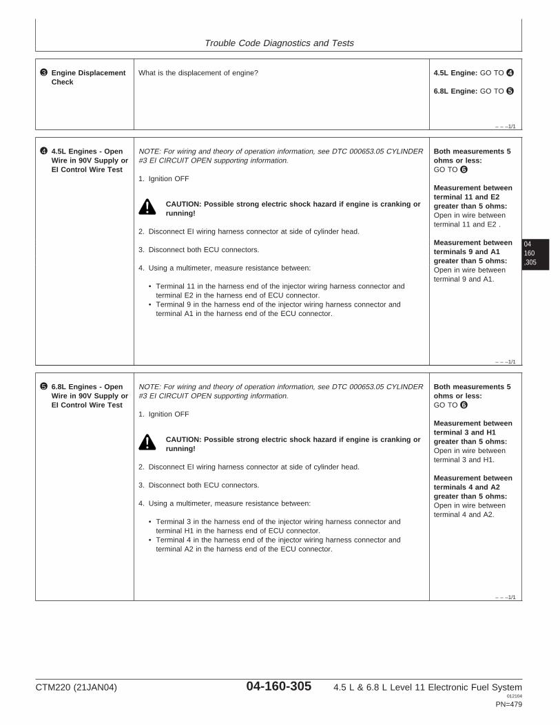
Trouble Code Diagnostics and Tests
– – –1/1
3 Engine DisplacementCheck
What is the displacement of engine? 4.5L Engine: GO TO 4
6.8L Engine: GO TO 5
04160,305
– – –1/1
4 4.5L Engines - OpenWire in 90V Supply orEI Control Wire Test
NOTE: For wiring and theory of operation information, see DTC 000653.05 CYLINDER#3 EI CIRCUIT OPEN supporting information.
1. Ignition OFF
CAUTION: Possible strong electric shock hazard if engine is cranking orrunning!
2. Disconnect EI wiring harness connector at side of cylinder head.
3. Disconnect both ECU connectors.
4. Using a multimeter, measure resistance between:
• Terminal 11 in the harness end of the injector wiring harness connector andterminal E2 in the harness end of ECU connector.
• Terminal 9 in the harness end of the injector wiring harness connector andterminal A1 in the harness end of the ECU connector.
Both measurements 5ohms or less:GO TO 6
Measurement betweenterminal 11 and E2greater than 5 ohms:Open in wire betweenterminal 11 and E2 .
Measurement betweenterminals 9 and A1greater than 5 ohms:Open in wire betweenterminal 9 and A1.
– – –1/1
5 6.8L Engines - OpenWire in 90V Supply orEI Control Wire Test
NOTE: For wiring and theory of operation information, see DTC 000653.05 CYLINDER#3 EI CIRCUIT OPEN supporting information.
1. Ignition OFF
CAUTION: Possible strong electric shock hazard if engine is cranking orrunning!
2. Disconnect EI wiring harness connector at side of cylinder head.
3. Disconnect both ECU connectors.
4. Using a multimeter, measure resistance between:
• Terminal 3 in the harness end of the injector wiring harness connector andterminal H1 in the harness end of ECU connector.
• Terminal 4 in the harness end of the injector wiring harness connector andterminal A2 in the harness end of the ECU connector.
Both measurements 5ohms or less:GO TO 6
Measurement betweenterminal 3 and H1greater than 5 ohms:Open in wire betweenterminal 3 and H1.
Measurement betweenterminals 4 and A2greater than 5 ohms:Open in wire betweenterminal 4 and A2.
CTM220 (21JAN04) 04-160-305 4.5 L & 6.8 L Level 11 Electronic Fuel System012104
PN=479

Trouble Code Diagnostics and Tests
04160,306
– – –1/1
6 Cylinder 3 EI Test NOTE: For wiring and theory of operation information, see DTC 000653.05 CYLINDER#3 EI CIRCUIT OPEN supporting information.
1. Remove rocker arm cover.
2. Disconnect electrical connections to cylinder 3 EI and a known good EI.
3. Using a multimeter measure resistance between:
• The two terminals on cylinder 3 EI.• The two terminals on the known good EI.
4. Compare the measurement between the two EIs.
NOTE: Because EI solenoid resistance varies with temperature, a comparison isused to compensate for the effects of temperature. Typically, injector resistanceshould be 0.35—0.55 ohms.
Difference betweenmeasurements 0.1ohms or less:GO TO 7
Difference betweenmeasurements greaterthan 0.1 ohms:Faulty cylinder 3 EIsolenoid.
– – –1/1
7 EI Harness inCylinder Head Test
NOTE: For wiring and theory of operation information, see DTC 000653.05 CYLINDER#3 EI CIRCUIT OPEN supporting information.
1. Ignition OFF
2. Cylinder 3 EI wires still disconnected from EI.
3. Disconnect EI wiring harness connector from side of cylinder head.
4. Using a multimeter, measure resistance between:
• One of the cylinder 3 EI harness eyelets and the corresponding terminal at theconnector on the rear of the cylinder head.
• The other cylinder 3 EI harness eyelet and the other corresponding terminal atthe connector on the side of the cylinder head.
Both measurements 2.0ohms or less:Faulty ECU connectionORFaulty EI wiring harnessconnectionORFaulty ECU
Either measurementsgreater than 2.0 ohms:Faulty EI harness inhead.
CTM220 (21JAN04) 04-160-306 4.5 L & 6.8 L Level 11 Electronic Fuel System012104
PN=480

Trouble Code Diagnostics and Tests
04160,307
CTM220 (21JAN04) 04-160-307 4.5 L & 6.8 L Level 11 Electronic Fuel System012104
PN=481

Trouble Code Diagnostics and Tests
04160,308
DPSG,RG40854,228 –19–01APR02–1/2
000653.06 — Cylinder #3 EI Circuit Shorted
EI Harness Connector
To Cylinder 2 EI
Cylinder 3 EI
4.5L Engine
Y1
Y2
Y3X3W3T3S3
X2W2T2S2
X1W1T1S1R1
R2
R3P3N3M3L3
P2N2M2L2
P1N1M1L1A1
A2
A3 B3 C3 D3 E3
B2 C2 D2 E2
B1 C1 D1 E1 F1
F2
F3 G3 H3 J3 K3
G2 H2 J2 K2
G1 H1 J1 K1
ECU HARNESS CONNECTOR
E2 A1
3
4
5
6
10
9
8
7
1
2
12
119
11
9
11
Cylinders 2 and 3 90 V Supply
Cylinder 3 Control
RG
1233
0–1
9–23
MA
Y02
EI Harness Connector
To Cylinders 1 & 2 EI's
Cylinder 3 EI
6.8L Engine
Y1
Y2
Y3X3W3T3S3
X2W2T2S2
X1W1T1S1R1
R2
R3P3N3M3L3
P2N2M2L2
P1N1M1L1A1
A2
A3 B3 C3 D3 E3
B2 C2 D2 E2
B1 C1 D1 E1 F1
F2
F3 G3 H3 J3 K3
G2 H2 J2 K2
G1 H1 J1 K1
ECU HARNESS CONNECTOR
H1 A2
3
4
5
6
10
9
8
7
1
2
12
114
3
4
3
Cylinders 1, 2 and 3 90 V Supply
Cylinder 3 Control
RG
1232
9–1
9–23
MA
Y02
NOTE: Wiring schematic shows OEM engineapplications only. For wiring information onother applications, see APPLICATIONSPECIFICATIONS in Section 06, Group 210 ofthis manual.
EI (Electronic Injector)
• The fuel in the 4.5L engine is delivered by 4 (one foreach cylinder) electronic injectors (EIs), and the 6.8Lengine is delivered by 6 EIs. The EIs are mounted inthey cylinder head, under the valve cover, so thatthey spray directly into the center of the cylinderbore. Each EI receives high pressure fuel from the
high pressure common rail. The ECU controls thestart of injection and the amount of fuel injected byturning the Two-Way Valve (TWV) in the EI valvehousing on and off which in turn opens and closesthe EI spill valve.
• On 4.5L engines, power is suppled to the EIs forcylinders 1 and 4 by a common wire, and to the EIsfor cylinders 2 and 3 by a common wire. On 6.8Lengines, power is supplied to the EIs for cylinders 1,2, and 3 by a common wire, and to the EIs forcylinders 4, 5, and 6 by a different common wire.The ECU energizes and de-energizes the TWV ofindividual EIs by closing and opening the individualEI ground circuits.
CTM220 (21JAN04) 04-160-308 4.5 L & 6.8 L Level 11 Electronic Fuel System012104
PN=482
Continued on next page

Trouble Code Diagnostics and Tests
DPSG,RG40854,228 –19–01APR02–2/2
DTC 000653.06 will set if:
• The ECU detects a short in the Cylinder #3 EIcircuit.
If DTC 000653.06 sets, the following will occur:
• Cylinder #3 EI will not fire.
04160,309
CTM220 (21JAN04) 04-160-309 4.5 L & 6.8 L Level 11 Electronic Fuel System012104
PN=483

Trouble Code Diagnostics and Tests
RG40854,000007A –19–01MAY02–1/1
000653.06 — Cylinder #3 EI Circuit Shorted
The ECU detects a short in the Cylinder #3 EI circuit.
04160,310
– – –1/1
000653.06 Cylinder #3 EI Circuit Shorted Diagnostic Procedure
IMPORTANT: If DTCs 000611.03, 000611.04, OR 000627.01 are active, repair those DTCs first .
– – –1/1
1 Connection Check IMPORTANT: Do not force probes into connector terminals or damage will result.Use JT07328 Connector Adapter Test Kit to make measurements in connectors.This will ensure that terminal damage does not occur.
NOTE: For wiring and theory of operation information, see DTC 000653.06 CYLINDER#3 EI CIRCUIT SHORTED supporting information.
Perform a preliminary inspection of ECU connectors and the injector harnessconnector (located at the side of the cylinder head) looking for dirty, damaged, orpoorly positioned terminals.
No faulty connection(s):GO TO 2
Faulty connection(s):Repair faultyconnection(s).
– – –1/1
2 Intermittent Fault Test NOTE: For wiring and theory of operation information, see DTC 000653.06 CYLINDER#3 EI CIRCUIT SHORTED supporting information.
1. Connect the DST or SERVICE ADVISOR. For instructions on connecting to theDST or SERVICE ADVISOR, see CONNECTING TO DIAGNOSTIC SCAN TOOL(DST) OR SERVICE ADVISOR earlier in this Group.
2. Ignition ON, engine OFF
3. Start the ECU diagnostic software
4. Make note of any DTCs, then clear all DTCs.
5. Ignition ON, engine running
6. Read DTCs using DST or SERVICE ADVISOR.
000653.06 reoccurs:GO TO 3
000653.06 does notreoccur:Problem is intermittent. Ifno other codes arepresent, seeINTERMITTENT FAULTDIAGNOSTICS earlier inthis Group.
SERVICE ADVISOR is a trademark of Deere & Company
CTM220 (21JAN04) 04-160-310 4.5 L & 6.8 L Level 11 Electronic Fuel System012104
PN=484

Trouble Code Diagnostics and Tests
– – –1/1
3 Engine DisplacementCheck
What is the displacement of engine? 4.5L Engine: GO TO 4
6.8L Engine: GO TO 5
04160,311
– – –1/1
4 4.5L Engines - Shortin EI Wiring HarnessTest
NOTE: For wiring and theory of operation information, see DTC 000653.06 CYLINDER#3 EI CIRCUIT SHORTED supporting information.
1. Ignition OFF
CAUTION: Possible strong electric shock hazard if engine is cranking orrunning!
2. Disconnect EI wiring harness connector at side of cylinder head.
3. Disconnect both ECU connectors.
4. Using a multimeter, measure resistance between terminal 11 in the harness end ofEI wiring connector and the following:
• Terminal 4 in the harness end of the EI wiring harness connector.• Terminal 9 in the harness end of the EI wiring harness connector.
Both measurementsgreater than 20000ohms:GO TO 6
Either measurementless than 20000 ohms:Short in ECU wiringharness.
– – –1/1
5 6.8L Engines - Shortin EI Wiring HarnessTest
NOTE: For wiring and theory of operation information, see DTC 000653.06 CYLINDER#3 EI CIRCUIT SHORTED supporting information.
1. Ignition OFF
CAUTION: Possible strong electric shock hazard if engine is cranking orrunning!
2. Disconnect EI wiring harness connector at side of cylinder head.
3. Disconnect both ECU connectors.
4. Using a multimeter, measure resistance between terminal 3 in the harness end ofEI wiring connector and the following:
• Terminal 4 in the harness end of the EI wiring harness connector.• Terminal 9 in the harness end of the EI wiring harness connector.
Both measurementsgreater than 20000ohms:GO TO 6
Either measurementless than 20000 ohms:Short in ECU wiringharness.
CTM220 (21JAN04) 04-160-311 4.5 L & 6.8 L Level 11 Electronic Fuel System012104
PN=485

Trouble Code Diagnostics and Tests
04160,312
– – –1/1
6 Cylinder 3 EI Test NOTE: For wiring and theory of operation information, see DTC 000653.06 CYLINDER#3 EI CIRCUIT SHORTED supporting information.
1. Remove rocker arm cover.
2. Disconnect electrical connections to cylinder 3 EI and a known good EI.
3. Using a multimeter, measure resistance between:
• The two terminals on cylinder 3 EI.• The two terminals on the known good EI.
4. Compare the measurements between the two EIs.
NOTE: Because EI resistance varies with temperature, a comparison is used tocompensate for the effects of temperature. Typical EI resistance should be 0.35—0.55 ohms.
Difference betweenmeasurements 0.1ohms or less:GO TO 7
Difference betweenmeasurements greaterthan 0.1 ohms:Faulty cylinder 3 EIsolenoid.
– – –1/1
7 EI Wiring Harness inCylinder Head Test
NOTE: For wiring and theory of operation information, see DTC 000653.06 CYLINDER#3 EI CIRCUIT SHORTED supporting information.
1. Ignition OFF
2. Keep cylinder 3 EI wires disconnected from EI.
3. Keep EI wiring harness connector at side of cylinder head disconnected.
4. Using a multimeter, measure resistance between:
• Both of the cylinder 3 EI harness eyelets.
Greater than 20000ohms:Faulty ECU connectionORFaulty EI wiring harnessconnectionORFaulty ECU
Less than 20000 ohms:Faulty EI wiring harness.
CTM220 (21JAN04) 04-160-312 4.5 L & 6.8 L Level 11 Electronic Fuel System012104
PN=486

Trouble Code Diagnostics and Tests
04160,313
CTM220 (21JAN04) 04-160-313 4.5 L & 6.8 L Level 11 Electronic Fuel System012104
PN=487

Trouble Code Diagnostics and Tests
04160,314
RG40854,000007B –19–01MAY02–1/2
000653.07 — Cylinder #3 EI Mechanical Failure
EI Harness Connector
To Cylinder 2 EI
Cylinder 3 EI
4.5L Engine
Y1
Y2
Y3X3W3T3S3
X2W2T2S2
X1W1T1S1R1
R2
R3P3N3M3L3
P2N2M2L2
P1N1M1L1A1
A2
A3 B3 C3 D3 E3
B2 C2 D2 E2
B1 C1 D1 E1 F1
F2
F3 G3 H3 J3 K3
G2 H2 J2 K2
G1 H1 J1 K1
ECU HARNESS CONNECTOR
E2 A1
3
4
5
6
10
9
8
7
1
2
12
119
11
9
11
Cylinders 2 and 3 90 V Supply
Cylinder 3 Control
RG
1233
0–1
9–23
MA
Y02
EI Harness Connector
To Cylinders 1 & 2 EI's
Cylinder 3 EI
6.8L Engine
Y1
Y2
Y3X3W3T3S3
X2W2T2S2
X1W1T1S1R1
R2
R3P3N3M3L3
P2N2M2L2
P1N1M1L1A1
A2
A3 B3 C3 D3 E3
B2 C2 D2 E2
B1 C1 D1 E1 F1
F2
F3 G3 H3 J3 K3
G2 H2 J2 K2
G1 H1 J1 K1
ECU HARNESS CONNECTOR
H1 A2
3
4
5
6
10
9
8
7
1
2
12
114
3
4
3
Cylinders 1, 2 and 3 90 V Supply
Cylinder 3 Control
RG
1232
9–1
9–23
MA
Y02
NOTE: Wiring schematic shows OEM engineapplications only. For wiring information onother applications, see APPLICATIONSPECIFICATIONS in Section 06, Group 210 ofthis manual.
EI (Electronic Injector)
• The fuel in the 4.5L engine is delivered by 4 (one foreach cylinder) electronic injectors (EIs), and the 6.8Lengine is delivered by 6 EIs. The EIs are mounted inthey cylinder head, under the valve cover, so thatthey spray directly into the center of the cylinderbore. Each EI receives high pressure fuel from the
high pressure common rail. The ECU controls thestart of injection and the amount of fuel injected byturning the Two-Way Valve (TWV) in the EI valvehousing on and off which in turn opens and closesthe EI spill valve.
• On 4.5L engines, power is suppled to the EIs forcylinders 1 and 4 by a common wire, and to the EIsfor cylinders 2 and 3 by a common wire. On 6.8Lengines, power is supplied to the EIs for cylinders 1,2, and 3 by a common wire, and to the EIs forcylinders 4, 5, and 6 by a different common wire.The ECU energizes and de-energizes the TWV ofindividual EIs by closing and opening the individualEI ground circuits.
CTM220 (21JAN04) 04-160-314 4.5 L & 6.8 L Level 11 Electronic Fuel System012104
PN=488
Continued on next page

Trouble Code Diagnostics and Tests
RG40854,000007B –19–01MAY02–2/2
DTC 000653.07 will set if:
• The fuel rail pressure does not drop at the injectionof fuel to EI #3.
If DTC 000653.07 sets, the following will occur:
• Engine will miss at EI #3.
04160,315
CTM220 (21JAN04) 04-160-315 4.5 L & 6.8 L Level 11 Electronic Fuel System012104
PN=489

Trouble Code Diagnostics and Tests
RG40854,000015F –19–23JUL02–1/1
000653.07 — Cylinder #3 EI Mechanical Failure
The fuel rail pressure does not drop at the injection offuel to EI #3.
04160,316
– – –1/1
000653.07 Cylinder #3 EI Mechanical Failure Diagnostic Procedure
– – –1/1
1 Connection Check IMPORTANT: Do not force probes into connector terminals or damage will result.Use JT07328 Connector Adapter Test Kit to make measurements in connectors.This will ensure that terminal damage does not occur.
NOTE: For wiring and theory of operation information, see DTC 000653.07 CYLINDER#3 EI MECHANICAL FAILURE supporting information.
Perform a preliminary inspection of ECU connectors and the injector harnessconnector (located at the side of the cylinder head) looking for dirty, damaged, orpoorly positioned terminals.
No faulty connection(s):GO TO 2
Faulty connection(s):Repair faultyconnection(s).
– – –1/1
2 EI Wiring HarnessCheck
NOTE: For wiring and theory of operation information, see DTC 000653.07 CYLINDER#3 EI MECHANICAL FAILURE supporting information.
1. Ignition OFF
CAUTION: Possible strong electrical shock hazard if engine is crankingor running.
2. Remove rocker arm cover with vent tube.
3. Verify all wiring harness eyelet connector retaining nuts are tightened tospecification.
SpecificationInjector Solenoid Wire Retaining Nut—Torque 2 N•m (1.5 lb-ft) (18 lb-in.).....................................................................................
4. Install rocker arm cover with vent tube. See INSTALL ROCKER ARM COVER inSection 02, Group 021 of CTM 104.
All retaining nut torquesat specification:GO TO 3
Retaining nut(s) loose:Tight retaining nut(s) tospecification and retest.
CTM220 (21JAN04) 04-160-316 4.5 L & 6.8 L Level 11 Electronic Fuel System012104
PN=490

Trouble Code Diagnostics and Tests
– – –1/1
3 EI Fuel LineRestriction Test
NOTE: For wiring and theory of operation information, see DTC 000653.07 CYLINDER#3 EI MECHANICAL FAILURE supporting information.
Check fuel lines for restrictions between High Pressure Common Rail (HPCR) and thefuel inlet at EI #3.
No restrictions found:GO TO 4
Restrictions found:Repair or replace fuel lineand retest
04160,317
– – –1/1
4 Flow Limiter Test NOTE: For wiring and theory of operation information, see DTC 000653.07 CYLINDER#3 EI MECHANICAL FAILURE supporting information.
1. Ignition ON, engine running under condition that sets code.
2. Using the ECU diagnostic software, verify that DTC 000653.07 is an ACTIVE code.
3. Listen to flow limiter that corresponds to EI #3 while turning ignition OFF.
NOTE: It is very difficult to distinguish the difference between EI #3 and the otherflow limiters clicking. Make sure EI #3 makes the click. It will take 5-10 seconds forthe ball to reseat.
Flow damper clicks:GO TO 5
Flow damper does notclick:Faulty flow limiter.Replace flow limiter andretest. See REMOVEAND INSTALL FLOWDAMPERS in Section 02,Group 090 earlier in thismanual.
– – –1/1
5 Side Feed TubeCheck
NOTE: For wiring and theory of operation information, see DTC 000653.07 CYLINDER#3 EI MECHANICAL FAILURE supporting information.
1. Ignition OFF
2. Disconnect the high pressure fuel delivery line for EI #3. Remove the side feed tuberetaining nut from the cylinder head.
3. Using a 1/2” hose grip pliers, remove the side feed tube from the cylinder head.
4. Inspect the side feed tube for nicks, burrs, or other damage.
5. Inspect side feed tube o-ring for damage.
6. When inspection is completed, reinstall inspected or install side feed tube andtighten side feed tube retaining nut to specification.
SpecificationSide Feed Tube Retaining Nut—Torque 35 N•m (25.5 lb-ft)............................................
7. Install the high pressure fuel delivery line to the side feed tube retaining nut.Tighten to specification:
SpecificationHigh Pressure Delivery Line Fitting—Torque 27 N•m (19.9 lb-ft).................................................................................................
Side feed tube ando-ring inspectionpasses:Faulty EIORFaulty ECU
Side feed tube ando-ring inspection fails:Replace side feed tubeand retest.
CTM220 (21JAN04) 04-160-317 4.5 L & 6.8 L Level 11 Electronic Fuel System012104
PN=491

Trouble Code Diagnostics and Tests
04160,318
RG40854,000007D –19–01MAY02–1/2
000654.05 — Cylinder #4 EI Circuit Open
EI Harness Connector
To Cylinder 1 EI
Cylinder 4 EI
4.5L Engine
Y1
Y2
Y3X3W3T3S3
X2W2T2S2
X1W1T1S1R1
R2
R3P3N3M3L3
P2N2M2L2
P1N1M1L1A1
A2
A3 B3 C3 D3 E3
B2 C2 D2 E2
B1 C1 D1 E1 F1
F2
F3 G3 H3 J3 K3
G2 H2 J2 K2
G1 H1 J1 K1
ECU HARNESS CONNECTOR
H1 A2
3
4
5
6
10
9
8
7
1
2
12
114
3
4
3
Cylinders 1 and 4 90 V Supply
Cylinder 4 Control
RG
1233
2–1
9–23
MA
Y02
Continued on next page
CTM220 (21JAN04) 04-160-318 4.5 L & 6.8 L Level 11 Electronic Fuel System012104
PN=492

Trouble Code Diagnostics and Tests
04160,319
RG40854,000007D –19–01MAY02–2/2
EI Harness Connector
To Cylinders 5 & 6 EI's
Cylinder 4 EI
6.8L Engine
Y1
Y2
Y3X3W3T3S3
X2W2T2S2
X1W1T1S1R1
R2
R3P3N3M3L3
P2N2M2L2
P1N1M1L1A1
A2
A3 B3 C3 D3 E3
B2 C2 D2 E2
B1 C1 D1 E1 F1
F2
F3 G3 H3 J3 K3
G2 H2 J2 K2
G1 H1 J1 K1
ECU HARNESS CONNECTOR
F2 A1
3
4
5
6
10
9
8
7
1
2
12
119
10
9
10
Cylinders 4, 5 and 6 90 V Supply
Cylinder 4 Control
RG
1233
1–1
9–23
MA
Y02
NOTE: Wiring schematic shows OEM engineapplications only. For wiring information onother applications, see APPLICATIONSPECIFICATIONS in Section 06, Group 210 ofthis manual.
EI (Electronic Injector)
• The fuel in the 4.5L engine is delivered by 4 (one foreach cylinder) electronic injectors (EIs), and the 6.8Lengine is delivered by 6 EIs. The EIs are mounted inthey cylinder head, under the valve cover, so thatthey spray directly into the center of the cylinderbore. Each EI receives high pressure fuel from thehigh pressure common rail. The ECU controls thestart of injection and the amount of fuel injected byturning the Two-Way Valve (TWV) in the EI valvehousing on and off which in turn opens and closesthe EI spill valve.
• On 4.5L engines, power is suppled to the EIs forcylinders 1 and 4 by a common wire, and to the EIsfor cylinders 2 and 3 by a common wire. On 6.8Lengines, power is supplied to the EIs for cylinders 1,2, and 3 by a common wire, and to the EIs forcylinders 4, 5, and 6 by a different common wire.The ECU energizes and de-energizes the TWV ofindividual EIs by closing and opening the individualEI ground circuits.
DTC 000654.05 will set if:
• The ECU detects an open in the Cylinder #4 EIcircuit.
If DTC 000654.05 sets, the following will occur:
• Cylinder #4 EI will not fire.
CTM220 (21JAN04) 04-160-319 4.5 L & 6.8 L Level 11 Electronic Fuel System012104
PN=493

Trouble Code Diagnostics and Tests
RG40854,0000083 –19–01MAY02–1/1
000654.05 — Cylinder #4 EI Circuit Open
– – –1/1
000654.05 Cylinder #4 EI Circuit Open Diagnostic Procedure
IMPORTANT: If DTCs 000611.03, 000611.04, or 000627.01 are active, repair those DTCs first.
04160,320
– – –1/1
1 Connection Check IMPORTANT: Do not force probes into connector terminals or damage will result.Use JT07328 Connector Adapter Test Kit to make measurements in connectors.This will ensure that terminal damage does not occur.
NOTE: For wiring and theory of operation information, see DTC 000654.05 CYLINDER#4 EI CIRCUIT OPEN supporting information.
Perform a preliminary inspection of ECU connectors and the injector harnessconnector (located at the side of the cylinder head) looking for dirty, damaged, orpoorly positioned terminals.
No faulty connection(s):GO TO 2
Faulty connection(s):Repair faultyconnection(s).
– – –1/1
2 Intermittent Fault Test NOTE: For wiring and theory of operation information, see DTC 000654.05 CYLINDER#4 EI CIRCUIT OPEN supporting information.
1. Connect the DST or SERVICE ADVISOR. For instructions on connecting to theDST or SERVICE ADVISOR, see CONNECTING TO DIAGNOSTIC SCAN TOOL(DST) OR SERVICE ADVISOR earlier in this Group.
2. Ignition ON, engine OFF
3. Start the ECU diagnostic software
4. Make note of any DTCs, then clear all DTCs.
5. Ignition ON, engine running
6. Read DTCs using DST or SERVICE ADVISOR.
000654.05 reoccurs:GO TO 3
000654.05 does notreoccur:Problem is intermittent. Ifno other codes arepresent, seeINTERMITTENT FAULTDIAGNOSTICS earlier inthis Group.
SERVICE ADVISOR is a trademark of Deere & Company
– – –1/1
3 Engine DisplacementCheck
What is the displacement of engine? 4.5L Engine: GO TO 4
6.8L Engine: GO TO 5
CTM220 (21JAN04) 04-160-320 4.5 L & 6.8 L Level 11 Electronic Fuel System012104
PN=494

Trouble Code Diagnostics and Tests
04160,321
– – –1/1
4 4.5L Engines - OpenWire in 90V Supply orEI Control Wire Test
NOTE: For wiring and theory of operation information, see DTC 000654.05 CYLINDER#4 EI CIRCUIT OPEN supporting information.
1. Ignition OFF
CAUTION: Possible strong electric shock hazard if engine is cranking orrunning!
2. Disconnect EI wiring harness connector at side of cylinder head.
3. Disconnect both ECU connectors.
4. Using a multimeter, measure resistance between:
• Terminal 3 in the harness end of the injector wiring harness connector andterminal H1 in the harness end of ECU connector.
• Terminal 4 in the harness end of the injector wiring harness connector andterminal A2 in the harness end of the ECU connector.
Both measurements 5ohms or less:GO TO 6
Measurement betweenterminals 3 and H1greater than 5 ohms:Open in wire betweenterminal 3 and H1.
Measurement betweenterminals 4 and A2greater than 5 ohms:Open in wire betweenterminal 4 and A2.
– – –1/1
5 6.8L Engines - OpenWire in 90V Supply orEI Control Wire Test
NOTE: For wiring and theory of operation information, see DTC 000654.05 CYLINDER#4 EI CIRCUIT OPEN supporting information.
1. Ignition OFF
CAUTION: Possible strong electric shock hazard if engine is cranking orrunning!
2. Disconnect EI wiring harness connector at side of cylinder head.
3. Disconnect both ECU connectors.
4. Using a multimeter, measure resistance between:
• Terminal 10 in the harness end of the injector wiring harness connector andterminal F2 in the harness end of ECU connector.
• Terminal 9 in the harness end of the injector wiring harness connector andterminal A1 in the harness end of the ECU connector.
Both measurements 5ohms or less:GO TO 6
Measurement betweenterminals 10 and F2greater than 5 ohms:Open in wire betweenterminal 10 and F2.
Measurement betweenterminals 9 and A1greater than 5 ohms:Open in wire betweenterminal 9 and A1.
CTM220 (21JAN04) 04-160-321 4.5 L & 6.8 L Level 11 Electronic Fuel System012104
PN=495

Trouble Code Diagnostics and Tests
04160,322
– – –1/1
6 Cylinder 4 EI Test NOTE: For wiring and theory of operation information, see DTC 000654.05 CYLINDER#4 EI CIRCUIT OPEN supporting information.
1. Remove rocker arm cover.
2. Disconnect electrical connections to cylinder 4 EI and a known good EI.
3. Using a multimeter measure resistance between:
• The two terminals on cylinder 4 EI.• The two terminals on the known good EI.
4. Compare the measurement between the two EIs.
NOTE: Because EI solenoid resistance varies with temperature, a comparison isused to compensate for the effects of temperature. Typically, injector resistanceshould be 0.35—0.55 ohms.
Difference betweenmeasurements 0.1ohms or less:GO TO 7
Difference betweenmeasurements greaterthan 0.1 ohms:Faulty cylinder 4 EIsolenoid.
– – –1/1
7 EI Harness inCylinder Head Test
NOTE: For wiring and theory of operation information, see DTC 000654.05 CYLINDER#4 EI CIRCUIT OPEN supporting information.
1. Ignition OFF
2. Cylinder 4 EI wires still disconnected from EI.
3. Disconnect EI wiring harness connector from side of cylinder head.
4. Using a multimeter, measure resistance between:
• One of the cylinder 4 EI harness eyelets and the corresponding terminal at theconnector on the rear of the cylinder head.
• The other cylinder 4 EI harness eyelet and the other corresponding terminal atthe connector on the side of the cylinder head.
Both measurements 2.0ohms or less:Faulty ECU connectionORFaulty EI wiring harnessconnectionORFaulty ECU
Either measurementsgreater than 2.0 ohms:Faulty EI harness inhead.
CTM220 (21JAN04) 04-160-322 4.5 L & 6.8 L Level 11 Electronic Fuel System012104
PN=496

Trouble Code Diagnostics and Tests
04160,323
CTM220 (21JAN04) 04-160-323 4.5 L & 6.8 L Level 11 Electronic Fuel System012104
PN=497

Trouble Code Diagnostics and Tests
04160,324
RG40854,0000080 –19–01MAY02–1/2
000654.06 — Cylinder #4 EI Circuit Shorted
EI Harness Connector
To Cylinder 1 EI
Cylinder 4 EI
4.5L Engine
Y1
Y2
Y3X3W3T3S3
X2W2T2S2
X1W1T1S1R1
R2
R3P3N3M3L3
P2N2M2L2
P1N1M1L1A1
A2
A3 B3 C3 D3 E3
B2 C2 D2 E2
B1 C1 D1 E1 F1
F2
F3 G3 H3 J3 K3
G2 H2 J2 K2
G1 H1 J1 K1
ECU HARNESS CONNECTOR
H1 A2
3
4
5
6
10
9
8
7
1
2
12
114
3
4
3
Cylinders 1 and 4 90 V Supply
Cylinder 4 Control
RG
1233
2–1
9–23
MA
Y02
Continued on next page
CTM220 (21JAN04) 04-160-324 4.5 L & 6.8 L Level 11 Electronic Fuel System012104
PN=498

Trouble Code Diagnostics and Tests
04160,325
RG40854,0000080 –19–01MAY02–2/2
EI Harness Connector
To Cylinders 5 & 6 EI's
Cylinder 4 EI
6.8L Engine
Y1
Y2
Y3X3W3T3S3
X2W2T2S2
X1W1T1S1R1
R2
R3P3N3M3L3
P2N2M2L2
P1N1M1L1A1
A2
A3 B3 C3 D3 E3
B2 C2 D2 E2
B1 C1 D1 E1 F1
F2
F3 G3 H3 J3 K3
G2 H2 J2 K2
G1 H1 J1 K1
ECU HARNESS CONNECTOR
F2 A1
3
4
5
6
10
9
8
7
1
2
12
119
10
9
10
Cylinders 4, 5 and 6 90 V Supply
Cylinder 4 Control
RG
1233
1–1
9–23
MA
Y02
NOTE: Wiring schematic shows OEM engineapplications only. For wiring information onother applications, see APPLICATIONSPECIFICATIONS in Section 06, Group 210 ofthis manual.
EI (Electronic Injector)
• The fuel in the 4.5L engine is delivered by 4 (one foreach cylinder) electronic injectors (EIs), and the 6.8Lengine is delivered by 6 EIs. The EIs are mounted inthey cylinder head, under the valve cover, so thatthey spray directly into the center of the cylinderbore. Each EI receives high pressure fuel from thehigh pressure common rail. The ECU controls thestart of injection and the amount of fuel injected byturning the Two-Way Valve (TWV) in the EI valvehousing on and off which in turn opens and closesthe EI spill valve.
• On 4.5L engines, power is suppled to the EIs forcylinders 1 and 4 by a common wire, and to the EIsfor cylinders 2 and 3 by a common wire. On 6.8Lengines, power is supplied to the EIs for cylinders 1,2, and 3 by a common wire, and to the EIs forcylinders 4, 5, and 6 by a different common wire.The ECU energizes and de-energizes the TWV ofindividual EIs by closing and opening the individualEI ground circuits.
DTC 000654.06 will set if:
• The ECU detects a short in the Cylinder #4 EIcircuit.
If DTC 000654.06 sets, the following will occur:
• Cylinder #4 EI will not fire.
CTM220 (21JAN04) 04-160-325 4.5 L & 6.8 L Level 11 Electronic Fuel System012104
PN=499

Trouble Code Diagnostics and Tests
RG40854,0000082 –19–01MAY02–1/1
000654.06 — Cylinder #4 EI Circuit Shorted
The ECU detects a short in the Cylinder #4 EI circuit.
04160,326
– – –1/1
000654.06 Cylinder #4 EI Circuit Shorted Diagnostic Procedure
IMPORTANT: If DTCs 000611.03, 000611.04, OR 000627.01 are active, repair those DTCs first .
– – –1/1
1 Connection Check IMPORTANT: Do not force probes into connector terminals or damage will result.Use JT07328 Connector Adapter Test Kit to make measurements in connectors.This will ensure that terminal damage does not occur.
NOTE: For wiring and theory of operation information, see DTC 000654.06 CYLINDER#4 EI CIRCUIT SHORTED supporting information.
Perform a preliminary inspection of ECU connectors and the injector harnessconnector (located at the side of the cylinder head) looking for dirty, damaged, orpoorly positioned terminals.
No faulty connection(s):GO TO 2
Faulty connection(s):Repair faultyconnection(s).
– – –1/1
2 Intermittent Fault Test NOTE: For wiring and theory of operation information, see DTC 000654.06 CYLINDER#4 EI CIRCUIT SHORTED supporting information.
1. Connect the DST or SERVICE ADVISOR. For instructions on connecting to theDST or SERVICE ADVISOR, see CONNECTING TO DIAGNOSTIC SCAN TOOL(DST) OR SERVICE ADVISOR earlier in this Group.
2. Ignition ON, engine OFF
3. Start the ECU diagnostic software
4. Make note of any DTCs, then clear all DTCs.
5. Ignition ON, engine running
6. Read DTCs using DST or SERVICE ADVISOR.
000654.06 reoccurs:GO TO 3
000654.06 does notreoccur:Problem is intermittent. Ifno other codes arepresent, seeINTERMITTENT FAULTDIAGNOSTICS earlier inthis Group.
SERVICE ADVISOR is a trademark of Deere & Company
CTM220 (21JAN04) 04-160-326 4.5 L & 6.8 L Level 11 Electronic Fuel System012104
PN=500

Trouble Code Diagnostics and Tests
– – –1/1
3 Engine DisplacementCheck
What is the displacement of engine? 4.5L Engine: GO TO 4
6.8L Engine: GO TO 5
04160,327
– – –1/1
4 4.5L Engines - Shortin EI Wiring HarnessTest
NOTE: For wiring and theory of operation information, see DTC 000654.06 CYLINDER#4 EI CIRCUIT SHORTED supporting information.
1. Ignition OFF
CAUTION: Possible strong electric shock hazard if engine is cranking orrunning!
2. Disconnect EI wiring harness connector at side of cylinder head.
3. Disconnect both ECU connectors.
4. Using a multimeter, measure resistance between terminal 3 in the harness end ofEI wiring connector and the following:
• Terminal 4 in the harness end of the EI wiring harness connector.• Terminal 9 in the harness end of the EI wiring harness connector.
Both measurementsgreater than 20000ohms:GO TO 6
Either measurementless than 20000 ohms:Short in ECU wiringharness.
– – –1/1
5 6.8L Engines - Shortin EI Wiring HarnessTest
NOTE: For wiring and theory of operation information, see DTC 000654.06 CYLINDER#4 EI CIRCUIT SHORTED supporting information.
1. Ignition OFF
CAUTION: Possible strong electric shock hazard if engine is cranking orrunning!
2. Disconnect EI wiring harness connector at side of cylinder head.
3. Disconnect both ECU connectors.
4. Using a multimeter, measure resistance between terminal 3 in the harness end ofEI wiring connector and the following:
• Terminal 4 in the harness end of the EI wiring harness connector.• Terminal 9 in the harness end of the EI wiring harness connector.
Both measurementsgreater than 20000ohms:GO TO 6
Either measurementless than 20000 ohms:Short in ECU wiringharness.
CTM220 (21JAN04) 04-160-327 4.5 L & 6.8 L Level 11 Electronic Fuel System012104
PN=501

Trouble Code Diagnostics and Tests
04160,328
– – –1/1
6 Cylinder 4 EI Test NOTE: For wiring and theory of operation information, see DTC 000654.06 CYLINDER#4 EI CIRCUIT SHORTED supporting information.
1. Remove rocker arm cover.
2. Disconnect electrical connections to cylinder 4 EI and a known good EI.
3. Using a multimeter, measure resistance between:
• The two terminals on cylinder 4 EI.• The two terminals on the known good EI.
4. Compare the measurements between the two EIs.
NOTE: Because EI resistance varies with temperature, a comparison is used tocompensate for the effects of temperature. Typical EI resistance should be 0.35—0.55 ohms.
Difference betweenmeasurements 0.1ohms or less:GO TO 7
Difference betweenmeasurements greaterthan 0.1 ohms:Faulty cylinder 4 EIsolenoid.
– – –1/1
7 EI Wiring Harness inCylinder Head Test
NOTE: For wiring and theory of operation information, see DTC 000654.06 CYLINDER#4 EI CIRCUIT SHORTED supporting information.
1. Ignition OFF
2. Keep cylinder 4 EI wires disconnected from EI.
3. Keep EI wiring harness connector at side of cylinder head disconnected.
4. Using a multimeter, measure resistance between:
• Both of the cylinder 4 EI harness eyelets.
Greater than 20000ohms:Faulty ECU connectionORFaulty EI wiring harnessconnectionORFaulty ECU
Less than 20000 ohms:Faulty EI wiring harness.
CTM220 (21JAN04) 04-160-328 4.5 L & 6.8 L Level 11 Electronic Fuel System012104
PN=502

Trouble Code Diagnostics and Tests
04160,329
CTM220 (21JAN04) 04-160-329 4.5 L & 6.8 L Level 11 Electronic Fuel System012104
PN=503

Trouble Code Diagnostics and Tests
04160,330
RG40854,0000084 –19–01MAY02–1/2
000654.07 — Cylinder #4 EI Mechanical Failure
EI Harness Connector
To Cylinder 1 EI
Cylinder 4 EI
4.5L Engine
Y1
Y2
Y3X3W3T3S3
X2W2T2S2
X1W1T1S1R1
R2
R3P3N3M3L3
P2N2M2L2
P1N1M1L1A1
A2
A3 B3 C3 D3 E3
B2 C2 D2 E2
B1 C1 D1 E1 F1
F2
F3 G3 H3 J3 K3
G2 H2 J2 K2
G1 H1 J1 K1
ECU HARNESS CONNECTOR
H1 A2
3
4
5
6
10
9
8
7
1
2
12
114
3
4
3
Cylinders 1 and 4 90 V Supply
Cylinder 4 Control
RG
1233
2–1
9–23
MA
Y02
Continued on next page
CTM220 (21JAN04) 04-160-330 4.5 L & 6.8 L Level 11 Electronic Fuel System012104
PN=504

Trouble Code Diagnostics and Tests
04160,331
RG40854,0000084 –19–01MAY02–2/2
EI Harness Connector
To Cylinders 5 & 6 EI's
Cylinder 4 EI
6.8L Engine
Y1
Y2
Y3X3W3T3S3
X2W2T2S2
X1W1T1S1R1
R2
R3P3N3M3L3
P2N2M2L2
P1N1M1L1A1
A2
A3 B3 C3 D3 E3
B2 C2 D2 E2
B1 C1 D1 E1 F1
F2
F3 G3 H3 J3 K3
G2 H2 J2 K2
G1 H1 J1 K1
ECU HARNESS CONNECTOR
F2 A1
3
4
5
6
10
9
8
7
1
2
12
119
10
9
10
Cylinders 4, 5 and 6 90 V Supply
Cylinder 4 Control
RG
1233
1–1
9–23
MA
Y02
NOTE: Wiring schematic shows OEM engineapplications only. For wiring information onother applications, see APPLICATIONSPECIFICATIONS in Section 06, Group 210 ofthis manual.
EI (Electronic Injector)
• The fuel in the 4.5L engine is delivered by 4 (one foreach cylinder) electronic injectors (EIs), and the 6.8Lengine is delivered by 6 EIs. The EIs are mounted inthey cylinder head, under the valve cover, so thatthey spray directly into the center of the cylinderbore. Each EI receives high pressure fuel from thehigh pressure common rail. The ECU controls thestart of injection and the amount of fuel injected byturning the Two-Way Valve (TWV) in the EI valvehousing on and off which in turn opens and closesthe EI spill valve.
• On 4.5L engines, power is suppled to the EIs forcylinders 1 and 4 by a common wire, and to the EIsfor cylinders 2 and 3 by a common wire. On 6.8Lengines, power is supplied to the EIs for cylinders 1,2, and 3 by a common wire, and to the EIs forcylinders 4, 5, and 6 by a different common wire.The ECU energizes and de-energizes the TWV ofindividual EIs by closing and opening the individualEI ground circuits.
DTC 000654.07 will set if:
• The fuel rail pressure does drop at the injection offuel to EI #4.
If DTC 000654.07 sets, the following will occur:
• Engine will miss at EI #4.
CTM220 (21JAN04) 04-160-331 4.5 L & 6.8 L Level 11 Electronic Fuel System012104
PN=505

Trouble Code Diagnostics and Tests
RG40854,0000160 –19–23JUL02–1/1
000654.07 — Cylinder #4 EI Mechanical Failure
The fuel rail pressure does drop at the injection of fuelto EI #4.
04160,332
– – –1/1
000654.07 Cylinder #4 EI Mechanical Failure Diagnostic Procedure
– – –1/1
1 Connection Check IMPORTANT: Do not force probes into connector terminals or damage will result.Use JT07328 Connector Adapter Test Kit to make measurements in connectors.This will ensure that terminal damage does not occur.
NOTE: For wiring and theory of operation information, see DTC 000654.07 CYLINDER#4 EI MECHANICAL FAILURE supporting information.
Perform a preliminary inspection of ECU connectors and the injector harnessconnector (located at the side of the cylinder head) looking for dirty, damaged, orpoorly positioned terminals.
No faulty connection(s):GO TO 2
Faulty connection(s):Repair faultyconnection(s).
– – –1/1
2 EI Wiring HarnessCheck
NOTE: For wiring and theory of operation information, see DTC 000654.07 CYLINDER#4 EI MECHANICAL FAILURE supporting information.
1. Ignition OFF
CAUTION: Possible strong electrical shock hazard if engine is crankingor running.
2. Remove rocker arm cover with vent tube.
3. Verify all wiring harness eyelet connector retaining nuts are tightened tospecification.
SpecificationInjector Solenoid Wire Retaining Nut—Torque 2 N•m (1.5 lb-ft) (18 lb-in.).....................................................................................
4. Install rocker arm cover with vent tube. See INSTALL ROCKER ARM COVER inSection 02, Group 021 of CTM 104.
All retaining nut torquesat specification:GO TO 3
Retaining nut(s) loose:Tight retaining nut(s) tospecification and retest.
CTM220 (21JAN04) 04-160-332 4.5 L & 6.8 L Level 11 Electronic Fuel System012104
PN=506

Trouble Code Diagnostics and Tests
– – –1/1
3 EI Fuel LineRestriction Test
NOTE: For wiring and theory of operation information, see DTC 000654.07 CYLINDER#4 EI MECHANICAL FAILURE supporting information.
Check fuel lines for restrictions between High Pressure Common Rail (HPCR) and thefuel inlet at EI #4.
No restrictions found:GO TO 4
Restrictions found:Repair or replace fuel lineand retest
04160,333
– – –1/1
4 Flow Limiter Test NOTE: For wiring and theory of operation information, see DTC 000654.07 CYLINDER#4 EI MECHANICAL FAILURE supporting information.
1. Ignition ON, engine running under condition that sets code.
2. Using the ECU diagnostic software, verify that DTC 000654.07 is an ACTIVE code.
3. Listen to flow limiter that corresponds to EI #4 while turning ignition OFF.
NOTE: It is very difficult to distinguish the difference between EI #4 and the otherflow limiters clicking. Make sure EI #4 makes the click. It will take 5-10 seconds forthe ball to reseat.
Flow damper clicks:GO TO 5
Flow damper does notclick:Faulty flow limiter.Replace flow limiter andretest. See REMOVEAND INSTALL FLOWDAMPERS in Section 02,Group 090 earlier in thismanual.
– – –1/1
5 Side Feed TubeCheck
NOTE: For wiring and theory of operation information, see DTC 000654.07 CYLINDER#4 EI MECHANICAL FAILURE supporting information.
1. Ignition OFF
2. Disconnect the high pressure fuel delivery line for EI #4. Remove the side feed tuberetaining nut from the cylinder head.
3. Using a 1/2” hose grip pliers, remove the side feed tube from the cylinder head.
4. Inspect the side feed tube for nicks, burrs, or other damage.
5. Inspect side feed tube o-ring for damage.
6. When inspection is completed, reinstall inspected or install side feed tube andtighten side feed tube retaining nut to specification.
SpecificationSide Feed Tube Retaining Nut—Torque 35 N•m (25.5 lb-ft)............................................
7. Install the high pressure fuel delivery line to the side feed tube retaining nut.Tighten to specification:
SpecificationHigh Pressure Delivery Line Fitting—Torque 27 N•m (19.9 lb-ft).................................................................................................
Side feed tube ando-ring inspectionpasses:Faulty EIORFaulty ECU
Side feed tube ando-ring inspection fails:Replace side feed tubeand retest.
CTM220 (21JAN04) 04-160-333 4.5 L & 6.8 L Level 11 Electronic Fuel System012104
PN=507

Trouble Code Diagnostics and Tests
04160,334
RG40854,0000087 –19–01MAY02–1/1
000655.05 — Cylinder #5 EI Circuit Open
EI Harness Connector
To Cylinders 4 & 6 EI's
Cylinder 5 EI
6.8L Engine
Y1
Y2
Y3X3W3T3S3
X2W2T2S2
X1W1T1S1R1
R2
R3P3N3M3L3
P2N2M2L2
P1N1M1L1A1
A2
A3 B3 C3 D3 E3
B2 C2 D2 E2
B1 C1 D1 E1 F1
F2
F3 G3 H3 J3 K3
G2 H2 J2 K2
G1 H1 J1 K1
ECU HARNESS CONNECTOR
E2 A1
3
4
5
6
10
9
8
7
1
2
12
119
11
9
11
Cylinders 4, 5 and 6 90 V Supply
Cylinder 5 Control
RG
1233
3–1
9–23
MA
Y02
NOTE: Wiring schematic shows OEM engineapplications only. For wiring information onother applications, see APPLICATIONSPECIFICATIONS in Section 06, Group 210 ofthis manual.
EI (Electronic Injector)
• The fuel in the 4.5L engine is delivered by 4 (one foreach cylinder) electronic injectors (EIs), and the 6.8Lengine is delivered by 6 EIs. The EIs are mounted inthey cylinder head, under the valve cover, so thatthey spray directly into the center of the cylinderbore. Each EI receives high pressure fuel from thehigh pressure common rail. The ECU controls thestart of injection and the amount of fuel injected byturning the Two-Way Valve (TWV) in the EI valvehousing on and off which in turn opens and closesthe EI spill valve.
• On 4.5L engines, power is suppled to the EIs forcylinders 1 and 4 by a common wire, and to the EIsfor cylinders 2 and 3 by a common wire. On 6.8Lengines, power is supplied to the EIs for cylinders 1,2, and 3 by a common wire, and to the EIs forcylinders 4, 5, and 6 by a different common wire.The ECU energizes and de-energizes the TWV ofindividual EIs by closing and opening the individualEI ground circuits.
DTC 000655.05 will set if:
• The ECU detects an open in the Cylinder #5 EIcircuit.
If DTC 000655.05 sets, the following will occur:
• Cylinder #5 EI will not fire.
CTM220 (21JAN04) 04-160-334 4.5 L & 6.8 L Level 11 Electronic Fuel System012104
PN=508

Trouble Code Diagnostics and Tests
RG40854,0000088 –19–01MAY02–1/1
000655.05 — Cylinder #5 EI Circuit Open
The ECU detects an open in the Cylinder #5 EI circuit.
04160,335
– – –1/1
000655.05 Cylinder #5 EI Circuit Open Diagnostic Procedure
IMPORTANT: If DTCs 000611.03, 000611.04, or 000627.01 are active, repair those DTCs first.
– – –1/1
1 Connection Check IMPORTANT: Do not force probes into connector terminals or damage will result.Use JT07328 Connector Adapter Test Kit to make measurements in connectors.This will ensure that terminal damage does not occur.
NOTE: For wiring and theory of operation information, see DTC 000655.05 CYLINDER#5 EI CIRCUIT OPEN supporting information.
Perform a preliminary inspection of ECU connectors and the injector harnessconnector (located at the side of the cylinder head) looking for dirty, damaged, orpoorly positioned terminals.
No faulty connection(s):GO TO 2
Faulty connection(s):Repair faultyconnection(s).
– – –1/1
2 Intermittent Fault Test NOTE: For wiring and theory of operation information, see DTC 000655.05 CYLINDER#5 EI CIRCUIT OPEN supporting information.
1. Connect the DST or SERVICE ADVISOR. For instructions on connecting to theDST or SERVICE ADVISOR, CONNECTING TO DIAGNOSTIC SCAN TOOL(DST) OR SERVICE ADVISOR earlier in this Group.
2. Ignition ON, engine OFF
3. Start the ECU diagnostic software
4. Make note of any DTCs, then clear all DTCs.
5. Ignition ON, engine running
6. Read DTCs using DST or SERVICE ADVISOR.
000655.05 reoccurs:GO TO 3
000655.05 does notreoccur:Problem is intermittent. Ifno other codes arepresent, seeINTERMITTENT FAULTDIAGNOSTICS earlier inthis Group.
SERVICE ADVISOR is a trademark of Deere & Company
CTM220 (21JAN04) 04-160-335 4.5 L & 6.8 L Level 11 Electronic Fuel System012104
PN=509

Trouble Code Diagnostics and Tests
04160,336
– – –1/1
3 Open Wire in 90VSupply or EI ControlWire Test
NOTE: For wiring and theory of operation information, see DTC 000655.05 CYLINDER#5 EI CIRCUIT OPEN supporting information.
1. Ignition OFF
CAUTION: Possible strong electric shock hazard if engine is cranking orrunning!
2. Disconnect EI wiring harness connector at side of cylinder head.
3. Disconnect both 30-way ECU connectors.
4. Using a multimeter, measure resistance between:
• Terminal 11 in the harness end of the injector wiring harness connector andterminal E2 in the harness end of ECU connector.
• Terminal 9 in the harness end of the injector wiring harness connector andterminal A1 in the harness end of the ECU connector.
Both measurements 5ohms or less:GO TO 4
Measurement betweenterminals 11 and E2greater than 5 ohms:Open in wire betweenterminal 11 and E2.
Measurement betweenterminals 9 and A1greater than 5 ohms:Open in wire betweenterminal 9 and A1.
– – –1/1
4 Cylinder 5 EI Test NOTE: For wiring and theory of operation information, see DTC 000655.05 CYLINDER#5 EI CIRCUIT OPEN supporting information.
1. Remove rocker arm cover.
2. Disconnect electrical connections to cylinder 5 EI and a known good EI.
3. Using a multimeter measure resistance between:
• The two terminals on cylinder 5 EI.• The two terminals on the known good EI.
4. Compare the measurement between the two EIs.
NOTE: Because EI solenoid resistance varies with temperature, a comparison isused to compensate for the effects of temperature. Typically, injector resistanceshould be 0.35—0.55 ohms.
Difference betweenmeasurements 0.1ohms or less:GO TO 5
Difference betweenmeasurements greaterthan 0.1 ohms:Faulty cylinder 5 EIsolenoid.
CTM220 (21JAN04) 04-160-336 4.5 L & 6.8 L Level 11 Electronic Fuel System012104
PN=510

Trouble Code Diagnostics and Tests
04160,337
– – –1/1
5 EI Harness inCylinder Head Test
NOTE: For wiring and theory of operation information, see DTC 000655.05 CYLINDER#5 EI CIRCUIT OPEN supporting information.
1. Ignition OFF
2. Cylinder 5 EI wires still disconnected from EI.
3. Disconnect EI wiring harness connector from side of cylinder head.
4. Using a multimeter, measure resistance between:
• One of the cylinder 5 EI harness eyelet and the corresponding terminal at theconnector on the rear of the cylinder head
• The other cylinder 5 EI harness eyelet and the other corresponding terminal atthe connector on the side of the cylinder head.
Both measurements 2.0ohms or less:Faulty ECU connectionORFaulty EI wiring harnessconnectionORFaulty ECU
Either measurementsgreater than 2.0 ohms:Faulty EI harness inhead.
CTM220 (21JAN04) 04-160-337 4.5 L & 6.8 L Level 11 Electronic Fuel System012104
PN=511

Trouble Code Diagnostics and Tests
04160,338
RG40854,0000089 –19–01MAY02–1/1
000655.06 — Cylinder #5 EI Circuit Shorted
EI Harness Connector
To Cylinders 4 & 6 EI's
Cylinder 5 EI
6.8L Engine
Y1
Y2
Y3X3W3T3S3
X2W2T2S2
X1W1T1S1R1
R2
R3P3N3M3L3
P2N2M2L2
P1N1M1L1A1
A2
A3 B3 C3 D3 E3
B2 C2 D2 E2
B1 C1 D1 E1 F1
F2
F3 G3 H3 J3 K3
G2 H2 J2 K2
G1 H1 J1 K1
ECU HARNESS CONNECTOR
E2 A1
3
4
5
6
10
9
8
7
1
2
12
119
11
9
11
Cylinders 4, 5 and 6 90 V Supply
Cylinder 5 Control
RG
1233
3–1
9–23
MA
Y02
NOTE: Wiring schematic shows OEM engineapplications only. For wiring information onother applications, see APPLICATIONSPECIFICATIONS in Section 06, Group 210 ofthis manual.
EI (Electronic Injector)
• The fuel in the 4.5L engine is delivered by 4 (one foreach cylinder) electronic injectors (EIs), and the 6.8Lengine is delivered by 6 EIs. The EIs are mounted inthey cylinder head, under the valve cover, so thatthey spray directly into the center of the cylinderbore. Each EI receives high pressure fuel from thehigh pressure common rail. The ECU controls thestart of injection and the amount of fuel injected byturning the Two-Way Valve (TWV) in the EI valvehousing on and off which in turn opens and closesthe EI spill valve.
• On 4.5L engines, power is suppled to the EIs forcylinders 1 and 4 by a common wire, and to the EIsfor cylinders 2 and 3 by a common wire. On 6.8Lengines, power is supplied to the EIs for cylinders 1,2, and 3 by a common wire, and to the EIs forcylinders 4, 5, and 6 by a different common wire.The ECU energizes and de-energizes the TWV ofindividual EIs by closing and opening the individualEI ground circuits.
DTC 000655.06 will set if:
• The ECU detects an open in the Cylinder #5 EIcircuit.
If DTC 000655.06 sets, the following will occur:
• Cylinder #5 EI will not fire.
CTM220 (21JAN04) 04-160-338 4.5 L & 6.8 L Level 11 Electronic Fuel System012104
PN=512

Trouble Code Diagnostics and Tests
RG40854,000008A –19–01MAY02–1/1
000655.06 — Cylinder #5 EI Circuit Shorted
The ECU detects an open in the Cylinder #5 EI circuit.
04160,339
– – –1/1
000655.06 Cylinder #5 EI Circuit Shorted Diagnostic Procedure
IMPORTANT: If DTCs 000611.03, 000611.04, OR 000627.01 are active, repair those DTCs first .
– – –1/1
1 Connection Check IMPORTANT: Do not force probes into connector terminals or damage will result.Use JT07328 Connector Adapter Test Kit to make measurements in connectors.This will ensure that terminal damage does not occur.
NOTE: For wiring and theory of operation information, see DTC 000655.06 CYLINDER#5 EI CIRCUIT SHORTED supporting information.
Perform a preliminary inspection of ECU connectors and the injector harnessconnector (located at the side of the cylinder head) looking for dirty, damaged, orpoorly positioned terminals.
No faulty connection(s):GO TO 2
Faulty connection(s):Repair faultyconnection(s).
– – –1/1
2 Intermittent Fault Test NOTE: For wiring and theory of operation information, see DTC 000655.06 CYLINDER#5 EI CIRCUIT SHORTED supporting information.
1. Connect the DST or SERVICE ADVISOR. For instructions on connecting to theDST or SERVICE ADVISOR, see CONNECTING TO DIAGNOSTIC SCAN TOOL(DST) OR SERVICE ADVISOR earlier in this Group.
2. Ignition ON, engine OFF
3. Start the ECU diagnostic software
4. Make note of any DTCs, then clear all DTCs.
5. Ignition ON, engine running
6. Read DTCs using DST or SERVICE ADVISOR.
000655.06 reoccurs:GO TO 3
000655.06 does notreoccur:Problem is intermittent. Ifno other codes arepresent, see earlier in thisGroup.
SERVICE ADVISOR is a trademark of Deere & Company
CTM220 (21JAN04) 04-160-339 4.5 L & 6.8 L Level 11 Electronic Fuel System012104
PN=513

Trouble Code Diagnostics and Tests
04160,340
– – –1/1
3 Short in EI WiringHarness Test
NOTE: For wiring and theory of operation information, see DTC 000655.06 CYLINDER#5 EI CIRCUIT SHORTED supporting information.
1. Ignition OFF
CAUTION: Possible strong electric shock hazard if engine is cranking orrunning!
2. Disconnect EI wiring harness connector at side of cylinder head.
3. Disconnect both ECU connectors.
4. Using a multimeter, measure resistance between terminal 11 in the harness end ofEI wiring connector and the following:
• Terminal 4 in the harness end of the EI wiring harness connector.• Terminal 9 in the harness end of the EI wiring harness connector.
Both measurementsgreater than 20000ohms:GO TO 4
Either measurementless than 20000 ohms:Short in ECU wiringharness.
– – –1/1
4 Cylinder 5 EI Test NOTE: For wiring and theory of operation information, see DTC 000655.06 CYLINDER#5 EI CIRCUIT SHORTED supporting information.
1. Remove rocker arm cover.
2. Disconnect electrical connections to cylinder 5 EI and a known good EI.
3. Using a multimeter, measure resistance between:
• The two terminals on cylinder 5 EI.• The two terminals on the known good EI.
4. Compare the measurements between the two EIs.
NOTE: Because EI resistance varies with temperature, a comparison is used tocompensate for the effects of temperature. Typical EI resistance should be 0.35—0.55 ohms.
Difference betweenmeasurements 0.1ohms or less:GO TO 5
Difference betweenmeasurements greaterthan 0.1 ohms:Faulty cylinder 5 injectorsolenoid.
– – –1/1
5 EI Wiring Harness inCylinder Head Test
NOTE: For wiring and theory of operation information, see DTC 000655.06 CYLINDER#5 EI CIRCUIT SHORTED supporting information.
1. Ignition OFF
2. Keep cylinder 5 EI wires disconnected from EI.
3. Keep EI wiring harness connector at side of cylinder head disconnected.
4. Using a multimeter, measure resistance between:
• Both of the cylinder 5 EI harness eyelet’s.
Greater than 20000ohms:Faulty ECU connectionORFaulty EI wiring harnessconnectionORFaulty ECU
Less than 20000 ohms:Faulty EI wiring harness.
CTM220 (21JAN04) 04-160-340 4.5 L & 6.8 L Level 11 Electronic Fuel System012104
PN=514

Trouble Code Diagnostics and Tests
04160,341
CTM220 (21JAN04) 04-160-341 4.5 L & 6.8 L Level 11 Electronic Fuel System012104
PN=515

Trouble Code Diagnostics and Tests
04160,342
RG40854,000008B –19–01MAY02–1/1
000655.07 — Cylinder #5 EI Mechanical Failure
EI Harness Connector
To Cylinders 4 & 6 EI's
Cylinder 5 EI
6.8L Engine
Y1
Y2
Y3X3W3T3S3
X2W2T2S2
X1W1T1S1R1
R2
R3P3N3M3L3
P2N2M2L2
P1N1M1L1A1
A2
A3 B3 C3 D3 E3
B2 C2 D2 E2
B1 C1 D1 E1 F1
F2
F3 G3 H3 J3 K3
G2 H2 J2 K2
G1 H1 J1 K1
ECU HARNESS CONNECTOR
E2 A1
3
4
5
6
10
9
8
7
1
2
12
119
11
9
11
Cylinders 4, 5 and 6 90 V Supply
Cylinder 5 Control
RG
1233
3–1
9–23
MA
Y02
NOTE: Wiring schematic shows OEM engineapplications only. For wiring information onother applications, see APPLICATIONSPECIFICATIONS in Section 06, Group 210 ofthis manual.
EI (Electronic Injector)
• The fuel in the 4.5L engine is delivered by 4 (one foreach cylinder) electronic injectors (EIs), and the 6.8Lengine is delivered by 6 EIs. The EIs are mounted inthey cylinder head, under the valve cover, so thatthey spray directly into the center of the cylinderbore. Each EI receives high pressure fuel from thehigh pressure common rail. The ECU controls thestart of injection and the amount of fuel injected byturning the Two-Way Valve (TWV) in the EI valvehousing on and off which in turn opens and closesthe EI spill valve.
• On 4.5L engines, power is suppled to the EIs forcylinders 1 and 4 by a common wire, and to the EIsfor cylinders 2 and 3 by a common wire. On 6.8Lengines, power is supplied to the EIs for cylinders 1,2, and 3 by a common wire, and to the EIs forcylinders 4, 5, and 6 by a different common wire.The ECU energizes and de-energizes the TWV ofindividual EIs by closing and opening the individualEI ground circuits.
DTC 000655.07 will set if:
• The fuel rail pressure does not drop at the injectionof fuel to EI #5.
If DTC 000655.07 sets, the following will occur:
• Engine will miss at EI #5.
CTM220 (21JAN04) 04-160-342 4.5 L & 6.8 L Level 11 Electronic Fuel System012104
PN=516
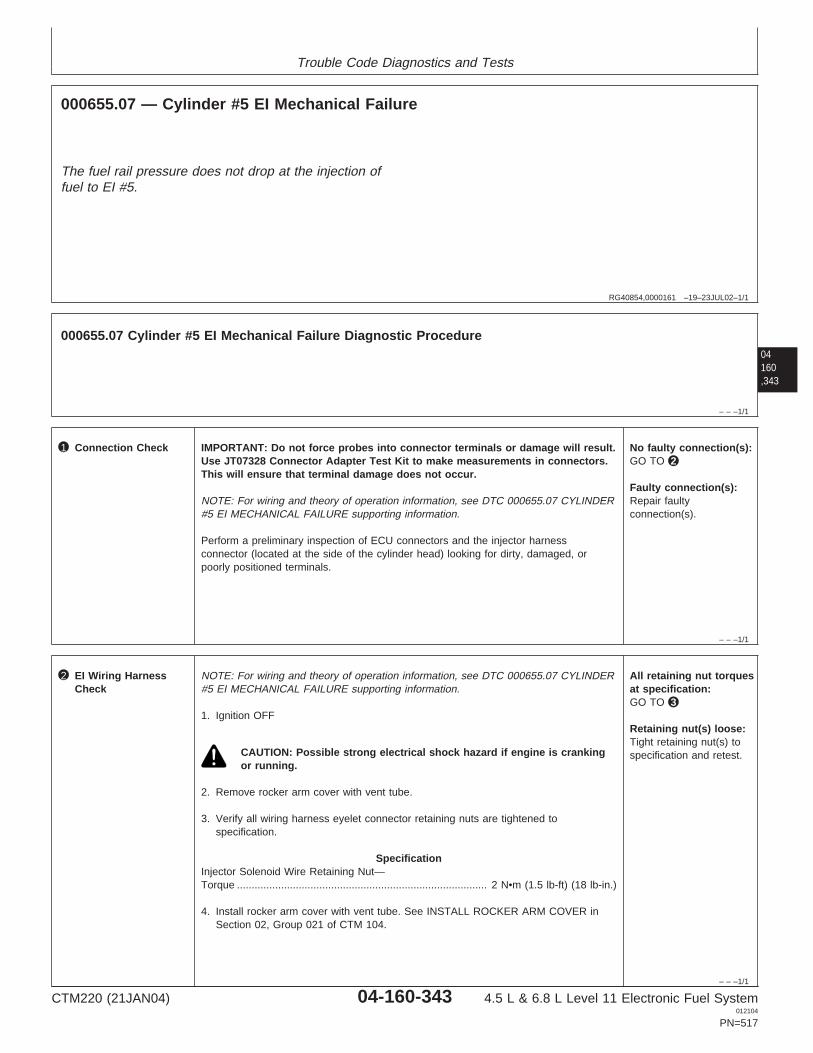
Trouble Code Diagnostics and Tests
RG40854,0000161 –19–23JUL02–1/1
000655.07 — Cylinder #5 EI Mechanical Failure
The fuel rail pressure does not drop at the injection offuel to EI #5.
04160,343
– – –1/1
000655.07 Cylinder #5 EI Mechanical Failure Diagnostic Procedure
– – –1/1
1 Connection Check IMPORTANT: Do not force probes into connector terminals or damage will result.Use JT07328 Connector Adapter Test Kit to make measurements in connectors.This will ensure that terminal damage does not occur.
NOTE: For wiring and theory of operation information, see DTC 000655.07 CYLINDER#5 EI MECHANICAL FAILURE supporting information.
Perform a preliminary inspection of ECU connectors and the injector harnessconnector (located at the side of the cylinder head) looking for dirty, damaged, orpoorly positioned terminals.
No faulty connection(s):GO TO 2
Faulty connection(s):Repair faultyconnection(s).
– – –1/1
2 EI Wiring HarnessCheck
NOTE: For wiring and theory of operation information, see DTC 000655.07 CYLINDER#5 EI MECHANICAL FAILURE supporting information.
1. Ignition OFF
CAUTION: Possible strong electrical shock hazard if engine is crankingor running.
2. Remove rocker arm cover with vent tube.
3. Verify all wiring harness eyelet connector retaining nuts are tightened tospecification.
SpecificationInjector Solenoid Wire Retaining Nut—Torque 2 N•m (1.5 lb-ft) (18 lb-in.).....................................................................................
4. Install rocker arm cover with vent tube. See INSTALL ROCKER ARM COVER inSection 02, Group 021 of CTM 104.
All retaining nut torquesat specification:GO TO 3
Retaining nut(s) loose:Tight retaining nut(s) tospecification and retest.
CTM220 (21JAN04) 04-160-343 4.5 L & 6.8 L Level 11 Electronic Fuel System012104
PN=517

Trouble Code Diagnostics and Tests
– – –1/1
3 EI Fuel LineRestriction Test
NOTE: For wiring and theory of operation information, see DTC 000655.07 CYLINDER#5 EI MECHANICAL FAILURE supporting information.
Check fuel lines for restrictions between High Pressure Common Rail (HPCR) and thefuel inlet at EI #5.
No restrictions found:GO TO 4
Restrictions found:Repair or replace fuel lineand retest
04160,344
– – –1/1
4 Flow Limiter Test NOTE: For wiring and theory of operation information, see DTC 000655.07 CYLINDER#5 EI MECHANICAL FAILURE supporting information.
1. Ignition ON, engine running under condition that sets code.
2. Using the ECU diagnostic software, verify that DTC 000655.07 is an ACTIVE code.
3. Listen to flow limiter that corresponds to EI #5 while turning ignition OFF.
NOTE: It is very difficult to distinguish the difference between EI #5 and the otherflow limiters clicking. Make sure EI #5 makes the click. It will take 5-10 seconds forthe ball to reseat.
Flow damper clicks:GO TO 5
Flow damper does notclick:Faulty flow limiter.Replace flow limiter andretest. See REMOVEAND INSTALL FLOWDAMPERS in Section 02,Group 090 earlier in thismanual.
– – –1/1
5 Side Feed TubeCheck
NOTE: For wiring and theory of operation information, see DTC 000655.07 CYLINDER#5 EI MECHANICAL FAILURE supporting information.
1. Ignition OFF
2. Disconnect the high pressure fuel delivery line for EI #5. Remove the side feed tuberetaining nut from the cylinder head.
3. Using a 1/2” hose grip pliers, remove the side feed tube from the cylinder head.
4. Inspect the side feed tube for nicks, burrs, or other damage.
5. Inspect side feed tube o-ring for damage.
6. When inspection is completed, reinstall inspected or install side feed tube andtighten side feed tube retaining nut to specification.
SpecificationSide Feed Tube Retaining Nut—Torque 35 N•m (25.5 lb-ft)............................................
7. Install the high pressure fuel delivery line to the side feed tube retaining nut.Tighten to specification:
SpecificationHigh Pressure Delivery Line Fitting—Torque 27 N•m (19.9 lb-ft).................................................................................................
Side feed tube ando-ring inspectionpasses:Faulty EIORFaulty ECU
Side feed tube ando-ring inspection fails:Replace side feed tubeand retest.
CTM220 (21JAN04) 04-160-344 4.5 L & 6.8 L Level 11 Electronic Fuel System012104
PN=518

Trouble Code Diagnostics and Tests
04160,345
CTM220 (21JAN04) 04-160-345 4.5 L & 6.8 L Level 11 Electronic Fuel System012104
PN=519

Trouble Code Diagnostics and Tests
04160,346
RG40854,000008D –19–01MAY02–1/1
000656.05 — Cylinder #6 EI Circuit Open
EI Harness Connector
To Cylinders 4 & 5 EI's
Cylinder 6 EI
6.8L Engine
Y1
Y2
Y3X3W3T3S3
X2W2T2S2
X1W1T1S1R1
R2
R3P3N3M3L3
P2N2M2L2
P1N1M1L1A1
A2
A3 B3 C3 D3 E3
B2 C2 D2 E2
B1 C1 D1 E1 F1
F2
F3 G3 H3 J3 K3
G2 H2 J2 K2
G1 H1 J1 K1
ECU HARNESS CONNECTOR
G1 A1
3
4
5
6
10
9
8
7
1
2
12
119
12
9
12
Cylinders 4, 5 and 6 90 V Supply
Cylinder 6 Control
RG
1233
4–1
9–23
MA
Y02
NOTE: Wiring schematic shows OEM engineapplications only. For wiring information onother applications, see APPLICATIONSPECIFICATIONS in Section 06, Group 210 ofthis manual.
EI (Electronic Injector)
• The fuel in the 4.5L engine is delivered by 4 (one foreach cylinder) electronic injectors (EIs), and the 6.8Lengine is delivered by 6 EIs. The EIs are mounted inthey cylinder head, under the valve cover, so thatthey spray directly into the center of the cylinderbore. Each EI receives high pressure fuel from thehigh pressure common rail. The ECU controls thestart of injection and the amount of fuel injected byturning the Two-Way Valve (TWV) in the EI valvehousing on and off which in turn opens and closesthe EI spill valve.
• On 4.5L engines, power is suppled to the EIs forcylinders 1 and 4 by a common wire, and to the EIsfor cylinders 2 and 3 by a common wire. On 6.8Lengines, power is supplied to the EIs for cylinders 1,2, and 3 by a common wire, and to the EIs forcylinders 4, 5, and 6 by a different common wire.The ECU energizes and de-energizes the TWV ofindividual EIs by closing and opening the individualEI ground circuits.
DTC 000656.05 will set if:
• The ECU detects an open in the Cylinder #6 EIcircuit.
If DTC 000656.05 sets, the following will occur:
• Cylinder #6 EI will not fire.
CTM220 (21JAN04) 04-160-346 4.5 L & 6.8 L Level 11 Electronic Fuel System012104
PN=520

Trouble Code Diagnostics and Tests
RG40854,000008E –19–01MAY02–1/1
000656.05 — Cylinder #6 EI Circuit Open
The ECU detects an open in the Cylinder #6 EI circuit.
04160,347
– – –1/1
000656.05 Cylinder #6 EI Circuit Open Diagnostic Procedure
IMPORTANT: If DTCs 000611.03, 000611.04, or 000627.01 are active, repair those DTCs first.
– – –1/1
1 Connection Check IMPORTANT: Do not force probes into connector terminals or damage will result.Use JT07328 Connector Adapter Test Kit to make measurements in connectors.This will ensure that terminal damage does not occur.
NOTE: For wiring and theory of operation information, see DTC 000656.05 CYLINDER#6 EI CIRCUIT OPEN supporting information.
Perform a preliminary inspection of ECU connectors and the injector harnessconnector (located at the side of the cylinder head) looking for dirty, damaged, orpoorly positioned terminals.
No faulty connection(s):GO TO 2
Faulty connection(s):Repair faultyconnection(s).
– – –1/1
2 Intermittent Fault Test NOTE: For wiring and theory of operation information, see DTC 000656.05 CYLINDER#6 EI CIRCUIT OPEN supporting information.
1. Connect the DST or SERVICE ADVISOR. For instructions on connecting to theDST or SERVICE ADVISOR, see CONNECTING TO DIAGNOSTIC SCAN TOOL(DST) OR SERVICE ADVISOR earlier in this Group.
2. Ignition ON, engine OFF
3. Start the ECU diagnostic software
4. Make note of any DTCs, then clear all DTCs.
5. Ignition ON, engine running
6. Read DTCs using DST or SERVICE ADVISOR.
000656.05 reoccurs:GO TO 3
000656.05 does notreoccur:Problem is intermittent. Ifno other codes arepresent, seeINTERMITTENT FAULTDIAGNOSTICS earlier inthis Group.
SERVICE ADVISOR is a trademark of Deere & Company
CTM220 (21JAN04) 04-160-347 4.5 L & 6.8 L Level 11 Electronic Fuel System012104
PN=521

Trouble Code Diagnostics and Tests
04160,348
– – –1/1
3 Open Wire in 90VSupply or EI ControlWire Test
NOTE: For wiring and theory of operation information, see DTC 000656.05 CYLINDER#6 EI CIRCUIT OPEN supporting information.
1. Ignition OFF
CAUTION: Possible strong electric shock hazard if engine is cranking orrunning!
2. Disconnect EI wiring harness connector at side of cylinder head.
3. Disconnect both ECU connectors.
4. Using a multimeter, measure resistance between:
• Terminal 12 in the harness end of the injector wiring harness connector andterminal G1 in the harness end of ECU connector.
• Terminal 9 in the harness end of the injector wiring harness connector andterminal A1 in the harness end of the ECU connector.
Both measurements 5ohms or less:GO TO 4
Measurement betweenterminals 12 and G1greater than 5 ohms:Open in wire betweenterminal 12 and G1.
Measurement betweenterminals 9 and A1greater than 5 ohms:Open in wire betweenterminal 9 and A1.
– – –1/1
4 Cylinder 6 EI Test NOTE: For wiring and theory of operation information, see DTC 000656.05 CYLINDER#6 EI CIRCUIT OPEN supporting information.
1. Remove rocker arm cover.
2. Disconnect electrical connections to cylinder 6 EI and a known good EI.
3. Using a multimeter measure resistance between:
• The two terminals on cylinder 6 EI.• The two terminals on the known good EI.
4. Compare the measurement between the two EIs.
NOTE: Because EI solenoid resistance varies with temperature, a comparison isused to compensate for the effects of temperature. Typically, injector resistanceshould be 0.35—0.55 ohms.
Difference betweenmeasurements 0.1ohms or less:GO TO 5
Difference betweenmeasurements greaterthan 0.1 ohms:Faulty cylinder 6 EIsolenoid.
CTM220 (21JAN04) 04-160-348 4.5 L & 6.8 L Level 11 Electronic Fuel System012104
PN=522

Trouble Code Diagnostics and Tests
04160,349
– – –1/1
5 EI Harness inCylinder Head Test
NOTE: For wiring and theory of operation information, see DTC 000656.05 CYLINDER#6 EI CIRCUIT OPEN supporting information.
1. Ignition OFF
2. Cylinder 6 EI wires still disconnected from EI.
3. Disconnect EI wiring harness connector from side of cylinder head.
4. Using a multimeter, measure resistance between:
• One of the cylinder 6 EI harness eyelets and the corresponding terminal at theconnector on the rear of the cylinder head
• The other cylinder 6 EI harness eyelet and the other corresponding terminal atthe connector on the side of the cylinder head.
Both measurements 2.0ohms or less:Faulty ECU connectionORFaulty EI wiring harnessconnectionORFaulty ECU
Either measurementsgreater than 2.0 ohms:Faulty EI harness inhead.
CTM220 (21JAN04) 04-160-349 4.5 L & 6.8 L Level 11 Electronic Fuel System012104
PN=523

Trouble Code Diagnostics and Tests
04160,350
RG40854,000008F –19–01MAY02–1/1
000656.06 — Cylinder #6 EI Circuit Shorted
EI Harness Connector
To Cylinders 4 & 5 EI's
Cylinder 6 EI
6.8L Engine
Y1
Y2
Y3X3W3T3S3
X2W2T2S2
X1W1T1S1R1
R2
R3P3N3M3L3
P2N2M2L2
P1N1M1L1A1
A2
A3 B3 C3 D3 E3
B2 C2 D2 E2
B1 C1 D1 E1 F1
F2
F3 G3 H3 J3 K3
G2 H2 J2 K2
G1 H1 J1 K1
ECU HARNESS CONNECTOR
G1 A1
3
4
5
6
10
9
8
7
1
2
12
119
12
9
12
Cylinders 4, 5 and 6 90 V Supply
Cylinder 6 Control
RG
1233
4–1
9–23
MA
Y02
NOTE: Wiring schematic shows OEM engineapplications only. For wiring information onother applications, see APPLICATIONSPECIFICATIONS in Section 06, Group 210 ofthis manual.
EI (Electronic Injector)
• The fuel in the 4.5L engine is delivered by 4 (one foreach cylinder) electronic injectors (EIs), and the 6.8Lengine is delivered by 6 EIs. The EIs are mounted inthey cylinder head, under the valve cover, so thatthey spray directly into the center of the cylinderbore. Each EI receives high pressure fuel from thehigh pressure common rail. The ECU controls thestart of injection and the amount of fuel injected byturning the Two-Way Valve (TWV) in the EI valvehousing on and off which in turn opens and closesthe EI spill valve.
• On 4.5L engines, power is suppled to the EIs forcylinders 1 and 4 by a common wire, and to the EIsfor cylinders 2 and 3 by a common wire. On 6.8Lengines, power is supplied to the EIs for cylinders 1,2, and 3 by a common wire, and to the EIs forcylinders 4, 5, and 6 by a different common wire.The ECU energizes and de-energizes the TWV ofindividual EIs by closing and opening the individualEI ground circuits.
DTC 000656.06 will set if:
• The ECU detects an open in the Cylinder #6 EIcircuit.
If DTC 000656.06 sets, the following will occur:
• Cylinder #6 EI will not fire.
CTM220 (21JAN04) 04-160-350 4.5 L & 6.8 L Level 11 Electronic Fuel System012104
PN=524

Trouble Code Diagnostics and Tests
RG40854,0000090 –19–01MAY02–1/1
000656.06 — Cylinder #6 EI Circuit Shorted
The ECU detects an open in the Cylinder #6 EI circuit.
04160,351
– – –1/1
000656.06 Cylinder #6 EI Circuit Shorted Diagnostic Procedure
IMPORTANT: If DTCs 000611.03, 000611.04, OR 000627.01 are active, repair those DTCs first .
– – –1/1
1 Connection Check IMPORTANT: Do not force probes into connector terminals or damage will result.Use JT07328 Connector Adapter Test Kit to make measurements in connectors.This will ensure that terminal damage does not occur.
NOTE: For wiring and theory of operation information, see DTC 000656.06 CYLINDER#6 EI CIRCUIT SHORTED supporting information.
Perform a preliminary inspection of ECU connectors and the injector harnessconnector (located at the side of the cylinder head) looking for dirty, damaged, orpoorly positioned terminals.
No faulty connection(s):GO TO 2
Faulty connection(s):Repair faultyconnection(s).
– – –1/1
2 Intermittent Fault Test NOTE: For wiring and theory of operation information, see DTC 000656.06 CYLINDER#6 EI CIRCUIT SHORTED supporting information.
1. Connect the DST or SERVICE ADVISOR. For instructions on connecting to theDST or SERVICE ADVISOR, see CONNECTING TO DIAGNOSTIC SCAN TOOL(DST) OR SERVICE ADVISOR earlier in this Group.
2. Ignition ON, engine OFF
3. Start the ECU diagnostic software
4. Make note of any DTCs, then clear all DTCs.
5. Ignition ON, engine running
6. Read DTCs using DST or SERVICE ADVISOR.
000656.06 reoccurs:GO TO 3
000656.06 does notreoccur:Problem is intermittent. Ifno other codes arepresent, seeINTERMITTENT FAULTDIAGNOSTICS earlier inthis Group.
SERVICE ADVISOR is a trademark of Deere & Company
CTM220 (21JAN04) 04-160-351 4.5 L & 6.8 L Level 11 Electronic Fuel System012104
PN=525

Trouble Code Diagnostics and Tests
04160,352
– – –1/1
3 Short in EI WiringHarness Test
NOTE: For wiring and theory of operation information, see DTC 000656.06 CYLINDER#6 EI CIRCUIT SHORTED supporting information.
1. Ignition OFF
CAUTION: Possible strong electric shock hazard if engine is cranking orrunning!
2. Disconnect EI wiring harness connector at side of cylinder head.
3. Disconnect both ECU connectors.
4. Using a multimeter, measure resistance between terminal 12 in the harness end ofEI wiring connector and the following:
• Terminal 4 in the harness end of the EI wiring harness connector.• Terminal 9 in the harness end of the EI wiring harness connector.
Both measurementsgreater than 20000ohms:GO TO 4
Either measurementless than 20000 ohms:Short in ECU wiringharness.
– – –1/1
4 Cylinder 6 EI Test NOTE: For wiring and theory of operation information, see DTC 000656.06 CYLINDER#6 EI CIRCUIT SHORTED supporting information.
1. Remove rocker arm cover.
2. Disconnect electrical connections to cylinder 6 EI and a known good EI.
3. Using a multimeter, measure resistance between:
• The two terminals on cylinder 6 EI.• The two terminals on the known good EI.
4. Compare the measurements between the two EIs.
NOTE: Because EI resistance varies with temperature, a comparison is used tocompensate for the effects of temperature. Typical EI resistance should be 0.35—0.55 ohms.
Difference betweenmeasurements 0.1ohms or less:GO TO 5
Difference betweenmeasurements greaterthan 0.1 ohms:Faulty cylinder 6 EIsolenoid.
– – –1/1
5 EI Wiring Harness inCylinder Head Test
NOTE: For wiring and theory of operation information, see DTC 000656.06 CYLINDER#6 EI CIRCUIT SHORTED supporting information.
1. Ignition OFF
2. Keep cylinder 6 EI wires disconnected from EI.
3. Keep EI wiring harness connector at side of cylinder head disconnected.
4. Using a multimeter, measure resistance between:
• Both of the cylinder 6 EI harness eyelets.
Greater than 20000ohms:Faulty ECU connectionORFaulty EI wiring harnessconnectionORFaulty ECU
Less than 20000 ohms:Faulty EI wiring harness.
CTM220 (21JAN04) 04-160-352 4.5 L & 6.8 L Level 11 Electronic Fuel System012104
PN=526

Trouble Code Diagnostics and Tests
04160,353
CTM220 (21JAN04) 04-160-353 4.5 L & 6.8 L Level 11 Electronic Fuel System012104
PN=527

Trouble Code Diagnostics and Tests
04160,354
RG40854,0000091 –19–01MAY02–1/1
000656.07 — Cylinder #6 EI Mechanical Failure
EI Harness Connector
To Cylinders 4 & 5 EI's
Cylinder 6 EI
6.8L Engine
Y1
Y2
Y3X3W3T3S3
X2W2T2S2
X1W1T1S1R1
R2
R3P3N3M3L3
P2N2M2L2
P1N1M1L1A1
A2
A3 B3 C3 D3 E3
B2 C2 D2 E2
B1 C1 D1 E1 F1
F2
F3 G3 H3 J3 K3
G2 H2 J2 K2
G1 H1 J1 K1
ECU HARNESS CONNECTOR
G1 A1
3
4
5
6
10
9
8
7
1
2
12
119
12
9
12
Cylinders 4, 5 and 6 90 V Supply
Cylinder 6 Control
RG
1233
4–1
9–23
MA
Y02
NOTE: Wiring schematic shows OEM engineapplications only. For wiring information onother applications, see APPLICATIONSPECIFICATIONS in Section 06, Group 210 ofthis manual.
EI (Electronic Injector)
• The fuel in the 4.5L engine is delivered by 4 (one foreach cylinder) electronic injectors (EIs), and the 6.8Lengine is delivered by 6 EIs. The EIs are mounted inthey cylinder head, under the valve cover, so thatthey spray directly into the center of the cylinderbore. Each EI receives high pressure fuel from thehigh pressure common rail. The ECU controls thestart of injection and the amount of fuel injected byturning the Two-Way Valve (TWV) in the EI valvehousing on and off which in turn opens and closesthe EI spill valve.
• On 4.5L engines, power is suppled to the EIs forcylinders 1 and 4 by a common wire, and to the EIsfor cylinders 2 and 3 by a common wire. On 6.8Lengines, power is supplied to the EIs for cylinders 1,2, and 3 by a common wire, and to the EIs forcylinders 4, 5, and 6 by a different common wire.The ECU energizes and de-energizes the TWV ofindividual EIs by closing and opening the individualEI ground circuits.
DTC 000656.07 will set if:
• The fuel rail pressure does not drop at the injectionof fuel to EI #6.
If DTC 000656.07 sets, the following will occur:
• Engine will miss at EI #6.
CTM220 (21JAN04) 04-160-354 4.5 L & 6.8 L Level 11 Electronic Fuel System012104
PN=528

Trouble Code Diagnostics and Tests
RG40854,0000162 –19–23JUL02–1/1
000656.07 — Cylinder #6 EI Mechanical Failure
The fuel rail pressure does not drop at the injection offuel to EI #6.
04160,355
– – –1/1
000656.07 Cylinder #6 EI Mechanical Failure Diagnostic Procedure
– – –1/1
1 Connection Check IMPORTANT: Do not force probes into connector terminals or damage will result.Use JT07328 Connector Adapter Test Kit to make measurements in connectors.This will ensure that terminal damage does not occur.
NOTE: For wiring and theory of operation information, see DTC 000656.07 CYLINDER#6 EI MECHANICAL FAILURE supporting information.
Perform a preliminary inspection of ECU connectors and the injector harnessconnector (located at the side of the cylinder head) looking for dirty, damaged, orpoorly positioned terminals.
No faulty connection(s):GO TO 2
Faulty connection(s):Repair faultyconnection(s).
– – –1/1
2 EI Wiring HarnessCheck
NOTE: For wiring and theory of operation information, see DTC 000656.07 CYLINDER#6 EI MECHANICAL FAILURE supporting information.
1. Ignition OFF
CAUTION: Possible strong electrical shock hazard if engine is crankingor running.
2. Remove rocker arm cover with vent tube.
3. Verify all wiring harness eyelet connector retaining nuts are tightened tospecification.
SpecificationInjector Solenoid Wire Retaining Nut—Torque 2 N•m (1.5 lb-ft) (18 lb-in.).....................................................................................
4. Install rocker arm cover with vent tube. See INSTALL ROCKER ARM COVER inSection 02, Group 021 of CTM 104.
All retaining nut torquesat specification:GO TO 3
Retaining nut(s) loose:Tight retaining nut(s) tospecification and retest.
CTM220 (21JAN04) 04-160-355 4.5 L & 6.8 L Level 11 Electronic Fuel System012104
PN=529

Trouble Code Diagnostics and Tests
– – –1/1
3 EI Fuel LineRestriction Test
NOTE: For wiring and theory of operation information, see DTC 000656.07 CYLINDER#6 EI MECHANICAL FAILURE supporting information.
Check fuel lines for restrictions between High Pressure Common Rail (HPCR) and thefuel inlet at EI #6.
No restrictions found:GO TO 4
Restrictions found:Repair or replace fuel lineand retest
04160,356
– – –1/1
4 Flow Limiter Test NOTE: For wiring and theory of operation information, see DTC 000656.07 CYLINDER#6 EI MECHANICAL FAILURE supporting information.
1. Ignition ON, engine running under condition that sets code.
2. Using the ECU diagnostic software, verify that DTC 000656.07 is an ACTIVE code.
3. Listen to flow limiter that corresponds to EI #6 while turning ignition OFF.
NOTE: It is very difficult to distinguish the difference between EI #6 and the otherflow limiters clicking. Make sure EI #6 makes the click. It will take 5-10 seconds forthe ball to reseat.
Flow damper clicks:GO TO 5
Flow damper does notclick:Faulty flow limiter.Replace flow limiter andretest. See REMOVEAND INSTALL FLOWDAMPERS in Section 02,Group 090 earlier in thismanual.
– – –1/1
5 Side Feed TubeCheck
NOTE: For wiring and theory of operation information, see DTC 000656.07 CYLINDER#6 EI MECHANICAL FAILURE supporting information.
1. Ignition OFF
2. Disconnect the high pressure fuel delivery line for EI #6. Remove the side feed tuberetaining nut from the cylinder head.
3. Using a 1/2” hose grip pliers, remove the side feed tube from the cylinder head.
4. Inspect the side feed tube for nicks, burrs, or other damage.
5. Inspect side feed tube o-ring for damage.
6. When inspection is completed, reinstall inspected or install side feed tube andtighten side feed tube retaining nut to specification.
SpecificationSide Feed Tube Retaining Nut—Torque 35 N•m (25.5 lb-ft)............................................
7. Install the high pressure fuel delivery line to the side feed tube retaining nut.Tighten to specification:
SpecificationHigh Pressure Delivery Line Fitting—Torque 27 N•m (19.9 lb-ft).................................................................................................
Side feed tube ando-ring inspectionpasses:Faulty EIORFaulty ECU
Side feed tube ando-ring inspection fails:Replace side feed tubeand retest.
CTM220 (21JAN04) 04-160-356 4.5 L & 6.8 L Level 11 Electronic Fuel System012104
PN=530

Trouble Code Diagnostics and Tests
04160,357
CTM220 (21JAN04) 04-160-357 4.5 L & 6.8 L Level 11 Electronic Fuel System012104
PN=531

Trouble Code Diagnostics and Tests
04160,358
RG40854,0000093 –19–01MAY02–1/1
000676.03 — Glow Plug Relay Voltage High
Y1
Y2
Y3X3W3T3S3
X2W2T2S2
X1W1T1S1R1
R2
R3P3N3M3L3
P2N2M2L2
P1N1M1L1A1
A2
A3 B3 C3 D3 E3
B2 C2 D2 E2
B1 C1 D1 E1 F1
F2
F3 G3 H3 J3 K3
G2 H2 J2 K2
G1 H1 J1 K1
ECU HARNESS CONNECTOR
GlowPlugRelay
Glow Plug Relay Power
Glow Plug Relay Return
Fuse
Fuse
Glow Plug Relay EnableFromBatteryVoltage
To GlowPlugs
J3F3
RG
1234
6–1
9–19
JUL0
2
Glow Plugs
• A glow plug is located above each cylindercombustion chamber. It is used to preheat the airprior to starting the engine. The ECU reads enginefuel temperature at the key ON position. If thetemperature is below specification, the ECU sendsout battery voltage to energize the glow plug relaycoil. This allows 12 volts to be sent to the glowplugs.
DTC 000676.03 will set if:
• The ECU detects the glow plug relay output is highwhen the ECU is not energizing the relay.
DTC 000676.03 sets, the following will occur:
• Engine may run rough or be hard to start.
CTM220 (21JAN04) 04-160-358 4.5 L & 6.8 L Level 11 Electronic Fuel System012104
PN=532

Trouble Code Diagnostics and Tests
RG40854,0000094 –19–01MAY02–1/1
000676.03 — Glow Plug Relay Voltage High
The ECU detects the glow plug relay output is highwhen the ECU is not energizing the relay.
04160,359
– – –1/1
000676.03 Glow Plug Relay Voltage High Diagnostic Procedure
– – –1/1
1 Connection Check IMPORTANT: Do not force probes into connector terminals or damage will result.Use JT07328 Connector Adapter Test Kit to make measurements in connectors.This will ensure that terminal damage does not occur.
NOTE: For wiring and theory of operation information, see 000676.03 GLOW PLUGRELAY VOLTAGE HIGH supporting information.
Perform a preliminary inspection of ECU connectors, the glow plug relay, and otherconnectors between looking for dirty, damaged, or poorly positioned terminals.
No faulty connection(s):GO TO 2
Faulty connection(s):Repair faultyconnection(s).
– – –1/1
2 Intermittent Fault Test NOTE: For wiring and theory of operation information, see 000676.03 GLOW PLUGRELAY VOLTAGE HIGH supporting information.
1. Ignition ON, engine OFF
2. Disconnect glow plug connector on any of the glow plugs.
3. Using a multimeter, measure voltage between glow plug connector and a goodchassis ground.
Approximately batteryvoltage:GO TO 3
Substantially less thanbattery voltage:Problem is intermittent. Ifno other codes arepresent, seeINTERMITTENT FAULTDIAGNOSTICS earlier inthis Group.
CTM220 (21JAN04) 04-160-359 4.5 L & 6.8 L Level 11 Electronic Fuel System012104
PN=533

Trouble Code Diagnostics and Tests
– – –1/1
3 Glow Plug RelayReturn Wire Test
NOTE: For wiring and theory of operation information, see 000676.03 GLOW PLUGRELAY VOLTAGE HIGH supporting information.
1. Ignition OFF
2. Disconnect both ECU connectors
3. Disconnect the glow plug relay enable wire and the glow plug relay return wire fromthe glow plug relay.
4. Using a multimeter, measure resistance between terminal F3 in the harness end ofthe ECU connector and all terminals in the ECU connectors.
All measurements20000 ohms or greater:GO TO 4
Any measurement lessthan 20000 ohms:Glow plug relay returnwire shorted to power.
04160,360
– – –1/1
4 Glow Plug Relay Test NOTE: For wiring and theory of operation information, see 000676.03 GLOW PLUGRELAY VOLTAGE HIGH supporting information.
1. Ignition OFF
2. Keep both ECU connectors disconnected
3. Keep the glow plug relay enable wire and the glow plug relay return wiredisconnected from the glow plug relay.
4. Using a multimeter, measure resistance between terminal J3 in the harness end ofthe ECU connector and all terminals in the ECU connectors.
All measurements20000 ohms or greater:Faulty glow plug relay
Any measurement lessthan 20000 ohms:Glow plug relay enablewire shorted to power.
CTM220 (21JAN04) 04-160-360 4.5 L & 6.8 L Level 11 Electronic Fuel System012104
PN=534

Trouble Code Diagnostics and Tests
04160,361
CTM220 (21JAN04) 04-160-361 4.5 L & 6.8 L Level 11 Electronic Fuel System012104
PN=535

Trouble Code Diagnostics and Tests
04160,362
RG40854,0000095 –19–01MAY02–1/1
000676.05 — Glow Plug Relay Voltage Low
Y1
Y2
Y3X3W3T3S3
X2W2T2S2
X1W1T1S1R1
R2
R3P3N3M3L3
P2N2M2L2
P1N1M1L1A1
A2
A3 B3 C3 D3 E3
B2 C2 D2 E2
B1 C1 D1 E1 F1
F2
F3 G3 H3 J3 K3
G2 H2 J2 K2
G1 H1 J1 K1
ECU HARNESS CONNECTOR
GlowPlugRelay
Glow Plug Relay Power
Glow Plug Relay Return
Fuse
Fuse
Glow Plug Relay EnableFromBatteryVoltage
To GlowPlugs
J3F3
RG
1234
6–1
9–19
JUL0
2
Glow Plugs
• A glow plug is located above each cylindercombustion chamber. It is used to preheat the airprior to starting the engine. The ECU reads enginefuel temperature at the key ON position. If thetemperature is below specification, the ECU sendsout battery voltage to energize the glow plug relaycoil. This allows 12 volts to be sent to the glowplugs.
DTC 000676.05 will set if:
• The ECU is sending current to the glow plug relay,but does not detect 12 volts going to the glow plugs.
DTC 000676.05 sets, the following will occur:
• Engine performance will not be affected whilerunning.
• Hard starting may occur
CTM220 (21JAN04) 04-160-362 4.5 L & 6.8 L Level 11 Electronic Fuel System012104
PN=536

Trouble Code Diagnostics and Tests
RG40854,0000096 –19–01MAY02–1/1
000676.05 — Glow Plug Relay Voltage Low
The ECU is sending current to the glow plug relay, butdoes not detect 12 volts going to the glow plugs.
04160,363
– – –1/1
000676.05 Glow Plug Relay Voltage Low Diagnostic Procedure
– – –1/1
1 Connection Check IMPORTANT: Do not force probes into connector terminals or damage will result.Use JT07328 Connector Adapter Test Kit to make measurements in connectors.This will ensure that terminal damage does not occur.
NOTE: For wiring and theory of operation information, see 000676.05 GLOW PLUGRELAY VOLTAGE LOW supporting information.
Perform a preliminary inspection of ECU connectors, the glow plug relay, and otherconnectors between looking for dirty, damaged, or poorly positioned terminals.
No faulty connection(s):GO TO 2
Faulty connection(s):Repair faultyconnection(s).
– – –1/1
2 Intermittent Fault Test NOTE: For wiring and theory of operation information, see 000676.05 GLOW PLUGRELAY VOLTAGE LOW supporting information.
1. Connect the DST or SERVICE ADVISOR. For instructions on connecting to theDST or SERVICE ADVISOR, see CONNECTING TO DIAGNOSTIC SCAN TOOL(DST) OR SERVICE ADVISOR earlier in this Group.
2. Ignition ON, engine OFF
3. Start the ECU communication software
4. Make note of any DTCs, then clear all DTCs
5. Ignition ON, engine running
6. Read DTCs using DST or SERVICE ADVISOR.
000676.05 reoccurs:GO TO 3
000676.05 doesn’treoccur:Problem is intermittent. Ifno other codes arepresent, seeINTERMITTENT FAULTDIAGNOSTICS earlier inthis Group.
SERVICE ADVISOR is a trademark of Deere & Company
CTM220 (21JAN04) 04-160-363 4.5 L & 6.8 L Level 11 Electronic Fuel System012104
PN=537

Trouble Code Diagnostics and Tests
– – –1/1
3 Glow Plug Relay Test NOTE: For wiring and theory of operation information, see 000676.05 GLOW PLUGRELAY VOLTAGE LOW supporting information.
1. Identify location of glow plug relay
2. Cycle ignition from OFF to ON
3. Listen to glow plug relay
Relay clicks:GO TO 4
Relay does not click:Open in glow plug relayenable wireOROpen in glow plug relaygroundORFaulty glow plug relay
04160,364
– – –1/1
4 Glow Plug RelayVoltage Test
NOTE: For wiring and theory of operation information, see 000676.05 GLOW PLUGRELAY VOLTAGE LOW supporting information.
1. Ignition ON, engine OFF
2. Disconnect the glow plug relay power wire from the glow plug relay.
3. Using a multimeter, measure voltage between the glow plug relay power wire at therelay and a good chassis ground
Approximately batteryvoltage:GO TO 5
Substantially less thanbattery voltage:Open in glow plug relaypower wireORShort to ground in glowplug relay power wire
– – –1/1
5 Glow Plug Coil PowerTest
NOTE: For wiring and theory of operation information, see 000676.05 GLOW PLUGRELAY VOLTAGE LOW supporting information.
1. Ignition ON, engine OFF
2. Disconnect glow plug connector
3. Using a multimeter, measure voltage between the disconnected glow plugconnector and a good chassis ground
Approximately batteryvoltage:Open in glow plug relayreturn wire
Substantially less thanbattery voltage:Open in wire betweenglow plug relay and glowplugsORShort to ground in wirebetween glow plug relayand glow plugs
CTM220 (21JAN04) 04-160-364 4.5 L & 6.8 L Level 11 Electronic Fuel System012104
PN=538

Trouble Code Diagnostics and Tests
04160,365
RG40854,0000097 –19–01MAY02–1/1
000898.09 — Vehicle Speed or Torque Message Invalid
The ECU does not receive the engine speed or torquemessage over CAN, or the message is not valid.
CAN (Controlled Area Network) Vehicle Speed orTorque Message
• The CAN (Controlled Area Network) transmit thevehicle’s desired engine speed or torque to the ECUfrom another controller.
DTC 000898.09 will set if:
• The ECU does not receive the engine speed ortorque message over CAN, or the message is notvalid.
If DTC 000898.09 sets, the following will occur:
• The ECU will default engine speed to low idle.
If DTC 000898.09 sets:
• Connect the DST or SERVICE ADVISOR. Forinstructions on connecting to the DST or SERVICEADVISOR, see CONNECTING TO DIAGNOSTICSCAN TOOL (DST) OR SERVICE ADVISOR earlierin this Group.
• With ignition ON and engine OFF, start the ECUdiagnostic software
• Read active DTCs and stored DTCs using DST orSERVICE ADVISOR. If DTC 000639.13 alsooccurs, see DTC 000639.13 CAN BUS ERRORDIAGNOSTIC PROCEDURE earlier in this Group.
• If no other stored or active CAN or vehicle relatedDTCs are found, replace the ECU and retest.
SERVICE ADVISOR is a trademark of Deere & Company
CTM220 (21JAN04) 04-160-365 4.5 L & 6.8 L Level 11 Electronic Fuel System012104
PN=539

Trouble Code Diagnostics and Tests
RG40854,0000098 –19–01MAY02–1/2
000970.31 — Engine Shutdown - Auxiliary Request
The ECU does not detect an input voltage.
04160,366
RG40854,0000098 –19–01MAY02–2/2
Y1
Y2
Y3X3W3T3S3
X2W2T2S2
X1W1T1S1R1
R2
R3P3N3M3L3
P2N2M2L2
P1N1M1L1A1
A2
A3 B3 C3 D3 E3
B2 C2 D2 E2
B1 C1 D1 E1 F1
F2
F3 G3 H3 J3 K3
G2 H2 J2 K2
G1 H1 J1 K1
ECU HARNESS CONNECTOR
To ExternalShutdown
Switch
Engine Shutdown Input
Sensor Ground
P2 N2
RG
1233
5–1
9–23
MA
Y02
NOTE: Wiring schematic shows OEM engineapplications only. For wiring information onother applications, see APPLICATIONSPECIFICATIONS in Section 06, Group 210 ofthis manual.
Auxiliary Engine Shutdown Switch
• On OEM applications, the engine shutdown switch isa normally open switch. When the property beingmeasured exceeds a certain value, the switch will
close. When the switch is closed, the voltage isgrounded, which will cause the ECU to shutdown theengine.
DTC 000970.31 will set if:
• The ECU does not detect an input voltage.
If DTC 000970.31 sets, the following will occur:
• The ECU will shut the engine down.
CTM220 (21JAN04) 04-160-366 4.5 L & 6.8 L Level 11 Electronic Fuel System012104
PN=540

Trouble Code Diagnostics and Tests
RG40854,0000099 –19–01MAY02–1/2
000971.31 — External Fuel Derate Switch Active
The ECU does not read an input voltage.
04160,367
RG40854,0000099 –19–01MAY02–2/2
Y1
Y2
Y3X3W3T3S3
X2W2T2S2
X1W1T1S1R1
R2
R3P3N3M3L3
P2N2M2L2
P1N1M1L1A1
A2
A3 B3 C3 D3 E3
B2 C2 D2 E2
B1 C1 D1 E1 F1
F2
F3 G3 H3 J3 K3
G2 H2 J2 K2
G1 H1 J1 K1
ECU HARNESS CONNECTOR
To ExternalDerateSwitch
Engine Derate Input
Sensor Ground
P2 D2
RG
1233
6–1
9–23
MA
Y02
NOTE: Wiring schematic shows OEM engineapplications only. For wiring information onother applications, see APPLICATIONSPECIFICATIONS in Section 06, Group 210 ofthis manual.
External Fuel Derate Switch
• On OEM applications, the external derate switch is anormally open switch. When the property beingmeasured exceeds a certain value, the switch willclose. When the switch is closed, the voltage isgrounded, which will cause the ECU to derate theengine.
DTC 000971.31 will set if:
• The ECU does not read an input voltage.
If DTC 000971.31 sets, the following will occur:
• Engine protection is enabled. See ENGINEPROTECTION in Section 03, Group 140 earlier inthis manual.– With Shutdown Feature: The derate feature will go
into effect when the code is set and the enginewill shut down after 30 seconds.
– With Derate Feature: On OEM applications, theengine derates 2% per minute until the engine isrunning at 20% of full power. For non-OEMapplications, see APPLICATIONSPECIFICATIONS in Section 06, Group 210 laterin this manual.
CTM220 (21JAN04) 04-160-367 4.5 L & 6.8 L Level 11 Electronic Fuel System012104
PN=541

Trouble Code Diagnostics and Tests
04160,368
RG40854,0000139 –19–11JUL02–1/1
001069.09 — Tire Size Invalid
Y1 Y2 Y3
X3
W3
T3
S3
X2
W2
T2
S2
X1
W1
T1
S1
R1 R2 R3
P3
N3
M3
L3
P2
N2
M2
L2
P1
N1
M1
L1
A1 A2 A3
B3
C3
D3
E3
B2
C2
D2
E2
B1
C1
D1
E1
F1 F2 F3
G3
H3
J3
K3
G2
H2
J2
K2
G1
H1
J1
K1
CAN Low
CAN High
CAN Shield
BA
C
DCEBA
Switched Voltage
CAN Terminator
Static Ground
DiagnosticConnector
DC
BJ
HG
F
E
B A A B
CC
A
L2
L1 ECU
HARNESS
CONNECTOR
RG
1133
6–1
9–17
NO
V00
NOTE: Wiring schematic shows OEM engineapplications only. For wiring information onother applications, see APPLICATIONSPECIFICATIONS in Section 06, Group 210 ofthis manual.
Tire Size
• Tire size is input into the vehicle for a given size oftire.
DTC 001069.09 will set if:
• The ECU either does not receive tire sizeinformation over CAN, or the information received isnot valid.
If DTC 001069.09 sets, the following will occur:
• ECU will assume the largest tire size• Road speed limiting may occur at a speed that is
less than the specified speed.
CTM220 (21JAN04) 04-160-368 4.5 L & 6.8 L Level 11 Electronic Fuel System012104
PN=542

Trouble Code Diagnostics and Tests
RG40854,0000138 –19–11JUL02–1/1
001069.09 — Tire Size Invalid
The ECU either does not receive tire size informationover CAN, or the information received is not valid.
04160,369
– – –1/1
001069.09 Tire Size Invalid Diagnostic Procedure
– – –1/1
1 Connection Check IMPORTANT: Do not force probes into connector terminals or damage will result.Use JT07328 Connector Adapter Test Kit to make measurements in connectors.This will ensure that terminal damage does not occur.
NOTE: For wiring and theory of operation, see DTC 001069.09 TIRE SIZE INVALIDsupporting information.
Perform a preliminary inspection of ECU connectors looking for dirty, damaged, orpoorly positioned terminals.
No faulty connections:GO TO 2
Faulty connections:Repair faultyconnection(s).
– – –1/1
2 Intermittent Fault Test NOTE: For wiring and theory of operation, see DTC 001069.09 TIRE SIZE INVALIDsupporting information.
1. Connect the DST or SERVICE ADVISOR. For instructions on connecting to theDST or SERVICE ADVISOR, see CONNECTING TO DIAGNOSTIC SCAN TOOL(DST) OR SERVICE ADVISOR earlier in this Group.
2. Ignition ON, engine OFF
3. Start the ECU diagnostic software
4. Make note of any DTCs, then clear all DTCs.
5. Ignition ON, engine running
6. Read DTCs using DST or SERVICE ADVISOR.
001069.09 reoccurs:GO TO 3
001069.09 does notreoccur:Problem is intermittent. Ifno other codes arepresent, seeINTERMITTENT FAULTDIAGNOSTICS earlier inthis Group.
SERVICE ADVISOR is a trademark of Deere & Company
CTM220 (21JAN04) 04-160-369 4.5 L & 6.8 L Level 11 Electronic Fuel System012104
PN=543

Trouble Code Diagnostics and Tests
– – –1/1
3 Application RelatedDTCs Test
NOTE: For wiring and theory of operation, see DTC 001069.09 TIRE SIZE INVALIDsupporting information.
If application has other machine controllers communicating on the CAN bus, checkthose controllers for CAN related DTCs.
No CAN related DTCsfound on othercontrollers:GO TO 4
Found CAN relatedDTCs found on othercontrollers:Refer to diagnosticprocedure for thatcontroller.
04160,370
– – –1/1
4 Resistance BetweenCAN High and LowTest
NOTE: For wiring and theory of operation, see DTC 001069.09 TIRE SIZE INVALIDsupporting information.
1. Ignition OFF
2. Using a multimeter, measure resistance between terminals C and D in the harnessend of the diagnostic connector.
Between 45-75 ohms:GO TO 5
Less than 45 or greaterthan 75 ohms:Faulty or missing CANterminator connector(s)OROpen or short in CANwiring harness.
– – –1/1
5 CAN Wiring Shortedto Ground or VoltageTest
NOTE: For wiring and theory of operation, see DTC 001069.09 TIRE SIZE INVALIDsupporting information.
1. Ignition OFF
2. Using a multimeter, measure voltage between a good chassis ground and:
• Terminal C in the diagnostic connector.• Terminal D in the diagnostic connector.
Both measurementsbetween 1.5 and 3.5volts:Faulty ECU connectorOROther connector in theCAN systemORFaulty ECU.
Either measurementless than 1.5 or greaterthan 3.5 volts:CAN wiring shorted toground or voltageORAnother controller in theCAN system is faultyORFaulty ECU
CTM220 (21JAN04) 04-160-370 4.5 L & 6.8 L Level 11 Electronic Fuel System012104
PN=544
Trouble Code Diagnostics and Tests
04160,371
CTM220 (21JAN04) 04-160-371 4.5 L & 6.8 L Level 11 Electronic Fuel System012104
PN=545

Trouble Code Diagnostics and Tests
04160,372
RG40854,0000136 –19–11JUL02–1/1
001069.31 — Tire Size Error
Y1 Y2 Y3
X3
W3
T3
S3
X2
W2
T2
S2
X1
W1
T1
S1
R1 R2 R3
P3
N3
M3
L3
P2
N2
M2
L2
P1
N1
M1
L1
A1 A2 A3
B3
C3
D3
E3
B2
C2
D2
E2
B1
C1
D1
E1
F1 F2 F3
G3
H3
J3
K3
G2
H2
J2
K2
G1
H1
J1
K1
CAN Low
CAN High
CAN Shield
BA
C
DCEBA
Switched Voltage
CAN Terminator
Static Ground
DiagnosticConnector
DC
BJ
HG
F
E
B A A B
CC
A
L2
L1 ECU
HARNESS
CONNECTOR
RG
1133
6–1
9–17
NO
V00
NOTE: Wiring schematic shows OEM engineapplications only. For wiring information onother applications, see APPLICATIONSPECIFICATIONS in Section 06, Group 210 ofthis manual.
Tire Size
• Tire size is input into the vehicle for a given size oftire.
DTC 001069.31 will set if:
• Tire size has been incorrectly programmed into thevehicle.
If DTC 001069.31 sets, the following will occur:
• ECU will assume the largest tire size• Road speed limiting may occur at a speed that is
less than the specified speed.
CTM220 (21JAN04) 04-160-372 4.5 L & 6.8 L Level 11 Electronic Fuel System012104
PN=546

Trouble Code Diagnostics and Tests
RG40854,0000137 –19–11JUL02–1/1
001069.31 — Tire Size Error
Tire size has been incorrectly programmed into thevehicle.
04160,373
– – –1/1
001069.31 Tire Size Error Diagnostic Procedure
– – –1/1
1 Connection Check IMPORTANT: Do not force probes into connector terminals or damage will result.Use JT07328 Connector Adapter Test Kit to make measurements in connectors.This will ensure that terminal damage does not occur.
NOTE: For wiring and theory of operation information, see DTC 001069.31 Tire SizeError supporting information.
Perform a preliminary inspection of the ECU, BIF, and BCU connectors looking fordirty, damaged, or poorly positioned terminals.
No faulty connection(s):GO TO 2
Faulty connection(s):Repair faultyconnection(s).
– – –1/1
2 Intermittent Fault Test NOTE: For wiring and theory of operation information, see DTC 001069.31 Tire SizeError supporting information.
1. Connect the DST or SERVICE ADVISOR. For instructions on connecting to theDST or SERVICE ADVISOR, see CONNECTING TO DIAGNOSTIC SCAN TOOL(DST) OR SERVICE ADVISOR earlier in this Group.
2. Ignition ON, engine OFF
3. Start ECU communication software.
4. Read DTCs using DST or SERVICE ADVISOR.
5. Clear all DTCs
6. Engine running, vehicle under normal operating conditions.
7. Read DTCs
001069.31 reoccurs:Reprogram tire size onvehicle.
001069.31 does notreoccur: Problem isintermittent. If no othercodes are present, seeINTERMITTENT FAULTDIAGNOSTICS, earlier inthis Group.
SERVICE ADVISOR is a trademark of Deere & Company
CTM220 (21JAN04) 04-160-373 4.5 L & 6.8 L Level 11 Electronic Fuel System012104
PN=547

Trouble Code Diagnostics and Tests
04160,374
RG40854,000009A –19–01MAY02–1/1
001079.03 — Sensor Supply 1 Voltage High
Wiring for Sensor Supply 1 Voltage
NOTE: For sensor supply 1 wiring information, seeAPPLICATION SPECIFICATIONS in Section06, Group 210 of this manual.
• On OEM applications, sensor supply 1 providesvoltage to the analog throttle (A) sensor and theanalog throttle (B) sensor through ECU terminal N1.
• On Tractor applications, sensor supply 1 providesvoltage to the analog throttle (A) sensor throughECU terminal N1.
Sensor Supply Voltage
• On the Level 11 ECU, there are two or three 5VSensor Supply terminals. The sensors that useSensor Supply 1 vary depending on the application.
The ECU monitors the drop in voltage that thesensor causes and compares that drop topreprogrammed values in the ECU’s memory todetermine the value of the parameter the sensorwas measuring. In addition, the ECU monitors theexact voltage on the 5 volt supply circuit in order toensure accurate readings.
DTC 001079.03 will set if:
• The ECU detects a voltage greater than 5.26 voltson the sensor 5 volt supply 1 circuit.
If DTC 001079.03 sets, the following will occur:
• The ECU will use a default value for the affectedsensors.
CTM220 (21JAN04) 04-160-374 4.5 L & 6.8 L Level 11 Electronic Fuel System012104
PN=548

Trouble Code Diagnostics and Tests
RG40854,000009B –19–01MAY02–1/1
001079.03 — Sensor Supply 1 Voltage High
The ECU detects a supply voltage above specificationon the ECU 5 volt supply circuit.
04160,375
– – –1/1
001079.03 Sensor Supply 1 Voltage High Diagnostic Procedure
– – –1/1
1 Connection Check IMPORTANT: Do not force probes into connector terminals or damage will result.Use JT07328 Connector Adapter Test Kit to make measurements in connectors.This will ensure that terminal damage does not occur.
NOTE: For wiring and theory of operation information, see DTC 001079.03 SENSORSUPPLY 1 VOLTAGE HIGH supporting information.
Perform a preliminary inspection of the ECU connectors and all of the sensorconnectors using this 5V supply looking for dirty, damaged, or poorly positionedterminals.
No faulty connection(s):GO TO 2
Faulty connection(s):Repair faultyconnection(s).
– – –1/1
2 Intermittent Fault Test NOTE: For wiring and theory of operation information, see DTC 001079.03 SENSORSUPPLY 1 VOLTAGE HIGH supporting information.
1. Connect the DST or SERVICE ADVISOR. For instructions on connecting to theDST or SERVICE ADVISOR, see CONNECTING TO DIAGNOSTIC SCAN TOOL(DST) OR SERVICE ADVISOR earlier in this Group.
2. Ignition ON, engine OFF
3. Start the ECU diagnostic software
4. Make note of any DTCs, then clear all DTCs
5. Ignition ON, engine running
6. Read DTCs using DST or SERVICE ADVISOR.
001079.03 reoccurs:GO TO 3
001079.03 does notreoccur:Problem is intermittent. Ifno other codes arepresent, seeINTERMITTENT FAULTDIAGNOSTICS earlier inthis Group.
SERVICE ADVISOR is a trademark of Deere & Company
CTM220 (21JAN04) 04-160-375 4.5 L & 6.8 L Level 11 Electronic Fuel System012104
PN=549

Trouble Code Diagnostics and Tests
– – –1/1
3 Short in 5V SupplyCircuit Test
NOTE: For wiring and theory of operation information, see DTC 001079.03 SENSORSUPPLY 1 VOLTAGE HIGH supporting information.
1. Ignition OFF
2. Disconnect both ECU connectors.
3. Using a multimeter, measure resistance between terminal N1 and all other terminalsin both ECU connectors on the engine harness.
Greater than 20000ohms:Faulty ECU connectionORFaulty ECU
20000 ohms or less:Sensor 5V supply circuitshorted to power in ECUharness.
04160,376
CTM220 (21JAN04) 04-160-376 4.5 L & 6.8 L Level 11 Electronic Fuel System012104
PN=550

Trouble Code Diagnostics and Tests
04160,377
CTM220 (21JAN04) 04-160-377 4.5 L & 6.8 L Level 11 Electronic Fuel System012104
PN=551

Trouble Code Diagnostics and Tests
04160,378
RG40854,000009C –19–01MAY02–1/1
001079.04 — Sensor Supply 1 Voltage Low
Wiring for Sensor Supply 1 Voltage
NOTE: For sensor supply 2 wiring information, seeAPPLICATION SPECIFICATIONS in Section06, Group 210 of this manual.
• On OEM applications, sensor supply 1 providesvoltage to the analog throttle (A) sensor and theanalog throttle (B) sensor through ECU terminal N1.
• On Tractor applications, sensor supply 1 providesvoltage to the analog throttle (A) sensor throughECU terminal N1.
Sensor Supply Voltage
• On the Level 11 ECU, there are two or three 5VSensor Supply terminals. The sensors that useSensor Supply 1 vary depending on the application.
The ECU monitors the drop in voltage that thesensor causes and compares that drop topreprogrammed values in the ECU’s memory todetermine the value of the parameter the sensorwas measuring. In addition, the ECU monitors theexact voltage on the 5 volt supply circuit in order toensure accurate readings.
DTC 001079.04 will set if:
• The ECU detects a voltage lower than 4.59 volts onthe sensor 5 volt supply 1 circuit.
If DTC 001079.04 sets, the following will occur:
• The ECU will use a default value for any sensorsthat use the 5 volts supply 1.
CTM220 (21JAN04) 04-160-378 4.5 L & 6.8 L Level 11 Electronic Fuel System012104
PN=552

Trouble Code Diagnostics and Tests
RG40854,000009D –19–01MAY02–1/1
001079.04 — Sensor Supply 1 Voltage Low
The ECU detects a supply voltage below specificationon the ECU 5 volt supply circuit.
04160,379
– – –1/1
001079.04 Sensor Supply 1 Voltage Low Diagnostic Procedure
– – –1/1
1 Connection Check IMPORTANT: Do not force probes into connector terminals or damage will result.Use JT07328 Connector Adapter Test Kit to make measurements in connectors.This will ensure that terminal damage does not occur.
NOTE: For wiring and theory of operation information, see DTC 001079.04 SENSORSUPPLY 1 VOLTAGE LOW supporting information.
Perform a preliminary inspection of the ECU connectors and all of the sensorconnectors using this 5V supply looking for dirty, damaged, or poorly positionedterminals.
No faulty connection(s):GO TO 2
Faulty connection(s):Repair faultyconnection(s).
– – –1/1
2 Intermittent Fault Test NOTE: For wiring and theory of operation information, see DTC 001079.04 SENSORSUPPLY 1 VOLTAGE LOW supporting information.
1. Connect the DST or SERVICE ADVISOR. For instructions on connecting to theDST or SERVICE ADVISOR, see CONNECTING TO DIAGNOSTIC SCAN TOOL(DST) OR SERVICE ADVISOR earlier in this Group.
2. Ignition ON, engine OFF
3. Start the ECU diagnostic software
4. Make note of all active DTCs, then clear all DTCs.
5. Ignition OFF
6. Disconnect all sensors that get their 5 volt supply from terminal N1 of the ECUconnector.
7. Ignition ON, engine running
8. Read DTCs using DST or SERVICE ADVISOR.
001079.04 reoccurs:GO TO 3
001079.04 does notreoccur:GO TO 4
SERVICE ADVISOR is a trademark of Deere & Company
CTM220 (21JAN04) 04-160-379 4.5 L & 6.8 L Level 11 Electronic Fuel System012104
PN=553

Trouble Code Diagnostics and Tests
04160,380
– – –1/1
3 5V Supply CircuitShorted to GroundTest
NOTE: For wiring and theory of operation information, see DTC 001079.04 SENSORSUPPLY 1 VOLTAGE LOW supporting information.
1. Ignition OFF
2. Disconnect both ECU connectors.
3. Using a multimeter, measure resistance between terminal N1 of the ECU connectorand:
• A good chassis ground.• Terminal C2 of the ECU connector.• Terminal C3 of the ECU connector.• Terminal N3 of the ECU connector.• Terminal P2 of the ECU connector.• Terminal P3 of the ECU connector
Greater than 20000ohms:Faulty ECU connectionORFaulty ECU
20000 ohms or less:Sensor 5V supply circuitshorted to ECU groundcircuit.
– – –1/1
4 Faulty Sensor Test NOTE: For wiring and theory of operation information, see DTC 001079.04 SENSORSUPPLY 1 VOLTAGE LOW supporting information.
1. Ignition ON, engine OFF
2. Using the ECU diagnostic software, read DTCs while reconnecting one sensor at atime.
001079.04 reoccurs:Replace faulty sensor andretest.
001079.04 does notreoccur:Problem is intermittent. Ifno other codes arepresent, seeINTERMITTENT FAULTDIAGNOSTICS earlier inthis Group.
CTM220 (21JAN04) 04-160-380 4.5 L & 6.8 L Level 11 Electronic Fuel System012104
PN=554

Trouble Code Diagnostics and Tests
04160,381
CTM220 (21JAN04) 04-160-381 4.5 L & 6.8 L Level 11 Electronic Fuel System012104
PN=555

Trouble Code Diagnostics and Tests
04160,382
RG40854,000009E –19–02MAY02–1/1
001080.03 — Fuel Rail Pressure Sensor Supply Voltage High
Y1 Y2 Y3
X3
W3
T3
S3
X2
W2
T2
S2
X1
W1
T1
S1
R1 R2 R3
P3
N3
M3
L3
P2
N2
M2
L2
P1
N1
M1
L1
A1 A2 A3
B3
C3
D3
E3
B2
C2
D2
E2
B1
C1
D1
E1
F1 F2 F3
G3
H3
J3
K3
G2
H2
J2
K2
G1
H1
J1
K1
1 Sensor Signal R1
2 Sensor Return P3
22
Fuel Rail PressureSensor ConnectorFuel Rail
Pressure Sensor
1 11
2
33 3
3 5V Supply R3
ECU
HARNESS
CONNECTOR
RG
1134
0–1
9–30
NO
V00
NOTE: Wiring schematic shows OEM engineapplications only. For wiring information onother applications, see APPLICATIONSPECIFICATIONS in Section 06, Group 210 ofthis manual.
Sensor Supply Voltage
• The ECU supplies voltage to a few different sensorsdepending on application. The ECU monitors thedrop in voltage that the sensor causes andcompares that drop to preprogrammed values in theECU’s memory to determine the value of the
parameter the sensor was measuring. In addition,the ECU monitors the exact voltage on the 5 voltsupply circuit in order to ensure accurate readings.
DTC 001080.03 will set if:
• The ECU detects a voltage higher than 5.26 volts onthe Fuel Rail Pressure Sensor 5 volt supply circuit.
If DTC 001080.03 sets, the following will occur:
• The ECU will command the high pressure fuel pumpto stop pumping fuel.
CTM220 (21JAN04) 04-160-382 4.5 L & 6.8 L Level 11 Electronic Fuel System012104
PN=556

Trouble Code Diagnostics and Tests
RG40854,000009F –19–02MAY02–1/1
001080.03 — Fuel Rail Pressure Sensor Supply Voltage High
The ECU detects a supply voltage above specificationon the Fuel Rail Pressure Sensor 5 volt supply circuit.
04160,383
– – –1/1
001080.03 Fuel Rail Pressure Sensor Supply Voltage High Diagnostic Procedure
– – –1/1
1 Connection Check IMPORTANT: Do not force probes into connector terminals or damage will result.Use JT07328 Connector Adapter Test Kit to make measurements in connectors.This will ensure that terminal damage does not occur.
NOTE: For wiring and theory of operation information, see DTC 001080.03 FUEL RAILPRESSURE SENSOR SUPPLY VOLTAGE HIGH supporting information.
Perform a preliminary inspection of the ECU connectors and the fuel rail pressuresensor connector looking for dirty, damaged, or poorly positioned terminals.
No faulty connection(s):GO TO 2
Faulty connection(s):Repair faultyconnection(s).
– – –1/1
2 Intermittent FaultCheck
NOTE: For wiring and theory of operation information, see DTC 001080.03 FUEL RAILPRESSURE SENSOR SUPPLY VOLTAGE HIGH supporting information.
1. Connect the DST or SERVICE ADVISOR. For instructions on connecting to theDST or SERVICE ADVISOR, see CONNECTING TO DIAGNOSTIC SCAN TOOL(DST) OR SERVICE ADVISOR earlier in this Group.
2. Ignition ON, engine OFF
3. Start the ECU diagnostic software
4. Using the DST, make note of any DTCs, then clear all DTCs
5. Ignition ON, engine running
6. Read DTCs using DST or SERVICE ADVISOR.
001080.03 reoccurs:GO TO 3
001080.03 does notreoccur:Problem is intermittent. Ifno other codes arepresent, seeINTERMITTENT FAULTDIAGNOSTICS earlier inthis Group.
SERVICE ADVISOR is a trademark of Deere & Company
CTM220 (21JAN04) 04-160-383 4.5 L & 6.8 L Level 11 Electronic Fuel System012104
PN=557

Trouble Code Diagnostics and Tests
– – –1/1
3 Short in 5V SupplyCircuit Test
NOTE: For wiring and theory of operation information, see DTC 001080.03 FUEL RAILPRESSURE SENSOR SUPPLY VOLTAGE HIGH supporting information.
1. Ignition OFF
2. Disconnect both ECU connectors.
3. Using a multimeter, measure resistance between terminal R3 and all other terminalsin both ECU connectors on the engine harness.
Greater than 10000ohms:Faulty ECU connectionORFaulty ECU.
10000 ohms or less:Sensor 5V supply circuitshorted to ECU batteryvoltage supply circuit.
04160,384
CTM220 (21JAN04) 04-160-384 4.5 L & 6.8 L Level 11 Electronic Fuel System012104
PN=558

Trouble Code Diagnostics and Tests
04160,385
CTM220 (21JAN04) 04-160-385 4.5 L & 6.8 L Level 11 Electronic Fuel System012104
PN=559

Trouble Code Diagnostics and Tests
04160,386
RG40854,00000A0 –19–02MAY02–1/1
001080.04 — Fuel Rail Pressure Sensor Supply Voltage Low
Y1 Y2 Y3
X3
W3
T3
S3
X2
W2
T2
S2
X1
W1
T1
S1
R1 R2 R3
P3
N3
M3
L3
P2
N2
M2
L2
P1
N1
M1
L1
A1 A2 A3
B3
C3
D3
E3
B2
C2
D2
E2
B1
C1
D1
E1
F1 F2 F3
G3
H3
J3
K3
G2
H2
J2
K2
G1
H1
J1
K1
1 Sensor Signal R1
2 Sensor Return P3
22
Fuel Rail PressureSensor ConnectorFuel Rail
Pressure Sensor
1 11
2
33 3
3 5V Supply R3
ECU
HARNESS
CONNECTOR
RG
1134
0–1
9–30
NO
V00
NOTE: Wiring schematic shows OEM engineapplications only. For wiring information onother applications, see APPLICATIONSPECIFICATIONS in Section 06, Group 210 ofthis manual.
Sensor Supply Voltage
• The ECU supplies voltage to a few different sensorsdepending on application. The ECU monitors thedrop in voltage that the sensor causes andcompares that drop to preprogrammed values in theECU’s memory to determine the value of the
parameter the sensor was measuring. In addition,the ECU monitors the exact voltage on the 5 voltsupply circuit in order to ensure accurate readings.
DTC 001080.04 will set if:
• The ECU detects a voltage lower than 4.59 volts onthe Fuel Rail Pressure Sensor 5 volt supply circuit.
If DTC 001080.04 sets, the following will occur:
• The ECU will command the high pressure fuel pumpto stop pumping fuel.
CTM220 (21JAN04) 04-160-386 4.5 L & 6.8 L Level 11 Electronic Fuel System012104
PN=560

Trouble Code Diagnostics and Tests
RG40854,00000A1 –19–02MAY02–1/1
001080.04 — Fuel Rail Pressure Sensor Supply Voltage Low
The ECU detects a supply voltage below specificationon the Fuel Rail Pressure Sensor 5 volt supply circuit.
04160,387
– – –1/1
001080.04 Fuel Rail Pressure Sensor Supply Voltage Low Diagnostic Procedure
– – –1/1
1 Connection Check IMPORTANT: Do not force probes into connector terminals or damage will result.Use JT07328 Connector Adapter Test Kit to make measurements in connectors.This will ensure that terminal damage does not occur.
NOTE: For wiring and theory of operation information, see DTC 001080.04 FUEL RAILPRESSURE SENSOR SUPPLY VOLTAGE LOW supporting information.
Perform a preliminary inspection of the ECU connectors and all of the sensorconnectors using this 5V supply looking for dirty, damaged, or poorly positionedterminals.
No faulty connection(s):GO TO 2
Faulty connection(s):Repair faultyconnection(s).
– – –1/1
2 Intermittent Fault Test NOTE: For wiring and theory of operation information, see DTC 001080.04 FUEL RAILPRESSURE SENSOR SUPPLY VOLTAGE LOW supporting information.
1. Connect the DST or SERVICE ADVISOR. For instructions on connecting to theDST or SERVICE ADVISOR, see CONNECTING TO DIAGNOSTIC SCAN TOOL(DST) OR SERVICE ADVISOR earlier in this Group.
2. Ignition ON, engine OFF
3. Start the ECU diagnostic software
4. Make note of all active DTCs, then clear all DTCs
5. Ignition OFF
6. Disconnect the fuel rail pressure sensor.
7. Ignition ON, engine OFF
8. Read DTCs using DST or SERVICE ADVISOR.
001080.04 reoccurs:GO TO 3
001080.04 does notreoccur:GO TO 4
SERVICE ADVISOR is a trademark of Deere & Company
CTM220 (21JAN04) 04-160-387 4.5 L & 6.8 L Level 11 Electronic Fuel System012104
PN=561

Trouble Code Diagnostics and Tests
04160,388
– – –1/1
3 5V Supply CircuitShorted to GroundTest
NOTE: For wiring and theory of operation information, see DTC 001080.04 FUEL RAILPRESSURE SENSOR SUPPLY VOLTAGE LOW supporting information.
1. Ignition OFF
2. Disconnect both ECU connectors.
3. Using a multimeter, measure resistance between terminal R3 of the ECU connectorand:
• A good chassis ground.• Terminal C2 of the ECU connector.• Terminal C3 of the ECU connector.• Terminal N3 of the ECU connector.• Terminal P2 of the ECU connector.
Greater than 10000ohms:Faulty ECU connectionORFaulty ECU
10000 ohms or less:Sensor 5V supply circuitshorted to ECU groundcircuit.
– – –1/1
4 Faulty Sensor Test NOTE: For wiring and theory of operation information, see DTC 001080.04 FUEL RAILPRESSURE SENSOR SUPPLY VOLTAGE LOW supporting information.
1. Ignition ON, engine OFF
2. Reconnect the fuel rail pressure sensor.
3. Using the diagnostic software, read DTCs
001080.04 reoccurs:Fuel rail pressure sensoris faulty.Replace and retest.
001080.04 does notreoccur:Problem is intermittent. Ifno other codes arepresent, seeINTERMITTENT FAULTDIAGNOSTICS earlier inthis Group.
CTM220 (21JAN04) 04-160-388 4.5 L & 6.8 L Level 11 Electronic Fuel System012104
PN=562

Trouble Code Diagnostics and Tests
04160,389
CTM220 (21JAN04) 04-160-389 4.5 L & 6.8 L Level 11 Electronic Fuel System012104
PN=563

Trouble Code Diagnostics and Tests
04160,390
RG40854,00000A2 –19–02MAY02–1/1
001109.31 — Engine Protection Shutdown Warning
Engine Protection Shutdown Warning
Engine Shutdown Warning:
This code informs the operator that the ECU will shutthe engine down because it has detected a conditionsuch as low fuel pressure, low oil pressure, highengine coolant temperature, ECU error or low coolantlevel. If the ECU is programmed with engine protectionwith shutdown, the ECU has shut the engine downwithin 30 seconds. Prior to shutdown, the engine willbe derated.
DTC 001109.31 will set if:
• The ECU detects low oil pressure.• The ECU detects a high engine coolant temperature.• The ECU detects a loss of engine coolant.
If DTC 001109.31 sets, the following will occur:
• If the ECU has engine protection with shutdown, itwill derate the engine for 30 seconds and will shutthe engine down.
If DTC 001109.31 sets:
• If DTC 000100.01 is active, see DTC 000100.01ENGINE OIL PRESSURE EXTREMELY LOWDIAGNOSTIC PROCEDURE earlier in this Group.
• If DTC 000110.00 is active, see DTC 000110.00ENGINE COOLANT TEMPERATURE HIGH MOSTSEVERE DIAGNOSTIC PROCEDURE earlier in thisGroup.
• If DTC 000111.01 is active, see DTC 000111.01ENGINE COOLANT LEVEL LOW DIAGNOSTICPROCEDURE earlier in this Group.
CTM220 (21JAN04) 04-160-390 4.5 L & 6.8 L Level 11 Electronic Fuel System012104
PN=564

Trouble Code Diagnostics and Tests
04160,391
RG40854,00000A3 –19–02MAY02–1/1
001110.31 — Engine Protection Shutdown
Engine Protection Shutdown
Engine Protection Shutdown:
This code informs the operator that the ECU shut theengine down because it has detected a condition suchas low fuel pressure, low oil pressure, high enginecoolant temperature, ECU error or low coolant level. Ifthe ECU is programmed with engine protection withshutdown, the ECU has shut the engine down.
DTC 001110.31 will set if:
• The ECU detects low oil pressure.• The ECU detects a high engine coolant temperature.• The ECU detects a loss of engine coolant.
If DTC 001110.31 sets, the following will occur:
• The ECU will have shut the engine down.
If DTC 001110.31 sets:
• If DTC 000100.01 is active, see DTC 000100.01ENGINE OIL PRESSURE EXTREMELY LOWDIAGNOSTIC PROCEDURE earlier in this Group.
• If DTC 000110.00 is active, see DTC 000110.00ENGINE COOLANT TEMPERATURE EXTREMELYHIGH DIAGNOSTIC PROCEDURE earlier in thisGroup.
• If DTC 000111.01 is active, see DTC 000111.01ENGINE COOLANT LEVEL LOW DIAGNOSTICPROCEDURE earlier in this Group.
CTM220 (21JAN04) 04-160-391 4.5 L & 6.8 L Level 11 Electronic Fuel System012104
PN=565

Trouble Code Diagnostics and Tests
04160,392
RG40854,00000A4 –19–02MAY02–1/1
001347.03 — Pump Control Valve Current High
Pump Solenoid Return
1 212
1
2
12
Pump Solenoid Supply
PumpSolenoid Pump
Solenoid Connector
H2 J1
Y1
Y2
Y3X3W3T3S3
X2W2T2S2
X1W1T1S1R1
R2
R3P3N3M3L3
P2N2M2L2
P1N1M1L1A1
A2
A3 B3 C3 D3 E3
B2 C2 D2 E2
B1 C1 D1 E1 F1
F2
F3 G3 H3 J3 K3
G2 H2 J2 K2
G1 H1 J1 K1
ECU HARNESS CONNECTOR
RG
1233
7–1
9–19
JUL0
2
NOTE: Wiring schematic shows OEM engineapplications only. For wiring information onother applications, see APPLICATIONSPECIFICATIONS in Section 06, Group 210 ofthis manual.
Pump Control Valve:
• The Pump Control Valve (PCV) solenoid regulatesthe volume of fuel entering the high pressure pumpto regulate the fuel pressure in the high pressurecommon rail (HPCR). The solenoid is supplied withconstant power. The ECU supplies a ground to thesolenoid for a calculated time to discharge therequired amount of fuel to the HPCR. The amount offuel is in direct correlation with the fuel being
injected by the electronic injectors. If more fuel isneeded the solenoid is energized for a longer periodof time. If less fuel is needed, the solenoid isenergized for a shorted period of time. For furtherPCV information, see PUMP CONTROL VALVE(PCV) in Section 03, Group 140.
DTC 001347.03 will set if:
• The ECU detects high current in the pump controlreturn wire. Typically, this means that there is ashort to power in the PCV circuit.
If DTC 001347.03 sets, the following will occur:
• Engine operation may be affected.
CTM220 (21JAN04) 04-160-392 4.5 L & 6.8 L Level 11 Electronic Fuel System012104
PN=566

Trouble Code Diagnostics and Tests
RG41221,00000BB –19–01APR02–1/1
001347.03 — Pump Control Valve Current High
The ECU detects high current in the pump controlreturn wire.
04160,393
– – –1/1
001347.03 Pump Control Valve Current High Diagnostic Procedure
– – –1/1
1 Connection Check IMPORTANT: Do not force probes into connector terminals or damage will result.Use JT07328 Connector Adapter Test Kit to make measurements in connectors.This will ensure that terminal damage does not occur.
NOTE: For wiring and theory of operation information, see DTC 001347.03 PUMPCONTROL VALVE CURRENT HIGH supporting information.
Perform a preliminary inspection of the ECU connectors and the PCV connectorlooking for dirty, damaged, or poorly positioned terminals.
No faulty connection(s):GO TO 2
Faulty connection(s):Repair faultyconnection(s).
– – –1/1
2 Intermittent Fault Test NOTE: For wiring and theory of operation information, see DTC 001347.03 PUMPCONTROL VALVE CURRENT HIGH supporting information.
1. Connect the DST or SERVICE ADVISOR. For instructions on connecting to theDST or SERVICE ADVISOR, see CONNECTING TO DIAGNOSTIC SCAN TOOL(DST) OR SERVICE ADVISOR earlier in this Group.
2. Ignition ON, engine OFF
3. Start the ECU diagnostic software
4. Make note of all active DTCs, then clear all DTCs
5. Read DTCs using DST or SERVICE ADVISOR.
001347.03 reoccurs:GO TO 3
001347.03 does notreoccur:Problem is intermittent. Ifno other codes arepresent, seeINTERMITTENT FAULTDIAGNOSTICS earlier inthis Group.
SERVICE ADVISOR is a trademark of Deere & Company
CTM220 (21JAN04) 04-160-393 4.5 L & 6.8 L Level 11 Electronic Fuel System012104
PN=567

Trouble Code Diagnostics and Tests
– – –1/1
3 Short in PCV SupplyWire Check
NOTE: For wiring and theory of operation information, see DTC 001347.03 PUMPCONTROL VALVE CURRENT HIGH supporting information.
1. Ignition OFF
2. Disconnect PCV connector and both ECU connectors.
3. Using a multimeter, measure resistance between terminal J1 on the ECU connectorand all other terminals in both ECU connectors.
Greater than 20000ohms:GO TO 4
20000 ohms or less:Short in PCV Supply Wire
04160,394
– – –1/1
4 Short in PCV ReturnWire Check
NOTE: For wiring and theory of operation information, see DTC 001347.03 PUMPCONTROL VALVE CURRENT HIGH supporting information.
1. Ignition OFF
2. PCV connector and both ECU connectors still disconnected.
3. Using a multimeter, measure resistance between terminal H2 of the ECU connectorand all other terminals on both ECU connectors
Greater than 20000ohms:Faulty PCV
20000 ohms or less:Short in PCV Return Wire
CTM220 (21JAN04) 04-160-394 4.5 L & 6.8 L Level 11 Electronic Fuel System012104
PN=568

Trouble Code Diagnostics and Tests
04160,395
CTM220 (21JAN04) 04-160-395 4.5 L & 6.8 L Level 11 Electronic Fuel System012104
PN=569

Trouble Code Diagnostics and Tests
04160,396
RG40854,00000A5 –19–02MAY02–1/1
001347.05 — Pump Control Valve Current Mismatch
Pump Solenoid Return
1 212
1
2
12
Pump Solenoid Supply
PumpSolenoid Pump
Solenoid Connector
H2 J1
Y1
Y2
Y3X3W3T3S3
X2W2T2S2
X1W1T1S1R1
R2
R3P3N3M3L3
P2N2M2L2
P1N1M1L1A1
A2
A3 B3 C3 D3 E3
B2 C2 D2 E2
B1 C1 D1 E1 F1
F2
F3 G3 H3 J3 K3
G2 H2 J2 K2
G1 H1 J1 K1
ECU HARNESS CONNECTOR
RG
1233
7–1
9–19
JUL0
2
NOTE: Wiring schematic shows OEM engineapplications only. For wiring information onother applications, see APPLICATIONSPECIFICATIONS in Section 06, Group 210 ofthis manual.
Pump Control Valve:
Review
• The Pump Control Valve regulates the volume offuel discharged by the supply pump to regulate thefuel pressure in the high pressure common rail(HPCR). The solenoid is supplied with constantpower. The ECU supplies a ground to the solenoidfor a calculated time to discharge the requiredamount of fuel to the HPCR. The amount of fuel is indirect correlation with the fuel being injected by the
electronic injectors. If more fuel is needed thesolenoid is energized for a longer period of time. Ifless fuel is needed, the solenoid is energized for ashorted period of time. For further PCV information,see PUMP CONTROL VALVE (PCV) in Section 03,Group 140.
DTC 001347.05 will set if:
• The ECU is unable to match the measured pumpcurrent with the commanded pump current.
If DTC 001347.05 sets, the following will occur:
• Engine will increase in power for a short period timeuntil the rail fuel pressure exceeds the pressurerelief valve high pressure specification.
CTM220 (21JAN04) 04-160-396 4.5 L & 6.8 L Level 11 Electronic Fuel System012104
PN=570

Trouble Code Diagnostics and Tests
RG40854,00000A8 –19–02MAY02–1/1
001347.05 — Pump Control Valve Current Mismatch
The ECU is unable to match the measured pumpcurrent with the commanded pump current.
04160,397
– – –1/1
001347.05 Pump Control Valve Current Mismatch Diagnostic Procedure
– – –1/1
1 Connection Check IMPORTANT: Do not force probes into connector terminals or damage will result.Use JT07328 Connector Adapter Test Kit to make measurements in connectors.This will ensure that terminal damage does not occur.
NOTE: For wiring and theory of operation information, see DTC 001347.05 PUMPCONTROL VALVE CURRENT MISMATCH supporting information.
Perform a preliminary inspection of the ECU connectors and the PCV connectorlooking for dirty, damaged, or poorly positioned terminals.
No faulty connection(s):GO TO 2
Faulty connection(s):Repair faultyconnection(s).
– – –1/1
2 Intermittent Fault Test NOTE: For wiring and theory of operation information, see DTC 001347.05 PUMPCONTROL VALVE CURRENT MISMATCH supporting information.
1. Connect the DST or SERVICE ADVISOR. For instructions on connecting to theDST or SERVICE ADVISOR, see CONNECTING TO DIAGNOSTIC SCAN TOOL(DST) OR SERVICE ADVISOR earlier in this Group.
2. Ignition ON, engine OFF
3. Start the ECU diagnostic software
4. Make note of all active DTCs, then clear all DTCs
5. Read DTCs using DST or SERVICE ADVISOR.
001347.05 reoccurs:GO TO 3
001347.05 does notreoccur:Problem is intermittent. Ifno other codes arepresent, seeINTERMITTENT FAULTDIAGNOSTICS earlier inthis Group.
SERVICE ADVISOR is a trademark of Deere & Company
CTM220 (21JAN04) 04-160-397 4.5 L & 6.8 L Level 11 Electronic Fuel System012104
PN=571

Trouble Code Diagnostics and Tests
– – –1/1
3 Open in PCV WiringHarness Check
NOTE: For wiring and theory of operation information, see DTC 001347.05 PUMPCONTROL VALVE CURRENT MISMATCH supporting information.
1. Ignition OFF
2. Disconnect PCV connector and both ECU connectors.
3. Using a multimeter, measure resistance of the PCV supply wire between terminal 1of the PCV connector and terminal J1 of the ECU connector on the engine harness.
4. Using a multimeter, measure resistance of the PCV return wire between terminal 2of the PCV connector and terminal H2 of the ECU connector on the engineharness.
5 ohms or less:GO TO 4
Greater than 5 ohms:Open in PCV supply wireOROpen in PCV return wire
04160,398
– – –1/1
4 Short in PCV WiringHarness Check
NOTE: For wiring and theory of operation information, see DTC 001347.05 PUMPCONTROL VALVE CURRENT MISMATCH supporting information.
1. Ignition OFF
2. PCV connector and both ECU connectors still disconnected.
3. Using a multimeter, measure resistance between terminal J1 of the ECU connectorand all other terminals in the ECU connector.
4. Using a multimeter, measure resistance between terminal H2 of the ECU connectorand all other terminals in the ECU connector.
20000 ohms or greater:Faulty PCV.
Less than 20000 ohms:Short in PCV supply wireORShort in PCV return wire
CTM220 (21JAN04) 04-160-398 4.5 L & 6.8 L Level 11 Electronic Fuel System012104
PN=572

Trouble Code Diagnostics and Tests
04160,399
CTM220 (21JAN04) 04-160-399 4.5 L & 6.8 L Level 11 Electronic Fuel System012104
PN=573

Trouble Code Diagnostics and Tests
04160,400
RG40854,00000A7 –19–02MAY02–1/1
001347.07 — Fuel Rail Pressure Control Error
Y1 Y2 Y3
X3
W3
T3
S3
X2
W2
T2
S2
X1
W1
T1
S1
R1 R2 R3
P3
N3
M3
L3
P2
N2
M2
L2
P1
N1
M1
L1
A1 A2 A3
B3
C3
D3
E3
B2
C2
D2
E2
B1
C1
D1
E1
F1 F2 F3
G3
H3
J3
K3
G2
H2
J2
K2
G1
H1
J1
K1
1 Sensor Signal R1
2 Sensor Return P3
22
Fuel Rail PressureSensor ConnectorFuel Rail
Pressure Sensor
1 11
2
33 3
3 5V Supply R3
ECU
HARNESS
CONNECTOR
RG
1134
0–1
9–30
NO
V00
NOTE: Wiring schematic shows OEM engineapplications only. For wiring information onother applications, see APPLICATIONSPECIFICATIONS in Section 06, Group 210 ofthis manual.
Fuel Rail Pressure Sensor:
• The fuel rail pressure sensor uses a pressuretransducer to measure the fuel pressure within therail. The rail pressure intake voltage varies as fuelpressure varies. As the pressure increases, the inputvoltage to the ECU increases. For further fuel railpressure sensor information, see MEASURINGPRESSURE in Section 03, Group 140.
DTC 001347.07 will set if:
• The ECU detects fuel rail pressure 5 MPa (50 Bar)(725 psi) above or below the expected pressure.
If DTC 001347.07 sets, the following will occur:
• The ECU will command the high pressure fuel pumpto increase or decrease the amount of fuel suppliedto the HPCR.
• Engine could miss or run rough.• Engine may have low power.
CTM220 (21JAN04) 04-160-400 4.5 L & 6.8 L Level 11 Electronic Fuel System012104
PN=574

Trouble Code Diagnostics and Tests
RG40854,00000A9 –19–02MAY02–1/1
001347.07 — Fuel Rail Pressure Control Error
The ECU detects fuel rail pressure 5 MPa (50 Bar)(725 psi) above or below the expected pressure.
04160,401
– – –1/1
001347.07 Fuel Rail Pressure Control Error Diagnostic Procedure
IMPORTANT: If DTC 001347.07 is accompanied with DTC 000094.03, DTC 000094.04, or DTC 000094.10,follow that diagnostic procedure first.
– – –1/1
1 Connection Check IMPORTANT: Do not force probes into connector terminals or damage will result.Use JT07328 Connector Adapter Test Kit to make measurements in connectors.This will ensure that terminal damage does not occur.
NOTE: For wiring and theory of operation information, see DTC 001347.07 FUEL RAILPRESSURE CONTROL ERROR supporting information.
Perform a preliminary inspection of the ECU connectors and the rail pressure sensorconnector looking for dirty, damaged, or poorly positioned terminals.
No faulty connection(s):GO TO 2
Faulty connection(s):Repair faultyconnection(s).
– – –1/1
2 Intermittent Fault Test NOTE: For wiring and theory of operation information, see DTC 001347.07 FUEL RAILPRESSURE CONTROL ERROR supporting information.
1. Connect the DST or SERVICE ADVISOR. For instructions on connecting to theDST or SERVICE ADVISOR, see CONNECTING TO DIAGNOSTIC SCAN TOOL(DST) OR SERVICE ADVISOR earlier in this Group.
2. Ignition ON, engine running or cranking
3. Compare fuel rail pressure - desired and fuel rail pressure - actual parametersusing DST or SERVICE ADVISOR. See DATA PARAMETER DESCRIPTIONearlier in this Group for an explanation of each.
NOTE: If actual pressure is more than the desired pressure the engine will most likelynot start. The ECU will think that there is enough fuel in the rail and will not commandthe high pressure pump to distribute fuel to the rail.
Desired is more than 5MPa (50 Bar) (725 psi)above Actual:GO TO 3
Actual is more than 5MPa (50 Bar) (725 psi)above Desired:GO TO 4
Desired and Actual arewithin 5 MPa (50 Bar)(725 psi) of each other:Problem is intermittent. Ifno other codes arepresent, seeINTERMITTENT FAULTDIAGNOSTICS earlier inthis Group.
SERVICE ADVISOR is a trademark of Deere & Company
CTM220 (21JAN04) 04-160-401 4.5 L & 6.8 L Level 11 Electronic Fuel System012104
PN=575

Trouble Code Diagnostics and Tests
– – –1/1
3 Fuel Lines/FittingsLeakage Test
NOTE: For wiring and theory of operation information, see DTC 001347.07 FUEL RAILPRESSURE CONTROL ERROR supporting information.
1. Ignition ON, engine running
2. Inspect all fuel lines and fittings for leakage.
No fuel leak(s) present:Check fuel supplysystem. See F1 - FUELSUPPLY SYSTEMCHECK DIAGNOSTICPROCEDURE in Group150 of this manual.
Fuel leak(s) present:Tighten loose fitting toproper specification andretest.
04160,402
– – –1/1
4 Pump PositionTiming Check
Verify pump position timing is correct. See CHECK AND ADJUST HIGH PRESSUREFUEL PUMP STATIC TIMING later in this Group.
Pump position timingOK:Replace ECU and retest.
Pump position timingout of sync:Adjust timing and retest.
CTM220 (21JAN04) 04-160-402 4.5 L & 6.8 L Level 11 Electronic Fuel System012104
PN=576

Trouble Code Diagnostics and Tests
04160,403
CTM220 (21JAN04) 04-160-403 4.5 L & 6.8 L Level 11 Electronic Fuel System012104
PN=577

Trouble Code Diagnostics and Tests
04160,404
RG41221,000011D –19–11APR03–1/1
001347.10 — Pump Control Valve Fuel Flow Not Detected
Pump Solenoid Return
1 212
1
2
12
Pump Solenoid Supply
PumpSolenoid Pump
Solenoid Connector
H2 J1
Y1
Y2
Y3X3W3T3S3
X2W2T2S2
X1W1T1S1R1
R2
R3P3N3M3L3
P2N2M2L2
P1N1M1L1A1
A2
A3 B3 C3 D3 E3
B2 C2 D2 E2
B1 C1 D1 E1 F1
F2
F3 G3 H3 J3 K3
G2 H2 J2 K2
G1 H1 J1 K1
ECU HARNESS CONNECTOR
RG
1233
7–1
9–19
JUL0
2
NOTE: Wiring schematic shows OEM engineapplications only. For wiring information onother applications, see APPLICATIONSPECIFICATIONS in Section 06, Group 210 ofthis manual.
Pump Control Valve:
Review
• The Pump Control Valve regulates the volume offuel discharged by the supply pump to regulate thefuel pressure in the high pressure common rail(HPCR). The solenoid is supplied with constantpower. The ECU supplies a ground to the solenoidfor a calculated time to discharge the requiredamount of fuel to the HPCR. The amount of fuel is indirect correlation with the fuel being injected by the
electronic injectors. If more fuel is needed thesolenoid is energized for a longer period of time. Ifless fuel is needed, the solenoid is energized for ashorted period of time. For further PCV information,see PUMP CONTROL VALVE (PCV) in Section 03,Group 140.
DTC 001347.10 will set if:
• Fuel pressure inside rail does NOT rise to injectionpressure.
If DTC 001347.10 sets, the following will occur:
• Depending on application, limited power at higherloads
• Rail pressure may be lower than expected. Thisshould also set DTC 001347.07.
CTM220 (21JAN04) 04-160-404 4.5 L & 6.8 L Level 11 Electronic Fuel System012104
PN=578

Trouble Code Diagnostics and Tests
RG41221,000011E –19–11APR03–1/1
001347.10 — Pump Control Valve Fuel Flow Not Detected
Fuel pressure inside rail does NOT rise to injectionpressure.
04160,405
– – –1/1
001347.10 Pump Control Valve Fuel Flow Not Detected DIagnostic Procedure
IMPORTANT: If DTC 001347.10 is accompanied with DTC 001347.05, follow that diagnostic procedure first.
– – –1/1
1 Connection Check IMPORTANT: Do not force probes into connector terminals or damage will result.Use JT07328 Connector Adapter Test Kit to make measurements in connectors.This will ensure that terminal damage does not occur.
NOTE: For wiring and theory of operation information, see DTC 001347.10 PUMPCONTROL VALVE FUEL FLOW NOT DETECTED supporting information.
Perform a preliminary inspection of the ECU connectors and the rail pressure sensorconnector looking for dirty, damaged, or poorly positioned terminals.
No faulty connection(s):GO TO 2
Faulty connection(s):Repair faultyconnection(s).
– – –1/1
2 Pump Control ValveTest
NOTE: For wiring and theory of operation information, see DTC 001347.10 PUMPCONTROL VALVE FUEL FLOW NOT DETECTED supporting information.
1. Ignition OFF
CAUTION: Escaping fluid under pressure can penetrate the skin causingserious injury. Avoid the hazard by relieving pressure beforedisconnecting hydraulic or other lines. Tighten all connections beforeapplying pressure. Search for leaks with a piece of cardboard. Protecthands and body from high pressure fluids.
If an accident occurs, see a doctor immediately. Any fluid injected intothe skin must be surgically removed within a few hours or gangrene mayresult. Doctors unfamiliar with this type of injury should reference aknowledgeable medical source. Such information is available from Deere& Company Medical Department in Moline, Illinois, U.S.A.
2.Disconnect both fuel lines from the fuel inlets on the high pressure common rail.
3. Ignition ON, engine cranking
4. Check for fuel flow at disconnected lines.
No fuel flow present:GO TO 3
Fuel flow present:Problem is intermittent. Ifno other codes arepresent, seeINTERMITTENT FAULTDIAGNOSTICS earlier inthis Group.
CTM220 (21JAN04) 04-160-405 4.5 L & 6.8 L Level 11 Electronic Fuel System012104
PN=579

Trouble Code Diagnostics and Tests
– – –1/1
3 Fuel Line Check NOTE: For wiring and theory of operation information, see DTC 001347.10 PUMPCONTROL VALVE FUEL FLOW NOT DETECTED supporting information.
1. Ignition OFF
2. Disconnect the fuel lines between the fuel outlet on the high pressure pump and thefuel inlet to the high pressure common rail.
3. Check fuel lines for restrictions.
No restriction found:Faulty pump controlvalve.Replace the highpressure pump andretest.
Restriction(s) found:Fix restriction(s) andretest.
04160,406
CTM220 (21JAN04) 04-160-406 4.5 L & 6.8 L Level 11 Electronic Fuel System012104
PN=580

Trouble Code Diagnostics and Tests
04160,407
CTM220 (21JAN04) 04-160-407 4.5 L & 6.8 L Level 11 Electronic Fuel System012104
PN=581

Trouble Code Diagnostics and Tests
04160,408
RG40854,00000AB –19–02MAY02–1/1
001568.02 — Torque Curve Selection Invalid
The ECU receives torque curve selection informationover CAN, but the information received is not valid.
CAN (Controller Area Network) Torque CurveSelection
• The ECU has the ability operate the engine onmultiple different torque curves. Individual curvescan be selected based on information sent to theECU over CAN (Controller Area Network) by anothercontroller.
DTC 001568.02 will set if:
• The ECU receives torque curve selection informationover CAN, but the information received is not valid.
If DTC 001568.02 sets, the following will occur:
• The ECU will select a default torque curve tocontinue running.
• Depending on application, the selected defaulttorque curve may be a lower power curve.
If DTC 001568.02 sets:
• If DTC 000639.13 - CAN Bus Error is active, seeDTC 000639.13 CAN BUS ERROR DIAGNOSTICPROCEDURE earlier in this Group.
• Check to see if any other controllers on the machinehave any active or stored CAN related DTCs. If theydo, go to the appropriate diagnostic procedure.
• If no other stored or active CAN related DTCs arefound, replace the ECU and retest.
CTM220 (21JAN04) 04-160-408 4.5 L & 6.8 L Level 11 Electronic Fuel System012104
PN=582

Trouble Code Diagnostics and Tests
04160,409
RG40854,00000AC –19–02MAY02–1/1
001569.31 — Fuel Derate
Fuel Derate
Fuel Derate
The fuel derate trouble code is information to theoperator that the ECU has detected a condition suchas low fuel pressure, high fuel pressure, water in fuel,low oil pressure, high manifold air temperature, high airfilter restriction, high engine coolant temperature, orlow coolant level, and is derating the engine by limitingthe maximum amount of fuel available to the engine.
DTC 001569.31 will set if:
• ECU detects a low oil pressure.• ECU detects a high manifold air temperature.• ECU detects a high engine coolant temperature.• The ECU detects water in fuel above the threshold
quantity for an extended period of time.• The ECU detects a loss of engine coolant.• ECU detects a high fuel temperature.• ECU detect a timing problem with the crankshaft
position sensor.
If DTC 001569.31 sets, the following will occur:
• The ECU will limit the amount of fuel available to theengine in an attempt to protect the engine.
If DTC 001569.31 sets:
• If DTC 000100.01 or DTC 000100.18 is active, seeone of the following procedures earlier in this Group:– DTC 000100.01 ENGINE OIL PRESSURE
EXTREMELY LOW DIAGNOSTIC PROCEDURE– DTC 000100.18 ENGINE OIL PRESSURE
MODERATELY LOW DIAGNOSTICPROCEDURE
• If DTC 000105.00 or DTC 000105.16 is active, seeone of the following procedures earlier in this Group:
– DTC 000105.00 MANIFOLD AIR TEMPERATUREEXTREMELY HIGH DIAGNOSTIC PROCEDURE
– DTC 000105.16 MANIFOLD AIR TEMPERATUREMODERATELY HIGH DIAGNOSTICPROCEDURE
• If DTC 000110.00, DTC 000110.15, or DTC000110.16 is active, see one of the followingprocedures earlier in this Group:– DTC 000110.00 ENGINE COOLANT
TEMPERATURE HIGH MOST SEVEREDIAGNOSTIC PROCEDURE
– DTC 000110.15 ENGINE COOLANTTEMPERATURE HIGH LEAST SEVEREDIAGNOSTIC PROCEDURE
– DTC 000110.16 ENGINE COOLANTTEMPERATURE HIGH MODERATELY SEVEREDIAGNOSTIC PROCEDURE
• If DTC 000111.01 is active, see DTC 000111.01ENGINE COOLANT LEVEL LOW DIAGNOSTICPROCEDURE earlier in this Group.
• If DTC 000174.00 or DTC 000174.16 is active, seeone of the following procedures earlier in this Group:– DTC 000174.00 FUEL TEMPERATURE HIGH
MOST SEVERE DIAGNOSTIC PROCEDURE– DTC 000174.16 FUEL TEMPERATURE HIGH
MODERATELY SEVERE DIAGNOSTICPROCEDURE
• If DTC 000637.02, DTC 000637.07, DTC 000637.08,or DTC 000637.10 is active, see one of the followingprocedures earlier in this Group:– DTC 000637.02 CRANK POSITION INPUT
NOISE– DTC 000637.07 CRANK POSITION/PUMP
POSITION TIMING MODERATELY OUT OFSYNC
– DTC 000637.08 CRANK POSITION INPUTMISSING
– DTC 000637.10 CRANK POSITION INPUTPATTERN ERROR
CTM220 (21JAN04) 04-160-409 4.5 L & 6.8 L Level 11 Electronic Fuel System012104
PN=583

Trouble Code Diagnostics and Tests
04160,410
RG41221,0000122 –19–14APR03–1/1
001639.01 — Fan Speed Input Missing
Y1
Y2
Y3X3W3T3S3
X2W2T2S2
X1W1T1S1R1
R2
R3P3N3M3L3
P2N2M2L2
P1N1M1L1A1
A2
A3 B3 C3 D3 E3
B2 C2 D2 E2
B1 C1 D1 E1 F1
F2
F3 G3 H3 J3 K3
G2 H2 J2 K2
G1 H1 J1 K1
ECU HARNESS CONNECTOR
P1J2
Sensor Ground
5V Supply
Fan Drive Solenoid Control
Fan Speed Input
P2M3
Fan DriveConnector
FanDrive
Fan DriveJumper WireConnector
A
B
C
D
E
5
4
3
2
1
RG
1137
2–1
9–31
JAN
01
Fan Speed Drive
The ECU monitors various parameters such as enginecoolant temperature, oil temperature, air temperature,and other components on the engine. When thesebecome excessive, the ECU commands the fan driveto run at a higher speed. The ECU sends a PWMsignal through the fan drive solenoid control wire toenergize the fan drive solenoid. This controls the fanspeed. The ECU monitors fan speed through a halleffect sensor in the fan drive. This allows the ECU to
determine if there is any significant difference betweendesired and actual fan speed.
DTC 001639.01 will set if:
• The ECU detects that fan speed input is missing.
If DTC 001639.01 sets, the following will occur:
• The ECU commands the fan to run at the highestpossible speed.
CTM220 (21JAN04) 04-160-410 4.5 L & 6.8 L Level 11 Electronic Fuel System012104
PN=584

Trouble Code Diagnostics and Tests
RG41221,0000123 –19–14APR03–1/1
001639.01 — Fan Speed Input Missing
The ECU detects that fan speed input is missing.
04160,411
– – –1/1
001639.01 Fan Speed Input Missing Diagnostic Procedure
– – –1/1
1 Connection Check IMPORTANT: Do not force probes into connector terminals or damage will result.Use JT07328 Connector Adapter Test Kit to make measurements in connectors.This will ensure that terminal damage does not occur.
NOTE: For wiring and theory of operation information, see DTC 001639.01 FANSPEED INPUT MISSING supporting information.
Perform a preliminary inspection of the ECU connectors, the Fan Drive connector, andany connector between looking for dirty, damaged, or poorly positioned terminals.
No faulty connection(s):GO TO 2
Faulty connection(s):Repair faultyconnection(s).
– – –1/1
2 Intermittent Fault Test NOTE: For wiring and theory of operation information, see DTC 001639.01 FANSPEED INPUT MISSING supporting information.
1. Connect the DST or SERVICE ADVISOR. For instructions on connecting to theDST or SERVICE ADVISOR, see CONNECTING TO DIAGNOSTIC SCAN TOOL(DST) OR SERVICE ADVISOR earlier in this Group.
2. Ignition ON, engine OFF
3. Start the ECU diagnostic software
4. Make note of any DTCs, then clear all DTCs
5. Ignition ON, engine running
6. Read DTCs using DST or SERVICE ADVISOR.
001639.01 reoccurs:GO TO 3
001639.01 doesn’treoccur:Problem is intermittent. Ifno other codes arepresent, seeINTERMITTENT FAULTDIAGNOSTICS earlier inthis Group.
SERVICE ADVISOR is a trademark of Deere & Company
CTM220 (21JAN04) 04-160-411 4.5 L & 6.8 L Level 11 Electronic Fuel System012104
PN=585

Trouble Code Diagnostics and Tests
– – –1/1
3 5 Volt Supply Check NOTE: For wiring and theory of operation information, see DTC 001639.01 FANSPEED INPUT MISSING supporting information.
1. Ignition OFF
CAUTION: Do NOT continue this procedure until engine is OFF and thefan is no longer running. Hand injury can occur.
2. Disconnect Fan Drive connector
3. Ignition ON, engine running
4. Using a multimeter, measure voltage at fan drive harness connector betweenterminal 2 and terminal 5 of the fan drive connector.
4.0 volts or greater:GO TO 5
Less than 4.0 volts:GO TO 4
04160,412
– – –1/1
4 Sensor Ground Check NOTE: For wiring and theory of operation information, see DTC 001639.01 FANSPEED INPUT MISSING supporting information.
1. Ignition OFF
CAUTION: Do NOT continue this procedure until engine is OFF and thefan is no longer running. Hand injury can occur.
2. Fan Drive connector still disconnected
3. Probe terminal 2 of the fan drive connector with a test light connected to batteryvoltage.
Light ON:Open in 5V supply wireORShort to ground in 5Vsupply wireORFaulty ECU connectorORFaulty ECU
Light OFF:Open in sensor groundwireORFaulty ECU connectorORFaulty ECU
– – –1/1
5 Fan Input Wire Check NOTE: For wiring and theory of operation information, see DTC 001639.01 FANSPEED INPUT MISSING supporting information.
1. Ignition OFF
CAUTION: Do NOT continue this procedure until engine is OFF and thefan is no longer running. Hand injury can occur.
2. Disconnect both 30-way ECU connectors.
3. Fan drive connector still disconnected.
4. Install a jumper wire between terminals 1 and 2 of the fan drive connector.
5. Using a multimeter, measure resistance between terminal M3 and terminal P2 ofthe ECU connectors.
Less than 5 ohms:GO TO 6
5 ohms or greater:Open in fan speed inputwireORShort to ground in fanspeed input wireORFaulty fan drive jumperwire connectorORFaulty ECU connectorORFaulty ECU
CTM220 (21JAN04) 04-160-412 4.5 L & 6.8 L Level 11 Electronic Fuel System012104
PN=586

Trouble Code Diagnostics and Tests
04160,413
– – –1/1
6 Observe FanPerformance
NOTE: For wiring and theory of operation information, see DTC 001639.01 FANSPEED INPUT MISSING supporting information.
1. Ignition OFF
CAUTION: Do NOT continue this procedure until engine is OFF and thefan is no longer running. Hand injury can occur.
2. Connect fan drive connector
3. Ignition ON, engine running
CAUTION: Keep hands away from fan drive at all times. Hand injury canoccur.
4. Monitor fan to determine if it is operational.
NOTE: Fan operation only occurs when commanded by ECU.
Fan runs:Faulty fan drive connectorORFaulty fan speed sensor
Fan will not run:Faulty fan drive connectorORFaulty fan drive
CTM220 (21JAN04) 04-160-413 4.5 L & 6.8 L Level 11 Electronic Fuel System012104
PN=587

Trouble Code Diagnostics and Tests
04160,414
RG41221,0000124 –19–14APR03–1/1
001639.16 — Fan Speed Higher Than Expected
Y1
Y2
Y3X3W3T3S3
X2W2T2S2
X1W1T1S1R1
R2
R3P3N3M3L3
P2N2M2L2
P1N1M1L1A1
A2
A3 B3 C3 D3 E3
B2 C2 D2 E2
B1 C1 D1 E1 F1
F2
F3 G3 H3 J3 K3
G2 H2 J2 K2
G1 H1 J1 K1
ECU HARNESS CONNECTOR
P1J2
Sensor Ground
5V Supply
Fan Drive Solenoid Control
Fan Speed Input
P2M3
Fan DriveConnector
FanDrive
Fan DriveJumper WireConnector
A
B
C
D
E
5
4
3
2
1
RG
1137
2–1
9–31
JAN
01
Fan Speed Drive
The ECU monitors various parameters such as enginecoolant temperature, oil temperature, air temperature,and other components on the engine. When thesebecome excessive, the ECU commands the fan driveto run at a higher speed. The ECU sends a PWMsignal through the fan drive solenoid control wire toenergize the fan drive solenoid. This controls the fanspeed. The ECU monitors fan speed through a halleffect sensor in the fan drive. This allows the ECU to
determine if there is any significant difference betweendesired and actual fan speed.
DTC 001639.16 will set if:
• The ECU detects fan speed higher than expected.
If DTC 001639.16 sets, the following will occur:
• There is no change in engine performance.
CTM220 (21JAN04) 04-160-414 4.5 L & 6.8 L Level 11 Electronic Fuel System012104
PN=588

Trouble Code Diagnostics and Tests
RG41221,0000125 –19–14APR03–1/1
001639.16 — Fan Speed Higher Than Expected
The ECU detects fan speed higher than expected.
04160,415
– – –1/1
001639.16 Fan Speed Higher Than Expected Diagnostic Procedure
– – –1/1
1 Connection Check IMPORTANT: Do not force probes into connector terminals or damage will result.Use JT07328 Connector Adapter Test Kit to make measurements in connectors.This will ensure that terminal damage does not occur.
NOTE: For wiring and theory of operation information, see DTC 001639.16 FANSPEED HIGHER THAN EXPECTED supporting information.
Perform a preliminary inspection of the ECU connectors, the Fan Drive connector, andany connector between looking for dirty, damaged, or poorly positioned terminals.
No faulty connection(s):GO TO 2
Faulty connection(s):Repair faultyconnection(s).
– – –1/1
2 Intermittent Fault Test NOTE: For wiring and theory of operation information, see DTC 001639.16 FANSPEED HIGHER THAN EXPECTED supporting information.
1. Connect the DST or SERVICE ADVISOR. For instructions on connecting to theDST or SERVICE ADVISOR, see CONNECTING TO DIAGNOSTIC SCAN TOOL(DST) OR SERVICE ADVISOR earlier in this Group.
2. Ignition ON, engine OFF
3. Start the ECU diagnostic software
4. Make note of all active DTCs, then clear all DTCs
5. Ignition ON, engine running
6. Read DTCs using DST or SERVICE ADVISOR.
001639.16 reoccurs:GO TO 3
001639.16 doesn’treoccur:Problem is intermittent. Ifno other codes arepresent, seeINTERMITTENT FAULTDIAGNOSTICS earlier inthis Group.
SERVICE ADVISOR is a trademark of Deere & Company
CTM220 (21JAN04) 04-160-415 4.5 L & 6.8 L Level 11 Electronic Fuel System012104
PN=589

Trouble Code Diagnostics and Tests
– – –1/1
3 Fan Speed SolenoidControl Wire Check
NOTE: For wiring and theory of operation information, see DTC 001639.16 FANSPEED HIGHER THAN EXPECTED supporting information.
1. Ignition OFF
CAUTION: Do NOT continue this procedure until engine is OFF and thefan is no longer running. Hand injury can occur.
2. Disconnect both 30-way ECU connectors.
3. Disconnect the fan drive connector.
4. Using a multimeter, measure resistance between terminal J2 on the ECU connectorand all other terminals on both 30-way ECU connectors.
All measurementsgreater than 2000 ohms:GO TO 4
Any measurement lassthan 2000 ohms:Faulty fan drive solenoidcontrol wire
04160,416
– – –1/1
4 Fan Drive Check NOTE: For wiring and theory of operation information, see DTC 001639.16 FANSPEED HIGHER THAN EXPECTED supporting information.
At this point, the most likely cause of DTC 001639.16 is a failure in the fan drive or fandrive solenoid. Before checking these, check for connection problems first. For morefan drive diagnostics, refer to application manual.
Problem found:Repair and retest
No problem found:Replace ECU and retest
CTM220 (21JAN04) 04-160-416 4.5 L & 6.8 L Level 11 Electronic Fuel System012104
PN=590

Trouble Code Diagnostics and Tests
04160,417
CTM220 (21JAN04) 04-160-417 4.5 L & 6.8 L Level 11 Electronic Fuel System012104
PN=591

Trouble Code Diagnostics and Tests
04160,418
RG41221,0000126 –19–14APR03–1/1
001639.18 — Fan Speed Lower Than Expected
Y1
Y2
Y3X3W3T3S3
X2W2T2S2
X1W1T1S1R1
R2
R3P3N3M3L3
P2N2M2L2
P1N1M1L1A1
A2
A3 B3 C3 D3 E3
B2 C2 D2 E2
B1 C1 D1 E1 F1
F2
F3 G3 H3 J3 K3
G2 H2 J2 K2
G1 H1 J1 K1
ECU HARNESS CONNECTOR
P1J2
Sensor Ground
5V Supply
Fan Drive Solenoid Control
Fan Speed Input
P2M3
Fan DriveConnector
FanDrive
Fan DriveJumper WireConnector
A
B
C
D
E
5
4
3
2
1
RG
1137
2–1
9–31
JAN
01
Fan Speed Drive
The ECU monitors various parameters such as enginecoolant temperature, oil temperature, air temperature,and other components on the engine. When thesebecome excessive, the ECU commands the fan driveto run at a higher speed. The ECU sends a PWMsignal through the fan drive solenoid control wire toenergize the fan drive solenoid. This controls the fanspeed. The ECU monitors fan speed through a halleffect sensor in the fan drive. This allows the ECU to
determine if there is any significant difference betweendesired and actual fan speed.
DTC 001639.18 will set if:
• The ECU detects fan speed higher than expected.
If DTC 001639.18 sets, the following will occur:
• There is no change to engine performance.
CTM220 (21JAN04) 04-160-418 4.5 L & 6.8 L Level 11 Electronic Fuel System012104
PN=592

Trouble Code Diagnostics and Tests
RG41221,0000127 –19–14APR03–1/1
001639.18 — Fan Speed Lower Than Expected
The ECU detects fan speed higher than expected.
04160,419
– – –1/1
001639.18 Fan Speed Lower Than Expected Diagnostic Procedure
IMPORTANT: If DTC 001639.01 is accompanied with DTC 001639.18, follow that diagnostic procedure first.
– – –1/1
1 Connection Check IMPORTANT: Do not force probes into connector terminals or damage will result.Use JT07328 Connector Adapter Test Kit to make measurements in connectors.This will ensure that terminal damage does not occur.
NOTE: For wiring and theory of operation information, see DTC 001639.18 FANSPEED LOWER THAN EXPECTED supporting information.
Perform a preliminary inspection of the ECU connectors, the Fan Drive connector, andany connector between looking for dirty, damaged, or poorly positioned terminals.
No faulty connection(s):GO TO 2
Faulty connection(s):Repair faultyconnection(s).
– – –1/1
2 Intermittent Fault Test NOTE: For wiring and theory of operation information, see DTC 001639.18 FANSPEED LOWER THAN EXPECTED supporting information.
1. Connect the DST or SERVICE ADVISOR. For instructions on connecting to theDST or SERVICE ADVISOR, see CONNECTING TO DIAGNOSTIC SCAN TOOL(DST) OR SERVICE ADVISOR earlier in this Group.
2. Ignition ON, engine OFF
3. Start the ECU diagnostic software
4. Make note of all active DTCs, then clear all DTCs
5. Ignition ON, engine running
6. Read DTCs using DST or SERVICE ADVISOR.
001639.18 reoccurs:GO TO 3
001639.18 doesn’treoccur:Problem is intermittent. Ifno other codes arepresent, seeINTERMITTENT FAULTDIAGNOSTICS earlier inthis Group.
SERVICE ADVISOR is a trademark of Deere & Company
CTM220 (21JAN04) 04-160-419 4.5 L & 6.8 L Level 11 Electronic Fuel System012104
PN=593

Trouble Code Diagnostics and Tests
– – –1/1
3 Fan Belt Check NOTE: For wiring and theory of operation information, see DTC 001639.18 FANSPEED LOWER THAN EXPECTED supporting information.
1. Ignition ON, engine running
CAUTION: Keep hands away from fan drive at all times. Hand injury canoccur.
2. Monitor fan operation and observe fan belt.
NOTE: Fan operation only occurs when commanded by ECU.
Fan belt appearsnormal:GO TO 4
Fan belt slips or isbroken:Determine cause for beltslipping or for broken belt.Repair and retest
04160,420
– – –1/1
4 Short in Fan DriveSolenoid Control WireCheck
NOTE: For wiring and theory of operation information, see DTC 001639.18 FANSPEED LOWER THAN EXPECTED supporting information.
1. Ignition OFF
CAUTION: Do NOT continue this procedure until engine is OFF and thefan is no longer running. Hand injury can occur.
2. Disconnect both 30-way ECU connectors.
3. Disconnect the fan drive connector.
4. Ignition ON
5. Using a multimeter, measure resistance between:
• Terminal J2 in the harness end of the ECU connector and all other terminals inboth 30-way ECU connectors and a good chassis ground.
All measurementsgreater than 20k ohms:GO TO 5
Any measurement lessthan 20k ohms:Fan drive solenoid controlwire shorted to wire thatcorresponds tomeasurement
– – –1/1
5 Fan Speed SolenoidControl Wire Check
NOTE: For wiring and theory of operation information, see DTC 001639.18 FANSPEED LOWER THAN EXPECTED supporting information.
1. Ignition OFF
CAUTION: Do NOT continue this procedure until engine is OFF and thefan is no longer running. Hand injury can occur.
2. Disconnect both 30-way ECU connectors.
3. Fan drive connector still disconnected.
4. Install a jumper wire between terminal 5 and terminal 4 of the fan drive connector.
5. Using a multimeter, measure resistance between terminal J2 and terminal P1 onthe ECU connector.
5 ohms or less:GO TO 6
Greater than 5 ohms:Faulty fan drive solenoidcontrol wireORFaulty fan drive jumperwire connectorORFaulty ECU connectorORFaulty ECU
CTM220 (21JAN04) 04-160-420 4.5 L & 6.8 L Level 11 Electronic Fuel System012104
PN=594

Trouble Code Diagnostics and Tests
– – –1/1
6 Fan Drive Check NOTE: For wiring and theory of operation information, see DTC 001639.18 FANSPEED LOWER THAN EXPECTED supporting information.
At this point, the most likely cause of DTC 001639.16 is a failure in the fan drive or fandrive solenoid. Before checking these, check for connection problems first. For morefan drive diagnostics, refer to application manual.
Problem found:Repair and retest
No problem found:Replace ECU and retest
04160,421
CTM220 (21JAN04) 04-160-421 4.5 L & 6.8 L Level 11 Electronic Fuel System012104
PN=595

Trouble Code Diagnostics and Tests
04160,422
RG40854,00000AD –19–02MAY02–1/1
002000.13 — Security Violation
The ECU determines that it OR another controller onthe machine is not the right controller for the particularmachine.
Security Violation
• When the ignition switch is first turned on, all of thecontrollers on the machine communicate with eachother to make sure that all controllers are correct forthe particular machine.
DTC 002000.13 will set if:
• The ECU determines that it OR another controller onthe machine is not the right controller for theparticular machine.
If DTC 002000.13 sets, the following will occur:
• The ECU will allow the engine to start, but will onlyallow low idle engine speed.
If DTC 002000.13 sets:
• If one of the controllers on the machine has justbeen replaced, make sure the correct controller wasinstalled.
• If all controllers on the machine are the correct partnumbers, check to see of any of the controller haveactive or stored CAN related DTCs. If they do, go tothe appropriate diagnostic procedure.
CTM220 (21JAN04) 04-160-422 4.5 L & 6.8 L Level 11 Electronic Fuel System012104
PN=596

Trouble Code Diagnostics and Tests
04160,423
RG41221,000011F –19–11APR03–1/1
002005.09 — ACU Signal Missing
The ECU does not receive the torque speed selectmessage over CAN, or the message is not valid.
CAN (Controlled Area Network)
• The CAN (Controlled Area Network) transmits thevehicle’s desired torque speed control to the ECUfrom the ACU.
DTC 002005.09 will set if:
• The ECU does not receive the torque speed selectmessage over CAN, or the message is not valid.
If DTC 002005.09 sets, the following will occur:
• The ECU will default engine speed to low idle.
If DTC 002005.09 sets:
• Connect the DST or SERVICE ADVISOR. Forinstructions on connecting to the DST or SERVICEADVISOR, see CONNECTING TO DIAGNOSTICSCAN TOOL (DST) OR SERVICE ADVISOR earlierin this Group.
• With ignition ON and engine OFF, Start the ECUdiagnostic software
• Read active DTCs and stored DTCs using DST orSERVICE ADVISOR. If DTC 000639.13 alsooccurs, see DTC 000639.13 CAN ERRORDIAGNOSTIC PROCEDURE earlier in this Group.
• If no other stored or active CAN or vehicle relatedDTCs are found, replace the ECU and retest.
SERVICE ADVISOR is a trademark of Deere & Company
CTM220 (21JAN04) 04-160-423 4.5 L & 6.8 L Level 11 Electronic Fuel System012104
PN=597

Trouble Code Diagnostics and Tests
04160,424
RG41221,0000120 –19–11APR03–1/1
002049.09 — CAB Signal Missing
The ECU does not receive the a/c clutch statusmessage over CAN, or the message is not valid.
CAN (Controlled Area Network)
• The CAN (Controlled Area Network) transmits thevehicle’s desired a/c (air conditioner) clutch status tothe ECU from the CAB.
DTC 002049.09 will set if:
• The ECU does not receive the a/c clutch statusmessage over CAN, or the message is not valid.
If DTC 002049.09 sets, the following will occur:
• The ECU will default the fan speed to 1200 rpm.
If DTC 002049.09 sets:
• Connect the DST or SERVICE ADVISOR. Forinstructions on connecting to the DST or SERVICE
ADVISOR, see CONNECTING TO DIAGNOSTICSCAN TOOL (DST) OR SERVICE ADVISOR earlierin this Group.
• With ignition ON and engine OFF, Start the ECUdiagnostic software
• Read active DTCs and stored DTCs using DST orSERVICE ADVISOR. If DTC 000639.13 alsooccurs, see DTC 000639.13 CAN ERRORDIAGNOSTIC PROCEDURE earlier in this Group.
• If no other stored or active CAN or vehicle relatedDTCs are found, replace the ECU and retest.
SERVICE ADVISOR is a trademark of Deere & Company
CTM220 (21JAN04) 04-160-424 4.5 L & 6.8 L Level 11 Electronic Fuel System012104
PN=598

Trouble Code Diagnostics and Tests
04160,425
RG41221,0000121 –19–11APR03–1/1
002071.09 — CCU Signal Missing
The EC U does not receive the CCU messages overCAN, or the messages is not valid.
CAN (Controlled Area Network)
• The CCU transmits the vehicle’s transmission oiltemperature, tire size, and vehicle speed to the ECUover CAN (Controlled Area Network).
DTC 002049.09 will set if:
• The ECU does not receive the CCU messages overCAN, or the messages is not valid.
If DTC 002049.09 sets, the following will occur:
• The ECU will default to the highest fan speed tocompensate for transmission oil temperature.
• The ECU will use a default tire size.• The ECU will not allow transport boost.
If DTC 002049.09 sets:
• Connect the DST or SERVICE ADVISOR. Forinstructions on connecting to the DST or SERVICEADVISOR, see CONNECTING TO DIAGNOSTICSCAN TOOL (DST) OR SERVICE ADVISOR earlierin this Group.
• With ignition ON and engine OFF, Start the ECUdiagnostic software
• Read active DTCs and stored DTCs using DST orSERVICE ADVISOR. If DTC 000639.13 alsooccurs, see DTC 000639.13 CAN ERRORDIAGNOSTIC PROCEDURE earlier in this Group.
• If no other stored or active CAN or vehicle relatedDTCs are found, replace the ECU and retest.
SERVICE ADVISOR is a trademark of Deere & Company
CTM220 (21JAN04) 04-160-425 4.5 L & 6.8 L Level 11 Electronic Fuel System012104
PN=599

Trouble Code Diagnostics and Tests
04160,426
CTM220 (21JAN04) 04-160-426 4.5 L & 6.8 L Level 11 Electronic Fuel System012104
PN=600

Section 05Tools
Contents
Page
Group 170—Electronic Fuel/Control System RepairTools and Other Materials
Electronic Fuel System Repair andAdjustment Essential Tools . . . . . . . . . . . . .05-170-1
Fuel System Repair and Adjustment OtherMaterials . . . . . . . . . . . . . . . . . . . . . . . . . . .05-170-2
Electronic Engine Control Repair Tools . . . . . .05-170-3Control Repair and Adjustment Other
Materials . . . . . . . . . . . . . . . . . . . . . . . . . . .05-170-8
Group 180—Diagnostic Service ToolsElectronic Fuel/Control System Diagnostic
Tools . . . . . . . . . . . . . . . . . . . . . . . . . . . . . .05-180-1 05
CTM220 (21JAN04) 05-1 4.5 L & 6.8 L Level 11 Electronic Fuel System012104
PN=1

Contents
05
CTM220 (21JAN04) 05-2 4.5 L & 6.8 L Level 11 Electronic Fuel System012104
PN=2

Group 170Electronic Fuel/Control System Repair Tools and Other Materials
RG40854,0000156 –19–22JUL02–1/5
Electronic Fuel System Repair and Adjustment Essential Tools
NOTE: Order tools according to information given inthe U.S. SERVICEGARD Catalog or from theEuropean Microfiche Tool Catalog (MTC).
SERVICEGARD is a trademark of Deere & Company
051701
RG40854,0000156 –19–22JUL02–2/5
RG
7056
–UN
–05D
EC
97
Flywheel Turning Tool . . . . . . . . . . . . . . . . . . JDG820
Used to rotate engine flywheel to lock engine at “TDC” tocheck high pressure fuel pump timing. Use with JDE81-4Timing Pin.
RG40854,0000156 –19–22JUL02–3/5
RG5068 –UN–05DEC97
Timing Pin . . . . . . . . . . . . . . . . . . . . . . . . . . JDE81-4
Used to lock engine at “TDC”. Use with JDG820 FlywheelTurning Tool.
Continued on next page
CTM220 (21JAN04) 05-170-1 4.5 L & 6.8 L Level 11 Electronic Fuel System012104
PN=603

Electronic Fuel/Control System Repair Tools and Other Materials
RG40854,0000156 –19–22JUL02–4/5
RG
6032
–UN
–13J
AN
92
JDG670A
Injection Pump Drive Gear Puller . . . . . . . . . . JDG670A
Remove drive gear from tapered shaft on Denso HP3 highpressure fuel pump.
05170
2
RG40854,0000156 –19–22JUL02–5/5
Electronic Injector Removal Tool . . . . . . . . . . JDG1652
Used to remove electronic injector from cylinder head.
RG40854,0000159 –19–22JUL02–1/1
Fuel System Repair and Adjustment OtherMaterials
Number Name Use
T43512 (U.S.) Pipe Sealant Apply to threads of fuel transferTY9473 (Canadian) pump capscrews and injector leak-off242 (LOCTITE) fitting.
LOCTITE is a registered trademark of Loctite Corp.
CTM220 (21JAN04) 05-170-2 4.5 L & 6.8 L Level 11 Electronic Fuel System012104
PN=604
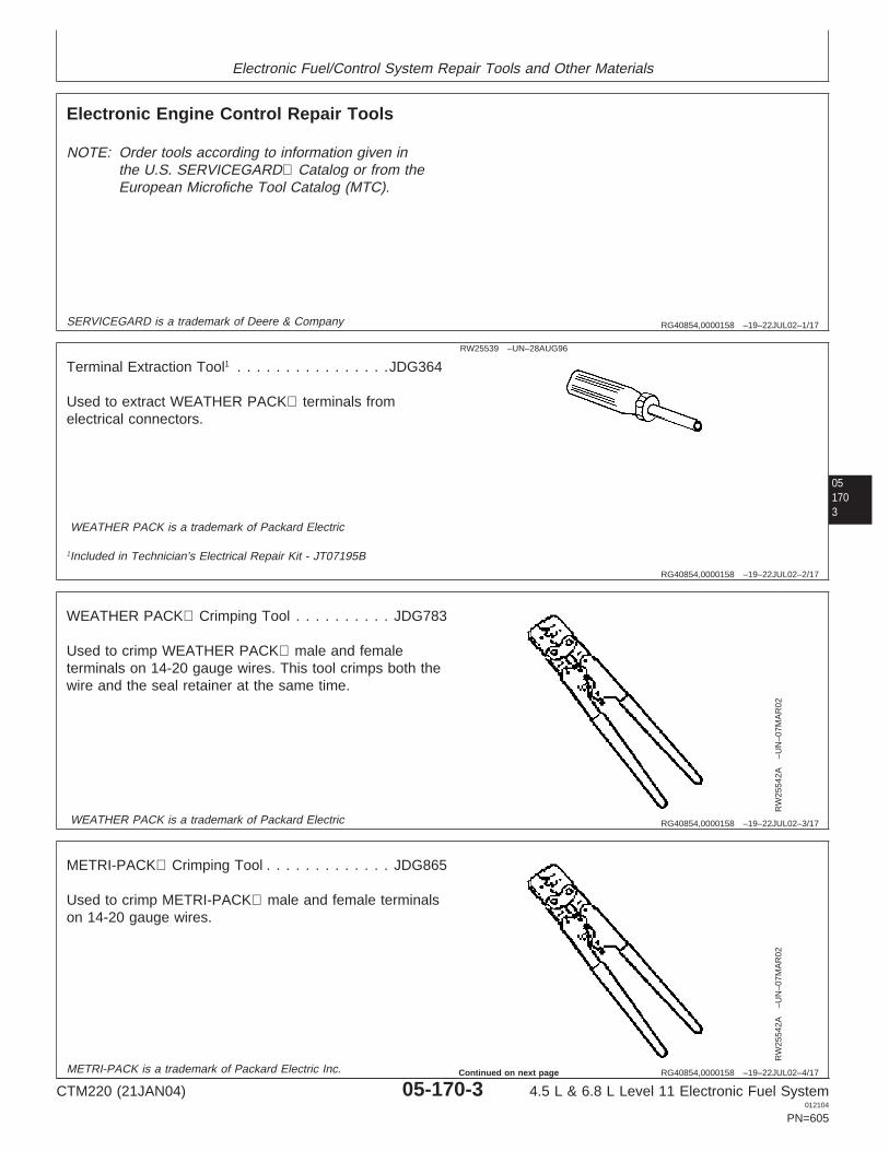
Electronic Fuel/Control System Repair Tools and Other Materials
RG40854,0000158 –19–22JUL02–1/17
Electronic Engine Control Repair Tools
NOTE: Order tools according to information given inthe U.S. SERVICEGARD Catalog or from theEuropean Microfiche Tool Catalog (MTC).
SERVICEGARD is a trademark of Deere & Company
051703
RG40854,0000158 –19–22JUL02–2/17
RW25539 –UN–28AUG96
Terminal Extraction Tool1 . . . . . . . . . . . . . . . .JDG364
Used to extract WEATHER PACK terminals fromelectrical connectors.
WEATHER PACK is a trademark of Packard Electric
1Included in Technician’s Electrical Repair Kit - JT07195B
RG40854,0000158 –19–22JUL02–3/17
RW
2554
2A–U
N–0
7MA
R02
WEATHER PACK Crimping Tool . . . . . . . . . . JDG783
Used to crimp WEATHER PACK male and femaleterminals on 14-20 gauge wires. This tool crimps both thewire and the seal retainer at the same time.
WEATHER PACK is a trademark of Packard Electric
RG40854,0000158 –19–22JUL02–4/17
RW
2554
2A–U
N–0
7MA
R02
METRI-PACK Crimping Tool . . . . . . . . . . . . . JDG865
Used to crimp METRI-PACK male and female terminalson 14-20 gauge wires.
METRI-PACK is a trademark of Packard Electric Inc.
CTM220 (21JAN04) 05-170-3 4.5 L & 6.8 L Level 11 Electronic Fuel System012104
PN=605
Continued on next page

Electronic Fuel/Control System Repair Tools and Other Materials
RG40854,0000158 –19–22JUL02–5/17
RG
1167
9–U
N–0
5FE
B01
Packard Crimper . . . . . . . . . . . . . . . . . . . . . . JDG707
Used to crimp WEATHER PACK, METRIPACK,SUMITOMO, and YAZAKI male and female terminals on12-20 gauge wires. This tool crimps the wire and the sealretainer separately.
05170
4
RG40854,0000158 –19–22JUL02–6/17
RW
2555
8–U
N–2
9AU
G96
Technician’s Electrical Repair Kit . . . . . . . . . . JT07195B
This kit is assembled with the most commonly usedterminal extraction tools used to repair wiring harnesseson John Deere applications. This kit includes thefollowing: JDG140 - CPC and Metrimate terminalextraction tool, JDG141 - CPC Blade Type terminalextraction tool, JDG361 - Deutsch 12-14 gauge terminalextraction/insertion tool, JDG362 - Deutsch 16-18 gaugeterminal extraction/insertion tool, JDG364 -WEATHERPACK terminal extraction tool, JDG776 -Metripack terminal extraction tool - Wide, JDG777 -METRI-PACK terminal extraction tool - Narrow, andJDG785 - Deutsch 6-8 gauge terminal extraction/insertiontool.
RG40854,0000158 –19–22JUL02–7/17
RW
2555
8–U
N–2
9AU
G96
Technician’s Electrical Repair Kit . . . . . . . . . . . JDG155
This kit is assembled with the most commonly usedterminal extraction tools used to repair wiring harnesseson John Deere applications. This kit includes thefollowing: JDG107 - Holding Plate, JDG139 - Sure-Sealterminal insertion tool, JDG140 - CPC and Metrimateterminal extraction tool, JDG141 - CPC Blade Typeterminal extraction tool, JDG142 - Mate-N-Lock terminalextraction tool, JDG143 - Mate-N-Lock terminal extractiontool, JDG144 - Universal Crimping Pliers, JDG145 -Electrician’s Pliers, JDG146 - Carrying Case, and JDG785- Deutsch 6-8 gauge terminal extraction/insertion tool.
CTM220 (21JAN04) 05-170-4 4.5 L & 6.8 L Level 11 Electronic Fuel System012104
PN=606
Continued on next page

Electronic Fuel/Control System Repair Tools and Other Materials
RG40854,0000158 –19–22JUL02–8/17
RG
1168
6–U
N–1
3FE
B01
Electrician’s Pliers1 . . . . . . . . . . . . . . . . . . . . JDG145
Used to cut, strip, and splice wires.
1Included in Technician’s Electrical Repair Kit - JDG155
051705
RG40854,0000158 –19–22JUL02–9/17
RW25541 –UN–20AUG96
METRI-PACK Extractor (Wide)1 . . . . . . . . . . . JDG776
Used to remove terminals from 56-Series, 280-Series, and630-Series METRI-PACK connectors.
METRI-PACK is a trademark of Packard Electric Inc.
1Included in Technician’s Electrical Repair Kit - JT07195B
RG40854,0000158 –19–22JUL02–10/17
RW25541 –UN–20AUG96
METRI-PACK Extractor (Narrow)1. . . . . . . . . . JDG777
Used to remove terminals from 150-SeriesMETRI-PACK, SUMITOMO, and YAZAKI connectors.
METRI-PACK is a trademark of Packard Electric Inc.
1Included in Technician’s Electrical Repair Kit - JT07195B
Continued on next page
CTM220 (21JAN04) 05-170-5 4.5 L & 6.8 L Level 11 Electronic Fuel System012104
PN=607

Electronic Fuel/Control System Repair Tools and Other Materials
RG40854,0000158 –19–22JUL02–11/17
RW
2554
0–U
N–0
6SE
P96
DEUTSCH Electrical Repair Tool Kit . . . . . . . .JDG359
Used to extract terminals from DEUTSCH electricalconnectors. A special crimping tool is also included tocrimp DEUTSCH terminals on wires. The following toolsare included: JDG360 - Deutsch Terminal Crimping Tool,JDG361 - Deutsch 12-14 gauge terminalextraction/insertion tool (set of 2), JDG362 - Deutsch16-18 gauge terminal extraction/insertion tool (set of 2),and JDG363 - Deutsch 20-24 gauge terminalextraction/insertion tool (set of 2)
05170
6
DEUTSCH is a trademark of Deutsch Co.
RG40854,0000158 –19–22JUL02–12/17
RG
1227
8–U
N–2
2AP
R02
Deutsch Extraction Tool
12—14 Gauge Extractor (Set of Two)1 . . . . . . . . JDG361
Used to remove terminals on 12-14 gauge wires inDEUTSCH connectors.
1Included in DEUTSCH Electrical Repair Kit - JDG359
Continued on next page
CTM220 (21JAN04) 05-170-6 4.5 L & 6.8 L Level 11 Electronic Fuel System012104
PN=608

Electronic Fuel/Control System Repair Tools and Other Materials
RG40854,0000158 –19–22JUL02–13/17
RG
1227
8–U
N–2
2AP
R02
Deutsch Extraction Tool
16—18 Gauge Extractor (Set of Two)1 . . . . . . . . JDG362
Used to remove terminals on 16-18 gauge wires inDEUTSCH connectors.
051707
1Included in DEUTSCH Electrical Repair Kit - JDG359
RG40854,0000158 –19–22JUL02–14/17
RG
1227
8–U
N–2
2AP
R02
Deutsch Extraction Tool
20—24 Gauge Extractor (Set of Two)1 . . . . . . . JDG363
Used to remove terminals on 20-24 gauge wires inDEUTSCH connectors.
1Included in DEUTSCH Electrical Repair Kit - JDG359
RG40854,0000158 –19–22JUL02–15/17
RG
1223
5–U
N–1
5MA
R02
Crimping Tool1 . . . . . . . . . . . . . . . . . . . . . . . JDG360
Used to crimp DEUTSCH closed barrel terminals on 12-24gauge wires.
1Included in DEUTSCH Electrical Repair Kit - JDG359
CTM220 (21JAN04) 05-170-7 4.5 L & 6.8 L Level 11 Electronic Fuel System012104
PN=609
Continued on next page
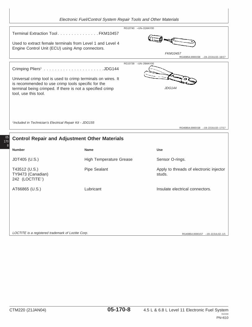
Electronic Fuel/Control System Repair Tools and Other Materials
RG40854,0000158 –19–22JUL02–16/17
RG10740 –UN–31MAY00
FKM10457
Terminal Extraction Tool . . . . . . . . . . . . . . . FKM10457
Used to extract female terminals from Level 1 and Level 4Engine Control Unit (ECU) using Amp connectors.
RG40854,0000158 –19–22JUL02–17/17
RG10739 –UN–26MAY00
JDG144
Crimping Pliers1 . . . . . . . . . . . . . . . . . . . . . .JDG144
Universal crimp tool is used to crimp terminals on wires. Itis recommended to use crimp tools specific for theterminal being crimped. If there is not a specified crimptool, use this tool.
05170
8
1Included in Technician’s Electrical Repair Kit - JDG155
RG40854,0000157 –19–22JUL02–1/1
Control Repair and Adjustment Other Materials
Number Name Use
JDT405 (U.S.) High Temperature Grease Sensor O-rings.
T43512 (U.S.) Pipe Sealant Apply to threads of electronic injectorTY9473 (Canadian) studs.242 (LOCTITE)
AT66865 (U.S.) Lubricant Insulate electrical connectors.
LOCTITE is a registered trademark of Loctite Corp.
CTM220 (21JAN04) 05-170-8 4.5 L & 6.8 L Level 11 Electronic Fuel System012104
PN=610

Group 180Diagnostic Service Tools
RG40854,000015A –19–22JUL02–1/12
Electronic Fuel/Control System Diagnostic Tools
NOTE: Order tools according to information given inthe U.S. SERVICEGARD Catalog or in the
European Microfiche Tool Catalog (MTC)unless otherwise noted.
SERVICEGARD is a trademark of Deere & Company.
051801
RG40854,000015A –19–22JUL02–2/12
RG
8518
–UN
–09O
CT
02
JDG998
Fuel System Cap Plug Kit . . . . . . . . . . . . . . . . JDG998
Used to protect the fuel system from dirt and debris whendisconnecting fuel system components during fuel transferpump pressure check.
RG40854,000015A –19–22JUL02–3/12
RG5162 –UN–23AUG88
JT05412
Universal Pressure Test Kit . . . . . . . . . . . . . . . JT05412
Used for testing engine oil pressure, intake manifoldpressure (turbo boost), and fuel transfer pump pressure.
Continued on next page
CTM220 (21JAN04) 05-180-1 4.5 L & 6.8 L Level 11 Electronic Fuel System012104
PN=611

Diagnostic Service Tools
RG40854,000015A –19–22JUL02–4/12
RG
8554
–UN
–26N
OV
97
JDIS122
ECU Communication Software Kit. . . . . . . . . . . JDIS122
Please refer to your John Deere Dealer website forinformation on obtaining the latest version of software.
05180
2
RG40854,000015A –19–22JUL02–5/12
NOTE: Available from John Deere Distribution ServiceCenter (DSC). United States and CanadianAgricultural dealers DO NOT ORDER withoutfirst contacting your Branch or TAM.
RG40854,000015A –19–22JUL02–6/12
RG
1174
7–U
N–0
9JU
L01
ECU Communication Hardware Kit . . . . . . . . . . JDIS121
Used with ECU Communication Software Kit. Together,the kits enable a Windows (’95, ’98, 2000, ME, and XP) orNT compatible computer to read information from theEngine Control Unit (ECU). The computer must be at leasta 486/66 with 8 MB of RAM and an IEEE 1284 compliantparallel port. This kit allows communication with all JohnDeere applications that use one of the following diagnosticconnectors: black 9-pin Deutsch diagnostic connector,gray 9-pin Deutsch diagnostic connector (early 8000series tractors), or the flat 6-pin Weatherpack diagnosticconnector (Lucas controllers). Not all of the components inthis kit are shown to the right.
Continued on next page
CTM220 (21JAN04) 05-180-2 4.5 L & 6.8 L Level 11 Electronic Fuel System012104
PN=612
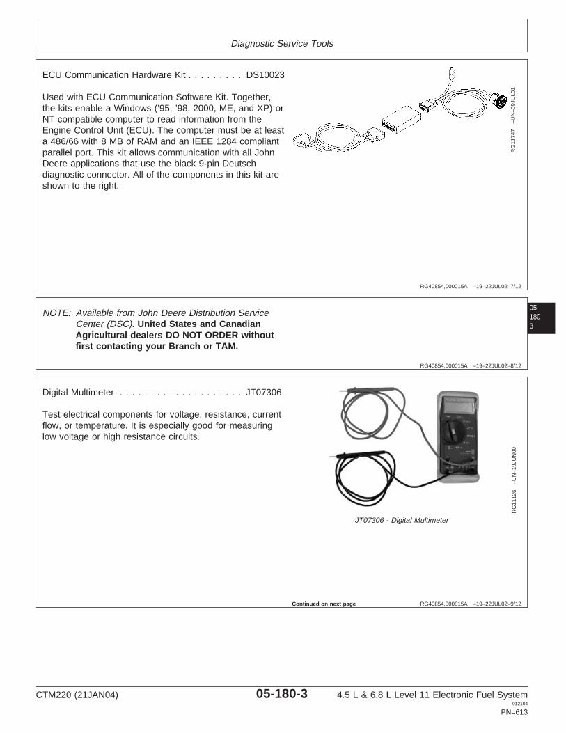
Diagnostic Service Tools
RG40854,000015A –19–22JUL02–7/12
RG
1174
7–U
N–0
9JU
L01
ECU Communication Hardware Kit . . . . . . . . . DS10023
Used with ECU Communication Software Kit. Together,the kits enable a Windows (’95, ’98, 2000, ME, and XP) orNT compatible computer to read information from theEngine Control Unit (ECU). The computer must be at leasta 486/66 with 8 MB of RAM and an IEEE 1284 compliantparallel port. This kit allows communication with all JohnDeere applications that use the black 9-pin Deutschdiagnostic connector. All of the components in this kit areshown to the right.
051803
RG40854,000015A –19–22JUL02–8/12
NOTE: Available from John Deere Distribution ServiceCenter (DSC). United States and CanadianAgricultural dealers DO NOT ORDER withoutfirst contacting your Branch or TAM.
RG40854,000015A –19–22JUL02–9/12
RG
1112
6–U
N–1
9JU
N00
JT07306 - Digital Multimeter
Digital Multimeter . . . . . . . . . . . . . . . . . . . . JT07306
Test electrical components for voltage, resistance, currentflow, or temperature. It is especially good for measuringlow voltage or high resistance circuits.
Continued on next page
CTM220 (21JAN04) 05-180-3 4.5 L & 6.8 L Level 11 Electronic Fuel System012104
PN=613

Diagnostic Service Tools
RG40854,000015A –19–22JUL02–10/12
RG
7056
–UN
–05D
EC
97
Flywheel Timing Tool . . . . . . . . . . . . . . . . . . .JDG820
Used to rotate engine flywheel to lock engine at “TDC” tocheck high pressure fuel pump timing. Use with JDE81-4Timing Pin.
05180
4
RG40854,000015A –19–22JUL02–11/12
RG5068 –UN–05DEC97
JDE81-4 Timing Pin
Timing Pin . . . . . . . . . . . . . . . . . . . . . . . . . JDE81-4
Used to lock engine at “TDC”. Use with JDG820 FlywheelTurning Tool.
RG40854,000015A –19–22JUL02–12/12
RG
8803
–UN
–26N
OV
97
JT07328
Connector Adapter Test Kit . . . . . . . . . . . . . . . JT07328
Used with JT05791 Digital Multimeter to make voltage andresistance measurements in control system wiring harnessconnectors. Can also be used to test terminals for properfit.
CTM220 (21JAN04) 05-180-4 4.5 L & 6.8 L Level 11 Electronic Fuel System012104
PN=614

Section 06Specifications
Contents
PagePage
Tractors - 7720 - 7820 Series - GovernorGroup 200—Repair SpecificationsMode Selection . . . . . . . . . . . . . . . . . . . . .06-210-39Unified Inch Bolt and Cap Screw Torque
Tractors - 7720 - 7820 Series - ECU TerminalValues . . . . . . . . . . . . . . . . . . . . . . . . . . . . .06-200-1Identification . . . . . . . . . . . . . . . . . . . . . . .06-210-40Metric Bolt and Cap Screw Torque Values . . .06-200-2
Electronic Fuel System Repair andAdjustment Specifications . . . . . . . . . . . . . .06-200-3
Electronic Engine Control Repair andAdjustment Specifications . . . . . . . . . . . . . .06-200-5
Group 210—Diagnostic SpecificationsFuel System Diagnostic Specifications . . . . . .06-210-1Application Specifications . . . . . . . . . . . . . . . .06-210-3Combines - Sensor Specifications. . . . . . . . . .06-210-6Combines - Torque Curve Selection . . . . . . . .06-210-8Combines - Governor Mode Selection. . . . . . .06-210-8Combines - ECU Terminal Identification . . . . .06-210-9Loaders - Sensor Specifications . . . . . . . . . .06-210-10
06Loaders - Torque Curve Selection. . . . . . . . .06-210-12Loaders - Governor Mode Selection . . . . . . .06-210-13Loaders - ECU Terminal Identification . . . . . .06-210-14Motor Graders - Sensor Specifications . . . . .06-210-15Motor Graders - Torque Curve Selection. . . .06-210-17Motor Graders - Governor Mode
Selection . . . . . . . . . . . . . . . . . . . . . . . . . .06-210-17Motor Graders - ECU Terminal
Identification . . . . . . . . . . . . . . . . . . . . . . .06-210-18OEM Engines - Sensor Specifications . . . . . .06-210-20OEM Engines - Torque Curve Selection . . . .06-210-22OEM Engines - Governor Mode Selection. . .06-210-23OEM Engines - ECU Terminal
Identification . . . . . . . . . . . . . . . . . . . . . . .06-210-24OEM Engines - Electronic Control System
Wiring Diagram . . . . . . . . . . . . . . . . . . . . .06-210-26OEM Engines - 4.5L & 6.8L Instrument
Panel/Engine Start Components Electrical WiringDiagram. . . . . . . . . . . . . . . . . . . . . . . . . . .06-210-28
6020 Tractors - Sensor Specifications . . . . . .06-210-306020 Tractors - Torque Curve Selection . . . .06-210-326020 Tractors - Governor Mode Selection. . .06-210-336020 Tractors - ECU Terminal
Identification . . . . . . . . . . . . . . . . . . . . . . .06-210-34Tractors - 7720 - 7820 Series - Sensor
Specifications. . . . . . . . . . . . . . . . . . . . . . .06-210-36Tractors - 7720 - 7820 Series - Torque Curve
Selection . . . . . . . . . . . . . . . . . . . . . . . . . .06-210-38
CTM220 (21JAN04) 06-1 4.5 L & 6.8 L Level 11 Electronic Fuel System012104
PN=1

Contents
06
CTM220 (21JAN04) 06-2 4.5 L & 6.8 L Level 11 Electronic Fuel System012104
PN=2

Group 200Repair Specifications
062001
RG40854,000015B –19–22JUL02–1/1
Unified Inch Bolt and Cap Screw Torque Values
TO
RQ
1A–U
N–2
7SE
P99
Top, SAE Grade and Head Markings; Bottom, SAE Grade and Nut Markings
Grade 1 (No Mark) Grade 2a (No Mark) Grade 5, 5.1 or 5.2 Grade 8 or 8.2
Size Lubricatedb Dryc Lubricatedb Dryc Lubricatedb Dryc Lubricatedb Dryc
N•m(lb-ft) N•m(lb-ft) N•m(lb-ft) N•m(lb-ft) N•m(lb-ft) N•m(lb-ft) N•m(lb-ft) N•m(lb-ft)
1/4 3.8 (2.8) 4.7 (3.5) 6 (4.4) 7.5 (5.5) 9.5 (7) 12 (9) 13.5 (10) 17 (12.5)
5/16 7.7 (5.7) 9.8 (7.2) 12 (9) 15.5 (11.5) 19.5 (14.5) 25 (18.5) 28 (20.5) 35 (26)
3/8 13.5 (10) 17.5 (13) 22 (16) 27.5 (20) 35 (26) 44 (32.5) 49 (36) 63 (46)
7/16 22 (16) 28 (20.5) 35 (26) 44 (32.5) 56 (41) 70 (52) 80 (59) 100 (74)
1/2 34 (25) 42 (31) 53 (39) 67 (49) 85 (63) 110 (80) 120 (88) 155 (115)
9/16 48 (35.5) 60 (45) 76 (56) 95 (70) 125 (92) 155 (115) 175 (130) 220 (165)
5/8 67 (49) 85 (63) 105 (77) 135 (100) 170 (125) 215 (160) 240 (175) 305 (225)
3/4 120 (88) 150 (110) 190 (140) 240 (175) 300 (220) 380 (280) 425 (315) 540 (400)
7/8 190 (140) 240 (175) 190 (140) 240 (175) 490 (360) 615 (455) 690 (510) 870 (640)
1 285 (210) 360 (265) 285 (210) 360 (265) 730 (540) 920 (680) 1030 (760) 1300 (960)
1-1/8 400 (300) 510 (375) 400 (300) 510 (375) 910 (670) 1150 (850) 1450 (1075) 1850 (1350)
1-1/4 570 (420) 725 (535) 570 (420) 725 (535) 1280 (945) 1630 (1200) 2050 (1500) 2600 (1920)
1-3/8 750 (550) 950 (700) 750 (550) 950 (700) 1700 (1250) 2140 (1580) 2700 (2000) 3400 (2500)
1-1/2 990 (730) 1250 (930) 990 (730) 1250 (930) 2250 (1650) 2850 (2100) 3600 (2650) 4550 (3350)a Grade 2 applies for hex cap screws (not hex bolts) up to 6 in. (152 mm) long. Grade 1 applies for hex cap screws over 6 in. (152 mm) long,and for all other types of bolts and screws of any length.b "Lubricated" means coated with a lubricant such as engine oil, or fasteners with phosphate and oil coatings.c "Dry" means plain or zinc plated without any lubrication.
DO NOT use these values if a different torque value or tightening Make sure fastener threads are clean and that you properly startprocedure is given for a specific application. Torque values listed are thread engagement. This will prevent them from failing whenfor general use only. Check tightness of fasteners periodically. tightening.
Shear bolts are designed to fail under predetermined loads. Always Tighten plastic insert or crimped steel-type lock nuts to approximatelyreplace shear bolts with identical grade. 50 percent of the dry torque shown in the chart, applied to the nut,
not to the bolt head. Tighten toothed or serrated-type lock nuts to thefull torque value.
Fasteners should be replaced with the same or higher grade. Ifhigher grade fasteners are used, these should only be tightened tothe strength of the original.
CTM220 (21JAN04) 06-200-1 4.5 L & 6.8 L Level 11 Electronic Fuel System012104
PN=617

Repair Specifications
06200
2
RG40854,000015C –19–22JUL02–1/1
Metric Bolt and Cap Screw Torque Values
TO
RQ
2–U
N–0
7SE
P99
Top, Property Class and Head Markings; Bottom, Property Class and Nut Markings
Class 4.8 Class 8.8 or 9.8 Class 10.9 Class 12.9
Size Lubricateda Dryb Lubricateda Dryb Lubricateda Dryb Lubricateda Dryb
N•m(lb-ft) N•m(lb-ft) N•m(lb-ft) N•m(lb-ft) N•m(lb-ft) N•m(lb-ft) N•m(lb-ft) N•m(lb-ft)
M6 4.7 (3.5) 6 (4.4) 9 (6.6) 11.5 (8.5) 13 (9.5) 16.5 (12.2) 15.5 (11.5) 19.5 (14.5)
M8 11.5 (8.5) 14.5 (10.7) 22 (16) 28 (20.5) 32 (23.5) 40 (29.5) 37 (27.5) 47 (35)
M10 23 (17) 29 (21) 43 (32) 55 (40) 63 (46) 80 (59) 75 (55) 95 (70)
M12 40 (29.5) 50 (37) 75 (55) 95 (70) 110 (80) 140 (105) 130 (95) 165 (120)
M14 63 (46) 80 (59) 120 (88) 150 (110) 175 (130) 220 (165) 205 (150) 260 (190)
M16 100 (74) 125 (92) 190 (140) 240 (175) 275 (200) 350 (255) 320 (235) 400 (300)
M18 135 (100) 170 (125) 265 (195) 330 (245) 375 (275) 475 (350) 440 (325) 560 (410)
M20 190 (140) 245 (180) 375 (275) 475 (350) 530 (390) 675 (500) 625 (460) 790 (580)
M22 265 (195) 330 (245) 510 (375) 650 (480) 725 (535) 920 (680) 850 (625) 1080 (800)
M24 330 (245) 425 (315) 650 (480) 820 (600) 920 (680) 1150 (850) 1080 (800) 1350 (1000)
M27 490 (360) 625 (460) 950 (700) 1200 (885) 1350 (1000) 1700 (1250) 1580 (1160) 2000 (1475)
M30 660 (490) 850 (625) 1290 (950) 1630 (1200) 1850 (1350) 2300 (1700) 2140 (1580) 2700 (2000)
M33 900 (665) 1150 (850) 1750 (1300) 2200 (1625) 2500 (1850) 3150 (2325) 2900 (2150) 3700 (2730)
M36 1150 (850) 1450 (1075) 2250 (1650) 2850 (2100) 3200 (2350) 4050 (3000) 3750 (2770) 4750 (3500)a "Lubricated" means coated with a lubricant such as engine oil, or fasteners with phosphate and oil coatings.b "Dry" means plain or zinc plated without any lubrication.
DO NOT use these values if a different torque value or tightening Make sure fastener threads are clean and that you properly startprocedure is given for a specific application. Torque values listed are thread engagement. This will prevent them from failing whenfor general use only. Check tightness of fasteners periodically. tightening.
Shear bolts are designed to fail under predetermined loads. Always Tighten plastic insert or crimped steel-type lock nuts to approximatelyreplace shear bolts with identical property class. 50 percent of the dry torque shown in the chart, applied to the nut,
not to the bolt head. Tighten toothed or serrated-type lock nuts to thefull torque value.
Fasteners should be replaced with the same or higher property class.If higher property class fasteners are used, these should only betightened to the strength of the original.
CTM220 (21JAN04) 06-200-2 4.5 L & 6.8 L Level 11 Electronic Fuel System012104
PN=618

Repair Specifications
062003
RG40854,000013E –19–15JUL02–1/2
Electronic Fuel System Repair and Adjustment Specifications
Item Measurement Specification
Pre-filter Inlet and Outlet Lines Torque 9 N•m (6.6 lb-ft)
Pre-filter Mounting Torque 73 N•m (53.8 lb-ft)Bracket-to-Cylinder Head CapScrews
Pre-filter Fuel Filter Base-to-Bracket Torque 50 N•m (36.9 lb-ft)Cap Screws
Final Fuel Filter Inlet and Outlet Torque 9 N•m (6.6 lb-ft)Lines
Final Fuel Filter Outlet Line Torque 9 N•m (6.6 lb-ft)
Air Bleed Valve Fitting (Combine Torque 20 N•m (14.8 lb-ft)engines)
Final Fuel Filter Base-to-Bracket Torque 50 N•m (36.9 lb-ft)
Final Fuel Filter Bracket to Cylinder Torque 73 N•m (53.4 lb-ft)Head
Fuel Transfer Pump Cap Screws Torque 30 N•m (22 lb-ft)(OEM engines only)
High Pressure Fuel Pump to Adapter Torque 40 N•m (29.5 lb-ft)Plate
High Pressure Fuel Pump Gear Nut Torque 68 N•m (50.1 lb-ft)
High Pressure Fuel Pump Adapter Torque 40 N•m (29.5 lb-ft)Plate to Front Cover
High Pressure Fuel Lines - Injection Torque 27 N•m (19.9 lb-ft)Pump Fitting
High Pressure Fuel Lines - High Torque 27 N•m (19.9 lb-ft)Pressure Common Rail Fitting
High Pressure Fuel Pump Leak-off Torque 6 N•m (4.4 lb-ft)Line Fitting
High Pressure Fuel Pump Inlet Filter Torque 18 N•m (13.3 lb-ft)Plug
CTM220 (21JAN04) 06-200-3 4.5 L & 6.8 L Level 11 Electronic Fuel System012104
PN=619
Continued on next page

Repair Specifications
06200
4
RG40854,000013E –19–15JUL02–2/2
Item Measurement Specification
High Pressure Common Rail Bracket Torque 52 N•m (38.4 lb-ft)to Engine
High Pressure Common Rail to Torque 52 N•m (38.4 lb-ft)Bracket
High Pressure Common Rail - Torque 27 N•m (19.9 lb-ft)Delivery Lines to Electronic Injectors
High Pressure Common Rail - Fuel Torque 27 N•m (20 lb-ft)Inlet Lines
High Pressure Pump - Fuel Outlet Torque 27 N•m (20 lb-ft)Lines
High Pressure Rail Leak-off Line Torque 6 N•m (4.4 lb-ft)Fitting
Flow Damper Torque 176 N•m (130 lb-ft)
Fitting - High Pressure Injection Line Torque 27 N•m (20 lb-ft)to High Pressure Common Rail
High Pressure Rail Delivery Fuel Torque 27 N•m (20 lb-ft)Line - Fitting at Side Feed TubeRetaining Nut
First Torque - Side Feed Tube Torque 5 N•m (3.7 lb-ft)Retaining Nut
Hold Down Clamp Bolt Torque 47 N•m (34.7 lb-ft)
Second Torque - Side Feed Tube Torque 35 N•m (25.8 lb-ft)Retaining Nut
High Pressure Delivery Line Fitting Torque 27 N•m (19.9 lb-ft)
Injector Solenoid Wire Retaining Nut Torque 2 N•m (1.5 lb-ft) (18 lb-in.)
Heat Shield Cylinder Head Cap Torque 60 N•m (44 lb-ft)Screws
Heat Shield Rocker Arm Carrier Cap Torque 10 N•m (7.4 lb-ft)Screws
Injector Leak-off Fitting Torque 18 N•m (13.3 lb-ft)
CTM220 (21JAN04) 06-200-4 4.5 L & 6.8 L Level 11 Electronic Fuel System012104
PN=620

Repair Specifications
06RG40854,000013F –19–15JUL02–1/1
Electronic Engine Control Repair and Adjustment Specifications
Item Measurement Specification
Fuel Temperature Sensor Torque 10 N•m (7 lb-ft)
Manifold Air Temperature (MAT) Torque 10 N•m (7 lb-ft)Sensor
Oil Pressure Sensor Torque 9 N•m (7 lb-ft)
Fuel Rail Pressure Sensor Torque 98 N•m (72 lb-ft)
Crankshaft Position Sensor Torque 14 N•m (10 lb-ft)
Pump Position Sensor Torque 14 N•m (10 lb-ft)
Glow Plug Torque 15 N•m (11 lb-ft)
Heat Shield Cylinder Head Cap Torque 60 N•m (44 lb-ft)Screws
Heat Shield Rocker Arm Carrier Cap Torque 10 N•m (7.4 lb-ft)Screws
2005
CTM220 (21JAN04) 06-200-5 4.5 L & 6.8 L Level 11 Electronic Fuel System012104
PN=621

Repair Specifications
06200
6
CTM220 (21JAN04) 06-200-6 4.5 L & 6.8 L Level 11 Electronic Fuel System012104
PN=622

Group 210Diagnostic Specifications
RG40854,0000140 –19–15JUL02–1/1
Fuel System Diagnostic Specifications
Item Measurement Specification
Minimum Fuel Transfer Pump Cranking 30 kPa (0.3 bar) (4.4 psi)Pressure Running (Low Idle) 40 kPa (0.4 bar) (5.8 psi)
Minimum Fuel Rail Pressure Cranking 20 MPa (200 bar) (2900 psi)Running (Low Idle) 35 MPa (350 bar) (5076 psi)
062101
CTM220 (21JAN04) 06-210-1 4.5 L & 6.8 L Level 11 Electronic Fuel System012104
PN=623

Diagnostic Specifications
06210
2
CTM220 (21JAN04) 06-210-2 4.5 L & 6.8 L Level 11 Electronic Fuel System012104
PN=624

Diagnostic Specifications
062103
RG40854,0000145 –19–16JUL02–1/2
Application Specifications
Below is an overview of the specfications listed forapplications in the next few pages.
• Combines– Sensor Specifications - See COMBINES -
SENSOR SPECIFICATIONS later in this Group.– Torque Curve Selection - See COMBINES -
TORQUE CURVE SELECTION later in thisGroup.
– Governor Mode Selection - See COMBINES -GOVERNOR MODE SELECTION later in thisGroup.
– ECU Terminal Identification - See COMBINES -ECU TERMINAL IDENTIFICATION later in thisGroup.
– Vehicle Wiring - See Vehicle manual.• Loaders
– Sensor Specifications - See LOADERS -SENSOR SPECIFICATIONS later in this Group.
– Torque Curve Selection - See LOADERS -TORQUE CURVE SELECTION later in thisGroup.
– Governor Mode Selection - See LOADERS -GOVERNOR MODE SELECTION later in thisGroup.
– ECU Terminal Identification - See LOADERS -ECU TERMINAL IDENTIFICATION later in thisGroup.
– Vehicle Wiring - See Vehicle manual.• Motor Graders
– Sensor Specifications - See MOTOR GRADERS -SENSOR SPECIFICATIONS later in this Group.
– Torque Curve Selection - See MOTORGRADERS - TORQUE CURVE SELECTION laterin this Group.
– Governor Mode Selection - See MOTORGRADERS - GOVERNOR MODE SELECTIONlater in this Group.
– ECU Terminal Identification - See MOTORGRADERS - ECU TERMINAL IDENTIFICATIONlater in this Group.
– Vehicle Wiring - See Vehicle manual.• OEM Engines
– Sensor Specifications - See OEM ENGINES -SENSOR SPECIFICATIONS later in this Group.
– Torque Curve Selection - See OEM ENGINES -TORQUE CURVE SELECTION later in thisGroup.
– Governor Mode Selection - See OEM ENGINES -GOVERNOR MODE SELECTION later in thisGroup.
– ECU Terminal Identification - See OEM ENGINES- ECU TERMINAL IDENTIFICATION later in thisGroup.
– Electronic Control System Wiring Diagram - SeeOEM ENGINES - ELECTRONIC CONTROLSYSTEM WIRING DIAGRAM later in this Group.
– 4.5L & 6.8L OEM Application InstrumentPanel/Engine Start Components Electrical WiringDiagram - See OEM ENGINES - 4.5L & 6.8LINSTRUMENT PANEL/ENGINE STARTCOMPONENTS ELECTRICAL WIRINGDIAGRAM later in this Group.
• Tractors - 6020 Series– Sensor Specifications - See 6020 TRACTORS -
SENSOR SPECIFICATIONS later in this Group.– Torque Curve Selection - See 6020 TRACTORS -
TORQUE CURVE SELECTION later in thisGroup.
– Governor Mode Selection - See 6020 TRACTORS- GOVERNOR MODE SELECTION later in thisGroup.
– ECU Terminal Identification - See 6020TRACTORS - ECU TERMINAL IDENTIFICATIONlater in this Group.
– Vehicle Wiring - See Vehicle manual.• Tractors - 7220-7520 Series
– Sensor Specifications - See 7220-7520TRACTORS - SENSOR SPECIFICATIONS laterin this Group.
– Torque Curve Selection - See 7220-7520TRACTORS - TORQUE CURVE SELECTIONlater in this Group.
– Governor Mode Selection - See 7220-7520TRACTORS - GOVERNOR MODE SELECTIONlater in this Group.
CTM220 (21JAN04) 06-210-3 4.5 L & 6.8 L Level 11 Electronic Fuel System012104
PN=625
Continued on next page

Diagnostic Specifications
RG40854,0000145 –19–16JUL02–2/2
– ECU Terminal Identification - See 7220-7520TRACTORS - ECU TERMINAL IDENTIFICATIONlater in this Group.
– Vehicle Wiring - See Vehicle manual.• Tractors - 7720-7820 Series
– Sensor Specifications - See 7720-7820TRACTORS - SENSOR SPECIFICATIONS laterin this Group.
– Torque Curve Selection - See 7720-7820TRACTORS - TORQUE CURVE SELECTIONlater in this Group.
– Governor Mode Selection - See 7720-7820TRACTORS - GOVERNOR MODE SELECTIONlater in this Group.
– ECU Terminal Identification - See 7720-7820TRACTORS - ECU TERMINAL IDENTIFICATIONlater in this Group.
– Vehicle Wiring - See Vehicle manual.
06210
4
CTM220 (21JAN04) 06-210-4 4.5 L & 6.8 L Level 11 Electronic Fuel System012104
PN=626

Diagnostic Specifications
062105
CTM220 (21JAN04) 06-210-5 4.5 L & 6.8 L Level 11 Electronic Fuel System012104
PN=627

Diagnostic Specifications
RG40854,0000144 –19–16JUL02–1/3
Combines - Sensor Specifications
The specifications shown below are voltage, pressure,and temperature parameters that the Engine Control Unit(ECU) uses to determine whether a Diagnostic TroubleCode (DTC) is set for a given sensor
Continued on next page
06210
6
CTM220 (21JAN04) 06-210-6 4.5 L & 6.8 L Level 11 Electronic Fuel System012104
PN=628

Diagnostic Specifications
062107
RG40854,0000144 –19–16JUL02–2/3
Sensor Specifications for Combines
Sensor SPN-FMI Measured Sensor Out of Range Value DerateParameter
Fuel Rail Pressure 000094.03 High Input Voltage Above 4.89 Volts ECU derates engine 50%per minute until engineruns at 50% of full power.
000094.04 Low Input Voltage Below 0.9 Volts ECU derates engine 50%per minute until engineruns at 50% of full power.
Manifold Air Temperature 000105.00 Extremely High Exceeds100°C (212°F) ECU derates engine 20%(MAT) per minute until the
engine until engine runsat 60% of full power.
000105.03 High Input Voltage Above 4.9 Volts High MAT engineprotection is disabled.
000105.04 Low Input Voltage Below 0.1 Volts High MAT engineprotection is disabled.
000105.16 Moderately High Exceeds 88°C (190°F) ECU derates engine 2%per minute until theengine until engine runsat 80% of full power.
Engine Coolant 000110.00 Most Severe Temperature Exceeds 120°C (248°F) ECU derates engine 60%Temperature (ECT) per minute until engine
runs at 40% of full power.
000110.03 High Input Voltage Exceeds 4.9 Volts High ECT engineprotection is disabled.
000110.04 Low Input Voltage Below 0.1 Volts High ECT engineprotection is disabled.
000110.15 Least Severe Exceeds 105°C (221°F) ECU derates engine 2%Temperature per minute until engine
runs at 95% of full power.
000110.16 Moderately Severe Exceeds 110°C (230°F) ECU derates engine 40%Temperature per minute until engine
runs at 60% of full power.
Fuel Temperature 000174.03 High Input Voltage Exceeds 4.9 Volts High fuel temperatureengine protection isdisabled.
000174.04 Low Input Voltage Below 0.1 Volts High fuel temperatureengine protection isdisabled.
000174.16 Moderately High Exceeds 80°C (176°F) ECU derates engine 2%Temperature per minute until engine
runs at 80% of full power.
Crankshaft Position 000637.02 Input Noise Noise detection of 100% ECU derates engine 50%per minute until engineruns at 50% of full power.
CTM220 (21JAN04) 06-210-7 4.5 L & 6.8 L Level 11 Electronic Fuel System012104
PN=629
Continued on next page

Diagnostic Specifications
RG40854,0000144 –19–16JUL02–3/3
Sensor Specifications for Combines
000637.07 Crankshaft Position Speed sensors out of ECU derates engine 50%mismatch with Pump sync. per minute until enginePosition runs at 50% of full power.
000637.08 Input Missing No signal detected ECU derates engine 50%per minute until engineruns at 50% of full power.
06 RG40854,0000143 –19–16JUL02–1/1
Combines - Torque Curve Selection
Torque Curve Selection for Combines
Torque Curve # on DST orSERVICE ADVISOR Conditions for Torque Curve
1 Normal operation
2108
SERVICE ADVISOR is a trademark of Deere & Company
RG40854,0000142 –19–16JUL02–1/1
Combines - Governor Mode Selection
Desired Speed Governor Selection for Combines
Mode Selected on DST orSERVICE ADVISOR Conditions
0 Normal droop
Max. Speed Governor Selection for Combines
Mode Selected on DST orSERVICE ADVISOR Conditions:
9 Normal droop
SERVICE ADVISOR is a trademark of Deere & Company
CTM220 (21JAN04) 06-210-8 4.5 L & 6.8 L Level 11 Electronic Fuel System012104
PN=630

Diagnostic Specifications
062109
RG40854,0000141 –19–16JUL02–1/1
Combines - ECU Terminal Identification
ECU Terminal Function ECU Terminal # Sensor Connector Terminal#
Switched Battery E3 N/Aa
Unswitched Battery B1, B2 N/Aa
System Ground C2, C3 N/Aa
CAN High L1 N/Aa
CAN Low L2 N/Aa
Fuel Rail Pressure 5V Sensor Supply R3 3
Fuel Rail Pressure Sensor Ground P3 2
Fuel Rail Pressure Input R1 1
Engine Oil Pressure Input D3 B
Air Filter Vacuum Input D2 B
Sensor Ground 2 N3 Varies depending on sensor/switch
Manifold Air Temperature (MAT) Input Y2 A
Engine Coolant Temperature (ECT) Input X2 A
Fuel Temperature Input X3 1
Sensor Ground 1 P2 Varies depending on sensor/switch
Crank Position Input W1 A
Crank Position Return W2 B
Pump Position Input X1 B
Pump Position Return W3 A
Pump Solenoid Return J1 1
Pump Solenoid Supply H2 2
Glow Plug Control J3 NAa
Glow Plug Diagnostic F3 NAa
Transfer Pump Control K1 NAa
Cylinder 1, 2, and 3 90V Supply A2 4
Cylinder 4, 5, and 6 90V Supply A1 9
Cylinder 1 Control E1 1
Cylinder 2 Control F1 2
Cylinder 3 Control H1 3
Cylinder 4 Control F2 10
Cylinder 5 Control E2 11
Cylinder 6 Control G1 12aN/A = Not Applicable
CTM220 (21JAN04) 06-210-9 4.5 L & 6.8 L Level 11 Electronic Fuel System012104
PN=631

Diagnostic Specifications
RG41221,0000128 –19–14APR03–1/3
Loaders - Sensor Specifications
The specifications shown below are voltage, pressure,and temperature parameters that the Engine Control Unit(ECU) uses to determine whether a Diagnostic TroubleCode (DTC) is set for a given sensor
Continued on next page
06210
10
CTM220 (21JAN04) 06-210-10 4.5 L & 6.8 L Level 11 Electronic Fuel System012104
PN=632

Diagnostic Specifications
0621011
RG41221,0000128 –19–14APR03–2/3
Sensor Specifications for Loaders
Sensor SPN-FMI Measured Sensor Out of Range Value DerateParameter
Fuel Rail Pressure 000094.03 High Input Voltage Above 4.89 Volts ECU derates engine 50%per minute until engineruns at 50% of full power.
000094.04 Low Input Voltage Below 0.9 Volts ECU derates engine 50%per minute until engineruns at 50% of full power.
Oil Pressure 000100.01 Extremely Low Pressure Below an extremely low ECU will shut the engineengine oil pressure. This down immediately.pressure increases withengine speed.
000100.03 High Input Voltage Above 4.5 Volts Low oil pressure engineprotection is disabled.
000100.04 Low Input Voltage Below 0.3 Volts Low oil pressure engineprotection is disabled.
000100.16 High Pressure Oil pressure is above the The ECU does NOThigh pressure derate the engine.specification.
000100.18 Moderately Low Pressure Below a moderately low ECU derates engine 2%engine oil pressure. This per minute until enginepressure increases with runs at 90% of full power.engine speed.
Manifold Air Temperature 000105.03 High Input Voltage Above 4.9 Volts High MAT engine(MAT) protection is disabled.
000105.04 Low Input Voltage Below 0.1 Volts High MAT engineprotection is disabled.
000105.16 Moderately High Exceeds 88°C (190°F) ECU derates engine 2%per minute until theengine until engine runsat 80% of full power.
Engine Coolant 000110.00 Most Severe Temperature Exceeds 110°C (230°F) ECU derates engine 20%Temperature (ECT) per minute until engine
runs at 75% of full power.
000110.03 High Input Voltage Exceeds 4.9 Volts High ECT engineprotection is disabled.
000110.04 Low Input Voltage Below 0.1 Volts High ECT engineprotection is disabled.
000110.15 Least Severe Exceeds 105°C (221°F) ECU derates engine 2%Temperature per minute until engine
runs at 95% of full power.
000110.16 Moderately Severe Exceeds 108°C (226°F) ECU derates engine 2%Temperature per minute until engine
runs at 90% of full power.
Fuel Temperature 000174.03 High Input Voltage Exceeds 4.9 Volts High fuel temperatureengine protection isdisabled.
CTM220 (21JAN04) 06-210-11 4.5 L & 6.8 L Level 11 Electronic Fuel System012104
PN=633
Continued on next page

Diagnostic Specifications
06 RG41221,0000128 –19–14APR03–3/3
Sensor Specifications for Loaders
000174.04 Low Input Voltage Below 0.1 Volts High fuel temperatureengine protection isdisabled.
000174.16 Moderately High Exceeds 65°C (149°F) ECU does not derate theTemperature engine. 2% per minute
until engine runs at 80%of full power.
Crankshaft Position 000637.02 Input Noise Noise detection of 100% ECU derates engine 50%per minute until engineruns at 50% of full power.
000637.07 Crankshaft Position Speed sensors out of ECU derates engine 50%mismatch with Pump sync. per minute until enginePosition runs at 50% of full power.
000637.08 Input Missing No signal detected ECU derates engine 50%per minute until engineruns at 50% of full power.
21012
RG41221,0000129 –19–14APR03–1/1
Loaders - Torque Curve Selection
Torque Curve Selection for Loaders
Torque Curve # on DST orSERVICE ADVISOR Conditions for Torque Curve
1 Normal operation
SERVICE ADVISOR is a trademark of Deere & Company
CTM220 (21JAN04) 06-210-12 4.5 L & 6.8 L Level 11 Electronic Fuel System012104
PN=634

Diagnostic Specifications
RG41221,000012A –19–14APR03–1/1
Loaders - Governor Mode Selection
Desired Speed Governor Selection for Loaders
Mode Selected on DST orSERVICE ADVISOR Conditions
0 Normal droop
Max. Speed Governor Selection for Loaders
Mode Selected on DST orSERVICE ADVISOR Conditions:
9 Normal droop
0621013
SERVICE ADVISOR is a trademark of Deere & Company
CTM220 (21JAN04) 06-210-13 4.5 L & 6.8 L Level 11 Electronic Fuel System012104
PN=635

Diagnostic Specifications
06210
14
RG41221,000012B –19–14APR03–1/1
Loaders - ECU Terminal Identification
ECU Terminal Function ECU Terminal # Sensor Connector Terminal#
Switched Battery E3 N/Aa
Unswitched Battery B1, B2 N/Aa
System Ground C2, C3 N/Aa
CAN High L1 N/Aa
CAN Low L2 N/Aa
Fuel Rail Pressure 5V Sensor Supply R3 3
Fuel Rail Pressure Sensor Ground P3 2
Fuel Rail Pressure Input R1 1
Engine Oil Pressure Input T2 B
Air Filter Vacuum Input F3 B
Sensor Ground 2 P2 Varies depending on sensor/switch
Manifold Air Temperature (MAT) Input Y2 A
Engine Coolant Temperature (ECT) Input X2 A
Fuel Temperature Input X3 1
Sensor Ground 1 N3 Varies depending on sensor/switch
Crank Position Input W1 A
Crank Position Return W2 B
Pump Position Input X1 B
Pump Position Return W3 A
Pump Solenoid Return J1 1
Pump Solenoid Supply H2 2
Cylinder 1, 2, and 3 90V Supply A2 4
Cylinder 4, 5, and 6 90V Supply A1 9
Cylinder 1 Control E1 1
Cylinder 2 Control F1 2
Cylinder 3 Control H1 3
Cylinder 4 Control F2 10
Cylinder 5 Control E2 11
Cylinder 6 Control G1 12aN/A = Not Applicable
CTM220 (21JAN04) 06-210-14 4.5 L & 6.8 L Level 11 Electronic Fuel System012104
PN=636

Diagnostic Specifications
RG41221,000012F –19–14APR03–1/3
Motor Graders - Sensor Specifications
The specifications shown below are voltage, pressure,and temperature parameters that the Engine Control Unit(ECU) uses to determine whether a Diagnostic TroubleCode (DTC) is set for a given sensor
Continued on next page
0621015
CTM220 (21JAN04) 06-210-15 4.5 L & 6.8 L Level 11 Electronic Fuel System012104
PN=637

Diagnostic Specifications
06210
16
RG41221,000012F –19–14APR03–2/3
Sensor Specifications for Motor Graders
Sensor SPN-FMI Measured Sensor Out of Range Value DerateParameter
Fuel Rail Pressure 000094.03 High Input Voltage Above 4.89 Volts ECU derates engine 50%per minute until engineruns at 50% of full power.
000094.04 Low Input Voltage Below 0.9 Volts ECU derates engine 50%per minute until engineruns at 50% of full power.
Oil Pressure 000100.01 Extremely Low Pressure Below an extremely low ECU will shut the engineengine oil pressure. This down immediately.pressure increases withengine speed.
000100.03 High Input Voltage Above 4.5 Volts Low oil pressure engineprotection is disabled.
000100.04 Low Input Voltage Below 0.3 Volts Low oil pressure engineprotection is disabled.
000100.18 Moderately Low Pressure Below a moderately low ECU derates engine 2%engine oil pressure. This per minute until enginepressure increases with runs at 80% of full power.engine speed.
Manifold Air Temperature 000105.03 High Input Voltage Above 4.9 Volts High MAT engine(MAT) protection is disabled.
000105.04 Low Input Voltage Below 0.1 Volts High MAT engineprotection is disabled.
000105.16 Moderately High Exceeds 88°C (190°F) ECU derates engine 2%per minute until theengine until engine runsat 80% of full power.
Engine Coolant 000110.00 Most Severe Temperature Exceeds 110°C (230°F) ECU derates engine 20%Temperature (ECT) per minute until engine
runs at 75% of full power.
000110.03 High Input Voltage Exceeds 4.9 Volts High ECT engineprotection is disabled.
000110.04 Low Input Voltage Below 0.1 Volts High ECT engineprotection is disabled.
000110.15 Least Severe Exceeds 105°C (221°F) ECU derates engine 2%Temperature per minute until engine
runs at 95% of full power.
000110.16 Moderately Severe Exceeds 108°C (226°F) ECU derates engine 2%Temperature per minute until engine
runs at 90% of full power.
Fuel Temperature 000174.03 High Input Voltage Exceeds 4.9 Volts High fuel temperatureengine protection isdisabled.
000174.04 Low Input Voltage Below 0.1 Volts High fuel temperatureengine protection isdisabled.
CTM220 (21JAN04) 06-210-16 4.5 L & 6.8 L Level 11 Electronic Fuel System012104
PN=638
Continued on next page

Diagnostic Specifications
RG41221,000012F –19–14APR03–3/3
Sensor Specifications for Motor Graders
000174.16 Moderately High Exceeds 65°C (149°F) ECU does not derate theTemperature engine. 2% per minute
until engine runs at 80%of full power.
Crankshaft Position 000637.02 Input Noise Noise detection of 100% ECU derates engine 50%per minute until engineruns at 50% of full power.
000637.07 Crankshaft Position Speed sensors out of ECU derates engine 50%mismatch with Pump sync. per minute until enginePosition runs at 50% of full power.
000637.08 Input Missing No signal detected ECU derates engine 50%per minute until engineruns at 50% of full power.
0621017
RG41221,000012E –19–14APR03–1/1
Motor Graders - Torque Curve Selection
Torque Curve Selection for Motor Graders
Torque Curve # on DST orSERVICE ADVISOR Conditions for Torque Curve
1 Normal operation
SERVICE ADVISOR is a trademark of Deere & Company
RG41221,000012D –19–14APR03–1/1
Motor Graders - Governor Mode Selection
Desired Speed Governor Selection for Motor Graders
Mode Selected on DST orSERVICE ADVISOR Conditions
0 Normal droop
Max. Speed Governor Selection for Motor Graders
Mode Selected on DST orSERVICE ADVISOR Conditions:
9 Normal droop
SERVICE ADVISOR is a trademark of Deere & Company
CTM220 (21JAN04) 06-210-17 4.5 L & 6.8 L Level 11 Electronic Fuel System012104
PN=639

Diagnostic Specifications
06210
18
RG41221,000012C –19–14APR03–1/1
Motor Graders - ECU Terminal Identification
ECU Terminal Function ECU Terminal # Sensor Connector Terminal#
Switched Battery E3 N/Aa
Unswitched Battery B1, B2 N/Aa
System Ground C2, C3 N/Aa
CAN High L1 N/Aa
CAN Low L2 N/Aa
Fuel Rail Pressure 5V Sensor Supply R3 3
Fuel Rail Pressure Sensor Ground P3 2
Fuel Rail Pressure Input R1 1
Engine Oil Pressure Input T2 B
Sensor Ground 2 P2 Varies depending on sensor/switch
Manifold Air Temperature (MAT) Input Y2 A
Engine Coolant Temperature (ECT) Input X2 A
Fuel Temperature Input X3 1
Sensor Ground 1 N3 Varies depending on sensor/switch
Crank Position Input W1 A
Crank Position Return W2 B
Pump Position Input X1 B
Pump Position Return W3 A
Pump Solenoid Return J1 1
Pump Solenoid Supply H2 2
Glow Plug Control J3 N/Aa
Cylinder 1, 2, and 3 90V Supply A2 4
Cylinder 4, 5, and 6 90V Supply A1 9
Cylinder 1 Control E1 1
Cylinder 2 Control F1 2
Cylinder 3 Control H1 3
Cylinder 4 Control F2 10
Cylinder 5 Control E2 11
Cylinder 6 Control G1 12
Throttle Input R2 N/Aa
Tachometer Output M1 N/Aa
aN/A = Not Applicable
CTM220 (21JAN04) 06-210-18 4.5 L & 6.8 L Level 11 Electronic Fuel System012104
PN=640

Diagnostic Specifications
0621019
CTM220 (21JAN04) 06-210-19 4.5 L & 6.8 L Level 11 Electronic Fuel System012104
PN=641

Diagnostic Specifications
RG40854,0000147 –19–16JUL02–1/3
OEM Engines - Sensor Specifications
The specifications shown below are voltage, pressure,and temperature parameters that the Engine Control Unit(ECU) uses to determine whether a Diagnostic TroubleCode (DTC) is set for a given sensor.
Continued on next page
06210
20
CTM220 (21JAN04) 06-210-20 4.5 L & 6.8 L Level 11 Electronic Fuel System012104
PN=642

Diagnostic Specifications
0621021
RG40854,0000147 –19–16JUL02–2/3
Sensor Specifications for OEM Engines
Sensor SPN-FMI Measured Sensor Out of Range Value DerateParameter
Analog Throttle (A) 000029.03 High Input Voltage Above 4.7 Volts If no other throttle isavailable, engine will runat idle speed.
000029.04 Low Input Voltage Below 0.3 Volts If no other throttle isavailable, engine will runat idle speed.
Analog Throttle (B) 000028.03 High Input Voltage Above 4.7 Volts If no other throttle isavailable, engine will runat idle speed.
000028.04 Low Input Voltage Below 0.3 Volts If no other throttle isavailable, engine will runat idle speed.
Fuel Rail Pressure 000094.03 High Input Voltage Above 4.89 Volts ECU derates engine 50%per minute until theengine runs at 50% of fullpower.
000094.04 Low Input Voltage Below 0.9 Volts ECU derates engine 50%per minute until theengine runs at 50% of fullpower.
Oil Pressure 000100.00 Extremely Low Pressure Below an extremely low ECU derates engine 40%engine oil pressure. This per minute until enginepressure increases with runs at 40% of full power.engine speed.
000100.03 High Input Voltage Above 4.5 Volts Low oil pressure engineprotection is disabled.
000100.04 Low Input Voltage Below 0.3 Volts Low oil pressure engineprotection is disabled.
000100.18 Moderately Low Pressure Below a moderately low ECU derates engine 2%engine oil pressure. This per minute until enginepressure increases with runs at 80% of full power.engine speed.
Manifold Air Temperature 000105.03 High Input Voltage Above 4.9 Volts High MAT engine(MAT) protection is disabled.
000105.04 Low Input Voltage Below 0.1 Volts High MAT engineprotection is disabled.
000105.16 Moderately High Exceeds 88°C (190°F) ECU derates engine 2%Temperature per minute until engine
runs at 80% of full power.
Engine Coolant 000110.00 Most Severe Temperature Exceeds 118°C (244°F) ECU derates engine 60%Temperature (ECT) per minute until engine
runs at 40% of full power.
000110.03 High Input Voltage Exceeds 4.9 Volts High ECT engineprotection is disabled.
000110.04 Low Input Voltage Below 0.1 Volts High ECT engineprotection is disabled.
CTM220 (21JAN04) 06-210-21 4.5 L & 6.8 L Level 11 Electronic Fuel System012104
PN=643
Continued on next page

Diagnostic Specifications
06 RG40854,0000147 –19–16JUL02–3/3
Sensor Specifications for OEM Engines
000110.15 Least Severe Exceeds 108°C (226°F) ECU derates engine 2%Temperature per minute until engine
runs at 95% of full power.
000110.16 Moderately Severe Exceeds 113°C (235°F) ECU derates engine 40%Temperature per minute until engine
runs at 60% of full power.
Fuel Temperature 000174.03 High Input Voltage Exceeds 4.9 Volts High fuel temperatureengine protection isdisabled.
000174.04 Low Input Voltage Below 0.1 Volts High fuel temperatureengine protection isdisabled.
000174.16 Moderately High Exceeds 80°C (176°F) ECU derates engine 2%Temperature per minute until engine
runs at 80% of full power.
21022
RG40854,0000146 –19–16JUL02–1/1
OEM Engines - Torque Curve Selection
Torque Curve Selection for OEM Engines
Torque Curve # on DST orSERVICE ADVISOR Conditions for Torque Curve
1 Normal Curve
SERVICE ADVISOR is a trademark of Deere & Company
CTM220 (21JAN04) 06-210-22 4.5 L & 6.8 L Level 11 Electronic Fuel System012104
PN=644

Diagnostic Specifications
0621023
RG40854,000014A –19–16JUL02–1/1
OEM Engines - Governor Mode Selection
Desired Speed Governor Selection for OEM Engines
Mode Selected on DST orSERVICE ADVISOR Conditions
0 Normal Droop (Default Gainset)
1 Isochronous Droop (Default Gainset)
2 Normal Droop (Selectable Gainset)
3 Isochronous Droop (SelectableGainset)
6 Engine Cruise
Max. Speed Governor Selection for OEM Engines
Mode Selected on DST orSERVICE ADVISOR Conditions:
9 Normal droop with default gainset
10 Isochronous droop with default gainset
11 Normal droop with selectable gainset
12 Isochronous drrop with selectablegainset
15 Absolute Maxspeed (used for speedderates)
SERVICE ADVISOR is a trademark of Deere & Company
CTM220 (21JAN04) 06-210-23 4.5 L & 6.8 L Level 11 Electronic Fuel System012104
PN=645

Diagnostic Specifications
06210
24
RG40854,0000149 –19–16JUL02–1/2
OEM Engines - ECU Terminal Identification
ECU Terminal Function ECU Terminal # Sensor Connector Terminal#
Switched Battery E3 N/Aa
Unswitched Battery B1, B2 N/Aa
System Ground C2, C3 N/Aa
CAN High L1 N/Aa
CAN Low L2 N/Aa
Sensor Supply 1 (Analog (A) Throttle, Analog (B) Throttle, N1 Varies on sensor connected toMAT)
Sensor Ground 1 (Analog (A) Throttle, MAT, Multi-state N3 Varies on sensor connected toreturn)
Sensor Supply 2 (Oil pressure, ECT, Fuel Temp, P1 Varies on sensor connected toPerformance Program Connector)
Sensor Ground 2 (Oil Pressure, ECT, Fuel Temp, Analog P2 Varies on sensor connected toThrottle (B))
Analog Throttle (A) Input S3 B
Analog Throttle (B) Input S1 B
High/Low Idle Input Y1 B
Fuel Rail Pressure 5V Sensor Supply R3 3
Fuel Rail Pressure Sensor Ground P3 2
Fuel Rail Pressure Input R1 1
Engine Oil Pressure Input T2 C
Manifold Air Temperature (MAT) Input Y2 A
Engine Coolant Temperature (ECT) Input X2 A
Fuel Temperature Input X3 1
Crank Position Input W1 A
Crank Position Return W2 B
Pump Position Input X1 B
Pump Position Return W3 A
Pump Solenoid Return J1 1
Pump Solenoid Supply H2 2
Glow Plug Control J3 NAa
Cylinder 1, 2, and 3 90V Supply (6 cylinder engines) A2 4
Cylinder 4, 5, and 6 90V Supply (6 cylinder engines) A1 9
Cylinder 1 Control (6 cylinder engines) E1 1
Cylinder 2 Control (6 cylinder engines) F1 2
Cylinder 3 Control (6 cylinder engines) H1 3
Cylinder 4 Control (6 cylinder engines) F2 10
Cylinder 5 Control (6 cylinder engines) E2 11
Cylinder 6 Control (6 cylinder engines) G1 12aN/A = Not Applicable
CTM220 (21JAN04) 06-210-24 4.5 L & 6.8 L Level 11 Electronic Fuel System012104
PN=646
Continued on next page

Diagnostic Specifications
RG40854,0000149 –19–16JUL02–2/2
Cylinders 2 and 3 90V Supply (4-cylinder engines) A1 9
Cylinders 1 and 4 90V Supply (4-cylinder engines) A2 4
Cylinder 1 Control (4-cylinder engines) E1 1
Cylinder 2 Control (4-cylinder engines) G1 12
Cylinder 3 Control (4-cylinder engines) E2 11
Cylinder 4 Control (4-cylinder engines) H1 3
0621025
CTM220 (21JAN04) 06-210-25 4.5 L & 6.8 L Level 11 Electronic Fuel System012104
PN=647

Diagnostic Specifications
RG40854,0000148 –19–16JUL02–1/1
OEM Engines - Electronic Control System Wiring Diagram
PPC
Cru
ise
Can
c. R
esum
e
Sto
p La
mp
Com
mon
914 Override Shutdown Return
B06MAT
020 CAN Shield904 CAN H905 CAN L012 Ign. +12V or +24V
914 Override Shutdown Return020 CAN Shield904 CAN H905 CAN L012 Ign. +12V or +24V414 Sensor Ground 1 414 Sensor Ground 1
914 Override Shutdown Return020 CAN Shield904 CAN H905 CAN L012 Ign. +12V or +24V
914
012
414
911
416
Sen
sor
Gro
und
1
6.8L, 6 CYL 4.5L, 4 CYL
Engine Engine
InjectHigh
InjectHigh
W02
X13
410
498
499
496
495
493
491
CY
L #1
CY
L #4
CY
L #2
CY
L #3
4 1 3 9 12 11
A2 E1 H1 A1 G1 E2
CY
L #1
CY
L #2
CY
L #3
CY
L #4
CY
L #5
CY
L #6
W01
X13
4104 1 2 10 11 123 9
InjectHigh
InjectHigh
A2 E1 F1 F2 E2 G1H1 A1
498
499
496
495
493
491
494
497
419
424
475
946
427
H2 J1 R1 R3 P3
2
11
2
3
IncreasePressure
B09Fuel RailPressureSensor
Y01PumpControlSolenoid
PumpHigh
Supply(+5V)
Return
X06 (A-K) 30-Way ConnectorX07 (L-Y) 30-Way Connector
C1
474
A
A
BE02
012
X03IPC
Wai
t to
Sta
rt
A
B
A
B
B
A
X1 W3 W1 W2
445
443
447
448
B07PumpPositionSensor
B08CrankSensor
Y2
463
012
E3
904
905
020
012
012
CAN L CAN HL2 L1
904
905
020
J
050
H G F E D C B A
Diagnostic Connector X12
X11
020X10
SAE J1939/11 3-WayDeutsch Conn.Located Near ECU
904905020
918
947
936
955
923
916
439
948
993
022
022
429
Level 11 Engine ControlUnit (ECU) 12V or 24V
D3 Y1 G3 G2 D1 B3 M1 T1 K1 B1 B2 J3
K01GlowPlugControlRelay Glow
PlugRelay
Coil 2
Coil 1
Sys
tem
Gro
und
050
050
50A
Glow Plugs
050
050
K02
C2 C3
050
050
Bat
050
SE1
SE2UTUTSE2SE2SE2SE2 SE2050
050
022
993
948
904
905
904905020
TwistedShieldedPair
SAE J1939/11 3-WayDeutsch Term.
062050
FuelPumpSupplyRelay
072
050SE2
050
B
A
X15
Uns
witc
hed
Bat
tery
002
B
A10A
CBA
85
ABC
ABC
87 87A
86 30
FuelHeater
85 30
86 87 87A
Uns
witc
hed
Bat
tery
Fan
Driv
e
Cus
tom
er L
oss
of C
oola
nt
N R T W X H KX03IPC
SE3 - Level 11 Engine Control Unit (ECU)
Ove
rrid
e S
hut D
own
Hig
h/Lo
w Id
le In
put
Bum
p E
nabl
e
War
ning
Lam
p
Tach
omet
er
Set
Acc
el/B
ump
Up
Res
ume
Coa
st/B
ump
Dow
n
Cruise Brake/Bump Enable
H3S2 R2D2 N2 A3
473
921
937
913
954
981
T3 F3 S1
917
941
939
914
050
914
911012
933
934
M2 L3
A B C D E F G H J K L M N O P Q R S T U V W XAux ConnectorX14
050
Sto
p La
mp
Sin
gle
Poi
nt G
roun
d050
PW
M T
hrot
tle
Cru
ise
Bra
keIS
OC
Gov
.
Ext
. Der
ate/
Shu
t Dow
nC
omm
on
Rem
ote
Cru
ise
Ext
erna
l Shu
tdow
n
Ext
erna
l Der
ate
Cru
ise
Com
mon
Ana
log
Thr
ottle
(B
)C
ruis
e O
n
Sen
sor
Gro
und
2S
witc
hed
Pow
er
+5V
Sup
ply
2
Tor.
Cur
ve S
el. 2
Tor.
Cur
ve S
el. 1
X08ABCD
SE2
+5V Supply 2N3S3N1P2X2X3P1T2
416
467
428
461
914
911 911
911
915
414
X03IPC
X03IPCB04
AnalogThrottle (A)
914
AB
C
Sen
sor
Gro
und
1
C S
Idle
Full(CW)
M L
B02FuelTemp
B03CoolantTemp
B01OilPressureSensorClean Side
IncreasePressureA
B
C
Sen
sor
Gro
und
2
2
1
B
A
tt
012 923
SE4 - Fuel Heater Option
914
012
414
911
416
414 Sensor Ground 1
442
+5V Supply 1
+5V
Sup
ply
1
RG12338 –19–18JUL02
CTM220 (21JAN04) 06-210-26 4.5 L & 6.8 L Level 11 Electronic Fuel System012104
PN=648

Diagnostic Specifications
0621027
CTM220 (21JAN04) 06-210-27 4.5 L & 6.8 L Level 11 Electronic Fuel System012104
PN=649

Diagnostic Specifications
RG40854,000014B –19–16JUL02–1/1
OEM Engines - 4.5L & 6.8L Instrument Panel/Engine Start Components Electrical WiringDiagram
G1
Bac
k Li
ghtin
g
914 Override Shutdown Return020 CAN Shield904 CAN H905 CAN L012 Ign. +12V or +24V412 Acc.422 Starter Relay Solenoid
914 Override Shutdown Return020 CAN Shield904 CAN H905 CAN L012 Ign. +12V or +24V
914 Override Shutdown Return020 CAN Shield904 CAN H905 CAN L012 Ign. +12V or +24V
SE1 - Engine Start Components SE2 - Instrument Panel
082+Aux.Batt.Term.
422
412
F02B A30A
X02A
A
Bat
.B
at.
Bat
.
Out
put
Bat
.
Alt12V
StartMotor12V
KSTStarterRelay12V or 24V
Bat
.
Out Coil
Coil2
S
-Aux.Batt.Term.
+12V
+12V
Bat.X01UT
050
Wiri
ng S
uppl
ied
with
JD A
ltern
ator
S Ign.
X04SinglePointGround
050050 SPGSE3
050
SP
G
050
002
022
SE4 SE3
050
002
022
002
002
022
F01A
10AB
02202
203
2
X05Remote On/OffPlug
N01TVP(12V or24V)
A
B
A B
A B
032 BAT
X03IPC
B
Gnd.
X03IPC
S1Ignition Switch
Acc.
Ign.
St.
J
G
D
422
AccessoryOffRunStart
012
412
012
Run
S2Speed SelectMomentary
S3Bump EnableMomentary
Bump UpOffBump Dn.
012
012
OffB
A
C
936
955
923
947
A
Bump EnableOffBump Enable
Off
S4Idle Switch
High IdleLow Idle
AAllB
C
Low
Idle
Hig
h Id
le
B A
390 Ohm 1300 Ohm
947
918
414B
ump
Dn.
Bum
p U
p
Bum
p E
nabl
e
SE3 SE3 SE3 SE3 SE3 SE3
S5OverrideShutdownMomentary
X03 IPC
914
914
P
OffOverrideShutdownOff
A
B
OptionalGauge6-WayMetri-Pack
OptionalGauge6-WayMetri-Pack
Oil Pressure6-WayMetri-Pack
Coolant Temp.6-WayMetri-Pack
TachometerDisplay6-WayMetri-Pack
Hr./Diag. Meter8-Way Metri-Pack
AFEBC CBEFA CBEFA CBEFA CBEFA CDEHA FBG
411
050
442
925
929
411
050
442
925
929
411
050
442
925
929
411
050
442
925
929
411
050
442
925
929
411
050
442
925
929
020
905
904
411050442925929
411050442925929
411050442925929
411050442925929
411050442925929
442
411
442
442
050
032
X03IPC
E
Bac
k Li
ghtin
gS
PG
+12V
or
+24V
Dat
a -
Dat
a +
Dat
a +
Dat
a -
+12V
or
+24V
SP
GB
ack
Ligh
ting
Dat
a +
Dat
a -
+12V
or
+24V
SP
GB
ack
Ligh
ting
Dat
a +
Dat
a -
+12V
or
+24V
SP
GB
ack
Ligh
ting
Dat
a +
Dat
a -
+12V
or
+24V
SP
GB
ack
Ligh
ting
Dat
a +
Dat
a -
+12V
or
+24V
SP
G
TwistedShieldedPair
904
905
020
C B A
C B A
SAE J1939/11 3-WayDeutsch Conn.SAE J1939/11 3-WayDeutsch Term.
BA
BA
Back LightNo Dimmer
Back LightDimmer
BA
High
Low(CW)
Dimmer Option
5A
A
BBA C
BA C
12V BackLight Option
BA C
24V
Gnd
.12
V
Back Light Options
24V BackLight Option
24V Regulator
X03 IPC
UV F
904
905
020
002 Bat.002 Bat.002
M1
B
050 SPG
RG12339 –19–18JUL02
CTM220 (21JAN04) 06-210-28 4.5 L & 6.8 L Level 11 Electronic Fuel System012104
PN=650

Diagnostic Specifications
0621029
CTM220 (21JAN04) 06-210-29 4.5 L & 6.8 L Level 11 Electronic Fuel System012104
PN=651

Diagnostic Specifications
RG40854,000014C –19–16JUL02–1/3
6020 Tractors - Sensor Specifications
The specifications shown below are voltage, pressure,and temperature parameters that the Engine Control Unit(ECU) uses to determine whether a Diagnostic TroubleCode (DTC) is set for a given sensor
Continued on next page
06210
30
CTM220 (21JAN04) 06-210-30 4.5 L & 6.8 L Level 11 Electronic Fuel System012104
PN=652

Diagnostic Specifications
0621031
RG40854,000014C –19–16JUL02–2/3
Sensor Specifications for 6020 Tractors
Sensor SPN-FMI Measured Sensor Out of Range Value DerateParameter
Analog Throttle (A) 000091.03 High Input Voltage Above 4.7 Volts If no other throttle isavailable, engine will runat idle speed.
000091.04 Low Input Voltage Below 0.3 Volts If no other throttle isavailable, engine will runat idle speed.
Analog Throttle (B) 000029.03 High Input Voltage Above 4.7 Volts If no other throttle isavailable, engine will runat idle speed.
000029.04 Low Input Voltage Below 0.3 Volts If no other throttle isavailable, engine will runat idle speed.
Analog Throttle (C) 000028.03 High Input Voltage Above 4.7 Volts If no other throttle isavailable, engine will runat idle speed.
000028.04 Low Input Voltage Below 0.3 Volts If no other throttle isavailable, engine will runat idle speed.
Fuel Rail Pressure 000094.03 High Input Voltage Above 4.89 Volts ECU derates engine 50%per minute until theengine runs at 50% of fullpower.
000094.04 Low Input Voltage Below 0.9 Volts ECU derates engine 50%per minute until theengine runs at 50% of fullpower.
Oil Pressure 000100.00 Extremely Low Pressure Below an extremely low ECU derates engine 40%engine oil pressure. This per minute until enginepressure increases with runs at 40% of full power.engine speed.
000100.03 High Input Voltage Above 4.5 Volts Low oil pressure engineprotection is disabled.
000100.04 Low Input Voltage Below 0.3 Volts Low oil pressure engineprotection is disabled.
000100.18 Moderately Low Pressure Below a moderately low ECU derates engine 2%engine oil pressure. This per minute until enginepressure increases with runs at 80% of full power.engine speed.
Manifold Air Temperature 000105.03 High Input Voltage Above 4.9 Volts High MAT engine(MAT) protection is disabled.
000105.04 Low Input Voltage Below 0.1 Volts High MAT engineprotection is disabled.
000105.16 Moderately High Exceeds 100°C (212°F) ECU derates engine 2%Temperature per minute until engine
runs at 80% of full power.
CTM220 (21JAN04) 06-210-31 4.5 L & 6.8 L Level 11 Electronic Fuel System012104
PN=653
Continued on next page

Diagnostic Specifications
06210
32
RG40854,000014C –19–16JUL02–3/3
Sensor Specifications for 6020 Tractors
Engine Coolant 000110.00 Most Severe Temperature Exceeds 115°C (239°F) ECU derates engine 20%Temperature (ECT) per minute until engine
runs at 60% of full power.
000110.03 High Input Voltage Exceeds 4.9 Volts High ECT engineprotection is disabled.
000110.04 Low Input Voltage Below 0.1 Volts High ECT engineprotection is disabled.
000110.15 Least Severe Exceeds 110°C (230°F) No derateTemperature
000110.16 Moderately Severe Exceeds 113°C (235°F) ECU derates engine 2%Temperature per minute until engine
runs at 90% of full power.
Fuel Temperature 000174.03 High Input Voltage Exceeds 4.9 Volts High fuel temperatureengine protection isdisabled.
000174.04 Low Input Voltage Below 0.1 Volts High fuel temperatureengine protection isdisabled.
000174.16 Moderately High Exceeds 80°C (176°F) ECU derates engine 2%Temperature per minute until engine
runs at 80% of full power.
RG40854,000014F –19–16JUL02–1/1
6020 Tractors - Torque Curve Selection
Torque Curve Selection for 6020 Series Tractors
Torque Curve # on DSTor SERVICE ADVISOR Conditions for Torque Curve
1 Below 15 km/hr and no boost
2 15-16 km/hr get 20% of boost
3 16-17 km/hr get 40% of boost
4 17-18 km/hr get 60% of boost
5 18-19 km/hr get 80% of boost
6 Greater than 19 km/hr (100% boost)ORPTO boost active (must be greaterthan 2 km/hr)
SERVICE ADVISOR is a trademark of Deere & Company
CTM220 (21JAN04) 06-210-32 4.5 L & 6.8 L Level 11 Electronic Fuel System012104
PN=654

Diagnostic Specifications
RG40854,000014E –19–16JUL02–1/1
6020 Tractors - Governor Mode Selection
Desired Speed Governor Selection for 6020 Series Tractors
Mode Selected on DST orSERVICE ADVISOR Conditions
0 Normal droop
1 Field cruise w/isochronous gov.
2 Bus Controlled Request/isochronousgov.
3 Bus Controlled Request/isochronousgov. (non-linear droop)
5 Bus Controlled Request with lineardroop
6 Bus Controlled Request with lineardroop
Max. Speed Governor Selection for 6020 Series Tractors
Mode Selected on DST orSERVICE ADVISOR Conditions:
9 Normal droop
10 Field cruise w/isochronous gov.
11 Maximum speed during Bus Requestwith EIS
12 Absolute maximum speed withisochronous governor
13 Road Speed Limiting withisochronous gov.
0621033
SERVICE ADVISOR is a trademark of Deere & Company
CTM220 (21JAN04) 06-210-33 4.5 L & 6.8 L Level 11 Electronic Fuel System012104
PN=655

Diagnostic Specifications
06210
34
RG41221,0000136 –19–16APR03–1/2
6020 Tractors - ECU Terminal Identification
ECU Terminal Function ECU Terminal # Sensor Connector Terminal#
Switched Battery E3 N/Aa
Unswitched Battery B1, B2 N/Aa
System Ground C2, C3 N/Aa
CAN High L1 N/Aa
CAN Low L2 N/Aa
Sensor Supply 1 (Analog (A) Throttle) N1 1
Sensor Ground 1 (Analog (A) Throttle) N3 2
Sensor Supply 2 (Oil pressure, Analog Throttle (B), Analog P1 Varies on sensor connected toThrottle (C), ECT, Fuel Temp, MAT)
Sensor Ground 2 (Oil Pressure, Analog Throttle (B), P2 Varies on sensor connected toAnalog Throttle (C), ECT, Fuel Temp, MAT)
Analog Throttle (A) Input S3 4
Analog Throttle (B) Input T3 B
Analog Throttle (C) Input S1 C
Fuel Rail Pressure 5V Sensor Supply R3 3
Fuel Rail Pressure Sensor Ground P3 2
Fuel Rail Pressure Input R1 1
Engine Oil Pressure Input T2 C
Manifold Air Temperature (MAT) Input Y2 A
Engine Coolant Temperature (ECT) Input X2 A
Fuel Temperature Input X3 1
Wheel Speed Input D2 NA
Crank Position Input W1 A
Crank Position Return W2 B
Pump Position Input X1 B
Pump Position Return W3 A
Pump Solenoid Return J1 1
Pump Solenoid Supply H2 2
Glow Plug Control J3 NAa
Glow Plug Diagnostic F3 NAa
Cylinder 1, 2, and 3 90V Supply (6 cylinder engines) A2 4
Cylinder 4, 5, and 6 90V Supply (6 cylinder engines) A1 9
Cylinder 1 Control (6 cylinder engines) E1 1
Cylinder 2 Control (6 cylinder engines) F1 2
Cylinder 3 Control (6 cylinder engines) H1 3
Cylinder 4 Control (6 cylinder engines) F2 10
Cylinder 5 Control (6 cylinder engines) E2 11
Cylinder 6 Control (6 cylinder engines) G1 12aN/A = Not Applicable
CTM220 (21JAN04) 06-210-34 4.5 L & 6.8 L Level 11 Electronic Fuel System012104
PN=656
Continued on next page

Diagnostic Specifications
RG41221,0000136 –19–16APR03–2/2
Cylinders 2 and 3 90V Supply (4-cylinder engines) A1 9
Cylinders 1 and 4 90V Supply (4-cylinder engines) A2 4
Cylinder 1 Control (4-cylinder engines) E1 1
Cylinder 2 Control (4-cylinder engines) G1 12
Cylinder 3 Control (4-cylinder engines) E2 11
Cylinder 4 Control (4-cylinder engines) H1 3
0621035
CTM220 (21JAN04) 06-210-35 4.5 L & 6.8 L Level 11 Electronic Fuel System012104
PN=657

Diagnostic Specifications
RG41221,0000130 –19–14APR03–1/3
Tractors - 7720 - 7820 Series - Sensor Specifications
The specifications shown below are voltage, pressure,and temperature parameters that the Engine ControlUnit (ECU) uses to determine whether a DiagnosticTrouble Code (DTC) is set for a given sensor.
Continued on next page
06210
36
CTM220 (21JAN04) 06-210-36 4.5 L & 6.8 L Level 11 Electronic Fuel System012104
PN=658

Diagnostic Specifications
0621037
RG41221,0000130 –19–14APR03–2/3
Sensor Specifications for Tractors - 7720 - 7820 Series
Sensor SPN-FMI Measured Sensor Out of Range Value DerateParameter
Engine Coolant 000110.00 Most Severe Temperature Exceeds 115°C (239°F) ECU derates engine 20%Temperature (ECT) per minute until engine
runs at 60% of full power.
000110.03 High Input Voltage Above 4.9 Volts High ECT engineprotection is disabled.
000110.04 Low Input Voltage Below 0.1 Volts High ECT engineprotection is disabled.
000110.15 High Least Severe Exceeds 110°C (230°F) No derateTemperature
000110.16 Moderately High Exceeds 112°C (233°F) ECU derates engine 2%Temperature per minute until engine
runs at 90% of full power.
Fuel Rail Pressure 000094.03 High Input Voltage Above 4.7 Volts ECU derates engine 50%per minute until engineruns at 50% of full power.
000094.04 Low Input Voltage Below 0.9 Volts ECU derates engine 50%per minute until engineruns at 50% of full power.
Fuel Temperature 000174.03 High Input Voltage Exceeds 4.9 Volts High fuel temperatureengine protection isdisabled.
000174.04 Low Input Voltage Below 0.3 Volts High fuel temperatureengine protection isdisabled.
000174.16 Moderately High Exceeds 68°C (154°F) NAa
Temperature
Manifold Air Temperature 000105.03 High Input Voltage Above 4.8 Volts High MAT engine(MAT) protection is disabled.
000105.04 Low Input Voltage Below 0.1 Volts High MAT engineprotection is disabled.
000105.16 Moderately High Exceeds 88°C (190°F) ECU derates engine 2%Temperature per minute until engine
runs at 80% of full power.
Oil Pressure 000100.01 Loss of Oil Pressure Oil pressure drops below ECU derates engine 40%threshold for running per minute until enginecondition. runs at 40% of full power.
000100.03 High Input Voltage Above 4.5 Volts Low oil pressure engineprotection is disabled.
000100.04 Low Input Voltage Below 0.3 Volts Low oil pressure engineprotection is disabled.
000100.18 Loss of Oil Pressure Oil pressure drops below ECU derates engine 2%threshold for running per minute until enginecondition. runs at 80% of full power.
aNot Applicable
CTM220 (21JAN04) 06-210-37 4.5 L & 6.8 L Level 11 Electronic Fuel System012104
PN=659
Continued on next page

Diagnostic Specifications
RG41221,0000130 –19–14APR03–3/3
Sensor Specifications for Tractors - 7720 - 7820 Series
Crankshaft Position 000637.02 Input Noise Noise detection of 100% ECU derates engine 50%per minute until engineruns at 50% of full power.
000637.07 Crankshaft Position Speed sensors out of ECU derates engine 50%mismatch with Pump sync. per minute until enginePosition runs at 50% of full power.
000637.08 Input Missing No signal detected ECU derates engine 50%per minute until engineruns at 50% of full power.
06210
38
RG41221,0000131 –19–14APR03–1/1
Tractors - 7720 - 7820 Series - Torque Curve Selection
Torque Curve Selection for 7720 - 7820 Series Tractors
Torque Curve # on DST or ConditionsSERVICE ADVISOR
0 When an error has occurred.
1 Normal Operation
2 Transport Boost
3 Field Cruise
4 PTO Boost (IVTa only)aInfinite Variable Transmission
SERVICE ADVISOR is a trademark of Deere & Company
CTM220 (21JAN04) 06-210-38 4.5 L & 6.8 L Level 11 Electronic Fuel System012104
PN=660

Diagnostic Specifications
06RG41221,0000132 –19–14APR03–1/1
Tractors - 7720 - 7820 Series - Governor Mode Selection
Desire Speed Governor Mode Selection on 7720 - 7820 SeriesTractors
Governor Mode Condition
1 IVTa Drooped - Standard Gains
2 IVTa Isochronous - StandardGains
3 IVTa Isochronous - High SpeedGains
4 IVTa Drooped - High SpeedGains
5 PQb/APQc Normal Droop
6 PQb/APQc Field CruiseaInfinite Variable TransmissionbPower Quad TransmissioncAuto Power Quad Transmission
Max. Speed Governor Mode Selection on 7020 SeriesTractors
Governor Mode Condition
9 IVTa Drooped
10 IVTa Isochronous
11 PQb/APQc Normal Droop
12 PQb/APQc Field CruiseaInfinite Variable TransmissionbPower Quad TransmissioncAuto Power Quad Transmission
21039
CTM220 (21JAN04) 06-210-39 4.5 L & 6.8 L Level 11 Electronic Fuel System012104
PN=661

Diagnostic Specifications
06210
40
RG41221,0000133 –19–14APR03–1/2
Tractors - 7720 - 7820 Series - ECU Terminal Identification
ECU Terminal Function ECU Terminal # Sensor Connector Terminal #
Air Vacuum Switch Input G3 B
Battery Power B1 Battery (+)
Battery Power B2 Battery (+)
CAN High L1 NAa
CAN Low L2 NAa
Crank Sensor Input W1 B
Crank Sensor Return W2 A
Cylinders 1, 2, and 3 EI 90 V Supply A2 8
Cylinder 1 EI Control E1 1
Cylinder 2 EI Control F1 2
Cylinder 3 EI Control H1 3
Cylinders 4, 5, and 6 EI 90 V Supply A1 7
Cylinder 4 EI Control F2 4
Cylinder 5 EI Control E2 5
Cylinder 6 EI Control G1 6
ELX Power G2 Battery (+)
Engine Coolant Temperature Input X2 A
Fan Drive Solenoid Control J2 4
Fan Speed Signal M3 1
Fuel Rail Pressure Sensor 5V Supply R3 3
Fuel Rail Pressure Sensor Input R1 1
Fuel Rail Pressure Sensor Return P3 2
Fuel Temperature Input X3 A
Manifold Air Temperature Input Y2 A
Oil Pressure Input T2 C
PCV 1 Return K3 PCV1
PCV 2 Return K2 PCV2
PCV’s Supply Voltage J1 B+
Pump Position Sensor Input X1 A
Pump Position Sensor Return W3 B
Sensor Return 1 N3 Changes with every sensor
Sensor Return 2 P2 Changes with every sensor
Sensor 5V Supply P1 Changes with every sensor
Switched Power E3 NAa
System Ground C2 Battery (-)
System Ground C3 Battery (-)aNot Applicable
CTM220 (21JAN04) 06-210-40 4.5 L & 6.8 L Level 11 Electronic Fuel System012104
PN=662
Continued on next page

Diagnostic Specifications
RG41221,0000133 –19–14APR03–2/2
Water In Fuel Input Y3 A
Wheel Speed Input D2 NAa
aNot Applicable
0621041
CTM220 (21JAN04) 06-210-41 4.5 L & 6.8 L Level 11 Electronic Fuel System012104
PN=663

Diagnostic Specifications
06210
42
CTM220 (21JAN04) 06-210-42 4.5 L & 6.8 L Level 11 Electronic Fuel System012104
PN=664

IndexPage Page
A Coolant temperature sensorOperation . . . . . . . . . . . . . . . . . . . . . . . . .03-140-6Remove and install . . . . . . . . . . . . . . . . . .02-110-2Air in fuel test . . . . . . . . . . . . . . . . . . . . . . .04-150-49
Air temperature, manifold Crank position sensorOperation . . . . . . . . . . . . . . . . . . . . . . . .03-140-13Sensor
Operation . . . . . . . . . . . . . . . . . . . . . . .03-140-7 Remove and install . . . . . . . . . . . . . . . . . .02-110-6Cruise control operation . . . . . . . . . . . . . . .03-140-19Replace . . . . . . . . . . . . . . . . . . . . . . . . .02-110-3
Application specifications Cylinder Cutout TestEngine Test Instructions . . . . . . . . . . . . .04-160-24Combines . . . . . . . . . . . . . . . . . . . . . . . . .06-210-3
Loaders. . . . . . . . . . . . . . . . . . . . . . . . . . .06-210-3 Cylinder Misfire TestEngine Test Instructions . . . . . . . . . . . . .04-160-22Motor Grader . . . . . . . . . . . . . . . . . . . . . .06-210-3
OEM Engines . . . . . . . . . . . . . . . . . . . . . .06-210-3Tractors
6020 Series . . . . . . . . . . . . . . . . . . . . . .06-210-3D7220-7520 Series . . . . . . . . . . . . . . . . .06-210-3
7720-7820 Series . . . . . . . . . . . . . . . . .06-210-3Data parameter description
Diagnostic Scan Tool (DST) . . . . . . . . . .04-160-18Service ADVISOR. . . . . . . . . . . . . . . . . .04-160-18B
Derate ProgramsApplication Specifications . . . . . . . . . . . . .06-210-3
Bio-Diesel fuel . . . . . . . . . . . . . . . . . . . . . . .01-002-2Derate programs
Bleed fuel system. . . . . . . . . . . . . . . . . . . .04-150-53Operation . . . . . . . . . . . . . . . . . . . . . . . .03-140-20
Diagnostic gaugeClearing stored codes . . . . . . . . . . . . . . .04-160-16DiagnosticsC
ACP-Err/Bus EP . . . . . . . . . . . . . . . . .04-150-36ACP-Err/Bus Error . . . . . . . . . . . . . . . .04-150-36CAN
Definition of. . . . . . . . . . . . . . . . . . . . . . . .03-140-2 Does not communicate with ECU . . . .04-150-36EE-error. . . . . . . . . . . . . . . . . . . . . . . .04-150-36Operation . . . . . . . . . . . . . . . . . . . . . . . .03-140-18
Circuit malfunctions Engine configuration parameters. . . . . . .04-160-13IndxLocations . . . . . . . . . . . . . . . . . . . . . . . . .04-160-5 Viewing active codes . . . . . . . . . . . . . . .04-160-151Troubleshooting . . . . . . . . . . . . . . . . . . . .04-160-6 Viewing stored codes . . . . . . . . . . . . . . .04-160-15
Combines Diagnostic procedure . . . . . . . . . . . . . . . . .04-160-54Diagnostic Scan Tool (DST)Application Specifications . . . . . . . . . . . . .06-210-3
Compression Test Connecting to . . . . . . . . . . . . . . . . . . . . .04-160-10Data parameter description . . . . . . . . . . .04-160-18Engine Test Instructions . . . . . . . . . . . . .04-160-23
Connecting to DST . . . . . . . . . . . . . . . . . . .04-160-10 Downloading Payload Files . . . . . . . . . . .04-160-27ECU does not communicate withConnecting to Service ADVISOR . . . . . . . .04-160-10
Connectors, electrical DST. . . . . . . . . . . . . . . . . . . . . . . . . . .04-150-30Reprogramming ECU . . . . . . . . . . . . . . .04-160-32AMP . . . . . . . . . . . . . . . . . . . . . . . . . . . .02-110-22
DEUTSCH . . . . . . . . . . . . . . . . . . . . . . .02-110-19 TestsCompression Test . . . . . . . . . . . . . . . .04-160-23General information. . . . . . . . . . . . . . . . . .02-110-8
METRI-PACK, pull type. . . . . . . . . . . . . .02-110-14 Cylinder Cutout Test . . . . . . . . . . . . . .04-160-24Cylinder Misfire Test . . . . . . . . . . . . . .04-160-22METRI-PACK, push type . . . . . . . . . . . .02-110-16
Remove blade terminals from connector Tractor Torque Curve Change Test . . .04-160-25Diagnostic Trouble Codes (DTCs)body . . . . . . . . . . . . . . . . . . . . . . . . . .02-110-13
Sumitomo . . . . . . . . . . . . . . . . . . . . . . . .02-110-24 Active vs. inactive . . . . . . . . . . . . . . . . . .03-140-22Blinking codes. . . . . . . . . . . . . . . . . . . . .04-160-12Weatherpack. . . . . . . . . . . . . . . . . . . . . .02-110-10
Yazaki. . . . . . . . . . . . . . . . . . . . . . . . . . .02-110-26 Clearing stored codes . . . . . . . . . . . . . . .04-160-49Diagnostic gaugeController Area Network (CAN)
operation. . . . . . . . . . . . . . . . . . . . . . . . .03-140-18 Clearing stored codes . . . . . . . . . . . . .04-160-16Viewing active codes . . . . . . . . . . . . . .04-160-15Coolant. . . . . . . . . . . . . . . . . . . . . . . . . . . . .01-002-1
CTM220 (21JAN04) Index-1 4.5 L & 6.8 L Level 11 Electronic Fuel System012104
PN=1

Index
Page Page
Viewing stored codes . . . . . . . . . . . . .04-160-15 000620.03 . . . . . . . . . . . . . . . . . . . . .04-160-224000620.04 . . . . . . . . . . . . . . . . . . . . .04-160-228Diagnostic procedure . . . . . . . . . . . . . . .04-160-54
Intermittent fault diagnostics . . . . . . . . . .04-160-55 000627.01 . . . . . . . . . . . . . . . . . . . . .04-160-232000629.13 . . . . . . . . . . . . . . . . . . . . .04-160-236List of SPN/FMI. . . . . . . . . . . . . . . . . . . .04-160-50
List of 2-Digit codes . . . . . . . . . . . . . . . .04-160-52 000636.02 . . . . . . . . . . . . . . . . . . . . .04-160-238000636.08 . . . . . . . . . . . . . . . . . . . . .04-160-242SPN/FMI
000028.03 . . . . . . . . . . . . . . . . . . . . . .04-160-92 000636.10 . . . . . . . . . . . . . . . . . . . . .04-160-246000637.02 . . . . . . . . . . . . . . . . . . . . .04-160-250000028.04 . . . . . . . . . . . . . . . . . . . . . .04-160-92
000029.03 . . . . . . . . . . . . . . . . . . . . . .04-160-93 000637.07 . . . . . . . . . . . . . . . . . . . . .04-160-254000637.08 . . . . . . . . . . . . . . . . . . . . .04-160-260000029.04 . . . . . . . . . . . . . . . . . . . . . .04-160-93
000084.31 . . . . . . . . . . . . . . . . . . . . . .04-160-94 000637.10 . . . . . . . . . . . . . . . . . . . . .04-160-264000639.13 . . . . . . . . . . . . . . . . . . . . .04-160-268000091.03 . . . . . . . . . . . . . . . . . . . . . .04-160-97
000091.04 . . . . . . . . . . . . . . . . . . . . . .04-160-98 000651.05 . . . . . . . . . . . . . . . . . . . . .04-160-272000651.06 . . . . . . . . . . . . . . . . . . . . .04-160-278000091.09 . . . . . . . . . . . . . . . . . . . . . .04-160-98
000091.14 . . . . . . . . . . . . . . . . . . . . . .04-160-99 000651.07 . . . . . . . . . . . . . . . . . . . . .04-160-282000652.05 . . . . . . . . . . . . . . . . . . . . .04-160-286000094.03 . . . . . . . . . . . . . . . . . . . . .04-160-100
000094.04 . . . . . . . . . . . . . . . . . . . . .04-160-104 000652.06 . . . . . . . . . . . . . . . . . . . . .04-160-292000652.07 . . . . . . . . . . . . . . . . . . . . .04-160-298000094.10 . . . . . . . . . . . . . . . . . . . . .04-160-108
000094.13 . . . . . . . . . . . . . . . . . . . . .04-160-112 000653.05 . . . . . . . . . . . . . . . . . . . . .04-160-302000653.06 . . . . . . . . . . . . . . . . . . . . .04-160-308000094.17 . . . . . . . . . . . . . . . . . . . . .04-160-116
000097.00 . . . . . . . . . . . . . . . . . . . . .04-160-120 000653.07 . . . . . . . . . . . . . . . . . . . . .04-160-314000654.05 . . . . . . . . . . . . . . . . . . . . .04-160-318000097.03 . . . . . . . . . . . . . . . . . . . . .04-160-123
000097.04 . . . . . . . . . . . . . . . . . . . . .04-160-126 000654.06 . . . . . . . . . . . . . . . . . . . . .04-160-324000654.07 . . . . . . . . . . . . . . . . . . . . .04-160-330000097.16 . . . . . . . . . . . . . . . . . . . . .04-160-130
000100.01 . . . . . . . . . . . . . . . . . . . . .04-160-134 000655.05 . . . . . . . . . . . . . . . . . . . . .04-160-334000655.06 . . . . . . . . . . . . . . . . . . . . .04-160-338000100.03 . . . . . . . . . . . . . . . . . . . . .04-160-138
000100.04 . . . . . . . . . . . . . . . . . . . . .04-160-142 000655.07 . . . . . . . . . . . . . . . . . . . . .04-160-342000656.05 . . . . . . . . . . . . . . . . . . . . .04-160-346000100.18 . . . . . . . . . . . . . . . . . . . . .04-160-148
000105.00 . . . . . . . . . . . . . . . . . . . . .04-160-150 000656.06 . . . . . . . . . . . . . . . . . . . . .04-160-350000656.07 . . . . . . . . . . . . . . . . . . . . .04-160-354000105.03 . . . . . . . . . . . . . . . . . . . . .04-160-152
000105.04 . . . . . . . . . . . . . . . . . . . . .04-160-156 000676.03 . . . . . . . . . . . . . . . . . . . . .04-160-358000676.05 . . . . . . . . . . . . . . . . . . . . .04-160-362000105.16 . . . . . . . . . . . . . . . . . . . . .04-160-160
000107.00 . . . . . . . . . . . . . . . . . . . . .04-160-162 000898.09 . . . . . . . . . . . . . . . . . . . . .04-160-365
Indx2
000110.00 . . . . . . . . . . . . . . . . . . . . .04-160-166 000970.31 . . . . . . . . . . . . . . . . . . . . .04-160-366000971.31 . . . . . . . . . . . . . . . . . . . . .04-160-367000110.03 . . . . . . . . . . . . . . . . . . . . .04-160-168
000110.04 . . . . . . . . . . . . . . . . . . . . .04-160-172 001069.09 . . . . . . . . . . . . . . . . . . . . .04-160-368001069.31 . . . . . . . . . . . . . . . . . . . . .04-160-372000110.15 . . . . . . . . . . . . . . . . . . . . .04-160-176
000110.16 . . . . . . . . . . . . . . . . . . . . .04-160-178 001079.03 . . . . . . . . . . . . . . . . . . . . .04-160-374001079.04 . . . . . . . . . . . . . . . . . . . . .04-160-378000111.01 . . . . . . . . . . . . . . . . . . . . .04-160-180
000158.17 . . . . . . . . . . . . . . . . . . . . .04-160-184 001080.03 . . . . . . . . . . . . . . . . . . . . .04-160-382001080.04 . . . . . . . . . . . . . . . . . . . . .04-160-386000160.02 . . . . . . . . . . . . . . . . . . . . .04-160-188
000174.00 . . . . . . . . . . . . . . . . . . . . .04-160-192 001109.31 . . . . . . . . . . . . . . . . . . . . .04-160-390001110.31 . . . . . . . . . . . . . . . . . . . . .04-160-391000174.03 . . . . . . . . . . . . . . . . . . . . .04-160-196
000174.04 . . . . . . . . . . . . . . . . . . . . .04-160-200 001347.03 . . . . . . . . . . . . . . . . . . . . .04-160-392001347.05 . . . . . . . . . . . . . . . . . . . . .04-160-396000174.16 . . . . . . . . . . . . . . . . . . . . .04-160-204
000189.00 . . . . . . . . . . . . . . . . . . . . .04-160-207 001347.07 . . . . . . . . . . . . . . . . . . . . .04-160-400001347.10 . . . . . . . . . . . . . . . . . . . . .04-160-404000190.00 . . . . . . . . . . . . . . . . . . . . .04-160-208
000190.16 . . . . . . . . . . . . . . . . . . . . .04-160-209 001568.02 . . . . . . . . . . . . . . . . . . . . .04-160-408001569.31 . . . . . . . . . . . . . . . . . . . . .04-160-409000237.02 . . . . . . . . . . . . . . . . . . . . .04-160-210
000237.13 . . . . . . . . . . . . . . . . . . . . .04-160-211 001639.01 . . . . . . . . . . . . . . . . . . . . .04-160-410001639.16 . . . . . . . . . . . . . . . . . . . . .04-160-414000237.31 . . . . . . . . . . . . . . . . . . . . .04-160-212
000611.03 . . . . . . . . . . . . . . . . . . . . .04-160-214 001639.18 . . . . . . . . . . . . . . . . . . . . .04-160-418002000.13 . . . . . . . . . . . . . . . . . . . . .04-160-422000611.04 . . . . . . . . . . . . . . . . . . . . .04-160-218
CTM220 (21JAN04) Index-2 4.5 L & 6.8 L Level 11 Electronic Fuel System012104
PN=2

Index
Page Page
002005.09 . . . . . . . . . . . . . . . . . . . . .04-160-423 DTC 74 . . . . . . . . . . . . . . . . . . . . . . . .04-160-52002049.09 . . . . . . . . . . . . . . . . . . . . .04-160-424 DTC 75 . . . . . . . . . . . . . . . . . . . . . . . .04-160-52002071.09 . . . . . . . . . . . . . . . . . . . . .04-160-425 DTC 76 . . . . . . . . . . . . . . . . . . . . . . . .04-160-52
SPN/FMI vs. 2-Digit codes . . . . . . . . . . .04-160-49 DTC 77 . . . . . . . . . . . . . . . . . . . . . . . .04-160-52Warning light. . . . . . . . . . . . . . . . . . . . . .03-140-22 DTC 78 . . . . . . . . . . . . . . . . . . . . . . . .04-160-522-Digit codes DTC 79 . . . . . . . . . . . . . . . . . . . . . . . .04-160-52
DTC 11 . . . . . . . . . . . . . . . . . . . . . . . .04-160-52 DTC 82 . . . . . . . . . . . . . . . . . . . . . . . .04-160-52DTC 12 . . . . . . . . . . . . . . . . . . . . . . . .04-160-52 DTC 83 . . . . . . . . . . . . . . . . . . . . . . . .04-160-52DTC 13 . . . . . . . . . . . . . . . . . . . . . . . .04-160-52 DTC 84 . . . . . . . . . . . . . . . . . . . . . . . .04-160-52DTC 15 . . . . . . . . . . . . . . . . . . . . . . . .04-160-52 DTC 85 . . . . . . . . . . . . . . . . . . . . . . . .04-160-52DTC 17 . . . . . . . . . . . . . . . . . . . . . . . .04-160-52 DTC 86 . . . . . . . . . . . . . . . . . . . . . . . .04-160-52DTC 18 . . . . . . . . . . . . . . . . . . . . . . . .04-160-52 DTC 88 . . . . . . . . . . . . . . . . . . . . . . . .04-160-52DTC 19 . . . . . . . . . . . . . . . . . . . . . . . .04-160-52 DTC 91 . . . . . . . . . . . . . . . . . . . . . . . .04-160-52DTC 21 . . . . . . . . . . . . . . . . . . . . . . . .04-160-52 DTC 92 . . . . . . . . . . . . . . . . . . . . . . . .04-160-52DTC 22 . . . . . . . . . . . . . . . . . . . . . . . .04-160-52 DTC 93 . . . . . . . . . . . . . . . . . . . . . . . .04-160-52DTC 23 . . . . . . . . . . . . . . . . . . . . . . . .04-160-52 DTC 94 . . . . . . . . . . . . . . . . . . . . . . . .04-160-52DTC 24 . . . . . . . . . . . . . . . . . . . . . . . .04-160-52 DTC 95 . . . . . . . . . . . . . . . . . . . . . . . .04-160-52DTC 25 . . . . . . . . . . . . . . . . . . . . . . . .04-160-52 DTC 96 . . . . . . . . . . . . . . . . . . . . . . . .04-160-52DTC 26 . . . . . . . . . . . . . . . . . . . . . . . .04-160-52 DTC 97 . . . . . . . . . . . . . . . . . . . . . . . .04-160-52DTC 27 . . . . . . . . . . . . . . . . . . . . . . . .04-160-52 DTC 98 . . . . . . . . . . . . . . . . . . . . . . . .04-160-52DTC 28 . . . . . . . . . . . . . . . . . . . . . . . .04-160-52 DTC 99 . . . . . . . . . . . . . . . . . . . . . . . .04-160-52DTC 29 . . . . . . . . . . . . . . . . . . . . . . . .04-160-52 DiagnosticsDTC 31 . . . . . . . . . . . . . . . . . . . . . . . .04-160-52 Communication malfunctionsDTC 32 . . . . . . . . . . . . . . . . . . . . . . . .04-160-52 ECU does not communicate withDTC 33 . . . . . . . . . . . . . . . . . . . . . . . .04-160-52 DST . . . . . . . . . . . . . . . . . . . . . . . . .04-150-30DTC 34 . . . . . . . . . . . . . . . . . . . . . . . .04-160-52 ECU does not communicate with ServiceDTC 35 . . . . . . . . . . . . . . . . . . . . . . . .04-160-52 ADVISOR. . . . . . . . . . . . . . . . . . . . .04-150-30DTC 36 . . . . . . . . . . . . . . . . . . . . . . . .04-160-52 Diagnostic Gauge Does Not Communicate WithDTC 37 . . . . . . . . . . . . . . . . . . . . . . . .04-160-52
ECU . . . . . . . . . . . . . . . . . . . . . . . . . .04-150-36DTC 38 . . . . . . . . . . . . . . . . . . . . . . . .04-160-52
Fuel systemDTC 39 . . . . . . . . . . . . . . . . . . . . . . . .04-160-52
Excessive fuel consumption. . . . . . . . .04-150-29 IndxDTC 41 . . . . . . . . . . . . . . . . . . . . . . . .04-160-52 3Fuel in oil . . . . . . . . . . . . . . . . . . . . . .04-150-29DTC 42 . . . . . . . . . . . . . . . . . . . . . . . .04-160-52Supply system check. . . . . . . . . . . . . .04-150-24DTC 43 . . . . . . . . . . . . . . . . . . . . . . . .04-160-52
Glow plug check . . . . . . . . . . . . . . . . . . .04-150-42DTC 44 . . . . . . . . . . . . . . . . . . . . . . . .04-160-52ObservableDTC 45 . . . . . . . . . . . . . . . . . . . . . . . .04-160-52
Abnormal engine noise . . . . . . . . . . . .04-150-20DTC 48 . . . . . . . . . . . . . . . . . . . . . . . .04-160-52Analog throttle (A) does notDTC 49 . . . . . . . . . . . . . . . . . . . . . . . .04-160-52
respond . . . . . . . . . . . . . . . . . . . . . .04-150-22DTC 51 . . . . . . . . . . . . . . . . . . . . . . . .04-160-52Analog throttle (B) does notDTC 52 . . . . . . . . . . . . . . . . . . . . . . . .04-160-52
respond . . . . . . . . . . . . . . . . . . . . . .04-150-22DTC 54 . . . . . . . . . . . . . . . . . . . . . . . .04-160-52Engine cranks/won’t start. . . . . . . . . . . .04-150-2DTC 55 . . . . . . . . . . . . . . . . . . . . . . . .04-160-52Engine does not develop full power . . . .04-150-9DTC 56 . . . . . . . . . . . . . . . . . . . . . . . .04-160-52Engine emits excessive black or gray exhaustDTC 59 . . . . . . . . . . . . . . . . . . . . . . . .04-160-52
smoke . . . . . . . . . . . . . . . . . . . . . . .04-150-17DTC 61 . . . . . . . . . . . . . . . . . . . . . . . .04-160-52Engine emits excessive white exhaustDTC 62 . . . . . . . . . . . . . . . . . . . . . . . .04-160-52
smoke . . . . . . . . . . . . . . . . . . . . . . .04-150-14DTC 63 . . . . . . . . . . . . . . . . . . . . . . . .04-160-52Engine idles poorly . . . . . . . . . . . . . . .04-150-19DTC 64 . . . . . . . . . . . . . . . . . . . . . . . .04-160-52Engine misfires/runs irregularly . . . . . . .04-150-5DTC 65 . . . . . . . . . . . . . . . . . . . . . . . .04-160-52Engine will not crank . . . . . . . . . . . . . .04-150-19DTC 66 . . . . . . . . . . . . . . . . . . . . . . . .04-160-52
OEM wiring diagram . . . . . . . . . . . . . . . .06-210-26DTC 67 . . . . . . . . . . . . . . . . . . . . . . . .04-160-52Diesel fuel . . . . . . . . . . . . . . . . . . . . . . . . . .01-002-1DTC 68 . . . . . . . . . . . . . . . . . . . . . . . .04-160-52
DTC 71 . . . . . . . . . . . . . . . . . . . . . . . .04-160-52 Digital multimeter, how to use . . . . . . . . . . .04-160-2
CTM220 (21JAN04) Index-3 4.5 L & 6.8 L Level 11 Electronic Fuel System012104
PN=3

Index
Page Page
Downloading Payload Files Glow plug operation . . . . . . . . . . . . . . . .03-140-18Governor modes . . . . . . . . . . . . . . . . . . .03-140-21Diagnostic Scan Tool . . . . . . . . . . . . . . .04-160-27
Service ADVISOR. . . . . . . . . . . . . . . . . .04-160-37 Multi-state throttle operation . . . . . . . . . .03-140-10Operation . . . . . . . . . . . . . . . . . . . . . . . . .03-140-3DST
Connecting to . . . . . . . . . . . . . . . . . . . . .04-160-10 Overview. . . . . . . . . . . . . . . . . . . . . . . . . .03-140-4Ramp throttle operation. . . . . . . . . . . . . .03-140-10Definition of. . . . . . . . . . . . . . . . . . . . . . . .03-140-2
DTC Terminology . . . . . . . . . . . . . . . . . . . . . . .03-140-2Tri-state throttle operation . . . . . . . . . . . .03-140-10Definition of. . . . . . . . . . . . . . . . . . . . . . . .03-140-2
Electronic injectorClean body . . . . . . . . . . . . . . . . . . . . . . .02-090-21Clean bore . . . . . . . . . . . . . . . . . . . . . . .02-090-21
E Clean orifice . . . . . . . . . . . . . . . . . . . . . .02-090-21Inspect body . . . . . . . . . . . . . . . . . . . . . .02-090-21Install . . . . . . . . . . . . . . . . . . . . . . . . . . .02-090-22ECT
Definition of. . . . . . . . . . . . . . . . . . . . . . . .03-140-2 Operation . . . . . . . . . . . . . . . . . . . . . . . . .03-130-8Remove . . . . . . . . . . . . . . . . . . . . . . . . .02-090-20ECU
Definition of. . . . . . . . . . . . . . . . . . . . . . . .03-140-2 Wiring harness connector . . . . . . . . . . . .03-140-15Emissions information. . . . . . . . . . . . . . . . . .01-001-3Engine Control Unit
Self-diagnosis . . . . . . . . . . . . . . . . . . .03-140-22 EngineApplication charts . . . . . . . . . . . . . . . . . . .01-001-4Operation . . . . . . . . . . . . . . . . . . . . . . . .03-140-16
Repair and adjustment . . . . . . . . . . . . . . .02-110-1 Derate programs . . . . . . . . . . . . . . . . . . .03-140-20Model designation. . . . . . . . . . . . . . . . . . .01-001-1EI
Clean injector body . . . . . . . . . . . . . . . . .02-090-21 Serial number plate. . . . . . . . . . . . . . . . . .01-001-2Engine configuration parameters . . . . . . . .04-160-13Clean injector bore . . . . . . . . . . . . . . . . .02-090-21
Clearn injector orifice . . . . . . . . . . . . . . .02-090-21 Engine Control UnitReprogramming . . . . . . . . . . . . . . . . . . .04-160-26Definition of. . . . . . . . . . . . . . . . . . . . . . . .03-140-2
Inspect injector body . . . . . . . . . . . . . . . .02-090-21 Terminal IdentificationApplication Specifications . . . . . . . . . . .06-210-3Install . . . . . . . . . . . . . . . . . . . . . . . . . . .02-090-22
Operation . . . . . . . . . . . . . . . . . . . . . . . . .03-130-8 Engine Control Unit (ECU)Operation . . . . . . . . . . . . . . . . . . . . . . . .03-140-16Remove . . . . . . . . . . . . . . . . . . . . . . . . .02-090-20
Wiring harness connector . . . . . . . . . . . .03-140-15 Repair and adjustment . . . . . . . . . . . . . . .02-110-1Self-diagnosis . . . . . . . . . . . . . . . . . . . . .03-140-22Electrical circuit
Diagnosis . . . . . . . . . . . . . . . . . . . . . . . . .04-160-3 Engine coolant temperature sensor
Indx4
Malfunctions . . . . . . . . . . . . . . . . . . . . . . .04-160-3 Install . . . . . . . . . . . . . . . . . . . . . . . . . . . .02-110-2Measuring temperature . . . . . . . . . . . . . . .03-140-6Troubleshooting . . . . . . . . . . . . . . . . . . . .04-160-6
Electrical Concepts. . . . . . . . . . . . . . . . . . . .04-160-2 Remove . . . . . . . . . . . . . . . . . . . . . . . . . .02-110-2Engine cranks/won’t start . . . . . . . . . . . . . . .04-150-2Electrical connectors
Remove blade terminals . . . . . . . . . . . . .02-110-13 Engine does not develop full power . . . . . . .04-150-9Engine emits excessive black or gray exhaustElectrical Connectors
Repair AMP . . . . . . . . . . . . . . . . . . . . . .02-110-22 smoke. . . . . . . . . . . . . . . . . . . . . . . . . . .04-150-17Engine emits excessive white exhaustRepair DEUTSCH . . . . . . . . . . . . . . . . . .02-110-19
Repair Metri-Pack Pull Type . . . . . . . . . .02-110-14 smoke. . . . . . . . . . . . . . . . . . . . . . . . . . .04-150-14Engine idles poorly . . . . . . . . . . . . . . . . . . .04-150-19Repair Metri-Pack Push Type . . . . . . . . .02-110-16
Repair Sumitomo . . . . . . . . . . . . . . . . . .02-110-24 Engine misfires/runs irregularly. . . . . . . . . . .04-150-5Engine parameters . . . . . . . . . . . . . . . . . . . .03-140-5Repair Weathrepack . . . . . . . . . . . . . . . .02-110-10
Repair Yazaki . . . . . . . . . . . . . . . . . . . . .02-110-26 Engine protection . . . . . . . . . . . . . . . . . . . .03-140-20Engine speed, measuring . . . . . . . . . . . . . .03-140-13Electrical insulating compound . . . . . . . . . . .02-110-8
Electronic control system Engine Test InstructionsCompression Test . . . . . . . . . . . . . . . . . .04-160-23Analog throttle operation . . . . . . . . . . . . .03-140-10
CAN throttle operation. . . . . . . . . . . . . . .03-140-10 Cylinder Cutout Test . . . . . . . . . . . . . . . .04-160-24Cylinder Misfire Test . . . . . . . . . . . . . . . .04-160-22Cruise control operation . . . . . . . . . . . . .03-140-19
Derate programs . . . . . . . . . . . . . . . . . . .03-140-20 Tractor Torque Curve Change Test. . . . .04-160-25Engine will not crank . . . . . . . . . . . . . . . . .04-150-19Dual state throttle operation . . . . . . . . . .03-140-10
CTM220 (21JAN04) Index-4 4.5 L & 6.8 L Level 11 Electronic Fuel System012104
PN=4

Index
Page Page
Fuel systemExhaust SmokeAir in fuel test . . . . . . . . . . . . . . . . . . . . .04-150-49Black. . . . . . . . . . . . . . . . . . . . . . . . . . . .04-150-17Bleed . . . . . . . . . . . . . . . . . . . . . . . . . . .04-150-53Gray . . . . . . . . . . . . . . . . . . . . . . . . . . . .04-150-17DiagnosticsWhite . . . . . . . . . . . . . . . . . . . . . . . . . . .04-150-14
Excessive fuel consumption. . . . . . . . .04-150-29Fuel in oil . . . . . . . . . . . . . . . . . . . . . .04-150-29Supply system check. . . . . . . . . . . . . .04-150-24
Fuel leak-off line restriction check . . . . . .04-150-51FGeneral information. . . . . . . . . . . . . . . . . .02-090-1Operation . . . . . . . . . . . . . . . . . . . . . . . . .03-130-2
Final fuel filter Relieve pressure . . . . . . . . . . . . . . . . . . . .02-090-1Operation . . . . . . . . . . . . . . . . . . . . . . . . .03-130-5 Sensors . . . . . . . . . . . . . . . . . . . . . . . . . .02-110-2Replace . . . . . . . . . . . . . . . . . . . . . . . . . .02-090-8 Supply pressure check . . . . . . . . . . . . . .04-150-50
Final fuel filter, base Supply quality check . . . . . . . . . . . . . . . .04-150-47Remove and install . . . . . . . . . . . . . . . . . .02-090-6 Fuel temperature sensor
Flow dampers Measuring temperature . . . . . . . . . . . . . . .03-140-6Remove and install . . . . . . . . . . . . . . . . .02-090-16 Replace . . . . . . . . . . . . . . . . . . . . . . . . . .02-110-3
FMI Fuel transfer pumpDefinition of. . . . . . . . . . . . . . . . . . . . . . . .03-140-2 Install . . . . . . . . . . . . . . . . . . . . . . . . . . .02-090-10
Fuel Operation . . . . . . . . . . . . . . . . . . . . . . . . .03-130-4Bio-Diesel . . . . . . . . . . . . . . . . . . . . . . . . .01-002-2 Remove . . . . . . . . . . . . . . . . . . . . . . . . . .02-090-9Diesel . . . . . . . . . . . . . . . . . . . . . . . . . . . .01-002-1Lubricity . . . . . . . . . . . . . . . . . . . . . . . . . .01-002-3
Fuel checkGSupply system . . . . . . . . . . . . . . . . . . . .04-150-24
Fuel Derates. . . . . . . . . . . . . . . . . . . . . . . .03-140-20Glow plugFuel filter
Diagnostic check. . . . . . . . . . . . . . . . . . .04-150-42Final filterInstall . . . . . . . . . . . . . . . . . . . . . . . . . . . .02-110-7Install. . . . . . . . . . . . . . . . . . . . . . . . . . .02-090-8Operation . . . . . . . . . . . . . . . . . . . . . . . .03-140-18Operation . . . . . . . . . . . . . . . . . . . . . . .03-130-5Remove . . . . . . . . . . . . . . . . . . . . . . . . . .02-110-7Replace . . . . . . . . . . . . . . . . . . . . . . . . .02-090-8
Governor Droop Mode IndxPre-filter5Application Specifications . . . . . . . . . . . . .06-210-3Install. . . . . . . . . . . . . . . . . . . . . . . . . . .02-090-4
Governor modeOperation . . . . . . . . . . . . . . . . . . . . . . .03-130-3Operation . . . . . . . . . . . . . . . . . . . . . . . .03-140-21Replace . . . . . . . . . . . . . . . . . . . . . . . . .02-090-4
Fuel filter baseFinal filter
Remove and install . . . . . . . . . . . . . . . .02-090-6 HPre-filter
Remove and install . . . . . . . . . . . . . . . .02-090-2 High Pressure Common Rail (HPCR)Fuel leak-off line Install . . . . . . . . . . . . . . . . . . . . . . . . . . .02-090-14
Install . . . . . . . . . . . . . . . . . . . . . . . . . . .02-090-26 Operation . . . . . . . . . . . . . . . . . . . . . . . . .03-130-7Remove . . . . . . . . . . . . . . . . . . . . . . . . .02-090-25 Remove . . . . . . . . . . . . . . . . . . . . . . . . .02-090-14Restricted . . . . . . . . . . . . . . . . . . . . . . . .04-150-51 High pressure fuel pump
Fuel pump, high pressure Inlet filterInlet filter Remove and install . . . . . . . . . . . . . . .02-090-13
Remove and install . . . . . . . . . . . . . . .02-090-13 Operation . . . . . . . . . . . . . . . . . . . . . . . . .03-130-6Operation . . . . . . . . . . . . . . . . . . . . . . . . .03-130-6 Remove and install . . . . . . . . . . . . . . . . .02-090-11Remove and install . . . . . . . . . . . . . . . . .02-090-11 Static Timing. . . . . . . . . . . . . . . . . . . . . .04-150-56Static timing . . . . . . . . . . . . . . . . . . . . . .04-150-56 High pressure washer, using with electrical
Fuel rail pressure sensor components . . . . . . . . . . . . . . . . . . . . . . .02-110-9Measuring pressure . . . . . . . . . . . . . . . . .03-140-8 HPCR
Definition of. . . . . . . . . . . . . . . . . . . . . . . .03-140-2Remove and install . . . . . . . . . . . . . . . . . .02-110-5
CTM220 (21JAN04) Index-5 4.5 L & 6.8 L Level 11 Electronic Fuel System012104
PN=5

Index
Page Page
Install . . . . . . . . . . . . . . . . . . . . . . . . . . .02-090-14 Throttle position . . . . . . . . . . . . . . . . . . .03-140-10Metric torque values . . . . . . . . . . . . . . . . . . .06-200-2Operation . . . . . . . . . . . . . . . . . . . . . . . . .03-130-7
Remove . . . . . . . . . . . . . . . . . . . . . . . . .02-090-14 MisfiresEngine runs irregularly . . . . . . . . . . . . . . .04-150-5
Motor GradersApplication Specifications . . . . . . . . . . . . .06-210-3
I Multimeter, how to use . . . . . . . . . . . . . . . . .04-160-2
Inch torque values . . . . . . . . . . . . . . . . . . . .06-200-1Injector bore
Clean . . . . . . . . . . . . . . . . . . . . . . . . . . .02-090-21 NInjector, electronic
Body, clean. . . . . . . . . . . . . . . . . . . . . . .02-090-21 NoiseBody, inspect . . . . . . . . . . . . . . . . . . . . .02-090-21 Abnormal . . . . . . . . . . . . . . . . . . . . . . . .04-150-20Bore, clean . . . . . . . . . . . . . . . . . . . . . . .02-090-21Install . . . . . . . . . . . . . . . . . . . . . . . . . . .02-090-22Operation . . . . . . . . . . . . . . . . . . . . . . . . .03-130-8Orifice, clean. . . . . . . . . . . . . . . . . . . . . .02-090-21 ORemove . . . . . . . . . . . . . . . . . . . . . . . . .02-090-20Wiring harness connector . . . . . . . . . . . .03-140-15 OEM Engines
Instrument panel (OEM) Application Specifications . . . . . . . . . . . . .06-210-3Blinking codes. . . . . . . . . . . . . . . . . . . . .04-160-12 Oil pressure sensorClearing stored codes . . . . . . . . . . . . . . .04-160-16 Measuring pressure . . . . . . . . . . . . . . . . .03-140-9Viewing active codes . . . . . . . . . . . . . . .04-160-15 Remove and install . . . . . . . . . . . . . . . . . .02-110-4Viewing stored codes . . . . . . . . . . . . . . .04-160-15Wiring diagram . . . . . . . . . . . . . . . . . . . .06-210-28
Intermittent fault, diagnosing. . . . . . . . . . . .04-160-55P
PCVLDefinition of. . . . . . . . . . . . . . . . . . . . . . . .03-140-2Operation . . . . . . . . . . . . . . . . . . . . . . . .03-140-14Loaders
PowerApplication Specifications . . . . . . . . . . . . .06-210-3
Indx6
Engine does not develop full power . . . . .04-150-9Low powerPre-filterEngine does not develop full power . . . . .04-150-9
Operation . . . . . . . . . . . . . . . . . . . . . . . . .03-130-3Lubricants. . . . . . . . . . . . . . . . . . . . . . . . . . .01-002-1Remove and install . . . . . . . . . . . . . . . . . .02-090-4
Pre-filter baseRemove and install . . . . . . . . . . . . . . . . . .02-090-2
M PressureMeasuring . . . . . . . . . . . . . . . . . . . . . . . . .03-140-8
Pressure limiterManifold air temperature sensorMeasuring temperature . . . . . . . . . . . . . . .03-140-7 Remove and install . . . . . . . . . . . . . . . . .02-090-18
Programming ECU . . . . . . . . . . . . . . . . . . .04-160-26Replace . . . . . . . . . . . . . . . . . . . . . . . . . .02-110-3MAT Diagnostic Scan Tool . . . . . . . . . . . . . . .04-160-32
Downloading Payload FilesDefinition of. . . . . . . . . . . . . . . . . . . . . . . .03-140-2Materials Diagnostic Scan Tool. . . . . . . . . . . . . .04-160-27
Service ADVISOR . . . . . . . . . . . . . . . .04-160-37Control system repair . . . . . . . . . . . . . . . .05-170-8Fuel system repair . . . . . . . . . . . . . . . . . .05-170-2 Service ADVISOR. . . . . . . . . . . . . . . . . .04-160-45
Pump Control Valve (PCV). . . . . . . . . . . . .03-140-14MeasuringEngine speed . . . . . . . . . . . . . . . . . . . . .03-140-13 Pump position sensor . . . . . . . . . . . . . . . . .03-140-13
Operation . . . . . . . . . . . . . . . . . . . . . . . .03-140-13Pressure . . . . . . . . . . . . . . . . . . . . . . . . . .03-140-8Temperature . . . . . . . . . . . . . . . . . . . . . . .03-140-5 Remove and install . . . . . . . . . . . . . . . . . .02-110-6
CTM220 (21JAN04) Index-6 4.5 L & 6.8 L Level 11 Electronic Fuel System012104
PN=6

Index
Page Page
R TestsCompression Test . . . . . . . . . . . . . . . .04-160-23Cylinder Cutout Test . . . . . . . . . . . . . .04-160-24RailCylinder Misfire Test . . . . . . . . . . . . . .04-160-22Install . . . . . . . . . . . . . . . . . . . . . . . . . . .02-090-14Tractor Torque Curve Change Test . . .04-160-25Operation . . . . . . . . . . . . . . . . . . . . . . . . .03-130-7
Service codesRemove . . . . . . . . . . . . . . . . . . . . . . . . .02-090-14List of SPN/FMI. . . . . . . . . . . . . . . . . . . .04-160-50Rail pressure sensorViewing active codes . . . . . . . . . . . . . . .04-160-15Measuring pressure . . . . . . . . . . . . . . . . .03-140-8Viewing stored codes . . . . . . . . . . . . . . .04-160-15Remove and install . . . . . . . . . . . . . . . . . .02-110-5
Software FilesReprogramming ECU . . . . . . . . . . . . . . . . .04-160-26Reprogramming ECUDiagnostic Scan Tool . . . . . . . . . . . . . . .04-160-32
Diagnostic Scan Tool. . . . . . . . . . . . . .04-160-27Downloading Payload FilesService ADVISOR . . . . . . . . . . . . . . . .04-160-37Diagnostic Scan Tool. . . . . . . . . . . . . .04-160-27
SpecificationsService ADVISOR . . . . . . . . . . . . . . . .04-160-37CombinesService ADVISOR. . . . . . . . . . . . . . . . . .04-160-45
ECU terminal identification. . . . . . . . . . .06-210-9Restricted fuel leak-off line . . . . . . . . . . . . .04-150-51Governor mode selection. . . . . . . . . . . .06-210-8Sensors . . . . . . . . . . . . . . . . . . . . . . . . .06-210-6Torque curve selection . . . . . . . . . . . . .06-210-8
Control system repair . . . . . . . . . . . . . . . .06-200-5SFuel system diagnostics . . . . . . . . . . . . . .06-210-1Fuel system repair . . . . . . . . . . . . . . . . . .06-200-3
SensorsLoaders
Crank positionECU terminal identification. . . . . . . . . .06-210-14Operation . . . . . . . . . . . . . . . . . . . . . .03-140-13Governor mode selection. . . . . . . . . . .06-210-13Remove and install . . . . . . . . . . . . . . . .02-110-6Sensors . . . . . . . . . . . . . . . . . . . . . . . .06-210-10Engine coolant temperatureTorque curve selection . . . . . . . . . . . .06-210-12Operation . . . . . . . . . . . . . . . . . . . . . . .03-140-6
Motor GradersRemove and install . . . . . . . . . . . . . . . .02-110-2ECU terminal identification. . . . . . . . . .06-210-18Fuel rail pressureGovernor mode selection. . . . . . . . . . .06-210-17Operation . . . . . . . . . . . . . . . . . . . . . . .03-140-8Sensors . . . . . . . . . . . . . . . . . . . . . . . .06-210-15 IndxRemove and install . . . . . . . . . . . . . . . .02-110-5
7Torque curve selection . . . . . . . . . . . .06-210-17Fuel system . . . . . . . . . . . . . . . . . . . . . . .02-110-2OEM enginesFuel temperature
ECU terminal identification. . . . . . . . . .06-210-24Operation . . . . . . . . . . . . . . . . . . . . . . .03-140-6Governor mode selection. . . . . . . . . . .06-210-23Remove and install . . . . . . . . . . . . . . . .02-110-3Instrument panel wiring diagram . . . . .06-210-28Manifold air temperatureSensors . . . . . . . . . . . . . . . . . . . . . . . .06-210-20Operation . . . . . . . . . . . . . . . . . . . . . . .03-140-7Start components wiring diagram. . . . .06-210-28Remove and install . . . . . . . . . . . . . . . .02-110-3Torque curve selection . . . . . . . . . . . .06-210-22Oil pressureWiring diagram . . . . . . . . . . . . . . . . . .06-210-26Operation . . . . . . . . . . . . . . . . . . . . . . .03-140-9
TractorsRemove and install . . . . . . . . . . . . . . . .02-110-46020 SeriesPump position
ECU Terminal Identification . . . . . . .06-210-34Remove and install . . . . . . . . . . . . . . . .02-110-6Governor Mode Selection. . . . . . . . .06-210-33Water in FuelSensors . . . . . . . . . . . . . . . . . . . . . .06-210-30Operation . . . . . . . . . . . . . . . . . . . . . .03-140-14Torque Curve Selection . . . . . . . . . .06-210-32Serial number plate . . . . . . . . . . . . . . . . . . .01-001-2
7720-7820 SeriesService ADVISORECU Terminal Identification . . . . . . .06-210-40Conecting to . . . . . . . . . . . . . . . . . . . . . .04-160-10Governor Mode Selection. . . . . . . . .06-210-39Downloading Payload Files . . . . . . . . . . .04-160-37Sensors . . . . . . . . . . . . . . . . . . . . . .06-210-36ECU does not communicate with ServiceTorque Curve Selection . . . . . . . . . .06-210-38ADVISOR . . . . . . . . . . . . . . . . . . . . . .04-150-30
Reprogramming ECU . . . . . . . . . . . . . . .04-160-45 Speed governing . . . . . . . . . . . . . . . . . . . .03-140-21
CTM220 (21JAN04) Index-7 4.5 L & 6.8 L Level 11 Electronic Fuel System012104
PN=7

Index
Page Page
SPN Tractor Torque Curve Change TestEngine Test Instructions . . . . . . . . . . . . .04-160-25Definition of. . . . . . . . . . . . . . . . . . . . . . . .03-140-2
TractorsSPN/FMI6020 SeriesListing of Codes . . . . . . . . . . . . . . . . . . .04-160-50
Application Specifications . . . . . . . . . . .06-210-3Start componentsSpecificationsWiring diagram . . . . . . . . . . . . . . . . . . . .06-210-28
ECU Terminal Identification . . . . . . .06-210-34Governor Mode Selection. . . . . . . . .06-210-33Sensors . . . . . . . . . . . . . . . . . . . . . .06-210-30Torque Curve Selection . . . . . . . . . .06-210-32T
7220-7520 SeriesApplication Specifications . . . . . . . . . . .06-210-3
Temperature 7720-7820 SeriesMeasuring . . . . . . . . . . . . . . . . . . . . . . . . .03-140-5 Application Specifications . . . . . . . . . . .06-210-3
Terminology SpecificationsElectronic Control System. . . . . . . . . . . . .03-140-2 ECU Terminal Identification . . . . . . .06-210-40
Test Governor Mode Selection. . . . . . . . .06-210-39Compression Test . . . . . . . . . . . . . . . . . .04-160-23 Sensors . . . . . . . . . . . . . . . . . . . . . .06-210-36Cylinder Cutout Test . . . . . . . . . . . . . . . .04-160-24 Torque Curve Selection . . . . . . . . . .06-210-38Cylinder Misfire Test . . . . . . . . . . . . . . . .04-160-22 Trouble CodesTractorTorque Curve Change Test . . . . .04-160-25 List of SPN/FMI. . . . . . . . . . . . . . . . . . . .04-160-50
Throttle Diagnostic Trouble Codes TWVT01 - Multi-state throttle input high . . . . .04-160-56 Definition of. . . . . . . . . . . . . . . . . . . . . . . .03-140-2T02 - Multi-state throttle input low . . . . . .04-160-60T03 - Analog throttle (A) input high . . . . .04-160-64T04 - Analog throttle (A) input low . . . . .04-160-68
WT05 - Analog throttle (B) input high . . . . .04-160-72T06 - Analog throttle (B) input low . . . . .04-160-76
Water in Fuel SensorT07 - CAN throttle invalid . . . . . . . . . . . .04-160-80Operation . . . . . . . . . . . . . . . . . . . . . . . .03-140-14T17 - Analog throttle (C) input high . . . . .04-160-84
Weatherpack ConnectorsT18 - Analog throttle (C) input low . . . . .04-160-88Repair . . . . . . . . . . . . . . . . . . . . . . . . . . .02-110-10T22 - Analog Throttle (A) Input Voltage Out of
White Exhaust Smoke . . . . . . . . . . . . . . . .04-150-14Range . . . . . . . . . . . . . . . . . . . . . . . . .04-160-91Wiring diagramThrottle operation
Indx8
Instrument panel (OEM) . . . . . . . . . . . . .06-210-28Analog . . . . . . . . . . . . . . . . . . . . . . . . . .03-140-10OEM engines . . . . . . . . . . . . . . . . . . . . .06-210-26CAN . . . . . . . . . . . . . . . . . . . . . . . . . . . .03-140-10
Dual -state . . . . . . . . . . . . . . . . . . . . . . .03-140-10Ramp . . . . . . . . . . . . . . . . . . . . . . . . . . .03-140-10Tri-state . . . . . . . . . . . . . . . . . . . . . . . . .03-140-10 Y
TimingHigh pressure fuel pump. . . . . . . . . . . . .04-150-56 Yazaki Connectors
Tools Repair . . . . . . . . . . . . . . . . . . . . . . . . . . .02-110-26Control system diagnostics . . . . . . . . . . . .05-180-1Control system repair . . . . . . . . . . . . . . . .05-170-3Fuel system diagnostics . . . . . . . . . . . . . .05-180-1Fuel system repair . . . . . . . . . . . . . . . . . .05-170-1
Torque curve SelectionApplication Specifications . . . . . . . . . . . . .06-210-3
Torque curve selectionOperation, theory of . . . . . . . . . . . . . . . .03-140-21
Torque valuesInch. . . . . . . . . . . . . . . . . . . . . . . . . . . . . .06-200-1Metric . . . . . . . . . . . . . . . . . . . . . . . . . . . .06-200-2
CTM220 (21JAN04) Index-8 4.5 L & 6.8 L Level 11 Electronic Fuel System012104
PN=8