
OPERATOR'S MANUAL TP-5853 2/02 - ImageEventphotos.imageevent.com/qdf_files/technicalgoodies... ·...
158
- POWERTECH ® 4.5 L & 6.8 L Mechanically Controlled OEM Diesel Engines OMRG25204 Issue 01FEB02 (English) OPERATOR'S MANUAL
Transcript of OPERATOR'S MANUAL TP-5853 2/02 - ImageEventphotos.imageevent.com/qdf_files/technicalgoodies... ·...

-
POWERTECH® 4.5 L & 6.8 L MechanicallyControlled OEM Diesel Engines
OMRG25204 Issue 01FEB02 (English)
OPERATOR'S MANUAL
Gary A Reinholtz
TP-5853 2/02

POWERTECH
4.5 L & 6.8 L4045 and 6068
Mechanically-ControlledOEM Diesel Engines
OPERATOR’S MANUALPOWERTECH 4.5/6.8 L MechanicallyControlled OEM Diesel Engines
OMRG25204 Issue 01Feb02 (ENGLISH)
CALIFORNIAProposition 65 Warning
Diesel engine exhaust and some of its constituents areknown to the State of California to cause cancer, birth
defects, and other reproductive harm.
If this product contains a gasoline engine:
WARNING
The engine exhaust from this product contains chemicalsknown to the State of California to cause cancer, birth
defects or other reproductive harm.
The State of California requires the above two warnings.
John Deere Power SystemsLITHO IN U.S.A.

Introduction
OMRGOEM,IFC –19–07JAN02–1/1
Foreword
READ THIS MANUAL carefully to learn how to operateand service your engine correctly. Failure to do socould result in personal injury or equipment damage.
THIS MANUAL SHOULD BE CONSIDERED apermanent part of your engine and should remain withthe engine when you sell it.
MEASUREMENTS IN THIS MANUAL are given in bothmetric and customary U.S. unit equivalents. Use onlycorrect replacement parts and fasteners. Metric andinch fasteners may require a specific metric or inchwrench.
RIGHT-HAND AND LEFT-HAND sides are determinedby standing at the drive or flywheel end (rear) of theengine and facing toward the front of the engine.
WRITE ENGINE SERIAL NUMBERS and option codesin the spaces indicated in the Record Keeping Section.Accurately record all the numbers. Your dealer alsoneeds these numbers when you order parts. File theidentification numbers in a secure place off the engine.
SETTING FUEL DELIVERY beyond published factoryspecifications or otherwise overpowering will result inloss of warranty protection for this engine.
CERTAIN ENGINE ACCESSORIES such as radiator,air cleaner, and instruments are optional equipment on
John Deere OEM Engines. These accessories may beprovided by the equipment manufacturer instead ofJohn Deere. This operator’s manual applies only to theengine and those options available through the JohnDeere distribution network.
IMPORTANT: This manual covers all POWERTECH
4.5 and 6.8 L OEM diesel engineswhich are either non-certified or TierI emission certified. These engineshave mechanical fuel systems andwere produced at Dubuque Iowa,Saran France and Torreon Mexicofrom the year 1996 on.
Tier II emission certified enginesbeginning in the year 2001 arecovered in a separate operatorsmanual, OMRG33324. These laterOEM engines have electronic fuelsystems and can be identified by theengine serial number with the suffix“275”, as in 6068HF275
NOTE: This operators manual covers only enginesprovided to OEM (Outside EquipmentManufacturers). For engines in Deeremachines, refer to the machine operatorsmanual.
020102
PN=2

Introduction
DPSG,OUOE003,2736 –19–11JAN99–1/1
Engine Owner
John Deere Engine Owner:
Don’t wait until you need warranty or other service tomeet your local John Deere Engine Distributor orService Dealer.
Learn who he is and where he is. At your firstconvenience, go meet him. He’ll want to get to knowyou and to learn what your needs might be.
Aux Utilisateurs De Moteurs John Deere:
N’attendez pas d’etre oblige d’avoir recours a votreconcessionnaire John Deere ou point de service leplus proche pour vous adresser a lui.
Renseignez-vous des que possible pour l’identifier etle localiser. A la premiere occasion, prenez contactavec lui et faites-vous connaıtre. Il sera lui aussiheureux de faire votre connaissance et de vousproposer ses services le moment venu.
An Den Besitzer Des John Deere Motors:
Warten Sie nicht auf einen evt. Reparaturfall um dennachstgelegenen John Deere Handler kennen zulernen.
Machen Sie sich bei ihm bekannt und nutzen Sie sein“Service Angebot”.
Proprietario Del Motore John Deere:
Non aspetti fino a quando ha bisogno della garanzia odi un altro tipo di assistenza per incontrarsi con il SuoConcessionario che fornisce l’assistenza tecnica.
Impari a conoscere chi e e dove si trova. Alla Suaprima occasione cerchi d’incontrarlo. Egli desidera farsiconoscere e conoscere le Sue necessita.
Propietario De Equipo John Deere:
No espere hasta necesitar servicio de garantıa o deotro tipo para conocer a su Distribuidor de MotoresJohn Deere o al Concesionario de Servicio.
Enterese de quien es, y donde esta situado. Cuandotenga un momento, vaya a visitarlo. A el le gustaraconocerlo, y saber cuales podrıan ser susnecesidades.
John Deere MotorAgare:
Vanta inte med att besoka Din John Deereaterforsaljare till dess att Du behover service ellergaranti reparation.
Bekanta Dig med var han ar och vem han ar. Tagforsta tillfalle att besoka honom. Han vill ocksa traffaDig for att fa veta vad Du behover och hur han kanhjalpa Dig.
020102
PN=3
Introduction
RG,RG34710,5501 –19–04JAN02–1/1
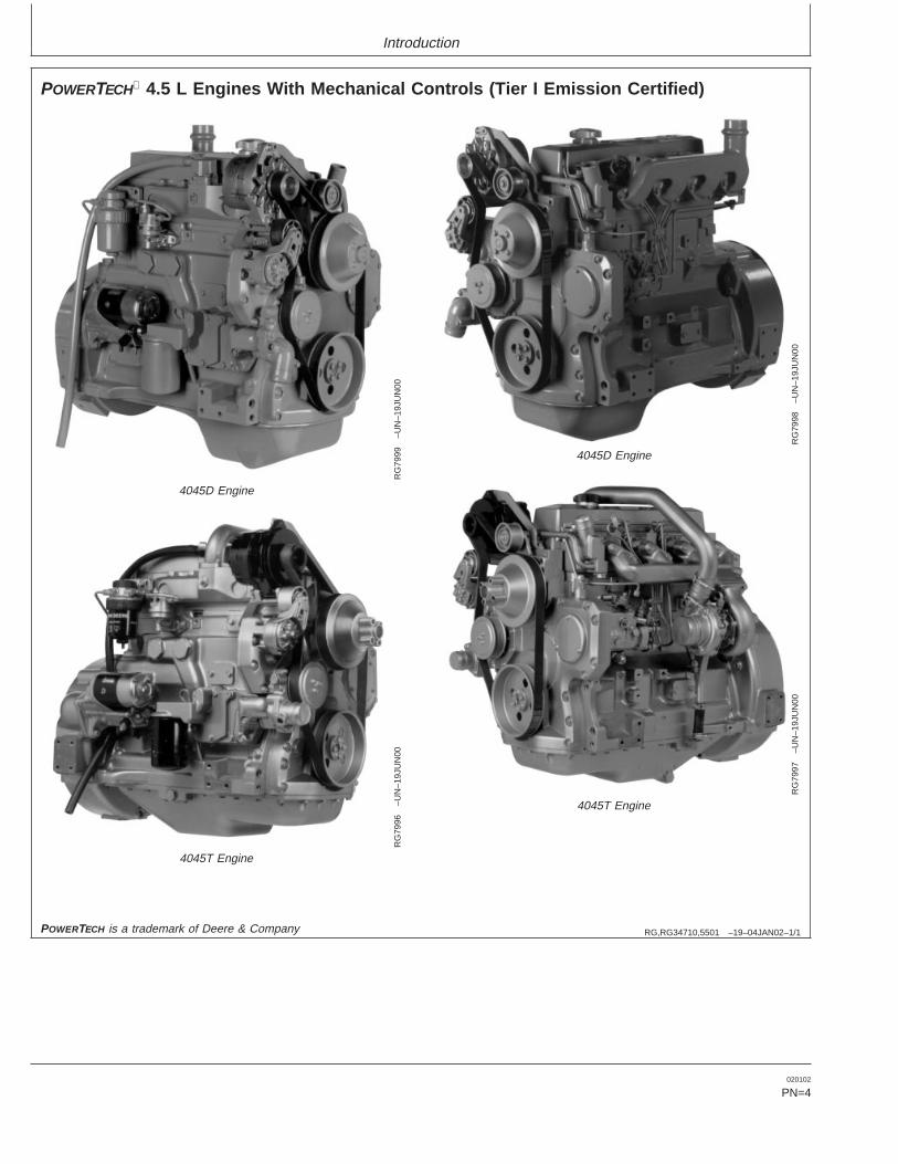
POWERTECH 4.5 L Engines With Mechanical Controls (Tier I Emission Certified)
RG
7999
–UN
–19J
UN
00
4045D Engine
RG
7998
–UN
–19J
UN
00
4045D Engine
RG
7996
–UN
–19J
UN
00
4045T Engine
RG
7997
–UN
–19J
UN
004045T Engine
POWERTECH is a trademark of Deere & Company
020102
PN=4

Introduction
RG,RG34710,5503 –19–04JAN02–1/1
POWERTECH 6.8 L Engines With Mechanical Controls (Tier I Emission Certified)
RG
8003
–UN
–19J
UN
00
6068D Engine
RG
8002
–UN
–19J
UN
00
6068D Engine
RG
8001
–UN
–19J
UN
00
6068T EngineR
G80
00–U
N–1
9JU
N00
6068T Engine
POWERTECH is a trademark of Deere & Company
020102
PN=5

Introduction
020102
PN=6

ContentsPage Page
Record Keeping Generator Set (Standby) Applications. . . . . . . . . 15-9PowerTech Medallion . . . . . . . . . . . . . . . . . . . . . 01-1 Starting the Engine. . . . . . . . . . . . . . . . . . . . . . 15-10Engine Serial Number Plate . . . . . . . . . . . . . . . . 01-1 Warming Engine. . . . . . . . . . . . . . . . . . . . . . . . 15-12Record Engine Serial Number . . . . . . . . . . . . . . 01-2 Normal Engine Operation . . . . . . . . . . . . . . . . . 15-13Engine Option Codes . . . . . . . . . . . . . . . . . . . . . 01-3 Cold Weather Operation. . . . . . . . . . . . . . . . . . 15-14Record Fuel Injection Pump Model Number . . . . 01-5 Changing Engine Speed. . . . . . . . . . . . . . . . . . 15-15
Avoid Excessive Engine Idling . . . . . . . . . . . . . 15-15Stopping the Engine . . . . . . . . . . . . . . . . . . . . . 15-16Safety . . . . . . . . . . . . . . . . . . . . . . . . . . . . . . . . 05-1Using a Booster Battery or Charger . . . . . . . . . 15-17
Fuels, Lubricants, and CoolantLubrication and MaintenanceDiesel Fuel . . . . . . . . . . . . . . . . . . . . . . . . . . . . . 10-1Observe Service Intervals. . . . . . . . . . . . . . . . . . 20-1Lubricity of Diesel Fuel . . . . . . . . . . . . . . . . . . . . 10-2Use Correct Fuels, Lubricants, and Coolant . . . . 20-1Bio-Diesel Fuel . . . . . . . . . . . . . . . . . . . . . . . . . . 10-3Lubrication and Maintenance ServiceHandling And Storing Bio-Diesel Fuel. . . . . . . . . 10-4
Interval Chart—Standard Industrial Engines . . 20-2Diesel Fuel Storage . . . . . . . . . . . . . . . . . . . . . . 10-5Lubrication and Maintenance ServiceDieselscan Fuel Analysis . . . . . . . . . . . . . . . . . . 10-5
Interval Chart—Generator (Standby)Filling Fuel Tank. . . . . . . . . . . . . . . . . . . . . . . . . 10-6Applications . . . . . . . . . . . . . . . . . . . . . . . . . . 20-4Minimizing the Effect of Cold Weather on
Diesel Engines . . . . . . . . . . . . . . . . . . . . . . . . 10-7Lubrication & Maintenance/DailyDiesel Engine Break-In Oil . . . . . . . . . . . . . . . . . 10-8Daily Prestarting Checks . . . . . . . . . . . . . . . . . . 25-1Diesel Engine Oil . . . . . . . . . . . . . . . . . . . . . . . . 10-9
Extended Diesel Engine Oil ServiceIntervals . . . . . . . . . . . . . . . . . . . . . . . . . . . . 10-10 Lubrication & Maintenance/250 Hour/6 Month
Mixing of Lubricants . . . . . . . . . . . . . . . . . . . . . 10-10 Servicing Fire Extinguisher . . . . . . . . . . . . . . . . . 30-1OILSCANand COOLSCAN . . . . . . . . . . . . . . 10-11 Changing Engine Oil and Replacing Filter . . . . . 30-2Alternative and Synthetic Lubricants. . . . . . . . . 10-11 Checking Engine Mounts . . . . . . . . . . . . . . . . . . 30-4Lubricant Storage . . . . . . . . . . . . . . . . . . . . . . . 10-12 Servicing Battery . . . . . . . . . . . . . . . . . . . . . . . . 30-5Grease . . . . . . . . . . . . . . . . . . . . . . . . . . . . . . . 10-12 Manual Belt Tensioner Adjustment . . . . . . . . . . . 30-7Diesel Engine Coolant . . . . . . . . . . . . . . . . . . . 10-13 Manual Belt Tensioner Adjustment UsingDiesel Engine Coolants, Supplemental Belt Tension Tool (Alternate Method
Additive Information . . . . . . . . . . . . . . . . . . . 10-14 For Engines Without Auxiliary Drive). . . . . . . . 30-8Testing Diesel Engine Coolant . . . . . . . . . . . . . 10-15Supplemental Coolant Additives . . . . . . . . . . . . 10-16 Lubrication & Maintenance/500 Hour/12 MonthOperating in Warm Temperature Climates . . . . 10-16 Cleaning Crankcase Vent Tube . . . . . . . . . . . . . 35-1Disposing of Coolant . . . . . . . . . . . . . . . . . . . . 10-17 Checking Air Intake System . . . . . . . . . . . . . . . . 35-2
Replacing Fuel Filter Element. . . . . . . . . . . . . . . 35-3Checking Belt Tensioner Spring TensionEngine Operating Guidelines
Instrument (Gauge) Panels. . . . . . . . . . . . . . . . . 15-1 and Belt Wear (Automatic Tensioner) . . . . . . . 35-4Checking Engine Electrical GroundInstrument (Gauge) Panel (North America). . . . . 15-2
VDO Instrument (Gauge) Panel (Except Connections . . . . . . . . . . . . . . . . . . . . . . . . . . 35-7Checking Cooling System. . . . . . . . . . . . . . . . . . 35-7North America) . . . . . . . . . . . . . . . . . . . . . . . . 15-4
Engine Break-In Service. . . . . . . . . . . . . . . . . . . 15-6Continued on next pageAuxiliary Gear Drive Limitations . . . . . . . . . . . . . 15-9
All information, illustrations and specifications in this manual are based onthe latest information available at the time of publication. The right isreserved to make changes at any time without notice.
COPYRIGHT 2002DEERE & COMPANY
Moline, IllinoisAll rights reserved
A John Deere ILLUSTRUCTION ManualPrevious Editions
Copyright 1996, 2000
i 020102
PN=1
Contents
Page Page
Replenishing Supplemental Coolant Engine Crankcase Oil Fill Quantities . . . . . . . . . 60-8Unified Inch Bolt and Cap Screw TorqueAdditives (SCAs) Between Coolant
Changes . . . . . . . . . . . . . . . . . . . . . . . . . . . . . 35-8 Values. . . . . . . . . . . . . . . . . . . . . . . . . . . . . . 60-12Metric Bolt and Cap Screw Torque Values . . . . 60-13Testing Diesel Engine Coolant . . . . . . . . . . . . . 35-10
Pressure Testing Cooling System. . . . . . . . . . . 35-11Lubrication and Maintenance RecordsUsing Lubrication and Maintenance Records . . . 65-1Lubrication & Maint./2000 Hour/24 MonthDaily (Prestarting) Service . . . . . . . . . . . . . . . . . 65-1Adjusting Variable Speed (Droop) on250 Hour/6 Month Service . . . . . . . . . . . . . . . . . 65-2Generator Set Engines . . . . . . . . . . . . . . . . . . 40-1500 Hour/12 Month Service . . . . . . . . . . . . . . . . 65-3Checking Crankshaft Vibration Damper2000 Hour/24 Month Service . . . . . . . . . . . . . . . 65-4(6-Cylinder Engine Only). . . . . . . . . . . . . . . . . 40-3Service as Required . . . . . . . . . . . . . . . . . . . . . . 65-5Flushing Cooling System . . . . . . . . . . . . . . . . . . 40-4
Testing Thermostats Opening Temperature . . . . 40-7Emission System WarrantyCheck and Adjust Valve Clearance . . . . . . . . . 40-10U.S. EPA Emissions Control Warranty
Statement . . . . . . . . . . . . . . . . . . . . . . . . . . . . 70-1Service as RequiredEmissions Control System Certification Label. . . 70-2Additional Service Information . . . . . . . . . . . . . . 45-1
Do Not Modify Fuel System . . . . . . . . . . . . . . . . 45-1Adding Coolant. . . . . . . . . . . . . . . . . . . . . . . . . . 45-2Replacing Single Stage Air Cleaner . . . . . . . . . . 45-3Replacing Axial Seal Air Cleaner Filter
Element . . . . . . . . . . . . . . . . . . . . . . . . . . . . . 45-4Replacing Radial Seal Air Cleaner Filter
Element . . . . . . . . . . . . . . . . . . . . . . . . . . . . . 45-6Replacing Fan and Alternator Belts . . . . . . . . . . 45-8Checking Fuses In Instrument Panels . . . . . . . . 45-9Bleeding the Fuel System. . . . . . . . . . . . . . . . . 45-10
TroubleshootingGeneral Troubleshooting Information . . . . . . . . . 50-1Engine Wiring Diagram Legend
(Standard Instrument Panel For NorthAmerica) . . . . . . . . . . . . . . . . . . . . . . . . . . . . . 50-3
Wiring Diagram (Standard InstrumentPanel For North America) . . . . . . . . . . . . . . . . 50-4
Engine Wiring Diagram—VDOInstrument Panel (Except North America) . . . . 50-5
Engine Wiring Diagram Legend—VDOInstrument Panel (Except North America) . . . . 50-6
Engine Troubleshooting . . . . . . . . . . . . . . . . . . . 50-7
StorageEngine Storage Guidelines . . . . . . . . . . . . . . . . . 55-1Preparing Engine for Long Term Storage . . . . . . 55-2Removing Engine from Long Term Storage . . . . 55-3
SpecificationsGeneral OEM Engine Specifications—4.5 L
Engines. . . . . . . . . . . . . . . . . . . . . . . . . . . . . . 60-1General OEM Engine Specifications—6.8 L
Engines. . . . . . . . . . . . . . . . . . . . . . . . . . . . . . 60-2Engine Power Ratings And Fuel Injection
Pump Specifications . . . . . . . . . . . . . . . . . . . . 60-3
ii 020102
PN=2
Record Keeping
RG,RG34710,5505 –19–04JAN02–1/1
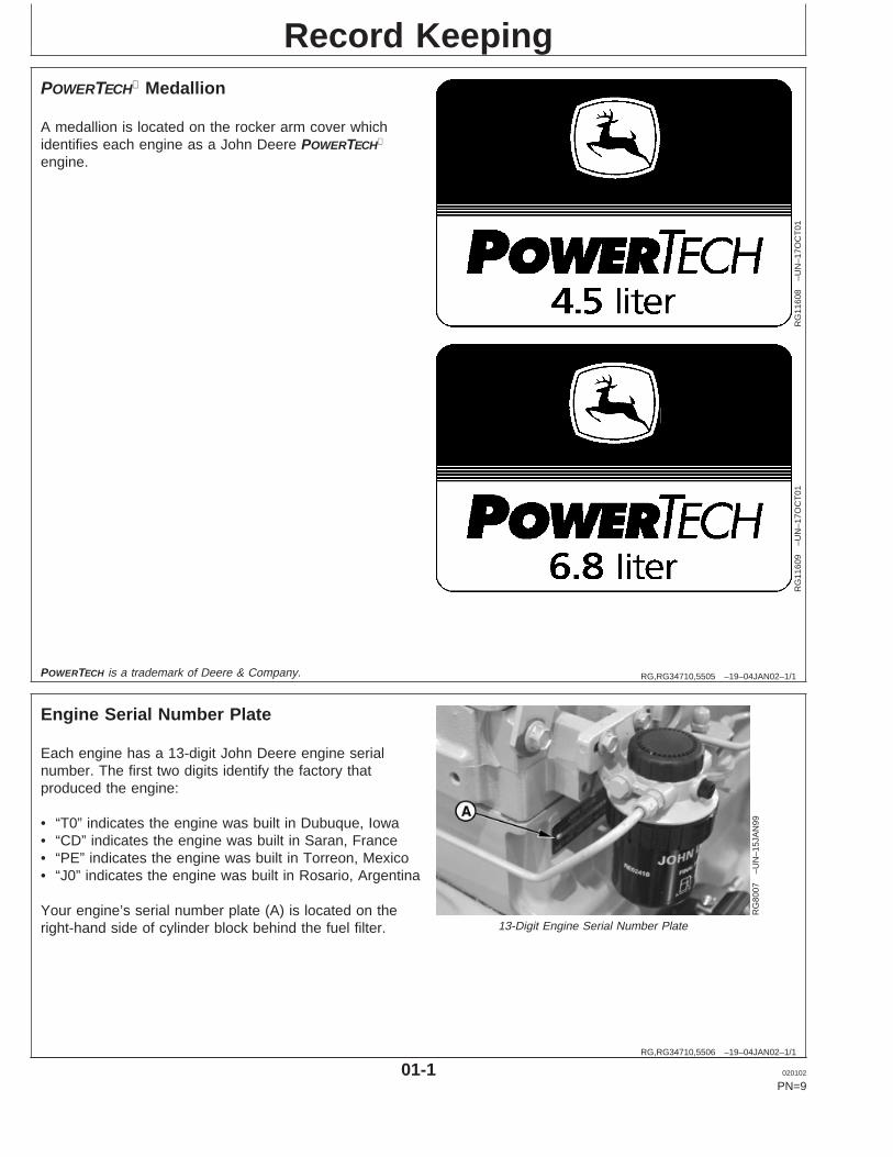
POWERTECH Medallion
RG
1160
8–U
N–1
7OC
T01
RG
1160
9–U
N–1
7OC
T01
A medallion is located on the rocker arm cover whichidentifies each engine as a John Deere POWERTECH
engine.
POWERTECH is a trademark of Deere & Company.
RG,RG34710,5506 –19–04JAN02–1/1
Engine Serial Number Plate
RG
8007
–UN
–15J
AN
99
13-Digit Engine Serial Number Plate
Each engine has a 13-digit John Deere engine serialnumber. The first two digits identify the factory thatproduced the engine:
• “T0” indicates the engine was built in Dubuque, Iowa• “CD” indicates the engine was built in Saran, France• “PE” indicates the engine was built in Torreon, Mexico• “J0” indicates the engine was built in Rosario, Argentina
Your engine’s serial number plate (A) is located on theright-hand side of cylinder block behind the fuel filter.
01-1 020102
PN=9
Record Keeping
RG,RG34710,5507 –19–04JAN02–1/1
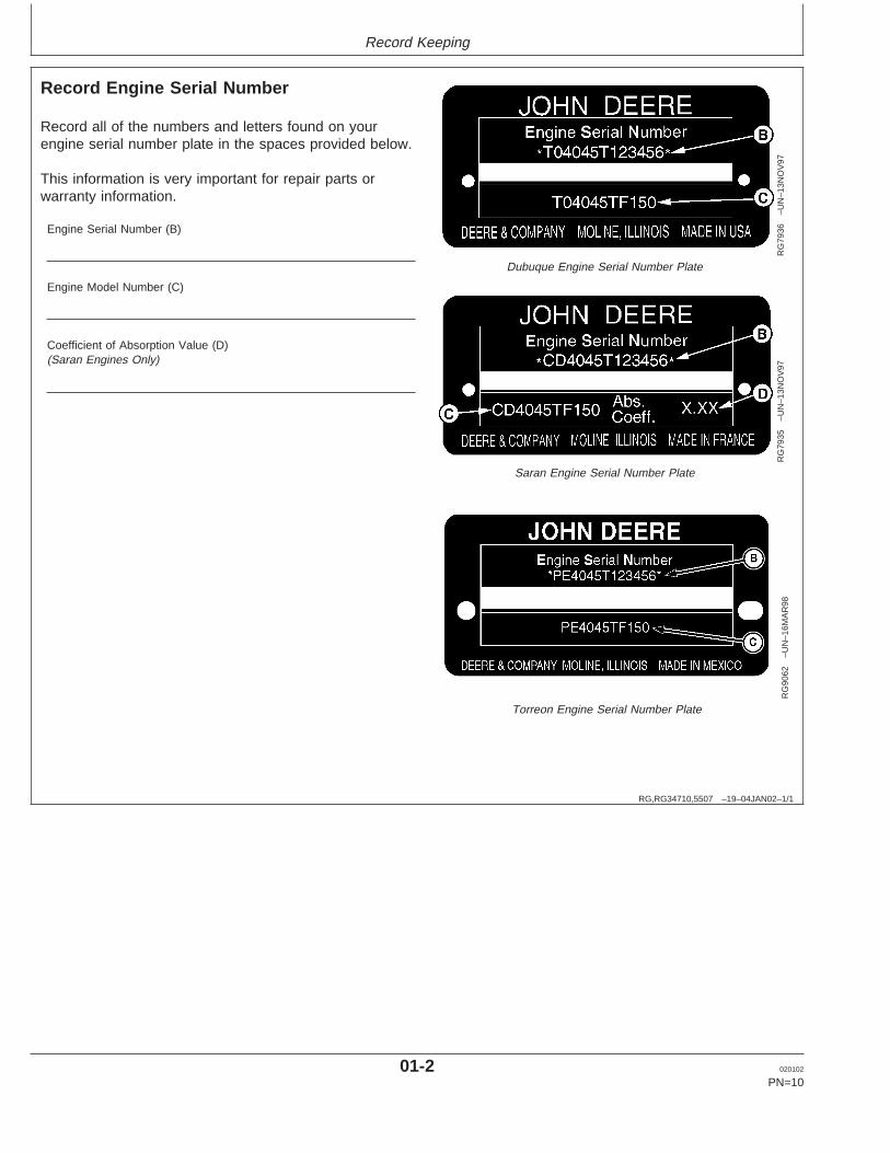
Record Engine Serial Number
RG
7936
–UN
–13N
OV
97
Dubuque Engine Serial Number Plate
RG
7935
–UN
–13N
OV
97
Saran Engine Serial Number Plate
RG
9062
–UN
–16M
AR
98
Torreon Engine Serial Number Plate
Record all of the numbers and letters found on yourengine serial number plate in the spaces provided below.
This information is very important for repair parts orwarranty information.
Engine Serial Number (B)
Engine Model Number (C)
Coefficient of Absorption Value (D)(Saran Engines Only)
01-2 020102
PN=10
Record Keeping
RG,RG34710,5508 –19–04JAN02–1/2
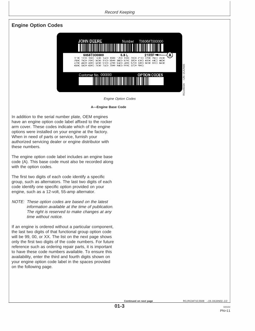
Engine Option Codes
RG
1060
3A–U
N–1
5JU
N00
Engine Option Codes
A—Engine Base Code
In addition to the serial number plate, OEM engineshave an engine option code label affixed to the rockerarm cover. These codes indicate which of the engineoptions were installed on your engine at the factory.When in need of parts or service, furnish yourauthorized servicing dealer or engine distributor withthese numbers.
The engine option code label includes an engine basecode (A). This base code must also be recorded alongwith the option codes.
The first two digits of each code identify a specificgroup, such as alternators. The last two digits of eachcode identify one specific option provided on yourengine, such as a 12-volt, 55-amp alternator.
NOTE: These option codes are based on the latestinformation available at the time of publication.The right is reserved to make changes at anytime without notice.
If an engine is ordered without a particular component,the last two digits of that functional group option codewill be 99, 00, or XX. The list on the next page showsonly the first two digits of the code numbers. For futurereference such as ordering repair parts, it is importantto have these code numbers available. To ensure thisavailability, enter the third and fourth digits shown onyour engine option code label in the spaces providedon the following page.
01-3 020102
PN=11
Continued on next page

Record Keeping
RG,RG34710,5508 –19–04JAN02–2/2
NOTE: Your engine option code label may not containall option codes if an option has been addedafter the engine left the producing factory.
If option code label is lost or destroyed,consult your servicing dealer or enginedistributor selling the engine for a replacement.
An additional option code label may also bedelivered with the engine. Place this sticker ortag, for reference, either on this page or in theengine owner’s warranty booklet underOPTION CODES title.
Option Codes Description Option Codes Description11 Rocker Arm Cover 45 Balancer Shafts12 Oil Fill Inlet 46 Cylinder Block With Liners and Camshaft13 Crankshaft Pulley 47 Crankshaft and Bearings14 Flywheel Housing 48 Connecting Rods and Pistons15 Flywheel 49 Valve Actuating Mechanism16 Fuel Injection Pump 50 Oil Pump17 Air Inlet 51 Cylinder Head With Valves18 Air Cleaner 52 Auxiliary Gear Drive19 Oil Pan 55 Shipping Stand20 Coolant Pump 56 Paint Option21 Thermostat Cover 57 Coolant Pump Inlet22 Thermostat 59 Oil Cooler23 Fan Drive 60 Add-on Auxiliary Drive Pulley24 Fan Belt 62 Alternator Mounting Bracket25 Fan 64 Exhaust Elbow26 Engine Coolant Heater 65 Turbocharger27 Radiator 66 Temperature Switch28 Exhaust Manifold 67 Electronic Tachometer Sensor29 Ventilator System 68 Crankshaft Rear Damper30 Starter Motor 69 Engine Serial Number Plate31 Alternator 74 Air Conditioning (Freon) Compressor32 Instrument Panel 75 Air Restriction Indicator33 Tachometer 76 Oil Pressure Switch35 Fuel Filters 78 Air Compressor36 Front Plate 81 Water Separator37 Fuel Transfer Pump 86 Fan Pulley39 Thermostat Housing 87 Belt Tensioner40 Oil Dipstick 88 Oil Filter41 Belt-Driven Front Auxiliary Drive 95 Special Equipment (Factory Installed)43 Starting Aid 97 Special Equipment (Field Installed)44 Timing Gear Cover With Gears 98 Shipping
99 Service Only Items
Engine Base Code
01-4 020102
PN=12
Record Keeping
RG,RG34710,5511 –19–20MAY96–1/1
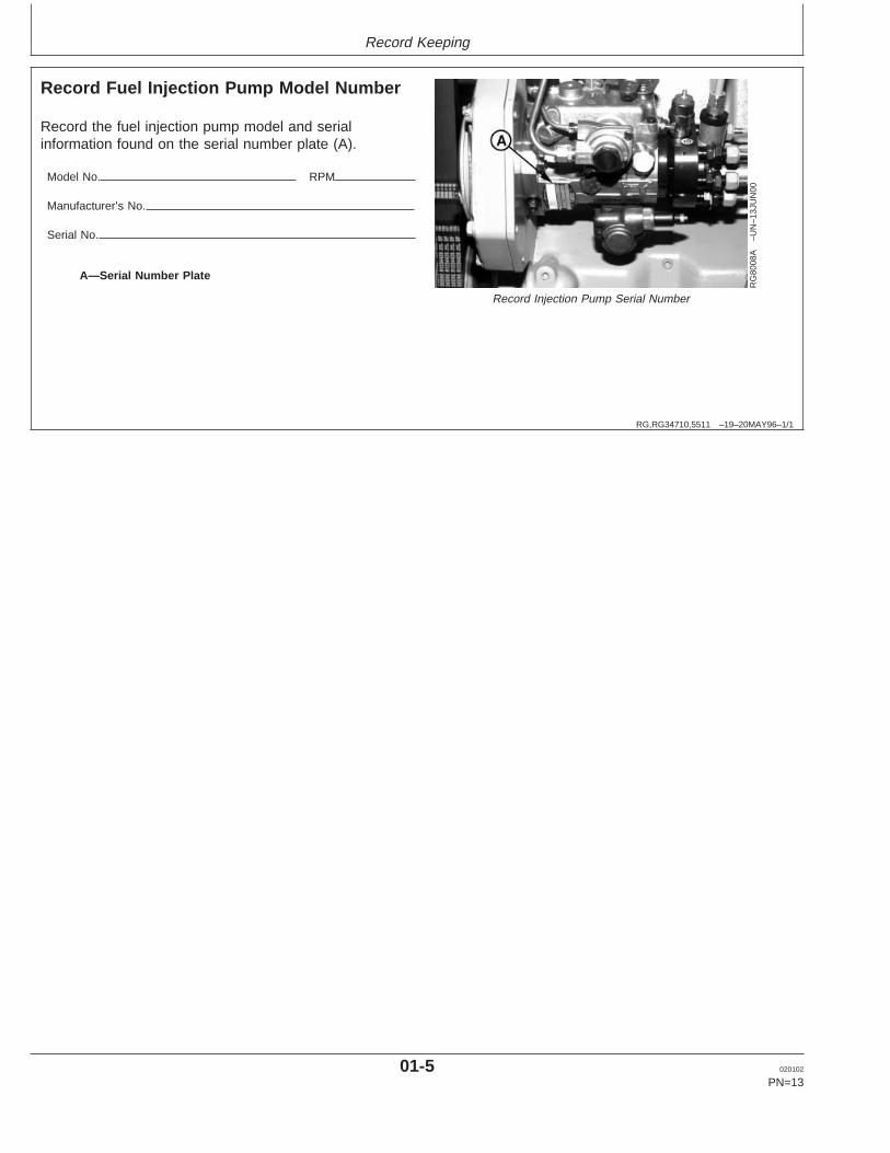
Record Fuel Injection Pump Model Number
RG
8008
A–U
N–1
3JU
N00
Record Injection Pump Serial Number
A—Serial Number Plate
Record the fuel injection pump model and serialinformation found on the serial number plate (A).
Model No. RPM
Manufacturer’s No.
Serial No.
01-5 020102
PN=13
Safety
DX,ALERT –19–29SEP98–1/1
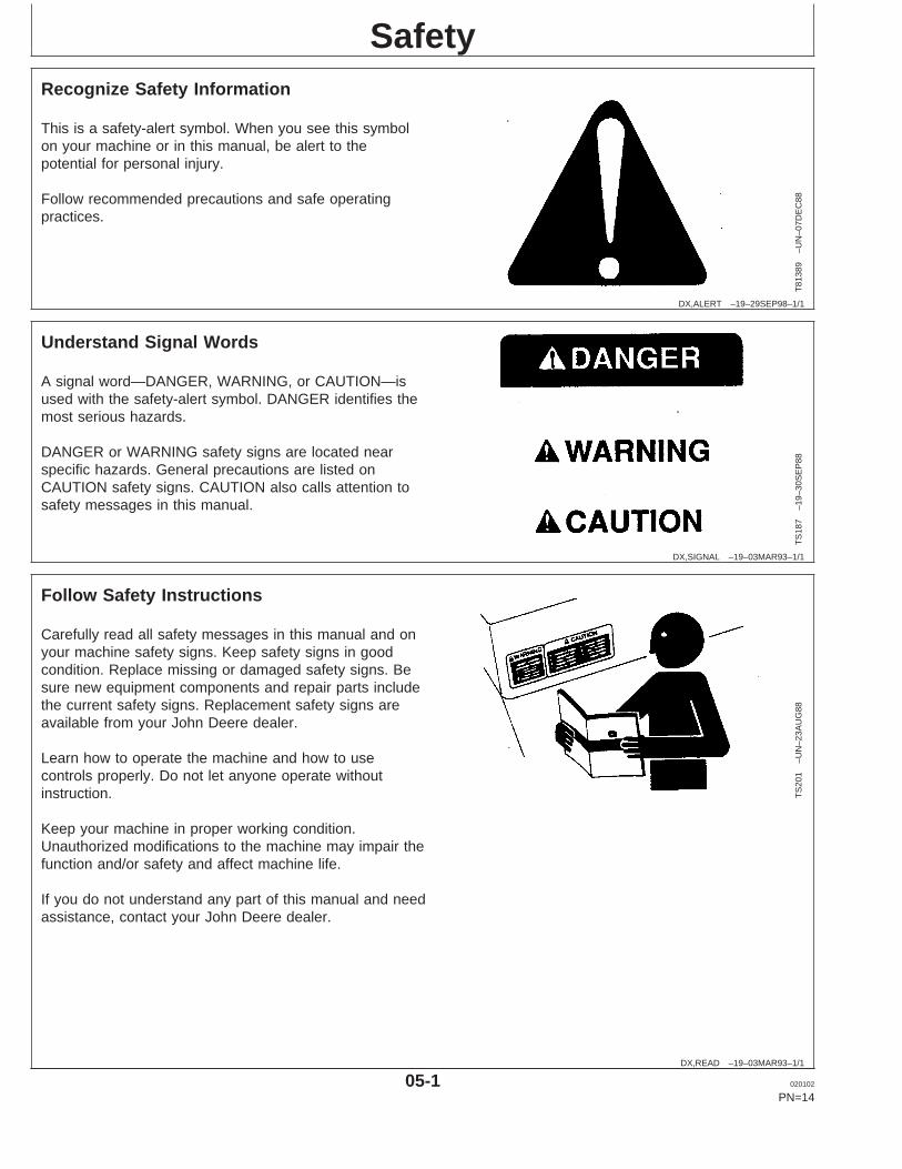
Recognize Safety Information
T81
389
–UN
–07D
EC
88
This is a safety-alert symbol. When you see this symbolon your machine or in this manual, be alert to thepotential for personal injury.
Follow recommended precautions and safe operatingpractices.
DX,SIGNAL –19–03MAR93–1/1
Understand Signal Words
TS
187
–19–
30S
EP
88
A signal word—DANGER, WARNING, or CAUTION—isused with the safety-alert symbol. DANGER identifies themost serious hazards.
DANGER or WARNING safety signs are located nearspecific hazards. General precautions are listed onCAUTION safety signs. CAUTION also calls attention tosafety messages in this manual.
DX,READ –19–03MAR93–1/1
Follow Safety Instructions
TS
201
–UN
–23A
UG
88
Carefully read all safety messages in this manual and onyour machine safety signs. Keep safety signs in goodcondition. Replace missing or damaged safety signs. Besure new equipment components and repair parts includethe current safety signs. Replacement safety signs areavailable from your John Deere dealer.
Learn how to operate the machine and how to usecontrols properly. Do not let anyone operate withoutinstruction.
Keep your machine in proper working condition.Unauthorized modifications to the machine may impair thefunction and/or safety and affect machine life.
If you do not understand any part of this manual and needassistance, contact your John Deere dealer.
05-1 020102
PN=14

Safety
DX,SIGNS1 –19–04JUN90–1/1
Replace Safety Signs
TS
201
–UN
–23A
UG
88
Replace missing or damaged safety signs. See themachine operator’s manual for correct safety signplacement.
RG,RG34710,7508 –19–30JUN97–1/1
Prevent Bypass Starting
RG
5419
–UN
–28F
EB
89
Avoid possible injury or death from engine runaway.
Do not start engine by shorting across starter terminal.Engine will start with PTO engaged if normal circuitry isbypassed.
Start engine only from operator’s station with PTOdisengaged or in neutral.
DX,FIRE1 –19–03MAR93–1/1
Handle Fuel Safely—Avoid Fires
TS
202
–UN
–23A
UG
88
Handle fuel with care: it is highly flammable. Do not refuelthe machine while smoking or when near open flame orsparks.
Always stop engine before refueling machine. Fill fuel tankoutdoors.
Prevent fires by keeping machine clean of accumulatedtrash, grease, and debris. Always clean up spilled fuel.
05-2 020102
PN=15

Safety
DX,FIRE2 –19–03MAR93–1/1
Prepare for Emergencies
TS
291
–UN
–23A
UG
88
Be prepared if a fire starts.
Keep a first aid kit and fire extinguisher handy.
Keep emergency numbers for doctors, ambulance service,hospital, and fire department near your telephone.
DX,FIRE3 –19–16APR92–1/1
Handle Starting Fluid Safely
TS
1356
–UN
–18M
AR
92
Starting fluid is highly flammable.
Keep all sparks and flame away when using it. Keepstarting fluid away from batteries and cables.
To prevent accidental discharge when storing thepressurized can, keep the cap on the container, and storein a cool, protected location.
Do not incinerate or puncture a starting fluid container.
DX,FLAME –19–29SEP98–1/1
Handle Fluids Safely—Avoid Fires
TS
227
–UN
–23A
UG
88
When you work around fuel, do not smoke or work nearheaters or other fire hazards.
Store flammable fluids away from fire hazards. Do notincinerate or puncture pressurized containers.
Make sure engine is clean of trash, grease, and debris.
Do not store oily rags; they can ignite and burnspontaneously.
05-3 020102
PN=16

Safety
DX,LOOSE –19–04JUN90–1/1
Service Engines Safely
TS
228
–UN
–23A
UG
88
Tie long hair behind your head. Do not wear a necktie,scarf, loose clothing, or necklace when you work nearengine tools or moving parts. If these items were to getcaught, severe injury could result.
Remove rings and other jewelry to prevent electricalshorts and entanglement in moving parts.
DX,WEAR –19–10SEP90–1/1
Wear Protective Clothing
TS
206
–UN
–23A
UG
88
Wear close fitting clothing and safety equipmentappropriate to the job.
Prolonged exposure to loud noise can cause impairmentor loss of hearing.
Wear a suitable hearing protective device such asearmuffs or earplugs to protect against objectionable oruncomfortable loud noises.
Operating equipment safely requires the full attention ofthe operator. Do not wear radio or music headphoneswhile operating machine.
DX,NOISE –19–03MAR93–1/1
Protect Against Noise
TS
207
–UN
–23A
UG
88
Prolonged exposure to loud noise can cause impairmentor loss of hearing.
Wear a suitable hearing protective device such asearmuffs or earplugs to protect against objectionable oruncomfortable loud noises.
05-4 020102
PN=17

Safety
DX,MSDS,NA –19–03MAR93–1/1
Handle Chemical Products Safely
TS
1132
–UN
–26N
OV
90
Direct exposure to hazardous chemicals can causeserious injury. Potentially hazardous chemicals used withJohn Deere equipment include such items as lubricants,coolants, paints, and adhesives.
A Material Safety Data Sheet (MSDS) provides specificdetails on chemical products: physical and health hazards,safety procedures, and emergency response techniques.
Check the MSDS before you start any job using ahazardous chemical. That way you will know exactly whatthe risks are and how to do the job safely. Then followprocedures and recommended equipment.
(See your John Deere dealer for MSDS’s on chemicalproducts used with John Deere equipment.)
DX,PTO –19–12SEP95–1/1
Stay Clear of Rotating Drivelines
TS
1644
–UN
–22A
UG
95
Entanglement in rotating driveline can cause serious injuryor death.
Keep master shield and driveline shields in place at alltimes. Make sure rotating shields turn freely.
Wear close fitting clothing. Stop the engine and be surePTO driveline is stopped before making adjustments,connections, or cleaning out PTO driven equipment.
05-5 020102
PN=18

Safety
DX,SERV –19–17FEB99–1/1
Practice Safe Maintenance
TS
218
–UN
–23A
UG
88
Understand service procedure before doing work. Keeparea clean and dry.
Never lubricate, service, or adjust machine while it ismoving. Keep hands, feet, and clothing from power-drivenparts. Disengage all power and operate controls to relievepressure. Lower equipment to the ground. Stop theengine. Remove the key. Allow machine to cool.
Securely support any machine elements that must beraised for service work.
Keep all parts in good condition and properly installed. Fixdamage immediately. Replace worn or broken parts.Remove any buildup of grease, oil, or debris.
On self-propelled equipment, disconnect battery groundcable (-) before making adjustments on electrical systemsor welding on machine.
On towed implements, disconnect wiring harnesses fromtractor before servicing electrical system components orwelding on machine.
DX,AIR –19–17FEB99–1/1
Work In Ventilated Area
TS
220
–UN
–23A
UG
88
Engine exhaust fumes can cause sickness or death. If it isnecessary to run an engine in an enclosed area, removethe exhaust fumes from the area with an exhaust pipeextension.
If you do not have an exhaust pipe extension, open thedoors and get outside air into the area
05-6 020102
PN=19
Safety
DX,FLUID –19–03MAR93–1/1
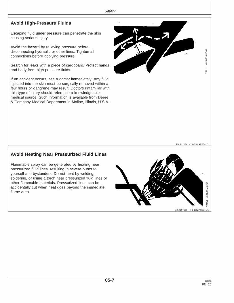
Avoid High-Pressure Fluids
X98
11–U
N–2
3AU
G88
Escaping fluid under pressure can penetrate the skincausing serious injury.
Avoid the hazard by relieving pressure beforedisconnecting hydraulic or other lines. Tighten allconnections before applying pressure.
Search for leaks with a piece of cardboard. Protect handsand body from high pressure fluids.
If an accident occurs, see a doctor immediately. Any fluidinjected into the skin must be surgically removed within afew hours or gangrene may result. Doctors unfamiliar withthis type of injury should reference a knowledgeablemedical source. Such information is available from Deere& Company Medical Department in Moline, Illinois, U.S.A.
DX,TORCH –19–03MAR93–1/1
Avoid Heating Near Pressurized Fluid Lines
TS
953
–UN
–15M
AY
90
Flammable spray can be generated by heating nearpressurized fluid lines, resulting in severe burns toyourself and bystanders. Do not heat by welding,soldering, or using a torch near pressurized fluid lines orother flammable materials. Pressurized lines can beaccidentally cut when heat goes beyond the immediateflame area.
05-7 020102
PN=20

Safety
DX,PAINT –19–19JUL01–1/1
Remove Paint Before Welding or Heating
TS
220
–UN
–23A
UG
88
Avoid potentially toxic fumes and dust.
Hazardous fumes can be generated when paint is heatedby welding, soldering, or using a torch.
Remove paint before heating:
• Remove paint a minimum of 76 mm (3 in.) from area tobe affected by heating.
• If you sand or grind paint, avoid breathing the dust.Wear an approved respirator.
• If you use solvent or paint stripper, remove stripper withsoap and water before welding. Remove solvent orpaint stripper containers and other flammable materialfrom area. Allow fumes to disperse at least 15 minutesbefore welding or heating.
Do not use a chlorinated solvent in areas where weldingwill take place.
Do all work in an area that is well ventilated to carry toxicfumes and dust away.
Dispose of paint and solvent properly.
DX,RCAP –19–04JUN90–1/1
Service Cooling System Safely
TS
281
–UN
–23A
UG
88
Explosive release of fluids from pressurized coolingsystem can cause serious burns.
Shut off engine. Only remove filler cap when cool enoughto touch with bare hands. Slowly loosen cap to first stopto relieve pressure before removing completely.
05-8 020102
PN=21
Safety
DX,DUST –19–15MAR91–1/1
Avoid Harmful Asbestos Dust
TS
220
–UN
–23A
UG
88
Avoid breathing dust that may be generated whenhandling components containing asbestos fibers. Inhaledasbestos fibers may cause lung cancer.
Components in products that may contain asbestos fibersare brake pads, brake band and lining assemblies, clutchplates, and some gaskets. The asbestos used in thesecomponents is usually found in a resin or sealed in someway. Normal handling is not hazardous as long asairborne dust containing asbestos is not generated.
Avoid creating dust. Never use compressed air forcleaning. Avoid brushing or grinding material containingasbestos. When servicing, wear an approved respirator. Aspecial vacuum cleaner is recommended to cleanasbestos. If not available, apply a mist of oil or water onthe material containing asbestos.
Keep bystanders away from the area.
DX,SPARKS –19–03MAR93–1/1
Prevent Battery Explosions
TS
204
–UN
–23A
UG
88
Keep sparks, lighted matches, and open flame away fromthe top of battery. Battery gas can explode.
Never check battery charge by placing a metal objectacross the posts. Use a volt-meter or hydrometer.
Do not charge a frozen battery; it may explode. Warmbattery to 16°C (60°F).
05-9 020102
PN=22

Safety
DX,POISON –19–21APR93–1/1
Prevent Acid Burns
TS
203
–UN
–23A
UG
88
Sulfuric acid in battery electrolyte is poisonous. It is strongenough to burn skin, eat holes in clothing, and causeblindness if splashed into eyes.
Avoid the hazard by:
1. Filling batteries in a well-ventilated area.2. Wearing eye protection and rubber gloves.3. Avoiding breathing fumes when electrolyte is added.4. Avoiding spilling or dripping electrolyte.5. Use proper jump start procedure.
If you spill acid on yourself:
1. Flush your skin with water.2. Apply baking soda or lime to help neutralize the acid.3. Flush your eyes with water for 15—30 minutes. Get
medical attention immediately.
If acid is swallowed:
1. Do not induce vomiting.2. Drink large amounts of water or milk, but do not
exceed 2 L (2 quarts).3. Get medical attention immediately.
DX,SPRAY –19–16APR92–1/1
Protect Against High Pressure Spray
TS
1343
–UN
–18M
AR
92
Spray from high pressure nozzles can penetrate the skinand cause serious injury. Keep spray from contactinghands or body.
If an accident occurs, see a doctor immediately. Any highpressure spray injected into the skin must be surgicallyremoved within a few hours or gangrene may result.Doctors unfamiliar with this type of injury should referencea knowledgeable medical source. Such information isavailable from Deere & Company Medical Department inMoline, Illinois, U.S.A.
05-10 020102
PN=23

Safety
DX,DRAIN –19–03MAR93–1/1
Dispose of Waste Properly
TS
1133
–UN
–26N
OV
90
Improperly disposing of waste can threaten theenvironment and ecology. Potentially harmful waste usedwith John Deere equipment include such items as oil, fuel,coolant, brake fluid, filters, and batteries.
Use leakproof containers when draining fluids. Do not usefood or beverage containers that may mislead someoneinto drinking from them.
Do not pour waste onto the ground, down a drain, or intoany water source.
Air conditioning refrigerants escaping into the air candamage the Earth’s atmosphere. Government regulationsmay require a certified air conditioning service center torecover and recycle used air conditioning refrigerants.
Inquire on the proper way to recycle or dispose of wastefrom your local environmental or recycling center, or fromyour John Deere dealer.
05-11 020102
PN=24
Fuels, Lubricants, and Coolant
OUOD002,0000171 –19–18DEC01–1/1
Diesel Fuel
Consult your local fuel distributor for properties of thediesel fuel available in your area.
In general, diesel fuels are blended to satisfy the lowtemperature requirements of the geographical area inwhich they are marketed.
Diesel fuels specified to EN 590 or ASTM D975 arerecommended.
Required fuel properties
In all cases, the fuel must meet the followingproperties:
Cetane number of 45 minimum. Cetane numbergreater than 50 is preferred, especially fortemperatures below -20°C (-4°F) or elevations above1500 m (5000 ft).
Cold Filter Plugging Point (CFPP) below theexpected low temperature OR Cloud Point at least5°C (9°F) below the expected low temperature.
Fuel lubricity should pass a minimum load level of3100 grams as measured by ASTM D6078 or,maximum scar diameter of 0.45 mm as measured byASTM D6079.
Sulfur content:
• Diesel fuel quality and fuel sulfur content mustcomply with all existing regulations for the area inwhich the engine operates.
• Sulfur content less than 0.05% (500 ppm) ispreferred.
• If diesel fuel with sulfur content greater than 0.05%(500 ppm) is used, crankcase oil service intervalsmay be affected. (See recommendation for DieselEngine Oil.)
• DO NOT use diesel fuel with sulfur content greaterthan 1.0%.
IMPORTANT: DO NOT mix used engine oil or anyother type of lubricating oil withdiesel fuel.
10-1 020102
PN=25
Fuels, Lubricants, and Coolant
OUOD002,0000179 –19–18DEC01–1/1
Lubricity of Diesel Fuel
Diesel fuel must have adequate lubricity to ensureproper operation and durability of fuel injection systemcomponents.
Diesel fuels for highway use in the United States andCanada require sulfur content less than 0.05% (500ppm).
Diesel fuel in the European Union requires sulfurcontent less than 0.05% (500 ppm).
Experience shows that some low sulfur diesel fuelsmay have inadequate lubricity and their use mayreduce performance in fuel injection systems due toinadequate lubrication of injection pump components.The lower concentration of aromatic compounds inthese fuels also adversely affects injection pump sealsand may result in leaks.
Use of low lubricity diesel fuels may also causeaccelerated wear, injection nozzle erosion or corrosion,engine speed instability, hard starting, low power, andengine smoke.
Fuel lubricity should pass a minimum load level of3100 gram as measured by the ASTM D6078 ormaximum scar diameter of 0.45 mm as measured byASTM D6079.
ASTM D975 and EN 590 specifications do not requirefuels to pass a fuel lubricity test.
If fuel of low or unknown lubricity is used, add JohnDeere PREMIUM DIESEL FUEL CONDITIONER (orequivalent) at the specified concentration.
10-2 020102
PN=26

Fuels, Lubricants, and Coolant
RG41183,0000046 –19–18DEC01–1/1
Bio-Diesel Fuel
Consult your local fuel distributor for properties of thebio-diesel fuel available in your area.
Bio-diesel fuels may be used ONLY if the bio-dieselfuel properties meet the latest edition of ASTM PS121,DIN 51606 or equivalent specification.
It has been found that bio-diesel fuels may improvelubricity in concentrations up to a 5% blend inpetroleum diesel fuel.
When using a blend of bio-diesel fuel, the engine oillevel must be checked daily when the air temperatureis -10°C (14°F) or lower. If the oil becomes diluted withfuel, shorten oil change intervals accordingly.
IMPORTANT: Raw pressed vegetable oils are NOTacceptable for use for fuel in anyconcentration in John Deereengines.
These oils do not burn completely,and will cause engine failure byleaving deposits on injectors and inthe combustion chamber.
A major environmental benefit of bio-diesel fuel is itsability to biodegrade. This makes proper storage andhandling of bio-diesel fuel especially important. Areasof concern include:
• Quality of new fuel• Water content of the fuel• Problems due to aging of the fuel
Potential problems resulting from deficiencies in theabove areas when using bio-diesel fuel inconcentrations above 5% may lead to the followingsymptoms:
• Power loss and deterioration of performance• Fuel leakage• Corrosion of fuel injection equipment• Coked and/or blocked injector nozzles, resulting in
engine misfire• Filter plugging• Lacquering and/or seizure of internal components• Sludge and sediments• Reduced service life of engine components
10-3 020102
PN=27

Fuels, Lubricants, and Coolant
OUOD002,0000176 –19–18DEC01–1/1
Handling And Storing Bio-Diesel Fuel
CAUTION: Handle fuel carefully. Do not fillthe fuel tank when engine is running.
DO NOT smoke while you fill the fuel tank orservice the fuel system.
Fill the fuel tank at the end of each day’s operation toprevent water condensation and freezing during coldweather.
Keep all storage tanks as full as practicable tominimize condensation.
Ensure that all fuel tank caps and covers are installedproperly to prevent moisture from entering.
Monitor water content of the fuel regularly.
Fuel filter may require more frequent replacement dueto premature plugging.
Check engine oil level daily prior to starting engine. Arising oil level may indicate fuel dilution of the engineoil.
IMPORTANT: The fuel tank is vented through thefiller cap. If a new filler cap isrequired, always replace it with anoriginal vented cap.
When fuel is stored for an extended period or if thereis a slow turnover of fuel, add a fuel conditioner tostabilize the fuel and prevent water condensation.Contact your fuel supplier for recommendations.
10-4 020102
PN=28

Fuels, Lubricants, and Coolant
RG,RG34710,7526 –19–18DEC01–1/1
Diesel Fuel Storage
CAUTION: Handle fuel carefully. Do not fillthe fuel tank when engine is running.
DO NOT smoke while you fill the fuel tank orservice the fuel system.
Fill the fuel tank at the end of each day’s operation toprevent water condensation and freezing during coldweather.
IMPORTANT: DO NOT store diesel fuel ingalvanized containers. Diesel fuelstored in galvanized containersreacts with zinc coating on containerto form zinc flakes. If fuel containswater, a zinc gel will also form. Thegel and flakes will quickly plug fuelfilters, damage injection nozzles andinjection pump.
DO NOT use brass-coated containersfor fuel storage. Brass is an alloy ofcopper and zinc.
Store diesel fuel in plastic, aluminum, and steelcontainers specially coated for diesel fuel storage.
Avoid storing fuel over long periods of time. If fuel isstored for more than a month prior to use, or there is aslow turnover in fuel tank or supply tank, add a fuelconditioner such as John Deere PREMIUM DIESELFUEL CONDITIONER or equivalent to stabilize the fueland prevent water condensation. John DeerePREMIUM DIESEL FUEL CONDITIONER is availablein winter and summer formulas. Fuel conditioner alsoreduces fuel gelling and controls wax separation duringcold weather.
IMPORTANT: The fuel tank is vented through thefiller cap. If a new filler cap isrequired, always replace with anoriginal vented cap.
DX,FUEL6 –19–06DEC00–1/1
Dieselscan Fuel Analysis
DIESELSCAN is a John Deere fuel sampling program tohelp you monitor the quality of your fuel source. It verifiesfuel type, cleanliness, water content, suitability for coldweather operation, and if fuel is within ASTMspecifications. Check with your John Deere dealer foravailability of DIESELSCAN kits.
DIESELSCAN is a trademark of Deere & Company
10-5 020102
PN=29

Fuels, Lubricants, and Coolant
RG,RG34710,7527 –19–30JUN97–1/1
Filling Fuel Tank
TS
202
–UN
–23A
UG
88
CAUTION: Handle fuel carefully. Do not fill thefuel tank when engine is running.
DO NOT smoke while filling fuel tank orservicing fuel system.
IMPORTANT: The fuel tank is vented through the fillercap. If a new filler cap is required,always replace it with an original ventedcap.
Fill fuel tank at the end of each day’s operation to preventcondensation in tank. As moist air cools, condensationmay form and freeze during cold weather.
10-6 020102
PN=30

Fuels, Lubricants, and Coolant
RG,RG34710,7529 –19–30JUN97–1/2
Minimizing the Effect of Cold Weather on Diesel Engines
John Deere diesel engines are designed to operateeffectively in cold weather.
However, for effective starting and cold weatheroperation, a little extra care is necessary. Theinformation below outlines steps that can minimize theeffect that cold weather may have on starting andoperation of your engine. See your authorizedengine distributor or servicing dealer for additionalinformation and local availability of cold weather aids.
Use Grade No. 1-D Fuel
When temperatures fall below 5°C (40°F), Grade No.1-D fuel is best suited for cold weather operation.Grade No. 1-D fuel has a lower cloud point and alower pour point.
Cloud point is the temperature at which wax will beginto form in the fuel and this wax causes fuel filters toplug. Pour point is the temperature at which fuelbegins to thicken and becomes more resistant to flowthrough fuel pumps and lines.
NOTE: On an average, Grade No. 1-D fuel has alower BTU (heat content) rating than GradeNo. 2-D fuel. When using Grade No. 1-D fuelyou may notice a drop in power and fuelefficiency, but should not experience any otherengine performance effects. Check the gradeof fuel being used before troubleshooting forlow power complaints in cold weatheroperation.
Coolant Heaters
Engine block heaters (coolant) are an available optionto aid cold weather starting.
Seasonal Viscosity Oil and Proper CoolantConcentration
Use seasonal grade viscosity engine oil based onexpected air temperature range between oil changes
and a proper concentration of low silicate antifreeze asrecommended. (See DIESEL ENGINE OIL andENGINE COOLANT REQUIREMENTS later in thissection).
Diesel Fuel Flow Additive
IMPORTANT: Treat fuel when outside temperaturedrops below 0°C (32°F). For bestresults, use with untreated fuel.Follow all recommended instructionson label.
Use John Deere Premium Diesel Fuel Conditioner(Winter) or equivalent to treat fuel during the coldweather season. This winter formulation is acombination diesel fuel conditioner and anti-geladditive.
Winterfronts
Use of fabric, cardboard, or solid winterfronts is notrecommended with any John Deere engine. Their usecan result in excessive engine coolant, oil, and chargeair temperatures. This can lead to reduced engine life,loss of power and poor fuel economy. Winterfrontsmay also put abnormal stress on fan and fan drivecomponents potentially causing premature failures.
If winterfronts are used, they should never totally closeoff the grill frontal area. Approximately 25% area in thecenter of the grill should remain open at all times. Atno time should the air blockage device be applieddirectly to the radiator core.
Radiator Shutters
If equipped with a thermostatically controlled radiatorshutter system, this system should be regulated insuch a way that the shutters are completely open bythe time the coolant reaches 93°C (200°F) to preventexcessive intake manifold temperatures. Manuallycontrolled systems are not recommended.
10-7 020102
PN=31
Continued on next page

Fuels, Lubricants, and Coolant
RG,RG34710,7529 –19–30JUN97–2/2
If air-to-air aftercooling is used, the shutters must becompletely open by the time the intake manifold airtemperature reaches the maximum allowabletemperature out of the charge air cooler.
For more information, see your John Deere enginedistributor or servicing dealer.
OUOD002,0000178 –19–17DEC01–1/1
Diesel Engine Break-In Oil
New engines are filled at the factory with John DeereENGINE BREAK-IN OIL. During the break-in period,add John Deere ENGINE BREAK-IN OIL as needed tomaintain the specified oil level.
Change the oil and filter after the first 100 hours ofoperation of a new or rebuilt engine.
After engine overhaul, fill the engine with John DeereENGINE BREAK-IN OIL.
If John Deere ENGINE BREAK-IN OIL is not available,use a diesel engine oil meeting one of the followingduring the first 100 hours of operation:
• API Service Classification CD• API Service Classification CC• ACEA Specification E1
After the break-in period, use John Deere PLUS-50 orother diesel engine oil as recommended in thismanual.
IMPORTANT: Do not use PLUS-50 oil or engineoils meeting any of the followingduring the first 100 hours ofoperation of a new or rebuilt engine:
• API CI-4• ACEA E5• API CH-4• ACEA E4• API CG-4• ACEA E3• API CF-4• ACEA E2
These oils will not allow the engineto break-in properly.
PLUS-50 is a registered trademark of Deere & Company.
10-8 020102
PN=32
Fuels, Lubricants, and Coolant
OUOD007,0000034 –19–08JAN02–1/1
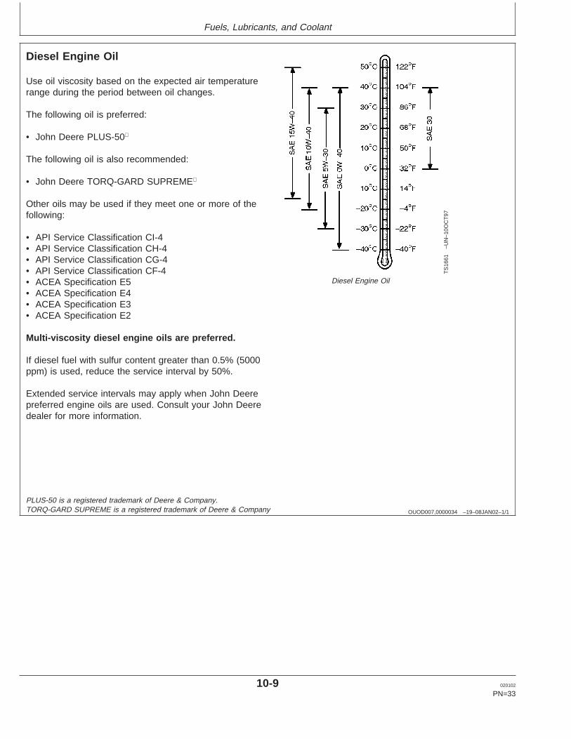
Diesel Engine Oil
TS
1661
–UN
–10O
CT
97
Diesel Engine Oil
Use oil viscosity based on the expected air temperaturerange during the period between oil changes.
The following oil is preferred:
• John Deere PLUS-50
The following oil is also recommended:
• John Deere TORQ-GARD SUPREME
Other oils may be used if they meet one or more of thefollowing:
• API Service Classification CI-4• API Service Classification CH-4• API Service Classification CG-4• API Service Classification CF-4• ACEA Specification E5• ACEA Specification E4• ACEA Specification E3• ACEA Specification E2
Multi-viscosity diesel engine oils are preferred.
If diesel fuel with sulfur content greater than 0.5% (5000ppm) is used, reduce the service interval by 50%.
Extended service intervals may apply when John Deerepreferred engine oils are used. Consult your John Deeredealer for more information.
PLUS-50 is a registered trademark of Deere & Company.TORQ-GARD SUPREME is a registered trademark of Deere & Company
10-9 020102
PN=33
Fuels, Lubricants, and Coolant
OUOD002,0000165 –19–10JAN02–1/1
Extended Diesel Engine Oil Service Intervals
When John Deere PLUS-50 oil and the specified JohnDeere filter are used, the service interval for engine oiland filter changes may be increased by 50% or to every375 hours.
If other than PLUS-50 oil and the specified John Deerefilter are used, change the engine oil and filter at thenormal service interval.
PLUS-50 is a trademark of Deere & CompanyPLUS-50 is a trademark of Deere & Company. In Europe, oils meetingACEA E5 standard can also be used.
DX,LUBMIX –19–18MAR96–1/1
Mixing of Lubricants
In general, avoid mixing different brands or types of oil.Oil manufacturers blend additives in their oils to meetcertain specifications and performance requirements.
Mixing different oils can interfere with the properfunctioning of these additives and degrade lubricantperformance.
Consult your John Deere engine distributor or servicingdealer to obtain specific information andrecommendations.
10-10 020102
PN=34
Fuels, Lubricants, and Coolant
OUOD002,0000173 –19–23NOV01–1/1
OILSCANand COOLSCAN
T68
28A
B–U
N–1
5JU
N89
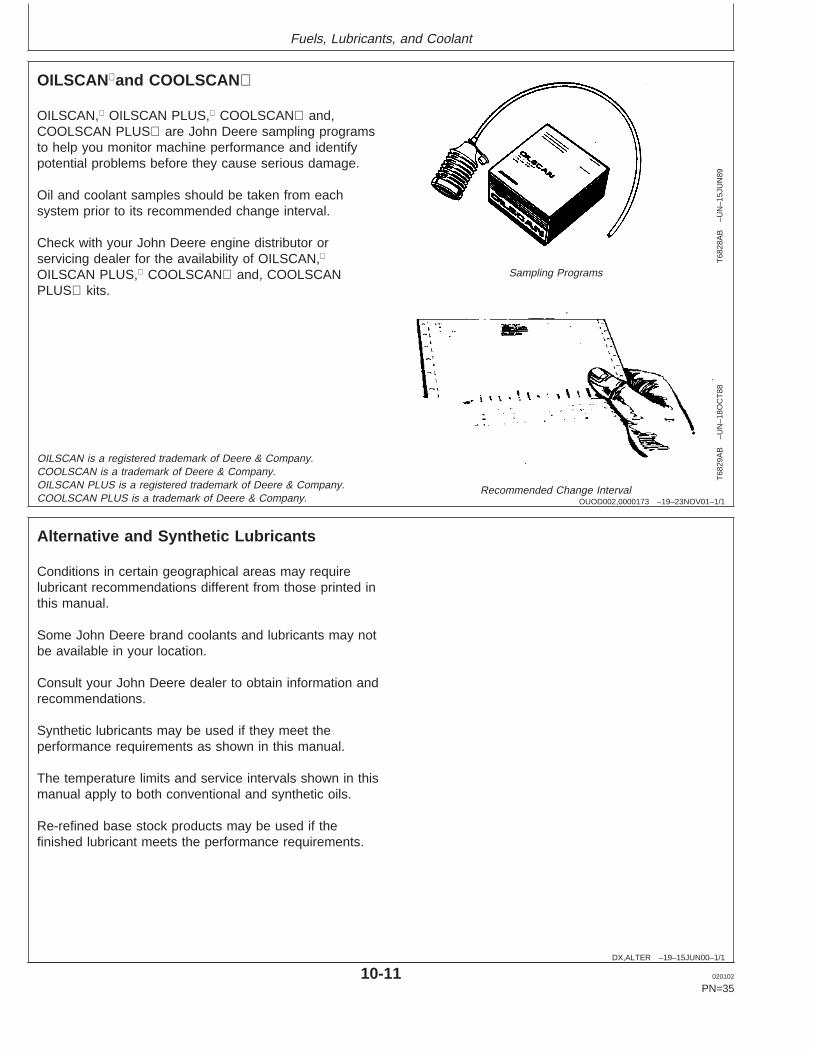
Sampling Programs
T68
29A
B–U
N–1
8OC
T88
Recommended Change Interval
OILSCAN, OILSCAN PLUS, COOLSCAN and,COOLSCAN PLUS are John Deere sampling programsto help you monitor machine performance and identifypotential problems before they cause serious damage.
Oil and coolant samples should be taken from eachsystem prior to its recommended change interval.
Check with your John Deere engine distributor orservicing dealer for the availability of OILSCAN,
OILSCAN PLUS, COOLSCAN and, COOLSCANPLUS kits.
OILSCAN is a registered trademark of Deere & Company.COOLSCAN is a trademark of Deere & Company.OILSCAN PLUS is a registered trademark of Deere & Company.COOLSCAN PLUS is a trademark of Deere & Company.
DX,ALTER –19–15JUN00–1/1
Alternative and Synthetic Lubricants
Conditions in certain geographical areas may requirelubricant recommendations different from those printed inthis manual.
Some John Deere brand coolants and lubricants may notbe available in your location.
Consult your John Deere dealer to obtain information andrecommendations.
Synthetic lubricants may be used if they meet theperformance requirements as shown in this manual.
The temperature limits and service intervals shown in thismanual apply to both conventional and synthetic oils.
Re-refined base stock products may be used if thefinished lubricant meets the performance requirements.
10-11 020102
PN=35
Fuels, Lubricants, and Coolant
DX,LUBST –19–18MAR96–1/1
Lubricant Storage
Your equipment can operate at top efficiency onlywhen clean lubricants are used.
Use clean containers to handle all lubricants.
Whenever possible, store lubricants and containers inan area protected from dust, moisture, and othercontamination. Store containers on their side to avoidwater and dirt accumulation.
Make certain that all containers are properly marked toidentify their contents.
Properly dispose of all old containers and any residuallubricant they may contain.
DX,GREA1 –19–24JAN00–1/1
Grease
TS
1667
–UN
–30J
UN
99
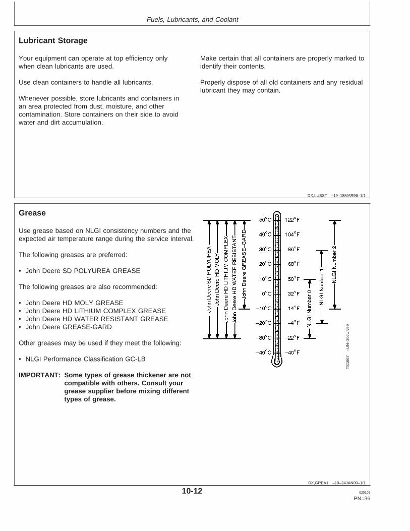
Use grease based on NLGI consistency numbers and theexpected air temperature range during the service interval.
The following greases are preferred:
• John Deere SD POLYUREA GREASE
The following greases are also recommended:
• John Deere HD MOLY GREASE• John Deere HD LITHIUM COMPLEX GREASE• John Deere HD WATER RESISTANT GREASE• John Deere GREASE-GARD
Other greases may be used if they meet the following:
• NLGI Performance Classification GC-LB
IMPORTANT: Some types of grease thickener are notcompatible with others. Consult yourgrease supplier before mixing differenttypes of grease.
10-12 020102
PN=36

Fuels, Lubricants, and Coolant
DX,COOL3 –19–05FEB99–1/1
Diesel Engine Coolant
The engine cooling system is filled to provideyear-round protection against corrosion and cylinderliner pitting, and winter freeze protection to -37°C(-34°F).
The following engine coolant is preferred for service:
• John Deere COOL-GARD Prediluted Coolant
The following engine coolant is also recommended:
• John Deere COOL-GARD Coolant Concentrate in a40 to 60% mixture of concentrate with quality water.
Other low silicate ethylene glycol base coolants forheavy-duty engines may be used if they meet one ofthe following specifications:
• ASTM D5345 (prediluted coolant)• ASTM D4985 (coolant concentrate) in a 40 to 60%
mixture of concentrate with quality water
Coolants meeting these specifications require use ofsupplemental coolant additives, formulated forheavy-duty diesel engines, for protection againstcorrosion and cylinder liner erosion and pitting.
A 50% mixture of ethylene glycol engine coolant inwater provides freeze protection to -37°C (-34°F). If
protection at lower temperatures is required, consultyour John Deere dealer for recommendations.
Water quality is important to the performance of thecooling system. Distilled, deionized, or demineralizedwater is recommended for mixing with ethylene glycolbase engine coolant concentrate.
IMPORTANT: Do not use cooling system sealingadditives or antifreeze that containssealing additives.
Coolant Drain Intervals
Drain the factory fill engine coolant, flush the coolingsystem, and refill with new coolant after the first 3years or 3000 hours of operation. Subsequent drainintervals are determined by the coolant used forservice. At each interval, drain the coolant, flush thecooling system, and refill with new coolant.
When John Deere COOL-GARD is used, the draininterval may be extended to 5 years or 5000 hours ofoperation, provided that the coolant is tested annuallyAND additives are replenished, as needed, by addinga supplemental coolant additive.
If COOL-GARD is not used, the drain interval isreduced to 2 years or 2000 hours of operation.
10-13 020102
PN=37
Fuels, Lubricants, and Coolant
DX,COOL7 –19–24JAN00–1/1
Diesel Engine Coolants, Supplemental Additive Information
Engine coolants are a combination of three chemicalcomponents: ethylene glycol (antifreeze), inhibitingcoolant additives, and quality water.
Coolant Specifications
Some products, including John Deere John DeereCOOL-GARD Prediluted Coolant, are fully formulatedcoolants that contain all three components in theircorrect concentrations. Do not add an initial charge ofsupplemental coolant additives to these fullyformulated products.
Some coolant concentrates, including John DeereCOOL-GARD Coolant Concentrate, contain bothethylene glycol antifreeze and inhibiting coolantadditives. Mix these products and quality water, but donot add an initial charge of supplemental coolantadditives.
Coolants meeting ASTM D5345 (prediluted coolant) orASTM D4985 (coolant concentrate) require an initialcharge of supplemental coolant additives.
Replenish Coolant Additives
The concentration of coolant additives is graduallydepleted during engine operation. Periodicreplenishment of inhibitors is required, even whenJohn Deere COOL-GARD is used. Follow therecommendations in this manual for the use ofsupplemental coolant additives.
Why Use Supplemental Coolant Additives?
Operating without proper coolant additives will result inincreased corrosion, cylinder liner erosion and pitting,and other damage to the engine and cooling system. Asimple mixture of ethylene glycol and water will notgive adequate protection.
Use of supplemental coolant additives reducescorrosion, erosion, and pitting. These chemicalsreduce the number of vapor bubbles in the coolant and
help form a protective film on cylinder liner surfaces.This film acts as a barrier against the harmful effectsof collapsing vapor bubbles.
Avoid Automotive-Type Coolants
Never use automotive-type coolants (such as thosemeeting ASTM D3306 or ASTM D4656). Thesecoolants do not contain the correct additives to protectheavy-duty diesel engines. They often contain a highconcentration of silicates and may damage the engineor cooling system.
Water Quality
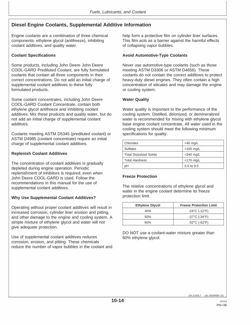
Water quality is important to the performance of thecooling system. Distilled, deionized, or demineralizedwater is recommended for mixing with ethylene glycolbase engine coolant concentrate. All water used in thecooling system should meet the following minimumspecifications for quality:
Chlorides <40 mg/L
Sulfates <100 mg/L
Total Dissolved Solids <340 mg/L
Total Hardness <170 mg/L
pH 5.5 to 9.0
Freeze Protection
The relative concentrations of ethylene glycol andwater in the engine coolant determine its freezeprotection limit.
Ethylene Glycol Freeze Protection Limit
40% -24°C (-12°F)
50% -37°C (-34°F)
60% -52°C (-62°F)
DO NOT use a coolant-water mixture greater than60% ethylene glycol.
10-14 020102
PN=38
Fuels, Lubricants, and Coolant
OUOD002,0000174 –19–18DEC01–1/1
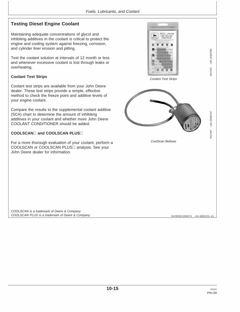
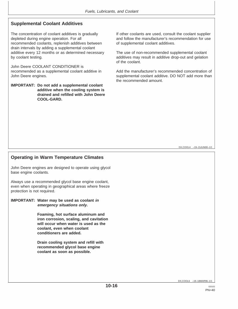
Testing Diesel Engine Coolant
RG
7297
–UN
–22S
EP
99
Coolant Test Strips
RG
7397
–UN
–05D
EC
97
CoolScan Bellows
Maintaining adequate concentrations of glycol andinhibiting additives in the coolant is critical to protect theengine and cooling system against freezing, corrosion,and cylinder liner erosion and pitting.
Test the coolant solution at intervals of 12 month or lessand whenever excessive coolant is lost through leaks oroverheating.
Coolant Test Strips
Coolant test strips are available from your John Deeredealer. These test strips provide a simple, effectivemethod to check the freeze point and additive levels ofyour engine coolant.
Compare the results to the supplemental coolant additive(SCA) chart to determine the amount of inhibitingadditives in your coolant and whether more John DeereCOOLANT CONDITIONER should be added.
COOLSCAN and COOLSCAN PLUS
For a more thorough evaluation of your coolant, perform aCOOLSCAN or COOLSCAN PLUS analysis. See yourJohn Deere dealer for information.
COOLSCAN is a trademark of Deere & CompanyCOOLSCAN PLUS is a trademark of Deere & Company.
10-15 020102
PN=39
Fuels, Lubricants, and Coolant
DX,COOL4 –19–15JUN00–1/1
Supplemental Coolant Additives
The concentration of coolant additives is graduallydepleted during engine operation. For allrecommended coolants, replenish additives betweendrain intervals by adding a supplemental coolantadditive every 12 months or as determined necessaryby coolant testing.
John Deere COOLANT CONDITIONER isrecommended as a supplemental coolant additive inJohn Deere engines.
IMPORTANT: Do not add a supplemental coolantadditive when the cooling system isdrained and refilled with John DeereCOOL-GARD.
If other coolants are used, consult the coolant supplierand follow the manufacturer’s recommendation for useof supplemental coolant additives.
The use of non-recommended supplemental coolantadditives may result in additive drop-out and gelationof the coolant.
Add the manufacturer’s recommended concentration ofsupplemental coolant additive. DO NOT add more thanthe recommended amount.
DX,COOL6 –19–18MAR96–1/1
Operating in Warm Temperature Climates
John Deere engines are designed to operate using glycolbase engine coolants.
Always use a recommended glycol base engine coolant,even when operating in geographical areas where freezeprotection is not required.
IMPORTANT: Water may be used as coolant inemergency situations only.
Foaming, hot surface aluminum andiron corrosion, scaling, and cavitationwill occur when water is used as thecoolant, even when coolantconditioners are added.
Drain cooling system and refill withrecommended glycol base enginecoolant as soon as possible.
10-16 020102
PN=40
Fuels, Lubricants, and Coolant
RG,RG34710,7543 –19–30JUN97–1/1
Disposing of Coolant
TS
1133
–UN
–26N
OV
90
Improperly disposing of engine coolant can threaten theenvironment and ecology.
Use leakproof containers when draining fluids. Do not usefood or beverage containers that may mislead someoneinto drinking from them.
Do not pour waste onto the ground, down a drain, or intoany water source.
Inquire on the proper way to recycle or dispose of wastefrom your local environmental or recycling center, or fromyour John Deere engine distributor or servicing dealer.
10-17 020102
PN=41

Engine Operating Guidelines
DPSG,RG34710,107 –19–10JAN02–1/1
Instrument (Gauge) Panels
RG
1129
9–U
N–1
2SE
P00
North American Instrument Panel
RG
1060
6A–U
N–1
9JU
N00
VDO Instrument Panel (Except North America)
All controls and gauges are optional equipment for JohnDeere OEM Engines. They may be provided by theequipment manufacturer instead of John Deere. Thefollowing information applies only to those controls andgauges provided by John Deere.
IMPORTANT: Any time an electric gauge or meterdoes not register correctly, replace itwith a new one. Do not attempt to repairit.
Two types of instrument panels are offered on 4.5 L and6.8 L engines, as shown on this page. See following forcomplete information on each type of instrument panel.
15-1 020102
PN=42
Engine Operating Guidelines
DPSG,RG34710,108 –19–08JAN02–1/2
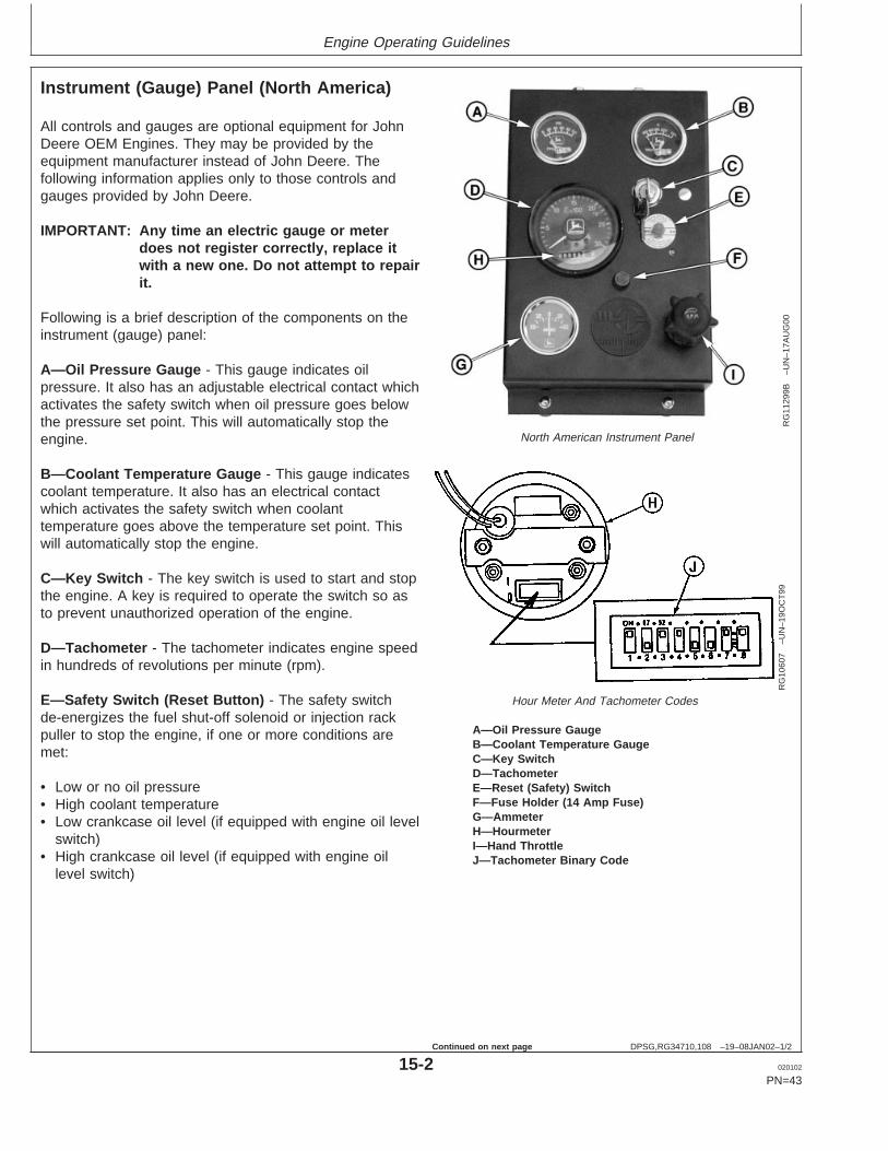
Instrument (Gauge) Panel (North America)
RG
1129
9B–U
N–1
7AU
G00
North American Instrument Panel
RG
1060
7–U
N–1
9OC
T99
Hour Meter And Tachometer Codes
A—Oil Pressure GaugeB—Coolant Temperature GaugeC—Key SwitchD—TachometerE—Reset (Safety) SwitchF—Fuse Holder (14 Amp Fuse)G—AmmeterH—HourmeterI—Hand ThrottleJ—Tachometer Binary Code
All controls and gauges are optional equipment for JohnDeere OEM Engines. They may be provided by theequipment manufacturer instead of John Deere. Thefollowing information applies only to those controls andgauges provided by John Deere.
IMPORTANT: Any time an electric gauge or meterdoes not register correctly, replace itwith a new one. Do not attempt to repairit.
Following is a brief description of the components on theinstrument (gauge) panel:
A—Oil Pressure Gauge - This gauge indicates oilpressure. It also has an adjustable electrical contact whichactivates the safety switch when oil pressure goes belowthe pressure set point. This will automatically stop theengine.
B—Coolant Temperature Gauge - This gauge indicatescoolant temperature. It also has an electrical contactwhich activates the safety switch when coolanttemperature goes above the temperature set point. Thiswill automatically stop the engine.
C—Key Switch - The key switch is used to start and stopthe engine. A key is required to operate the switch so asto prevent unauthorized operation of the engine.
D—Tachometer - The tachometer indicates engine speedin hundreds of revolutions per minute (rpm).
E—Safety Switch (Reset Button) - The safety switchde-energizes the fuel shut-off solenoid or injection rackpuller to stop the engine, if one or more conditions aremet:
• Low or no oil pressure• High coolant temperature• Low crankcase oil level (if equipped with engine oil level
switch)• High crankcase oil level (if equipped with engine oil
level switch)
15-2 020102
PN=43
Continued on next page
Engine Operating Guidelines
DPSG,RG34710,108 –19–08JAN02–2/2
The reset button has to be held in when starting theengine. The button allows the safety switch to override theshut-down circuits until safe engine oil pressure ismaintained. Once engine oil pressure is withinspecifications, the safety switch will latch and the resetbutton can be released.
F—Fuse Holder - Contains 14 amp fuse.
G—Ammeter - The ammeter indicates the rate of charge(+) or discharge (—) of the battery. When the engine isfirst started, the ammeter will usually indicate a chargerate of approximately 30 amps. After a short period ofoperation, the ammeter needle will point slightly to theright of “0”, indicating the charging system is operatingnormally. A problem with the charging system is indicatedif the ammeter needle points to the left of “0” duringengine operation.
H—Hour Meter - The hour meter operates when theengine is operating, or when the reset button is manuallyheld in while the key switch is in the ON position. Theaccumulated hours are displayed in hours and tenths ofhours. On some panels, the hourmeter may be separatefrom the tachometer.
I—Hand Throttle - The hand throttle is used to manuallycontrol engine speed. If the hand throttle is electronic (asshown), turn the knob clockwise or counterclockwise tochange engine speed. If the hand throttle is mechanical(not shown), turning the handle, either clockwise orcounterclockwise, will lock the throttle position. Turn thehandle half way between the two lock positions to unlockthe throttle.
J—Tachometer Binary Code - The tachometer iscalibrated to the number of flywheel gear teeth read. Thedip switch to set the binary code is located in back oftachometer and must be set at “10110011” to operate at30 pulses per revolution.
15-3 020102
PN=44

Engine Operating Guidelines
DPSG,RG34710,109 –19–08JAN02–1/2
VDO Instrument (Gauge) Panel (Except NorthAmerica)
RG
1060
6B–U
N–2
0OC
T99
VDO Instrument Panel
A—Oil Pressure GaugeB—Coolant Temperature GaugeC—TachometerD—Engine Control LightE—Preheater LightF—Fuel Level LightG—Battery LightH—Oil Pressure LightI—Coolant Temperature LightJ—Key/Start SwitchK—Hour Meter
All controls and gauges are optional equipment for JohnDeere OEM Engines. They may be provided by theequipment manufacturer instead of John Deere. Thefollowing information applies only to those controls andgauges provided by John Deere.
IMPORTANT: Any time an electric gauge or meterdoes not register correctly, replace itwith a new one. Do not attempt to repairit.
Following is a brief description of the components on theinstrument (gauge) panel:
A—Oil Pressure Gauge - The oil pressure gaugeindicates engine oil pressure.
B—Coolant Temperature Gauge - The coolanttemperature gauge indicates coolant temperature.
C—Tachometer - The tachometer indicates engine speedin hundreds of revolutions per minute (rpm).
The engine control system consists of the following:
D—Engine Control Light - The engine control lightilluminates after the engine has started and oil pressure isup to specification. The light indicates that the engineprotection circuitry is activated.
E—Preheater Light - The preheater light illuminateswhen the key is turned to the bulb test position (positionI). It should go off after approximately five seconds. Whenthe key switch is held in position II, the engine preheateris energized and the preheater light illuminates.
F—Fuel Level Light - The fuel level light illuminateswhen the key is turned to the bulb test position (positionI). It should go off after approximately five seconds. Afterthe engine is running, if the engine runs out of fuel, thelight will illuminate and protection circuitry will stop theengine. The fuel level light will remain on indicating theengine was stopped due to the fuel tank being empty.
15-4 020102
PN=45
Continued on next page
Engine Operating Guidelines
DPSG,RG34710,109 –19–08JAN02–2/2
G—Battery Light - The battery light illuminates when thekey is turned to the bulb test position (position I). It shouldgo off after approximately five seconds. After the engine isrunning, if the alternator stops charging, the light willilluminate and protection circuitry will stop the engine. Thebattery light will remain on indicating the engine wasstopped due to the alternator not charging.
H—Oil Pressure Light - The oil pressure light illuminateswhen the key switch is turned to the bulb test position(position I). The light will remain on until the engine isstarted and the specified oil pressure is reached. If oilpressure is lost during engine operation, the light willilluminate and protection circuitry will stop the engine. Theoil pressure light will remain on, indicating that the enginewas stopped due to a low oil pressure condition.
I—Coolant Temperature Light - The coolant temperaturelight illuminates when the key is turned to the bulb testposition (position I). It should go off after approximatelyfive seconds. After the engine is running, if the engineoverheats, the light will illuminate and protection circuitrywill stop the engine. The coolant temperature light willremain on indicating the engine was stopped due to theengine overheating.
Other components on the instrument panel:
J—Key/Start Switch - The four-position key start switchcontrols the electrical system.
K—Hour Meter - The hour meter is an integral part of thetachometer. It shows the accumulated hours of engineservice. The hour meter operates when the engine isrunning and accumulated hours are displayed in hoursand tenths of hours.
15-5 020102
PN=46
Engine Operating Guidelines
RG,RG34710,5553 –19–07JAN02–1/4
Engine Break-In Service
RG
8009
–UN
–06J
AN
99
Check Engine Oil
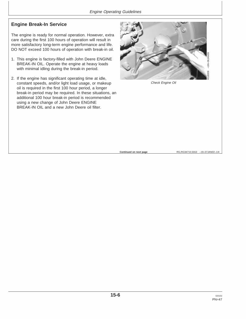
The engine is ready for normal operation. However, extracare during the first 100 hours of operation will result inmore satisfactory long-term engine performance and life.DO NOT exceed 100 hours of operation with break-in oil.
1. This engine is factory-filled with John Deere ENGINEBREAK-IN OIL. Operate the engine at heavy loadswith minimal idling during the break-in period.
2. If the engine has significant operating time at idle,constant speeds, and/or light load usage, or makeupoil is required in the first 100 hour period, a longerbreak-in period may be required. In these situations, anadditional 100 hour break-in period is recommendedusing a new change of John Deere ENGINEBREAK-IN OIL and a new John Deere oil filter.
Continued on next page
15-6 020102
PN=47
Engine Operating Guidelines
RG,RG34710,5553 –19–07JAN02–2/4
RG8028A –UN–15JAN99
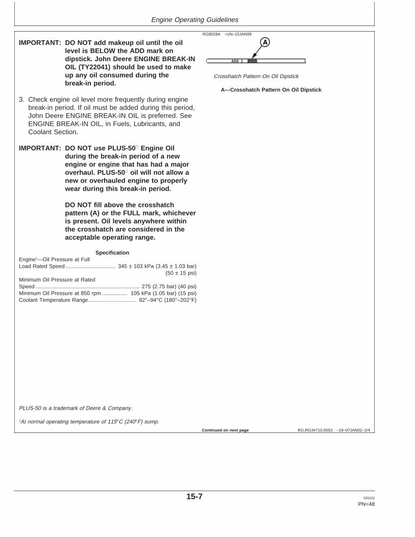
Crosshatch Pattern On Oil Dipstick
A—Crosshatch Pattern On Oil Dipstick
IMPORTANT: DO NOT add makeup oil until the oillevel is BELOW the ADD mark ondipstick. John Deere ENGINE BREAK-INOIL (TY22041) should be used to makeup any oil consumed during thebreak-in period.
3. Check engine oil level more frequently during enginebreak-in period. If oil must be added during this period,John Deere ENGINE BREAK-IN OIL is preferred. SeeENGINE BREAK-IN OIL, in Fuels, Lubricants, andCoolant Section.
IMPORTANT: DO NOT use PLUS-50 Engine Oilduring the break-in period of a newengine or engine that has had a majoroverhaul. PLUS-50 oil will not allow anew or overhauled engine to properlywear during this break-in period.
DO NOT fill above the crosshatchpattern (A) or the FULL mark, whicheveris present. Oil levels anywhere withinthe crosshatch are considered in theacceptable operating range.
SpecificationEngine1—Oil Pressure at FullLoad Rated Speed 345 ± 103 kPa (3.45 ± 1.03 bar)
(50 ± 15 psi).................................
Minimum Oil Pressure at RatedSpeed 275 (2.75 bar) (40 psi).....................................................................Minimum Oil Pressure at 850 rpm 105 kPa (1.05 bar) (15 psi).................Coolant Temperature Range 82°–94°C (180°–202°F)................................
PLUS-50 is a trademark of Deere & Company.
1At normal operating temperature of 115°C (240°F) sump.
Continued on next page
15-7 020102
PN=48
Engine Operating Guidelines
RG,RG34710,5553 –19–07JAN02–3/4
RG
7961
B–U
N–2
2JA
N99
Changing Oil And Oil Filter Before First 100 Hours
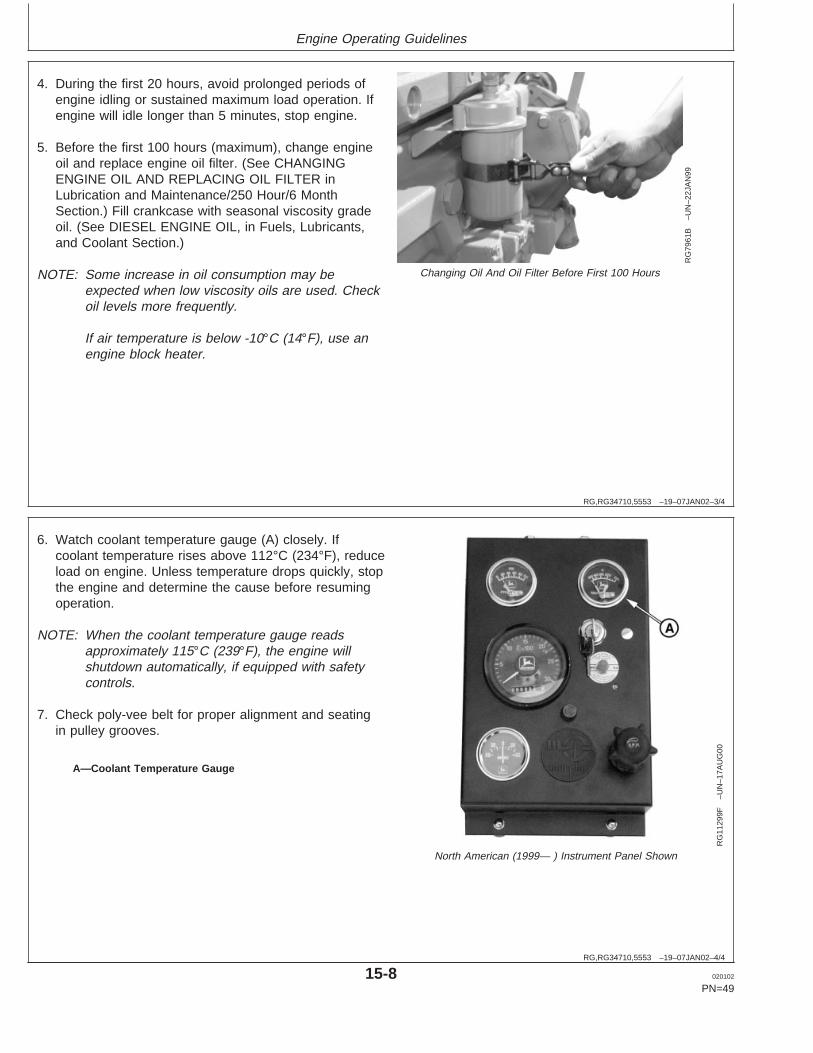
4. During the first 20 hours, avoid prolonged periods ofengine idling or sustained maximum load operation. Ifengine will idle longer than 5 minutes, stop engine.
5. Before the first 100 hours (maximum), change engineoil and replace engine oil filter. (See CHANGINGENGINE OIL AND REPLACING OIL FILTER inLubrication and Maintenance/250 Hour/6 MonthSection.) Fill crankcase with seasonal viscosity gradeoil. (See DIESEL ENGINE OIL, in Fuels, Lubricants,and Coolant Section.)
NOTE: Some increase in oil consumption may beexpected when low viscosity oils are used. Checkoil levels more frequently.
If air temperature is below -10°C (14°F), use anengine block heater.
RG,RG34710,5553 –19–07JAN02–4/4
RG
1129
9F–U
N–1
7AU
G00
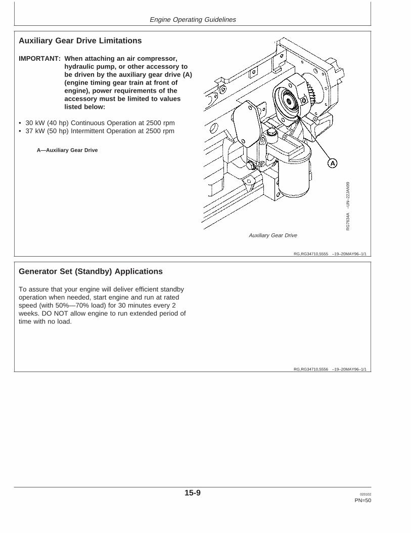
North American (1999— ) Instrument Panel Shown
A—Coolant Temperature Gauge
6. Watch coolant temperature gauge (A) closely. Ifcoolant temperature rises above 112°C (234°F), reduceload on engine. Unless temperature drops quickly, stopthe engine and determine the cause before resumingoperation.
NOTE: When the coolant temperature gauge readsapproximately 115°C (239°F), the engine willshutdown automatically, if equipped with safetycontrols.
7. Check poly-vee belt for proper alignment and seatingin pulley grooves.
15-8 020102
PN=49
Engine Operating Guidelines
RG,RG34710,5555 –19–20MAY96–1/1
Auxiliary Gear Drive Limitations
RG
7634
A–U
N–2
2JA
N99
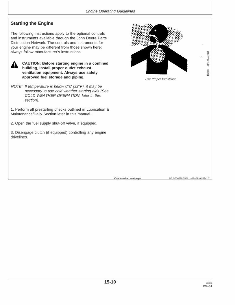
Auxiliary Gear Drive
A—Auxiliary Gear Drive
IMPORTANT: When attaching an air compressor,hydraulic pump, or other accessory tobe driven by the auxiliary gear drive (A)(engine timing gear train at front ofengine), power requirements of theaccessory must be limited to valueslisted below:
• 30 kW (40 hp) Continuous Operation at 2500 rpm• 37 kW (50 hp) Intermittent Operation at 2500 rpm
RG,RG34710,5556 –19–20MAY96–1/1
Generator Set (Standby) Applications
To assure that your engine will deliver efficient standbyoperation when needed, start engine and run at ratedspeed (with 50%—70% load) for 30 minutes every 2weeks. DO NOT allow engine to run extended period oftime with no load.
15-9 020102
PN=50
Engine Operating Guidelines
RG,RG34710,5557 –19–07JAN02–1/2
Starting the Engine
TS
220
–UN
–23A
UG
88
Use Proper Ventilation
The following instructions apply to the optional controlsand instruments available through the John Deere PartsDistribution Network. The controls and instruments foryour engine may be different from those shown here;always follow manufacturer’s instructions.
CAUTION: Before starting engine in a confinedbuilding, install proper outlet exhaustventilation equipment. Always use safetyapproved fuel storage and piping.
NOTE: If temperature is below 0°C (32°F), it may benecessary to use cold weather starting aids (SeeCOLD WEATHER OPERATION, later in thissection).
1. Perform all prestarting checks outlined in Lubrication &Maintenance/Daily Section later in this manual.
2. Open the fuel supply shut-off valve, if equipped.
3. Disengage clutch (if equipped) controlling any enginedrivelines.
Continued on next page
15-10 020102
PN=51

Engine Operating Guidelines
RG,RG34710,5557 –19–07JAN02–2/2
RG
1129
9X–U
N–1
8OC
T01
North American Standard Instrument Panel (1999— ) Shown
RG
1161
0–U
N–1
7OC
T01
VDO Standard Instrument Panel (Except North America)
A—Hand ThrottleB—Reset ButtonC—Key Start SwitchD—Oil Pressure Gauge
NOTE: Electronically controlled governor applications maybe equipped with a rotary speed potentiometer onthe throttle (A) on the instrument panel.
4. On mechanical governor (7-10% regulation) engines,pull hand throttle (A) 1/3 of the way out. Turn the handlein either direction to lock it in place.
5. If equipped, depress and hold reset button (B) whilestarting.
IMPORTANT: Do not operate the starter for more than30 seconds at a time. To do so mayoverheat the starter. If the engine doesnot start the first time, wait at least 2minutes before trying again. If enginedoes not start after four attempts, seeTroubleshooting Section.
6. Turn the key switch (C) clockwise to crank the engine.When the engine starts, release the key so that it returnsto the "ON" position.
IMPORTANT: If the key switch is released before theengine starts, wait until the starter andthe engine stop turning before tryingagain. This will prevent possibledamage to the starter and/or flywheel.
7. After the engine starts, continue to hold the reset buttonin until the oil pressure gauge (D) reads at least 105 kPa(1.05 bar) (15 psi). The safety controls will not allow theengine to run at a lower oil pressure unless the resetbutton is held in.
IMPORTANT: Should the engine die when operatingunder load, immediately disengage PTOclutch and restart the engine.Overheating of turbocharger parts mayoccur when oil flow is stopped.
8. Check all gauges for normal engine operation. Ifoperation is not normal, stop the engine and determinethe cause.
15-11 020102
PN=52
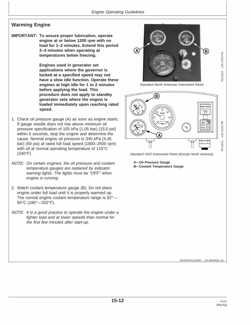
Engine Operating Guidelines
RG,RG34710,5560 –19–08JAN02–1/1
Warming Engine
RG
1161
2–U
N–1
7OC
T01
Standard North American Instrument Panel
RG
1061
3–U
N–2
1OC
T99
Standard VDO Instrument Panel (Except North America)
A—Oil Pressure GaugeB—Coolant Temperature Gauge
IMPORTANT: To assure proper lubrication, operateengine at or below 1200 rpm with noload for 1–2 minutes. Extend this period2–4 minutes when operating attemperatures below freezing.
Engines used in generator setapplications where the governor islocked at a specified speed may nothave a slow idle function. Operate theseengines at high idle for 1 to 2 minutesbefore applying the load. Thisprocedure does not apply to standbygenerator sets where the engine isloaded immediately upon reaching ratedspeed.
1. Check oil pressure gauge (A) as soon as engine starts.If gauge needle does not rise above minimum oilpressure specification of 105 kPa (1.05 bar) (15.0 psi)within 5 seconds, stop the engine and determine thecause. Normal engine oil pressure is 345 kPa (3.45bar) (50 psi) at rated full load speed (1800–2500 rpm)with oil at normal operating temperature of 115°C(240°F).
NOTE: On certain engines, the oil pressure and coolanttemperature gauges are replaced by indicatorwarning lights. The lights must be "OFF" whenengine is running.
2. Watch coolant temperature gauge (B). Do not placeengine under full load until it is properly warmed up.The normal engine coolant temperature range is 82°—94°C (180°—202°F).
NOTE: It is a good practice to operate the engine under alighter load and at lower speeds than normal forthe first few minutes after start-up.
15-12 020102
PN=53

Engine Operating Guidelines
RG,RG34710,5552 –19–20MAY96–1/1
Normal Engine Operation
Observe engine coolant temperature and engine oilpressure. Temperatures and pressures will varybetween engines and with changing operatingconditions, temperatures, and loads.
Normal engine coolant operating temperature range is82°—94°C (180°—202°F). If coolant temperature risesabove 112°C (234°F), reduce load on engine. Unlesstemperature drops quickly, stop engine and determinecause before resuming operation.
Operate the engine under a lighter load and at slowerthan normal speed for first 15 minutes after start-up.DO NOT run engine at slow idle.
IMPORTANT: Should the engine die whileoperating under load, immediately
remove load and restart the engine.Overheating of the turbochargerparts may occur when oil flow isstopped.
Stop engine immediately if there are any signs of partfailure. Symptoms that may be early signs of engineproblems are:
• Sudden drop in oil pressure• Abnormal coolant temperatures• Unusual noise or vibration• Sudden loss of power• Excessive black exhaust• Excessive fuel consumption• Excessive oil consumption• Fluid leaks
15-13 020102
PN=54

Engine Operating Guidelines
RG,RG34710,5050 –19–08JAN02–1/1
Cold Weather Operation
TS
1356
–UN
–18M
AR
92
Handle Starting Fluid with Care
RG
1152
1–1
9–10
JAN
01
Cold Weather Starting Guidelines
CAUTION: Ether injector starting fluid is highlyflammable. DO NOT use starting fluid onengines equipped with air intake heaters.
DO NOT use starting fluid near fire, sparks, orflames. DO NOT incinerate or puncture astarting fluid container.
Engines may be equipped with intake air heaters, coolantheaters, or ether injectors as a cold weather starting aid.
Starting aids are required below 32°F (0°C). They willenhance starting performance above these temperaturesand may be needed to start applications that have highparasitic loads during cranking and/or start acceleration toidle.
Using correct grade of oil (per engine and machineoperator’s manual) is critical to achieving adequate coldweather cranking speed.
Other cold weather starting aids are required attemperatures below -22°F (-30°C) or at altitudes above1500 m (5000 ft).
1. Follow steps 1—4 as listed under , then proceed asfollows according to the instrument (gauge) panel onyour engine.
2. Switch on the air intake heater for 30 seconds oractivate ether injector by following suppliersinstructions.
3. Follow remaining steps 5—8 as listed under earlier inthis section.
Additional information on cold weather operation isavailable from your authorized servicing dealer.
15-14 020102
PN=55

Engine Operating Guidelines
RG,RG34710,5561 –19–07JAN02–1/1
Changing Engine Speed
RG
1129
9I–U
N–1
1SE
P00
North American Standard Instrument Panel Shown
A—Throttle Handle
To increase engine speed, turn throttle handle (A), ifequipped, to the horizontal position and pull out untildesired engine speed is obtained. Turn the handle ineither direction to lock throttle position. The handle ispushed inward to decrease engine speed.
NOTE: On engines without handle, use throttle lever tocontrol engine speed.
RG,RG34710,5562 –19–20MAY96–1/1
Avoid Excessive Engine Idling
Prolonged idling may cause the engine coolanttemperature to fall below its normal range. This, inturn, causes crankcase oil dilution, due to incompletefuel combustion, and permits formation of gummydeposits on valves, pistons, and piston rings. It alsopromotes rapid accumulation of engine sludge andunburned fuel in the exhaust system.
Once an engine is warmed to normal operatingtemperatures, engine should be idled at slow idle
speed. Slow idle speed for this engine is 850 rpm atfactory. If an engine will be idling for more than 5minutes, stop and restart later.
NOTE: Generator set applications where the governoris locked at a specified speed may not have aslow idle function. These engines will idle at noload governed speed (high idle).
15-15 020102
PN=56

Engine Operating Guidelines
RG,RG34710,5563 –19–07JAN02–1/1
Stopping the Engine
RG
1129
9J–U
N–1
1SE
P00
North American Standard Instrument Panel Shown
RG
1061
6–U
N–1
6JU
N00
Exhaust Stack Rain Cap
A—ThrottleB—Key Switch
1. Disengage clutch (if equipped) controlling enginedrivelines.
2. Move the throttle (A) to slow idle on standard(mechanical) governor engines.
IMPORTANT: Before stopping an engine that hasbeen operating at working load, idleengine at least 2 minutes at 1000–1200rpm to cool hot engine parts.
For engines in generator setapplications, where the governor islocked at a specified speed and no slowidle function is available, run engine forat least 2 minutes at fast idle and noload.
3. Turn key switch (B) to "OFF" position to stop theengine. Remove ignition key.
IMPORTANT: Make sure that exhaust stack cap (raincap) is installed when engine is notrunning. This will prevent water and dirtfrom entering engine.
15-16 020102
PN=57

Engine Operating Guidelines
RG,RG34710,5564 –19–20MAY96–1/2
Using a Booster Battery or Charger
TS
204
–UN
–23A
UG
88
Exploding Battery
RG
4678
–UN
–14D
EC
88
12-Volt System
RG
4698
–UN
–14D
EC
88
24-Volt System
A—12-Volt Machine Battery (ies)B—12-Volt Booster Battery (ies)C—Booster CableD—Cable to Starting Motor
A 12-volt booster battery can be connected in parallel withbattery (ies) on the unit to aid in cold weather starting.ALWAYS use heavy duty jumper cables.
CAUTION: Gas given off by battery is explosive.Keep sparks and flames away from battery.Before connecting or disconnecting a batterycharger, turn charger off. Make last connectionand first disconnection at a point away frombattery. Always connect NEGATIVE (–) cablelast and disconnect this cable first.
WARNING: Battery posts, terminals, and relatedaccessories contain lead and lead compounds, chemicalsknown to the State of California to cause cancer andreproductive harm. Wash hands after handling.
IMPORTANT: Be sure polarity is correct beforemaking connections. Reversed polaritywill damage electrical system. Alwaysconnect positive to positive andnegative to ground. Always use 12-voltbooster battery for 12-volt electricalsystems and 24-volt booster battery(ies) for 24-volt electrical systems.
1. Connect booster battery or batteries to produce therequired system voltage for your engine application.
NOTE: To avoid sparks, DO NOT allow the free ends ofjumper cables to touch the engine.
2. Connect one end of jumper cable to the POSITIVE (+)post of the booster battery.
3. Connect the other end of the jumper cable to thePOSITIVE (+) post of battery connected to starter.
4. Connect one end of the other jumper cable to theNEGATIVE (–) post of the booster battery.
5. ALWAYS complete the hookup by making the lastconnection of the NEGATIVE (–) cable to a goodground on the engine frame and away from the battery(ies).
15-17 020102
PN=58
Continued on next page

Engine Operating Guidelines
RG,RG34710,5564 –19–20MAY96–2/2
6. Start the engine. Disconnect jumper cablesimmediately after engine starts. Disconnect NEGATIVE(–) cable first.
15-18 020102
PN=59
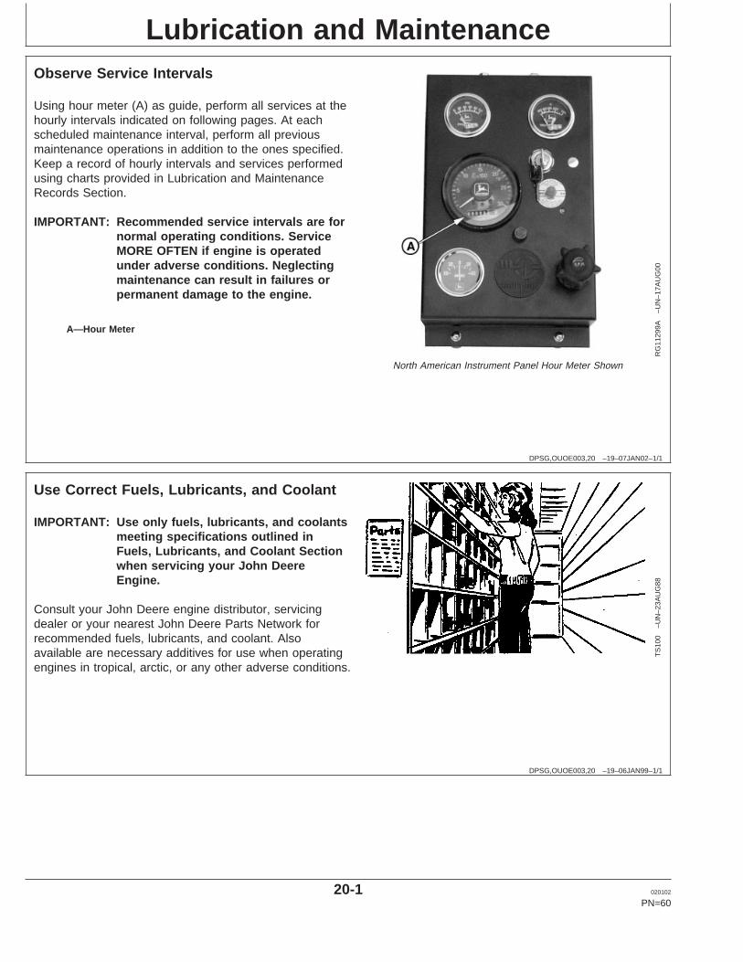
Lubrication and Maintenance
DPSG,OUOE003,20 –19–07JAN02–1/1
Observe Service Intervals
RG
1129
9A–U
N–1
7AU
G00
North American Instrument Panel Hour Meter Shown
A—Hour Meter
Using hour meter (A) as guide, perform all services at thehourly intervals indicated on following pages. At eachscheduled maintenance interval, perform all previousmaintenance operations in addition to the ones specified.Keep a record of hourly intervals and services performedusing charts provided in Lubrication and MaintenanceRecords Section.
IMPORTANT: Recommended service intervals are fornormal operating conditions. ServiceMORE OFTEN if engine is operatedunder adverse conditions. Neglectingmaintenance can result in failures orpermanent damage to the engine.
DPSG,OUOE003,20 –19–06JAN99–1/1
Use Correct Fuels, Lubricants, and Coolant
TS
100
–UN
–23A
UG
88
IMPORTANT: Use only fuels, lubricants, and coolantsmeeting specifications outlined inFuels, Lubricants, and Coolant Sectionwhen servicing your John DeereEngine.
Consult your John Deere engine distributor, servicingdealer or your nearest John Deere Parts Network forrecommended fuels, lubricants, and coolant. Alsoavailable are necessary additives for use when operatingengines in tropical, arctic, or any other adverse conditions.
20-1 020102
PN=60
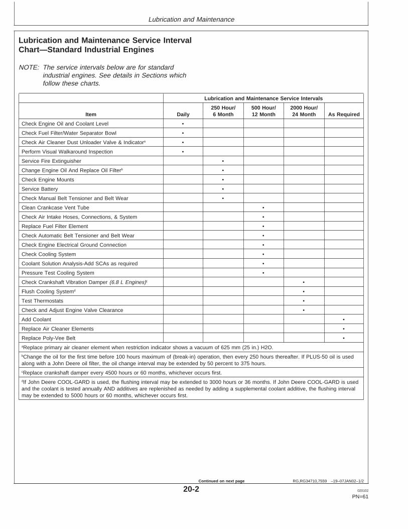
Lubrication and Maintenance
RG,RG34710,7559 –19–07JAN02–1/2
Lubrication and Maintenance Service IntervalChart—Standard Industrial Engines
NOTE: The service intervals below are for standardindustrial engines. See details in Sections whichfollow these charts.
Lubrication and Maintenance Service Intervals
250 Hour/ 500 Hour/ 2000 Hour/Item Daily 6 Month 12 Month 24 Month As Required
Check Engine Oil and Coolant Level •
Check Fuel Filter/Water Separator Bowl •
Check Air Cleaner Dust Unloader Valve & Indicatora •
Perform Visual Walkaround Inspection •
Service Fire Extinguisher •
Change Engine Oil And Replace Oil Filterb •
Check Engine Mounts •
Service Battery •
Check Manual Belt Tensioner and Belt Wear •
Clean Crankcase Vent Tube •
Check Air Intake Hoses, Connections, & System •
Replace Fuel Filter Element •
Check Automatic Belt Tensioner and Belt Wear •
Check Engine Electrical Ground Connection •
Check Cooling System •
Coolant Solution Analysis-Add SCAs as required •
Pressure Test Cooling System •
Check Crankshaft Vibration Damper (6.8 L Engines)c •
Flush Cooling Systemd •
Test Thermostats •
Check and Adjust Engine Valve Clearance •
Add Coolant •
Replace Air Cleaner Elements •
Replace Poly-Vee Belt •aReplace primary air cleaner element when restriction indicator shows a vacuum of 625 mm (25 in.) H2O.bChange the oil for the first time before 100 hours maximum of (break-in) operation, then every 250 hours thereafter. If PLUS-50 oil is usedalong with a John Deere oil filter, the oil change interval may be extended by 50 percent to 375 hours.cReplace crankshaft damper every 4500 hours or 60 months, whichever occurs first.dIf John Deere COOL-GARD is used, the flushing interval may be extended to 3000 hours or 36 months. If John Deere COOL-GARD is usedand the coolant is tested annually AND additives are replenished as needed by adding a supplemental coolant additive, the flushing intervalmay be extended to 5000 hours or 60 months, whichever occurs first.
20-2 020102
PN=61
Continued on next page
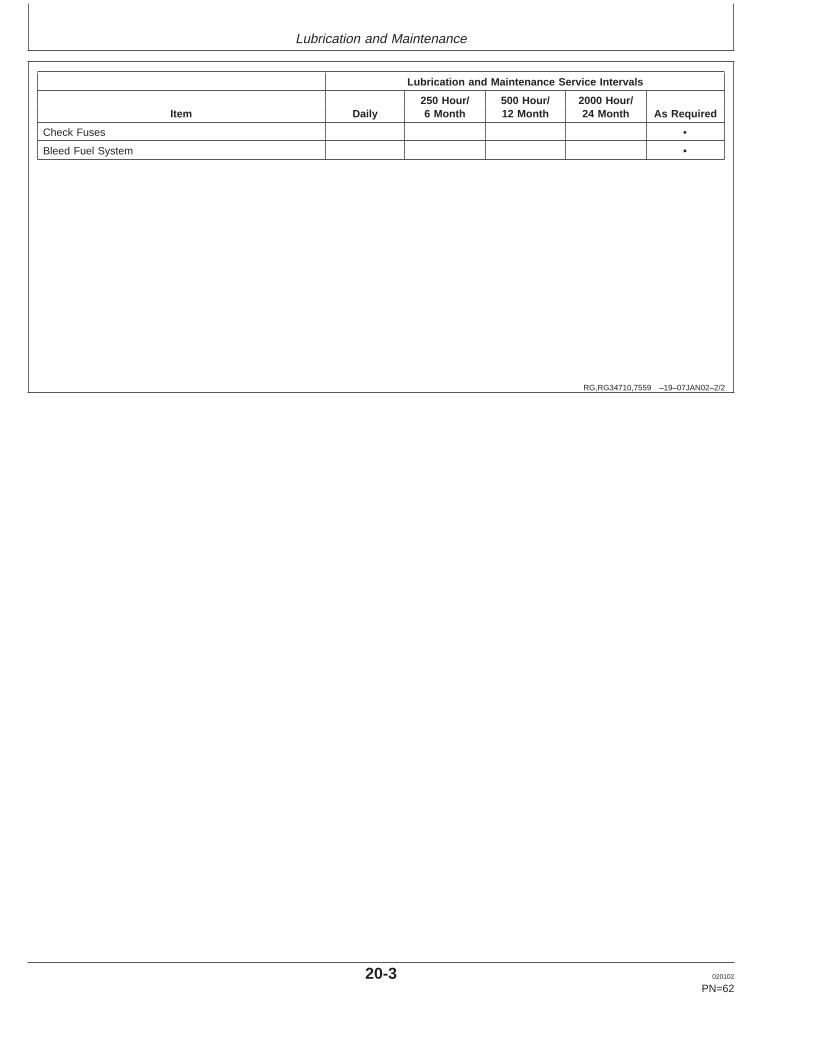
Lubrication and Maintenance
RG,RG34710,7559 –19–07JAN02–2/2
Lubrication and Maintenance Service Intervals
250 Hour/ 500 Hour/ 2000 Hour/Item Daily 6 Month 12 Month 24 Month As Required
Check Fuses •
Bleed Fuel System •
20-3 020102
PN=62

Lubrication and Maintenance
RG,RG34710,7560 –19–07JAN02–1/2
Lubrication and Maintenance Service IntervalChart—Generator (Standby) Applications
NOTE: Use service intervals listed below for generator(standby) applications. Match service items belowto titles in Lubrication and Maintenance Sectionsfor procedures.
Lubrication and Maintenance Service Intervals
Every 2 250 Hours or 500 Hours or 2000 HoursItem Weeks 12 Months 12 Months or 24 Months As Required
Operate Engine at Rated Speed and 50%–70% Load a •Minimum of 30 Minutes
Check Engine Oil and Coolant Level •
Check Fuel Filter/Water Separator Bowl •
Check Air Cleaner Dust Unloader Valve & Indicatora •
Perform Visual Walkaround Inspection •
Service Fire Extinguisher •
Change Engine Oil and Replace Oil Filterb •
Check Engine Mounts •
Service Battery •
Clean Crankcase Vent Tube •
Check Air Intake Hoses, Connections, & System •
Replace Fuel Filter Element—Bleed Fuel System •
Check Belt Tensioner and Belt Wear •
Check Engine Electrical Ground Connection •
Check Cooling System •
Coolant Solution Analysis-Add SCAs as required •
Pressure Test Cooling System •
Check Crankshaft Vibration Damper (6.8 L Engines)c •
Flush Cooling Systemd •
Test Thermostats •
Check and Adjust Engine Valve Clearance •
Add Coolant •
Replace Air Cleaner Elements •
Replace Poly-Vee Belt •aReplace primary air cleaner element when restriction indicator shows a vacuum of 625 mm (25 in.) H2O.bChange the oil for the first time before 100 hours maximum of (break-in) operation, then every 250 hours thereafter. If PLUS-50 oil is usedalong with a John Deere oil filter, the oil change interval may be extended by 50 percent to 375 hours.cReplace crankshaft damper every 4500 hours or 60 months, whichever occurs first.dIf John Deere COOL-GARD is used, the flushing interval may be extended to 3000 hours or 36 months. If John Deere COOL-GARD is usedand the coolant is tested annually AND additives are replenished as needed by adding a supplemental coolant additive, the flushing intervalmay be extended to 5000 hours or 60 months, whichever occurs first.
20-4 020102
PN=63
Continued on next page

Lubrication and Maintenance
RG,RG34710,7560 –19–07JAN02–2/2
Lubrication and Maintenance Service Intervals
Every 2 250 Hours or 500 Hours or 2000 HoursItem Weeks 12 Months 12 Months or 24 Months As Required
Check Fuses •
Bleed Fuel System •
20-5 020102
PN=64

Lubrication & Maintenance/Daily
DPSG,OUOE003,20 –19–07JAN02–1/4
Daily Prestarting Checks
RG
8009
A–U
N–1
6JU
N00
Left Side Oil Filler Cap
RG
8054
A–U
N–1
6JU
N00
Right Side Oil Filler Cap
RG
8025
B–U
N–1
6JU
N00
Rocker Arm Cover Filler CapRG8028B –UN–15JAN99
Crosshatch on Dipstick
A—Left Side Oil Filler CapB—Right Side Oil Filler CapC—Cover Oil Filler CapD—Crosshatch On Dipstick
Do the following BEFORE STARTING THE ENGINE forthe first time each day:
IMPORTANT: DO NOT add makeup oil until the oillevel is BELOW the add mark.
1. Check engine oil level on dipstick. Add as required,using seasonal viscosity grade oil. (See DIESELENGINE OIL in Fuels, Lubricants, and Coolant Sectionfor oil specifications.)
Depending on application, oil may be added at left (A)or right (B) side oil filler cap and rocker arm cover fillercap (C) locations.
IMPORTANT: DO NOT fill above the top mark on thedipstick. Oil levels anywhere withincrosshatch (D) are considered in theacceptable operating range.
Continued on next page
25-1 020102
PN=65

Lubrication & Maintenance/Daily
DPSG,OUOE003,20 –19–07JAN02–2/4T
S28
1–U
N–2
3AU
G88
High-Pressure Fluids
RG
4675
–UN
–14D
EC
88
Fill Radiator
A—Fill Radiator
CAUTION: Explosive release of fluids frompressurized cooling system can cause seriousburns.
Only remove filler cap when engine is cold orwhen cool enough to touch with bare hands.Slowly loosen cap to first stop to relievepressure before removing completely.
2. Check the coolant level when engine is cold. Coolantlevel should be at bottom of filler neck. Fill radiator (A)with proper coolant solution if level is low. (SeeADDING COOLANT in Service As Required Section.)Check overall cooling system for leaks.
NOTE: Refer to your vehicle’s operator’s manual forrecommendations for non-John Deere suppliedaccessories.
Continued on next page
25-2 020102
PN=66
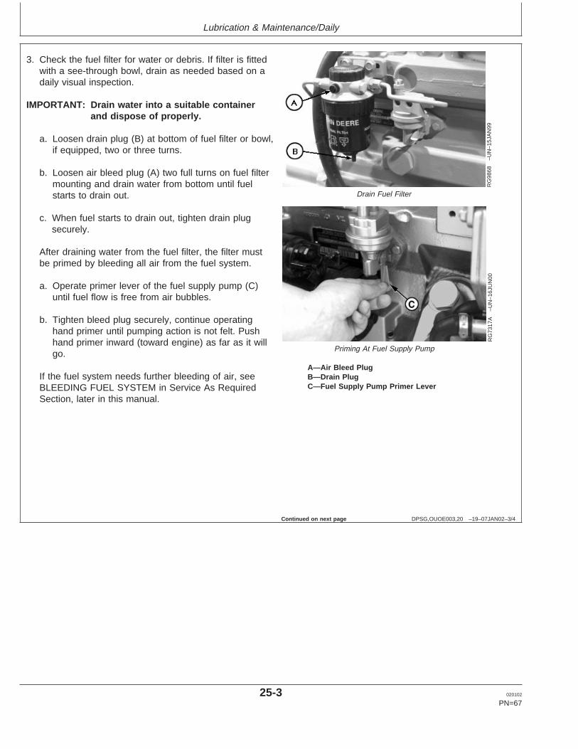
Lubrication & Maintenance/Daily
DPSG,OUOE003,20 –19–07JAN02–3/4
RG
9868
–UN
–15J
AN
99
Drain Fuel Filter
RG
7317
A–U
N–1
6JU
N00
Priming At Fuel Supply Pump
A—Air Bleed PlugB—Drain PlugC—Fuel Supply Pump Primer Lever
3. Check the fuel filter for water or debris. If filter is fittedwith a see-through bowl, drain as needed based on adaily visual inspection.
IMPORTANT: Drain water into a suitable containerand dispose of properly.
a. Loosen drain plug (B) at bottom of fuel filter or bowl,if equipped, two or three turns.
b. Loosen air bleed plug (A) two full turns on fuel filtermounting and drain water from bottom until fuelstarts to drain out.
c. When fuel starts to drain out, tighten drain plugsecurely.
After draining water from the fuel filter, the filter mustbe primed by bleeding all air from the fuel system.
a. Operate primer lever of the fuel supply pump (C)until fuel flow is free from air bubbles.
b. Tighten bleed plug securely, continue operatinghand primer until pumping action is not felt. Pushhand primer inward (toward engine) as far as it willgo.
If the fuel system needs further bleeding of air, seeBLEEDING FUEL SYSTEM in Service As RequiredSection, later in this manual.
Continued on next page
25-3 020102
PN=67
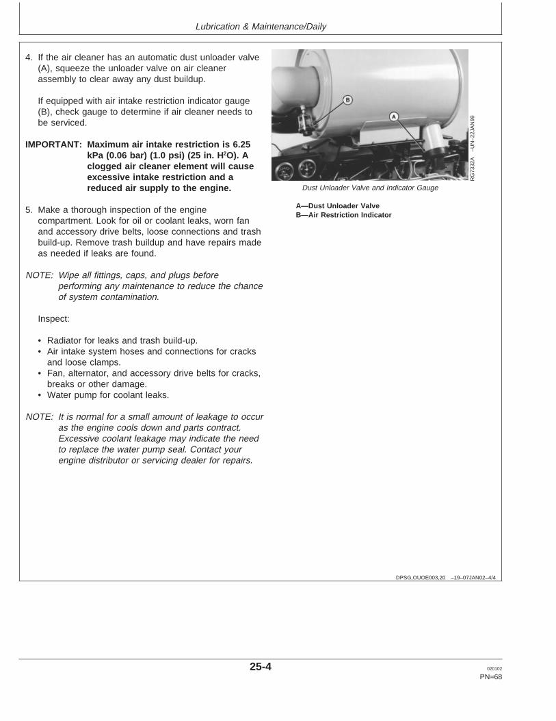
Lubrication & Maintenance/Daily
DPSG,OUOE003,20 –19–07JAN02–4/4
RG
7332
A–U
N–2
2JA
N99
Dust Unloader Valve and Indicator Gauge
A—Dust Unloader ValveB—Air Restriction Indicator
4. If the air cleaner has an automatic dust unloader valve(A), squeeze the unloader valve on air cleanerassembly to clear away any dust buildup.
If equipped with air intake restriction indicator gauge(B), check gauge to determine if air cleaner needs tobe serviced.
IMPORTANT: Maximum air intake restriction is 6.25kPa (0.06 bar) (1.0 psi) (25 in. H2O). Aclogged air cleaner element will causeexcessive intake restriction and areduced air supply to the engine.
5. Make a thorough inspection of the enginecompartment. Look for oil or coolant leaks, worn fanand accessory drive belts, loose connections and trashbuild-up. Remove trash buildup and have repairs madeas needed if leaks are found.
NOTE: Wipe all fittings, caps, and plugs beforeperforming any maintenance to reduce the chanceof system contamination.
Inspect:
• Radiator for leaks and trash build-up.• Air intake system hoses and connections for cracks
and loose clamps.• Fan, alternator, and accessory drive belts for cracks,
breaks or other damage.• Water pump for coolant leaks.
NOTE: It is normal for a small amount of leakage to occuras the engine cools down and parts contract.Excessive coolant leakage may indicate the needto replace the water pump seal. Contact yourengine distributor or servicing dealer for repairs.
25-4 020102
PN=68
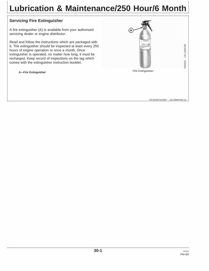
Lubrication & Maintenance/250 Hour/6 Month
RG,RG34710,5567 –19–20MAY96–1/1
Servicing Fire Extinguisher
RW
4918
–UN
–15D
EC
88
Fire ExtinguisherA—Fire Extinguisher
A fire extinguisher (A) is available from your authorizedservicing dealer or engine distributor.
Read and follow the instructions which are packaged withit. The extinguisher should be inspected at least every 250hours of engine operation or once a month. Onceextinguisher is operated, no matter how long, it must berecharged. Keep record of inspections on the tag whichcomes with the extinguisher instruction booklet.
30-1 020102
PN=69

Lubrication & Maintenance/250 Hour/6 Month
RG,RG34710,5570 –19–07JAN02–1/3
Changing Engine Oil and Replacing Filter
RG
1161
6–U
N–2
4OC
T01
Oil Filter
RG
4881
–UN
–29N
OV
88
Oil Pan Drain Plug
A—Oil Filter Element
NOTE: Change engine oil and oil filter for the first timebefore 100 hours maximum of operation, thenevery 250 hours thereafter.
If John Deere PLUS-50 engine oil and a John Deere oilfilter are used, the oil and filter change interval may beextended by 50 percent or to 375 hours.
OILSCAN or OILSCAN PLUSis a John Deere samplingprogram to help you monitor machine performance andidentify potential problems before they cause seriousdamage. OILSCAN and OILSCAN PLUSkits areavailable from your John Deere engine distributor orservicing dealer. Oil samples should be taken prior to theoil change. Refer to instructions provided with kit.
To change engine oil and oil filter:
1. Run engine approximately 5 minutes to warm up oil.Shut engine off.
2. Remove oil pan drain plug (arrow).
3. Drain crankcase oil from engine while warm.
NOTE: Drain plug location may vary, depending on theapplication.
PLUS-50 is a trademark of Deere & Company.OILSCAN is a trademark of Deere & Company.OILSCAN PLUS is a trademark of Deere & Company. Continued on next page
30-2 020102
PN=70

Lubrication & Maintenance/250 Hour/6 Month
RG,RG34710,5570 –19–07JAN02–2/3
RG
7961
A–U
N–2
2JA
N99
Removing Oil Filter Element
A—Oil Filter Element
4. Turn filter element (A) counterclockwise using asuitable filter wrench to remove. Discard oil filterelement.
NOTE: Depending on engine application, oil filter may belocated on either side of the engine.
5. Remove oil filter packing and clean filter mounting pad.
IMPORTANT: Filtration of oils is critical to properlubrication. Always change filterregularly. Use filter meeting John Deereperformance specifications.
6. Oil new packing and install new filter element. Handtighten element according to values printed on filterelement. If values are not provided, tighten elementapproximately 3/4 — 1-1/4 turn after packing contactsfilter housing. DO NOT overtighten filter element.
7. Install oil pan drain plug with O-ring or copper washer.If copper washer is used, install with raised centeragainst plug. If O-ring or washer is damaged, replaceit.
8. Tighten drain plug to specifications.
SpecificationOil Pan Drain Plug With CopperWasher—Torque 70 N•m (52 lb ft).............................................................Oil Pan Drain Plug With O-Ring—Torque 50 N•m (37 lb ft).............................................................................
Continued on next page
30-3 020102
PN=71
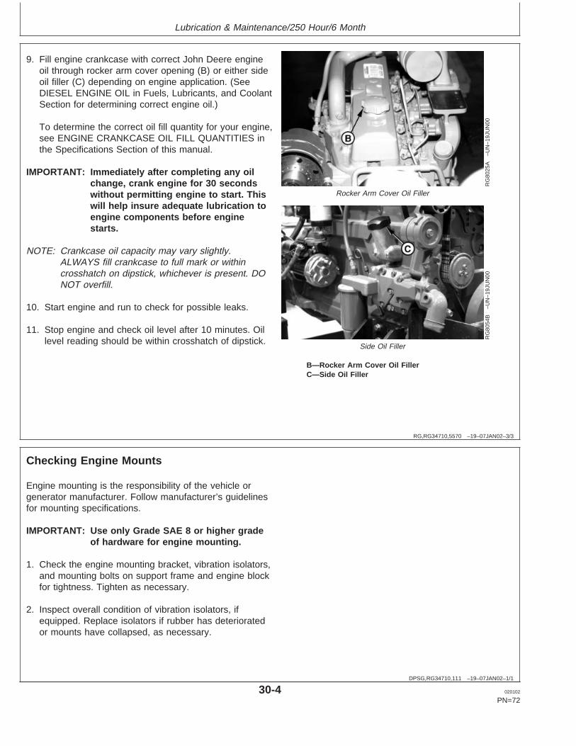
Lubrication & Maintenance/250 Hour/6 Month
RG,RG34710,5570 –19–07JAN02–3/3
RG
8025
A–U
N–1
9JU
N00
Rocker Arm Cover Oil Filler
RG
8054
B–U
N–1
9JU
N00
Side Oil Filler
B—Rocker Arm Cover Oil FillerC—Side Oil Filler
9. Fill engine crankcase with correct John Deere engineoil through rocker arm cover opening (B) or either sideoil filler (C) depending on engine application. (SeeDIESEL ENGINE OIL in Fuels, Lubricants, and CoolantSection for determining correct engine oil.)
To determine the correct oil fill quantity for your engine,see ENGINE CRANKCASE OIL FILL QUANTITIES inthe Specifications Section of this manual.
IMPORTANT: Immediately after completing any oilchange, crank engine for 30 secondswithout permitting engine to start. Thiswill help insure adequate lubrication toengine components before enginestarts.
NOTE: Crankcase oil capacity may vary slightly.ALWAYS fill crankcase to full mark or withincrosshatch on dipstick, whichever is present. DONOT overfill.
10. Start engine and run to check for possible leaks.
11. Stop engine and check oil level after 10 minutes. Oillevel reading should be within crosshatch of dipstick.
DPSG,RG34710,111 –19–07JAN02–1/1
Checking Engine Mounts
Engine mounting is the responsibility of the vehicle orgenerator manufacturer. Follow manufacturer’s guidelinesfor mounting specifications.
IMPORTANT: Use only Grade SAE 8 or higher gradeof hardware for engine mounting.
1. Check the engine mounting bracket, vibration isolators,and mounting bolts on support frame and engine blockfor tightness. Tighten as necessary.
2. Inspect overall condition of vibration isolators, ifequipped. Replace isolators if rubber has deterioratedor mounts have collapsed, as necessary.
30-4 020102
PN=72
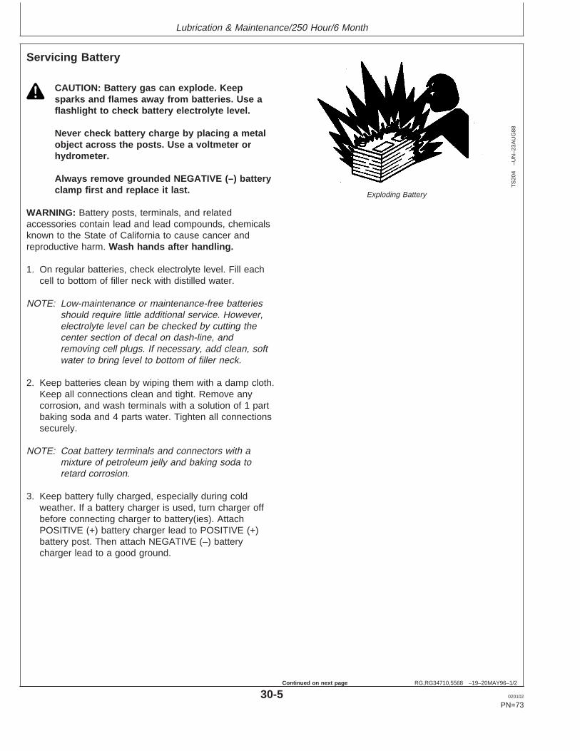
Lubrication & Maintenance/250 Hour/6 Month
RG,RG34710,5568 –19–20MAY96–1/2
Servicing Battery
TS
204
–UN
–23A
UG
88
Exploding Battery
CAUTION: Battery gas can explode. Keepsparks and flames away from batteries. Use aflashlight to check battery electrolyte level.
Never check battery charge by placing a metalobject across the posts. Use a voltmeter orhydrometer.
Always remove grounded NEGATIVE (–) batteryclamp first and replace it last.
WARNING: Battery posts, terminals, and relatedaccessories contain lead and lead compounds, chemicalsknown to the State of California to cause cancer andreproductive harm. Wash hands after handling.
1. On regular batteries, check electrolyte level. Fill eachcell to bottom of filler neck with distilled water.
NOTE: Low-maintenance or maintenance-free batteriesshould require little additional service. However,electrolyte level can be checked by cutting thecenter section of decal on dash-line, andremoving cell plugs. If necessary, add clean, softwater to bring level to bottom of filler neck.
2. Keep batteries clean by wiping them with a damp cloth.Keep all connections clean and tight. Remove anycorrosion, and wash terminals with a solution of 1 partbaking soda and 4 parts water. Tighten all connectionssecurely.
NOTE: Coat battery terminals and connectors with amixture of petroleum jelly and baking soda toretard corrosion.
3. Keep battery fully charged, especially during coldweather. If a battery charger is used, turn charger offbefore connecting charger to battery(ies). AttachPOSITIVE (+) battery charger lead to POSITIVE (+)battery post. Then attach NEGATIVE (–) batterycharger lead to a good ground.
30-5 020102
PN=73
Continued on next page

Lubrication & Maintenance/250 Hour/6 Month
RG,RG34710,5568 –19–20MAY96–2/2
TS
203
–UN
–23A
UG
88
Sulfuric Acid
CAUTION: Sulfuric acid in battery electrolyte ispoisonous. It is strong enough to burn skin, eatholes in clothing, and cause blindness ifsplashed into eyes.
Avoid the hazard by:
1. Filling batteries in a well-ventilated area.2. Wearing eye protection and rubber gloves.3. Avoiding breathing fumes when electrolyte is
added.4. Avoiding spilling or dripping electrolyte.5. Use proper jump start procedure.
If you spill acid on yourself:
1. Flush your skin with water.2. Apply baking soda or lime to help neutralize
the acid.3. Flush your eyes with water for 10–15
minutes. Get medical attention immediately.
If acid is swallowed:
1. Drink large amounts of water or milk.2. Then drink milk of magnesia, beaten eggs, or
vegetable oil.3. Get medical attention immediately.
In freezing weather, run engine at least 30 minutes toassure thorough mixing after adding water to battery.
If necessary to replace battery(ies), replacements mustmeet or exceed the following recommended capacities at-18°C (0°F):
Specification12 Volt Standard Duty Starter—Cold Cranking Amps 640............................................................................12 Volt Heavy Duty Starter—ColdCranking Amps 800.....................................................................................24 Volt Standard Duty Starter—Cold Cranking Amps 570............................................................................
30-6 020102
PN=74

Lubrication & Maintenance/250 Hour/6 Month
DPSG,RG41165,128 –19–12NOV01–1/2
Manual Belt Tensioner Adjustment
RG
1055
6–U
N–2
1DE
C99
Check Belt Tension
RG
1055
7–U
N–2
1DE
C99
Adjust Belt Tension
A—Belt Tension GaugeB—Cap ScrewC—Cap ScrewD—Tensioner Bracket
NOTE: Two types of manual tensioners shown.
NOTE: Inspect belts for cracks, fraying, or stretched-outareas. Replace if necessary.
As a reference check, twist belt in the middle of a254—305 mm (10—12 in.) span with two fingers.A properly tensioned belt will turn 75—85degrees. If belt turns more, it needs to betightened. If belt turns less, it needs to beloosened.
NOTE: If timing gear cover or alternator bracket interferewith installation/centering of belt tension gauge(A), install gauge with face toward engine.
1. Install JDG1341 Belt Tension Gauge (A) on belt,halfway between pulleys as shown. (JDG1341 BeltTension Gauge available from local John Deere Dealeror Distributor.)
2. Loosen cap screws (B) and (C).
3. Slide alternator or tensioner bracket (D) in slot by handto remove all excess slack in belt.
IMPORTANT: Do not pry against alternator rear frame.
4. Stretch belt by prying outward on alternator front frameor tensioner bracket. Observing tension gauge, stretchthe belt until specified tension is achieved.
Specification8-Rib Poly-Vee Belt—Bosch andNew Magneton Alternator NewBelt Tension 535—715 N (120—160 lb-force)...........................................Old Magneton Alternator NewBelt (Option Code 3101) Tension 470—650 N (105—145 lb-force)..........Used Belt Tension 400—580 N (90—130 lb-force)....................................
5. Tighten cap screws (B) and (C).
Continued on next page
30-7 020102
PN=75

Lubrication & Maintenance/250 Hour/6 Month
DPSG,RG41165,128 –19–12NOV01–2/2
NOTE: After ten minutes run-in, new belts are consideredused. Belt tension must then be rechecked perused belt specifications.
6. Run engine for ten minutes and immediately re-checkbelt tension per used belt specification above.
7. Reset belt tension as necessary.
OUOD002,000016D –19–05NOV01–1/2
Manual Belt Tensioner Adjustment UsingBelt Tension Tool (Alternate Method ForEngines Without Auxiliary Drive)
RG
1181
2–U
N–3
1OC
T01
Alternator Bracket and Cap Screws
RG
1181
3–U
N–3
1OC
T01
Belt Tension Tool
A—Upper Alternator Bracket Cap ScrewB—Lower Alternator Bracket Cap ScrewC—JDG1520 Belt Tension ToolD—Belt
NOTE: The JDG1520 Belt Tension Tool may not becompatible with all alternators. In that case, usethe preceeding method for belt tensioning.
NOTE: Inspect belts for cracks, fraying, or stretched-outareas. Replace if necessary.
As a reference check, twist belt in the middle of a254—305 mm (10—12 in.) span with two fingers.A properly tensioned belt will turn 75—85degrees. If belt turns more, it needs to betightened. If belt turns less, it needs to beloosened.
1. Loosen upper (A) and lower (B) alternator bracket capscrews. Lower cap screw must remain tight enough toprevent excessive alternator play but allow alternator topivot by hand.
2. Insert JDG1520 Belt Tension Tool (C) behind belt (D)and over alternator mounting screw.
Continued on next page
30-8 020102
PN=76
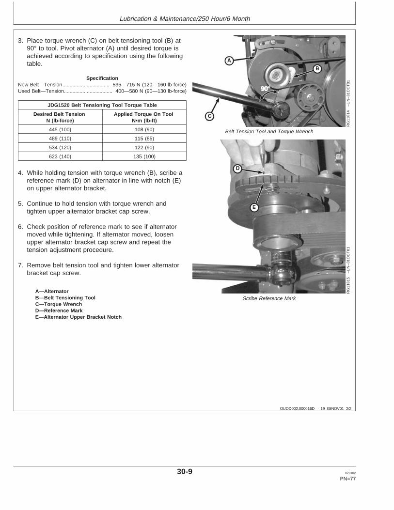
Lubrication & Maintenance/250 Hour/6 Month
OUOD002,000016D –19–05NOV01–2/2
RG
1181
4–U
N–3
1OC
T01
Belt Tension Tool and Torque Wrench
RG
1181
5–U
N–3
1OC
T01
Scribe Reference MarkA—AlternatorB—Belt Tensioning ToolC—Torque WrenchD—Reference MarkE—Alternator Upper Bracket Notch
3. Place torque wrench (C) on belt tensioning tool (B) at90° to tool. Pivot alternator (A) until desired torque isachieved according to specification using the followingtable.
SpecificationNew Belt—Tension 535—715 N (120—160 lb-force).................................Used Belt—Tension 400—580 N (90—130 lb-force)..................................
JDG1520 Belt Tensioning Tool Torque Table
Desired Belt Tension Applied Torque On ToolN (lb-force) N•m (lb-ft)
445 (100) 108 (90)
489 (110) 115 (85)
534 (120) 122 (90)
623 (140) 135 (100)
4. While holding tension with torque wrench (B), scribe areference mark (D) on alternator in line with notch (E)on upper alternator bracket.
5. Continue to hold tension with torque wrench andtighten upper alternator bracket cap screw.
6. Check position of reference mark to see if alternatormoved while tightening. If alternator moved, loosenupper alternator bracket cap screw and repeat thetension adjustment procedure.
7. Remove belt tension tool and tighten lower alternatorbracket cap screw.
30-9 020102
PN=77

Lubrication & Maintenance/500 Hour/12 Month
RG,RG34710,5574 –19–08JAN02–1/1
Cleaning Crankcase Vent Tube
RG
8017
A–U
N–1
9JU
N00
Crankcase Vent TubeA—Crankcase Vent Tube
If you operate the engine in dusty conditions, clean thetube at shorter intervals.
1. Remove and clean crankcase vent tube (A).
2. Install the vent tube. Be sure the O-ring fits correctly inthe rocker arm cover for elbow adapter. Tighten hoseclamp securely.
35-1 020102
PN=78
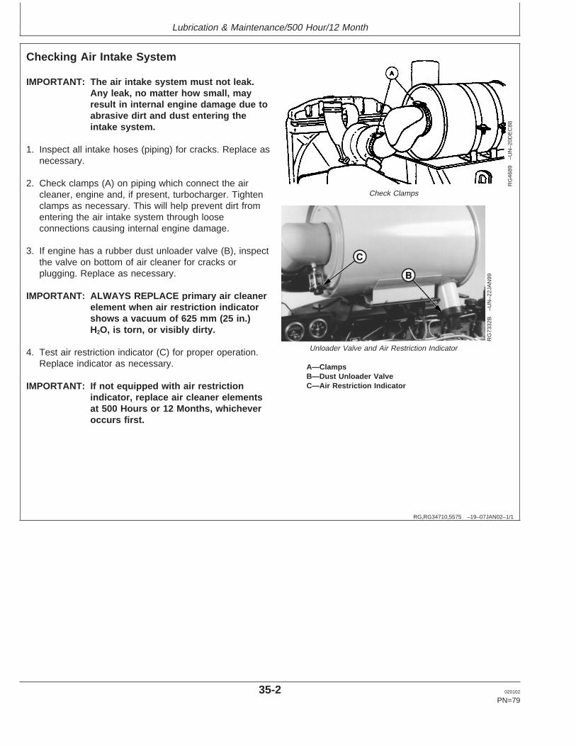
Lubrication & Maintenance/500 Hour/12 Month
RG,RG34710,5575 –19–07JAN02–1/1
Checking Air Intake System
RG
4689
–UN
–20D
EC
88
Check Clamps
RG
7332
B–U
N–2
2JA
N99
Unloader Valve and Air Restriction Indicator
A—ClampsB—Dust Unloader ValveC—Air Restriction Indicator
IMPORTANT: The air intake system must not leak.Any leak, no matter how small, mayresult in internal engine damage due toabrasive dirt and dust entering theintake system.
1. Inspect all intake hoses (piping) for cracks. Replace asnecessary.
2. Check clamps (A) on piping which connect the aircleaner, engine and, if present, turbocharger. Tightenclamps as necessary. This will help prevent dirt fromentering the air intake system through looseconnections causing internal engine damage.
3. If engine has a rubber dust unloader valve (B), inspectthe valve on bottom of air cleaner for cracks orplugging. Replace as necessary.
IMPORTANT: ALWAYS REPLACE primary air cleanerelement when air restriction indicatorshows a vacuum of 625 mm (25 in.)H2O, is torn, or visibly dirty.
4. Test air restriction indicator (C) for proper operation.Replace indicator as necessary.
IMPORTANT: If not equipped with air restrictionindicator, replace air cleaner elementsat 500 Hours or 12 Months, whicheveroccurs first.
35-2 020102
PN=79
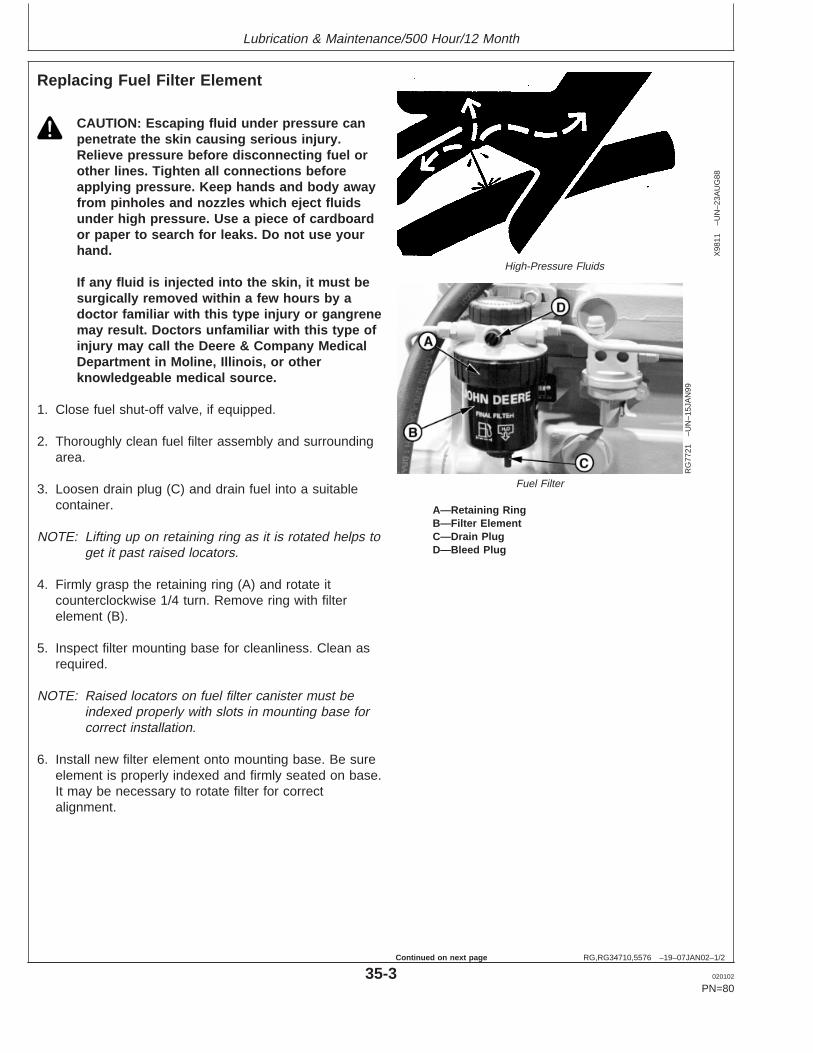
Lubrication & Maintenance/500 Hour/12 Month
RG,RG34710,5576 –19–07JAN02–1/2
Replacing Fuel Filter Element
X98
11–U
N–2
3AU
G88
High-Pressure Fluids
RG
7721
–UN
–15J
AN
99
Fuel Filter
A—Retaining RingB—Filter ElementC—Drain PlugD—Bleed Plug
CAUTION: Escaping fluid under pressure canpenetrate the skin causing serious injury.Relieve pressure before disconnecting fuel orother lines. Tighten all connections beforeapplying pressure. Keep hands and body awayfrom pinholes and nozzles which eject fluidsunder high pressure. Use a piece of cardboardor paper to search for leaks. Do not use yourhand.
If any fluid is injected into the skin, it must besurgically removed within a few hours by adoctor familiar with this type injury or gangrenemay result. Doctors unfamiliar with this type ofinjury may call the Deere & Company MedicalDepartment in Moline, Illinois, or otherknowledgeable medical source.
1. Close fuel shut-off valve, if equipped.
2. Thoroughly clean fuel filter assembly and surroundingarea.
3. Loosen drain plug (C) and drain fuel into a suitablecontainer.
NOTE: Lifting up on retaining ring as it is rotated helps toget it past raised locators.
4. Firmly grasp the retaining ring (A) and rotate itcounterclockwise 1/4 turn. Remove ring with filterelement (B).
5. Inspect filter mounting base for cleanliness. Clean asrequired.
NOTE: Raised locators on fuel filter canister must beindexed properly with slots in mounting base forcorrect installation.
6. Install new filter element onto mounting base. Be sureelement is properly indexed and firmly seated on base.It may be necessary to rotate filter for correctalignment.
35-3 020102
PN=80
Continued on next page
Lubrication & Maintenance/500 Hour/12 Month
RG,RG34710,5576 –19–07JAN02–2/2
If equipped with water separator, remove filter elementfrom water separator bowl. Drain and clean separatorbowl. Dry with compressed air. Install water separatorbowl onto new element. Tighten securely.
7. Align keys on filter element with slots in filter base.
8. Install retaining ring onto mounting base making certaindust seal is in place on filter base. Hand tighten ring(about 1/3 turn) until it “snaps” into the detent. DONOT overtighten retaining ring.
NOTE: The proper installation is indicated when a "click"is heard and a release of the retaining ring is felt.
A plug is provided with the new element forplugging the used element.
9. Open fuel shut-off valve and bleed the fuel system.(See BLEEDING FUEL SYSTEM in Service AsRequired Section.) Tighten bleed plug (D).
RG,RG34710,5578 –19–08JAN02–1/3
Checking Belt Tensioner Spring Tension andBelt Wear (Automatic Tensioner)
Belt drive systems equipped with automatic (spring) belttensioners cannot be adjusted or repaired. The automaticbelt tensioner is designed to maintain proper belt tensionover the life of the belt. If tensioner spring tension is notwithin specification, replace tensioner assembly.
Continued on next page
35-4 020102
PN=81

Lubrication & Maintenance/500 Hour/12 Month
RG,RG34710,5578 –19–08JAN02–2/3
RG
8098
–UN
–18N
OV
97
Cast Stops
A—Cast StopsB—Cast Stop
Checking Belt Wear
The belt tensioner is designed to operate within the limitof arm movement provided by the cast stops (A and B)when correct belt length and geometry is used.
Visually inspect cast stops (A and B) on belt tensionerassembly.
If the tensioner stop on swing arm (A) is hitting the fixedstop (B), check mounting brackets (alternator, belttensioner, idler pulley, etc.) and the belt length. Replacebelt as needed (see REPLACING FAN ANDALTERNATOR BELTS in Service As Required Section).
Continued on next page
35-5 020102
PN=82
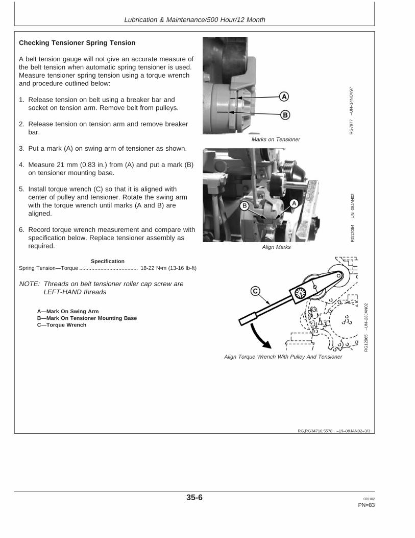
Lubrication & Maintenance/500 Hour/12 Month
RG,RG34710,5578 –19–08JAN02–3/3
RG
7977
–UN
–14N
OV
97
Marks on Tensioner
RG
1205
4–U
N–0
8JA
N02
Align Marks
RG
1206
5–U
N–2
8JA
N02
Align Torque Wrench With Pulley And Tensioner
A—Mark On Swing ArmB—Mark On Tensioner Mounting BaseC—Torque Wrench
Checking Tensioner Spring Tension
A belt tension gauge will not give an accurate measure ofthe belt tension when automatic spring tensioner is used.Measure tensioner spring tension using a torque wrenchand procedure outlined below:
1. Release tension on belt using a breaker bar andsocket on tension arm. Remove belt from pulleys.
2. Release tension on tension arm and remove breakerbar.
3. Put a mark (A) on swing arm of tensioner as shown.
4. Measure 21 mm (0.83 in.) from (A) and put a mark (B)on tensioner mounting base.
5. Install torque wrench (C) so that it is aligned withcenter of pulley and tensioner. Rotate the swing armwith the torque wrench until marks (A and B) arealigned.
6. Record torque wrench measurement and compare withspecification below. Replace tensioner assembly asrequired.
SpecificationSpring Tension—Torque 18-22 N•m (13-16 lb-ft).......................................
NOTE: Threads on belt tensioner roller cap screw areLEFT-HAND threads
35-6 020102
PN=83
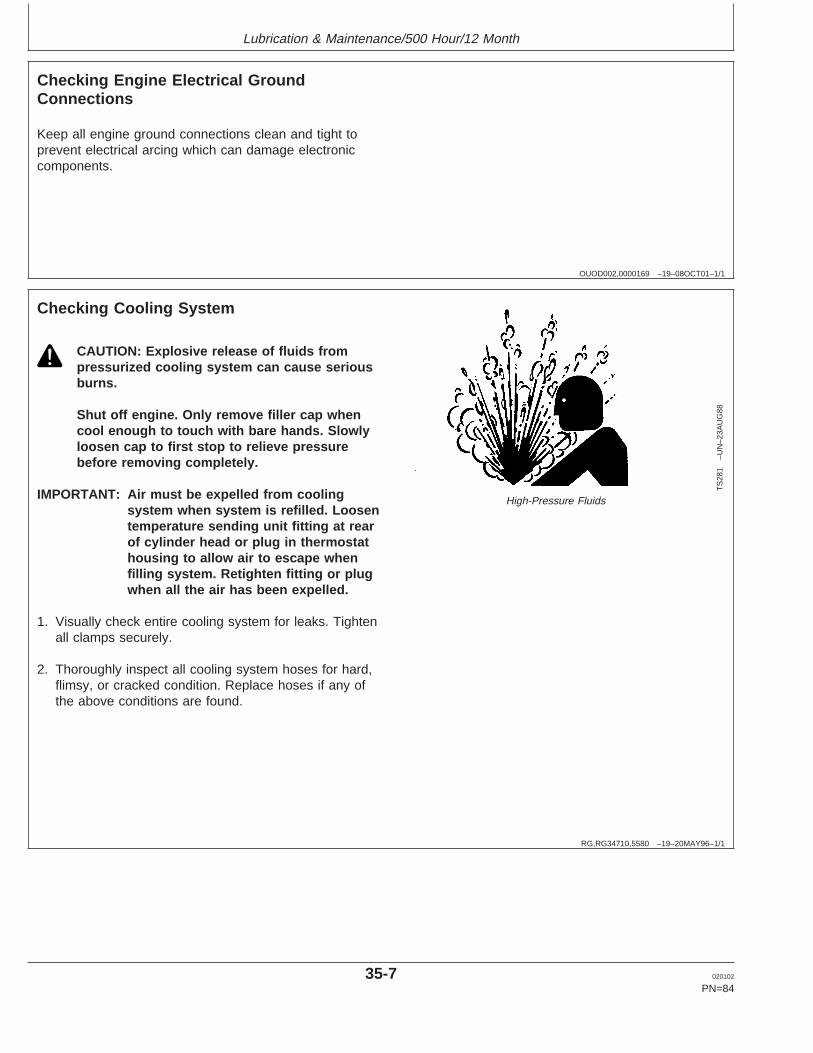
Lubrication & Maintenance/500 Hour/12 Month
OUOD002,0000169 –19–08OCT01–1/1
Checking Engine Electrical GroundConnections
Keep all engine ground connections clean and tight toprevent electrical arcing which can damage electroniccomponents.
RG,RG34710,5580 –19–20MAY96–1/1
Checking Cooling System
TS
281
–UN
–23A
UG
88
High-Pressure Fluids
CAUTION: Explosive release of fluids frompressurized cooling system can cause seriousburns.
Shut off engine. Only remove filler cap whencool enough to touch with bare hands. Slowlyloosen cap to first stop to relieve pressurebefore removing completely.
IMPORTANT: Air must be expelled from coolingsystem when system is refilled. Loosentemperature sending unit fitting at rearof cylinder head or plug in thermostathousing to allow air to escape whenfilling system. Retighten fitting or plugwhen all the air has been expelled.
1. Visually check entire cooling system for leaks. Tightenall clamps securely.
2. Thoroughly inspect all cooling system hoses for hard,flimsy, or cracked condition. Replace hoses if any ofthe above conditions are found.
35-7 020102
PN=84

Lubrication & Maintenance/500 Hour/12 Month
DPSG,OUOD002,1921 –19–07JAN02–1/2
Replenishing Supplemental CoolantAdditives (SCAs) Between Coolant Changes
RG
6261
–UN
–08D
EC
97
Radiator Coolant Check
RG
6262
–UN
–05D
EC
97
JTO7298 Coolant/Battery Tester
IMPORTANT: Do not add supplemental coolantadditives when the cooling system isdrained and refilled with John DeereCOOL-GARD
NOTE: If system is to be filled with coolant that does notcontain SCAs, the coolant must be precharged.Determine the total system capacity and premixwith 3% John Deere Coolant Conditioner.
Through time and use, the concentration of coolantadditives is gradually depleted during engine operation.Periodic replenishment of inhibitors is required, even whenJohn Deere COOL-GARD is used. The cooling systemmust be recharged with additional supplemental coolantadditives available in the form of liquid coolant conditioner.
Maintaining the correct coolant conditioner concentration(SCAs) and freeze point is essential in your coolingsystem to protect against rust, liner pitting and corrosion,and freeze-ups due to incorrect coolant dilution.
John Deere LIQUID COOLANT CONDITIONER isrecommended as a supplemental coolant additive inJohn Deere engines.
DO NOT mix one brand of SCA with a different brand.
Test the coolant solution every 500 hours or 12 months ofoperation using either John Deere coolant test strips or aCOOLSCAN analysis. If a COOLSCAN analysis is notavailable, recharge the system per instructions printed onlabel of John Deere Liquid Coolant Conditioner.
COOL-GARD is a registered trademark of Deere & CompanyCOOLSCAN is a registered trademark of Deere & Company Continued on next page
35-8 020102
PN=85

Lubrication & Maintenance/500 Hour/12 Month
DPSG,OUOD002,1921 –19–07JAN02–2/2
IMPORTANT: ALWAYS maintain coolant at correctlevel and concentration. DO NOToperate engine without coolant even fora few minutes.
If frequent coolant makeup is required,the glycol concentration should bechecked with JTO7298 Coolant/BatteryTester to ensure that the desired freezepoint is maintained. Followmanufacturer’s instructions providedwith Coolant/Battery Tester.
Add the manufacturer’s recommended concentration ofsupplemental coolant additive. DO NOT add more thanthe recommended amount.
The use of non-recommended supplemental coolantadditives may result in additive drop-out and gelation ofthe coolant.
If other coolants are used, consult the coolant supplierand follow the manufacturer’s recommendation for use ofsupplemental coolant additives.
See DIESEL ENGINE COOLANTS ANDSUPPLEMENTAL ADDITIVE INFORMATION for propermixing of coolant ingredients before adding to the coolingsystem.
35-9 020102
PN=86

Lubrication & Maintenance/500 Hour/12 Month
DX,COOL9 –19–17FEB99–1/1
Testing Diesel Engine Coolant
Maintaining adequate concentrations of glycol andinhibiting additives in the coolant is critical to protectthe engine and cooling system against freezing,corrosion, and cylinder liner erosion and pitting.
Test the coolant solution at intervals of 12 months orless and whenever excessive coolant is lost throughleaks or overheating.
Coolant Test Strips
Coolant test strips are available from your John Deeredealer. These test strips provide a simple, effectivemethod to check the freeze point and additive levels ofyour engine coolant.
Compare the results to the supplemental coolantadditive (SCA) chart to determine the amount ofinhibiting additives in your coolant and whether moreJohn Deere COOLANT CONDITIONER should beadded.
COOLSCAN
For a more thorough evaluation of your coolant,perform a COOLSCAN analysis. See your John Deeredealer for information about COOLSCAN.
35-10 020102
PN=87

Lubrication & Maintenance/500 Hour/12 Month
RG,RG34710,5586 –19–07JAN02–1/1
Pressure Testing Cooling System
RG
6557
–UN
–20J
AN
93
Test Radiator Cap
RG
6558
–UN
–20J
AN
93
Test Cooling System
CAUTION: Explosive release of fluids frompressurized cooling system can causeserious burns.
Shut off engine. Only remove filler cap whencool enough to touch with bare hands.Slowly loosen cap to first stop to relievepressure before removing completely.
Test Radiator Cap
1. Remove radiator cap and attach to D05104STTester as shown.
2. Pressurize cap to specification listed. Gauge shouldhold pressure for 10 seconds within the normalrange if cap is acceptable.
If gauge does not hold pressure, replace radiatorcap.
SpecificationRadiator Cap Holding Pressure(Not Opening For 10Seconds)—Pressure 70 kPa (0.7 bar) (10 psi)
minimum....................................
3. Remove the cap from gauge, turn it 180°, andretest cap. This will verify that the firstmeasurement was accurate.
Test Cooling System
NOTE: Engine should be warmed up to test overallcooling system.
1. Allow engine to cool, then carefully remove radiatorcap.
2. Fill radiator with coolant to the normal operatinglevel.
IMPORTANT: DO NOT apply excessive pressure tocooling system, doing so maydamage radiator and hoses.
3. Connect gauge and adapter to radiator filler neck.Pressurize cooling system to specification listed forradiator cap.
4. With pressure applied, check all cooling systemhose connections, radiator, and overall engine forleaks.
If leakage is detected, correct as necessary andpressure test system again.
If no leakage is detected, but the gauge indicated adrop in pressure, coolant may be leaking internallywithin the system or at the block-to-head gasket.Have your engine distributor or servicing dealercorrect this problem immediately.
35-11 020102
PN=88

Lubrication & Maint./2000 Hour/24 Month
RG,RG34710,5583 –19–28JAN02–1/3
Adjusting Variable Speed (Droop) onGenerator Set Engines
RG
1206
6–U
N–2
9JA
N02
Droop Adjustment Screw
A—Adjustment ScrewB—Fast Idle AdjustmentC—Slow Idle Adjustment
Stanadyne Mechanical Injection Pumps Only
1. Warm engine to normal operating temperature.
2. When necessary, disconnect throttle linkage or cable.
3. Adjust slow idle (C) and adjust fast idle (B) speedwhen necessary.
4. Run engine at fast idle, then apply load until reachingrated speed.
5. Check power. Adjust with the screw (A) if needed.
6. Remove load from engine.
7. Again check and adjust fast idle if screw (A) has beenturned.
8. Repeat procedure until both the engine power and thefast idle speed are correct.
9. Reinstall throttle linkage if previously removed.
Continued on next page
40-1 020102
PN=89

Lubrication & Maint./2000 Hour/24 Month
RG,RG34710,5583 –19–28JAN02–2/3
RG
5752
–UN
–03N
OV
97
DENSO In-Line Injection Pump
A—Fast Idle (Stop) ScrewB—Droop Adjusting Screw Access Plug LocationC—Droop Adjusting ScrewD—Slow Idle (Adjusting) ScrewE—Idle (Bumper) SpringF—Throttle LeverG—Mechanical Shutoff Lever
DENSO In-Line Injection Pumps Only
1. Check for specified no-load (frequency). If governorregulation is within 5–7% range, no adjustment isnecessary.
2. If governor regulation is above 7% or below 5%, stopengine and remove cap nuts from adjusting screwsbefore making adjustments.
3. Remove droop adjusting screw access plug (B, shownremoved) from top of governor housing.
4. Back out slow idle (adjusting) screw (D) and bumperscrew. Pull back on throttle lever (F, toward rear ofgovernor housing) by hand until the droop adjustingscrew (C) inside housing can be adjusted through theaccess plug hole.
5. Screw the droop screw in (clockwise), counting theturns until screw bottoms out. Then, return screw tooriginal setting.
NOTE: A noticeable click will occur at each 1/4 turn ofdroop adjusting screw. One click clockwise willincrease no-load speed approximately 10 rpm,counterclockwise will reduce speed by 10 rpm.
6. Screw in the droop screw (clockwise) no more than 1/2turn (two clicks) at a time to reduce governor droop.Turn counterclockwise no more than two clicks at atime to increase governor droop (to reduce governorsensitivity).
7. Replace access plug in top of governor housing. Startengine, apply full (100%) load, and readjust high idleadjusting screw until 1500 rpm is obtained at thespecified power.
8. Screw in idle (bumper) spring until engine speedincreases 5–10 rpm.
9. Repeat steps 4 through 7 until governor regulation iswithin the 5–7% range.
10. Replace all cap nuts onto adjusting screws andtighten lock nuts securely.
40-2 020102
PN=90
Continued on next page
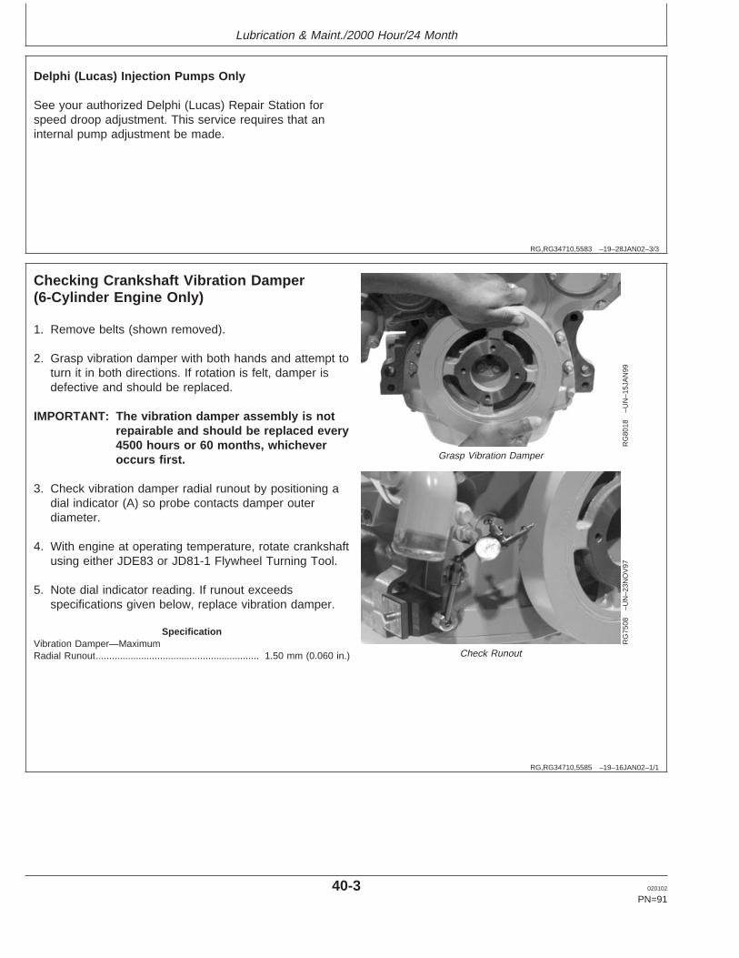
Lubrication & Maint./2000 Hour/24 Month
RG,RG34710,5583 –19–28JAN02–3/3
Delphi (Lucas) Injection Pumps Only
See your authorized Delphi (Lucas) Repair Station forspeed droop adjustment. This service requires that aninternal pump adjustment be made.
RG,RG34710,5585 –19–16JAN02–1/1
Checking Crankshaft Vibration Damper(6-Cylinder Engine Only)
RG
8018
–UN
–15J
AN
99
Grasp Vibration Damper
RG
7508
–UN
–23N
OV
97
Check Runout
1. Remove belts (shown removed).
2. Grasp vibration damper with both hands and attempt toturn it in both directions. If rotation is felt, damper isdefective and should be replaced.
IMPORTANT: The vibration damper assembly is notrepairable and should be replaced every4500 hours or 60 months, whicheveroccurs first.
3. Check vibration damper radial runout by positioning adial indicator (A) so probe contacts damper outerdiameter.
4. With engine at operating temperature, rotate crankshaftusing either JDE83 or JD81-1 Flywheel Turning Tool.
5. Note dial indicator reading. If runout exceedsspecifications given below, replace vibration damper.
SpecificationVibration Damper—MaximumRadial Runout 1.50 mm (0.060 in.).............................................................
40-3 020102
PN=91

Lubrication & Maint./2000 Hour/24 Month
RG,RG34710,5587 –19–07JAN02–1/3
Flushing Cooling System
TS
281
–UN
–23A
UG
88
High-Pressure Fluids
CAUTION: Explosive release of fluids frompressurized cooling system can cause seriousburns.
Shut off engine. Only remove filler cap whencool enough to touch with bare hands. Slowlyloosen cap to first stop to relieve pressurebefore removing completely.
NOTE: When John Deere COOL-GARD is used, the draininterval is 3000 hours or 36 months. The draininterval may be extended to 5000 hours or 60months of operation, provided that the coolantis tested annually AND additives arereplenished, as needed, by adding asupplemental coolant additive (SCA).
If COOL-GARD is not used, the flushing interval is2000 hours or 24 months of operation.
Drain old coolant, flush the entire cooling system, testthermostats, and fill with recommended clean coolant.
1. Pressure test entire cooling system and pressure cap ifnot previously done. (See PRESSURE TESTINGCOOLING SYSTEM, in the Lubrication andMaintenance/600 Hour/12 Month Section.)
2. Slowly open the engine cooling system filler cap orradiator cap to relieve pressure and allow coolant todrain faster.
Continued on next page
40-4 020102
PN=92
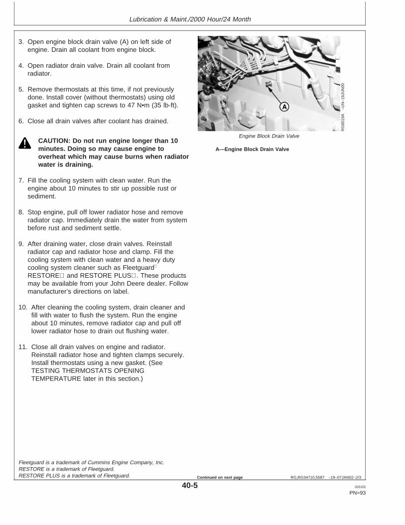
Lubrication & Maint./2000 Hour/24 Month
RG,RG34710,5587 –19–07JAN02–2/3
RG
8019
A–U
N–1
9JU
N00
Engine Block Drain Valve
A—Engine Block Drain Valve
3. Open engine block drain valve (A) on left side ofengine. Drain all coolant from engine block.
4. Open radiator drain valve. Drain all coolant fromradiator.
5. Remove thermostats at this time, if not previouslydone. Install cover (without thermostats) using oldgasket and tighten cap screws to 47 N•m (35 lb-ft).
6. Close all drain valves after coolant has drained.
CAUTION: Do not run engine longer than 10minutes. Doing so may cause engine tooverheat which may cause burns when radiatorwater is draining.
7. Fill the cooling system with clean water. Run theengine about 10 minutes to stir up possible rust orsediment.
8. Stop engine, pull off lower radiator hose and removeradiator cap. Immediately drain the water from systembefore rust and sediment settle.
9. After draining water, close drain valves. Reinstallradiator cap and radiator hose and clamp. Fill thecooling system with clean water and a heavy dutycooling system cleaner such as Fleetguard
RESTORE and RESTORE PLUS. These productsmay be available from your John Deere dealer. Followmanufacturer’s directions on label.
10. After cleaning the cooling system, drain cleaner andfill with water to flush the system. Run the engineabout 10 minutes, remove radiator cap and pull offlower radiator hose to drain out flushing water.
11. Close all drain valves on engine and radiator.Reinstall radiator hose and tighten clamps securely.Install thermostats using a new gasket. (SeeTESTING THERMOSTATS OPENINGTEMPERATURE later in this section.)
Fleetguard is a trademark of Cummins Engine Company, Inc.RESTORE is a trademark of Fleetguard.RESTORE PLUS is a trademark of Fleetguard.
40-5 020102
PN=93
Continued on next page

Lubrication & Maint./2000 Hour/24 Month
RG,RG34710,5587 –19–07JAN02–3/3
IMPORTANT: Air must be expelled from coolingsystem when system is refilled. Loosentemperature sending unit fitting at rearof cylinder head or plug in thermostathousing to allow air to escape whenfilling system. Retighten fitting or plugafter filling cooling system.
12. Add coolant to radiator until coolant touches bottom offiller neck. (See ADDING COOLANT in Service AsRequired Section.) Install radiator cap.
13. Run engine until it reaches operating temperature.This mixes the solution uniformly and circulates itthrough the entire system. The normal engine coolanttemperature range is 82°—94°C (180° — 202°F).
14. After running engine, check coolant level and entirecooling system for leaks.
40-6 020102
PN=94
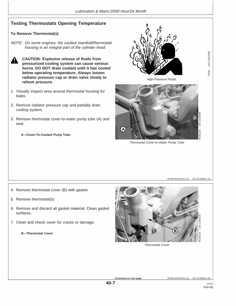
Lubrication & Maint./2000 Hour/24 Month
DPSG,RG34710,112 –19–07JAN02–1/5
Testing Thermostats Opening Temperature
TS
281
–UN
–23A
UG
88
High Pressure Fluids
RG
8115
A–U
N–1
5JA
N98
Thermostat Cover-to-Water Pump Tube
A—Cover-To-Coolant Pump Tube
To Remove Thermostat(s)
NOTE: On some engines, the coolant manifold/thermostathousing is an integral part of the cylinder head.
CAUTION: Explosive release of fluids frompressurized cooling system can cause seriousburns. DO NOT drain coolant until it has cooledbelow operating temperature. Always loosenradiator pressure cap or drain valve slowly torelieve pressure.
1. Visually inspect area around thermostat housing forleaks.
2. Remove radiator pressure cap and partially draincooling system.
3. Remove thermostat cover-to-water pump tube (A) andseal.
DPSG,RG34710,112 –19–07JAN02–2/5
RG
7921
A–U
N–1
3NO
V97
Thermostat Cover
B—Thermostat Cover
4. Remove thermostat cover (B) with gasket.
5. Remove thermostat(s)
6. Remove and discard all gasket material. Clean gasketsurfaces.
7. Clean and check cover for cracks or damage.
40-7 020102
PN=95
Continued on next page

Lubrication & Maint./2000 Hour/24 Month
DPSG,RG34710,112 –19–07JAN02–3/5
RG
5971
–UN
–23N
OV
97
Testing Thermostat Opening Temperature
Testing Thermostats Opening Temperature
1. Remove thermostat(s).
2. Visually inspect thermostat(s) for corrosion or damage.If dual thermostats, replace as a matched set asnecessary.
CAUTION: DO NOT allow thermostat orthermometer to rest against the side or bottomof container when heating water. Either mayrupture if overheated.
3. Suspend thermostat and a thermometer in a containerof water.
4. Stir the water as it heats. Observe opening action ofthermostat and compare temperatures with thespecification given in chart below.
NOTE: Due to varying tolerances of different suppliers,initial opening and full open temperatures mayvary slightly from specified temperatures.
THERMOSTAT TEST SPECIFICATIONSRating Initial Opening (Range) Full Open
(Nominal)71°C (160°F) 69—72°C (156—162°F) 84°C (182°F)77°C (170°F) 74—78°C (166—172°F) 89°C (192°F)82°C (180°F) 80—84°C (175—182°F) 94°C (202°F)89°C (192°F) 86—90°C (187—194°F) 101°C (214°F)90°C (195°F) 89—93°C (192—199°F) 103°C (218°F)92°C (197°F) 89—93°C (193—200°F) 105°C (221°F)96°C (205°F) 94—97°C (201—207°F) 100°C (213°F)99°C (210°F) 96—100°C (205—212°F) 111°C (232°F)
5. Remove thermostat and observe its closing action as itcools. In ambient air the thermostat should closecompletely. Closing action should be smooth and slow.
6. Replace any defective thermostat. On a dualthermostat engine, replace both thermostats.
Continued on next page
40-8 020102
PN=96
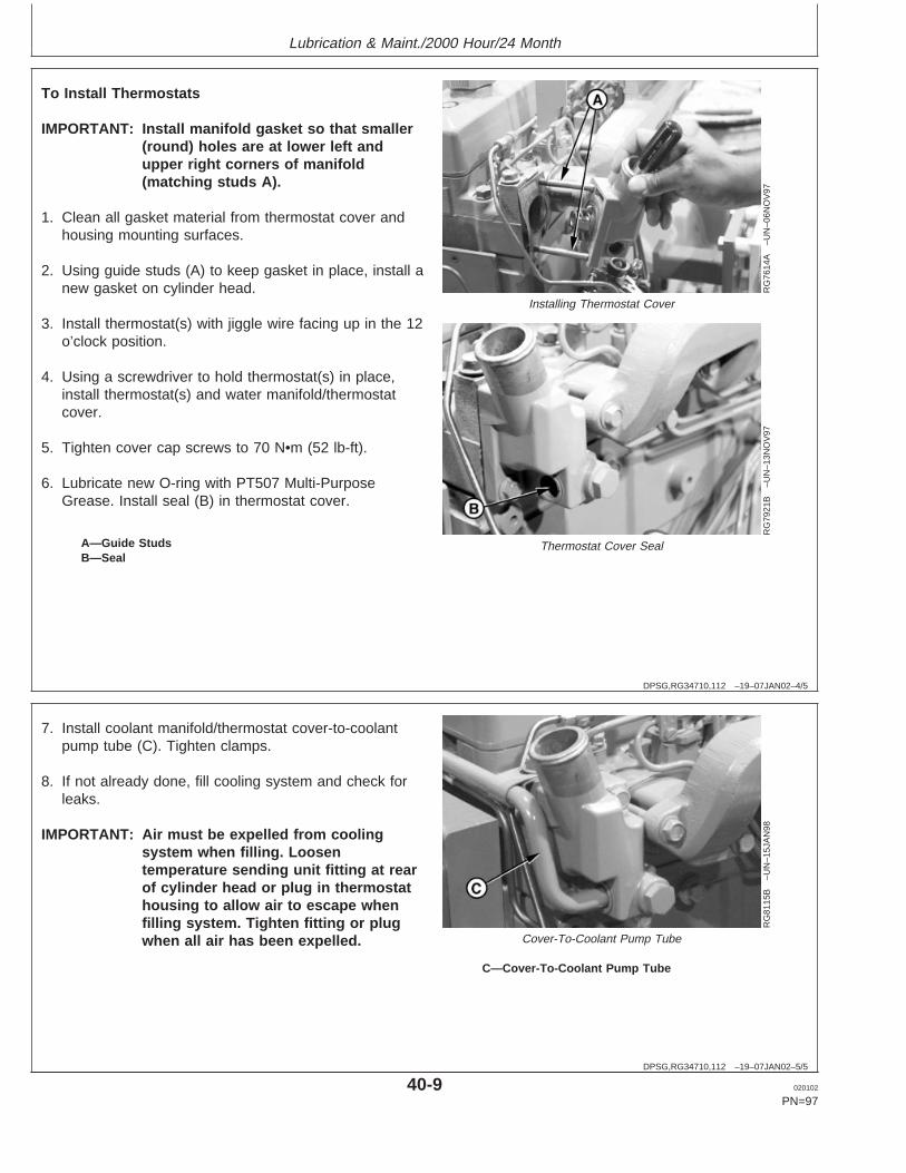
Lubrication & Maint./2000 Hour/24 Month
DPSG,RG34710,112 –19–07JAN02–4/5
RG
7614
A–U
N–0
6NO
V97
Installing Thermostat Cover
RG
7921
B–U
N–1
3NO
V97
Thermostat Cover SealA—Guide StudsB—Seal
To Install Thermostats
IMPORTANT: Install manifold gasket so that smaller(round) holes are at lower left andupper right corners of manifold(matching studs A).
1. Clean all gasket material from thermostat cover andhousing mounting surfaces.
2. Using guide studs (A) to keep gasket in place, install anew gasket on cylinder head.
3. Install thermostat(s) with jiggle wire facing up in the 12o’clock position.
4. Using a screwdriver to hold thermostat(s) in place,install thermostat(s) and water manifold/thermostatcover.
5. Tighten cover cap screws to 70 N•m (52 lb-ft).
6. Lubricate new O-ring with PT507 Multi-PurposeGrease. Install seal (B) in thermostat cover.
DPSG,RG34710,112 –19–07JAN02–5/5
RG
8115
B–U
N–1
5JA
N98
Cover-To-Coolant Pump Tube
C—Cover-To-Coolant Pump Tube
7. Install coolant manifold/thermostat cover-to-coolantpump tube (C). Tighten clamps.
8. If not already done, fill cooling system and check forleaks.
IMPORTANT: Air must be expelled from coolingsystem when filling. Loosentemperature sending unit fitting at rearof cylinder head or plug in thermostathousing to allow air to escape whenfilling system. Tighten fitting or plugwhen all air has been expelled.
40-9 020102
PN=97

Lubrication & Maint./2000 Hour/24 Month
DPSG,RG41165,137 –19–16JAN02–1/5
Check and Adjust Valve Clearance
RG
7408
–UN
–06A
UG
96
Flywheel Housing Timing Holes
A—Timing/Rotation HoleB—Timing Pin Hole
CAUTION: To prevent accidental starting ofengine while performing valve adjustments,always disconnect NEGATIVE (—) batteryterminal.
IMPORTANT: Valve clearance MUST BE checked andadjusted with engine COLD.
1. Remove rocker arm cover and crankcase ventilatortube.
IMPORTANT: Visually inspect contact surfaces ofvalve tips and rocker arm wear pads.Check all parts for excessive wear,breakage, or cracks. Replace parts thatshow visible damage.
Rocker arms that exhibit excessivevalve clearance should be inspectedmore thoroughly to identify damagedparts.
2. Remove plastic plugs or cover plate from enginetiming/rotation hole (A) and timing pin hole (B).
NOTE: Some engines are equipped with flywheelhousings which do not allow use of an engineflywheel rotation tool. These engines may berotated from front nose of engine, using JDG966Crankshaft Front/Rear Rotation Adapter.
3. Using JDE83 or JD81-1 Flywheel Turning Tool, rotateengine flywheel in running direction (clockwise viewedfrom front) until No. 1 cylinder is at TDC compressionstroke. Insert JDG1571 or JDE81-4 Timing Pin inflywheel.
If No.1 cylinder rocker arms are loose, the engine is atNo. 1 TDC compression.
If No. 1 cylinder rocker arms are not loose, rotateengine one full revolution (360°) to No. 1 TDCcompression.
40-10 020102
PN=98
Continued on next page
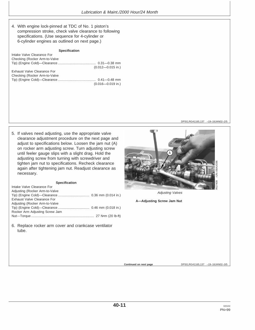
Lubrication & Maint./2000 Hour/24 Month
DPSG,RG41165,137 –19–16JAN02–2/5
4. With engine lock-pinned at TDC of No. 1 piston’scompression stroke, check valve clearance to followingspecifications. (Use sequence for 4-cylinder or6-cylinder engines as outlined on next page.)
SpecificationIntake Valve Clearance ForChecking (Rocker Arm-to-ValveTip) (Engine Cold)—Clearance 0.31—0.38 mm
(0.012—0.015 in.).........................................
Exhaust Valve Clearance ForChecking (Rocker Arm-to-ValveTip) (Engine Cold)—Clearance 0.41—0.48 mm
(0.016—0.019 in.).........................................
DPSG,RG41165,137 –19–16JAN02–3/5
RG
7409
–UN
–06A
UG
96
Adjusting Valves
A—Adjusting Screw Jam Nut
5. If valves need adjusting, use the appropriate valveclearance adjustment procedure on the next page andadjust to specifications below. Loosen the jam nut (A)on rocker arm adjusting screw. Turn adjusting screwuntil feeler gauge slips with a slight drag. Hold theadjusting screw from turning with screwdriver andtighten jam nut to specifications. Recheck clearanceagain after tightening jam nut. Readjust clearance asnecessary.
SpecificationIntake Valve Clearance ForAdjusting (Rocker Arm-to-ValveTip) (Engine Cold)—Clearance 0.36 mm (0.014 in.)..................................Exhaust Valve Clearance ForAdjusting (Rocker Arm-to-ValveTip) (Engine Cold)—Clearance 0.46 mm (0.018 in.)..................................Rocker Arm Adjusting Screw JamNut—Torque 27 N•m (20 lb-ft)....................................................................
6. Replace rocker arm cover and crankcase ventilatortube.
Continued on next page
40-11 020102
PN=99
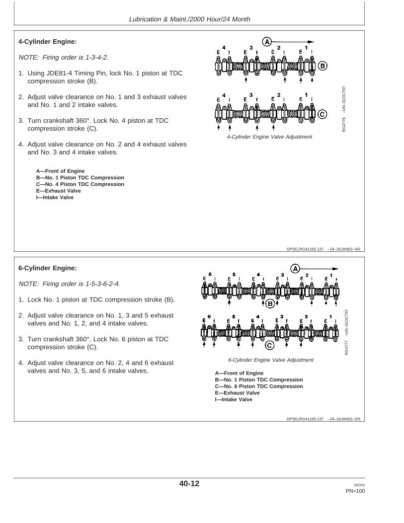
Lubrication & Maint./2000 Hour/24 Month
DPSG,RG41165,137 –19–16JAN02–4/5
RG
4776
–UN
–31O
CT
97
4-Cylinder Engine Valve Adjustment
A—Front of EngineB—No. 1 Piston TDC CompressionC—No. 4 Piston TDC CompressionE—Exhaust ValveI—Intake Valve
4-Cylinder Engine:
NOTE: Firing order is 1-3-4-2.
1. Using JDE81-4 Timing Pin, lock No. 1 piston at TDCcompression stroke (B).
2. Adjust valve clearance on No. 1 and 3 exhaust valvesand No. 1 and 2 intake valves.
3. Turn crankshaft 360°. Lock No. 4 piston at TDCcompression stroke (C).
4. Adjust valve clearance on No. 2 and 4 exhaust valvesand No. 3 and 4 intake valves.
DPSG,RG41165,137 –19–16JAN02–5/5
RG
4777
–UN
–31O
CT
97
6-Cylinder Engine Valve Adjustment
A—Front of EngineB—No. 1 Piston TDC CompressionC—No. 6 Piston TDC CompressionE—Exhaust ValveI—Intake Valve
6-Cylinder Engine:
NOTE: Firing order is 1-5-3-6-2-4.
1. Lock No. 1 piston at TDC compression stroke (B).
2. Adjust valve clearance on No. 1, 3 and 5 exhaustvalves and No. 1, 2, and 4 intake valves.
3. Turn crankshaft 360°. Lock No. 6 piston at TDCcompression stroke (C).
4. Adjust valve clearance on No. 2, 4 and 6 exhaustvalves and No. 3, 5, and 6 intake valves.
40-12 020102
PN=100

Service as Required
RG,RG34710,5591 –19–20MAY96–1/1
Additional Service Information
RG
4624
–UN
–15D
EC
88
Component Technical Manual
This is not a detailed service manual. If you want moredetailed service information, use the form in the back ofthis manual to order a component technical manual.
RG,RG34710,5592 –19–08JAN02–1/1
Do Not Modify Fuel System
RG
8022
A–U
N–1
9JU
N00
Fuel Injection Pump
IMPORTANT: Modification or alteration of theinjection pump (arrow), the injectionpump timing, or the fuel injectors inways not recommended by themanufacturer will terminate thewarranty obligation to the purchaser.
In addition, tampering with fuel systemwhich alters emission-relatedequipment on engines may result infines or other penalties, per EPAregulations or other local emissionlaws.
Do not attempt to service injectionpump or fuel injectors yourself. Specialtraining and special tools are required.(See your authorized servicing dealer orengine distributor.)
45-1 020102
PN=101
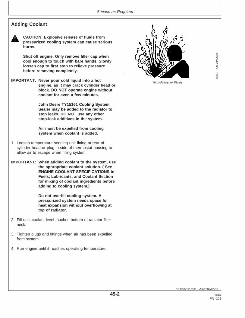
Service as Required
RG,RG34710,5593 –19–07JAN02–1/1
Adding Coolant
TS
281
–UN
–23A
UG
88
High-Pressure Fluids
CAUTION: Explosive release of fluids frompressurized cooling system can cause seriousburns.
Shut off engine. Only remove filler cap whencool enough to touch with bare hands. Slowlyloosen cap to first stop to relieve pressurebefore removing completely.
IMPORTANT: Never pour cold liquid into a hotengine, as it may crack cylinder head orblock. DO NOT operate engine withoutcoolant for even a few minutes.
John Deere TY15161 Cooling SystemSealer may be added to the radiator tostop leaks. DO NOT use any otherstop-leak additives in the system.
Air must be expelled from coolingsystem when coolant is added.
1. Loosen temperature sending unit fitting at rear ofcylinder head or plug in side of thermostat housing toallow air to escape when filling system.
IMPORTANT: When adding coolant to the system, usethe appropriate coolant solution. ( SeeENGINE COOLANT SPECIFICATIONS inFuels, Lubricants, and Coolant Sectionfor mixing of coolant ingredients beforeadding to cooling system.)
Do not overfill cooling system. Apressurized system needs space forheat expansion without overflowing attop of radiator.
2. Fill until coolant level touches bottom of radiator fillerneck.
3. Tighten plugs and fittings when air has been expelledfrom system.
4. Run engine until it reaches operating temperature.
45-2 020102
PN=102
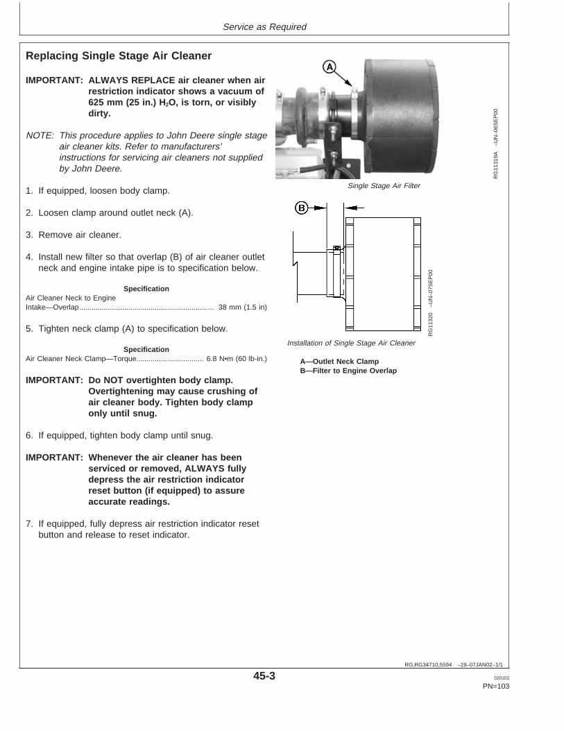
Service as Required
RG,RG34710,5594 –19–07JAN02–1/1
Replacing Single Stage Air Cleaner
RG
1131
9A–U
N–0
6SE
P00
Single Stage Air Filter
RG
1132
0–U
N–0
7SE
P00
Installation of Single Stage Air Cleaner
A—Outlet Neck ClampB—Filter to Engine Overlap
IMPORTANT: ALWAYS REPLACE air cleaner when airrestriction indicator shows a vacuum of625 mm (25 in.) H2O, is torn, or visiblydirty.
NOTE: This procedure applies to John Deere single stageair cleaner kits. Refer to manufacturers’instructions for servicing air cleaners not suppliedby John Deere.
1. If equipped, loosen body clamp.
2. Loosen clamp around outlet neck (A).
3. Remove air cleaner.
4. Install new filter so that overlap (B) of air cleaner outletneck and engine intake pipe is to specification below.
SpecificationAir Cleaner Neck to EngineIntake—Overlap 38 mm (1.5 in)..................................................................
5. Tighten neck clamp (A) to specification below.
SpecificationAir Cleaner Neck Clamp—Torque 6.8 N•m (60 lb-in.).................................
IMPORTANT: Do NOT overtighten body clamp.Overtightening may cause crushing ofair cleaner body. Tighten body clamponly until snug.
6. If equipped, tighten body clamp until snug.
IMPORTANT: Whenever the air cleaner has beenserviced or removed, ALWAYS fullydepress the air restriction indicatorreset button (if equipped) to assureaccurate readings.
7. If equipped, fully depress air restriction indicator resetbutton and release to reset indicator.
45-3 020102
PN=103
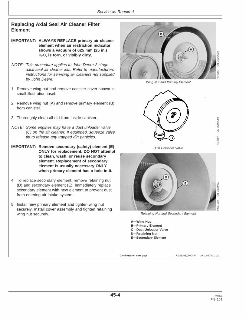
Service as Required
RG41165,000008A –19–12NOV01–1/2
Replacing Axial Seal Air Cleaner FilterElement
RG
4686
–UN
–20D
EC
88
Wing Nut and Primary Element
RG
4687
–UN
–20D
EC
88
Dust Unloader Valve
RG
1106
8–U
N–2
6JU
N00
Retaining Nut and Secondary Element
A—Wing NutB—Primary ElementC—Dust Unloader ValveD—Retaining NutE—Secondary Element
IMPORTANT: ALWAYS REPLACE primary air cleanerelement when air restriction indicatorshows a vacuum of 625 mm (25 in.)H2O, is torn, or visibly dirty.
NOTE: This procedure applies to John Deere 2-stageaxial seal air cleaner kits. Refer to manufacturers’instructions for servicing air cleaners not suppliedby John Deere.
1. Remove wing nut and remove canister cover shown insmall illustration inset.
2. Remove wing nut (A) and remove primary element (B)from canister.
3. Thoroughly clean all dirt from inside canister.
NOTE: Some engines may have a dust unloader valve(C) on the air cleaner. If equipped, squeeze valvetip to release any trapped dirt particles.
IMPORTANT: Remove secondary (safety) element (E)ONLY for replacement. DO NOT attemptto clean, wash, or reuse secondaryelement. Replacement of secondaryelement is usually necessary ONLYwhen primary element has a hole in it.
4. To replace secondary element, remove retaining nut(D) and secondary element (E). Immediately replacesecondary element with new element to prevent dustfrom entering air intake system.
5. Install new primary element and tighten wing nutsecurely. Install cover assembly and tighten retainingwing nut securely.
Continued on next page
45-4 020102
PN=104

Service as Required
RG41165,000008A –19–12NOV01–2/2
IMPORTANT: Whenever the air cleaner has beenserviced or had cover removed,ALWAYS fully depress the airrestriction indicator reset button (ifequipped) to assure accurate readings.
6. If equipped, fully depress air restriction indicator resetbutton and release to reset indicator.
45-5 020102
PN=105
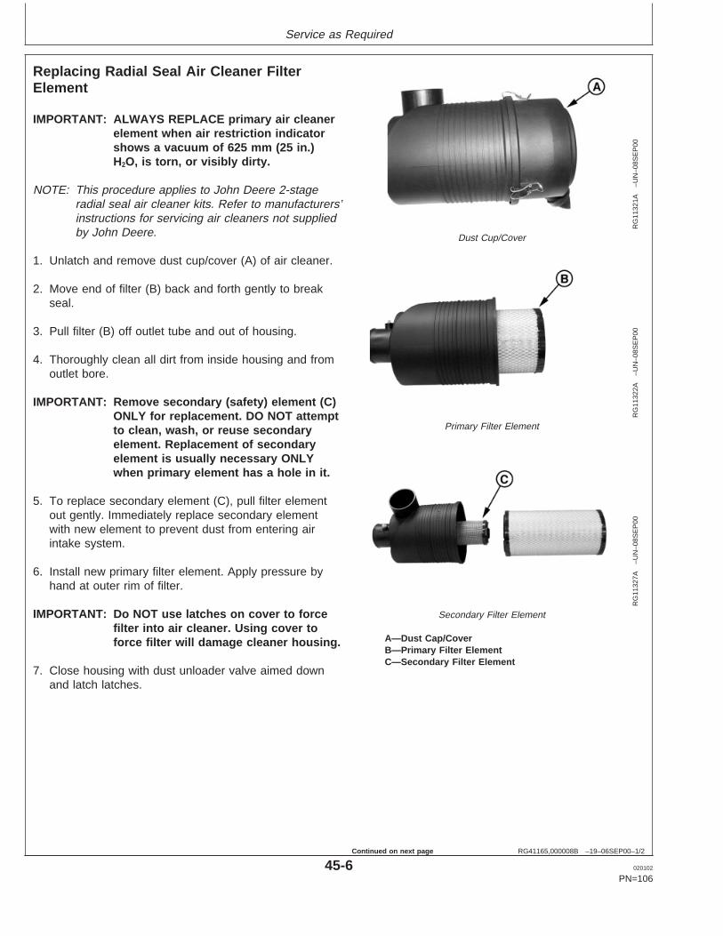
Service as Required
RG41165,000008B –19–06SEP00–1/2
Replacing Radial Seal Air Cleaner FilterElement
RG
1132
1A–U
N–0
8SE
P00
Dust Cup/Cover
RG
1132
2A–U
N–0
8SE
P00
Primary Filter Element
RG
1132
7A–U
N–0
8SE
P00
Secondary Filter Element
A—Dust Cap/CoverB—Primary Filter ElementC—Secondary Filter Element
IMPORTANT: ALWAYS REPLACE primary air cleanerelement when air restriction indicatorshows a vacuum of 625 mm (25 in.)H2O, is torn, or visibly dirty.
NOTE: This procedure applies to John Deere 2-stageradial seal air cleaner kits. Refer to manufacturers’instructions for servicing air cleaners not suppliedby John Deere.
1. Unlatch and remove dust cup/cover (A) of air cleaner.
2. Move end of filter (B) back and forth gently to breakseal.
3. Pull filter (B) off outlet tube and out of housing.
4. Thoroughly clean all dirt from inside housing and fromoutlet bore.
IMPORTANT: Remove secondary (safety) element (C)ONLY for replacement. DO NOT attemptto clean, wash, or reuse secondaryelement. Replacement of secondaryelement is usually necessary ONLYwhen primary element has a hole in it.
5. To replace secondary element (C), pull filter elementout gently. Immediately replace secondary elementwith new element to prevent dust from entering airintake system.
6. Install new primary filter element. Apply pressure byhand at outer rim of filter.
IMPORTANT: Do NOT use latches on cover to forcefilter into air cleaner. Using cover toforce filter will damage cleaner housing.
7. Close housing with dust unloader valve aimed downand latch latches.
45-6 020102
PN=106
Continued on next page

Service as Required
RG41165,000008B –19–06SEP00–2/2
IMPORTANT: Whenever the air cleaner has beenserviced or cover has been removed,ALWAYS fully depress the airrestriction indicator reset button (ifequipped) to assure accurate readings.
8. If equipped, fully depress air restriction indicator resetbutton and release to reset indicator.
45-7 020102
PN=107

Service as Required
RG,RG34710,5599 –19–12NOV01–1/1
Replacing Fan and Alternator Belts
RG
1195
0–U
N–0
7NO
V01
290 mm (11.4 in.) Fan Height and Lower*
RG
1195
1–U
N–0
7NO
V01
338 mm (13.3 in.) Fan Height and Higher Without FreonCompressor*
RG
1195
2–U
N–0
7NO
V01
402 mm (15.8 in.) Fan Height With Freon Compressor*
A—AlternatorCSP—Crankshaft PulleyFC—Freon (A/C) CompressorFD—Fan DriveI—Idler PulleyT—TensionerCP—Coolant Pump
Refer to CHECKING BELT TENSIONER SPRINGTENSION AND BELT WEAR in Lubrication andMaintenance/250 Hour/6 Month Section for additionalinformation on the belt tensioner.
1. Inspect belts for cracks, fraying, or stretched out areas.Replace if necessary.
2. To replace belt with automatic tensioner, releasetension on belt using a breaker bar and socket ontension arm.
To replace belt with manual tensioner, release tensionat belt tensioner (See MANUAL BELT TENSIONERADJUSTMENT in Lubrication and Maintenance/250Hour/6 Month Section.)
3. Remove poly-vee belt from pulleys and discard belt.
4. Install new belt, making sure belt is correctly seated inall pulley grooves. Refer to belt routing at right for yourapplication.
5. Apply tension to belt with tensioner. Remove socket.
6. Start engine and check belt alignment.
*Measured from crank centerline to fan drive center.
45-8 020102
PN=108
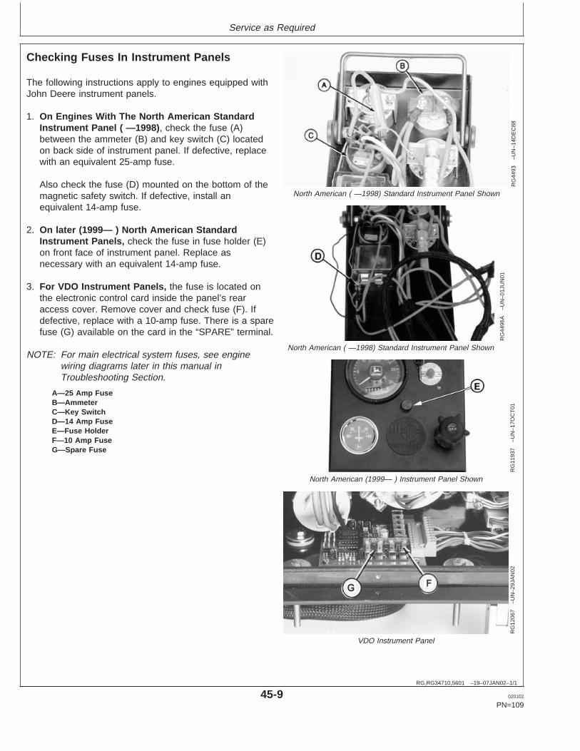
Service as Required
RG,RG34710,5601 –19–07JAN02–1/1
Checking Fuses In Instrument Panels
RG
4493
–UN
–14D
EC
88
North American ( —1998) Standard Instrument Panel Shown
RG
4496
A–U
N–0
1JU
N01
North American ( —1998) Standard Instrument Panel Shown
RG
1193
7–U
N–1
7OC
T01
North American (1999— ) Instrument Panel Shown
RG
1206
7–U
N–2
9JA
N02
VDO Instrument Panel
A—25 Amp FuseB—AmmeterC—Key SwitchD—14 Amp FuseE—Fuse HolderF—10 Amp FuseG—Spare Fuse
The following instructions apply to engines equipped withJohn Deere instrument panels.
1. On Engines With The North American StandardInstrument Panel ( —1998), check the fuse (A)between the ammeter (B) and key switch (C) locatedon back side of instrument panel. If defective, replacewith an equivalent 25-amp fuse.
Also check the fuse (D) mounted on the bottom of themagnetic safety switch. If defective, install anequivalent 14-amp fuse.
2. On later (1999— ) North American StandardInstrument Panels, check the fuse in fuse holder (E)on front face of instrument panel. Replace asnecessary with an equivalent 14-amp fuse.
3. For VDO Instrument Panels, the fuse is located onthe electronic control card inside the panel’s rearaccess cover. Remove cover and check fuse (F). Ifdefective, replace with a 10-amp fuse. There is a sparefuse (G) available on the card in the “SPARE” terminal.
NOTE: For main electrical system fuses, see enginewiring diagrams later in this manual inTroubleshooting Section.
45-9 020102
PN=109

Service as Required
RG,RG34710,5602 –19–07JAN02–1/7
Bleeding the Fuel System
X98
11–U
N–2
3AU
G88
High-Pressure Fluids
CAUTION: Escaping fluid under pressure canpenetrate the skin causing serious injury.Relieve pressure before disconnecting fuel orother lines. Tighten all connections beforeapplying pressure. Keep hands and body awayfrom pinholes and nozzles which eject fluidsunder high pressure. Use a piece of cardboardor paper to search for leaks. Do not use yourhand.
If ANY fluid is injected into the skin, it must besurgically removed within a few hours by adoctor familiar with this type injury or gangrenemay result. Doctors unfamiliar with this type ofinjury may call the Deere & Company MedicalDepartment in Moline, Illinois, or otherknowledgeable medical source.
Whenever the fuel system has been opened up forservice (lines disconnected or filters removed), it will benecessary to bleed air from the system.
RG,RG34710,5602 –19–07JAN02–2/7
RG
7947
–UN
–13N
OV
97
Air Bleed Vent Screw
A—Vent Screw
1. Loosen the air bleed vent screw (A) two full turns byhand on fuel filter base.
45-10 020102
PN=110
Continued on next page
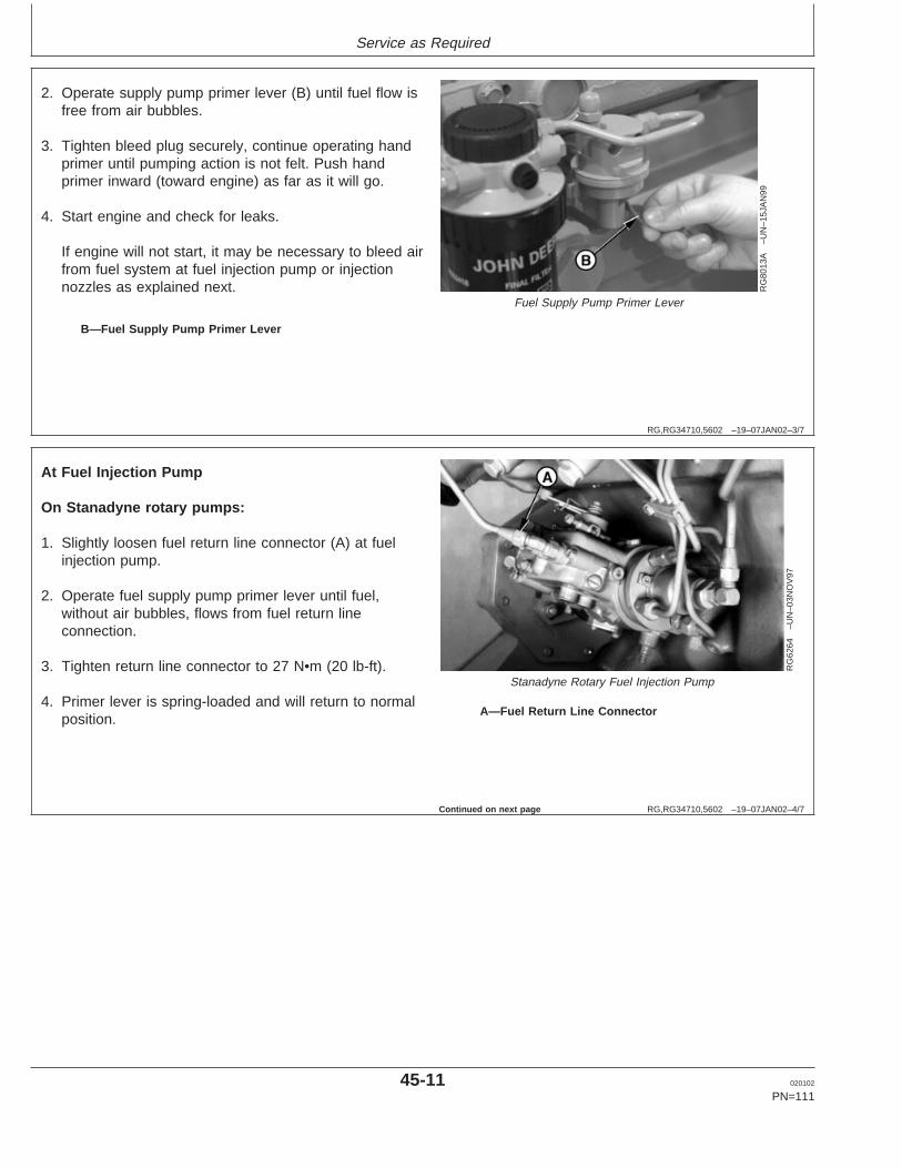
Service as Required
RG,RG34710,5602 –19–07JAN02–3/7
RG
8013
A–U
N–1
5JA
N99
Fuel Supply Pump Primer Lever
B—Fuel Supply Pump Primer Lever
2. Operate supply pump primer lever (B) until fuel flow isfree from air bubbles.
3. Tighten bleed plug securely, continue operating handprimer until pumping action is not felt. Push handprimer inward (toward engine) as far as it will go.
4. Start engine and check for leaks.
If engine will not start, it may be necessary to bleed airfrom fuel system at fuel injection pump or injectionnozzles as explained next.
RG,RG34710,5602 –19–07JAN02–4/7
RG
6264
–UN
–03N
OV
97
Stanadyne Rotary Fuel Injection Pump
A—Fuel Return Line Connector
At Fuel Injection Pump
On Stanadyne rotary pumps:
1. Slightly loosen fuel return line connector (A) at fuelinjection pump.
2. Operate fuel supply pump primer lever until fuel,without air bubbles, flows from fuel return lineconnection.
3. Tighten return line connector to 27 N•m (20 lb-ft).
4. Primer lever is spring-loaded and will return to normalposition.
Continued on next page
45-11 020102
PN=111
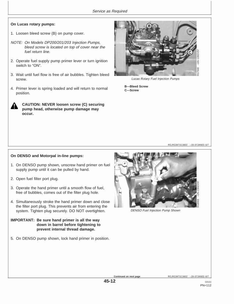
Service as Required
RG,RG34710,5602 –19–07JAN02–5/7
RG
7948
–UN
–13N
OV
97
Lucas Rotary Fuel Injection Pumps
B—Bleed ScrewC—Screw
On Lucas rotary pumps:
1. Loosen bleed screw (B) on pump cover.
NOTE: On Models DP200/201/203 Injection Pumps,bleed screw is located on top of cover near thefuel return line.
2. Operate fuel supply pump primer lever or turn ignitionswitch to “ON”.
3. Wait until fuel flow is free of air bubbles. Tighten bleedscrew.
4. Primer lever is spring loaded and will return to normalposition.
CAUTION: NEVER loosen screw (C) securingpump head, otherwise pump damage mayoccur.
RG,RG34710,5602 –19–07JAN02–6/7
RG
8069
–UN
–23N
OV
97
DENSO Fuel Injection Pump Shown
On DENSO and Motorpal in-line pumps:
1. On DENSO pump shown, unscrew hand primer on fuelsupply pump until it can be pulled by hand.
2. Open fuel filter port plug.
3. Operate the hand primer until a smooth flow of fuel,free of bubbles, comes out of the filter plug hole.
4. Simultaneously stroke the hand primer down and closethe filter port plug. This prevents air from entering thesystem. Tighten plug securely. DO NOT overtighten.
IMPORTANT: Be sure hand primer is all the waydown in barrel before tightening toprevent internal thread damage.
5. On DENSO pump shown, lock hand primer in position.
45-12 020102
PN=112
Continued on next page
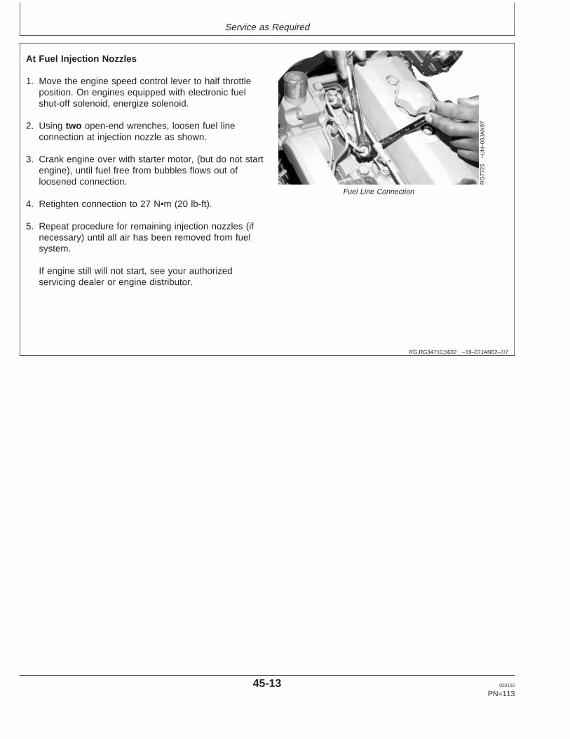
Service as Required
RG,RG34710,5602 –19–07JAN02–7/7
RG
7725
–UN
–08J
AN
97
Fuel Line Connection
At Fuel Injection Nozzles
1. Move the engine speed control lever to half throttleposition. On engines equipped with electronic fuelshut-off solenoid, energize solenoid.
2. Using two open-end wrenches, loosen fuel lineconnection at injection nozzle as shown.
3. Crank engine over with starter motor, (but do not startengine), until fuel free from bubbles flows out ofloosened connection.
4. Retighten connection to 27 N•m (20 lb-ft).
5. Repeat procedure for remaining injection nozzles (ifnecessary) until all air has been removed from fuelsystem.
If engine still will not start, see your authorizedservicing dealer or engine distributor.
45-13 020102
PN=113
Troubleshooting
RG,RG34710,5605 –19–07JAN02–1/1
General Troubleshooting Information
Troubleshooting engine problems can be difficult. Anengine wiring diagram is provided in this section tohelp isolate electrical problems on power units usingJohn Deere wiring harness and instrument (gauge)panel.
Wiring diagrams are shown for the two types ofinstrument panels offered for these engines.
Later in this section is a list of possible engineproblems that may be encountered accompanied bypossible causes and corrections. The illustrateddiagrams and troubleshooting information are of ageneral nature, final design of the overall system foryour engine application may be different. See yourengine distributor or servicing dealer if you are indoubt.
A reliable program for troubleshooting engine problemsshould include the following basic diagnostic thoughtprocess:
• Know the engine and all related systems.• Study the problem thoroughly.• Relate the symptoms to your knowledge of engine
and systems.• Diagnose the problem starting with the easiest
things first.• Double-check before beginning the disassembly.• Determine cause and make a thorough repair.• After making repairs, operate the engine under
normal conditions to verify that the problem andcause was corrected.
50-1 020102
PN=114

Troubleshooting
50-2 020102
PN=115

Troubleshooting
DPSG,RG41165,126 –19–19JUN00–1/1
Engine Wiring Diagram Legend (Standard Instrument Panel For North America)
A1 — Speed Control UnitB1 — Magnetic Speed SensorB2 — Coolant Temperature SensorB3 — Oil Pressure SensorF1 — Starting Circuit Fuse (14 amp)F3 — Fuse (Early Models)1
G1 — BatteryG2 — AlternatorH1 — Coolant Temperature Indicator LampH2 — Oil Pressure Indicator LampH3 — Alternator Indicator LampK1 — Starter RelayM1 — Starter MotorP1 — Coolant Temperature GaugeP2 — Oil Pressure GaugeP3 — Crankcase Oil Level Switch/GaugeP4 — Tachometer1
P5 — Hourmeter (Early Models)2
P6 — AmmeterR1 — Resistor (48 ohm)3
S1 — Key SwitchS2 — Magnetic Safety Switch—North AmericanAuto Override Module—European (Saran)W1 — Ground on K1 Starter Relay Mounting StudY1 — Starter SolenoidY2 — Fuel Shut-off SolenoidBLK — BlackBLU — BlueBRN — BrownDK BLU — Dark BlueGRN — GreenORG — OrangePUR — PurpleRED — RedYEL — Yellow
1 P4 tachometer has a built-in hourmeter. On some earlier engines,a separate hourmeter (P5) and fuse (F3) were used.
2 P4 tachometer has a built-in hourmeter. On some engines, aseparate hourmeter (P5) and fuse (F3) are used.
3 Later harnesses have two parallel 100 ohm resistors for thealternator.
50-3 020102
PN=116

Troubleshooting
DPSG,RG41165,127 –19–19JUN00–1/1
Wiring Diagram (Standard Instrument Panel For North America)
RG
1132
9–U
N–1
3SE
P00
50-4 020102
PN=117
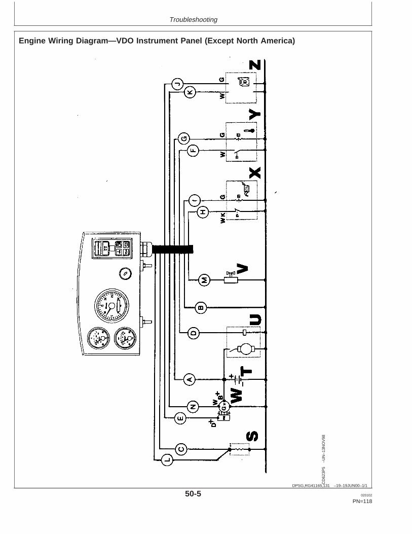
Troubleshooting
DPSG,RG41165,131 –19–19JUN00–1/1
Engine Wiring Diagram—VDO Instrument Panel (Except North America)
CD
623P
5–U
N–1
3NO
V98
50-5 020102
PN=118
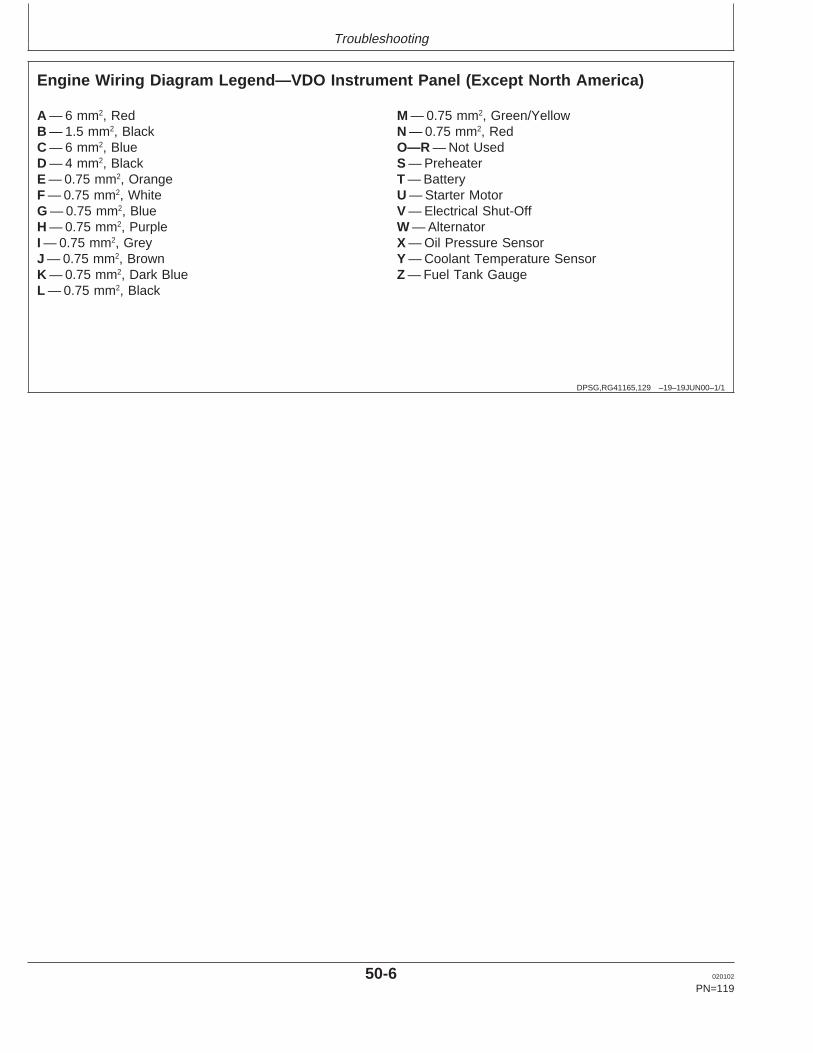
Troubleshooting
DPSG,RG41165,129 –19–19JUN00–1/1
Engine Wiring Diagram Legend—VDO Instrument Panel (Except North America)
A — 6 mm2, RedB — 1.5 mm2, BlackC — 6 mm2, BlueD — 4 mm2, BlackE — 0.75 mm2, OrangeF — 0.75 mm2, WhiteG — 0.75 mm2, BlueH — 0.75 mm2, PurpleI — 0.75 mm2, GreyJ — 0.75 mm2, BrownK — 0.75 mm2, Dark BlueL — 0.75 mm2, Black
M — 0.75 mm2, Green/YellowN — 0.75 mm2, RedO—R — Not UsedS — PreheaterT — BatteryU — Starter MotorV — Electrical Shut-OffW — AlternatorX — Oil Pressure SensorY — Coolant Temperature SensorZ — Fuel Tank Gauge
50-6 020102
PN=119
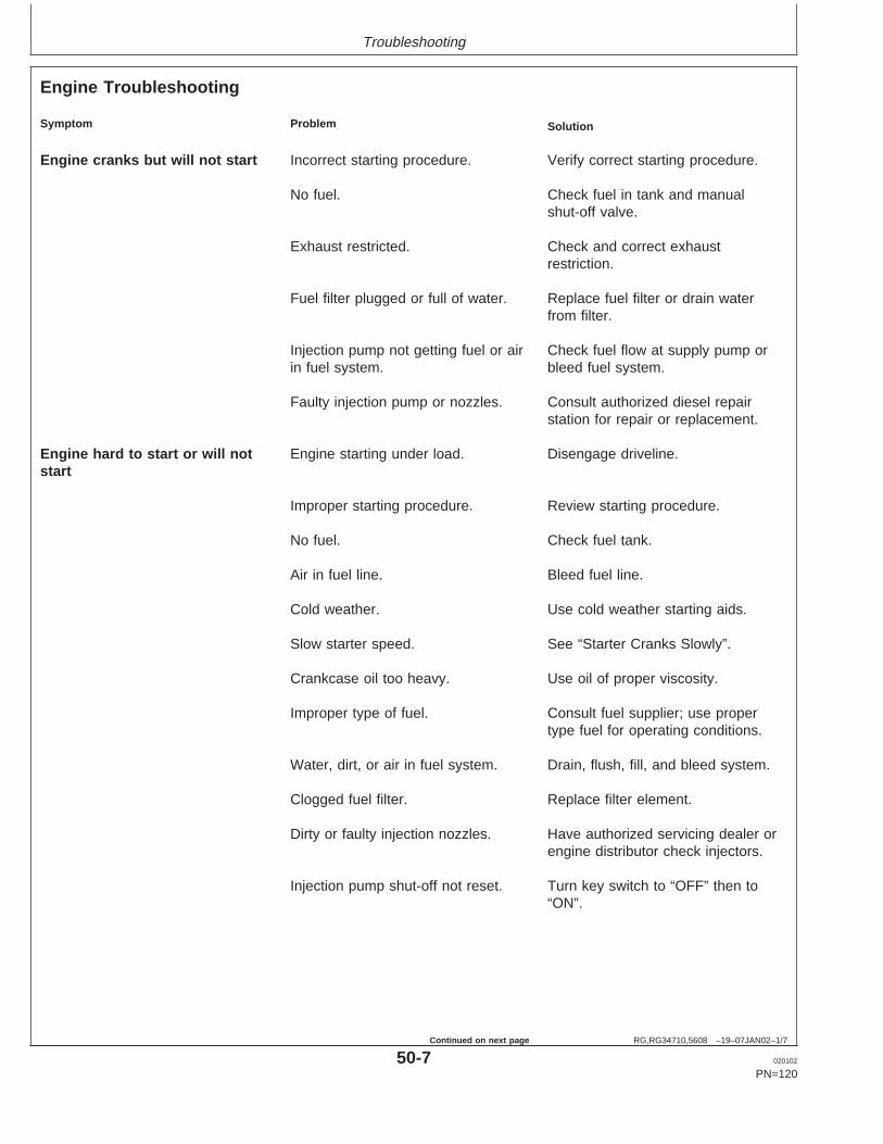
Troubleshooting
RG,RG34710,5608 –19–07JAN02–1/7
Engine Troubleshooting
Symptom Problem Solution
Engine cranks but will not start Incorrect starting procedure. Verify correct starting procedure.
No fuel. Check fuel in tank and manualshut-off valve.
Exhaust restricted. Check and correct exhaustrestriction.
Fuel filter plugged or full of water. Replace fuel filter or drain waterfrom filter.
Injection pump not getting fuel or air Check fuel flow at supply pump orin fuel system. bleed fuel system.
Faulty injection pump or nozzles. Consult authorized diesel repairstation for repair or replacement.
Engine hard to start or will not Engine starting under load. Disengage driveline.start
Improper starting procedure. Review starting procedure.
No fuel. Check fuel tank.
Air in fuel line. Bleed fuel line.
Cold weather. Use cold weather starting aids.
Slow starter speed. See “Starter Cranks Slowly”.
Crankcase oil too heavy. Use oil of proper viscosity.
Improper type of fuel. Consult fuel supplier; use propertype fuel for operating conditions.
Water, dirt, or air in fuel system. Drain, flush, fill, and bleed system.
Clogged fuel filter. Replace filter element.
Dirty or faulty injection nozzles. Have authorized servicing dealer orengine distributor check injectors.
Injection pump shut-off not reset. Turn key switch to “OFF” then to“ON”.
50-7 020102
PN=120
Continued on next page
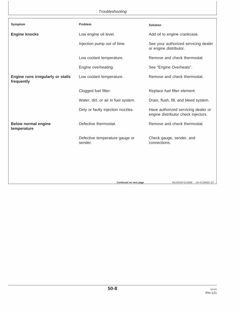
Troubleshooting
RG,RG34710,5608 –19–07JAN02–2/7
Symptom Problem Solution
Engine knocks Low engine oil level. Add oil to engine crankcase.
Injection pump out of time. See your authorized servicing dealeror engine distributor.
Low coolant temperature. Remove and check thermostat.
Engine overheating. See “Engine Overheats”.
Engine runs irregularly or stalls Low coolant temperature. Remove and check thermostat.frequently
Clogged fuel filter. Replace fuel filter element.
Water, dirt, or air in fuel system. Drain, flush, fill, and bleed system.
Dirty or faulty injection nozzles. Have authorized servicing dealer orengine distributor check injectors.
Below normal engine Defective thermostat. Remove and check thermostat.temperature
Defective temperature gauge or Check gauge, sender, andsender. connections.
Continued on next page
50-8 020102
PN=121

Troubleshooting
RG,RG34710,5608 –19–07JAN02–3/7
Symptom Problem Solution
Lack of power Engine overloaded. Reduce load.
Intake air restriction. Service air cleaner.
Clogged fuel filter. Replace filter elements.
Improper type of fuel. Use proper fuel.
Overheated engine. See “Engine Overheats”.
Below normal engine temperature. Remove and check thermostat.
Improper valve clearance. See your authorized servicing dealeror engine distributor.
Dirty or faulty injection nozzles. Have authorized servicing dealer orengine distributor check injectors.
Injection pump out of time. See your authorized servicing dealeror engine distributor.
Turbocharger not functioning. See your authorized servicing dealer(Turbocharger engines only.) or engine distributor.
Leaking exhaust manifold gasket. See your authorized servicing dealeror engine distributor.
Defective aneroid control line. See your authorized servicing dealeror engine distributor.
Restricted fuel hose. Clean or replace fuel hose.
Low fast idle speed. See your authorized servicing dealeror engine distributor.
Low oil pressure Low oil level. Add oil.
Improper type of oil. Drain, fill crankcase with oil of properviscosity and quality.
Continued on next page
50-9 020102
PN=122

Troubleshooting
RG,RG34710,5608 –19–07JAN02–4/7
Symptom Problem Solution
High oil consumption Crankcase oil too light. Use proper viscosity oil.
Oil leaks. Check for leaks in lines, gaskets,and drain plug.
Restricted crankcase vent tube. Clean vent tube.
Defective turbocharger. See your authorized servicing dealeror engine distributor.
Engine emits white smoke Improper type of fuel. Use proper fuel.
Low engine temperature. Warm up engine to normal operatingtemperature.
Defective thermostat. Remove and check thermostat.
Defective injection nozzles. See your authorized servicing dealeror engine distributor.
Engine out of time. See your authorized servicing dealeror engine distributor.
Engine emits black or gray Improper type of fuel. Use proper fuel.exhaust smoke
Clogged or dirty air cleaner. Service air cleaner.
Engine overloaded. Reduce load.
Injection nozzles dirty. See your authorized servicing dealeror engine distributor.
Engine out of time. See your authorized servicing dealeror engine distributor.
Turbocharger not functioning. See your authorized servicing dealeror engine distributor.
Continued on next page
50-10 020102
PN=123

Troubleshooting
RG,RG34710,5608 –19–07JAN02–5/7
Symptom Problem Solution
Engine overheats Engine overloaded. Reduce load.
Low coolant level. Fill radiator to proper level, checkradiator and hoses for looseconnections or leaks.
Faulty radiator cap. Have serviceman check.
Stretched poly-vee belt or defective Check automatic belt tensioner andbelt tensioner. check belts for stretching. Replace
as required.
Low engine oil level. Check oil level. Add oil as required.
Cooling system needs flushing. Flush cooling system.
Defective thermostat. Remove and check thermostat.
Defective temperature gauge or Check water temperature withsender. thermometer and replace, if
necessary.
Incorrect grade of fuel. Use correct grade of fuel.
High fuel consumption Improper type of fuel. Use proper type of fuel.
Clogged or dirty air cleaner. Service air cleaner.
Engine overloaded. Reduce load.
Improper valve clearance. See your authorized servicing dealeror engine distributor.
Injection nozzles dirty. See your authorized servicing dealeror engine distributor.
Engine out of time. See your authorized servicing dealeror engine distributor.
Defective turbocharger. See your authorized servicing dealeror engine distributor.
Low engine temperature. Check thermostat.
50-11 020102
PN=124
Continued on next page
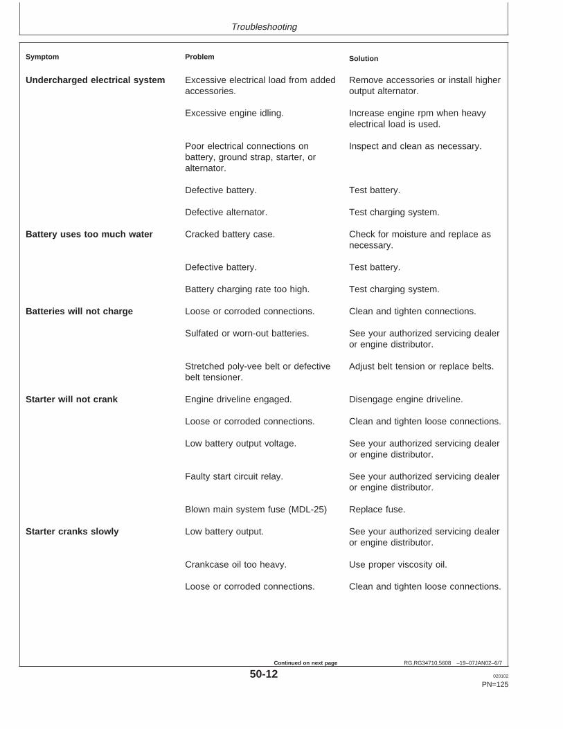
Troubleshooting
RG,RG34710,5608 –19–07JAN02–6/7
Symptom Problem Solution
Undercharged electrical system Excessive electrical load from added Remove accessories or install higheraccessories. output alternator.
Excessive engine idling. Increase engine rpm when heavyelectrical load is used.
Poor electrical connections on Inspect and clean as necessary.battery, ground strap, starter, oralternator.
Defective battery. Test battery.
Defective alternator. Test charging system.
Battery uses too much water Cracked battery case. Check for moisture and replace asnecessary.
Defective battery. Test battery.
Battery charging rate too high. Test charging system.
Batteries will not charge Loose or corroded connections. Clean and tighten connections.
Sulfated or worn-out batteries. See your authorized servicing dealeror engine distributor.
Stretched poly-vee belt or defective Adjust belt tension or replace belts.belt tensioner.
Starter will not crank Engine driveline engaged. Disengage engine driveline.
Loose or corroded connections. Clean and tighten loose connections.
Low battery output voltage. See your authorized servicing dealeror engine distributor.
Faulty start circuit relay. See your authorized servicing dealeror engine distributor.
Blown main system fuse (MDL-25) Replace fuse.
Starter cranks slowly Low battery output. See your authorized servicing dealeror engine distributor.
Crankcase oil too heavy. Use proper viscosity oil.
Loose or corroded connections. Clean and tighten loose connections.
50-12 020102
PN=125
Continued on next page

Troubleshooting
RG,RG34710,5608 –19–07JAN02–7/7
Symptom Problem Solution
Starter and hour meter functions; Blown fuse on magnetic switch. Replace fuse.rest of electrical system does notfunction
Entire electrical system does not Faulty battery connection. Clean and tighten connections.function
Sulfated or worn-out batteries. See your authorized servicing dealeror engine distributor.
Blown main system fuse (MDL-25). Replace fuse.
50-13 020102
PN=126

Storage
RG,RG34710,5610 –19–23NOV01–1/1
Engine Storage Guidelines
1. John Deere engines can be stored outside for up tothree (3) months with no long term preparation IFCOVERED BY WATERPROOF COVERING.
2. John Deere engines can be stored in a standardoverseas shipping container for up to three (3)months with no long term preparation.
3. John Deere engines can be stored inside,warehoused, for up to six (6) months with no longterm preparation.
4. John Deere engines expected to be stored morethan six (6) months, long term storage preparationMUST BE taken. ( See PREPARING ENGINE FORLONG TERM STORAGE, later in this section.)
55-1 020102
PN=127
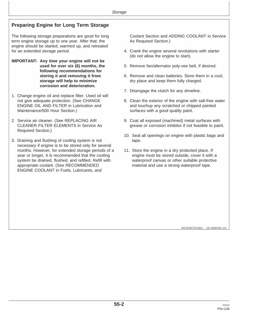
Storage
RG,RG34710,5612 –19–23NOV01–1/1
Preparing Engine for Long Term Storage
The following storage preparations are good for longterm engine storage up to one year. After that, theengine should be started, warmed up, and retreatedfor an extended storage period.
IMPORTANT: Any time your engine will not beused for over six (6) months, thefollowing recommendations forstoring it and removing it fromstorage will help to minimizecorrosion and deterioration.
1. Change engine oil and replace filter. Used oil willnot give adequate protection. (See CHANGEENGINE OIL AND FILTER in Lubrication andMaintenance/500 Hour Section.)
2. Service air cleaner. (See REPLACING AIRCLEANER FILTER ELEMENTS in Service AsRequired Section.)
3. Draining and flushing of cooling system is notnecessary if engine is to be stored only for severalmonths. However, for extended storage periods of ayear or longer, it is recommended that the coolingsystem be drained, flushed, and refilled. Refill withappropriate coolant. (See RECOMMENDEDENGINE COOLANT in Fuels, Lubricants, and
Coolant Section and ADDING COOLANT in ServiceAs Required Section.)
4. Crank the engine several revolutions with starter(do not allow the engine to start).
5. Remove fan/alternator poly-vee belt, if desired.
6. Remove and clean batteries. Store them in a cool,dry place and keep them fully charged.
7. Disengage the clutch for any driveline.
8. Clean the exterior of the engine with salt-free waterand touchup any scratched or chipped paintedsurfaces with a good quality paint.
9. Coat all exposed (machined) metal surfaces withgrease or corrosion inhibitor if not feasible to paint.
10. Seal all openings on engine with plastic bags andtape.
11. Store the engine in a dry protected place. Ifengine must be stored outside, cover it with awaterproof canvas or other suitable protectivematerial and use a strong waterproof tape.
55-2 020102
PN=128

Storage
RG,RG34710,5613 –19–20MAY96–1/1
Removing Engine from Long Term Storage
Refer to the appropriate section for detailed serviceslisted below or have your authorized servicing dealeror engine distributor perform services that you may notbe familiar with.
1. Remove all protective coverings from engine.Unseal all openings in engine and remove coveringfrom electrical systems.
2. Remove the batteries from storage. Install batteries(fully charged) and connect the terminals.
3. Install fan/alternator poly-vee belt if removed.
4. Fill fuel tank.
5. Perform all appropriate prestarting checks. ( SeeDAILY PRESTARTING CHECKS in Lubrication andMaintenance/Daily Section.)
IMPORTANT: DO NOT operate starter more than30 seconds at a time. Wait at least 2minutes for starter to cool beforetrying again.
6. Crank engine for 20 seconds with starter (do notallow the engine to start). Wait 2 minutes and crankengine an additional 20 seconds to assure bearingsurfaces are adequately lubricated.
7. Start engine and run at low idle and no load forseveral minutes. Warm up carefully and check allgauges before placing engine under load.
8. On the first day of operation after storage, checkoverall engine for leaks and check all gauges forcorrect operation.
55-3 020102
PN=129

Specifications
RG,RG34710,5614 –19–08JAN02–1/1
General OEM Engine Specifications—4.5 LEngines
ITEM ENGINE
4045DF120 4045DF150 4045TF120 4045TF150 4045TF220 4045TF250 4045HF120 4045HF150
Number of Cylinders 4 4 4 4 4 4 4 4
Bore 106 mm 106 mm 106 mm 106 mm 106 mm 106 mm 106 mm 106 mm(4.19 in.) (4.19 in.) (4.19 in.) (4.19 in.) (4.19 in.) (4.19 in.) (4.19 in.) (4.19 in.)
Stroke 127 mm 127 mm 127 mm 127 mm 127 mm 127 mm 127 mm 127 mm(5.0 in.) (5.0 in.) (5.0 in.) (5.0 in.) (5.0 in.) (5.0 in.) (5.0 in.) (5.0 in.)
Displacement 4.5 L 4.5 L 4.5 L 4.5 L 4.5 L 4.5 L 4.5 L 4.5 L(276 cu (276 cu (276 cu (276 cu (276 cu (276 cu (276 cu (276 cu
in.) in.) in.) in.) in.) in.) in.) in.)
Compression Ratio 17.8:1 17.6:1 17.0:1 17.0:1 17.0:1 17.0:1 17.0:1 17.0:1
Max. Crank Pressure 0.5 kPa 0.5 kPa 0.5 kPa 0.5 kPa 0.5 kPa 0.5 kPa 0.5 kPa 0.5 kPa(2 H2O) (2 H2O) (2 H2O) (2 H2O) (2 H2O) (2 H2O) (2 H2O) (2 H2O)
Governor Regulation (Industrial) 7—10 % 7—10 % N/A 7—10 % N/A 7—10 % N/A 7—10 %
Governor Regulation (Generator) N/A 5 % 5% 5 % 5% 5 % 5% 5 %
Oil Pressure At Rated Speed, Full 345 kPa 345 kPa 345 kPa 345 kPa 345 kPa 345 kPa 345 kPa 345 kPaLoad (± 15 psi) (50 psi) (50 psi) (50 psi) (50 psi) (50 psi) (50 psi) (50 psi) (50 psi)
Oil Pressure At Low Idle (Minimum) 105 kPa 105 kPa 105 kPa 105 kPa 105 kPa 105 kPa 105 kPa 105 kPa(15 psi) (15 psi) (15 psi) (15 psi) (15 psi) (15 psi) (15 psi) (15 psi)
Length 844.0 mm 861.0 mm 861.0 mm 861.0 mm 861.0 mm 861.0 mm 861.0 mm 861.0 mm(33.2 in.) (33.9 in.) (33.9 in.) (33.9 in.) (33.9 in.) (33.9 in.) (33.9 in.) (33.9 in.)
Width 550 mm 598 mm 598 mm 598 mm 598 mm 598 mm 598 mm 598 mm(21.7 in.) (23.5 in.) (23.5 in.) (23.5 in.) (23.5 in) (23.5 in.) (23.5 in.) (23.5 in.)
Height 871 mm 854 mm 980 mm 980 mm 980 mm 980 mm 980 mm 980 mm(34.3 in.) (33.6 in.) (38.6 in.) (38.6 in.) (38.6 in.) (38.6 in.) (38.6 in.) (38.6 in.)
Weight 429 kg 387 kg 396 kg 396 kg 396 kg 396 kg 396 kg 396 kg(945 lb) (851 lb) (872 lb) (872 lb) (872 lb) (872 lb) (872 lb) (872 lb)
NOTE: Engine models listed with numbers ending in “120” and “220” are emission non-certified. Engines with model numbers ending in “150”and “250” are Tier I emission certified. (Later engines with model numbers ending in “275” are Tier II emission certified with electronic fuelsystems and are covered in another manual, OMRG33324.)
60-1 020102
PN=130
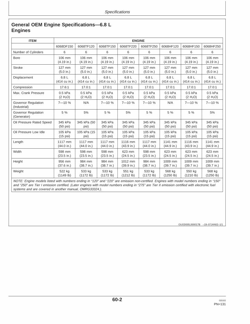
Specifications
OUOD005,000017B –19–07JAN02–1/1
General OEM Engine Specifications—6.8 LEngines
ITEM ENGINE
6068DF150 6068TF120 6068TF150 6068TF220 6068TF250 6068HF120 6068HF150 6068HF250
Number of Cylinders 6 6 6 6 6 6 6 6
Bore 106 mm 106 mm 106 mm 106 mm 106 mm 106 mm 106 mm 106 mm(4.19 in.) (4.19 in.) (4.19 in.) (4.19 in.) (4.19 in.) (4.19 in.) (4.19 in.) (4.19 in.)
Stroke 127 mm 127 mm 127 mm 127 mm 127 mm 127 mm 127 mm 127 mm(5.0 in.) (5.0 in.) (5.0 in.) (5.0 in.) (5.0 in.) (5.0 in.) (5.0 in.) (5.0 in.)
Displacement 6.8 L 6.8 L 6.8 L 6.8 L 6.8 L 6.8 L 6.8 L 6.8 L(414 cu in.) (414 cu in.) (414 cu in.) (414 cu in.) (414 cu in.) (414 cu in.) (414 cu in.) (414 cu in.)
Compression 17.6:1 17.0:1 17.0:1 17.0:1 17.0:1 17.0:1 17.0:1 17.0:1
Max. Crank Pressure 0.5 kPa 0.5 kPa 0.5 kPa 0.5 kPa 0.5 kPa 0.5 kPa 0.5 kPa 0.5 kPa(2 H2O) (2 H2O) (2 H2O) (2 H2O) (2 H2O) (2 H2O) (2 H2O) (2 H2O)
Governor Regulation 7—10 % N/A 7—10 % 7—10 % 7—10 % N/A 7—10 % 7—10 %(Industrial)
Governor Regulation 5 % 5% 5 % 5% 5 % 5 % 5 % 5%(Generator)
Oil Pressure Rated Speed 345 kPa 345 kPa (50 345 kPa 345 kPa 345 kPa 345 kPa 345 kPa 345 kPa(50 psi) psi) (50 psi) (50 psi) (50 psi) (50 psi) (50 psi) (50 psi)
Oil Pressure Low Idle 105 kPa 105 kPa (15 105 kPa 105 kPa 105 kPa 105 kPa 105 kPa 105 kPa(15 psi) psi) (15 psi) (15 psi) (15 psi) (15 psi) (15 psi) (15 psi)
Length 1117 mm 1117 mm 1117 mm 1116 mm 1117 mm 1141 mm 1116 mm 1141 mm(44.0 in.) (44.0 in.) (44.0 in.) (43.9 in.) (44.0 in.) (44.9 in.) (43.9 in.) (44.9 in.)
Width 598 mm 598 mm 598 mm 623 mm 598 mm 623 mm 623 mm 623 mm(23.5 in.) (23.5 in.) (23.5 in.) (24.5 in.) (23.5 in.) (24.5 in.) (24.5 in.) (24.5 in.)
Height 956 mm 984 mm 984 mm 1012 mm 984 mm 1009 mm 1009 mm 1009 mm(37.6 in.) (38.7 in.) (38.7 in.) (39.9 in.) (38.7 in.) (39.7 in.) (39.7 in.) (39.7 in.)
Weight 522 kg 533 kg 533 kg 551 kg 533 kg 568 kg 550 kg 568 kg(1149 lb) (1172 lb) (1172 lb) (1212 lb) (1172 lb) (1250 lb) (1210 lb) (1250 lb)
NOTE: Engine models listed with numbers ending in “120” and “220” are emission non-certified. Engines with model numbers ending in “150”and “250” are Tier I emission certified. (Later engines with model numbers ending in “275” are Tier II emission certified with electronic fuelsystems and are covered in another manual, OMRG33324.).
60-2 020102
PN=131
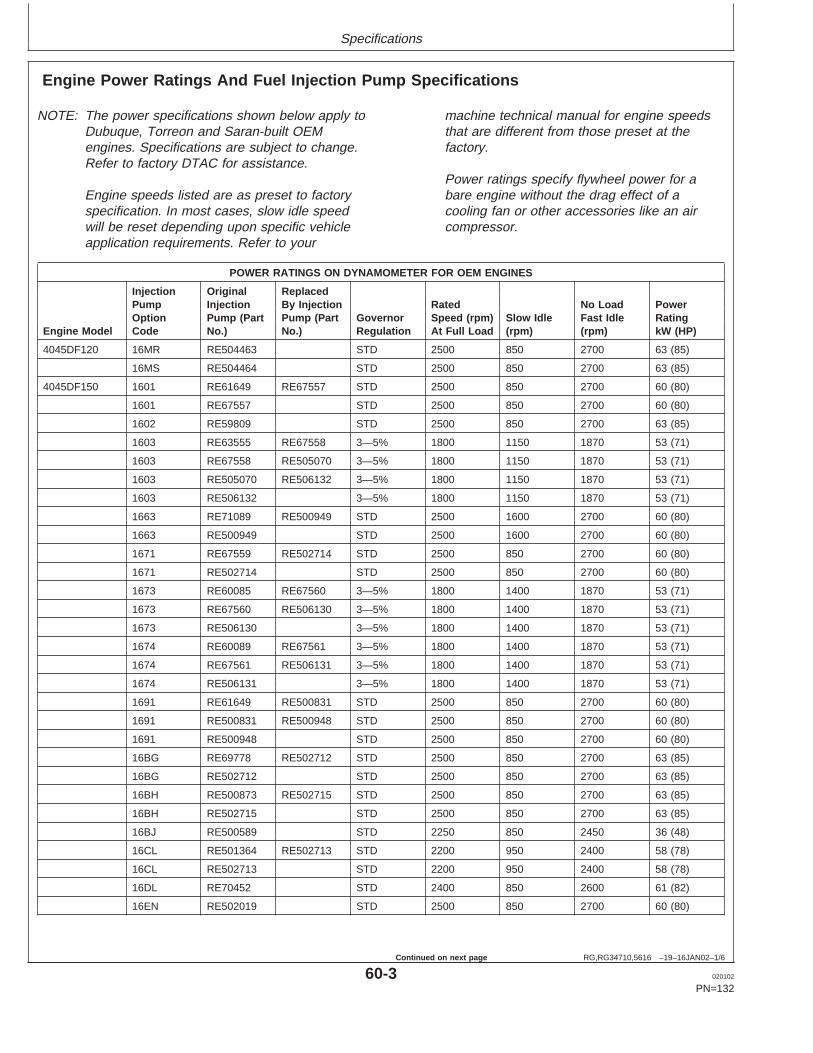
Specifications
RG,RG34710,5616 –19–16JAN02–1/6
Engine Power Ratings And Fuel Injection Pump Specifications
NOTE: The power specifications shown below apply toDubuque, Torreon and Saran-built OEMengines. Specifications are subject to change.Refer to factory DTAC for assistance.
Engine speeds listed are as preset to factoryspecification. In most cases, slow idle speedwill be reset depending upon specific vehicleapplication requirements. Refer to your
machine technical manual for engine speedsthat are different from those preset at thefactory.
Power ratings specify flywheel power for abare engine without the drag effect of acooling fan or other accessories like an aircompressor.
POWER RATINGS ON DYNAMOMETER FOR OEM ENGINES
Injection Original ReplacedPump Injection By Injection Rated No Load PowerOption Pump (Part Pump (Part Governor Speed (rpm) Slow Idle Fast Idle Rating
Engine Model Code No.) No.) Regulation At Full Load (rpm) (rpm) kW (HP)
4045DF120 16MR RE504463 STD 2500 850 2700 63 (85)
16MS RE504464 STD 2500 850 2700 63 (85)
4045DF150 1601 RE61649 RE67557 STD 2500 850 2700 60 (80)
1601 RE67557 STD 2500 850 2700 60 (80)
1602 RE59809 STD 2500 850 2700 63 (85)
1603 RE63555 RE67558 3—5% 1800 1150 1870 53 (71)
1603 RE67558 RE505070 3—5% 1800 1150 1870 53 (71)
1603 RE505070 RE506132 3—5% 1800 1150 1870 53 (71)
1603 RE506132 3—5% 1800 1150 1870 53 (71)
1663 RE71089 RE500949 STD 2500 1600 2700 60 (80)
1663 RE500949 STD 2500 1600 2700 60 (80)
1671 RE67559 RE502714 STD 2500 850 2700 60 (80)
1671 RE502714 STD 2500 850 2700 60 (80)
1673 RE60085 RE67560 3—5% 1800 1400 1870 53 (71)
1673 RE67560 RE506130 3—5% 1800 1400 1870 53 (71)
1673 RE506130 3—5% 1800 1400 1870 53 (71)
1674 RE60089 RE67561 3—5% 1800 1400 1870 53 (71)
1674 RE67561 RE506131 3—5% 1800 1400 1870 53 (71)
1674 RE506131 3—5% 1800 1400 1870 53 (71)
1691 RE61649 RE500831 STD 2500 850 2700 60 (80)
1691 RE500831 RE500948 STD 2500 850 2700 60 (80)
1691 RE500948 STD 2500 850 2700 60 (80)
16BG RE69778 RE502712 STD 2500 850 2700 63 (85)
16BG RE502712 STD 2500 850 2700 63 (85)
16BH RE500873 RE502715 STD 2500 850 2700 63 (85)
16BH RE502715 STD 2500 850 2700 63 (85)
16BJ RE500589 STD 2250 850 2450 36 (48)
16CL RE501364 RE502713 STD 2200 950 2400 58 (78)
16CL RE502713 STD 2200 950 2400 58 (78)
16DL RE70452 STD 2400 850 2600 61 (82)
16EN RE502019 STD 2500 850 2700 60 (80)
60-3 020102
PN=132
Continued on next page

Specifications
RG,RG34710,5616 –19–16JAN02–2/6
POWER RATINGS ON DYNAMOMETER FOR OEM ENGINES
Injection Original ReplacedPump Injection By Injection Rated No Load PowerOption Pump (Part Pump (Part Governor Speed (rpm) Slow Idle Fast Idle Rating
Engine Model Code No.) No.) Regulation At Full Load (rpm) (rpm) kW (HP)
16GB RE502711 STD 2500 850 2700 60 (80)
16GC RE502716 STD 2500 850 2700 60 (80)
16HJ RE500948 STD 2500 1400 2700 60 (80)
16HK RE500949 STD 2500 1600 2700 60 (80)
16HV RE503258 STD 2250 850 2450 36 (48)
16KE RE503560 STD 2500 850 2700 52 (70)
16LM RE502711 STD 2500 850 2700 53 (71)
16LN RE67558 RE505070 3—5% 1800 1150 1870 53 (71)
16LN RE505070 RE506132 3—5% 1800 1150 1870 53 (71)
16LN RE506132 3—5% 1800 1150 1870 53 (71)
16RB RE503729 3—5% 1500 1400 1560 44 (59)
16RC RE504693 3—5% 1500 1400 1560 44 (59)
4045DF151 1663 RE71089 RE500949 STD 2500 1600 2700 60 (80)
1663 RE500949 STD 2500 1600 2700 60 (80)
4045DF152 1601 RE67557 STD 2500 850 2700 60 (80)
16GB RE502711 STD 2500 850 2700 60 (80)
4045DF154 16AY RE500505 STD 2400 850 2600 62 (83)
16JS RE500505 STD 2400 850 2600 62 (83)
4045HF120 16GR RE503050 3—5% 1500 1400 1560 102 (137)
16LW RE503832 3—5% 1500 1400 1560 102 (137)
4045HF150 1610 RE68826 STD 2400 850 2600 104 (140)
1611 RE60237 3—5% 1800 1400 1870 95 (127)
160B RE68827 3—5% 1800 1400 1870 95 (127)
160C RE69588 STD 2400 850 2600 104 (140)
16GR RE503050 3—5% 1500 1150 1560 100 (134)
16LW RE503832 3—5% 1500 1150 1560 100 (134)
16QZ RE503050 3—5% 1800 1400 1870 111 (149)
16RA RE503832 3—5% 1800 1400 1870 111 (149)
4045HF152 16RM RE505959 STD 2400 850 2600 104 (140)
4045HF158 16GR RE503050 3—5% 1500 1150 1560 100 (134)
16LW RE503832 3—5% 1500 1150 1560 100 (134)
16ME RE503739 3—5% 1800 1400 1870 123 (165)
16MF RE504698 RE504966 3—5% 1800 1400 1870 123 (170)
16MF RE504966 3—5% 1800 1400 1870 123 (170)
4045TF120 16MT RE503733 3—5% 1500 1400 1560 70 (94)
16MU RE505050 3—5% 1500 1400 1560 70 (94)
4045TF150 1605 RE61668 RE69781 STD 2500 850 2700 86 (115)
1605 RE69781 STD 2500 850 2700 86 (115)
1606 RE64133 STD 2400 850 2600 93 (125)
1656 RE63610 RE67562 3—5% 1800 1150 1870 75 (100)
1656 RE67562 3—5% 1800 1150 1870 75 (100)
1675 RE60091 RE69782 STD 2500 850 2700 86 (115)
60-4 020102
PN=133
Continued on next page

Specifications
RG,RG34710,5616 –19–16JAN02–3/6
POWER RATINGS ON DYNAMOMETER FOR OEM ENGINES
Injection Original ReplacedPump Injection By Injection Rated No Load PowerOption Pump (Part Pump (Part Governor Speed (rpm) Slow Idle Fast Idle Rating
Engine Model Code No.) No.) Regulation At Full Load (rpm) (rpm) kW (HP)
1675 RE69782 STD 2500 850 2700 86 (115)
1676 RE60093 STD 2500 850 2700 86 (115)
1677 RE60096 RE67563 3—5% 1800 1150 1870 75 (100)
1677 RE67563 3—5% 1800 1150 1870 75 (100)
1692 RE61668 RE500881 STD 2500 1400 2700 86 (115)
1692 RE500881 RE502416 STD 2500 1400 2700 86 (115)
1692 RE502416 STD 2500 1400 2700 86 (115)
1694 RE67863 RE69779 STD 2500 850 2700 75 (100)
1694 RE69779 STD 2500 850 2700 75 (100)
1695 RE69739 RE69780 STD 2500 850 2700 75 (100)
1695 RE69780 STD 2500 850 2700 75 (100)
16AB RE69779 STD 2500 850 2700 75 (100)
16BF RE500848 STD 2200 950 2400 73 (98)
16CE RE501180 STD 2500 850 2700 75 (100)
16CM RE501365 STD 2200 950 2400 66.6 (89)
16GL RE502706 STD 2300 850 2500 78 (105)
16LP RE67562 3—5% 1800 1150 1870 75 (100)
16LZ RE503735 3—5% 1800 1400 1870‘ 70 (94)
16MA RE504696 RE504931 3—5% 1800 1400 1870 82 (110)
16MA RE504931 3—5% 1800 1400 1870 82 (110)
16MT RE503733 RE505050 3—5% 1500 1400 1560 70 (94)
16MT RE505050 3—5% 1500 1400 1560 70 (94)
16MU RE504695 RE505050 3—5% 1500 1400 1560 70 (94)
16MU RE505050 3—5% 1500 1400 1560 70 (94)
16TG RE507941 STD 2000 850 2185 77 (103)
16YJ RE508834 STD 2000 850 2185 77 (103)
4045TF151 1677 RE67563 3—5% 1800 850 1870 75 (100
16CU RE501192 STD 2200 850 2400 79.5 (107)
16NH RE505411 3—5% 1800 1150 2240 75 (100)
4045TF154 1605 RE69781 STD 2500 850 2700 86 (115)
4045TF220 16GQ RE503048 3—5% 1500 1400 1560 83 (111)
16LV RE503830 3—5% 1500 1400 1560 83 (111)
16MV RE503736 3—5% 1800 1400 1870 100 (134)
16MW RE505051 3—5% 1800 1400 1870 100 (134)
16NT RE504465 STD 2500 850 2700 86 (115)
16NU RE504466 STD 2500 850 2700 86 (115)
4045TF250 1606 RE64133 STD 2400 850 2600 93 (125)
1608 RE67564 3—5% 1800 1400 1870 84 (113)
1667 RE59968 STD 2400 850 2600 93 (125)
1682 RE67566 3—5% 1800 1400 1870 84 (113)
1683 RE60124 STD 2400 850 2600 93 (125)
160R RE70941 3—5% 1800 1400 1870 84 (113)
16CV RE501346 STD 2200 950 2400 85 (114)
60-5 020102
PN=134
Continued on next page

Specifications
RG,RG34710,5616 –19–16JAN02–4/6
POWER RATINGS ON DYNAMOMETER FOR OEM ENGINES
Injection Original ReplacedPump Injection By Injection Rated No Load PowerOption Pump (Part Pump (Part Governor Speed (rpm) Slow Idle Fast Idle Rating
Engine Model Code No.) No.) Regulation At Full Load (rpm) (rpm) kW (HP)
16GQ RE503048 3—5% 1500 1150 1560 83 (111)
16LQ RE67564 3—5% 1800 1400 1870 84 (113)
16LV RE503830 3—5% 1500 1150 1560 83 (111)
16MB RE503737 3—5% 1800 1400 1870 91(122)
16MC RE504932 3—5% 1800 1400 1870 91 (122)
161C RE507525 3—5% 1800 1400 1870 100 (134)
161D RE507526 3—5% 1800 1400 1870 100 (134)
4045TF251 1606 RE64133 STD 2400 850 2600 93 (125)
6068DF150 1613 RE59861 STD 2500 850 2700 93 (125)
1678 RE60101 STD 2500 850 2700 93 (125)
16LR RE59861 STD 2500 850 2700 93 (125)
6068HF120 16GT RE503051 3—5% 1500 1400 1560 155 (208)
16LY RE503834 3—5% 1500 1400 1560 155 (208)
16RL RE506085 3—5% 2100 950 2200 197 (264)
16SJ RE506627 3—5% 2100 950 2200 197 (264)
16TP RE506883 3—5% 1500 1150 1560 183 (245)
16TQ RE506884 3—5% 1500 1150 1560 183 (245)
16ZQ RE509428 3—5% 2100 950 2200 197 (264)
16ZR RE509429 3—5% 2100 950 2200 197 (264)
6068HF150 1621 RE66575 STD 2400 850 2600 157 (210)
160D RE69589 STD 2400 850 2600 157 (210)
16CY RE501345 STD 2200 1350 2400 143 (192)
16GT RE503051 3—5% 1500 1400 1560 153 (205)
16LY RE503836 3—5% 1500 1400 1560 153 (205)
16ML RE503746 3—5% 1800 1400 1870 187 (251)
16MM RE504702 RE505049 3—5% 1800 1400 1870 187 (251)
16MM RE505049 3—5% 1800 1400 1870 187 (251)
16QV RE503051 3—5% 1800 1400 1870 166 (223)
16QW RE503836 3—5% 1800 1400 1870 166 (223)
6068HF250 1622 RE59521a STD 2400 850 2600 168 (225)
1623 RE66761a 3—5% 1800 1400 1870 148 (198)
16YH RE59969 STD 2400 850 2600 138 (185)
6068TF120 16MX RE503740 3—5% 1500 1400 1560 105 (141)
16MY RE505052 3—5% 1500 1400 1560 105 (141)
6068TF150 1614 RE61669 RE69789 STD 2500 850 2700 127 (170)
1614 RE69789 STD 2500 850 2700 127 (170)
1680 RE60105 RE69790 STD 2500 850 2700 127 (170)
1680 RE69790 STD 2500 850 2700 127 (170)
1681 RE67571 3—5% 1800 1150 1870 112 (150)
1688 RE67572 3—5% 1800 1150 1870 112 (150)
1696 RE67864 RE69787 STD 2500 850 2700 116 (155)aIn-line fuel injection pump.
60-6 020102
PN=135
Continued on next page
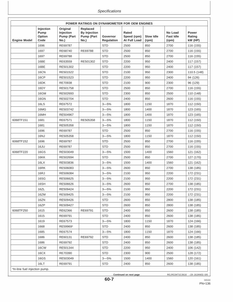
Specifications
RG,RG34710,5616 –19–16JAN02–5/6
POWER RATINGS ON DYNAMOMETER FOR OEM ENGINES
Injection Original ReplacedPump Injection By Injection Rated No Load PowerOption Pump (Part Pump (Part Governor Speed (rpm) Slow Idle Fast Idle Rating
Engine Model Code No.) No.) Regulation At Full Load (rpm) (rpm) kW (HP)
1696 RE69787 STD 2500 850 2700 116 (155)
1697 RE68740 RE69788 STD 2500 850 2700 116 (155)
1697 RE69788 STD 2500 850 2700 116 (155)
16BE RE63559 RE501302 STD 2200 950 2400 117 (157)
16BE RE501302 STD 2200 950 2400 117 (157)
16CN RE501522 STD 2100 950 2300 110.5 (148)
16CP RE501523 STD 2200 950 2400 94 (126)
16DK RE70938 STD 2100 900 2300 96 (129)
16DY RE501758 STD 2500 850 2700 116 (155)
16GM RE502693 STD 2300 850 2500 110 (148)
16GN RE502704 STD 2400 850 2600 116 (155)
16LS RE67572 3—5% 1800 1150 1870 112 (150)
16MG RE503742 3—5% 1800 1400 1870 123 (165)
16MH RE504967 3—5% 1800 1400 1870 123 (165)
6068TF151 1681 RE67571 RE505358 3—5% 1800 1150 1870 112 (150)
1681 RE505358 3—5% 1800 1150 1870 112 (150)
1696 RE69787 STD 2500 850 2700 116 (155)
16NJ RE505358 3—5% 1800 1150 1870 112 (150)
6068TF152 1696 RE69787 STD 2500 850 2700 116 (155)
16JU RE69787 STD 2500 850 2700 116 (155)
6068TF220 16GS RE503049 3—5% 1500 1400 1560 121 (162)
16KK RE502694 STD 2500 850 2700 127 (170)
16LX RE503836 3—5% 1500 1400 1560 121 (162)
16RK RE506083 3—5% 2600 850 2700 138 (185)
16RJ RE506084 3—5% 2100 950 2200 172 (231)
16SG RE506625 3—5% 2100 950 2200 172 (231)
16SH RE506626 3—5% 2600 850 2700 138 (185)
16ZL RE509424 3—5% 2100 950 2200 172 (231)
16ZM RE509425 3—5% 2100 950 2200 172 (231)
16ZN RE509426 STD 2600 850 2800 138 (185)
16ZP RE509427 STD 2600 850 2800 138 (185)
6068TF250 1615 RE62366 RE69791 STD 2400 850 2600 138 (185)
1615 RE69791 STD 2400 850 2600 138 (185)
1619 RE67573 3—5% 1800 1150 1870 124 (166)
1668 RE59969a STD 2400 850 2600 138 (185)
1685 RE67574 3—5% 1800 1150 1870 124 (166)
1686 RE60131 RE69792 STD 2400 850 2600 138 (185)
1686 RE69792 STD 2400 850 2600 138 (185)
16CW RE501344 STD 2200 950 2400 106 (142)
16CX RE70390 STD 2300 900 2500 128 (172)
16GS RE503049 3—5% 1500 1400 1560 120 (161)
16LT RE69791 STD 2400 850 2600 138 (185)aIn-line fuel injection pump.
60-7 020102
PN=136
Continued on next page

Specifications
RG,RG34710,5616 –19–16JAN02–6/6
POWER RATINGS ON DYNAMOMETER FOR OEM ENGINES
Injection Original ReplacedPump Injection By Injection Rated No Load PowerOption Pump (Part Pump (Part Governor Speed (rpm) Slow Idle Fast Idle Rating
Engine Model Code No.) No.) Regulation At Full Load (rpm) (rpm) kW (HP)
16LU RE67573 3—5% 1800 1150 1870 124 (166)
16LX RE503834 3—5% 1500 1400 1560 120 (161)
16MJ RE503744 3—5% 1800 1400 1870 142 (190)
16MK RE504701 RE504968 3—5% 1800 1400 1870 142 (190)
16MK RE504968 3—5% 1800 1400 1870 142 (190)
6068TF251 1615 RE62366 STD 2400 850 2600 138 (185)
RG,RG34710,5617 –19–07JAN02–1/4
Engine Crankcase Oil Fill Quantities
To determine the option code for the oil fill quantity ofyour engine, refer to the engine option code labelaffixed to the rocker arm cover. The first two digits ofthe code (19) identify the oil pan option group. The lasttwo digits of each code identify the specific oil pan onyour engine.
The following table lists engine crankcase oil fillquantities for each “19__” option code for theseengines.
Continued on next page
60-8 020102
PN=137
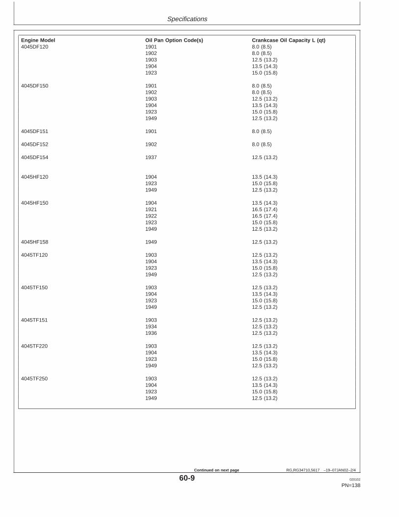
Specifications
RG,RG34710,5617 –19–07JAN02–2/4
Engine Model Oil Pan Option Code(s) Crankcase Oil Capacity L (qt)4045DF120 1901 8.0 (8.5)
1902 8.0 (8.5)1903 12.5 (13.2)1904 13.5 (14.3)1923 15.0 (15.8)
4045DF150 1901 8.0 (8.5)1902 8.0 (8.5)1903 12.5 (13.2)1904 13.5 (14.3)1923 15.0 (15.8)1949 12.5 (13.2)
4045DF151 1901 8.0 (8.5)
4045DF152 1902 8.0 (8.5)
4045DF154 1937 12.5 (13.2)
4045HF120 1904 13.5 (14.3)1923 15.0 (15.8)1949 12.5 (13.2)
4045HF150 1904 13.5 (14.3)1921 16.5 (17.4)1922 16.5 (17.4)1923 15.0 (15.8)1949 12.5 (13.2)
4045HF158 1949 12.5 (13.2)
4045TF120 1903 12.5 (13.2)1904 13.5 (14.3)1923 15.0 (15.8)1949 12.5 (13.2)
4045TF150 1903 12.5 (13.2)1904 13.5 (14.3)1923 15.0 (15.8)1949 12.5 (13.2)
4045TF151 1903 12.5 (13.2)1934 12.5 (13.2)1936 12.5 (13.2)
4045TF220 1903 12.5 (13.2)1904 13.5 (14.3)1923 15.0 (15.8)1949 12.5 (13.2)
4045TF250 1903 12.5 (13.2)1904 13.5 (14.3)1923 15.0 (15.8)1949 12.5 (13.2)
60-9 020102
PN=138
Continued on next page

Specifications
RG,RG34710,5617 –19–07JAN02–3/4
Engine Model Oil Pan Option Code(s) Crankcase Oil Capacity L (qt)4045TF251 1904 13.5 (14.3)
6068DF150 1907 19.5 (20.6)1908 19.0 (20.1)1909 19.0 (20.1)1944 20.0 (21.1)1948 20.0 (21.1)1950 20.0 (21.1)
6068TF120 1907 19.0 (20.1)1908 19.0 (20.1)1909 19.0 (20.1)1944 20.0 (21.1)1956 18.0 (19.0)
6068TF150 1907 19.0 (20.1)1908 19.0 (20.1)1909 19.0 (20.1)1944 20.0 (21.1)1948 20.0 (21.1)1950 20.0 (21.1)1956 18.0 (19.0)
6068TF151 1907 19.0 (20.1)1909 19.0 (20.1)1944 20.0 (21.1)
6068TF152 1909 19.0 (20.1)
6068TF159 1963 21.5 (22.7)
6068TF220 1907 19.0 (20.1)1908 19.0 (20.1)1909 19.0 (20.1)1944 20.0 (21.1)1948 20.0 (21.1)1950 20.0 (21.1)1956 18.0 (19.0)
6068TF250 1907 19.0 (20.1)1908 19.0 (20.1)1909 19.0 (20.1)1924 25.0 (26.4)1944 20.0 (21.1)1948 20.0 (21.1)1950 20.0 (21.1)1956 18.0 (19.0)
6068TF251 1909 19.0 (20.1)
6068HF120 1907 19.0 (20.1)1908 19.0 (20.1)1909 19.0 (20.1)1950 20.0 (21.1)1956 18.0 (19.0)
60-10 020102
PN=139
Continued on next page
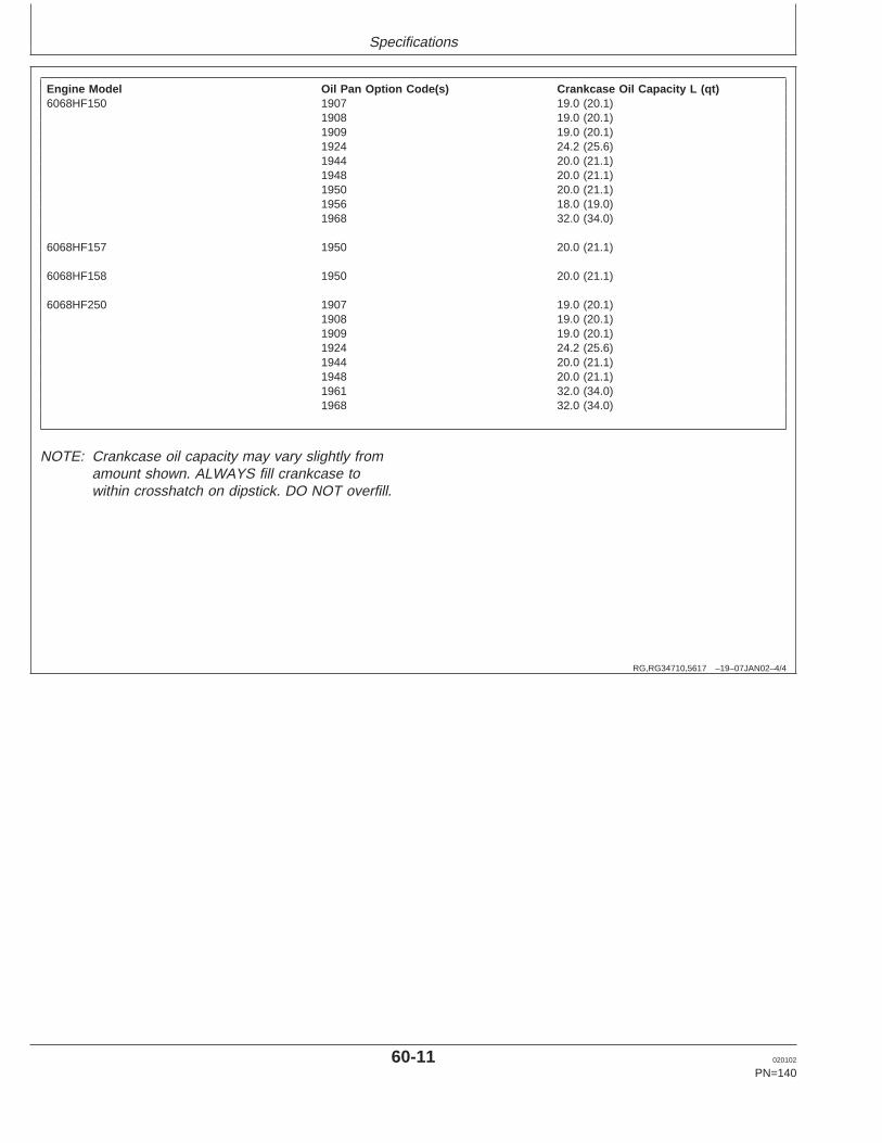
Specifications
RG,RG34710,5617 –19–07JAN02–4/4
Engine Model Oil Pan Option Code(s) Crankcase Oil Capacity L (qt)6068HF150 1907 19.0 (20.1)
1908 19.0 (20.1)1909 19.0 (20.1)1924 24.2 (25.6)1944 20.0 (21.1)1948 20.0 (21.1)1950 20.0 (21.1)1956 18.0 (19.0)1968 32.0 (34.0)
6068HF157 1950 20.0 (21.1)
6068HF158 1950 20.0 (21.1)
6068HF250 1907 19.0 (20.1)1908 19.0 (20.1)1909 19.0 (20.1)1924 24.2 (25.6)1944 20.0 (21.1)1948 20.0 (21.1)1961 32.0 (34.0)1968 32.0 (34.0)
NOTE: Crankcase oil capacity may vary slightly fromamount shown. ALWAYS fill crankcase towithin crosshatch on dipstick. DO NOT overfill.
60-11 020102
PN=140

Specifications
DX,TORQ1 –19–01OCT99–1/1
Unified Inch Bolt and Cap Screw Torque Values
TO
RQ
1A–U
N–2
7SE
P99
Top, SAE Grade and Head Markings; Bottom, SAE Grade and Nut Markings
Grade 1 (No Mark) Grade 2a (No Mark) Grade 5, 5.1 or 5.2 Grade 8 or 8.2
Size Lubricatedb Dryc Lubricatedb Dryc Lubricatedb Dryc Lubricatedb Dryc
N•m(lb-ft) N•m(lb-ft) N•m(lb-ft) N•m(lb-ft) N•m(lb-ft) N•m(lb-ft) N•m(lb-ft) N•m(lb-ft)
1/4 3.8 (2.8) 4.7 (3.5) 6 (4.4) 7.5 (5.5) 9.5 (7) 12 (9) 13.5 (10) 17 (12.5)
5/16 7.7 (5.7) 9.8 (7.2) 12 (9) 15.5 (11.5) 19.5 (14.5) 25 (18.5) 28 (20.5) 35 (26)
3/8 13.5 (10) 17.5 (13) 22 (16) 27.5 (20) 35 (26) 44 (32.5) 49 (36) 63 (46)
7/16 22 (16) 28 (20.5) 35 (26) 44 (32.5) 56 (41) 70 (52) 80 (59) 100 (74)
1/2 34 (25) 42 (31) 53 (39) 67 (49) 85 (63) 110 (80) 120 (88) 155 (115)
9/16 48 (35.5) 60 (45) 76 (56) 95 (70) 125 (92) 155 (115) 175 (130) 220 (165)
5/8 67 (49) 85 (63) 105 (77) 135 (100) 170 (125) 215 (160) 240 (175) 305 (225)
3/4 120 (88) 150 (110) 190 (140) 240 (175) 300 (220) 380 (280) 425 (315) 540 (400)
7/8 190 (140) 240 (175) 190 (140) 240 (175) 490 (360) 615 (455) 690 (510) 870 (640)
1 285 (210) 360 (265) 285 (210) 360 (265) 730 (540) 920 (680) 1030 (760) 1300 (960)
1-1/8 400 (300) 510 (375) 400 (300) 510 (375) 910 (670) 1150 (850) 1450 (1075) 1850 (1350)
1-1/4 570 (420) 725 (535) 570 (420) 725 (535) 1280 (945) 1630 (1200) 2050 (1500) 2600 (1920)
1-3/8 750 (550) 950 (700) 750 (550) 950 (700) 1700 (1250) 2140 (1580) 2700 (2000) 3400 (2500)
1-1/2 990 (730) 1250 (930) 990 (730) 1250 (930) 2250 (1650) 2850 (2100) 3600 (2650) 4550 (3350)a Grade 2 applies for hex cap screws (not hex bolts) up to 6 in. (152 mm) long. Grade 1 applies for hex cap screws over 6 in. (152 mm) long,and for all other types of bolts and screws of any length.b "Lubricated" means coated with a lubricant such as engine oil, or fasteners with phosphate and oil coatings.c "Dry" means plain or zinc plated without any lubrication.
DO NOT use these values if a different torque value or tightening Make sure fastener threads are clean and that you properly startprocedure is given for a specific application. Torque values listed are thread engagement. This will prevent them from failing whenfor general use only. Check tightness of fasteners periodically. tightening.
Shear bolts are designed to fail under predetermined loads. Always Tighten plastic insert or crimped steel-type lock nuts to approximatelyreplace shear bolts with identical grade. 50 percent of the dry torque shown in the chart, applied to the nut,
not to the bolt head. Tighten toothed or serrated-type lock nuts to thefull torque value.
Fasteners should be replaced with the same or higher grade. Ifhigher grade fasteners are used, these should only be tightened tothe strength of the original.
60-12 020102
PN=141

Specifications
DX,TORQ2 –19–01OCT99–1/1
Metric Bolt and Cap Screw Torque Values
TO
RQ
2–U
N–0
7SE
P99
Top, Property Class and Head Markings; Bottom, Property Class and Nut Markings
Class 4.8 Class 8.8 or 9.8 Class 10.9 Class 12.9
Size Lubricateda Dryb Lubricateda Dryb Lubricateda Dryb Lubricateda Dryb
N•m(lb-ft) N•m(lb-ft) N•m(lb-ft) N•m(lb-ft) N•m(lb-ft) N•m(lb-ft) N•m(lb-ft) N•m(lb-ft)
M6 4.7 (3.5) 6 (4.4) 9 (6.6) 11.5 (8.5) 13 (9.5) 16.5 (12.2) 15.5 (11.5) 19.5 (14.5)
M8 11.5 (8.5) 14.5 (10.7) 22 (16) 28 (20.5) 32 (23.5) 40 (29.5) 37 (27.5) 47 (35)
M10 23 (17) 29 (21) 43 (32) 55 (40) 63 (46) 80 (59) 75 (55) 95 (70)
M12 40 (29.5) 50 (37) 75 (55) 95 (70) 110 (80) 140 (105) 130 (95) 165 (120)
M14 63 (46) 80 (59) 120 (88) 150 (110) 175 (130) 220 (165) 205 (150) 260 (190)
M16 100 (74) 125 (92) 190 (140) 240 (175) 275 (200) 350 (255) 320 (235) 400 (300)
M18 135 (100) 170 (125) 265 (195) 330 (245) 375 (275) 475 (350) 440 (325) 560 (410)
M20 190 (140) 245 (180) 375 (275) 475 (350) 530 (390) 675 (500) 625 (460) 790 (580)
M22 265 (195) 330 (245) 510 (375) 650 (480) 725 (535) 920 (680) 850 (625) 1080 (800)
M24 330 (245) 425 (315) 650 (480) 820 (600) 920 (680) 1150 (850) 1080 (800) 1350 (1000)
M27 490 (360) 625 (460) 950 (700) 1200 (885) 1350 (1000) 1700 (1250) 1580 (1160) 2000 (1475)
M30 660 (490) 850 (625) 1290 (950) 1630 (1200) 1850 (1350) 2300 (1700) 2140 (1580) 2700 (2000)
M33 900 (665) 1150 (850) 1750 (1300) 2200 (1625) 2500 (1850) 3150 (2325) 2900 (2150) 3700 (2730)
M36 1150 (850) 1450 (1075) 2250 (1650) 2850 (2100) 3200 (2350) 4050 (3000) 3750 (2770) 4750 (3500)a "Lubricated" means coated with a lubricant such as engine oil, or fasteners with phosphate and oil coatings.b "Dry" means plain or zinc plated without any lubrication.
DO NOT use these values if a different torque value or tightening Make sure fastener threads are clean and that you properly startprocedure is given for a specific application. Torque values listed are thread engagement. This will prevent them from failing whenfor general use only. Check tightness of fasteners periodically. tightening.
Shear bolts are designed to fail under predetermined loads. Always Tighten plastic insert or crimped steel-type lock nuts to approximatelyreplace shear bolts with identical property class. 50 percent of the dry torque shown in the chart, applied to the nut,
not to the bolt head. Tighten toothed or serrated-type lock nuts to thefull torque value.
Fasteners should be replaced with the same or higher property class.If higher property class fasteners are used, these should only betightened to the strength of the original.
60-13 020102
PN=142
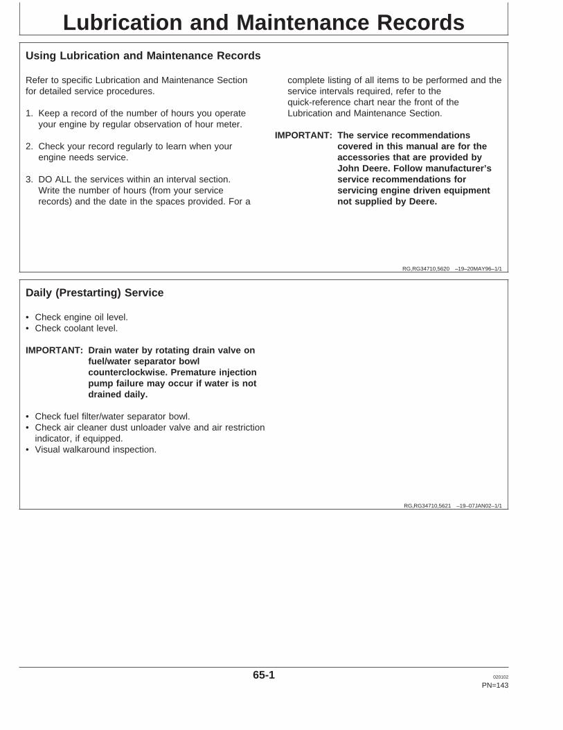
Lubrication and Maintenance Records
RG,RG34710,5620 –19–20MAY96–1/1
Using Lubrication and Maintenance Records
Refer to specific Lubrication and Maintenance Sectionfor detailed service procedures.
1. Keep a record of the number of hours you operateyour engine by regular observation of hour meter.
2. Check your record regularly to learn when yourengine needs service.
3. DO ALL the services within an interval section.Write the number of hours (from your servicerecords) and the date in the spaces provided. For a
complete listing of all items to be performed and theservice intervals required, refer to thequick-reference chart near the front of theLubrication and Maintenance Section.
IMPORTANT: The service recommendationscovered in this manual are for theaccessories that are provided byJohn Deere. Follow manufacturer’sservice recommendations forservicing engine driven equipmentnot supplied by Deere.
RG,RG34710,5621 –19–07JAN02–1/1
Daily (Prestarting) Service
• Check engine oil level.• Check coolant level.
IMPORTANT: Drain water by rotating drain valve onfuel/water separator bowlcounterclockwise. Premature injectionpump failure may occur if water is notdrained daily.
• Check fuel filter/water separator bowl.• Check air cleaner dust unloader valve and air restriction
indicator, if equipped.• Visual walkaround inspection.
65-1 020102
PN=143

Lubrication and Maintenance Records
RG,RG34710,5623 –19–07JAN02–1/1
250 Hour/6 Month Service
• Change engine oil and filter.1
• Service fire extinguisher.• Service battery.• Check automatic belt tensioner and belt wear.
Hours
Date
Hours
Date
Hours
Date
Hours
Date
Hours
Date
Hours
Date
Hours
Date
Hours
Date
1If John Deere PLUS-50 oil is used along with a John Deere oil filter,the oil and filter change interval may be extended by 50 percent toevery 375 hours.
65-2 020102
PN=144
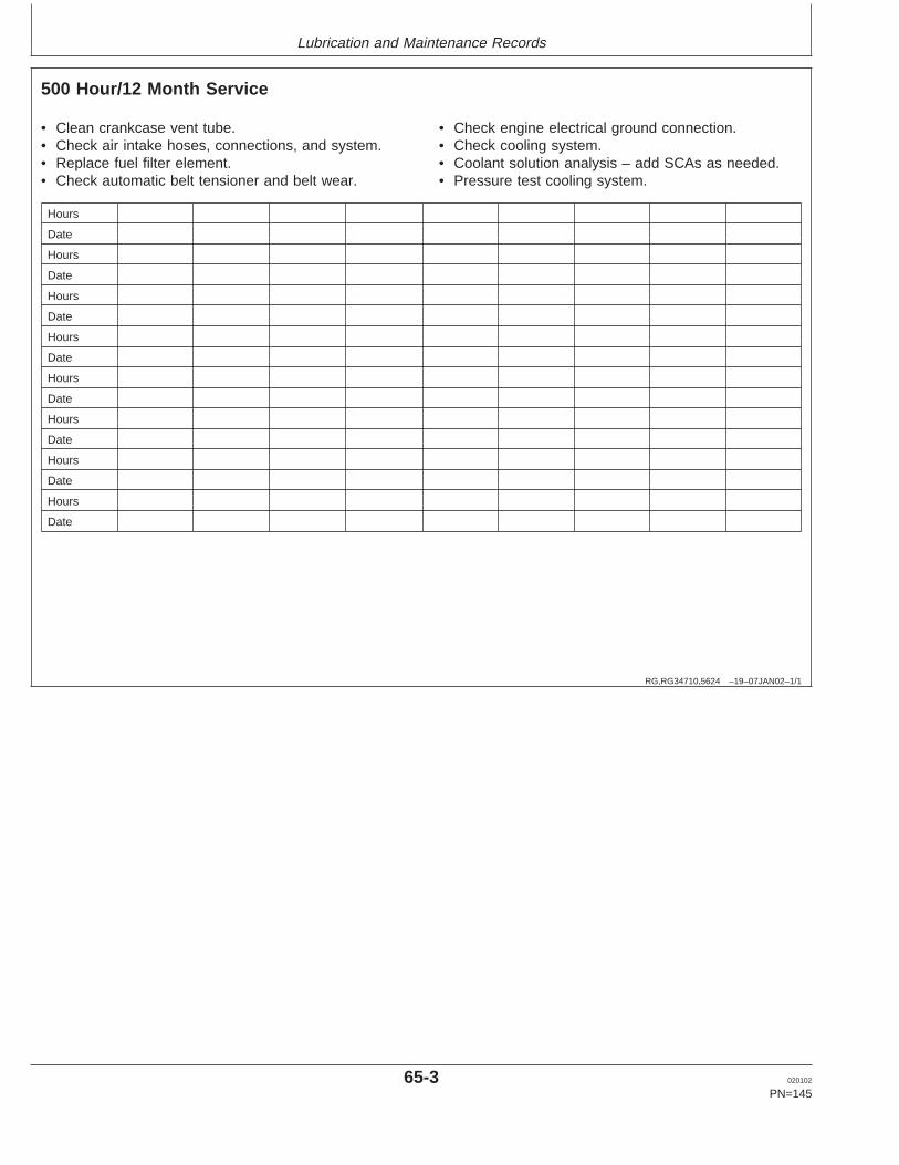
Lubrication and Maintenance Records
RG,RG34710,5624 –19–07JAN02–1/1
500 Hour/12 Month Service
• Clean crankcase vent tube.• Check air intake hoses, connections, and system.• Replace fuel filter element.• Check automatic belt tensioner and belt wear.
• Check engine electrical ground connection.• Check cooling system.• Coolant solution analysis – add SCAs as needed.• Pressure test cooling system.
Hours
Date
Hours
Date
Hours
Date
Hours
Date
Hours
Date
Hours
Date
Hours
Date
Hours
Date
65-3 020102
PN=145
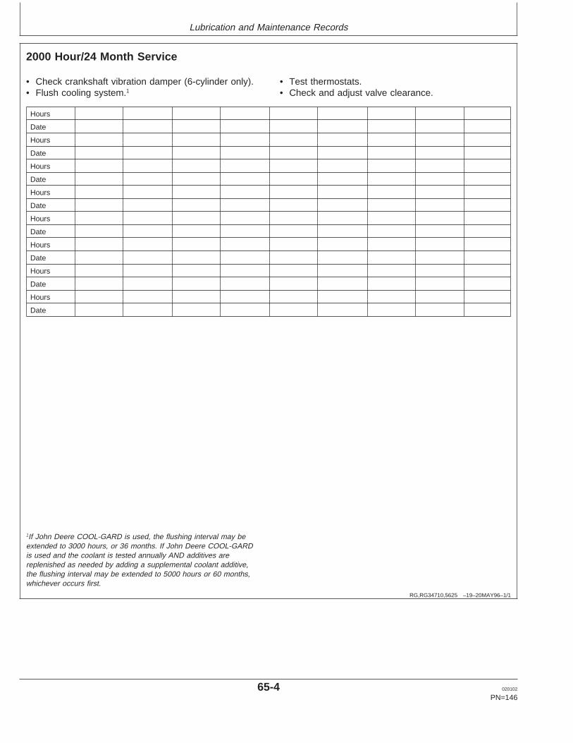
Lubrication and Maintenance Records
RG,RG34710,5625 –19–20MAY96–1/1
2000 Hour/24 Month Service
• Check crankshaft vibration damper (6-cylinder only).• Flush cooling system.1
• Test thermostats.• Check and adjust valve clearance.
Hours
Date
Hours
Date
Hours
Date
Hours
Date
Hours
Date
Hours
Date
Hours
Date
Hours
Date
1If John Deere COOL-GARD is used, the flushing interval may beextended to 3000 hours, or 36 months. If John Deere COOL-GARDis used and the coolant is tested annually AND additives arereplenished as needed by adding a supplemental coolant additive,the flushing interval may be extended to 5000 hours or 60 months,whichever occurs first.
65-4 020102
PN=146

Lubrication and Maintenance Records
RG,RG34710,5627 –19–07JAN02–1/1
Service as Required
• Add coolant• Service air cleaner.• Replace poly-vee belts.• Check fuses• Bleed fuel system
Hours
Date
Hours
Date
Hours
Date
Hours
Date
Hours
Date
Hours
Date
Hours
Date
Hours
Date
65-5 020102
PN=147
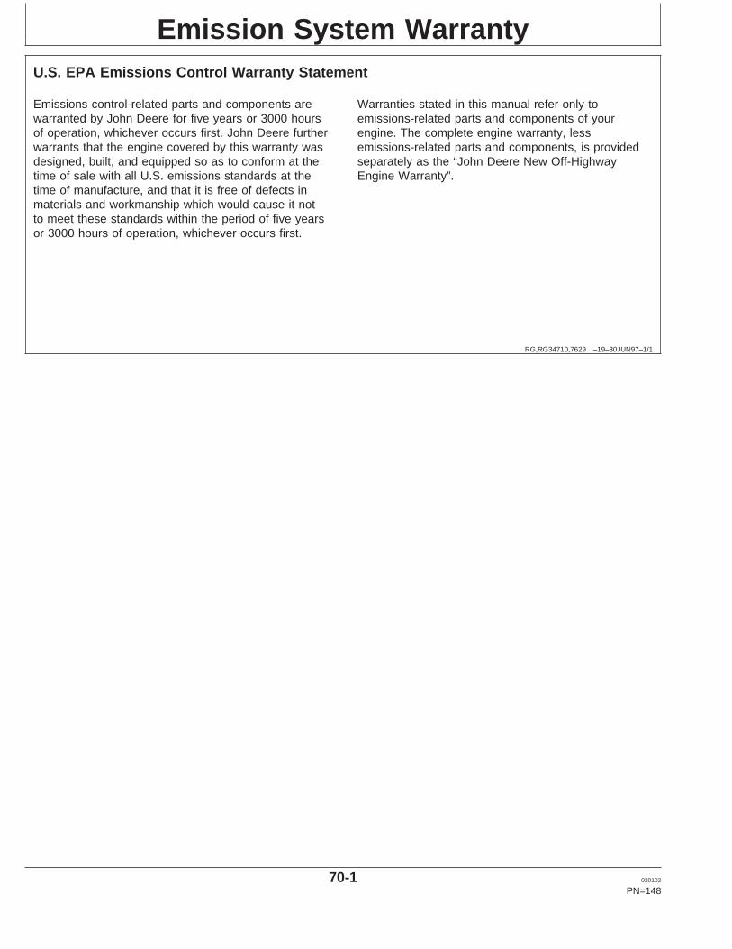
Emission System Warranty
RG,RG34710,7629 –19–30JUN97–1/1
U.S. EPA Emissions Control Warranty Statement
Emissions control-related parts and components arewarranted by John Deere for five years or 3000 hoursof operation, whichever occurs first. John Deere furtherwarrants that the engine covered by this warranty wasdesigned, built, and equipped so as to conform at thetime of sale with all U.S. emissions standards at thetime of manufacture, and that it is free of defects inmaterials and workmanship which would cause it notto meet these standards within the period of five yearsor 3000 hours of operation, whichever occurs first.
Warranties stated in this manual refer only toemissions-related parts and components of yourengine. The complete engine warranty, lessemissions-related parts and components, is providedseparately as the “John Deere New Off-HighwayEngine Warranty”.
70-1 020102
PN=148

Emission System Warranty
DPSG,RG41165,133 –19–10JUL00–1/1
Emissions Control System Certification Label
RG
1194
0–U
N–1
7OC
T01
Emissions Label
CAUTION: Statutes providing severe penaltiesfor tampering with emissions controls mayapply to the user or dealer.
The emissions warranty described below applies only tothose engines marketed by John Deere that have beencertified by the United States Environmental ProtectionAgency (EPA) and/or California Air Resources Board(CARB); and used in the United States and Canada innon-road mobile (self-propelled or portable/transportable1)equipment. The presence of an emissions label like theone shown signifies that the engine has been certifiedwith the EPA and/or CARB. The EPA and CARBwarranties only apply to new engines having thecertification label affixed to the engine and sold as statedabove in the geographic areas. The presence of an EUnumber in the third line of the label signifies that theengine has been certified with the European Unioncountries per Directive 97/68/EC. The emissions warrantydoes not apply to the EU countries.
NOTE: The hp/kW rating on the engine emissionscertification label specifies the gross enginehp/kW, which is flywheel power without fan. Inmost applications this will not be the same ratingas the advertised vehicle hp/kW rating.
1Equipment moved at least once every 12 months.
70-2 020102
PN=149

John Deere Service Literature Available
DPSG,RG41165,134 –19–10JUL00–1/1
Technical Information
RG
9262
–UN
–16M
AR
98
Parts Catalogs
RG
9260
–UN
–16M
AR
98
Operator Manuals
RG
9261
–UN
–16M
AR
98
Component Technical ManualsT
S16
63–U
N–1
0OC
T97
Fundamental Manuals
Technical information is available from John Deere. Someof this information is available in electronic as well asprinted form. Order from your John Deere dealer or call1-800-522-7448. Please have available the modelnumber, serial number, and name of the product.
Available information includes:
• PARTS CATALOGS list service parts available for yourmachine with exploded view illustrations to help youidentify the correct parts. It is also useful in assemblingand disassembling.
• OPERATOR’S MANUALS providing safety, operating,maintenance, and service information. These manualsand safety signs on your machine may also be availablein other languages.
• OPERATOR’S VIDEO TAPES showing highlights ofsafety, operating, maintenance, and service information.These tapes may be available in multiple languagesand formats.
• TECHNICAL MANUALS outlining service information foryour machine. Included are specifications, illustratedassembly and disassembly procedures, hydraulic oilflow diagrams, and wiring diagrams. Some productshave separate manuals for repair and diagnosticinformation. Some components, such as engines, areavailable in separate component technical manuals
• FUNDAMENTAL MANUALS detailing basic informationregardless of manufacturer:– Agricultural Primer series covers technology in
farming and ranching, featuring subjects likecomputers, the Internet, and precision farming.
– Farm Business Management series examines“real-world” problems and offers practical solutions inthe areas of marketing, financing, equipmentselection, and compliance.
– Fundamentals of Services manuals show you how torepair and maintain off-road equipment.
– Fundamentals of Machine Operation manuals explainmachine capacities and adjustments, how to improvemachine performance, and how to eliminateunnecessary field operations.
75-1 020102
PN=150

John Deere Service Literature Available
DPSG,RG34710,105 –19–04OCT99–1/1
Publications for this Engine
Technical information is available from John Deere insupport of our products. Some of this information isavailable in electronic as well as printed form. Order fromyour John Deere dealer or call 1-800-522-7448. Pleasehave available the model number, and name of theproduct.
Title Order Number
POWERTECH 4.5 L and 6.8 L OEM Diesel Engines (English):
Operation and Maintenance Manual OMRG25204
Parts CatalogsPOWERTECH 4.5 L PC2521POWERTECH 6.8 L PC2522
Component Technical Manuals:Base Engine CTM104Mechanical Fuel Systems CTM207
OEM Engine Accessories CTM67
Alternators and Starter Motors CTM77
75-2 020102
PN=151
John Deere Service Literature Available
75-3 020102
PN=152
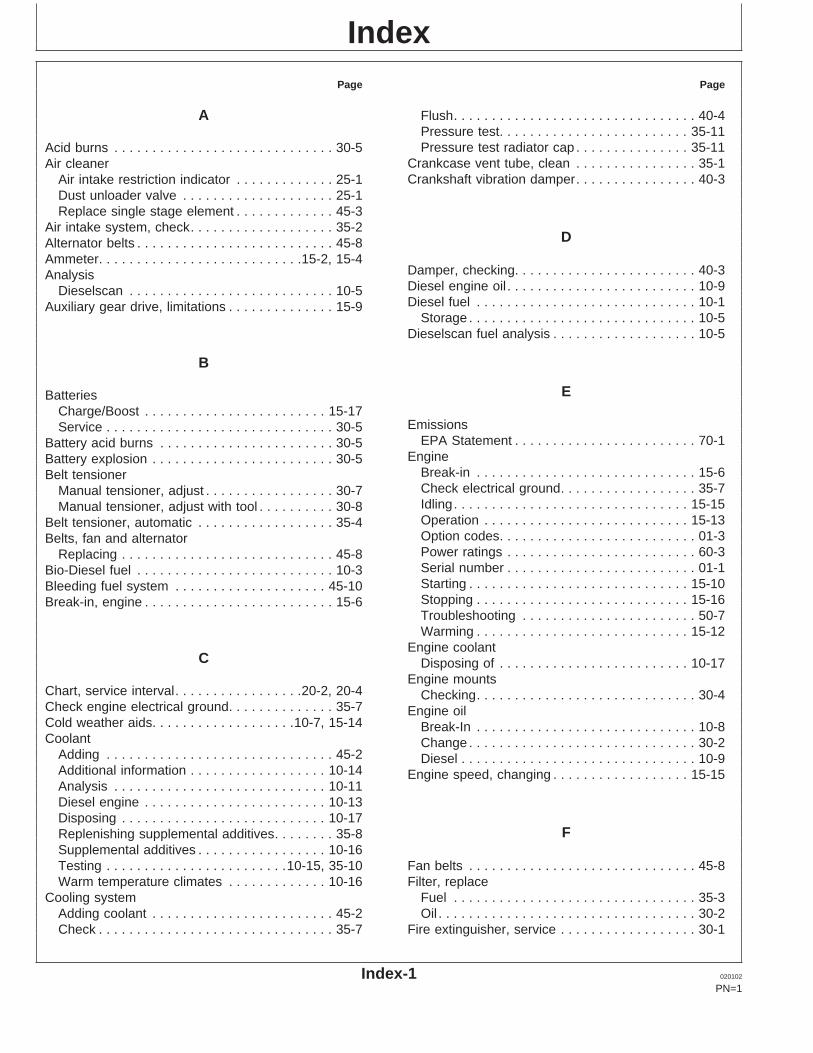
IndexPage Page
A Flush. . . . . . . . . . . . . . . . . . . . . . . . . . . . . . . . 40-4Pressure test. . . . . . . . . . . . . . . . . . . . . . . . . 35-11Pressure test radiator cap . . . . . . . . . . . . . . . 35-11Acid burns . . . . . . . . . . . . . . . . . . . . . . . . . . . . . 30-5
Crankcase vent tube, clean . . . . . . . . . . . . . . . . 35-1Air cleanerCrankshaft vibration damper. . . . . . . . . . . . . . . . 40-3Air intake restriction indicator . . . . . . . . . . . . . 25-1
Dust unloader valve . . . . . . . . . . . . . . . . . . . . 25-1Replace single stage element . . . . . . . . . . . . . 45-3
Air intake system, check. . . . . . . . . . . . . . . . . . . 35-2DAlternator belts . . . . . . . . . . . . . . . . . . . . . . . . . . 45-8
Ammeter. . . . . . . . . . . . . . . . . . . . . . . . . . .15-2, 15-4Damper, checking. . . . . . . . . . . . . . . . . . . . . . . . 40-3AnalysisDiesel engine oil . . . . . . . . . . . . . . . . . . . . . . . . . 10-9Dieselscan . . . . . . . . . . . . . . . . . . . . . . . . . . . 10-5Diesel fuel . . . . . . . . . . . . . . . . . . . . . . . . . . . . . 10-1Auxiliary gear drive, limitations . . . . . . . . . . . . . . 15-9
Storage . . . . . . . . . . . . . . . . . . . . . . . . . . . . . . 10-5Dieselscan fuel analysis . . . . . . . . . . . . . . . . . . . 10-5
B
EBatteriesCharge/Boost . . . . . . . . . . . . . . . . . . . . . . . . 15-17
EmissionsService . . . . . . . . . . . . . . . . . . . . . . . . . . . . . . 30-5EPA Statement . . . . . . . . . . . . . . . . . . . . . . . . 70-1Battery acid burns . . . . . . . . . . . . . . . . . . . . . . . 30-5
EngineBattery explosion . . . . . . . . . . . . . . . . . . . . . . . . 30-5Break-in . . . . . . . . . . . . . . . . . . . . . . . . . . . . . 15-6Belt tensionerCheck electrical ground. . . . . . . . . . . . . . . . . . 35-7Manual tensioner, adjust . . . . . . . . . . . . . . . . . 30-7Idling. . . . . . . . . . . . . . . . . . . . . . . . . . . . . . . 15-15Manual tensioner, adjust with tool . . . . . . . . . . 30-8Operation . . . . . . . . . . . . . . . . . . . . . . . . . . . 15-13Belt tensioner, automatic . . . . . . . . . . . . . . . . . . 35-4Option codes. . . . . . . . . . . . . . . . . . . . . . . . . . 01-3Belts, fan and alternatorPower ratings . . . . . . . . . . . . . . . . . . . . . . . . . 60-3Replacing . . . . . . . . . . . . . . . . . . . . . . . . . . . . 45-8Serial number . . . . . . . . . . . . . . . . . . . . . . . . . 01-1Bio-Diesel fuel . . . . . . . . . . . . . . . . . . . . . . . . . . 10-3Starting . . . . . . . . . . . . . . . . . . . . . . . . . . . . . 15-10Bleeding fuel system . . . . . . . . . . . . . . . . . . . . 45-10Stopping . . . . . . . . . . . . . . . . . . . . . . . . . . . . 15-16Break-in, engine . . . . . . . . . . . . . . . . . . . . . . . . . 15-6Troubleshooting . . . . . . . . . . . . . . . . . . . . . . . 50-7Warming . . . . . . . . . . . . . . . . . . . . . . . . . . . . 15-12
Engine coolantC Disposing of . . . . . . . . . . . . . . . . . . . . . . . . . 10-17
Engine mountsChart, service interval. . . . . . . . . . . . . . . . .20-2, 20-4 Checking. . . . . . . . . . . . . . . . . . . . . . . . . . . . . 30-4Check engine electrical ground. . . . . . . . . . . . . . 35-7 Engine oilCold weather aids. . . . . . . . . . . . . . . . . . .10-7, 15-14 Break-In . . . . . . . . . . . . . . . . . . . . . . . . . . . . . 10-8Coolant Change . . . . . . . . . . . . . . . . . . . . . . . . . . . . . . 30-2
Adding . . . . . . . . . . . . . . . . . . . . . . . . . . . . . . 45-2 Diesel . . . . . . . . . . . . . . . . . . . . . . . . . . . . . . . 10-9Additional information . . . . . . . . . . . . . . . . . . 10-14 Engine speed, changing . . . . . . . . . . . . . . . . . . 15-15Analysis . . . . . . . . . . . . . . . . . . . . . . . . . . . . 10-11Diesel engine . . . . . . . . . . . . . . . . . . . . . . . . 10-13Disposing . . . . . . . . . . . . . . . . . . . . . . . . . . . 10-17
FReplenishing supplemental additives. . . . . . . . 35-8Supplemental additives . . . . . . . . . . . . . . . . . 10-16Testing . . . . . . . . . . . . . . . . . . . . . . . .10-15, 35-10 Fan belts . . . . . . . . . . . . . . . . . . . . . . . . . . . . . . 45-8
Filter, replaceWarm temperature climates . . . . . . . . . . . . . 10-16Cooling system Fuel . . . . . . . . . . . . . . . . . . . . . . . . . . . . . . . . 35-3
Oil . . . . . . . . . . . . . . . . . . . . . . . . . . . . . . . . . . 30-2Adding coolant . . . . . . . . . . . . . . . . . . . . . . . . 45-2Check . . . . . . . . . . . . . . . . . . . . . . . . . . . . . . . 35-7 Fire extinguisher, service . . . . . . . . . . . . . . . . . . 30-1
Index-1 020102
PN=1
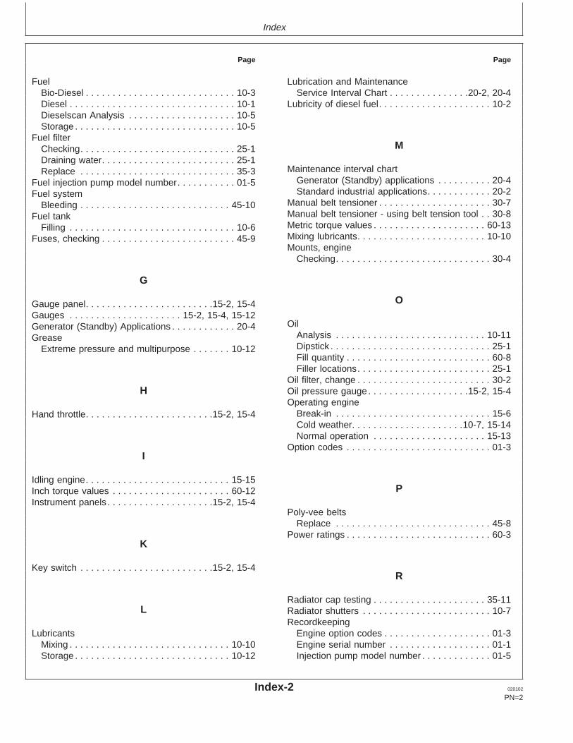
Index
Page Page
Fuel Lubrication and MaintenanceService Interval Chart . . . . . . . . . . . . . . .20-2, 20-4Bio-Diesel . . . . . . . . . . . . . . . . . . . . . . . . . . . . 10-3
Diesel . . . . . . . . . . . . . . . . . . . . . . . . . . . . . . . 10-1 Lubricity of diesel fuel. . . . . . . . . . . . . . . . . . . . . 10-2Dieselscan Analysis . . . . . . . . . . . . . . . . . . . . 10-5Storage . . . . . . . . . . . . . . . . . . . . . . . . . . . . . . 10-5
Fuel filterMChecking. . . . . . . . . . . . . . . . . . . . . . . . . . . . . 25-1
Draining water. . . . . . . . . . . . . . . . . . . . . . . . . 25-1Maintenance interval chartReplace . . . . . . . . . . . . . . . . . . . . . . . . . . . . . 35-3
Generator (Standby) applications . . . . . . . . . . 20-4Fuel injection pump model number. . . . . . . . . . . 01-5Standard industrial applications. . . . . . . . . . . . 20-2Fuel system
Manual belt tensioner . . . . . . . . . . . . . . . . . . . . . 30-7Bleeding . . . . . . . . . . . . . . . . . . . . . . . . . . . . 45-10Manual belt tensioner - using belt tension tool . . 30-8Fuel tankMetric torque values . . . . . . . . . . . . . . . . . . . . . 60-13Filling . . . . . . . . . . . . . . . . . . . . . . . . . . . . . . . 10-6Mixing lubricants. . . . . . . . . . . . . . . . . . . . . . . . 10-10Fuses, checking . . . . . . . . . . . . . . . . . . . . . . . . . 45-9Mounts, engine
Checking. . . . . . . . . . . . . . . . . . . . . . . . . . . . . 30-4
G
OGauge panel. . . . . . . . . . . . . . . . . . . . . . . .15-2, 15-4Gauges . . . . . . . . . . . . . . . . . . . . . 15-2, 15-4, 15-12
OilGenerator (Standby) Applications . . . . . . . . . . . . 20-4Analysis . . . . . . . . . . . . . . . . . . . . . . . . . . . . 10-11GreaseDipstick . . . . . . . . . . . . . . . . . . . . . . . . . . . . . . 25-1Extreme pressure and multipurpose . . . . . . . 10-12Fill quantity . . . . . . . . . . . . . . . . . . . . . . . . . . . 60-8Filler locations. . . . . . . . . . . . . . . . . . . . . . . . . 25-1
Oil filter, change . . . . . . . . . . . . . . . . . . . . . . . . . 30-2H Oil pressure gauge . . . . . . . . . . . . . . . . . . .15-2, 15-4
Operating engineBreak-in . . . . . . . . . . . . . . . . . . . . . . . . . . . . . 15-6Hand throttle. . . . . . . . . . . . . . . . . . . . . . . .15-2, 15-4Cold weather. . . . . . . . . . . . . . . . . . . . .10-7, 15-14Normal operation . . . . . . . . . . . . . . . . . . . . . 15-13
Option codes . . . . . . . . . . . . . . . . . . . . . . . . . . . 01-3I
Idling engine. . . . . . . . . . . . . . . . . . . . . . . . . . . 15-15PInch torque values . . . . . . . . . . . . . . . . . . . . . . 60-12
Instrument panels . . . . . . . . . . . . . . . . . . . .15-2, 15-4Poly-vee belts
Replace . . . . . . . . . . . . . . . . . . . . . . . . . . . . . 45-8Power ratings . . . . . . . . . . . . . . . . . . . . . . . . . . . 60-3
K
Key switch . . . . . . . . . . . . . . . . . . . . . . . . .15-2, 15-4R
Radiator cap testing . . . . . . . . . . . . . . . . . . . . . 35-11L Radiator shutters . . . . . . . . . . . . . . . . . . . . . . . . 10-7
RecordkeepingEngine option codes . . . . . . . . . . . . . . . . . . . . 01-3Lubricants
Mixing . . . . . . . . . . . . . . . . . . . . . . . . . . . . . . 10-10 Engine serial number . . . . . . . . . . . . . . . . . . . 01-1Injection pump model number . . . . . . . . . . . . . 01-5Storage . . . . . . . . . . . . . . . . . . . . . . . . . . . . . 10-12
Index-2 020102
PN=2
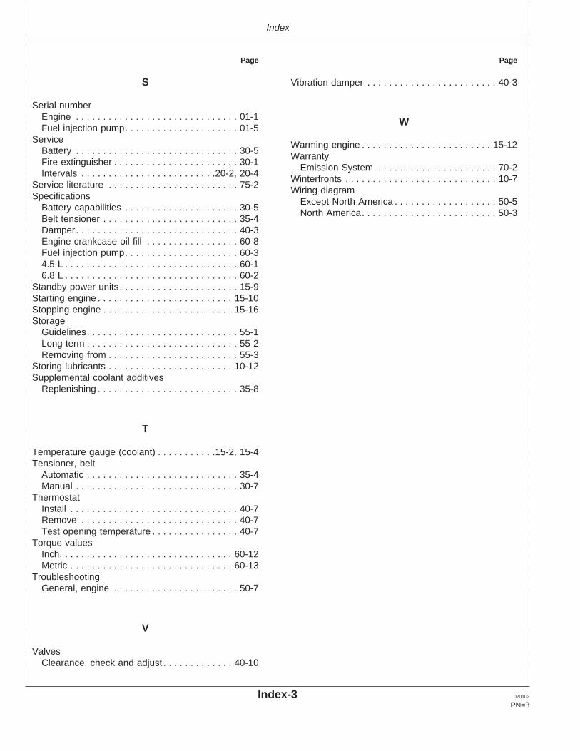
Index
Page Page
S Vibration damper . . . . . . . . . . . . . . . . . . . . . . . . 40-3
Serial numberEngine . . . . . . . . . . . . . . . . . . . . . . . . . . . . . . 01-1 WFuel injection pump. . . . . . . . . . . . . . . . . . . . . 01-5
ServiceWarming engine . . . . . . . . . . . . . . . . . . . . . . . . 15-12
Battery . . . . . . . . . . . . . . . . . . . . . . . . . . . . . . 30-5Warranty
Fire extinguisher . . . . . . . . . . . . . . . . . . . . . . . 30-1Emission System . . . . . . . . . . . . . . . . . . . . . . 70-2
Intervals . . . . . . . . . . . . . . . . . . . . . . . . .20-2, 20-4Winterfronts . . . . . . . . . . . . . . . . . . . . . . . . . . . . 10-7
Service literature . . . . . . . . . . . . . . . . . . . . . . . . 75-2Wiring diagram
SpecificationsExcept North America . . . . . . . . . . . . . . . . . . . 50-5
Battery capabilities . . . . . . . . . . . . . . . . . . . . . 30-5North America. . . . . . . . . . . . . . . . . . . . . . . . . 50-3
Belt tensioner . . . . . . . . . . . . . . . . . . . . . . . . . 35-4Damper. . . . . . . . . . . . . . . . . . . . . . . . . . . . . . 40-3Engine crankcase oil fill . . . . . . . . . . . . . . . . . 60-8Fuel injection pump. . . . . . . . . . . . . . . . . . . . . 60-34.5 L . . . . . . . . . . . . . . . . . . . . . . . . . . . . . . . . 60-16.8 L . . . . . . . . . . . . . . . . . . . . . . . . . . . . . . . . 60-2
Standby power units . . . . . . . . . . . . . . . . . . . . . . 15-9Starting engine . . . . . . . . . . . . . . . . . . . . . . . . . 15-10Stopping engine . . . . . . . . . . . . . . . . . . . . . . . . 15-16Storage
Guidelines. . . . . . . . . . . . . . . . . . . . . . . . . . . . 55-1Long term . . . . . . . . . . . . . . . . . . . . . . . . . . . . 55-2Removing from . . . . . . . . . . . . . . . . . . . . . . . . 55-3
Storing lubricants . . . . . . . . . . . . . . . . . . . . . . . 10-12Supplemental coolant additives
Replenishing . . . . . . . . . . . . . . . . . . . . . . . . . . 35-8
T
Temperature gauge (coolant) . . . . . . . . . . .15-2, 15-4Tensioner, belt
Automatic . . . . . . . . . . . . . . . . . . . . . . . . . . . . 35-4Manual . . . . . . . . . . . . . . . . . . . . . . . . . . . . . . 30-7
ThermostatInstall . . . . . . . . . . . . . . . . . . . . . . . . . . . . . . . 40-7Remove . . . . . . . . . . . . . . . . . . . . . . . . . . . . . 40-7Test opening temperature . . . . . . . . . . . . . . . . 40-7
Torque valuesInch. . . . . . . . . . . . . . . . . . . . . . . . . . . . . . . . 60-12Metric . . . . . . . . . . . . . . . . . . . . . . . . . . . . . . 60-13
TroubleshootingGeneral, engine . . . . . . . . . . . . . . . . . . . . . . . 50-7
V
ValvesClearance, check and adjust . . . . . . . . . . . . . 40-10
Index-3 020102
PN=3

Index
Index-4 020102
PN=4

Gary A Reinholtz
TP-5853 2/02