4+ OTT (3 % 4$$ Karthick V. Gourishankar 6!!!. …/67531/metadc623117/...Karthick V. Gourishankar...
20
. . .- ,—.4 c?” . Electrometallurgical Treatment of Oxide Spent Fuel — Engineering-Scale Development Eric J. Karen Argonne National Laboratory Chemical Technology Division . 9700 South Cass Avenue Argonne, IL 60439 4 + c J&) OTT (3 % 4$$ 6!!! 4$$ Karthick V. Gourishankar . Argonne National Laboratory 0 Chemical Technology Division 9700 South Cass Avenue Argonne, IL 60439 . The subm~~edmanuscript has been created by the Universi~ of Chicago as Operator of Argonne National Laboratory (“Argonne”) under Contract No. W-31-109-ENG-38 with the U.S. Department of Energy. The U.S. Government retains for itself, and others act- ing on its behalf, a paid-up, nonexclusive, irrevocable worldwide license in said arlicle to reproduce, prepare derivative works, dis- tribute copies to the public, and perform pub- licly and display publicly, by or on behalf of the Government. Submitted for Publication in - Proceedings of the American Nuclear Society Third Topical Meeting on DOE Spent Nuclear Fuel and Fissile Materials Management, Charleston, SC (1998) .— ---- . .-
Transcript of 4+ OTT (3 % 4$$ Karthick V. Gourishankar 6!!!. …/67531/metadc623117/...Karthick V. Gourishankar...

. .
.-,—.4
c?”
.
Electrometallurgical Treatment of Oxide Spent Fuel — Engineering-Scale Development
Eric J. Karen
Argonne National Laboratory
Chemical Technology Division
. 9700 South Cass Avenue
Argonne, IL 60439
4+cJ&) OTT
(3 % 4$$6!!! 4$$Karthick V. Gourishankar .
Argonne National Laboratory 0
Chemical Technology Division
9700 South Cass Avenue
Argonne, IL 60439
.The subm~~edmanuscript has been createdby the Universi~ of Chicago as Operator ofArgonne National Laboratory (“Argonne”)under Contract No. W-31-109-ENG-38 withthe U.S. Department of Energy. The U.S.Government retains for itself, and others act-ing on its behalf, a paid-up, nonexclusive,irrevocable worldwide license in said arlicleto reproduce, prepare derivative works, dis-tribute copies to the public, and perform pub-licly and display publicly, by or on behalf ofthe Government.
Submitted for Publication in
- Proceedings of the American Nuclear Society
Third Topical Meeting on DOE Spent Nuclear Fuel
and Fissile Materials Management,
Charleston, SC (1998)
.— ---- . .-

DISCLAIMER
This report was prepared as an account of work sponsoredby an agency of the United States Government. Neither theUnited States Government nor any agency thereof, nor anyof their employees, make any warranty, express or implied,or assumes any legal liability or responsibility for theaccuracy, completeness, or usefulness of any information,apparatus, product, or process disclosed, or represents that “its use would not infringe privately owned rights. Referenceherein to any specific commercial product, process, orservice by trade name, trademark, manufacturer, orotherwise does not necessarily constitute or imply itsendorsement, recommendation, or favoring by the UnitedStates Government or any agency thereof. The views andopinions of authors expressed herein do not necessarilystate or reflect those of the United States Government orany agency thereof.

I
DISCLAIMER
Portions of this document may be illegiblein electronic image products. Images areproduced from the best available originaldocument.
I
I

. .
., Abstract
I
Argonne National Laboratory (ANL) has developed the electrometallurgical
treatment process for conditioning various Department of Energy (DOE) spent fuel types
for long-term storage or disposal. This process uses electrorefting to separate the
constituents of spent fuel into three product streams: metallic uranium, a metal waste form
containing the cladding and noble metal fission products, and a ceramic waste form
containing the transuranics, and rare earth, alkali, and akdine earth fission products.
While metallic fuels can be directly introduced into the electrorefiner, the actinide
components of oxide fuels must first be reduced to the metallic form. The Chemical
Technology Division of AFT has developed a process to reduce the actinide oxides that
uses lithium at 650”C in the presence of molten LiCl, yielding the actinide metals and LizO.
A significant amount of work has already been accomplished to investigate the basic
chemistry of the lithium reduction process and to demonstrate its applicability to the
treatment of light-water reactor- (LWR-) type spent fuel. The success of this work has led
to conceptual plans to construct a pilot-scale oxide reduction facility at ANL’s Idaho site. In
support of the design effort, a series of laboratory- and engineering-scale experiments is
being conducted using simulated fuel. These experiments have focused on the engineering
issues associated with scaling-up the process and proving compatibility between the
reduction and electrorefining steps. Specific areas of investigation included reduction
reaction kinetics, evaluation of various fuel basket designs, and issues related to
electrorefining the reduced product. - This paper summarizes the results of these
experiments and outlines plans for future work.
2..
..——.— ..—, . I

. .
I. INTRODUCTION
The Department of Energy (DOE) inventory of spent nuclear fuel contains a wide
variety of fiel types that are unsuitable for direct repository disposal in their current form.
Concerns about the enrichment, chemical stability, and physical condition of these fuel
types complicate the task of preparing and qualif@g them for repository disposal. The
electrometallurgical (EM) treatment technique developed by Argome National Laboratory
(ANL) has the potential to simpli@ preparing and qualifying these fuels for disposal by
converting them into a uniform set of three product streams: uranium metal, a metal waste
form, and a ceramic waste form. The separation of the constituents of spent fiel into these
product streams is accomplished by electrorefining the spent fuel.
A demonstration of the EM process is currently underway using sodium-bonded
metallic fhel from EBR-11,the fuel type for which the process
time, the Chemical Technology Division (CMT) of ANL is
process can also be used to treat non-metallic DOE fuel types.
process requires a metaUic feed, non-metallic fbels must first
was designed. 1 At the same
evaluating whether the EM
Because the electroreftig
undergo a head-end step to
convert the actinide components into metals state before electrorefining. For oxide fuels,
CMT has developed a process to reduce the actinide oxides that uses lithium at 650”C in the
presence of molten LiCl, yielding the metallic actinides and LizO. The LizO, which is
soluble in LiCl, is then electrolytically decomposed to lower its concentration in the
reduction salt before the salt is recycled to the reduction vessel. The lithium metal,
recovered from the reduction salt, is also recycled to the reduction vessel for subsequent
reductions.
A significant amount of work has already been accomplished to investigate the basic
chemistry of the lithium reduction process and to demonstrate its applicability to the
treatment of light-water reactor- (LWR-) type spent fuel.z The success of this work has led
to conceptual plans to construct a pilot-scale oxide reduction (PSOR) facili~ at A.FW’s
3
.— ,—. . ,—.. . . .. . . . ____

..
Idaho sites Insupport of thedesign effort, asefies of laboratory and engineering-scale
experiments is being conducted using simulated fuel. These experiments have focused on
the engineering issues associated with scaling-up the process and proving that the reduction
and electrorefining steps are compatible. Specific areas of investigation included reduction
reaction kinetics, evaluation of various fuel basket designs,
electrorefting the reduced product. This paper summarizes
experiments and outlines plans for future work.
and issues related to
the results of these
II. PROCESS DESCRIPTION
Figure 1 is a simplified flowsheet that illustrates the different portions of the lithium
reduction process and its interfaces with other steps in the electrometalhrgica! treatment
technique. Fuel elements are chopped into segments, and the resultant mixture of oxide fiel
and cladding is loaded into a fuel basket. The fuel basket is then transferred to the reduction
vessel, where it is reduced with lithium dissolved in molten LiCl at 650”C. Molten lithium
in contact with the salt maintains the lithium activity at unity. The actinide oxides are
reduced, and the actinide metals and LbO are formed. The Li20, which is soluble in LiCl,
is then electrolytically decomposed at 650”C in a salt-recovery step. The resulting salt,
which is low in Li,O concentration, and the lithium metal are recycled to the reduction
vessel for subsequent fuel reductions. The fuel basket from the reduction vessel, which
contains the reduced product including uranium, transuranics, and cladding hulls, is
transferred for electrorefining. The electrorefiner is operated at 500”C and uses LiC1-KCl
eutectic salt, with dissolved UCl~ as the electrolyte. The electrorefting process then
separates the constituents of spent fuel into three product streams: metallic uranium, a metal
waste form, and a ceramic waste form.
III. EXPERIMENTAL
4
. .. —.. —— ..-— . . ------- % -- .—-,--=. .— .,, , ~—— . .. .. I

.
A. Laboratory-Scale Equipment
The laboratory-scale equipment at CMT was built to support testing
chemistry and scale-up issues related to the lithium reduction process.
laboratory-scale experiments were performed in a high-purity helium (%O
atmosphere glovebox. The reduction experiments were performed in 6-in. -
of process
All the
< 5 ppm)
(15.2-cm-)
diam. furnace wells. The primary crucible used in these
stainless steel, with a volume of 600 cc. A stainless steel
experiments. The mass of fuel used in these experiments
experiments was made of 304
stirrer was used in some of the
varied from 20 to 200 g. Fuel
baskets were built of stainless steel screening to hold the fuel in the reduction vessel.
B. Engineering-Scale Equipment
The engineering-scale facility at CMT was designed to support testing of all of the
process steps at fuel loadings of up to 20 kilograms per batch. The facility consists of three
major components: the reduction vessel, the electrochemical vessel, and a casting station.
All were enclosed in a large (7.6 m x 2.4 m x 2.6 m) argon atmosphere glovebox. The
reduction vessel holds the salt, fuel, and lithium during the reduction step. The
electrochemical vessel holds the molten salt during the salt recovery step and can be
configured for electrorefining the reduced product. Each vessel is approximately 1.2 m tall
and 1 m in diameter and contains a crucible that holds the molten salt. The inner crucibles
are 0.4 m in diameter and 0.7 m tall. A casting station is provided to allow the salt to be
cast into ingots for storage between process steps. The facility is qualified to handle limited
quantities of plutonium and other transuranics. Figure 2 shows a cut-away view of the
reduction vessel as configured for the engineering-scale experiments described here.
C. Simulated Fuel
5 I
-??-—.---.,— --,m= , ..-—., .- .-r. . . ,.. ,e — —. —-

.
The fuel material used in these experiments was selected to simulate that which
might result from chopping spent oxide fuel assemblies into segments. The. size of these
fuel segments is an important design paramete~ The largest particle size determines the
minimum time for the reduction to be completed, while the smallest presents containment
problems. Studies performed at Oak Ridge National Laboratory (ORNL) on shearing fhel
bundles provided a basis for selecting
tests.’ The ORNL studies estimated
segments would dislodge 50% of the
the size distribution of the material used in these’
that shearing a fuel bundle into l-in. (2.54-cm)
UOZ from the cladding. For testing the lithium
reduction process, we conservatively assumed that the material not dislodged remained as
an intact fragment. Unirradiated stainless steel-clad fuel rods, 0.95 cm O.D., were cut into
l-cm-long segments to represent the maximum expected pru-title size if fuel assemblies
were sheared into 1-in. (2.54-cm) segments.
The ORNL work also examined the particle size distribution of material dislodged
from chopping single UOZ rods into 0.5-in. (1.27-cm) segments. The dislodged
fragments were all smaller than 2000 pm. Half of the particles (by mass) were larger than
100 pm (corresponding to a 170 mesh screen). Five percent of the particles were less than
1 pm. For testing the lithium reduction process, matetial obtained from crushing
unirradiated U09 pellets was used to represent fuel dislodged from the cladding during the
chopping operation. The individual pieces of crushed U02 ranged in size from several
millimeters down to-45 microns. Smaller particles were not used because the equipment to
contain them in the reduction system has not yet been filly developed.
Note that the ORNL work was done using unirradiated fuel and simulated fuel
bundles. Because of the nature of irradiated fuel, ‘it will probably be more easily
fragmented than unirradiated U02. Thus, the simulated fuel used in these experiments is
considered to be a conservative representation of actual spent fhel for estimating reduction
kinetics.
6
—- .—., .. . . .../, ... . .-,. ,. ...”, .. . . ... . ... . . . ,.

.,
D. Analytical Methods
The primary analytical tools used to monitor the
included visual inspection, optical metallography, chemical
(XRD). Chemical titrations were performed with O.1~
extent and rate of reduction
titration, and x-ray diffraction
HC1 to determine the L~O
concentration of salt samples periodically drawn fi-om the reduction salt. This method was
very useful in monitoring the rate of reduction. At the end of the reduction, samples of the
reduction product we;e ground, loaded into glass capillaries, and then analyzed by XI/D
for phase information. In laboratory-scale pellet reductions, reduced pellets were
sectioned, metallographically prepared, and examined with an optical microscope.
IV. EXPERIMENTAL RESULTS
A. Laboratory-Scale Experiments
In preparation for the engineering-scale experiments, a series of laboratory-scale
experiments was performed to identify the factors affecting reaction kinetics. Specifically,
the experiments focused on the relationship between the reduction rate and the stirring
speed, fuel morphology, and the basket dimensions. These exper.irnents were intended to
predict the required reduction times in the engineering-scale experiments.
Experiments were run in which crushed U02 and clad UOZ fuel rod sections were
reduced with and without stirring. In these experiments, the fuel was held in a 1.5 cm x 1.5
cm x 5-cm-tall basket. Lithium-saturated stainless steel foam was the source of lithium.
This method was chosen because the iithium recovered in the salt-recovery step is
contained in a stainless steel foam cathode. The results of these experiments suggest that
complete reduction of the crushed U02 could be accomplished in as little as 12 hours, with
adequate stirring. Stirring had little effect on the reduction rate of clad UOZpellets: They
required 36 hours to be completely reduced. The difference in the effect of stirring on the
7
~.. .Z...——. R.. ..

..
crushed UOZand on the clad pellets is thought to result from differences in the relationship
between particle size and basket dimensions. Stirring increases the rate of crushed. U02
reduction because it increases contact between the bulk salt (containing dissolved lithium)
and the fuel particles. Without stirring, the bed of crushed U02 tends to act like a single
pellet whose length is related to the basket thickness. The results of these experiments are
plotted in Figure 3.
B. Engineering-Scale Experiments
Two engineering-scale experiments, designated ES-5 and ES-6, are discussed in
this paper. They were essentially identical, except for the design of the fuel basket used to
hold the UOZ. The primary purpose of ES-5 was to test whether the reduction rates
obtained at laboratory-scale could be achieved at engineering-scale. Because the thickness
of the fuel basket is a critical parameter in determining reduction rate, the geometry of the
fuel basket used in ES-5 was specifically designed to resemble the one used in the
laboratory-scale work. The primary purpose of ES-6 was to evaluate the suitability of using
an existing electrorefiner basketl (the Mk V) for the reduction step. The Mk-V basket is
considerably thicker than the fuel basket tested in ES-5 and thus required an independent
test. Additional objectives in both ES-5 and ES-6 were checking whether lithium contained
on prototypical cathodes can be used for reductions, evaluating bulk salt sample titration as
a means of monitoring reaction progress, and characterizing the reduction product.
The feed material for ES-5 comprised 5.2 kg of crushed UOZ and 77 kg of salt.
After crushing, the particles were sieved and a particle size distribution ‘was obtained
consisting of four size fractions: 45-590 ~m, 590-1190 pm, 1190-2830 pm, and >2830
pm.. The crushed U02 was loaded into the fuel basket such that the different particle sizes
‘ One of the design criteria for the PSOR facility is that it be compatible with the Mk-V electrorefiner.This requires that the oxide fuel be reduced in the Mk-V basket assembly, which is then transferred to theelectrorefiner.
8
-y ~.. —. ----- —. .,,. .- -T -.——— .. .. .

. .
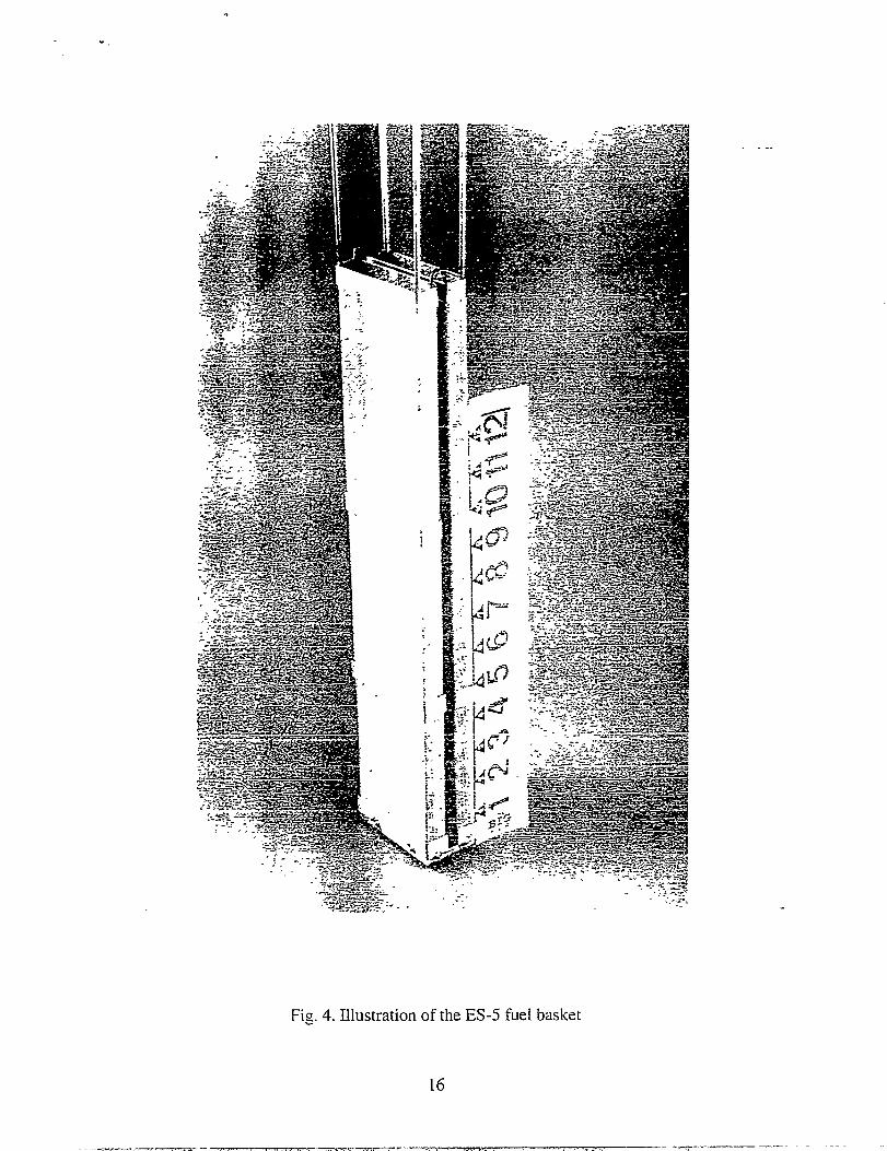
occupied separate layers in the fuel basket. The fuel basket itself consisted of two separate
compartments bolted to a single steel plate at the bottom. The compartments were separated
by a l-cm gap to allow free access of salt to all faces of the fuel basket. The compartments
were made of a thick gauge (10 mesh) stainless steel screening with a 325 mesh stainless
steel screen lining on the inside. Each basket compartment was 1.5 cm thick, 3.5 in. (8.9
cm) wide, and 15 in. (38.1 cm) long. A photograph of the basket is provided in Figure 4.
Lithium was contained in a cylindrical porous metal matrix, prototypical of the cathode
used to collect lithium in the salt recovery step. The progress of the reduction was
measured by periodically taking salt samples and titrating them to determine the L~O
concentration.
The results of ES-5 were very encouraging. Based on the LizO concentration in the
salt samples, the reduction rate was similar to that obtained in laboratory-scale experiments.
The reduction was essentially complete in 12-20 hours; there was no significant increase in
the Li,O concentration after 20 hours. This reduction is the fastest to date in the
‘engineering-scale system. Figure 5 illustrates the extent of reduction as a function of time.
The reduced product showed no evidence of unreduced UOZ, either by visual examination
or by XRD.
The mass of entrained/occluded salt in the reduction product as a function of the
fuel particle size was also determined. The dissolved LbO in the entrained/occluded salt
reacts with the UCl~ in the electrorefmer to form UOZ, requiring that the UClq be
replenished periodically. Thus, it is important to estimate the salt carryover from the
reduction step to the electrorefiner. The mass of entrained/occluded salt was found to
increase with decreasing particle size of the fuel. The coarsest fuel fraction contained 1.4
wt% salt, while the finest fuel fraction contained as much as 12 wt% salt. The average
entrained/occluded salt in the fuel basket was estimated to be 11 wt%. --
9
..-...- .-.-mrrm ----.-, -=. . . .. -. . ...... . .. .. ...... ,. -,. .. . .. . . . .. . . .... -’. —.

The ES-6 reduction was performed in a Mk V basket. The Mk V basket consists of
a perforated sheet metal shell with a single insert made of 325- mesh stainless steel -
screening. The insert was about 2.7 cm thick. Figure 6 is an illustration of the outer shell
and the insert in a Mk V basket. Thus, the Mk V basket is distinctly different in two aspects
from the ES-5 basket: (1) it is about twice as thick and (2) its exterior is made of perforated
sheet metal instead of 10 mesh screening. While the basket thickness is likely to affect the
reduction kinetics, the second factor may affect the extent of salt access in the basket area.
The feed material for ES-6 was 3.7 kg of crushed U02 The reduced loading as compared
to ES-5 results from the smaller volume of the Mk V basket. The fuel was separated into
the same four size fractions as in ES-5. The loading of the fuel basket was arranged so that
the finest fuel fraction lay at the bottom and the coarsest fuel fraction was at the top of the
fuel basket. The basket was loaded with the crushed fuel to a height of 12.5 in. (31.8 cm).
A few l-cm clad fuel rod sections were also included in the fuel basket. The same salt that
was used in ES-5 was used here.
The reduction rate in ES-6 was significantly slower than that measured in ES-5; the
two reduction rates are compared in Figure 5. The ES-6 reduction was stopped afler about
78 hours when it was apparent that the reduction was essentially complete. A clad pellet
removed from the fuel basket after 72 hours was sectioned and found to be completely
reduced. Visual examination of the reduced product at the end of the reduction showed no
evidence of unreduced UOZ. The XRD results are pending. The two remaining clad pellets
in the fuel basket were sectioned at the end of the run; visual examination showed that they
too were completely reduced. The cross sections of these reduced pellets had the same
characteristic appearance as those of the completely reduced clad pellets in earlier
laboratory-scale experiments. It was not clear from the measured titration data when the
reduction was complete because of the scatter in the data. The bulk of the reduction
appears to have been completed in about 50-60 hours. The salt entrainment in the reduction
10
.-——-,---T” .,87, , - .,”: ,, , ..-, .. . ~.,. .. o,. 1., ~,.. .- ....,~..,

. .
product was not measured as a function of the fuel particle size in ES-6, but the average
entrained/occluded salt in the fuel basket was estimated to be 13 wt%.
V. CONCLUSIONS
The experiments described in this paper confined that the large-scale reduction of
oxide fuel is feasible using equipment compatible with the major interfacing processes: fuel
element chopping, salt recovery and electrorefting. The fundamental parameters
controlling the reduction rate have been identified and successfully modeled at the
laboratory-scale. Based on the characteristics of the reduced uranium product (i.e., salt
carryover and extent of reduction), it appears that the lithium reduction process can provide
a suitable feed material for the electrorefiner.
Laboratory-scale work identified the effect of basket design, stirring, and fiel
morphology on the reduction kinetics. Use of lithium-ffled cathodes as the lithium source
in the reduction step has been demonstrated as a viable option. This ensures compatibility
between the reduction and the salt recovery step and will enable Iithium-ftied cathodes
from the salt recovery step to be used directly as a lithium source in the reduction step.
Chemical titration of salt samples was found to be a very useful analytical technique
to monitor the rate and extent of reduction. However, a significant degree of scatter was
observed in the measured data, especially in the engineering-scale reduction ES-6. These
results suggest that- the sampling procedures and/or the titration methods have to be
improved, An excellent reduction rate was achieved with the fuel basket geometry used in
ES-5. Although reduction was apparently complete with the Mk V basket, its thickness
significantly increased the reduction time required. Thus, it is important to d$termine if the
measured reduction time with the Mk V basket is acceptable. This depends, in part, on the
rate of the other major interfacing processes: salt recove~ and electrorefting.
11
.-rr - - q~.~...~; ..7.—7,— ,+.,, ,,./r ... ,...,...d’ . . ..-—..., . . ... ....,,-7-.W-.. .. ... > >,ZC —

Future work will focus on the development of a suitable containment for fine
particles (<45 pm) and the reduction of the consolidated fines. Reduction of actual spent -
fuel and laboratory- and engineering-scale tests of electrorefining the reduced product are
aksoplanned.
ACKNOWLEDGEMENTS
While the engineering- and laborato~-scale experiments were the result of efforts
of many individuals, we want to acknowledge the contributions of the following people as
having special significance: R. E. Everhart, D. W. Warren, and E. -J.Wesolowski for their
part in building and operating the equipment and D. L. Bowers and C. S. Sabau of the
ANL Analytical Chemistry Laboratory for the analytical work associated with the project.
REFERENCES
1. R. W. Benedict and S. P. Henslee, “The EBR-11 Spent-Fuel Treatment Demonstration
Project,” Trans. Am. Nuc1. Sot. 77,75 (1997).
2. E. J. Karen, R. D. Pierce and T. P. Mulcahey, “Treatment of Oxide Spent Fuel Using
the Lithium Reduction Process;’ Proc. of the American Nuclear Society Embedded Topical
Meeting on DOE Spent Nuclear Fuel and Fissile Material Management, Reno, NV, June
16-20, 1996, pp. 35;-58 (1996).
3. S. D. Herrmam et al., “Pilot-Scale Equipment Development for LM.ium-Based
Reduction of Spent Oxide Fuel,” these proceedings.
4. C. D. Watson et al., “Mechanical Processing of Spent Power Reactor Fuel at Oak Ridge
National Laboratory;’ Proc. of the AEC Symposium for Chemical Processing of Irradiated
Fuels from Power, Test, and Research Reactors, Richland, WA, October 20-21, 1959,
USAEC Report TID-7583, pp. 357-64, (1960).
12
v- ,—. — ------- I

Salt Recovery650”C
I 4Recycled Salt +
Lithium
Fuel
“Q
ReductionChopping/Crushing 650°C
t Reduced Product
w
I Electrorefining500 “c
Fig. 1. Simplified flowsheet of the lithium reduction process and its interfaces with the
other steps in the electrometallurgical treatment technique
13
I- — .—--------- ......-.,-z-!X.mm . . . , , . . . . . ,, .,... ,,- , , , . . . . . . . .,. .
. . . . . .

.-
—
MIXER ‘ASSEMBLY
FUEL BASKET
II L-K-MELT LEVEL
CRUCIBLE WALL
LITHIUMSOURCE
G::3+?
Fig. 2. Cut-away view of the reduction vessel as configured for the latest engineering-scale
experiments
14

.
.,
100
80
60
40
20
0
~ Crushed UOZ,Unstirred
~ Clad U02 Pellets, Unstirred
~ Clad U02 Pellets, Stirred
0 10 20 30 40 50
Time, h
Fig. 3. Effect of stirring on the reduction rate of crushed and clad UOZpellets in
laboratory-scale experiments
15
—. —.... —. .. —. . —
.
.
Fig. 4. Illustration of the ES-5 fuel basket
16
. ..
—. ——. —.— . -- - -= ——.. . .

120
1“’’’’’’’’’’’’’’’’’’’’’’’’’’’’’’’’’’’”{
100
80
60
40
20
0
o 10 20 30 40 50 eo 70 ao
Time, h
Fig. 5. Extent of reduction as a function of time in ES-5 and ES-6 experiments
.-
17
—.. —m-. -.—m..., .>......... .. ,m.m ..-. . ., , ., ,. ..... .. ....... . .,.,... .,-,... _

.
Fig. 6. Illustration of the Mk V outer basket and insert used in ES-6
Is
,-. —- -.—. . . . ... .. . ... .- --rra . .