3D-WLCSP Package Technology Processing and Reliability
14
1 3D-WLCSP Package Technology: Processing and Daniel F. Baldwin, Ph.D., Paul N. Houston, Brian Lewis, Fei Xie, Ph.D., Zhaozhi Li, Ph.D.* Reliability Characterization © ENGENT, Inc. 2012 Daniel F. Baldwin, Ph.D. 1 ENGENT Inc. * Auburn University Outline Packaging Technology Trends 3D Integration and Wafer Level Packaging Bridge 3D Integration and Wafer Level Packaging Bridge 3D Wafer Level Chip Scale Packaging (3D-WLCSP) Yield and Reliability Study Test vehicles for the first and second level assembly First level assembly and reliability Second level assembly © ENGENT, Inc. 2012 Daniel F. Baldwin, Ph.D. Second level reliability and failure analysis Summary and conclusions 2
Transcript of 3D-WLCSP Package Technology Processing and Reliability

1
3D-WLCSP Package Technology: Processing and
Daniel F. Baldwin, Ph.D., Paul N. Houston, Brian Lewis,
Fei Xie, Ph.D., Zhaozhi Li, Ph.D.*
g gy gReliability Characterization
© ENGENT, Inc. 2012 Daniel F. Baldwin, Ph.D.1
ENGENT Inc.
* Auburn University
Outline
Packaging Technology Trends
3D Integration and Wafer Level Packaging Bridge 3D Integration and Wafer Level Packaging Bridge
3D Wafer Level Chip Scale Packaging (3D-WLCSP)
Yield and Reliability Study
Test vehicles for the first and second level assembly
First level assembly and reliability
Second level assembly
© ENGENT, Inc. 2012 Daniel F. Baldwin, Ph.D.
Second level reliability and failure analysis
Summary and conclusions
2
2
Packaging Technology Trends
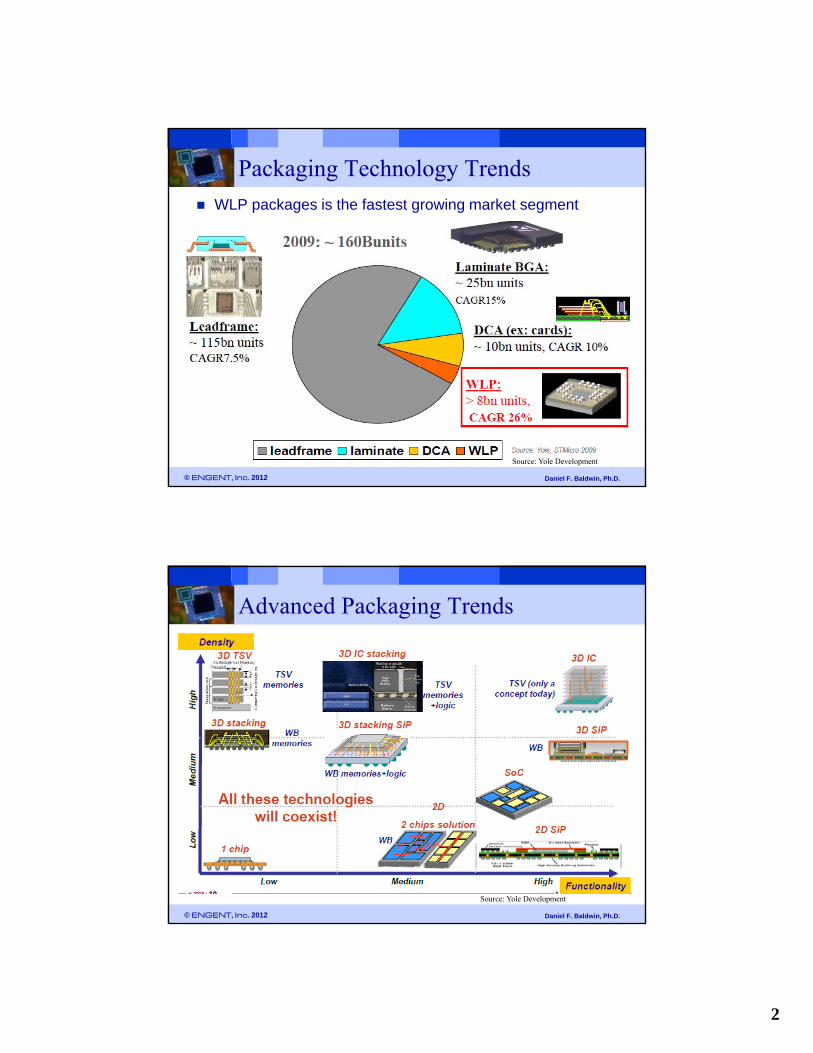
WLP packages is the fastest growing market segment
© ENGENT, Inc. 2012 Daniel F. Baldwin, Ph.D.
Source: Yole Development
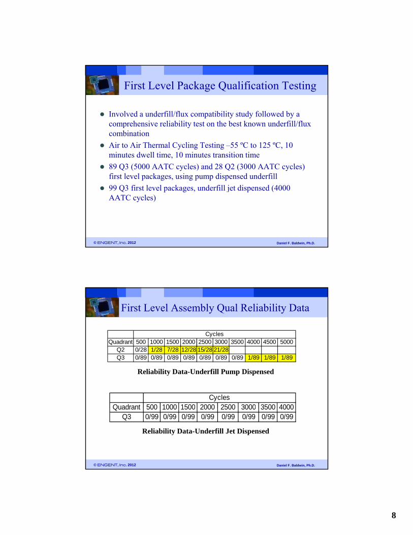
Advanced Packaging Trends
© ENGENT, Inc. 2012 Daniel F. Baldwin, Ph.D.
Source: Yole Development

3
Bridging the 3D-IC Gap Wafer-level-packaging technologies are of multiple flavors and will
bridge the gap between Front-end wafer and BE, assembly & test manufacturing environments
© ENGENT, Inc. 2012 Daniel F. Baldwin, Ph.D.
Source: Yole Development
Overall Advanced Packaging Demand Wafer-level-packages have emerged as the fastest growing
semiconductor packaging technology with more than 27% CAGR in units and 18% in wafers over the next 5 years to come
© ENGENT, Inc. 2012 Daniel F. Baldwin, Ph.D.
Source: Yole Development

4
3D-WLCSP: Die-to-Wafer Integration
Three Dimensional Wafer Level Chip Scale Packaging (3D-WLCSP) technology – leverages the existing infrastructures of high throughput wafer level packaging and low cost flip chiphigh throughput wafer level packaging and low cost flip chipprocess
Singulation
Source: VTI
© ENGENT, Inc. 2012 Daniel F. Baldwin, Ph.D.7
3D-WLCSP: 3D Structure
Two levels of interconnection
1st level interconnection: Flip chip on CSP attachment at the wafer level Silicon on silicon structureS
Face to face bonding through flip chip solder joint
Pb free (Sn-96.5%, Ag-3%, Cu-0.5%) application
Fine pitch (85 μm – 200 μm), thin profile (100 μm FC thickness)
2nd level interconnection: mount of singulated 1st level package to PCB Silicon on PCB (or other carrier)
Standard CSP SMT assembly process
Two levels of underfill application
© ENGENT, Inc. 2012 Daniel F. Baldwin, Ph.D.8
1st Level – Silicon on Silicon 2nd Level – Silicon on Other Carrier

5
Yield and Reliability Study
Yield Improve first level (wafer assembly level) flip chip process yieldp ( y ) p p p y
Study second level CSP Surface Mount process yield Solder paste selection
Reflow process study
Reliability Underfill process evaluation for both first level and second level packages
Flux/underfill compatibility study
© ENGENT, Inc. 2012 Daniel F. Baldwin, Ph.D.
First level reliability & second level reliability qualification
9
Test Vehicles – 1st and 2nd Level WLCSP Assembly
Quadrant 1Quadrant 2 Flip Chip Die
© ENGENT, Inc. 2012 Daniel F. Baldwin, Ph.D.10
Quadrant 3 Quadrant 4
WLCSP Substrate Wafer
2x2 WLCSP Tile

6
Quadrant 1 Quadrant 2
PA
Test Vehicles – 1st and 2nd Level WLCSP Assembly
Flip ChipSite
WLCSPSolder Balls
© ENGENT, Inc. 2012 Daniel F. Baldwin, Ph.D.11
Pitch
95um
Pitch
85um
ACT
Test Vehicles – SEM Images
Q1 Flip Chip Bumps and PitchQ1 Flip Chip Die
© ENGENT, Inc. 2012 Daniel F. Baldwin, Ph.D.12
Q1 WLCSP Substrate
Flip Chip Solder Bumps (Pb free, SAC 305)Pure Copper Pad
WLCSP Solder Ball (Pb free, SAC 305)

7
1st and 2nd Level Assembly Process
Dip FluxFirst level assembly process
© ENGENT, Inc. 2012 Daniel F. Baldwin, Ph.D.13
Second level assembly process
1st and 2nd Level Assembly Process
Dicing
Waffle Pack
Reflow
Wafer
Assembly
© ENGENT, Inc. 2012 Daniel F. Baldwin, Ph.D.14
Second level assembly and cross section
8
First Level Package Qualification Testing
Involved a underfill/flux compatibility study followed by a comprehensive reliability test on the best known underfill/fluxcomprehensive reliability test on the best known underfill/flux combination
Air to Air Thermal Cycling Testing –55 ºC to 125 ºC, 10 minutes dwell time, 10 minutes transition time
89 Q3 (5000 AATC cycles) and 28 Q2 (3000 AATC cycles) first level packages, using pump dispensed underfill
99 Q3 fi t l l k d fill j t di d (4000
© ENGENT, Inc. 2012 Daniel F. Baldwin, Ph.D.
99 Q3 first level packages, underfill jet dispensed (4000 AATC cycles)
First Level Assembly Qual Reliability Data
Quadrant 500 1000 1500 2000 2500 3000 3500 4000 4500 5000Q2 0/28 1/28 7/28 12/28 15/28 21/28
Cycles
Reliability Data-Underfill Pump Dispensed
Quadrant 500 1000 1500 2000 2500 3000 3500 4000Cycles
Q2 0/28 1/28 7/28 12/28 15/28 21/28Q3 0/89 0/89 0/89 0/89 0/89 0/89 0/89 1/89 1/89 1/89
© ENGENT, Inc. 2012 Daniel F. Baldwin, Ph.D.
Reliability Data-Underfill Jet Dispensed
Quadrant 500 1000 1500 2000 2500 3000 3500 4000Q3 0/99 0/99 0/99 0/99 0/99 0/99 0/99 0/99

9
1ST Level Assembly-WeibullAATC Q2
90.00
99.00
ReliaSoft's Weibull++ 6.0 - www.Weibull.com
Probability - Weibull
WeibullQ2 Qual Testing
W2 RRX - RRM MEDF=21 / S=7 β=3.5 wear-out failures
5.00
10.00
50.00
Unr
elia
bilit
y, F
(t)
Weibull life=2442 cycles
Weibull model correlation coefficient =0.9674
© ENGENT, Inc. 2012 Daniel F. Baldwin, Ph.D.
100.00 10000.001000.00
1.00
Time, (t)
3/2/2009 14:45EngentEngent
Second Level Assembly
Several issues were encountered initially
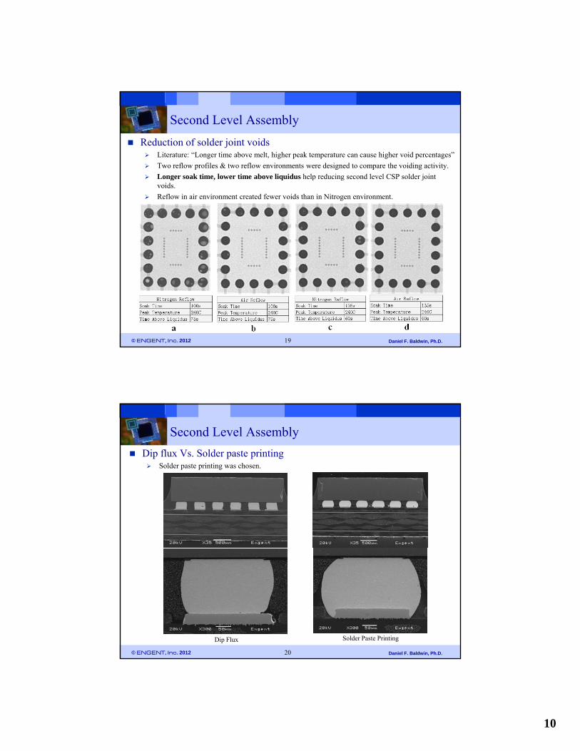
Reduction of solder joint voids Voids were found in the second level CSP solder joints.
Too many voids or overly large voids can affect the solder joint quality.
Voids reduce the area of intermetallic compound formation when the voids are formed on the solder wetting area.
© ENGENT, Inc. 2012 Daniel F. Baldwin, Ph.D.18
CSP Solder Joint Voiding
10
Second Level Assembly
Reduction of solder joint voids Literature: “Longer time above melt, higher peak temperature can cause higher void percentages”
Two reflow profiles & two reflow environments were designed to compare the voiding activity.
Longer soak time lower time above liquidus help reducing second level CSP solder joint Longer soak time, lower time above liquidus help reducing second level CSP solder joint voids.
Reflow in air environment created fewer voids than in Nitrogen environment.
Reflow condition “d” was chosen.
© ENGENT, Inc. 2012 Daniel F. Baldwin, Ph.D.19
Second Level Assembly
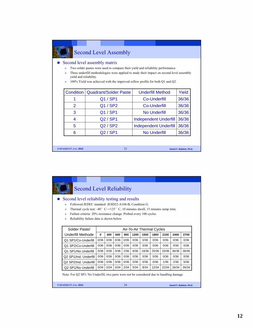
Dip flux Vs. Solder paste printing Solder paste printing was chosen.
© ENGENT, Inc. 2012 Daniel F. Baldwin, Ph.D.20
Dip Flux Solder Paste Printing

11
Second Level Assembly
Co-Underfill Vs. Independent Underfill for Q1 Another issue found was the Q1 first level underfill encroachment on the CSP solder balls.
The structure of Q1 created difficulty for the first level capillary underfill application and the underfill dispensed tend to flow onto the CSP ballsunderfill dispensed tend to flow onto the CSP balls.
Yield dropped due to this issue for Q1 second level assembly.
One solution was to use a smaller gauge dispense needle. It was low throughput and did not totally eliminate the possibility of underfill encroachment issue.
© ENGENT, Inc. 2012 Daniel F. Baldwin, Ph.D.21
1st Level Underfill Encroachment- 25 Gauge
Dispense Needle
Solution - 32 Gauge Dispense Needle
(Low Throughput)Cross section of initial Q1 second level assembly
Second Level Assembly
Co-Underfill Vs. Independent Underfill for Q1 Another solution was to use Co-underfill process: underfill 1st and 2nd level at the same time.
Unferfill flow speed control was important during the co-underfill process.
Too fast nderfill flo speed co ld trap air in the smaller gap bet een flip chip and CSP Too fast underfill flow speed could trap air in the smaller gap between flip chip and CSP, which could cause failure during thermal cycle.
Reduced the underfill flow speed by using a lower underfill process temperature.
© ENGENT, Inc. 2012 Daniel F. Baldwin, Ph.D.22
Underfill voids around 1st level solder joints which led to failure in thermal cycle test
Underfill around 1st level solder joints using a reduced underfill flow speed
12
Second Level Assembly
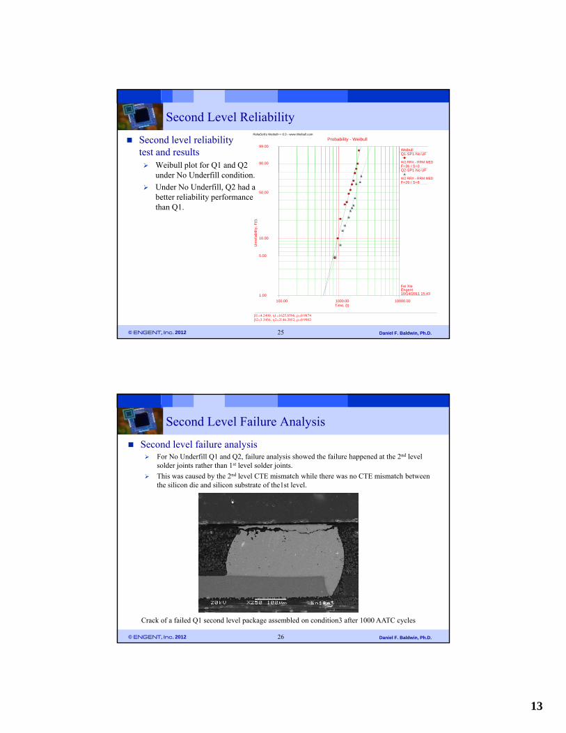
Second level assembly matrix Two solder pastes were used to compare their yield and reliability performance.
Three underfill methodologies were applied to study their impact on second level assembly yield and reliabilityyield and reliability.
100% Yield was achieved with the improved reflow profile for both Q1 and Q2.
Condition Quadrant/Solder Paste Underfill Method Yield
1 Q1 / SP1 Co-Underfill 36/36
2 Q1 / SP2 Co-Underfill 36/36
3 Q1 / SP1 No Underfill 36/36
© ENGENT, Inc. 2012 Daniel F. Baldwin, Ph.D.23
4 Q2 / SP1 Independent Underfill 36/36
5 Q2 / SP2 Independent Underfill 36/36
6 Q2 / SP1 No Underfill 36/36
Second Level Reliability
Second level reliability testing and results Followed JEDEC standard: JESD22-A104-B, Condition G.
Thermal cycle test: -40°C~+125°C, 10 minutes dwell, 15 minutes ramp time.
Fail re criteria: 20% resistance change Probed e er 100 c cles Failure criteria: 20% resistance change. Probed every 100 cycles.
Reliability failure data is shown below.
Solder Paste/
Underfill Methode
Air-To-Air Thermal Cycles0 300 600 900 1200 1500 1800 2100 2400 2700
Q1 SP1/Co-Underfill 0/36 0/36 0/36 0/36 0/36 0/36 0/36 0/36 0/36 0/36
Q1 SP2/Co-Underfill 0/36 0/36 0/36 0/36 0/36 0/36 0/36 0/36 0/36 0/36
Q1 SP1/No Underfill 0/36 0/36 0/36 2/36 8/36 18/36 25/36 33/36 36/36 36/36
© ENGENT, Inc. 2012 Daniel F. Baldwin, Ph.D.24
Q1 SP1/No Underfill 0/36 0/36 0/36 2/36 8/36 18/36 25/36 33/36 36/36 36/36
Q2 SP1/Ind. Underfill 0/36 0/36 0/36 0/36 0/36 0/36 0/36 0/36 0/36 0/36
Q2 SP2/Ind. Underfill 0/36 0/36 0/36 0/36 0/36 0/36 0/36 1/36 2/36 5/36
Q2 SP1/No Underfill 0/34 0/34 0/34 2/34 5/34 8/34 12/34 22/34 26/34 26/34
Note: For Q2 SP1/ No Underfill, two parts were not be considered due to handling damage
13
Second Level Reliability
Second level reliability test and results Weibull plot for Q1 and Q2
d N U d fill di i
90.00
99.00
ReliaSoft's Weibull++ 6.0 - www.Weibull.com
Probability - Weibull
WeibullQ1-SP1-No UF
W2 RRX - RRM MEDF=36 / S=0Q2-SP1-No UF
under No Underfill condition.
Under No Underfill, Q2 had a better reliability performance than Q1.
5 00
10.00
50.00
Unr
elia
bili
ty,
F(t
)
W2 RRX - RRM MEDF=26 / S=8
© ENGENT, Inc. 2012 Daniel F. Baldwin, Ph.D.25
100.00 10000.001000.00
1.00
5.00
Time, (t)
10/14/2011 15:43EngentFei Xie
Second Level Failure Analysis
Second level failure analysis For No Underfill Q1 and Q2, failure analysis showed the failure happened at the 2nd level
solder joints rather than 1st level solder joints.
This was caused by the 2nd level CTE mismatch while there was no CTE mismatch between This was caused by the 2 level CTE mismatch while there was no CTE mismatch between the silicon die and silicon substrate of the1st level.
© ENGENT, Inc. 2012 Daniel F. Baldwin, Ph.D.26
Crack of a failed Q1 second level package assembled on condition3 after 1000 AATC cycles
14
Summary and Conclusions
Robust yield was achieved on both fine and coarser pitch 3D-WLCSP second level assembly.
An air reflow environment and the reflow profile with higher soak time, lower k t t d ti b li id f d t d id t thpeak temperature and time above liquidus were found to reduce voids at the
CSP solder joints.
Co-underfill process was studied to overcome the first level underfill encroachment on Q1 package. A lower underfill process temperature could reduce the underfill voids during the co-underfill process.
Two solder pastes and three different underfill methodologies were evaluated for the 3D WLCSP second level assembly.
Th li bili b h fi l l d d l l k
© ENGENT, Inc. 2012 Daniel F. Baldwin, Ph.D.30
The reliability assessment on both first level and second level packages showed that 3D-WLCSP packages can be manufactured with robust yields and high thermal cycle reliability.