3D Trajectory Synthesis and Control for a Legged Swimming ...
8
3D Trajectory Synthesis and Control for a Legged Swimming Robot David Meger 1 , Florian Shkurti 1 , David Cort´ es Poza 1 , Philippe Gigu` ere 2 and Gregory Dudek 1 Abstract— Inspection and exploration of complex underwater structures requires the development of agile and easy to program platforms. In this paper, we describe a system that enables the deployment of an autonomous underwater vehicle in 3D environments proximal to the ocean bottom. Unlike many previous approaches, our solution: uses oscillating hydrofoil propulsion; allows for stable control of the robot’s motion and sensor directions; allows human operators to specify detailed trajectories in a natural fashion; and has been successfully demonstrated as a holistic system in the open ocean near both coral reefs and a sunken cargo ship. A key component of our system is the 3D control of a hexapod swimming robot, which can move the vehicle through agile sequences of orientations de- spite challenging marine conditions. We present two methods to easily generate robot trajectories appropriate for deployments in close proximity to challenging contours of the sea floor. Both offline recording of trajectories using augmented reality and online placement of fiducial tags in the marine environment are shown to have desirable properties, with complementary strengths and weaknesses. Finally, qualitative and quantitative results of the 3D control system are presented. I. INTRODUCTION This paper presents a number of tightly integrated control and human robot interface (HRI) components, developed for the hexapod autonomous underwater vehicle (AUV), Aqua [1], which enable agile, 3D, terrain-adapted trajectories. A 6-DOF motion controller extends the previous quasi-planar 2D operating modes of our vehicle while maintaining stabil- ity and responsiveness. Additionally, we describe two HRI paradigms that are convenient enough to be deployed by non- expert and preoccupied support divers but also rich enough to describe dynamic motions through space. The combined system has been evaluated during a recent sea trial where it performed numerous tasks that would have been impossible for previous iterations of our vehicle (e.g., autonomously tracing the 3D contour of a shipwreck, shown in Figure 1). The core of our method is a trajectory controller that allows a swimming robot propelled by oscillating hydrofoils to track almost arbitrary 6-DOF motions rapidly, but stably. Examples of these motions are provided in Figure 2. Aqua’s propulsion system is based on the periodic motion (i.e., kicking) of 6 independent flippers, so a careful accounting of forces and attitudes is required. Our controller com- bines robust computation of 6-DOF quantities, such as the body-frame commands required to meet world-frame con- straints, spherical linear interpolation to find shortest paths in rotation-space, and model-free feedback control. To address 1 Mobile Robotics Lab, Centre for Intelligent Machines, McGill Univer- sity {dmeger,florian,davidcp,dudek}@cim.mcgill.ca 2 D´ epartement d’informatique et g´ enie logiciel, Facult´ e de science et g´ enie, Universit´ e Laval [email protected] Fig. 1. The Aqua robot completes a vertical climb alongside a cargo vessel that rests on the ocean floor, prompted by a visual marker placed next to the ship by a human operator, seen near A. This is one of many new stable behaviors made possible by our technique. Image best viewed in color. the practical challenge of tuning controller gains in new and variable environmental conditions, our system performs semi-autonomous gain selection, with the robot searching subsets of the parameter space interspersed with oversight from an operator. The trajectory controller opens the door for countless behaviors and applications ranging from fish tracking to hull inspection. While a full sensor autonomy system would be well served by such a motion controller, in the current work we consider the common model of a collaborative team of human divers and their robot assistant. Underwater HRI is well-documented to be challenging due to the limited mobility and cognitive load facing human divers. We present two HRI schemes based on visual fiducial markers: design via augmented reality and terrain-based tag programming. Both methods are simple to understand and well-suited to describing the types of 3D motion that we seek. A key aspect of this work is that it allows a human mediator (i.e. a scuba diver) to specify the robot trajectories in real time and to adapt trajectories to the undersea environment. The next section will describe existing systems and high- light the novelty of the work presented here. We will then describe our legged swimming platform and the novel 3D control regime that we have employed. Section IV describes the HRI programming tools that we have developed. Our experimental section provides quantitative analysis of the control performance and reports the results of deploying the HRI approaches in complex subsea locales. Finally, we will outline future work.
Transcript of 3D Trajectory Synthesis and Control for a Legged Swimming ...

3D Trajectory Synthesis and Control for a Legged Swimming Robot
David Meger1, Florian Shkurti1, David Cortes Poza1, Philippe Giguere2 and Gregory Dudek1
Abstract— Inspection and exploration of complex underwaterstructures requires the development of agile and easy toprogram platforms. In this paper, we describe a system thatenables the deployment of an autonomous underwater vehiclein 3D environments proximal to the ocean bottom. Unlike manyprevious approaches, our solution: uses oscillating hydrofoilpropulsion; allows for stable control of the robot’s motion andsensor directions; allows human operators to specify detailedtrajectories in a natural fashion; and has been successfullydemonstrated as a holistic system in the open ocean near bothcoral reefs and a sunken cargo ship. A key component of oursystem is the 3D control of a hexapod swimming robot, whichcan move the vehicle through agile sequences of orientations de-spite challenging marine conditions. We present two methods toeasily generate robot trajectories appropriate for deploymentsin close proximity to challenging contours of the sea floor. Bothoffline recording of trajectories using augmented reality andonline placement of fiducial tags in the marine environmentare shown to have desirable properties, with complementarystrengths and weaknesses. Finally, qualitative and quantitativeresults of the 3D control system are presented.
I. INTRODUCTION
This paper presents a number of tightly integrated controland human robot interface (HRI) components, developed forthe hexapod autonomous underwater vehicle (AUV), Aqua[1], which enable agile, 3D, terrain-adapted trajectories. A6-DOF motion controller extends the previous quasi-planar2D operating modes of our vehicle while maintaining stabil-ity and responsiveness. Additionally, we describe two HRIparadigms that are convenient enough to be deployed by non-expert and preoccupied support divers but also rich enoughto describe dynamic motions through space. The combinedsystem has been evaluated during a recent sea trial where itperformed numerous tasks that would have been impossiblefor previous iterations of our vehicle (e.g., autonomouslytracing the 3D contour of a shipwreck, shown in Figure 1).
The core of our method is a trajectory controller thatallows a swimming robot propelled by oscillating hydrofoilsto track almost arbitrary 6-DOF motions rapidly, but stably.Examples of these motions are provided in Figure 2. Aqua’spropulsion system is based on the periodic motion (i.e.,kicking) of 6 independent flippers, so a careful accountingof forces and attitudes is required. Our controller com-bines robust computation of 6-DOF quantities, such as thebody-frame commands required to meet world-frame con-straints, spherical linear interpolation to find shortest paths inrotation-space, and model-free feedback control. To address
1Mobile Robotics Lab, Centre for Intelligent Machines, McGill Univer-sity {dmeger,florian,davidcp,dudek}@cim.mcgill.ca
2Departement d’informatique et genie logiciel, Faculte de science etgenie, Universite Laval [email protected]
Fig. 1. The Aqua robot completes a vertical climb alongside a cargo vesselthat rests on the ocean floor, prompted by a visual marker placed next tothe ship by a human operator, seen near A. This is one of many new stablebehaviors made possible by our technique. Image best viewed in color.
the practical challenge of tuning controller gains in newand variable environmental conditions, our system performssemi-autonomous gain selection, with the robot searchingsubsets of the parameter space interspersed with oversightfrom an operator.
The trajectory controller opens the door for countlessbehaviors and applications ranging from fish tracking tohull inspection. While a full sensor autonomy system wouldbe well served by such a motion controller, in the currentwork we consider the common model of a collaborativeteam of human divers and their robot assistant. UnderwaterHRI is well-documented to be challenging due to the limitedmobility and cognitive load facing human divers. We presenttwo HRI schemes based on visual fiducial markers: designvia augmented reality and terrain-based tag programming.Both methods are simple to understand and well-suited todescribing the types of 3D motion that we seek. A key aspectof this work is that it allows a human mediator (i.e. a scubadiver) to specify the robot trajectories in real time and toadapt trajectories to the undersea environment.
The next section will describe existing systems and high-light the novelty of the work presented here. We will thendescribe our legged swimming platform and the novel 3Dcontrol regime that we have employed. Section IV describesthe HRI programming tools that we have developed. Ourexperimental section provides quantitative analysis of thecontrol performance and reports the results of deploying theHRI approaches in complex subsea locales. Finally, we willoutline future work.

Fig. 2. Six example motions shown are from the larger set achievable by our 3D controller. Red arrows indicate directions of motion, explicitly namedsurge (robot’s X direction) and heave (robot’s Z direction), as indicated. No sway motions (robot’s Y direction) are shown since our robot cannot producethrust in this dimension. Previous work on the Aqua vehicle almost exclusively focused on motions in the left-most column, which also represent the leastchallenging control problems.
II. RELATED WORKThe problem of designing and controlling stable AUVs has
been studied by many authors [2], [3], [4], [5] on a varietyof platforms. While techniques range widely depending onvehicle characteristics and goals, feedback control on orien-tation sensors is a common theme. While controllers basedon fluid dynamics properties can be accurate, they are alsooften complex. In our case, deployment on a physical robotwith limited computing resources was essential, precludingintensive flow dynamic simulations. Rather, we employ asimple, but practical linear feedback controller [6].
Previous authors have undertaken hydrodynamic motionanalysis for the Aqua vehicle itself [7], [8], [9]. This workhas yielded several versions of a model-based controller forsimple input commands. These controllers allowed for onlyone angular dimension at a time to vary from the standarddownward looking configuration and considered a singlefixed forward thrust.
Humans dynamically adapt the way we move based onconditions, and this same behaviour is crucial for robots.In the underwater domain, [10] notes that gain schedulingis needed for stable control of a swimming robot acrossmultiple speeds due to nonlinear drag effects. Online param-eter tuning for a swimming vehicle controller was suggestedby [11], although their work considers only the theoreticalaspects of the problem and only discusses the optimization
of a single parameter value. We consider control of thevehicle at arbitrary body orientations and at a variety ofspeeds (consider Figure 2). This introduces a wide rangeof disturbances, and modes of propulsion, and has motivatedour development of semi-autonomous gain selection.
Our work differs notably from prior studies that usecameras for semi-autonomous underwater operation [1], [12],[13], [14], [15], in particular due to the complex and vision-guided trajectories we consider. As we descend very near tounderwater structures, 3D motions such as those we developare essential to avoid the plentiful obstacles and the pathsbetween obstacles become more complex to design, requiringHRI solutions.
III. 3D TRAJECTORY CONTROL FOR LEGGEDSWIMMING ROBOTS
This section describes a feedback controller that allowsour vehicle to swim precise trajectories in the space of3D attitude and depth. This module closes the loop aroundthe vehicle’s sensors, producing flipper rotation (kicking)commands based on the error between the robot’s currentand target states. We build upon an existing low-level gaitgenerator, which translates desired thrusts in the robot frameinto flipper motions in an open loop fashion. The gaitgenerator has previously been paired with a 2D attitudecontroller that achieved stable flat swimming [1]. This paper

Fig. 3. The 3D coordinate frames involved in our control problem.
represents the first demonstration of controlling the Aquavehicle under arbitrary 3D attitudes.
Control in 3D requires mapping all necessary sensor andmotion data into a common coordinate frame, as visualizedin Figure 3. We correct positional errors in depth usingcomputations robust to being upside-down or vertical. Inorder to stabilize motions and to reject disturbances, weimplement PD control using an inertial measurement unit(IMU) and a depth sensor as feedback. As our robot isnon-holonomic, jointly satisfying target depth and attitudeare conflicting goals. We employ a cascade controller [6],composed of a depth loop surrounding an attitude loop,to mediate between factors. This prioritizes depth control,which is important for safe operations underwater. Thefinal component of our system is a semi-autonomous gainadaptation behaviour that allows human operators to moreeasily optimize controllers for a family of motions and toadapt to changing environmental conditions.
A. Hexapod Swimming Gaits
The mapping between a desired motion of the robot’s bodyand the required leg movements is highly complex, as itinvolves interactions in the force-domain between the variouslegs, the hydrodynamics created when vortices from oneleg are “shed” to the next, and interactions with exogenousfactors such as ocean currents. Simple swimming strategies,called gaits, have been developed in previous publications(e.g., [1]). In this work, we re-use the existing gait moduleand describe its properties and inputs here as background.
Gaits rely on hand-crafted behaviors that coordinate mo-tions of the six flippers. These behaviors are based on an ab-straction that approximates the flippers as steerable thrusters.Under this approximation, absolute thrust can be controlledvia the oscillation amplitude and its direction by changing anoffset angle around which the oscillation is performed. Bycombining the action of these six virtual thrusters, simple ratecommands (either angular or translational) can be executedin open-loop. For example, a pure rolling motion can be
Fig. 4. An overview schematic of our vehicle controller.
achieved by having all the left virtual thrusters pointingupwards and the right virtual thrusters pointing downward.
The gait controller accepts 5 of 6 possible instantaneousthrusts. Sway, along the robot’s Y axis, is not possible due tothe physical orientation of the flippers, making this vehiclenon-holonomic. Therefore, the input to the gait module is 5vehicle frame desired thrusts at each time: roll, pitch, yaw,heave and surge. Due to inherent approximations and theneed to re-orient the flippers to achieve a new thrust, theactual response of the robot to any requested motion is diffi-cult to model and may have complex time-domain properties.This motivates our pursuit of a closed-loop attitude controllerto drive the gaits.
B. Feedback Control for 3D Swimming
1) Inputs: Our controller receives target trajectories fromthe users and data from the sensors as its inputs. A trajectoryis an n length sequence, pn = {p1, ..., pn}, where eachelement, pi = {qi, fi, hi}, specifies a target global frameorientation in quaternion form, qtarget, vehicle frame heaveand surge thrusts, ftarget and depth below the water’ssurface, htarget. A 3DM-GX1 IMU from Microstrain Inc.measures the vehicle’s orientation, acceleration, and angularvelocity. In this work, we utilize only the orientation readingas a quaternion, W
V q, which represents the vehicle’s attitudein the IMU’s reference (or world) frame. A pressure sensorreads the depth below the surface of the water, hcurrent.
2) Coordinate Frames: The first step in achieving 3Dcontrol is the correct handling of the multiple frames ofreference related to various system quantities. The IMU’sreference frame, defined by the gravity vector, acts as ourworld coordinates. This implies that the ideal behavior is forthe robot to move such that the IMU readings exactly matchthe commanded orientations. The robot’s gait controlleraccepts instantaneous vehicle frame velocity commands, sowe must robustly transform geometric information betweenthe two frames. Our depth sensor is located at the back ofthe vehicle, so its readings must be corrected based upon thevehicle’s current orientation.
3) Depth Control Loop: The depth control loop, shown inFigure 4, is responsible for modifying the robot’s orientationsuch that it will climb or descend to maintain a specifiedtarget depth, htarget. The robot can produce a motion alongthe global Z axis by modifying its orientation to directthrust as needed. In symbols, the target orientation qtargetis modified to achieve this Z motion via a depth-correcting

rotation qdepth. The final target angle to the inner controllertakes the form
qadjusted = qdepth ⊗ qtarget (1)
with ⊗ representing quaternion multiplication. We deriveqdepth by forming a quaternion from the unit vector, k, andangle of rotation about that vector, θ, as
qdepth =
kxsin(θ/2)kysin(θ/2)kzsin(θ/2)cos(θ/2)
. (2)
The angle of rotation, specified by vector k, is selectedto achieve climb or descent as needed, accounting for thecurrent thrust direction. This desired vector is perpendicularto both the vehicle’s world frame thrust and the world Zaxis, so it can be computed using the cross product
k = (WV qV ftarget)×
001
. (3)
The magnitude of rotation towards the desired depth, θ, isdetermined by a PD controller, based on the current deptherror, εh = htarget − hcurrent, as
θ = KdepthP εh −Kdepth
D
dεhdt
. (4)
This correction angle is capped to ±45◦ to limit the climbrate of the robot, which is desirable when operated inconjunction with human divers who cannot safely changedepth rapidly. Our nested controller can become susceptibleto oscillation, as there are two dependent levels of feedbackoccurring. For this reason, we have found that derivativecontrol within the depth loop, Kdepth
D is essential.4) Attitude Control Loop: Our controller’s inner loop
attempts to generate gait commands that bring the orientationof the vehicle, qcurrent, to the orientation requested by theouter loop, qadjusted. Each of these quantities is a rotationin 3D and so their difference, our control error, cannotsimply be computed by subtraction. Instead, we considerthe distance of the shortest path through the space SO(3).Topographically, this shortest path is the great circle alongthe unit sphere which connects the unit vectors representingthe two orientations. Our goal is to drive the robot alongsuch a path through angle-space until it arrives at the targetangle qadjusted.
In order to send instantaneous commands, we extract thecurrent local orientation change needed to progress along theangle-space path. This interpolation of the path into smallsegments along the great circle is referred to as sphericallinear interpolation (SLERP) [16]. It produces a world framerotation error
W εq = SLERP (qcurrent, qadjusted, u) (5)
with interpolation parameter u controlling the size of theangle step. The underlying gait controller accepts vehicle
frame thrust commands, so this world frame angle step mustbe transformed into the robot’s coordinates
V εq = VW qW εq. (6)
Finally, we extract the components of V εq in the roll,pitch and yaw Euler angle representation accepted by thegait module: εr, εp and εy . PD feedback control is appliedin order to output unitless rate commands compatible withthe gait module, in the roll, pitch and yaw axes
rgait = KrP εr −Kr
D
dεrdt
(7)
pgait = KpP εp −K
pD
dεpdt
(8)
ygait = KyP εy −K
yD
dεydt
(9)
In order to reduce the noise amplification effects of signaldifferencing, a first-order Infinite Impulse Response filterwith a time-constant period on the order of one cycle ofleg motion (∼ 250 ms) is applied to smooth each signal.This also alleviates the issue of unwanted oscillations due tothe periodic nature of the gait.
C. Online Gain Adaptation
Our robot is non-spherical, which causes highly varyingdisturbances as the robot changes orientation. For example,swimming directly forward causes the narrow and roundedfront shell to cut through the water, while so called heavemotions push large amounts of water with the flat top of therobot. The measured drag ratio between these different mo-tions is roughly a full order of magnitude (10x). To achievestable motion in both cases, different sets of controller gainsare required for each motion, slowing the development ofan agile system. To address this, we have developed a semi-automated procedure to select our controller’s gains in novelsituations.
The robot adapts its controller gains while swimming bysearching for parameters that minimize control error overshort sequences. While numerous parameter search methodscould be viable, we have implemented an efficient coordinatedescent, which selects one parameter dimension at a time,line searching over values of each dimension, fixing the mini-mum value obtained, and then moving to the next dimension.We will describe the efficacy of this search procedure in ourexperimental results, but for now we make several observa-tions about its desirable properties. We note that our approachcan operate without a model of the robot’s control systemor its disturbances – it is model-free. Coordinate descentalso has the important practical advantage of maintainingthe majority of parameter dimensions unchanged in any givenstep, so that the robot’s effective behavior changes slowly andsafety can be maintained. In underwater robotics, the safetyof nearby humans and the marine ecosystem are paramount.A final advantage of modifying a single parameter at a timeis to build the confidence of human operators and to facilitateoffline interpretation of the test results by a human, animportant consideration in mixed-initiative robot operations.

Fig. 5. A human operator specifies a looping trajectory using ouraugmented reality interface. Note that the swimming robot that appears ineach image is rendered by computer graphics and is not physically present.The rendered pose of the robot reflects a point along the trajectory, whichis stored in a format suitable for input to our trajectory controller. Later, therobot replays the specified path with high fidelity, in this case swimming ina vertical loop.
IV. SYNTHESIZING 3D UNDERWATERTRAJECTORIES
In challenging underwater environments, semi-autonomous operation is often preferred. Full sensor-guidedautonomy is not within the reach of most platforms dueto cost, reliability, or other limitations. For example, theclose-to-object operations that we study here must occur inrelatively deep water, which precludes the use of a GPSantenna and acoustic underwater localizers add significantfinancial overhead. However, human scientists regularlyparticipate in the day-to-day routine of underwater scienceand are a reliable source of guidance. We describe severaltechniques that allow an operator to synthesize detailed 3Dunderwater trajectories suitable for our vehicle, which wehave developed and tested in the ocean.
A. Parameterized-Shape Trajectories
Our first approach allows a human operator to specifytarget robot trajectories by composing segments of param-eterized shapes, such as squares and circles, with differentorientation, speed and depth settings for each individualshape. In principle, by careful choice of the parameters andpotentially the use of a very large number of segments, theoperator is able to produce any arbitrary trajectory. However,choosing the shape family and parameters is difficult tovisualize even in a lab scenario, and is essentially impossiblefor a diver in deep water. So, we have continued to considerseveral more convenient synthesis paradigms.
B. Trajectory Design via Augmented Reality
Our second synthesis approach is inspired by the notionof a human “conductor” forming paths with natural gesturesthat the robot mimics afterwards. To assist the operatorin visualizing the scenario our system provides augmented
reality feedback in the form of a virtual robot rendered on topof the live image feed. The response of the augmented realityrobot allows easy comprehension of what will be the realrobot’s target behaviour during trajectory playback. Figure5 provides an example of the human operator recording atrajectory. A sample of the corresponding robot motion canbe seen in the video submission accompanying this paper,which is also available on the Internet1.
Mapping human hand motion into robot swimming motionrequires a translation between two different physical spaces.Several mappings have been considered during our systemdevelopment and the following was reported by the operatorto be well suited for the task due to its simple intuitive nature:
• The position of the tag along the camera’s viewingdirection is mapped to the robot depth’s below the watersurface.
• Changes in the position of the tag in the camera’simage plane between video frames are projected ontothe forward direction of the robot to determine its surge.
• Rotations of the tag are mapped to rotations of the robot.Although we postpone full evaluation of this HRI
paradigm for future work, we received significant positivefeedback from test operators. The robot was able to performa number of trajectories in the ocean, both near reefs and asunken ship, collecting valuable sensory data while operatingsafely without environmental impact.
C. Terrain-Based Programming
The final trajectory synthesis method that we studied fo-cuses on achieving very close proximity between the vehicleand the terrain. While each of the previous methods allowsfor the construction of trajectories that conform loosely tothe shape of the sea floor, the vehicle operates withoutfeedback during trajectory execution, which means that areasonable safety margin must be maintained. The approachthat we refer to as Terrain-Based Programming utilizesvisual fiducial markers placed by human operators in theenvironment itself in order to achieve precise near-terraintrajectories. The robot detects the visual markers using itscameras, which is reliable due to the highly distinctive natureof the visual patterns and the robust image processing usedfor detection [17]. Each time that the robot detects a tag, itrecovers an unique numeric ID and solves for the relativepose between its camera and the tag.
A vocabulary, known to the human operators, maps be-tween available tag IDs and the matching motions. Theoperators construct a desired robot trajectory by choosingthe position and orientation of several tags, so that eachwill be seen by the robot after it completes execution ofthe previous motion. Tags are often placed at key landmarksin the environment, for example to enable the robot toavoid a sensitive obstacle, and at points of desired robotbehaviour change, for example where a local visual surveyshould be conducted. The relative pose between the robot
1Address: http://www.cim.mcgill.ca/˜dmeger/IROS2014_3DTrajectories/

Fig. 6. Roll tracking with various gains attempted automatically by the robot during a line-search run conducted in the ocean. The error summary on theright shows that the gain value 0.55 produced minimal error and was selected. Note that the snowplow motion shown here pushes significant amounts ofwater in front of the robot, causing large natural disturbances, and large errors compared to other motions. This is one of the most challenging elementarymotions to control on the Aqua vehicle.
and the tag acts as a global frame position correction and caninfluence the robot behaviour, such as to remove drift. Figure8 provides an example of tag-based shipwreck inspection. Wewill discuss the specific vocabulary used and resulting robottrajectory in our experiments section.
V. EXPERIMENTS
We have evaluated our system in the open waters of theCaribbean Sea, off the coast of Barbados. In all cases, ateam of divers operated the Aqua vehicle without tether, pre-loading software and parameters to be executed when therobot had been brought to sufficient depths and conditions.In Section V-A, we quantitatively study the stability achievedby our depth and attitude controller over a range of desiredrobot trajectories. Here we do not focus on trajectoriesthat are particularly meaningful for the local terrain, butrather choose those that allow us to understand the system’sbehavior. Section V-B describes evaluation of our holisticsystem, including the trajectory synthesis, its flexibility andefficacy, as well as the control system’s ability to achievethat trajectory.
A. 3D Control Evaluation
Our initial set of ocean trials were conducted in tracts ofwater with few obstacles where the stability of our controllercould be verified and tuning could be done safely. Thecontroller was driven with several fixed swimming behaviors(i.e., each trajectory was composed simply of one orientationand speed, repeated for a duration). These trials were usedto observe the stability of our controller and to execute
TABLE ITRACKING ERROR FOR VARIOUS MOTION CLASSES. BOTH HELICAL
MOTIONS ROTATED THE ROBOT AT A CONSTANT 36◦ EACH SECOND
ABOUT ITS ROLL AXIS.
Roll Pitch Yaw DepthMotion Error Error Error Error
(deg) (deg) (deg) (m)Flat 0.4 1.6 0.3 0.05
Knife 1.7 3.0 1.1 0.06Snowplow 7.5 3.7 2.0 0.20
Circular Helix 7.2 6.3 6.0 0.11Square Helix 13.0 6.6 7.3 0.17
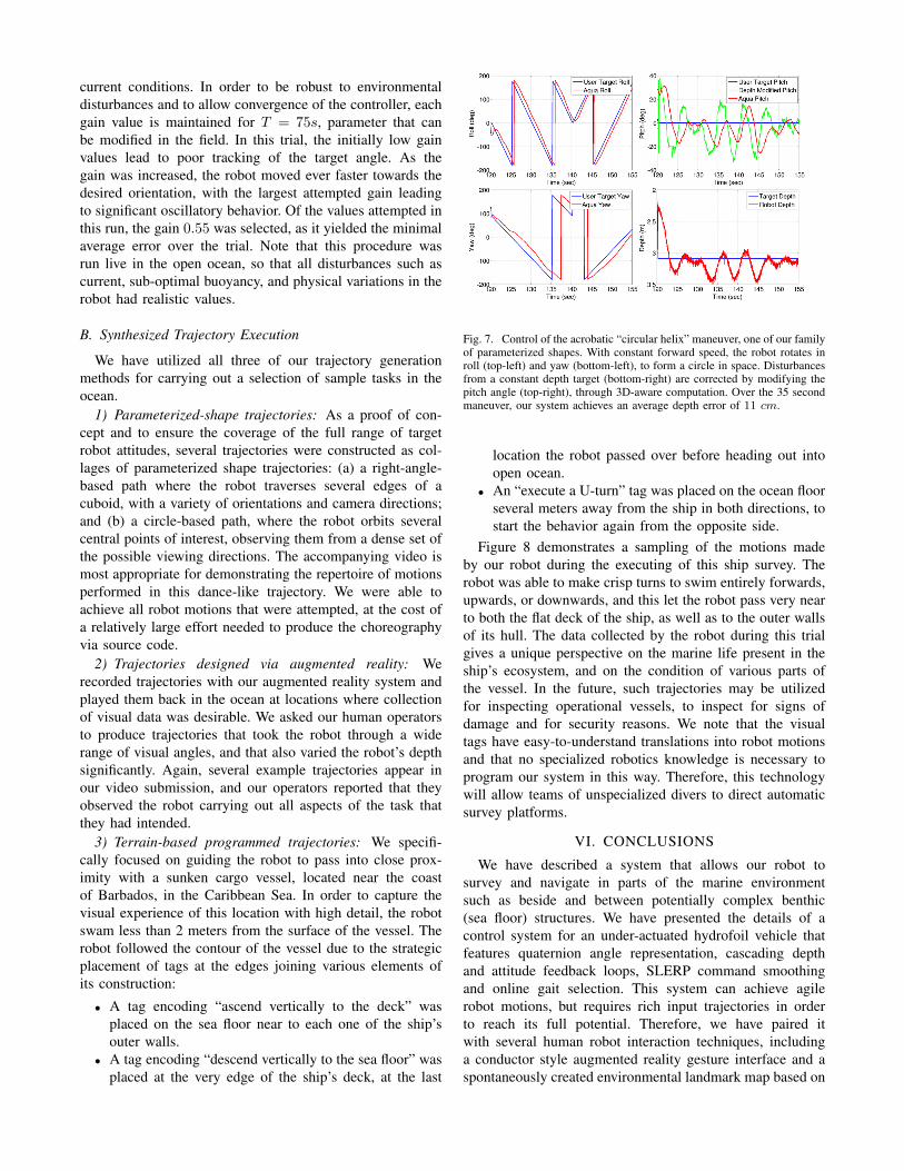
the online parameter optimization procedure. We have sum-marized the average errors for a variety of both simpleand composite robot motions in Table I. The increasingerrors are an indication of the difficulty level associatedwith each motion pattern. For example, the vertical heavemaneuver has a much larger drag force than the flat or knife-edge maneuvers. As mentioned earlier, this increase in dragrenders motion less stable. We additionally provide results onour controllers stability in Figure 7. The motion command, acircular helix, involves simultaneous and continuous changein all angular dimensions, which is a stress-test for an attitudecontroller. Maintaining depth errors within 11cm for thisbehaviour indicates a relatively well-tuned system.
We report results from semi-autonomous gain selection inFigure 6. In this case, the robot attempts to line-search overthe values of its roll proportional gain, r
PK, to find the valuewhich yields the minimal error swimming performance under
current conditions. In order to be robust to environmentaldisturbances and to allow convergence of the controller, eachgain value is maintained for T = 75s, parameter that canbe modified in the field. In this trial, the initially low gainvalues lead to poor tracking of the target angle. As thegain was increased, the robot moved ever faster towards thedesired orientation, with the largest attempted gain leadingto significant oscillatory behavior. Of the values attempted inthis run, the gain 0.55 was selected, as it yielded the minimalaverage error over the trial. Note that this procedure wasrun live in the open ocean, so that all disturbances such ascurrent, sub-optimal buoyancy, and physical variations in therobot had realistic values.
B. Synthesized Trajectory Execution
We have utilized all three of our trajectory generationmethods for carrying out a selection of sample tasks in theocean.
1) Parameterized-shape trajectories: As a proof of con-cept and to ensure the coverage of the full range of targetrobot attitudes, several trajectories were constructed as col-lages of parameterized shape trajectories: (a) a right-angle-based path where the robot traverses several edges of acuboid, with a variety of orientations and camera directions;and (b) a circle-based path, where the robot orbits severalcentral points of interest, observing them from a dense set ofthe possible viewing directions. The accompanying video ismost appropriate for demonstrating the repertoire of motionsperformed in this dance-like trajectory. We were able toachieve all robot motions that were attempted, at the cost ofa relatively large effort needed to produce the choreographyvia source code.
2) Trajectories designed via augmented reality: Werecorded trajectories with our augmented reality system andplayed them back in the ocean at locations where collectionof visual data was desirable. We asked our human operatorsto produce trajectories that took the robot through a widerange of visual angles, and that also varied the robot’s depthsignificantly. Again, several example trajectories appear inour video submission, and our operators reported that theyobserved the robot carrying out all aspects of the task thatthey had intended.
3) Terrain-based programmed trajectories: We specifi-cally focused on guiding the robot to pass into close prox-imity with a sunken cargo vessel, located near the coastof Barbados, in the Caribbean Sea. In order to capture thevisual experience of this location with high detail, the robotswam less than 2 meters from the surface of the vessel. Therobot followed the contour of the vessel due to the strategicplacement of tags at the edges joining various elements ofits construction:
• A tag encoding “ascend vertically to the deck” wasplaced on the sea floor near to each one of the ship’souter walls.
• A tag encoding “descend vertically to the sea floor” wasplaced at the very edge of the ship’s deck, at the last
Fig. 7. Control of the acrobatic “circular helix” maneuver, one of our familyof parameterized shapes. With constant forward speed, the robot rotates inroll (top-left) and yaw (bottom-left), to form a circle in space. Disturbancesfrom a constant depth target (bottom-right) are corrected by modifying thepitch angle (top-right), through 3D-aware computation. Over the 35 secondmaneuver, our system achieves an average depth error of 11 cm.
location the robot passed over before heading out intoopen ocean.
• An “execute a U-turn” tag was placed on the ocean floorseveral meters away from the ship in both directions, tostart the behavior again from the opposite side.
Figure 8 demonstrates a sampling of the motions madeby our robot during the executing of this ship survey. Therobot was able to make crisp turns to swim entirely forwards,upwards, or downwards, and this let the robot pass very nearto both the flat deck of the ship, as well as to the outer wallsof its hull. The data collected by the robot during this trialgives a unique perspective on the marine life present in theship’s ecosystem, and on the condition of various parts ofthe vessel. In the future, such trajectories may be utilizedfor inspecting operational vessels, to inspect for signs ofdamage and for security reasons. We note that the visualtags have easy-to-understand translations into robot motionsand that no specialized robotics knowledge is necessary toprogram our system in this way. Therefore, this technologywill allow teams of unspecialized divers to direct automaticsurvey platforms.
VI. CONCLUSIONS
We have described a system that allows our robot tosurvey and navigate in parts of the marine environmentsuch as beside and between potentially complex benthic(sea floor) structures. We have presented the details of acontrol system for an under-actuated hydrofoil vehicle thatfeatures quaternion angle representation, cascading depthand attitude feedback loops, SLERP command smoothingand online gait selection. This system can achieve agilerobot motions, but requires rich input trajectories in orderto reach its full potential. Therefore, we have paired itwith several human robot interaction techniques, includinga conductor style augmented reality gesture interface and aspontaneously created environmental landmark map based on

(1) (2) (3) (4)
(5) (6) (7) (8)
Fig. 8. A turn-by-turn account of one pass over the contour of a shipwreck. From left to right and top to bottom, the robot: (1) approaches from the sand;(2) views an “up” tag and ascends vertically along the ships hull; (3) crests at a depth above the deck; (4) swims flat above the deck; (5) views a “down”tag; (6) turns downwards; (7) descends near to the ship’s opposite side; and (8) finally levels out, again swimming flat over the sandy ocean bottom. Bestviewed in color.
a vocabulary of available actions. We have demonstrated theeffectiveness of these approaches in the Caribbean Sea, nearto several coral heads as well as a sunken cargo ship, withour robot able to achieve many desirable poses that wouldbe challenging or impossible for existing systems.
The demands of the marine environment, especially in thecontext of human-robot interaction, are substantial and theinteraction modalities we have outlined are merely sampleswhat can be achieved. The HRI aspect of our system willbe more formally verified and extended, potentially throughuse by interested marine biologists and oceanographers.
ACKNOWLEDGMENT
This work was supported by the Natural Sciences andEngineering Research Council of Canada (NSERC) throughthe NSERC Canadian Field Robotics Network (NCFRN) andby the McGill Tomlinson Postdoctoral Fellowship program.
REFERENCES
[1] G. Dudek, M. Jenkin, C. Prahacs, A. Hogue, J. Sattar, P. Giguere,A. German, H. Liu, S. Saunderson, A. Ripsman, S. Simhon, L. A.Torres-Mendez, E. Milios, P. Zhang, and I. Rekleitis, “A visuallyguided swimming robot,” in Proceedings of Intelligent Robots andSystems, Edmonton, Alberta, Canada, August 2005.
[2] S. Mohan and A. Thondiyath, “A non-linear tracking control schemefor an under-actuated autonomous underwater robotic vehicle,” Inter-national Journal of Ocean System Engineering, vol. 1, no. 3, pp. 120– 135, 2011.
[3] J. Vaganay, L. Gurfinkel, M. Elkins, D. Jankins, and K. Shurn, “Hov-ering autonomous underwater vehicle - system design improvementsand performance evaluation results,” in Proceedings of UnmannedUntethered Submersible Technology, 2009.
[4] D. Boskovic and M. Krstic, “Global attitude/position regulation forunderwater vehicles,” Inernational Journal of Systems Science, vol. 30,no. 9, pp. 939 – 946.
[5] D. Font, M. Tresanchez, C. Siegentahler, T. Pallej, M. Teixid,C. Pradalier, and J. Palacin, “Design and implementation of abiomimetic turtle hydrofoil for an autonomous underwater vehicle,”Sensors, vol. 11, no. 12, pp. 11 168–11 187, 2011.
[6] A. Visioli, Practical PID Control. Springer-Verlag, 2006.[7] C. Georgiades, “Simulation and control of an underwater hexapod
robot,” Master’s thesis, McGill University, 2005.[8] P. Giguere, G. Dudek, and C. Prahacs, “Characterization and modeling
of rotational responses for an oscillating foil underwater robot,” inProceedings of Intelligent Robots and Systems, Beijing, China, October2006.
[9] N. Plamondon and M. Nahon, “Trajectory tracking controller for anunderwater hexapod vehicle,” in Proceedings of Oceans, Quebec City,Canada, September 2008.
[10] P. Giguere, Y. Girdhar, and G. Dudek, “Wide-speed autopilot systemfor a swimming hexapod robot,” in Proceedings of Computer andRobot Vision, 2013.
[11] G. Bartolini and A. Pisano, “Black-box position and attitude trackingfor underwater vehicles by second-order sliding-mode technique,”International Journal of Robust and Nonlinear Control, vol. 20, no. 14,pp. 1594 – 1609, 2010.
[12] J. Sattar, P. Giguere, and G. Dudek, “Sensor-based behavior control foran autonomous underwater vehicle,” International Journal of RoboticsResearch (IJRR), vol. 28, no. 6, pp. 701–713, June 2009.
[13] R. Eustice, H. Singh, J. Leonard, M. Walter, and R. Ballard, “Visuallynavigating the rms titanic with slam information filters,” in Proceed-ings of Robotics: Science and Systems, Cambridge, USA, June 2005.
[14] M. Dunbabin, K. Usher, and P. Corke, “Visual motion estimation foran autonomous underwater reef monitoring robot.” in Proceedings ofField and Service Robotics, ser. Springer Tracts in Advanced Robotics,P. I. Corke and S. Sukkarieh, Eds., vol. 25. Springer, 2005, pp. 31–42.
[15] M. Bryson, M. Johnson-Roberson, O. Pizarro, and S. Williams, “Au-tomated registration for multi-year robotic surveys of marine benthichabitats,” in Proceedings of Intelligent Robots and Systems. IEEE,2013, pp. 3344–3349.
[16] K. Shoemake, “Animating rotation with quaternion curves,” in Pro-ceedings of ACM SIGGRAPH, 1985.
[17] M. Fiala, “Artag, a fiducial marker system using digital techniques,”in Proceedings of Computer Vision and Pattern Recognition, vol. 2,June 2005, pp. 590–596.