3D Scanning Method for Fast Motion using Single Grid ... · 3D Scanning Method for Fast Motion...
10
3D Scanning Method for Fast Motion using Single Grid Pattern with Coarse-to-fine Technique Ryo Furukawa Faculty of information sciences, Hiroshima City University, Japan [email protected] Hiroshi Kawasaki Faculty of engineering, Saitama University, Japan [email protected] Ryusuke Sagawa, Yasushi Yagi Institute of Scientific and Industrial Research, Osaka Univ., Japan {sagawa,yagi}@am.sanken.osaka-u.ac.jp Abstract An active 3D scanning method that can capture a fast motion is strongly required in wide areas. Since most commercial products using a laser pro- jector basically reconstruct the shape with a point or a line for each scan, a fast motion cannot be captured in principle. In addition, an extended method using a structured light can drastically reduce the number of projecting pat- terns, however, they still require several patterns and a fast motion cannot be captured. One solution for the purpose is to use a single pattern (one shot scan). Although, one shot scanning methods have been intensively studied, they often have stability problems and their result tend to have low resolution. In this paper, we develop a new system which achieves dense and robust 3D measurement from a single grid pattern. A 3D reconstruction can be achieved by identifying grid patterns using coplanarity constraints. We also propose a coarse-to-fine method to increase the density of the shape with a single pattern. 1 Introduction Currently active 3D scanners are widely used for actual 3D model acquisition process. Especially, coded structured light based systems have been intensively researched and commercialized, because systems of this type are relatively simple and realize high ac- curacy [1]. One of the significant drawbacks of the systems is that they require several patterns, and thus, a fast motion is difficult to be scanned in principle. To scan a 3D shape with fast motion, 3D scanning methods using a high-speed structured light system have been studied in recent years [5]. However, since the system still require a several frames for reconstruction, it cannot be applied to a fast motion in theory. BMVC 2008 doi:10.5244/C.22.67
Transcript of 3D Scanning Method for Fast Motion using Single Grid ... · 3D Scanning Method for Fast Motion...

3D Scanning Method for Fast Motion usingSingle Grid Pattern with Coarse-to-fine
Technique
Ryo FurukawaFaculty of information sciences, Hiroshima City University, Japan
Hiroshi KawasakiFaculty of engineering, Saitama University, Japan
Ryusuke Sagawa, Yasushi YagiInstitute of Scientific and Industrial Research, Osaka Univ., Japan
{sagawa,yagi}@am.sanken.osaka-u.ac.jp
Abstract
An active 3D scanning method that can capture a fast motion is stronglyrequired in wide areas. Since most commercial products using a laser pro-jector basically reconstruct the shape with a point or a line for each scan, afast motion cannot be captured in principle. In addition, an extended methodusing a structured light can drastically reduce the number of projecting pat-terns, however, they still require several patterns and a fast motion cannot becaptured. One solution for the purpose is to use a single pattern (one shotscan). Although, one shot scanning methods have been intensively studied,they often have stability problems and their result tend to have low resolution.In this paper, we develop a new system which achieves dense and robust 3Dmeasurement from a single grid pattern. A 3D reconstruction can be achievedby identifying grid patterns using coplanarity constraints. We also proposea coarse-to-fine method to increase the density of the shape with a singlepattern.
1 Introduction
Currently active 3D scanners are widely used for actual 3D model acquisition process.Especially, coded structured light based systems have been intensively researched andcommercialized, because systems of this type are relatively simple and realize high ac-curacy [1]. One of the significant drawbacks of the systems is that they require severalpatterns, and thus, a fast motion is difficult to be scanned in principle. To scan a 3D shapewith fast motion, 3D scanning methods using a high-speed structured light system havebeen studied in recent years [5]. However, since the system still require a several framesfor reconstruction, it cannot be applied to a fast motion in theory.
BMVC 2008 doi:10.5244/C.22.67

To overcome the aforementioned problems, ‘one-shot’ structured light systems thatuse only single images have been studied. Widely used methods in this category areembedding positional information of the projectors’ pixels into spatial patterns of the pro-jected images [7, 12]. Although the techniques can resolve the issues of rapid motionsand synchronization; since multiple pixels are required to encode a single positional in-formation into the patterns, resolution of the reconstructed shape is usually sparse. Inaddition, patterns of complex intensities and colors are usually used to encode positionalinformation into local areas, the assumptions of smooth surface or simple texture is re-quired; and if the assumptions do not hold, the decoding process of the patterns may beeasily affected and leads to unstable reconstruction.
In this paper, a 3D scanning method which can capture a 3D shape with fast motionfrom a single image, even if the objects do not have either smooth surface or uniformtexture, is presented. To achieve this, the system using a simple grid pattern formed bystraight lines distinguishable only as vertical or horizontal lines and its solutions based oncoplanarity constraints are utilized [4, 8]. Since the lines are required to be categorizedinto only two types, the image processing becomes simple and stable. In addition, thereis no need to encode particular information for the local grid pattern itself, so the patterncan be dense as long as it is extractable. We also propose a coarse-to-fine technique toincrease the density of the shape.
2 Related works
Shape reconstruction techniques with a structured light system, which encode positionalinformation of a projector into temporal or spatial changes in a projected pattern, havebeen largely investigated and summarized in [1, 14]. A technique using only temporalchanges is easy to implement, so it has commonly been used thus far [2, 6]. Since thetechnique uses multiple patterns necessary for decoding, it requires special attention to beapplied to high-speed capturing.
Techniques using only spatial encoding of a pattern allow scanning with only a single-frame image [7, 11, 12]. They typically use complex patterns or colors for phase unwrap-ping process and require assumptions of smooth or continuous surface or uniform texture,either locally or globally. If the assumptions do not hold, the decoding process of the pat-terns may be easily affected and leads to ambiguities near depth or color discontinuities.
Several research reducing the required number of patterns using both temporal andspatial changes were presented [5, 14]. Although the technique is basically limited in thatthe scene must be static while multiple patterns are projected, Hall-Holtet al. proposeda method to alleviate the limitation by aligning the reconstructed shape with respect to arigid body constraint [5] and Daviset al. proposed a method to reduce patterns by usingmultiple cameras [14].
Although it does not strictly involve a structured light system, methods of shapereconstruction to include movement by spatio-temporal stereo matching are proposed[3, 15, 16]. With these techniques, a projector is only used to provide a texture thatchanges over time for a pair of stereo cameras.
Koninckxet al. proposed a technique allowing dense shape reconstruction based on asingle image using a simple pattern,i.e. a set of stripes [9, 10]. The shape reconstructionwas achieved by combining dense unidentified stripes and a small number of identified

ProjectorCamera
Target object
ProjectorCamera
….CVPPs
vL
hLpO
Figure 1: Scanning system:(left) the system configuration, and (right) definition of thecoordinates.
stripes. Their method depends on relative numbering of the dense patterns, which assumeslocal smoothness of the surface and may be disturbed by shape discontinuities and linedetection failures. To cope with these problems, highly sophisticated line detection andcorrection algorithms are presented.
Furukawaet al. used multiple coplanar lines projected by an uncalibrated line laserand their intersections to construct simultaneous linear equations and reconstructed ascene or shape by solving them [4]. Although, such intersections were acquired by tem-porally accumulated projected line-lasers on the same image plane in the method, theyproposed a method which projects a grid pattern onto the target scene just one-time toretrieve all the intersections with a single frame [8]. Then, the shape reconstruction isachieved by solving the same simultaneous equations derived from the intersections. Ourmethod is a simple extension of the method using coarse-to-fine technique. We also buildan actual system to capture an extremely fast motion.
3 Shape reconstruction from grid pattern
3.1 Outline
The 3D measurement system proposed consists of a camera and a projector as shown inFig. 1(left). Two types of straight line patterns, which are vertical and horizontal stripes,are projected from the projector and captured by the camera. The vertical and horizontalpatterns are assumed to be distinguishable by color.
The straight pattern projected by the projector defines planes in 3D space. Planesdefined by a vertical pattern and a horizontal pattern are respectively referred to as avertical pattern plane (VPP) and a horizontal pattern plane (HPP).
The projector is assumed to have been calibrated. That is, all parameters for the VPPsand HPPs in 3D space are known. A VPP and a HPP with known parameters are referredto as a calibrated VPP (CVPP) and a calibrated HPP (CHPP). All the CVPPs contain asingle line, asLv in Fig. 1 (right). The same assumption holds for all CHPPs (Lv in Fig.1 (right)). Lv andLh share the optical center of the projectorOp. TheOp , Lv andLh aregiven by calibration.
A vertical line projected onto the scene produces observable 3D curves on the surface

ProjectorCamera
vL
hL
pO
Captured image
Intersections betweendetected curves
CVPPs
UVPPsCorrespondencesare unknown. Detected
intersections
1-parametersolution for
UVPPsand UHPPs
CVPPsand
CHPPs
Matching
Unique solution forUVPPs and UHPPs
Captured imageInformationof the projector
Figure 2: Planes used in the system (left) and the flow chart to estimated the planes (right).
of the scene. The 3D curves can be regarded as intersection curves between a CVPPand the scene. However, the correspondence from each of the vertical curves detectedin the image to a particular CVPP that generates the curve is unknown. So, the VPPthat generates a detected vertical curve is referred to as an Unknown VPP (UVPP) of thevertical curve as shown in Fig. 2 (left). An Unknown HPP (UHPP) is similarly defined.
The goal of the problem is to determine correspondences between the UVPPs (UH-PPs) and CVPPs (CHPPs) (otherwise described as identifying UVPPs and UHPPs). As aresult, 3D positions of all the captured intersections become known.
The outline of the proposed method is shown in Fig. 2 (right). Intersections of thevertical and horizontal curves are detected from the captured image. As described in thefollowing section, linear equations between UVPPs and UHPPs can be obtained fromthe intersections of the detected curves. By solving the simultaneous linear equationsobtained from the image, a one-parameter solution of the set of UVPPs and UHPPs isobtained. Using the one-parameter solution, an error function that represents the differ-ence between the solution and the set of CVPPs and CHPPs is defined. By determiningthe parameter such that the error function becomes minimum, a unique solution of theUVPPs and UHPPs can be obtained.
3.2 Solving coplanarity constraints
Let the CVPPs and CHPPs be represented asV1,V2, · · · ,VM andH1,H2, · · · ,HN, respec-tively. Also, let the UVPPs and UHPPs obtained from the captured image be representedasv1,v2, · · · ,vm andh1,h2, · · · ,hn, respectively. These symbols are used to represent cor-respondences between UVPPs and CVPPs. In this paper, the correspondence between thek-th UVPPvk and thei-th CVPPVi is represented asvk →Vi , which meansvk is identifiedasVi .
From the intersections of the grid pattern obtained from the captured image, linearequations can be derived. Suppose that the intersection betweenvk andhl is captured andits position on the image in the coordinates of the normalized camera isuk,l = [sk,l , tk,l ]⊤.The planesvk andhl can be represented by
v⊤k x = −1, h⊤l x = −1 (1)
respectively, where 3D vectorsvk andhk are vectors of plane parameters andx is a pointon each plane. Note that all the intersection points detected on a single vertical curve areon a single UVPP, which is a coplanarity constraint. From the constraint, the 3D positions

of all the points on the curve fulfill equation (1). Let the 3D position of the intersectionuk,l bexk,l , thenxk,l can be represented using the coordinates of the image as
xk,l = γ[u⊤k,l 1]⊤. (2)
By substitutingx = xk,l in equation (1) and eliminatingxk,l andγ from equations (1) and(2),
[u⊤k,l 1] (vk−hl ) = 0 (3)
is obtained. Let the simultaneous equations of (3) for all the intersections be described asAq = 0, whereq = [v⊤1 , · · · ,v⊤m,h⊤
1 , · · · ,v⊤n ]⊤.Let the direction vectors of the lineLv andLh be represented aslv andlh respectively,
and the parameters of the plane that includes bothLv and Lh be p. Also, let the 3Dcoordinate vector of the optical centerOp of the projector beop. UVPPs contain the lineLv, UHPPs contain the lineLh, and all the planes contain the pointOp. Thus,
l⊤v vk = 0, l⊤h hl = 0, o⊤p vk = −1, o⊤p hl = −1 (4)
are obtained. Let the simultaneous equations (4) for 1≤ k≤ m, 1≤ l ≤ n be described asBq = b.
Since only the substitution(vk−hl ) appears in the equation (3), the solution ofAq = 0have freedoms of scaling and addition of a constant 3D vector. Using this fact, the generalsolution ofAq = 0, can be written as
vk = sv′k +c, hl = sh′l +c, (5)
whereq′ = [v′⊤1 , · · · ,v′⊤m ,h′⊤1 , · · · ,v′⊤n ]⊤ is a special solution of (Aq′ = 0 ∧ Bq′ = b), s is
an arbitrary scalar, andc is an arbitrary 3D vector. FromAq = 0 ∧Aq′ = 0 ∧ Bq′ = b,l⊤v c′ = 0, l⊤h c′ = 0, o⊤p c′ = −1, o⊤p c′ = −1, wherec′ ≡ {1/(1−s)}c is obtained. Theseforms indicates that the planec′ coincides with the planep. Thus, the general solution of(Aq = 0 ∧ Bq = b) can be represented as
vk = s(v′k−p)+p, hl = s(h′l −p)+p, (6)
wherep is known by calibrations andv′k,h′l can be calculated fromA,B andb. Form (6)
gives the solution of the set of UVPPs and UHPPs with a free parameters.
3.3 Determining ambiguity
The solution of the UVPPs and UHPPs of form (6) has remaining one degree of freedom.In the proposed method, the parameters is searched to determine a unique solution suchthatsgives the minimum error function that estimates differences between the solution ofUVPPs and UHPPs (form (6)) and the known set of CVPPs and CHPPs.
By assuming the correspondence from thek′-th UVPP to thei′-th CVPP (i.e.vk′ →Vi′ )
V i′ = vk′ = s(v′k′ −p)+p (7)
holds, whereV i′ is the parameter vector of the CVPPVi′ . From this form,s can becalculated by
s= ||V i′ −p||/||v′k′ −p||, (8)

then, all UVPPs and UHPPs are determined by using thes.Let thissof form (8) be denoted ass(k′, i′). Then,vk andhl given the correspondence
vk′ →Vi′ , which we refer to asvk(k′, i′) andhl (k′, i′), respectively, can be calculated by
vk(k′, i′) = s(k′, i′)(vk−p)+p, hl (k′, i′) = s(k′, i′)(hl −p)+p. (9)
The next step is comparing the calculated UVPPs (or UHPPs) with the CVPPs (orCHPPs). For each UVPP, the difference between the UVPP and the nearest CHPP iscalculated as an error. Then, we can calculate the error function of the assumptionvk′ →Vi′ as the sum of squared errors. By searching for the minimum of the error function, wecan find the optimum correspondence and solve the ambiguity.
In this paper, comparison is done based on the squared angles between the planes.For each UVPPvk(k′, i′), an error function is defined as the angle difference betweenthe UVPP and one of the CVPPs, where the CVPP is selected such that the angle differ-ence becomes the minimum. Error functions of UHPPs are defined similarly. The errorfunctions are defined as
ev(vk(k′, i′)) ≡ mini=1,··· ,M
{D(vk(k′, i′),V i)}2,
eh(hl (k′, i′)) ≡ minj=1,··· ,N
{D(hl (k′, i′),H j)}2 (10)
whereD means the angle deference between two planes which can be defined as
D(vk,V i) ≡ arccos((vk ·V i)/(||vk|| ||V i ||)). (11)
Thus, the error function between the set of UVPP and UHPP and the set of CVPP andCHPP is
Ek′(i′) ≡
m
∑k=1
ev(vk(k′, i′))+n
∑l=1
eh(hl (k′, i′)). (12)
Then,i′min ≡ argmin
i′Ek′(i
′) (13)
is searched, and the set of planesvk(k′, i′min), (k= 1,2, ...,m) andhl (k′, i′min), (l = 1,2, ...,n)is the unique solution.
3.4 Projection and detection of a grid pattern
The proposed method can be regarded as a “matching” between UVPPs (UHPPs) andCVPPs (CHPPs). For stable matching, adding irregularities to the arrangement of theCVPPs (CHPPs) are desirable. In this paper, combined patterns of dense vertical lineswith uniform intervals and horizontal lines with random intervals as shown in Fig. 3(a)are used. Here, vertical and horizontal patterns were respectively colored red and blueso that they were distinguishable. Because of the simplicity of the projected pattern, thismethod is less affected by noise, surface texture, or object shape.
The detection of the curves of the grid patterns is processed as follows. First, thecaptured image is scanned horizontally and vertically, detecting peaks of vertical and hor-izontal patterns, respectively. Then, these peaks are connected using a simple labeling

(a) (b) (c) (d)Figure 3: projected patterns: (a) simple pattern, (b) the pattern for coarse-to-fine tech-nique, (c) detected coarse curves and (d) detected fine curves. In (c) and (d), green curvesare horizontal patterns, red curves are vertical, and intersection points are blue dots.
technique. Because of such a simple image processing, curve detection is easily affectedby noise, texture color and shape of the object, however, in our experiments, above-mentioned technique sufficiently worked to retrieve satisfactory results; this is becauseeven if the curves are disconnected by noise, if the curves are connected as network, wecan still construct the same simultaneous equations.
3.5 Dense reconstruction with coarse-to-fine technique
The frequency of the projected pattern is another problem. If we need to capture theshape more densely, the higher frequency of the pattern is required. However, if we setthe frequency higher than the image resolution, the correct pattern cannot be captured andthe shape cannot be recovered correctly. Even if the frequency is ideal for the front faceof the cylindrical shape, for example, the frequency becomes higher near the occludingboundary of the object, which resulted in the failure of the 3D reconstruction.
In this paper, we propose a simple method to solve the problem as follows. Since weuse only two colors from RGB for grid patterns for identification of vertical and horizontallines, we can use another color for another purpose. In our method, since 3D positions arereconstructed from not only the intersection points, but also all the points along detectedcurves, only one of the vertical or horizontal lines are required to be dense to achievedense shape reconstruction. Therefore, we use the extra color for different frequency forvertical lines.
Figure 3 (b) shows example of the pattern and (c) and (d) show the detected lines andintersection points for sparse and dense vertical patterns respectively. In Figures, we cansee that both patterns are correctly detected. To merge the reconstructed shapes from eachpatterns, we simply added all the recovered points.
In our implementation, we used ordinary color filter such as RGB, and thus, we canproject only two different frequencies such as dense and sparse patterns. It can be easilyextended to wider spectrum by using a narrow band path filter.
4 Experiments
Several experiments were conducted to demonstrate the effectiveness of the proposedmethod.

(a) (b) (c) (d)Figure 4: (a) 3D scanning system, (b) the target objects and (c)(d) reconstructed shapewith texture.
The first experiment was conducted to confirm the validity of the proposed methodusing a static object. An actual 3D scanning system was built as shown in Fig. 4 (a).Processing is performed by a PC with a Pentium Xeon 2.5Ghz CPU. The grid patterns ofvertical lines with uniform intervals and horizontal lines with irregular (random) intervalswere projected by a projector with a resolution of 1024×768 and scenes were capturedby a CCD camera (720×480 pixels). Figures 4 (b) to (d) show the captured object andresults of the Figures 4 (b)-(d) show the captured object and results of reconstruction.In the experiment, we can confirm that a ceramic bottle with texture and detailed shapeswere successfully reconstructed.
Next, a scene of a box (size: 0.4 m× 0.3 m× 0.3 m) and a cylinder (height: 0.2m, diameter: 0.2 m) was measured to test the coarse-to-fine method using the patternproposed in section3.5. The scene was also measured by an active measurement methodusing coded structured light [13] as the ground truth. Figures 5(k) to (m) shows both themerged reconstructed shape (red and green points) and the ground truth (polygon mesh).Although there were small differences between the reconstruction and the ground truth,the correct shape was densely restored.
Finally, extremely fast motion was captured with a rotating fan as the target object.The target scene was captured with various shutter speeds as shown in Fig. 6 (b) and(c). In this case, only the fastest shutter speed 1/2550 (Figure 6 (c)) can capture the gridpattern without blur, and we can conduct the reconstruction. Figures 6 (d) to (f) show thereconstruction results. The results indicate that the proposed method successfully restoredthe fast motion.
5 Conclusion
This paper proposes a technique to densely measure shapes of the extremely fast motionusing a single projection of a grid pattern. Since the proposed technique does not in-volve encoding positional information into multiple pixels or color spaces, as often usedin conventional one-shot 3D measurement methods; but into a grid pattern instead, thetechnique is less affected by an object’s texture or shape, providing robust and denseshape reconstruction. Tests were conducted to verify the method. Future work includesdevelopment of real-time capturing system and evaluation of stability and accuracy of theproposed method compared to other one-shot scanning methods.
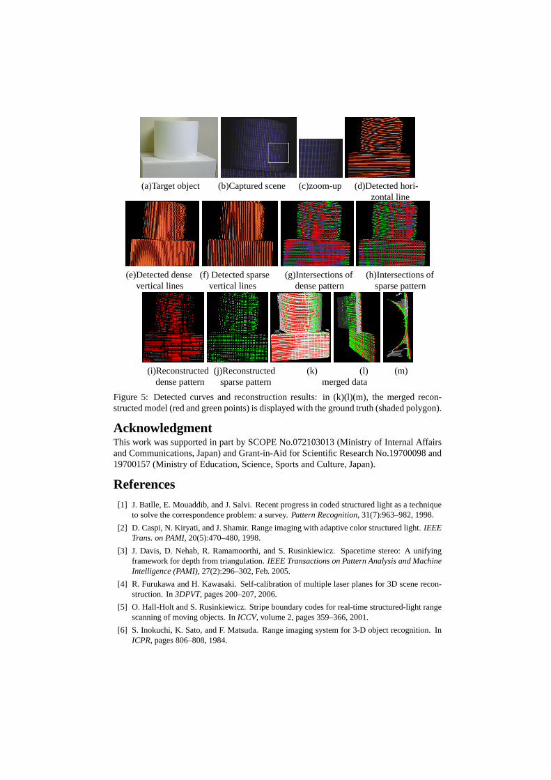
(a)Target object (b)Captured scene (c)zoom-up (d)Detected hori-zontal line
(e)Detected dense (f) Detected sparse (g)Intersections of (h)Intersections ofvertical lines vertical lines dense pattern sparse pattern
(i)Reconstructed (j)Reconstructed (k) (l) (m)dense pattern sparse pattern merged data
Figure 5: Detected curves and reconstruction results: in (k)(l)(m), the merged recon-structed model (red and green points) is displayed with the ground truth (shaded polygon).
AcknowledgmentThis work was supported in part by SCOPE No.072103013 (Ministry of Internal Affairsand Communications, Japan) and Grant-in-Aid for Scientific Research No.19700098 and19700157 (Ministry of Education, Science, Sports and Culture, Japan).
References[1] J. Batlle, E. Mouaddib, and J. Salvi. Recent progress in coded structured light as a technique
to solve the correspondence problem: a survey.Pattern Recognition, 31(7):963–982, 1998.
[2] D. Caspi, N. Kiryati, and J. Shamir. Range imaging with adaptive color structured light.IEEETrans. on PAMI, 20(5):470–480, 1998.
[3] J. Davis, D. Nehab, R. Ramamoorthi, and S. Rusinkiewicz. Spacetime stereo: A unifyingframework for depth from triangulation.IEEE Transactions on Pattern Analysis and MachineIntelligence (PAMI), 27(2):296–302, Feb. 2005.
[4] R. Furukawa and H. Kawasaki. Self-calibration of multiple laser planes for 3D scene recon-struction. In3DPVT, pages 200–207, 2006.
[5] O. Hall-Holt and S. Rusinkiewicz. Stripe boundary codes for real-time structured-light rangescanning of moving objects. InICCV, volume 2, pages 359–366, 2001.
[6] S. Inokuchi, K. Sato, and F. Matsuda. Range imaging system for 3-D object recognition. InICPR, pages 806–808, 1984.

(a) (b) (c)
(d) (e) (f)Figure 6: Reconstruction of fast rotating fan: (a) target object, (b) the captured frameswith shutter speed 1/1000, (c) the captured frames with shutter speed 1/2550, and (d) to(f) reconstructed shapes.
[7] C. Je, S. W. Lee, and R.-H. Park. High-contrast color-stripe pattern for rapid structured-lightrange imaging. InECCV, volume 1, pages 95–107, 2004.
[8] H. Kawasaki, R. Furukawa, , R. Sagawa, and Y. Yagi. Dynamic scene shape reconstructionusing a single structured light pattern. InCVPR, pages –, 2008.
[9] T. P. Koninckx and L. V. Gool. Real-time range acquisition by adaptive structured light.IEEETrans. on PAMI, 28(3):432–445, March 2006.
[10] T. P. Koninckx, T. Jaeggli, and L. V. Gool. Adaptive scanning for online 3d model acquisition.In Sensor3D04, pages 32–32, 2004.
[11] J. Pan, P. S. Huang, and F.-P. Chiang. Color-coded binary fringe projection technique for 3-dshape measurement.Optical Engineering, 44(2):23606–23615, 2005.
[12] J. Salvi, J. Batlle, and E. M. Mouaddib. A robust-coded pattern projection for dynamic 3Dscene measurement.Pattern Recognition, 19(11):1055–1065, 1998.
[13] K. Sato and S. Inokuchi. Range-imaging system utilizing nematic liquid crystal mask. InProc. of FirstICCV, pages 657–661, 1987.
[14] M. Young, E. Beeson, J. Davis, S. Rusinkiewicz, and R. Ramamoorthi. Viewpoint-codedstructured light. InIEEE Computer Society Conference on Computer Vision and PatternRecognition (CVPR), June 2007.
[15] L. Zhang, B. Curless, and S. M. Seitz. Spacetime stereo: Shape recovery for dynamic scenes.In IEEE Computer Society Conference on Computer Vision and Pattern Recognition, pages367–374, June 2003.
[16] L. Zhang, N. Snavely, B. Curless, and S. M. Seitz. Spacetime faces: High-resolution capturefor modeling and animation. InACM Annual Conference on Computer Graphics, pages 548–558, August 2004.