3B.19 Pavement Word and Symbol Section 3B.20 Pavement Word ...
27
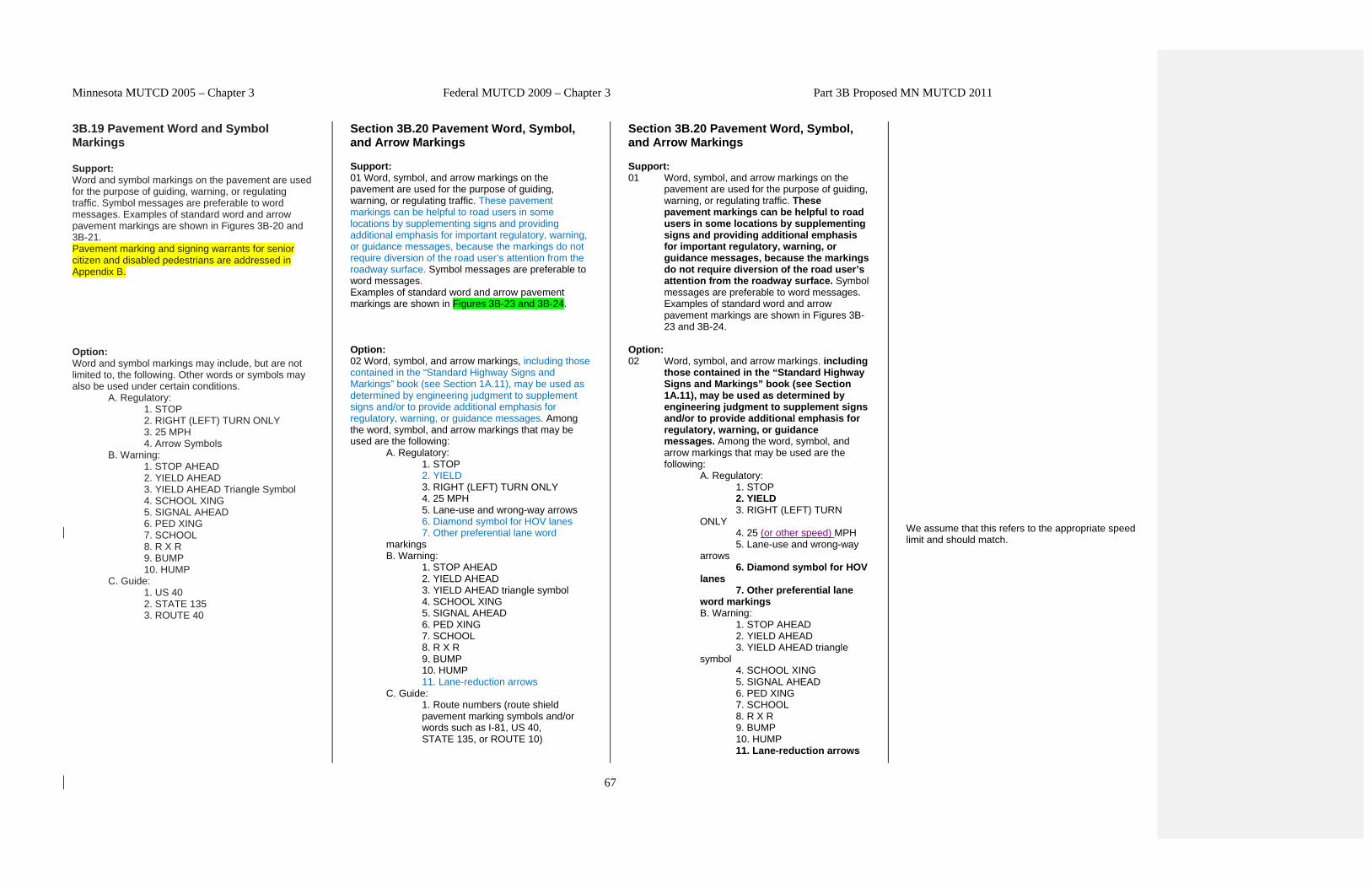
Minnesota MUTCD 2005 – Chapter 3 Federal MUTCD 2009 – Chapter 3 Part 3B Proposed MN MUTCD 2011 67 3B.19 Pavement Word and Symbol Markings Support: Word and symbol markings on the pavement are used for the purpose of guiding, warning, or regulating traffic. Symbol messages are preferable to word messages. Examples of standard word and arrow pavement markings are shown in Figures 3B-20 and 3B-21. Pavement marking and signing warrants for senior citizen and disabled pedestrians are addressed in Appendix B. Option: Word and symbol markings may include, but are not limited to, the following. Other words or symbols may also be used under certain conditions. A. Regulatory: 1. STOP 2. RIGHT (LEFT) TURN ONLY 3. 25 MPH 4. Arrow Symbols B. Warning: 1. STOP AHEAD 2. YIELD AHEAD 3. YIELD AHEAD Triangle Symbol 4. SCHOOL XING 5. SIGNAL AHEAD 6. PED XING 7. SCHOOL 8. R X R 9. BUMP 10. HUMP C. Guide: 1. US 40 2. STATE 135 3. ROUTE 40 Section 3B.20 Pavement Word, Symbol, and Arrow Markings Support: 01 Word, symbol, and arrow markings on the pavement are used for the purpose of guiding, warning, or regulating traffic. These pavement markings can be helpful to road users in some locations by supplementing signs and providing additional emphasis for important regulatory, warning, or guidance messages, because the markings do not require diversion of the road user’s attention from the roadway surface. Symbol messages are preferable to word messages. Examples of standard word and arrow pavement markings are shown in Figures 3B-23 and 3B-24. Option: 02 Word, symbol, and arrow markings, including those contained in the “Standard Highway Signs and Markings” book (see Section 1A.11), may be used as determined by engineering judgment to supplement signs and/or to provide additional emphasis for regulatory, warning, or guidance messages. Among the word, symbol, and arrow markings that may be used are the following: A. Regulatory: 1. STOP 2. YIELD 3. RIGHT (LEFT) TURN ONLY 4. 25 MPH 5. Lane-use and wrong-way arrows 6. Diamond symbol for HOV lanes 7. Other preferential lane word markings B. Warning: 1. STOP AHEAD 2. YIELD AHEAD 3. YIELD AHEAD triangle symbol 4. SCHOOL XING 5. SIGNAL AHEAD 6. PED XING 7. SCHOOL 8. R X R 9. BUMP 10. HUMP 11. Lane-reduction arrows C. Guide: 1. Route numbers (route shield pavement marking symbols and/or words such as I-81, US 40, STATE 135, or ROUTE 10) Section 3B.20 Pavement Word, Symbol, and Arrow Markings Support: 01 Word, symbol, and arrow markings on the pavement are used for the purpose of guiding, warning, or regulating traffic. These pavement markings can be helpful to road users in some locations by supplementing signs and providing additional emphasis for important regulatory, warning, or guidance messages, because the markings do not require diversion of the road user’s attention from the roadway surface. Symbol messages are preferable to word messages. Examples of standard word and arrow pavement markings are shown in Figures 3B- 23 and 3B-24. Option: 02 Word, symbol, and arrow markings, including those contained in the “Standard Highway Signs and Markings” book (see Section 1A.11), may be used as determined by engineering judgment to supplement signs and/or to provide additional emphasis for regulatory, warning, or guidance messages. Among the word, symbol, and arrow markings that may be used are the following: A. Regulatory: 1. STOP 2. YIELD 3. RIGHT (LEFT) TURN ONLY 4. 25 (or other speed) MPH 5. Lane-use and wrong-way arrows 6. Diamond symbol for HOV lanes 7. Other preferential lane word markings B. Warning: 1. STOP AHEAD 2. YIELD AHEAD 3. YIELD AHEAD triangle symbol 4. SCHOOL XING 5. SIGNAL AHEAD 6. PED XING 7. SCHOOL 8. R X R 9. BUMP 10. HUMP 11. Lane-reduction arrows We assume that this refers to the appropriate speed limit and should match.
Transcript of 3B.19 Pavement Word and Symbol Section 3B.20 Pavement Word ...
Minnesota MUTCD 2005 – Chapter 3 Federal MUTCD 2009 – Chapter 3 Part 3B Proposed MN MUTCD 2011
67
3B.19 Pavement Word and Symbol Markings Support: Word and symbol markings on the pavement are used for the purpose of guiding, warning, or regulating traffic. Symbol messages are preferable to word messages. Examples of standard word and arrow pavement markings are shown in Figures 3B-20 and 3B-21. Pavement marking and signing warrants for senior citizen and disabled pedestrians are addressed in Appendix B. Option: Word and symbol markings may include, but are not limited to, the following. Other words or symbols may also be used under certain conditions.
A. Regulatory: 1. STOP 2. RIGHT (LEFT) TURN ONLY 3. 25 MPH 4. Arrow Symbols
B. Warning: 1. STOP AHEAD 2. YIELD AHEAD 3. YIELD AHEAD Triangle Symbol 4. SCHOOL XING 5. SIGNAL AHEAD 6. PED XING 7. SCHOOL 8. R X R 9. BUMP 10. HUMP
C. Guide: 1. US 40 2. STATE 135 3. ROUTE 40
Section 3B.20 Pavement Word, Symbol, and Arrow Markings Support: 01 Word, symbol, and arrow markings on the pavement are used for the purpose of guiding, warning, or regulating traffic. These pavement markings can be helpful to road users in some locations by supplementing signs and providing additional emphasis for important regulatory, warning, or guidance messages, because the markings do not require diversion of the road user’s attention from the roadway surface. Symbol messages are preferable to word messages. Examples of standard word and arrow pavement markings are shown in Figures 3B-23 and 3B-24. Option: 02 Word, symbol, and arrow markings, including those contained in the “Standard Highway Signs and Markings” book (see Section 1A.11), may be used as determined by engineering judgment to supplement signs and/or to provide additional emphasis for regulatory, warning, or guidance messages. Among the word, symbol, and arrow markings that may be used are the following:
A. Regulatory: 1. STOP 2. YIELD 3. RIGHT (LEFT) TURN ONLY 4. 25 MPH 5. Lane-use and wrong-way arrows 6. Diamond symbol for HOV lanes 7. Other preferential lane word
markings B. Warning:
1. STOP AHEAD 2. YIELD AHEAD 3. YIELD AHEAD triangle symbol 4. SCHOOL XING 5. SIGNAL AHEAD 6. PED XING 7. SCHOOL 8. R X R 9. BUMP 10. HUMP 11. Lane-reduction arrows
C. Guide: 1. Route numbers (route shield pavement marking symbols and/or words such as I-81, US 40, STATE 135, or ROUTE 10)
Section 3B.20 Pavement Word, Symbol, and Arrow Markings Support: 01 Word, symbol, and arrow markings on the
pavement are used for the purpose of guiding, warning, or regulating traffic. These pavement markings can be helpful to road users in some locations by supplementing signs and providing additional emphasis for important regulatory, warning, or guidance messages, because the markings do not require diversion of the road user’s attention from the roadway surface. Symbol messages are preferable to word messages. Examples of standard word and arrow pavement markings are shown in Figures 3B-23 and 3B-24.
Option: 02 Word, symbol, and arrow markings, including
those contained in the “Standard Highway Signs and Markings” book (see Section 1A.11), may be used as determined by engineering judgment to supplement signs and/or to provide additional emphasis for regulatory, warning, or guidance messages. Among the word, symbol, and arrow markings that may be used are the following:
A. Regulatory: 1. STOP 2. YIELD 3. RIGHT (LEFT) TURN
ONLY 4. 25 (or other speed) MPH 5. Lane-use and wrong-way
arrows 6. Diamond symbol for HOV
lanes 7. Other preferential lane
word markings B. Warning:
1. STOP AHEAD 2. YIELD AHEAD 3. YIELD AHEAD triangle
symbol 4. SCHOOL XING 5. SIGNAL AHEAD 6. PED XING 7. SCHOOL 8. R X R 9. BUMP 10. HUMP 11. Lane-reduction arrows
We assume that this refers to the appropriate speed limit and should match.

Minnesota MUTCD 2005 – Chapter 3 Federal MUTCD 2009 – Chapter 3 Part 3B Proposed MN MUTCD 2011
68
Standard: Word and symbol markings shall be white, except as otherwise noted in this Section. Letters and numerals should be 2.5 m (8 ft) or more in height. Word and symbol markings should not exceed three lines of information. If a pavement marking word message consists of more than one line of information, it should read in the direction of travel. The first word of the message should be nearest to the road user. Except for the two opposing arrows of a two-way left turn lane marking (see Figure 3B-7), the longitudinal space between word or symbol message markings, including arrow markings, should be at least four times the height of the characters for low-speed roads, but not more than ten times the height of the characters under any conditions. Moved to Guidance Compliance Date: December 22, 2008 The number of different word and symbol markings used should be minimized to provide effective guidance and avoid misunderstanding. Except as noted in the Option below, pavement word and symbol markings should be no more than one lane in width.
2. Cardinal directions (NORTH, SOUTH, EAST, or WEST) 3. TO 4. Destination names or abbreviations thereof
Standard: 03 Word, symbol, and arrow markings shall be white, except as otherwise provided in this Section. 04 Pavement marking letters, numerals, symbols, and arrows shall be installed in accordance with the design details in the Pavement Markings chapter of the “Standard Highway Signs and Markings” book (see Section 1A.11). Guidance: 05 Letters and numerals should be 6 feet or more in height. 06 Word and symbol markings should not exceed three lines of information. 07 If a pavement marking word message consists of more than one line of information, it should read in the direction of travel. The first word of the message should be nearest to the road user. 08 Except for the two opposing arrows of a two-way left-turn lane marking (see Figure 3B-7), the longitudinal space between word or symbol message markings, including arrow markings, should be at least four times the height of the characters for low-speed roads, but not more than ten times the height of the characters under any conditions. 09 The number of different word and symbol markings used should be minimized to provide effective guidance and avoid misunderstanding. 10 Except for the SCHOOL word marking (see Section 7C.03), pavement word, symbol, and arrow markings should be no more than one lane in width.
12. 25 (or other speed) MPH C. Guide:
1. Route numbers (route shield pavement marking symbols and/or words such as I-81, US 40, STATE 135, or ROUTE 10) 2. Cardinal directions (NORTH, SOUTH, EAST, or WEST) 3. TO 4. Destination names or abbreviations thereof
Standard: 03 Word, symbol, and arrow markings shall be
white, except as otherwise provided in this Section.
04 Pavement marking letters, numerals,
symbols, and arrows shall be installed in accordance with the design details in the Pavement Markings chapter of the “Standard Highway Signs and Markings” book (see Section 1A.11).
Guidance 05 Letters and numerals should be 6 feet or more in height. 06 Word and symbol markings should not exceed
three lines of information. 07 If a pavement marking word message consists
of more than one line of information, it should read in the direction of travel. The first word of the message should be nearest to the road user.
08 Except for the two opposing arrows of a two-
way left-turn lane marking (see Figure 3B-7), the longitudinal space between word or symbol message markings, including arrow markings, should be at least four times the height of the characters for low-speed roads, but not more than ten times the height of the characters under any conditions.
09 The number of different word and symbol
markings used should be minimized to provide effective guidance and avoid misunderstanding.
10 Except for the SCHOOL word marking (see
Section 7C.03), pavement word, symbol, and
Added to provide the opportunity to use for additional emphasis for an advisory speed. Use Mn/DOT’s standard sign manual instead? No, the Standard Signs Manual doesn’t have pavement markings with all the dimensions. Use new 6 ft or old 8 ft? Stick with 6 as this affords more flexibility for locals. In addition, as the Standard Highway Signs and Markings document is Federal – we would likely need to publish a different document with many dimensions based on the 8 feet.

Minnesota MUTCD 2005 – Chapter 3 Federal MUTCD 2009 – Chapter 3 Part 3B Proposed MN MUTCD 2011
69
Option: The SCHOOL word marking may extend to the width of two approach lanes (see Section 7C.6). Moved to Guidance Guidance: When the SCHOOL word marking is extended to the width of two approach lanes, the characters should be 3 m (10 ft) or more in height (see Section 7C.6). Pavement word and symbol markings should be proportionally scaled to fit within the width of the facility upon which they are applied. Option: On narrow, low-speed shared-use paths, the pavement words and symbols may be smaller than suggested, but to the relative scale. Standard: Except at the ends of aisles in parking lots, the word STOP shall not be used on the pavement unless accompanied by a stop line (see Section 3B.16) and STOP sign (see Section 2B.4). At the ends of aisles in parking lots, the word STOP shall not be used on the pavement unless accompanied by a stop line. The word STOP shall not be placed on the pavement in advance of a stop line, unless every vehicle is required to stop at all times. Option: A yield-ahead triangle symbol or YIELD AHEAD word pavement marking may be used on approaches to intersections where the approaching traffic will encounter a YIELD sign at the intersection (see Figure 3B-25). Standard: The yield-ahead triangle symbol or YIELD AHEAD word pavement marking shall not be used unless a YIELD sign (see Section 2B.8) is in place at the intersection. The yield-ahead symbol marking shall be as shown in Figure 3B-25.
11 Pavement word, symbol, and arrow markings should be proportionally scaled to fit within the width of the facility upon which they are applied. Option: 12 On narrow, low-speed shared-use paths, the pavement words, symbols, and arrows may be smaller than suggested, but to the relative scale. 13 Pavement markings simulating Interstate, U.S., State, and other official highway route shield signs (see Figure 2D-3) with appropriate route numbers, but elongated for proper proportioning when viewed as a marking, may be used to guide road users to their destinations (see Figure 3B-25). Standard: 14 Except at the ends of aisles in parking lots, the word STOP shall not be used on the pavement unless accompanied by a stop line (see Section 3B.16) and STOP sign (see Section 2B.05). At the ends of aisles in parking lots, the word STOP shall not be used on the pavement unless accompanied by a stop line. 15 The word STOP shall not be placed on the pavement in advance of a stop line, unless every vehicle is required to stop at all times. Option: 16 A yield-ahead triangle symbol (see Figure 3B-26) or YIELD AHEAD word pavement marking may be used on approaches to intersections where the approaching traffic will encounter a YIELD sign at the intersection. Standard: 17 The yield-ahead triangle symbol or YIELD AHEAD word pavement marking shall not be used unless a YIELD sign (see Section 2B.08) is in place at the intersection. The yield-ahead symbol marking shall be as shown in Figure 3B-26.
arrow markings should be no more than one lane in width.
11 Pavement word, symbol, and arrow markings
should be proportionally scaled to fit within the width of the facility upon which they are applied.
Option: 12 On narrow, low-speed shared-use paths, the
pavement words, symbols, and arrows may be smaller than suggested, but to the relative scale.
13 Pavement markings simulating Interstate,
U.S., State, and other official highway route shield signs (see Figure 2D-3) with appropriate route numbers, but elongated for proper proportioning when viewed as a marking, may be used to guide road users to their destinations (see Figure 3B-25).
Standard: 14 Except at the ends of aisles in parking lots, the
word STOP shall not be used on the pavement unless accompanied by a stop line (see Section 3B.16) and STOP sign (see Section 2B.05). At the ends of aisles in parking lots, the word STOP shall not be used on the pavement unless accompanied by a stop line.
15 The word STOP shall not be placed on the
pavement in advance of a stop line, unless every vehicle is required to stop at all times.
Option: 16 A yield-ahead triangle symbol (see Figure 3B-
26) or YIELD AHEAD word pavement marking may be used on approaches to intersections where the approaching traffic will encounter a YIELD sign at the intersection.
Standard: 17 The yield-ahead triangle symbol or YIELD
AHEAD word pavement marking shall not be used unless a YIELD sign (see Section 2B.08) is in place at the intersection. The yield-ahead symbol marking shall be as shown in Figure 3B-26.
Keep MN Language? The Task Force said no.

Minnesota MUTCD 2005 – Chapter 3 Federal MUTCD 2009 – Chapter 3 Part 3B Proposed MN MUTCD 2011
70
Option The International Symbol of Accessibility parking space markings may be placed in each parking space designated for use by persons with disabilities. Moved to Guidance. A blue background with white border may supplement the wheelchair symbol as shown in Figure 3B-19. Support: Lane-use arrow markings are often used to provide guidance in turn bays (see Figure 3B-22), where turns may or may not be mandatory, and in two-way left-turn lanes (see Figure 3B-7).
Guidance: 18 The International Symbol of Accessibility parking space marking (see Figure 3B-22) should be placed in each parking space designated for use by persons with disabilities. Option: 19 A blue background with white border may supplement the wheelchair symbol as shown in Figure 3B-22. Support: 20 Lane-use arrow markings (see Figure 3B-24) are used to indicate the mandatory or permissible movements in certain lanes (see Figure 3B-27) and in two-way left-turn lanes (see Figure 3B-7). Guidance: 21 Lane-use arrow markings (see Figure 3B-24) should be used in lanes designated for the exclusive use of a turning movement, including turn bays, except where engineering judgment determines that physical conditions or other markings (such as a dotted extension of the lane line through the taper into the turn bay) clearly discourage unintentional use of a turn bay by through vehicles. Lane-use arrow markings should also be used in lanes from which movements are allowed that are contrary to the normal rules of the road (see Drawing B of Figure 3B-13). When used in turn lanes, at least two arrows should be used, one at or near the upstream end of the full-width turn lane and one an appropriate distance upstream from the stop line or intersection (see Drawing A of Figure 3B-11). Option: 22 An additional arrow or arrows may be used in a turn lane. When arrows are used for a short turn lane, the second (downstream) arrow may be omitted based on engineering judgment. Guidance: 23 Where opposing offset channelized left-turn lanes exist, lane-use arrow markings should be placed near the downstream terminus of the offset left-turn lanes to reduce wrong-way movements (see Figure 2B-17).
Guidance: 18 The International Symbol of Accessibility
parking space marking (see Figure 3B-22) should be placed in each parking space designated for use by persons with disabilities.
Option: 19 A blue background with white border may
supplement the wheelchair symbol as shown in Figure 3B-22.
Support: 20 Lane-use arrow markings (see Figure 3B-24)
are used to indicate the mandatory or permissible movements in certain lanes (see Figure 3B-27) and in two-way left-turn lanes (see Figure 3B-7).
Guidance: 21 Lane-use arrow markings (see Figure 3B-
24) should be used in lanes designated for the exclusive use of a turning movement, including turn bays, except where engineering judgment determines that physical conditions or other markings (such as a dotted extension of the lane line through the taper into the turn bay) clearly discourage unintentional use of a turn bay by through vehicles. Lane-use arrow markings should also be used in lanes from which movements are allowed that are contrary to the normal rules of the road (see Drawing B of Figure 3B-13). When used in turn lanes, at least two arrows should be used, one at or near the upstream end of the full-width turn lane and one an appropriate distance upstream from the stop line or intersection (see Drawing A of Figure 3B-11).
Option: 22 An additional arrow or arrows may be used
in a turn lane. When arrows are used for a short turn lane, the second (downstream) arrow may be omitted based on engineering judgment.
Guidance: 23 Where opposing offset channelized left-
turn lanes exist, lane-use arrow markings should be placed near the downstream terminus of the offset left-turn lanes to reduce wrong-way movements (see Figure 2B-17).
This could have major cost implications. Full committee should discuss. Question for Will – are there any studies that back this Guidance? There may be an armed revolt by our Greater MN districts. This possibility may make it more palatable. End of Meeting 4/25/11.

Minnesota MUTCD 2005 – Chapter 3 Federal MUTCD 2009 – Chapter 3 Part 3B Proposed MN MUTCD 2011
71
Standard: Where through traffic lanes approaching an intersection become mandatory turn lanes, lane-use arrow markings (see Figure 3B-21) shall be used and shall be accompanied by standard signs. Standard: Where through lanes become mandatory turn lanes, signs or markings should be repeated as necessary to prevent entrapment and to help the road user select the appropriate lane in advance of reaching a queue of waiting vehicles. Moved to Guidance
Support: 24 An arrow at the downstream end of a turn lane can help to prevent wrong way movements. Standard: 25 Where through lanes approaching an intersection become mandatory turn lanes, lane-use arrow markings (see Figure 3B-24) shall be used and shall be accompanied by standard signs. Guidance: 26 Where through lanes approaching an intersection become mandatory turn lanes, ONLY word markings (see Figure 3B-23) should be used in addition to the required lane-use arrow markings and signs (see Sections 2B.19 and 2B.20). These markings and signs should be placed well in advance of the turn and should be repeated as necessary to prevent entrapment and to help the road user select the appropriate lane in advance of reaching a queue of waiting vehicles (see Drawing A of Figure 3B-11). Option: 27 On freeways or expressways where a through lane becomes a mandatory exit lane, lane-use arrow markings may be used on the approach to the exit in the dropped lane and in an adjacent optional through-or-exit lane if one exists. Guidance: 28 A two-way left-turn lane-use arrow pavement marking, with opposing arrows spaced as shown in Figure 3B-7, should be used at or just downstream from the beginning of a two-way left-turn lane. Option: 29 Additional two-way left-turn lane-use arrow markings may be used at other locations along a two-way left-turn lane where engineering judgment determines that such additional markings are needed to emphasize the proper use of the lane.
Support: 24 An arrow at the downstream end of a turn
lane can help to prevent wrong way movements.
Standard: 25 Where through lanes approaching an
intersection become mandatory turn lanes, lane-use arrow markings (see Figure 3B-24) shall be used and shall be accompanied by standard signs.
Guidance 26 Where through lanes approaching an
intersection become mandatory turn lanes, ONLY word markings (see Figure 3B-23) should be used in addition to the required lane-use arrow markings and signs (see Sections 2B.19 and 2B.20). These markings and signs should be placed well in advance of the turn and should be repeated as necessary to prevent entrapment and to help the road user select the appropriate lane in advance of reaching a queue of waiting vehicles (see Drawing A of Figure 3B-11).
Option: 27 On freeways or expressways where a
through lane becomes a mandatory exit lane, lane-use arrow markings may be used on the approach to the exit in the dropped lane and in an adjacent optional through-or-exit lane if one exists.
Guidance: 28 A two-way left-turn lane-use arrow
pavement marking, with opposing arrows spaced as shown in Figure 3B-7, should be used at or just downstream from the beginning of a two-way left-turn lane.
Option: 29 Additional two-way left-turn lane-use arrow
markings may be used at other locations along a two-way left-turn lane where engineering judgment determines that such additional markings are needed to emphasize the proper use of the lane.
Start of Pavement Marking Task Force – 4/27/11 Ken Johnson Ted Ulven Jim Rosenow Joe Gustafson Sheila Johnson Jim Miles

Minnesota MUTCD 2005 – Chapter 3 Federal MUTCD 2009 – Chapter 3 Part 3B Proposed MN MUTCD 2011
72
Standard: Lane use, lane reduction, and wrong-way arrow markings shall be designed as shown in Figure 3B-21. Option: Lane-use arrow markings (see Figure 3B-21) may be used to convey either guidance or mandatory messages. The ONLY word marking (see Figure 3B-20) may be used to supplement lane-use arrow markings (see Figure 3B-22). In situations where a lane reduction transition occurs, the lane reduction arrow markings shown in Figure 3B-21 may be used. Guidance: Where crossroad channelization or ramp geometrics do not make wrong-way movements difficult, a lane-use arrow should be placed in each lane of an exit ramp near the crossroad terminal where it will be clearly visible to a potential wrong-way road user (see Figure 3B-23).
Standard: 30 A single-direction lane-use arrow shall not be used in a lane bordered on both sides by yellow two-way left-turn lane longitudinal markings. 31 Lane-use, lane-reduction, and wrong-way arrow markings shall be designed as shown in Figure 3B-24 and in the “Standard Highway Signs and Markings” book (see Section 1A.11). Option: 32 The ONLY word marking (see Figure 3B-23) may be used to supplement the lane-use arrow markings in lanes that are designated for the exclusive use of a single movement (see Figure 3B-27) or to supplement a preferential lane word or symbol marking (see Section 3D.01). Standard: 33 The ONLY word marking shall not be used in a lane that is shared by more than one movement. Guidance: 34 Where a lane-reduction transition occurs on a roadway with a speed limit of 45 mph or more, the lane-reduction arrow markings shown in Drawing f in Figure 3B-24 should be used (see Figure 3B-14). Except for acceleration lanes, where a lane-reduction transition occurs on a roadway with a speed limit of less than 45 mph, the lane-reduction arrow markings shown in Drawing f in Figure 3B-24 should be used if determined to be appropriate based on engineering judgment. Option: 35 Lane-reduction arrow markings may be used in long acceleration lanes based on engineering judgment. Guidance: 36 Where crossroad channelization or ramp geometrics do not make wrong-way movements difficult, the appropriate lane-use arrow should be placed in each lane of an exit ramp near the crossroad terminal where it will be clearly visible to a potential wrong-way road user (see Figure 2B-18).
Standard: 30 A single-direction lane-use arrow shall not
be used in a lane bordered on both sides by yellow two-way left-turn lane longitudinal markings.
31 Lane-use, lane-reduction, and wrong-way
arrow markings shall be designed as shown in Figure 3B-24 and in the “Standard Highway Signs and Markings” book (see Section 1A.11).
Option: 32 The ONLY word marking (see Figure 3B-23)
may be used to supplement the lane-use arrow markings in lanes that are designated for the exclusive use of a single movement (see Figure 3B-27) or to supplement a preferential lane word or symbol marking (see Section 3D.01).
Standard: 33 The ONLY word marking shall not be used
in a lane that is shared by more than one movement.
Guidance: 34 Where a lane-reduction transition occurs
on a roadway with a speed limit of 45 mph or more, the lane-reduction arrow markings shown in Drawing F in Figure 3B-24 should be used (see Figure 3B-14). Except for acceleration lanes, where a lane-reduction transition occurs on a roadway with a speed limit of less than 45 mph, the lane-reduction arrow markings shown in Drawing F in Figure 3B-24 should be used if determined to be appropriate based on engineering judgment.
Option: 35 Lane-reduction arrow markings may be used
in long acceleration lanes based on engineering judgment.
Guidance: 36 Where crossroad channelization or ramp
geometrics do not make wrong-way movements difficult, the appropriate lane-use arrow should be placed in each lane of an exit ramp near the crossroad terminal where it will be clearly visible to a potential wrong-way road user (see Figure 2B-18).
Does this affect our typical two-way left-turn lane marking? TEM Fig 7.3 This is a change in MN typical practice. We are concerned with this standard, there have been situations where applying both arrows creates driver confusion. This seems to be contradictory of paragraph 2 of Section 3B.09 and figure 3B-14. Request for interpretation – do we have to put in lane reduction markings for all lane-reduction situations.

Minnesota MUTCD 2005 – Chapter 3 Federal MUTCD 2009 – Chapter 3 Part 3B Proposed MN MUTCD 2011
73
Option: The wrong-way arrow markings shown in Figure 3B-21 may be placed near the downstream terminus of a ramp as shown in Figures 3B-23 and 3B-24 to indicate the correct direction of traffic flow and to discourage drivers from traveling in the wrong direction.
Option: 37 The wrong-way arrow markings shown in Drawing D in Figure 3B-24 may be placed near the downstream terminus of a ramp as shown in Figures 2B-18 and 2B-19, or at other locations where lane-use arrows are not appropriate, to indicate the correct direction of traffic flow and to discourage drivers from traveling in the wrong direction.
Option: 37 The wrong-way arrow markings shown in
Drawing D in Figure 3B-24 may be placed near the downstream terminus of a ramp as shown in Figures 2B-18 and 2B-19, or at other locations where lane-use arrows are not appropriate, to indicate the correct direction of traffic flow and to discourage drivers from traveling in the wrong direction.

Minnesota MUTCD 2005 – Chapter 3 Federal MUTCD 2009 – Chapter 3 Part 3B Proposed MN MUTCD 2011
74
3B-19 ->3B-22 3B-20 ->3B-23

Minnesota MUTCD 2005 – Chapter 3 Federal MUTCD 2009 – Chapter 3 Part 3B Proposed MN MUTCD 2011
75
3B-21 ->3B-25 3B-26 New

Minnesota MUTCD 2005 – Chapter 3 Federal MUTCD 2009 – Chapter 3 Part 3B Proposed MN MUTCD 2011
76
3B-25 ->3B-26

Minnesota MUTCD 2005 – Chapter 3 Federal MUTCD 2009 – Chapter 3 Part 3B Proposed MN MUTCD 2011
77

Minnesota MUTCD 2005 – Chapter 3 Federal MUTCD 2009 – Chapter 3 Part 3B Proposed MN MUTCD 2011
78
Keep? No, refer them to 2B-18.

Minnesota MUTCD 2005 – Chapter 3 Federal MUTCD 2009 – Chapter 3 Part 3B Proposed MN MUTCD 2011
79
Keep? No, refer them to 2B-19
Minnesota MUTCD 2005 – Chapter 3 Federal MUTCD 2009 – Chapter 3 Part 3B Proposed MN MUTCD 2011
80
B.20 Speed Measurement Markings Support: A speed measurement marking is a transverse marking placed on the roadway to assist the enforcement of speed regulations. Standard: Speed measurement markings, if used, shall be white, and shall not be greater than 600 mm (24 in) in width. Option: Speed measurement markings may extend 600 mm (24 in) on either side of the centerline or 600 mm (24 in) on either side of edge line markings at 0.4 km (1/4 mi) intervals over a 1.6 km (1 mi) length of roadway. When paved shoulders of sufficient width are available, the speed measurements markings may be placed entirely on these shoulders. Advisory signs may be used in conjunction with these markings (see Figure 3B-10).
Section 3B.21 Speed Measurement Markings Support: 01 A speed measurement marking is a transverse marking placed on the roadway to assist the enforcement of speed regulations. Standard: 02 Speed measurement markings, if used, shall be white, and shall not be greater than 24 inches in width. Option: 03 Speed measurement markings may extend 24 inches on either side of the center line or 24 inches on either side of edge line markings at 1/4-mile intervals over a 1-mile length of roadway. When paved shoulders of sufficient width are available, the speed measurement markings may be placed entirely on these shoulders (see Drawing A of Figure 3B-10). Advisory signs may be used in conjunction with these markings.
Section 3B.21 Speed Measurement Markings Support: 01 A speed measurement marking is a transverse
marking placed on the roadway to assist the enforcement of speed regulations.
Standard: 02 Speed measurement markings, if used, shall
be white, and shall not be greater than 24 inches in width.
Option: 03 Speed measurement markings may extend 24
inches on either side of the center line or 24 inches on either side of edge line markings at 1/4-mile intervals over a 1-mile length of roadway. When paved shoulders of sufficient width are available, the speed measurement markings may be placed entirely on these shoulders (see Drawing A of Figure 3B-10). Advisory signs may be used in conjunction with these markings.

Minnesota MUTCD 2005 – Chapter 3 Federal MUTCD 2009 – Chapter 3 Part 3B Proposed MN MUTCD 2011
81
No Equivalent Section Section 3B.22 Speed Reduction Markings Support: 01 Speed reduction markings (see Figure 3B-28) are transverse markings that are placed on the roadway within a lane (along both edges of the lane) in a pattern of progressively reduced spacing to give drivers the impression that their speed is increasing. These markings might be placed in advance of an unexpectedly severe horizontal or vertical curve or other roadway feature where drivers need to decelerate prior to reaching the feature and where the desired reduction in speeds has not been achieved by the installation of warning signs and/or other traffic control devices. Guidance: 02 If used, speed reduction markings should be reserved for unexpected curves and should not be used on long tangent sections of roadway or in areas frequented mainly by local or familiar drivers, (e.g., school zones). If used, speed reduction markings should supplement the appropriate warning signs and other traffic control devices and should not substitute for these devices. Standard: 03 If used, speed reduction markings shall be a series of white transverse lines on both sides of the lane that are perpendicular to the center line, edge line, or lane line. The longitudinal spacing between the markings shall be progressively reduced from the upstream to the downstream end of the marked portion of the lane. Guidance: 04 Speed reduction markings should not be greater than 12 inches in width, and should not extend more than 18 inches into the lane. Standard: 05 Speed reduction markings shall not be used in lanes that do not have a longitudinal line (center line, edge line, or lane line) on both sides of the lane.
Section 3B.22 Speed Reduction Markings Support: 01 Speed reduction markings (see Figure 3B-
28) are transverse markings that are placed on the roadway within a lane (along both edges of the lane) in a pattern of progressively reduced spacing to give drivers the impression that their speed is increasing. These markings might be placed in advance of an unexpectedly severe horizontal or vertical curve or other roadway feature where drivers need to decelerate prior to reaching the feature and where the desired reduction in speeds has not been achieved by the installation of warning signs and/or other traffic control devices.
Guidance: 02 If used, speed reduction markings should
be reserved for unexpected curves and should not be used on long tangent sections of roadway or in areas frequented mainly by local or familiar drivers, (e.g., school zones). If used, speed reduction markings should supplement the appropriate warning signs and other traffic control devices and should not substitute for these devices.
Standard: 03 If used, speed reduction markings shall be
a series of white transverse lines on both sides of the lane that are perpendicular to the center line, edge line, or lane line. The longitudinal spacing between the markings shall be progressively reduced from the upstream to the downstream end of the marked portion of the lane.
Guidance: 04 Speed reduction markings should not be
greater than 12 inches in width, and should not extend more than 18 inches into the lane.
Standard: 05 Speed reduction markings shall not be
used in lanes that do not have a longitudinal line (center line, edge line, or lane line) on both sides of the lane.
Are we ok with the widths?

Minnesota MUTCD 2005 – Chapter 3 Federal MUTCD 2009 – Chapter 3 Part 3B Proposed MN MUTCD 2011
82

Minnesota MUTCD 2005 – Chapter 3 Federal MUTCD 2009 – Chapter 3 Part 3B Proposed MN MUTCD 2011
83
3B.21 Curb Markings Support: Curb markings are most often used to indicate parking regulations or to delineate the curb. Standard: Signs shall be used with curb markings in those areas where curb markings are frequently obliterated by snow and ice accumulation unless the no parking zone is controlled by statute or local ordinance. Where curbs are marked, the colors shall conform to the general principles of markings (see Section 3A.4). Guidance: Except as noted in the Option, when curb markings are used without signs to convey parking regulations, a legible word marking regarding the regulation (such as "No Parking" or "No Standing") should be placed on the curb. Option: Curb markings without word markings or signs may be used to convey a general prohibition by statute of parking within a specified distance of a STOP sign, driveway, fire hydrant, or crosswalk. Option: Local highway agencies may prescribe special colors for curb markings to supplement standard signs for parking regulation. Guidance: Retroreflective solid yellow markings should be placed on the noses of raised medians and curbs of islands that are located in the line of traffic flow where the curb serves to channel traffic to the right of the obstruction. Retroreflective solid white markings should be used when traffic may pass on either side of the island.
Section 3B.23 Curb Markings Support: 01 Curb markings are most often used to indicate parking regulations or to delineate the curb. Standard: 02 Where curbs are marked to convey parking regulations in areas where curb markings are frequently obscured by snow and ice accumulation, signs shall be used with the curb markings except as provided in Paragraph 4. Guidance: 03 Except as provided in Paragraph 4, when curb markings are used without signs to convey parking regulations, a legible word marking regarding the regulation (such as “No Parking” or “No Standing”) should be placed on the curb. Option: 04 Curb markings without word markings or signs may be used to convey a general prohibition by statute of parking within a specified distance of a STOP sign, YIELD sign, driveway, fire hydrant, or crosswalk. 05 Local highway agencies may prescribe special colors for curb markings to supplement standard signs for parking regulation. Support: 06 Since yellow and white curb markings are frequently used for curb delineation and visibility, it is advisable to establish parking regulations through the installation of standard signs (see Sections 2B.46 through 2B.48). Standard: 07 Where curbs are marked for delineation or visibility purposes, the colors shall comply with the general principles of markings (see Section 3A.05). Guidance: 08 Retroreflective solid yellow markings should be placed on the approach ends of raised medians and curbs of islands that are located in the line of traffic flow where the curb serves to channel traffic to the right of the obstruction. 09 Retroreflective solid white markings should be used when traffic is permitted to pass on either side of the island.
Section 3B.23 Curb Markings Support: 01 Curb markings are most often used to indicate
parking regulations or to delineate the curb. Standard: 02 Where curbs are marked to convey parking
regulations in areas where curb markings are frequently obscured by snow and ice accumulation, signs shall be used with the curb markings except as provided in Paragraph 4.
Guidance: 03 Except as provided in Paragraph 4, when
curb markings are used without signs to convey parking regulations, a legible word marking regarding the regulation (such as “No Parking” or “No Standing”) should be placed on the curb.
Option: 04 Curb markings without word markings or signs
may be used to convey a general prohibition by statute or local ordinance of parking within a specified distance of a stop sign, YIELD sign, driveway, fire hydrant, or crosswalk.
05 Local highway agencies may prescribe special
colors for curb markings to supplement standard signs for parking regulation.
Support: 06 Since yellow and white curb markings are
frequently used for curb delineation and visibility, it is advisable to establish parking regulations through the installation of standard signs (see Sections 2B.46 through 2B.48).
Standard: 07 Where curbs are marked for delineation or
visibility purposes, the colors shall comply with the general principles of markings (see Section 3A.05).
Guidance: 08 Retroreflective solid yellow markings should
be placed on the approach ends of raised medians and curbs of islands that are located in the line of traffic flow where the curb serves to channel traffic to the right of the obstruction.
09 Retroreflective solid white markings should be
used when traffic is permitted to pass on either side of the island.
This will allow the language in the previous MnMUTCD including local ordinances. The Task Force felt this was appropriate.

Minnesota MUTCD 2005 – Chapter 3 Federal MUTCD 2009 – Chapter 3 Part 3B Proposed MN MUTCD 2011
84
Support: Since yellow and white curb markings are frequently used for curb delineation and visibility, it is advisable to establish parking regulations through the installation of standard signs (see Sections 2B.39 through 2B.41). Where the curbs of the islands become parallel to the direction of traffic flow, it is not necessary to mark the curbs unless an engineering study indicates the need for this type of delineation. Curbs at openings in a continuous median island need not be marked unless an engineering study indicates the need for this type of marking.
Support: 10 Where the curbs of the islands become parallel to the direction of traffic flow, it is not necessary to mark the curbs unless an engineering study indicates the need for this type of delineation. 11 Curbs at openings in a continuous median island need not be marked unless an engineering study indicates the need for this type of marking. Option: 12 Retroreflective or internally illuminated raised pavement markers of the appropriate color may be placed on the pavement in front of the curb and/or on the top of curbed as noses of raised medians and curbs of islands, as a supplement to or substitute for retroreflective curb markings used for delineation.
Support: 10 Where the curbs of the islands become
parallel to the direction of traffic flow, it is not necessary to mark the curbs unless an engineering study indicates the need for this type of delineation.
11 Curbs at openings in a continuous median
island need not be marked unless an engineering study indicates the need for this type of marking.
Option: 12 Retroreflective or internally illuminated
raised pavement markers of the appropriate color may be placed on the pavement in front of the curb and/or on the top of curbed as noses of raised medians and curbs of islands, as a supplement to or substitute for retroreflective curb markings used for delineation.
From the list of known errors in the MUTCD (as of 4/8/2011) Section 3B.23 In Paragraph 12, the phrase “curbed as of” should be changed to “curbed noses of.”

Minnesota MUTCD 2005 – Chapter 3 Federal MUTCD 2009 – Chapter 3 Part 3B Proposed MN MUTCD 2011
85
3B.22 Preferential Lane Word and Symbol Markings
Moved to Ch 3D
See Chapter 3D See Chapter 3D

Minnesota MUTCD 2005 – Chapter 3 Federal MUTCD 2009 – Chapter 3 Part 3B Proposed MN MUTCD 2011
86
3B.23 Preferential Lane Longitudinal Markings for Motor Vehicles
Moved to Ch 3D
See Chapter 3D See Chapter 3D

Minnesota MUTCD 2005 – Chapter 3 Federal MUTCD 2009 – Chapter 3 Part 3B Proposed MN MUTCD 2011
87
3B.24 Markings for Roundabout Intersections Moved to Chapter 3C
See Chapter 3C See Chapter 3C

Minnesota MUTCD 2005 – Chapter 3 Federal MUTCD 2009 – Chapter 3 Part 3B Proposed MN MUTCD 2011
88
No Equivalent Section Section 3B.24 Chevron and Diagonal Crosshatch Markings Option: 01 Chevron and diagonal crosshatch markings may be used to discourage travel on certain paved areas, such as shoulders, gore areas, flush median areas between solid double yellow center line markings or between white channelizing lines approaching obstructions in the roadway (see Section 3B.10 and Figure 3B-15), between solid double yellow center line markings forming flush medians or channelized travel paths at intersections (see Figures 3B-2 and 3B-5), buffer spaces between preferential lanes and general-purpose lanes (see Figures 3D-2 and 3D-4), and at grade crossings (see Part 8). Standard: 02 When crosshatch markings are used in paved areas that separate traffic flows in the same general direction, they shall be white and they shall be shaped as chevron markings, with the point of each chevron facing toward approaching traffic, as shown in Figure 3B-8, Drawing A of Figure 3B-9, Figure 3B-10, and Drawing C of Figure 3B-15. 03 When crosshatch markings are used in paved areas that separate opposing directions of traffic, they shall be yellow diagonal markings that slant away from traffic in the adjacent travel lanes, as shown in Figures 3B-2 and 3B-5 and Drawings A and B of Figure 3B-15. 04 When crosshatch markings are used on paved shoulders, they shall be diagonal markings that slant away from traffic in the adjacent travel lane. The diagonal markings shall be yellow when used on the left-hand shoulders of the roadways of divided highways and on the left-hand shoulders of one-way streets or ramps. The diagonal markings shall be white when used on right-hand shoulders. Guidance: 05 The chevrons and diagonal lines used for crosshatch markings should be at least 12 inches wide for roadways having a posted or statutory speed limit of 45 mph or greater, and at least 8 inches wide for roadways having posted or statutory speed limit of less than 45 mph. The longitudinal spacing of the chevrons or diagonal lines should be determined by engineering judgment considering factors such as speeds and desired visual impacts. The chevrons and diagonal lines should form an angle of approximately 30 to 45 degrees with the longitudinal lines that they intersect.
Section 3B.24 Chevron and Diagonal Crosshatch Markings Option: 01 Chevron and diagonal crosshatch markings may be used to discourage travel on certain paved areas, such as shoulders, gore areas, flush median areas between solid double yellow center line markings or between white channelizing lines approaching obstructions in the roadway (see Section 3B.10 and Figure 3B-15), between solid double yellow center line markings forming flush medians or channelized travel paths at intersections (see Figures 3B-2 and 3B-5), buffer spaces between preferential lanes and general-purpose lanes (see Figures 3D-2 and 3D-4), and at grade crossings (see Part 8). Standard: 02 When crosshatch markings are used in paved areas that separate traffic flows in the same general direction, they shall be white and they shall be shaped as chevron markings, with the point of each chevron facing toward approaching traffic, as shown in Figure 3B-8, Drawing A of Figure 3B-9, Figure 3B-10, and Drawing C of Figure 3B-15. 03 When crosshatch markings are used in paved areas that separate opposing directions of traffic, they shall be yellow diagonal markings that slant away from traffic in the adjacent travel lanes, as shown in Figures 3B-2 and 3B-5 and Drawings A and B of Figure 3B-15. 04 When crosshatch markings are used on paved shoulders, they shall be diagonal markings that slant away from traffic in the adjacent travel lane. The diagonal markings shall be yellow when used on the left-hand shoulders of the roadways of divided highways and on the left-hand shoulders of one-way streets or ramps. The diagonal markings shall be white when used on right-hand shoulders. Guidance: 05 The chevrons and diagonal lines used for crosshatch markings should be at least 12 inches wide for roadways having a posted or statutory speed limit of 45 mph or greater, and at least 8 inches wide for roadways having posted or statutory speed limit of less than 45 mph. The longitudinal spacing of the chevrons or diagonal lines should be determined by engineering judgment considering factors such as speeds and desired visual impacts. The chevrons and diagonal lines should form an angle of approximately 30 to 45 degrees with the longitudinal lines that they intersect.
While creating the marking detail we decided on speeds less than 40mph. Detail used 24” solid chevron and 12” on low speeds Keep FHWA language
Minnesota MUTCD 2005 – Chapter 3 Federal MUTCD 2009 – Chapter 3 Part 3B Proposed MN MUTCD 2011
89
3B.25 Markings for Other Circular Intersections Moved to Ch 3C
See Chapter 3C See Chapter 3C

Minnesota MUTCD 2005 – Chapter 3 Federal MUTCD 2009 – Chapter 3 Part 3B Proposed MN MUTCD 2011
90
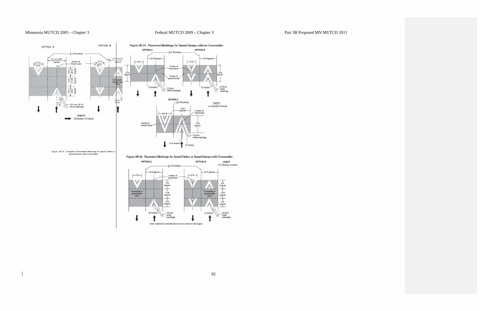
3B.26 Speed Hump Markings Standard: If used, speed hump markings shall be a series of white markings placed on a speed hump to identify its location. Options: Speed humps, except those used for crosswalks, may be marked in accordance with Figure 3B-29. The markings shown in Figure 3B-30 may be used where the speed hump also functions as a crosswalk or speed table. Moved to Standard
Section 3B.25 Speed Hump Markings Standard: 01 If speed hump markings are used, they shall be a series of white markings placed on a speed hump to identify its location. If markings are used for a speed hump that does not also function as a crosswalk or speed Table, the markings shall comply with Option A, B, or C shown in Figure 3B-29. If markings are used for a speed hump that also functions as a crosswalk or speed Table, the markings shall comply with Option A or B shown in Figure 3B-30.
Section 3B.25 Speed Hump Markings Standard: 01 If speed hump markings are used, they shall
be a series of white markings placed on a speed hump to identify its location. If markings are used for a speed hump that does not also function as a crosswalk or speed Table, the markings shall comply with Option A, B, or C shown in Figure 3B-29. If markings are used for a speed hump that also functions as a crosswalk or speed Table, the markings shall comply with Option A or B shown in Figure 3B-30.

Minnesota MUTCD 2005 – Chapter 3 Federal MUTCD 2009 – Chapter 3 Part 3B Proposed MN MUTCD 2011
91
3B.27 Advance Speed Hump Markings Option: Advance speed hump markings may be used in advance of an engineered vertical roadway deflection where added visibility is desired or where such deflection is not expected (see Figure 3B-31). Advance pavement wording such as BUMP or HUMP (see Section 3B.19) may be used on the approach to a speed hump either alone or in conjunction with advance speed hump markings. Appropriate advance warning signs may be used in conformance with Section 2C-24. Standard: If used, advance speed hump markings shall be a special white marking placed in advance of speed humps or other engineered vertical roadway deflections such as dips. Guidance: If used, advance speed hump markings should be installed in each approach lane.
Section 3B.26 Advance Speed Hump Markings Option: 01 Advance speed hump markings (see Figure 3B-31) may be used in advance of speed humps or other engineered vertical roadway deflections such as dips where added visibility is desired or where such deflection is not expected. 02 Advance pavement wording such as BUMP or HUMP (see Section 3B.20) may be used on the approach to a speed hump either alone or in conjunction with advance speed hump markings. Appropriate advance warning signs may be used in compliance with Section 2C.29. Standard: 03 If advance speed hump markings are used, they shall be a series of eight white 12-inch transverse lines that become longer and are spaced closer together as the vehicle approaches the speed hump or other deflection. If advance markings are used, they shall comply with the detailed design shown in Figure 3B-31. Guidance: 04 If used, advance speed hump markings should be installed in each approach lane.
Section 3B.26 Advance Speed Hump Markings Option: 01 Advance speed hump markings (see Figure
3B-31) may be used in advance of speed humps or other engineered vertical roadway deflections such as dips where added visibility is desired or where such deflection is not expected.
02 Advance pavement wording such as BUMP or
HUMP (see Section B.20) may be used on the approach to a speed hump either alone or in conjunction with advance speed hump markings. Appropriate advance warning signs may be used in compliance with Section 2C.29.
Standard: 03 If advance speed hump markings are used,
they shall be a series of eight white 12-inch transverse lines that become longer and are spaced closer together as the vehicle approaches the speed hump or other deflection. If advance markings are used, they shall comply with the detailed design shown in Figure 3B-31.
Guidance: 04 If used, advance speed hump markings should
be installed in each approach lane.
Minnesota MUTCD 2005 – Chapter 3 Federal MUTCD 2009 – Chapter 3 Part 3B Proposed MN MUTCD 2011
92

Minnesota MUTCD 2005 – Chapter 3 Federal MUTCD 2009 – Chapter 3 Part 3B Proposed MN MUTCD 2011
93