370_MA11-3
12
11/28/2006 - 10:30 am - 12:00 pm Room:Marcello - 4404 (MSD Campus) Making Connections with Autodesk Inventor® Professional This session will focus on using Autodesk Inventor Professional to design fluid routing systems. We will explore rigid piping, bent tubing, and flexible hose creation and documentation. MA11-3 About the Speaker: Steve Warren - D3 TECHNOLOGIES Thom Tremblay (Co-Speaker) and Steve is a Senior Solutions Engineer for D3 TECHNOLOGIES in Tulsa, OK. He has used Autodesk software since 1998 in various industries including custom sheet metal, consumer goods, custom retail fixtures, and process facilities design. In his role at D3 TECHNOLOGIES, he offers support as an Inventor Certified Expert and training as a Certified Autodesk Training Center Instructor to the Autodesk users in the Midwest region. Thom has been a solutions engineer with Autodesk's Manufacturing Solutions Division for 6 years. He has designed all kinds of products using Autodesk software including cabinets, ships, castings, electronics, and consumer goods. He began working in 3D with AutoCAD Release 9 in 1990, and has been a proponent of the advantages of 3D ever since. In his role at Autodesk, Thom uses his experience to help customers find the best combination of software and consulting for their specific needs. [email protected] Stay Connect to AU all year at www.autodesk.com/AUOnline
-
Upload
vvprasath7715 -
Category
Documents
-
view
215 -
download
1
description
inventor tube and pipe
Transcript of 370_MA11-3
11/28/2006 - 10:30 am - 12:00 pm Room:Marcello - 4404 (MSD Campus)
Making Connections with Autodesk Inventor® Professional
This session will focus on using Autodesk Inventor Professional to design fluid routing systems. We will explore rigid piping, bent tubing, and flexible hose creation and documentation.
MA11-3
About the Speaker:
Steve Warren - D3 TECHNOLOGIESThom Tremblay (Co-Speaker)and
Steve is a Senior Solutions Engineer for D3 TECHNOLOGIES in Tulsa, OK. He has used Autodesk software since 1998 in various industries including custom sheet metal, consumer goods, custom retail fixtures, and process facilities design. In his role at D3 TECHNOLOGIES, he offers support as an Inventor Certified Expert and training as a Certified Autodesk Training Center Instructor to the Autodesk users in the Midwest region.
Thom has been a solutions engineer with Autodesk's Manufacturing Solutions Division for 6 years. He has designed all kinds of products using Autodesk software including cabinets, ships, castings, electronics, and consumer goods. He began working in 3D with AutoCAD Release 9 in 1990, and has been a proponent of the advantages of 3D ever since. In his role at Autodesk, Thom uses his experience to help customers find the best combination of software and consulting for their specific [email protected]
Stay Connect to AU all year at www.autodesk.com/AUOnline

Making Connections with Autodesk Inventor® Professional
2
What is the Tube and Pipe package of Inventor Professional?
The Tube and Pipe package of Inventor Professional allows you to reduce the time spent to develop complex piping designs through the use of user defined rules for component placement and system routing. The package was designed for industrial machinery applications. It was not intended to be a process piping application.
What will we cover in this session?
1. Tube and pipe styles
Styles control the default behavior of rigid pipe, bent tubing, and flexible hose including nominal size, material, standards, rules for segment lengths and angles, and default fittings for different configurations.
2. Tube and pipe environment
In this section we will discuss how tube and pipe components interact with other parts and subassemblies within a top level assembly as well as the structure inside the tube and pipe subassembly.
3. Placing initial fittings
Placing initial fittings from the content center through the tube and pipe functions of Inventor allow additional control of thread depth and other engagement options. This also allows for connection points on the fittings to be used for the start and end points of the routes.
4. Creating routes
There are several different ways of creating a route including auto routing, manual routing, and the derived sketch method for rigid pipe and tubing. Flexible hoses use a spline based route rather than line based like rigid pipe and tubing.
5. Editing routes
To edit routes you add, remove and move nodes along the path of the route. Copying an entire route can save a lot of time instead of creating an entire new route.
6. Editing fittings and components
Replacing the default couplings and elbows is easy with Inventor Professional. You can add and/or replace fittings with custom fittings or fittings from the content center.

Making Connections with Autodesk Inventor® Professional
3
7. Documenting tube and pipe systems
Inventor Professional has templates with custom part lists specifically for tube and pipe runs. The software also gives you the ability to make flexible hose subassemblies “inseparable” in the electronic bill of materials.
Tube and pipe styles
There are three different types of styles, rigid pipe, tube, and flexible hose. In all three, styles define specification on pipe, tube, hose, fittings, and rules for segment lengths and bends. It is possible to change a style from rigid pipe to tube and vise versa, but it is not possible to change either rigid pipe or tube to flexible hose or vise versa. This is the reason that the flexible hose option is grayed out of a rigid pipe or tube style.
To create a new style, simply click the icon directly to the right of the style dropdown dialog box. Once you select this icon, it will create a new style based on the current style selection at the time you selected the icon.
The general tab contains the selection options for both route type and route direction. This tab also contains filters for both the pipe and the fittings. These filters will affect the selections that are available on both the size and fittings tabs. On the size tab, you select the nominal size of the pipe, tubing or hose. There is only one selection for size for each style, so if you wish to have multiple sizes of pipe, tube or hose, you must create another style. On the rules tab, you can specify min and max lengths of pipe or tube as well as bend radius specifications and hose round up values. The display tab controls the visual characteristics of the pipe, tube or hose. The fittings tab will allow you to select the default fittings for pipe, coupling, 45° elbow, and 90° elbow in the case of a rigid pipe type style. If a tube type style is used, you will have the option to select the default for pipe and coupling. Lastly, if a flexible hose type style is used, it will allow you to set the default for the hose and the starting and ending connections.
After determining what styles you will be using most often, it is a good idea to save these to the tube and pipe runs subassembly that is added to a standard assembly when you select to create a tube and pipe run. This procedure is significantly different than the standard procedure for other Inventor templates. Good instructions and information can be found on this in the help system under Inventor Professional -> Tube and Pipe -> Templates and Styles.

Making Connections with Autodesk Inventor® Professional
4
Tube and pipe environment
The Tube & Pipe Runs subassembly is an assembly that is created when you when you select the “Create Pipe Run…” button. All components and sketches generated by the Tube and Pipe Environment will be populated under this subassembly’s structure. Underneath this subassembly, there can be multiple Runs. Underneath each Run, there can be multiple Routes. Each route is a path in the assembly that is populated with segments and fittings defined in the active pipe style. You can assign a different pipe style to each route, but all routes of a single run must be of the same “segment style”. This means that in a single route, you can have a route with a rigid pipe style and one with a bent tubing style, but you cannot mix and match these two with the other segment style of flexible hose.
The default style of the Tube and Pipe Runs subassembly is set by a set of templates other than the standard templates for assemblies, parts and drawings in Inventor. The assembly template used by Inventor for tube and pipe runs is located in the Inventor install directory then Inventor 11\Tube & Pipe\Templates and is named “piping runs.iam”. There is great information on changing this template file in the Inventor help system, simply go to the index and type “template” and select the “create routes and runs” entry.
When a pipe run is created, the style is determined by the template described in the above paragraph. Multiple routes can then be added to this pipe run. The route contains associative and grounded work points that represent the nodes and a 3D sketch that connects these nodes. Rigid pipe and bent tubing routes are made up of 3D paths of lines and arcs while flexible hose routes are made up of 3D spline paths. After creation of the route, “populating” the route will create fittings and segments determined by the active style. These fittings and routes are places in the current run subassembly at the same level as the route that is being populated.
By default, the assembly for the “Tube & Pipe Runs” subassembly is stored in a subfolder structure underneath the folder that the main assembly is within. The first subfolder’s name matches that of the original main assembly. In this example that is “Training”. Underneath this subfolder is another subfolder entitled “AIP”, and then another entitled “Tube and Pipe”. In the “Tube and Pipe” subfolder you will find another subfolder for each run, and the subassembly for the “Tube & Pipe Runs” named “<Main Assembly Name>.Tube and Pipe Runs.iam”. Inside of the subfolder for the Run, you will find the assembly for the run (Grey in the illustration), the part files for the routes (Green in the illustration), and the part files for the pipe segments (Blue in the illustration). The fittings in a run are placed from

Making Connections with Autodesk Inventor® Professional
5
the content center so they are placed in the “Content Center Files” location defined by the project file (Yellow in the illustration).
Placing initial fittings
Fittings used in the tube and pipe application are placed from the Content Center. The Content Center has a special section for tube and pipe standard parts. These parts contain important connection information like connection points and engagement depths.
The following steps show how to place a fitting from the Content Center.
1. Create or activate a run subassembly in the Tube and Pipe Runs subassembly.
2. Select “Place from Content Center” from the Tube and Pipe Panel Bar. Browse through the Tube and Pipe category and select the desired fitting from the folders.
3. Select the nominal diameter and any other required keys for the fitting and select “OK”.
4. Right click in the graphics window and select “Connect Fitting”. An arrow previews the connection point and direction. Use the spacebar to cycle through the connection points of the fitting.
5. Move your cursor over an unused connection point on an existing fitting or a circular edge of a part. Click to connect the fitting.
6. The Edit Orientation dialog box should appear and you can either drag the arrows to rotate the fitting around the connection axis, or click an arrow and enter a precise value.
7. Right click in the graphics window and select “Done”.
Connection Engagement of placed fittings is set by default to be female determined. This can be changed to be determined by the male value or a user defined value by right clicking on the fitting that you wish to change and selecting “Edit Fitting Connections”.
Creating routes
Routes can be as simple as a start point, small segment, and an endpoint. It can also be a multi-segment, complex path associated to several parts of an assembly. In a rigid route, segments and fittings are connected using points called “nodes”. Nodes can be placed by the user selecting reference geometry or can be generated automatically by the software.
You can start a route by selecting “New Route” from the Panel Bar, then selecting a fitting or circular edge to start your path. If you wish to use

Making Connections with Autodesk Inventor® Professional
6
the autoroute function, simply select the end point you wish to attain and scroll through the optional solutions via the “Select Other” tool. The software is automatically calculating possible solutions for the route based on rules in the active style. Right click and select done to create the route. Once the route is completed, you can gain more control of the autoroute by selecting the route in the browser bar, right clicking and selecting “convert to sketch”.
It is common to use both the autoroute feature and manual routing in rigid route designs. Manual routing can be used to place fittings and segments in exact locations as needed, then let the autoroute function calculate the rest of the path. To use the manual process, you select the start point the same as the autoroute function, but instead of simply selecting the end point, you will place nodes for the path to follow by using the 3D Orthogonal Route tool (I will refer to this as the 3D route tool). After selecting the start point, you will select the next point along the path by holding your cursor over the axis that extends from the starting node. You can increase the size and length of this axis by hitting the “+” sign on the keyboard. You can also enter a precise value by simply typing the
value in while the cursor is on the axis. After you either click a point on the axis or click the green check mark to accept the precise value shown, it will create a node for the path to follow. Next the software will display the 3D Route tool which allows the user to control the placement of the next node. If the current style does not allow 45 degree angles, then the Route angle control handle will not be displayed. Rotate the axis’ using the Rotation arrow to get the axis in the angle you wish, then place a node by holding your cursor over one of the axis’ and either clicking the location or typing in a precise distance. By right clicking while your cursor is on an axis, you have the option to select “parallel with edge” or “perpendicular with face”. These options will automatically select either a face or edge that you pick for reference in the route. You also have the option for “auto-dimension” on the right click. This will automatically place dimensions for your nodes as you place them along the route which would allow you to change them at a later time and update the route. You can let the autoroute finish out the path after placing some nodes precisely by simply picking the end point and scrolling through the solutions it provides. You can also right click and select “done” at any time and continue that path by right clicking on the last node and selecting “route”, which would allow you to continue that route. Once the route is complete, right click and select “finish edit”, or select the “return” key at the top of the screen. After the route editing/creation is complete, it can now be populated. Simply select “Populate Route” and segments, couplings, and fittings will be added based on the current style.
Routing of rigid tubing runs is very similar to rigid pipe runs. There is an additional handle for the radius in the center of the 3D Route tool. As you select additional routes and segments, the path will add in a radius for the bent tubing. Bent tubing will not have couplings and fitting to display in the browser bar, but will display the entire path as a “Tube Segment” in the browser bar.
Flexible hose routing is significantly different than rigid routes. Since rigid routes are made up of straight segments, limited bends and angles, it requires nodes at all junctions and bends. Flexible hose routes are made up of 3D spline paths, so they only require a start and an end point. Additional nodes can be placed to help better define the path for the hose. Starting a flexible hose route is the same as a

Making Connections with Autodesk Inventor® Professional
7
rigid route, but after the start point is selected, you will select the end point. Once the end point is selected, the resulting path is shown as a preview. Placement of one or more nodes to better define the spline path is possible by adding them starting closest to the start point and working towards the end point. Nodes are placed by holding the cursor close to a face and the software will show a preview of the node based on the default offset. The offset can be changed by right clicking and selecting “edit offset” and left clicking to place the node.
Editing routes
As designs change, the ability to change the routes is needed. To edit routes, you can add, delete, and/or modify constraints and dimensions associated with segments and nodes. Autorouting generated paths can be edited using an interactive drag method of segments. It is recommended that you use autoroute on segments in which you expect significant design changes to occur. To help with large assembly performance, it is a good idea to leave routes unpopulated through the design process to reduce the time for updates due to design changes. Assembly change updates can also be set to be deferred to help speed up the time it takes to open assemblies containing tube and pipe content. In order to do this, activate the top level assembly and right click on the “Tube and Pipe Runs” subassembly, then select “Tube and Pipe Settings”. It is also possible to update only the routes by right clicking on the route and selecting “Route Objects Only” under the “Display/Update Settings” flyout.
A typical scenario where an edit to a route would be needed is in the picture to the right. A route has been designed along a surface and an addition has been made to the surface that will now require a couple of bends and another straight section of
tubing to be added to the segment. In order to complete this change, right click on the route that requires the change and select “edit”. The next step to complete is to add two nodes to the segment, one on each side of the new faces created. These nodes are added in order to create a short segment that can be deleted instead of
deleting the entire length of the segment. After the two nodes are added, right click on the short segment in between the new nodes and select “Delete”. This will leave two separate segments. Right click on either of the orphaned end points and select “Route”. It is now possible to continue the routing process around the new faces and select the other orphaned end point as the joining point between the two separate segments.

Making Connections with Autodesk Inventor® Professional
8
In order to edit an autoroute generated section of a route, right click on the route subassembly that the autoroute section is contained in. Select the “Move Segment” tool and select the segment that you wish to reposition. Drag the segment, and the route will update to the changes. An easy way to lengthen or shorten segments is to use the “Trim/Extend” tool. Simply select the tool, and then select the segment you wish to change and enter the distance that the segment needs to change.
Editing of a flexible hose route is as simple as right clicking on the route and selecting “edit”, then right clicking on the intermediate node that needs to be changed and selecting “redefine”. The process of redefining a node is the same as the initial placement of the node. Control of the length of hose can be achieved by selecting the “Edit Hose Length” tool from the route panel bar. This will allow you to shorten or lengthen the hose while still meeting the requirements of the rules in the style and connecting with all intermediate nodes.
Copying of routes and runs is a new feature for Inventor 11. Once a run is copied, you can select if you want the run to be a secondary occurrence of the original run much like a standard component, or you can change the run to become independent and adaptive. The primary consideration is weather the copied components need to be modified. If the copied tube and pipe components will not be modified, they can be left as secondary occurrences and will update to match changes in the original, adaptive run. If the new copy will need to be modified, you must be sure to copy them to the appropriate level of the tube and pipe hierarchy. You can then convert the secondary occurrence into new, adaptive components that you can modify independently of the original. During the conversion, new files are generated for the copied components and all of the components below it.
To copy a run, simply right click the run and select “Copy”. Make sure that you have the “Tube and Pipe Runs” subassembly active. Move your cursor onto your screen, right click and select “Paste”. The new run will be placed on your screen and be named “Copy of<original run name>” in the browser. To make it separate of the original, right click on the run and select “Make Adaptive”. Now the run can be reassociated to other components in the assembly.
Editing fittings and components
In addition to placing and connecting fittings before the routing process, the need to add fittings and components to existing routes is sometimes needed. In order to create a branch route, you must use a tee or wye fitting to provide a start point for the new route. This is achieved by either adding a fitting into a straight segment or replacing an existing elbow fitting.
To add a fitting to an existing segment of pipe, select the “Place From

Making Connections with Autodesk Inventor® Professional
9
Content Center” tool. Select the correct fitting through the Tube and Pipe section on the left side of the dialog box. Once you find the correct style of fitting needed, select the correct nominal diameter. The fitting will be attached on your cursor. Drag the fitting over the segment of pipe that you wish to add the fitting to and left click. The fitting will snap into place and display angle control arrows. Simply drag the arrows until the correct angle is achieved, right click and select “Done”. The fitting is now placed in the route and the segments broken at the appropriate locations as shown in the picture to the right with the fitting visibility turned off.
There are two ways to replace an existing fitting with a new fitting within a route. The first way is to simply repeat the steps in the above paragraph and drop the new fitting on the existing one instead of in the middle of a segment. The other procedure is to activate the run containing the fitting, right click on the fitting, then select “Find in Content Center”. Once the Content Center Browser appears, navigate to and select the new fitting. After selecting the correct size, click “Replace”. The new fitting replaces the existing fitting and gives you the option to select the orientation of the new fitting if needed.
Documenting tube and pipe systems
A typical workflow for representing tube and pipe components and assemblies in drawings is through the use of design views and presentations. Within a drawing view, you can apply design views, positional and level of detail representations, as well as presentation files. Some tube and pipe designs can be very simple, single segment routes that are easily documented in drawings. Other assemblies can be complex with multiple runs that may require a separate drawing sheet. In these instances, you can use design views and representations to isolate the tube and pipe content from the rest of the assembly. Design views are created in the top level of the assembly.
Positional representations can show assemblies in different states of motion. When used with flexible hose runs, the run will update to changes in the beginning and end points of the route. This means you can determine the different hose length requirements based on subassembly positions.
Level of detail has close to the same benefit as design views, but since the content is completely suppressed instead of not visible, it takes less time to process the view generation. You can specify any view representation, positional representation or level of detail from the “Base View” dialog box or the “Edit View” dialog box.
Creation of a presentation is the same as a standard assembly. Tube and pipe components cannot be automatically exploded when the parent assembly file is imported into the presentation. In order to create a presentation of a single pipe run or a group of related runs, create a design view representation in the
assembly first to isolate the components. Apply the design view when importing the assembly into the presentation. It is also possible to render and animate tube and pipe components in Studio.
Making Connections with Autodesk Inventor® Professional
10
Drawing techniques for tube, pipe and hose assemblies are identical to standard assembly drawings. It is not possible to create standard piping schematics and piping and instrumentation diagrams (P&ID) from a tube, pipe, or hose assembly in Inventor.
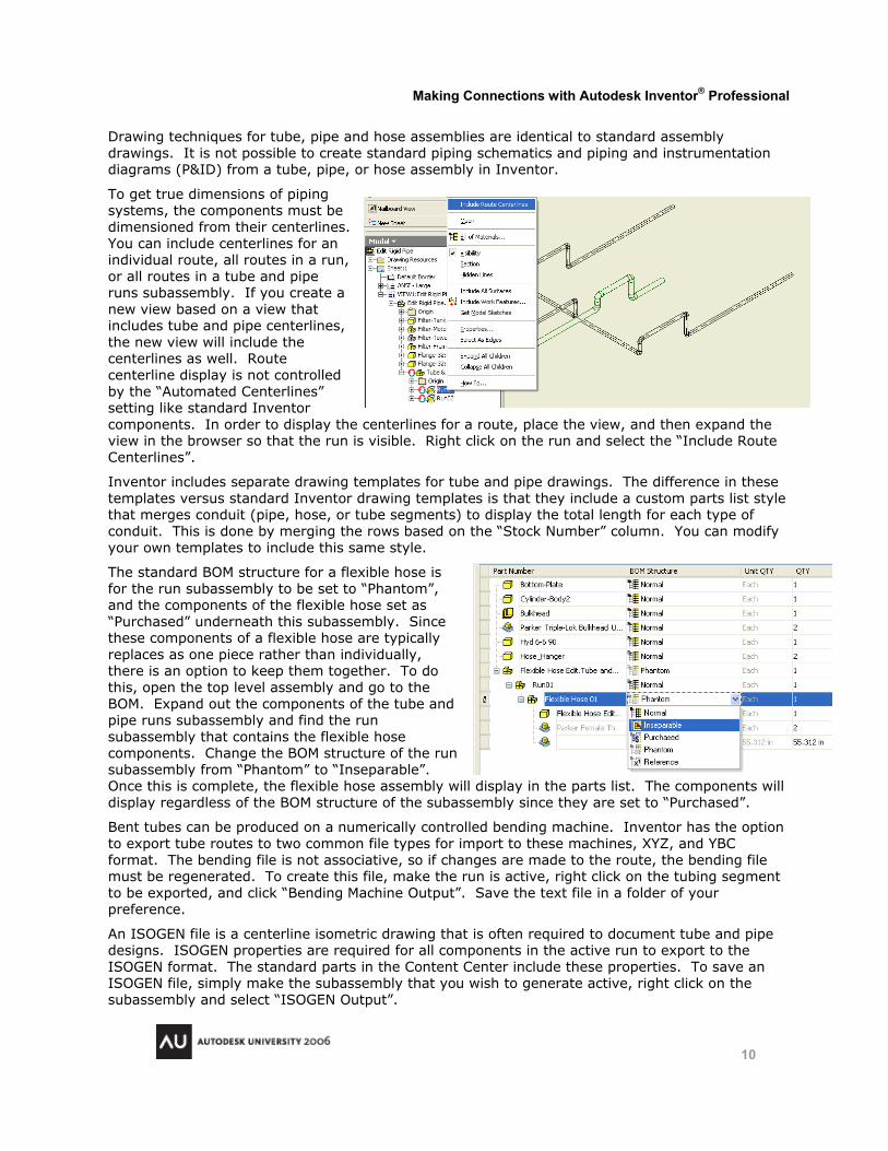
To get true dimensions of piping systems, the components must be dimensioned from their centerlines. You can include centerlines for an individual route, all routes in a run, or all routes in a tube and pipe runs subassembly. If you create a new view based on a view that includes tube and pipe centerlines, the new view will include the centerlines as well. Route centerline display is not controlled by the “Automated Centerlines” setting like standard Inventor components. In order to display the centerlines for a route, place the view, and then expand the view in the browser so that the run is visible. Right click on the run and select the “Include Route Centerlines”.
Inventor includes separate drawing templates for tube and pipe drawings. The difference in these templates versus standard Inventor drawing templates is that they include a custom parts list style that merges conduit (pipe, hose, or tube segments) to display the total length for each type of conduit. This is done by merging the rows based on the “Stock Number” column. You can modify your own templates to include this same style.
The standard BOM structure for a flexible hose is for the run subassembly to be set to “Phantom”, and the components of the flexible hose set as “Purchased” underneath this subassembly. Since these components of a flexible hose are typically replaces as one piece rather than individually, there is an option to keep them together. To do this, open the top level assembly and go to the BOM. Expand out the components of the tube and pipe runs subassembly and find the run subassembly that contains the flexible hose components. Change the BOM structure of the run subassembly from “Phantom” to “Inseparable”. Once this is complete, the flexible hose assembly will display in the parts list. The components will display regardless of the BOM structure of the subassembly since they are set to “Purchased”.
Bent tubes can be produced on a numerically controlled bending machine. Inventor has the option to export tube routes to two common file types for import to these machines, XYZ, and YBC format. The bending file is not associative, so if changes are made to the route, the bending file must be regenerated. To create this file, make the run is active, right click on the tubing segment to be exported, and click “Bending Machine Output”. Save the text file in a folder of your preference.
An ISOGEN file is a centerline isometric drawing that is often required to document tube and pipe designs. ISOGEN properties are required for all components in the active run to export to the ISOGEN format. The standard parts in the Content Center include these properties. To save an ISOGEN file, simply make the subassembly that you wish to generate active, right click on the subassembly and select “ISOGEN Output”.