336 3G Drive Test Analysis for Long Call in …E. TEMS Discovery TEMS Discovery provides the ability...
7
International Journal of Trend in Scientific Research and Development (IJTSRD) Volume 3 Issue 5, August 2019 Available Online: www.ijtsrd.com e-ISSN: 2456 – 6470 @ IJTSRD | Unique Paper ID – IJTSRD26777 | Volume – 3 | Issue – 5 | July - August 2019 Page 1764 3G Drive Test Analysis for Long Call in University Campus Aye Myat Myat Myo 1 , Zar Chi Soe 2 1 Lecturer, Department of Electronic Engineering, Pyay Technological University, Pyay, Myanmar 2 Lecturer, Department of Electronic Engineering, Technological University, Hinthata, Myanmar How to cite this paper: Aye Myat Myat Myo | Zar Chi Soe "3G Drive Test Analysis for Long Call in University Campus" Published in International Journal of Trend in Scientific Research and Development (ijtsrd), ISSN: 2456- 6470, Volume-3 | Issue-5, August 2019, pp.1764- 1767, https://doi.org/10.31142/ijtsrd26777 Copyright © 2019 by author(s) and International Journal of Trend in Scientific Research and Development Journal. This is an Open Access article distributed under the terms of the Creative Commons Attribution License (CC BY 4.0) (http://creativecommons.org/licenses/by /4.0) ABSTRACT Mobile communication is developing very rapidly with passage of time, new technologies are being introduced to facilitate the mobile user more from the technology. The past technologies are replaced by new ones and needs are growing for the new technologies to be developed. Just within a decade, an evolution of wireless service people used every day can be completely dumb founded from the roots of analog based first generation service(1G) to today’s truly broadband-ready fourth generation networks. Drive Test is conducted for checking coverage criteria of a cell site with RF Drive Test tool. The data collected by Drive Test tool as log files is analyzed to evaluate various RF parameters of the network. And it’s very important things for mobile service provider. This paper is to study about the analysis of long call Drive Test for third generation (3G) networks to evaluate the performance of QoS (Quality of Service) using TEMS Investigation 16.3.3 software and TEMS Discovery 10.0.6 software. KEYWORDS: 3G, Drive Test, Quality of Service, TEMS Investigation, TEMS Discovery . I. INTRODUCTION The Drive Test is a test performed in cellular networks regardless of technology (GSM, CDMA, UTMS, LTE, etc….). Drive Test is usually used in order to analyze and optimize the network quality. With the rapid growth of the wireless industry, GSM network are rolling out and expending at a high rate. Drive testing is a method of measuring and assessing the coverage, capacity and Quality of Service (QoS) of a mobile radio network. The technique consists of using a motor vehicle containing mobile radio network air interface measurement equipment that can detect and record a wide variety of physical and virtual parameters of mobile cellular service in a given geographical area [1]. By measuring what a wireless network subscriber would experience in any specific area, wireless carriers can make directed changes to their networks that provide better coverage and service to their customers. Drive testing requires a mobile vehicle outfitted with drive testing measurement equipment. The equipment are usually highly specialized electronic devices that interface to OEM (Original Equipment Manufacturer) mobile handsets. This ensures measurements are realistic and comparable to actual user experiences. A. Introduction to Third Generation (3G) 3G is also called third generation. It is named as such because it is the third generation of the standards of telecommunication hardware. It is also the general technology for mobile networking, passing the recent 2.5G.3G is based on GSM and was launched in 2000. The aim of this technology was to offer high speed data. The original technology was improved to allow data up to 14 Mbps and more using packet switching. It uses Wide Band Wireless Network with which clarity is increased. It also offers data services, access to television/video, new services like Global Roaming. It operates at a range of 2100MHz and has a bandwidth of 15-20MHz used for High-speed internet service, video chatting. The technology is founded on the ITU or International Telecommunication Union group of standards which belongs to the IMT-2000. There are currently widely different views throughout the wireless industry as to what constitutes a 3G wireless access network. The problem is rapidly getting worse with the increased usage of 4G to describe, in many cases, technologies that are basically just evolutions of 3G technologies [2]. 3G is a global development of communication technologies and standards. As originally proposed, the idea behind 3G was to unify the different standards used in 2G wireless networks. The third generation (3G) has been launched in several parts of the world, although the success story of 2G is hard to repeat. It has various release versions like 3.5G, 3.75G. It has more features like the data throughput is up to 3.1Mbps, has a peak upload rate of 5 Mbps. It uses turbo codes for error correction. It provides digital navigation but costly in implementation [2].The people noticed the disadvantages of Third Generation (3G) such as 3G require closer base stations which are costly. IJTSRD26777
Transcript of 336 3G Drive Test Analysis for Long Call in …E. TEMS Discovery TEMS Discovery provides the ability...

International Journal of Trend in Scientific Research and Development (IJTSRD)
Volume 3 Issue 5, August 2019 Available Online: www.ijtsrd.com e-ISSN: 2456 – 6470
@ IJTSRD | Unique Paper ID – IJTSRD26777 | Volume – 3 | Issue – 5 | July - August 2019 Page 1764
3G Drive Test Analysis for Long Call in University Campus
Aye Myat Myat Myo1, Zar Chi Soe2
1Lecturer, Department of Electronic Engineering, Pyay Technological University, Pyay, Myanmar 2Lecturer, Department of Electronic Engineering, Technological University, Hinthata, Myanmar
How to cite this paper: Aye Myat Myat
Myo | Zar Chi Soe "3G Drive Test Analysis
for Long Call in University Campus"
Published in International Journal of
Trend in Scientific
Research and
Development
(ijtsrd), ISSN: 2456-
6470, Volume-3 |
Issue-5, August
2019, pp.1764-
1767,
https://doi.org/10.31142/ijtsrd26777
Copyright © 2019 by author(s) and
International Journal of Trend in Scientific
Research and Development Journal. This
is an Open Access article distributed
under the terms of
the Creative
Commons Attribution
License (CC BY 4.0)
(http://creativecommons.org/licenses/by
/4.0)
ABSTRACT
Mobile communication is developing very rapidly with passage of time, new
technologies are being introduced to facilitate the mobile user more from the
technology. The past technologies are replaced by new ones and needs are
growing for the new technologies to be developed. Just within a decade, an
evolution of wireless service people used every day can be completely dumb
founded from the roots of analog based first generation service(1G) to today’s
truly broadband-ready fourth generation networks.
Drive Test is conducted for checking coverage criteria of a cell site with RF
Drive Test tool. The data collected by Drive Test tool as log files is analyzed to
evaluate various RF parameters of the network. And it’s very important things
for mobile service provider. This paper is to study about the analysis of long
call Drive Test for third generation (3G) networks to evaluate the performance
of QoS (Quality of Service) using TEMS Investigation 16.3.3 software and TEMS
Discovery 10.0.6 software.
KEYWORDS: 3G, Drive Test, Quality of Service, TEMS Investigation, TEMS
Discovery .
I. INTRODUCTION
The Drive Test is a test performed in cellular networks regardless of technology
(GSM, CDMA, UTMS, LTE, etc….). Drive Test is usually used in order to analyze
and optimize the network quality. With the rapid growth of the wireless
industry, GSM network are rolling out and expending at a high rate.
Drive testing is a method of measuring and assessing the
coverage, capacity and Quality of Service (QoS) of a mobile
radio network.
The technique consists of using a motor vehicle containing
mobile radio network air interface measurement equipment
that can detect and record a wide variety of physical and
virtual parameters of mobile cellular service in a given
geographical area [1].
By measuring what a wireless network subscriber would
experience in any specific area, wireless carriers can make
directed changes to their networks that provide better
coverage and service to their customers.
Drive testing requires a mobile vehicle outfitted with drive
testing measurement equipment. The equipment are usually
highly specialized electronic devices that interface to OEM
(Original Equipment Manufacturer) mobile handsets. This
ensures measurements are realistic and comparable to
actual user experiences.
A. Introduction to Third Generation (3G)
3G is also called third generation. It is named as such
because it is the third generation of the standards of
telecommunication hardware. It is also the general
technology for mobile networking, passing the recent
2.5G.3G is based on GSM and was launched in 2000. The aim
of this technology was to offer high speed data. The original
technology was improved to allow data up to 14 Mbps and
more using packet switching. It uses Wide Band Wireless
Network with which clarity is increased. It also offers data
services, access to television/video, new services like Global
Roaming. It operates at a range of 2100MHz and has a
bandwidth of 15-20MHz used for High-speed internet
service, video chatting.
The technology is founded on the ITU or International
Telecommunication Union group of standards which belongs
to the IMT-2000.
There are currently widely different views throughout the
wireless industry as to what constitutes a 3G wireless access
network. The problem is rapidly getting worse with the
increased usage of 4G to describe, in many cases,
technologies that are basically just evolutions of 3G
technologies [2]. 3G is a global development of communication
technologies and standards. As originally proposed, the idea
behind 3G was to unify the different standards used in 2G
wireless networks.
The third generation (3G) has been launched in several parts
of the world, although the success story of 2G is hard to
repeat. It has various release versions like 3.5G, 3.75G. It has
more features like the data throughput is up to 3.1Mbps, has
a peak upload rate of 5 Mbps. It uses turbo codes for error
correction. It provides digital navigation but costly in
implementation [2].The people noticed the disadvantages of
Third Generation (3G) such as 3G require closer base
stations which are costly.
IJTSRD26777

International Journal of Trend in Scientific Research and Development (IJTSRD) @ www.ijtsrd.com eISSN: 2456-6470
@ IJTSRD | Unique Paper ID – IJTSRD26777 | Volume – 3 | Issue – 5 | July - August 2019 Page 1765
B. Introduction to DRIVE TEST System
Drive Test is a method of measuring and assessing of
wireless network. Drive Test performance measurements
are carried out for the following reasons: Test the network
from the subscriber’s point of view. Test the complete
system, end to end. Bench mark performance against
competitor networks. Test specific important routes and
areas. Test in-building coverage for specific buildings (Metro,
Airport, office etc.) called walk test [4].
Figure 1 Drive Test System
C. Third Generation Long Call for Drive Test
Everything depends on the technology (GSM, CDMA, UMTS,
etc. ...) and the purpose of the test as always. The Drive Test
is performed according to the need, and the types of test
calls are the same that the network supports - calls can be
voice, data, video, etc. A typical Drive Test uses two phones.
With this, the researcher collects specific data in IDLE and
CALL modes for the network. The calls test (CALL) can be of
two types: long or short duration. Long calls serve to verify if
the handovers (continuity between the cells) of the network
are working, i.e. calls must not drop.
II. REQUIRED COMPONENTS FOR DRIVE TEST
Every good RF design, after its implantation should be
evaluated. There are few ways to do this, for example
through analysis of KPI (Key Performance Indicator) or
through prediction tools and signal interference. Other very
common and efficient way to evaluate the network is
conducting a Drive Test.
The name is intuitive: take a drive test. The Drive Test is a
test performed in cellular networks regardless of technology
(GSM, CDMA, UMTS, LTE, etc. ...).Means collecting data on
vehicle movement. Its variation has also intuitive: Walk Test,
i.e. collect data by walking areas of interest.
The analyses of drive test are fundamental for the work of
any professional in the field of IT and Telecom comprising
two phases: data collection and data analysis.
Although through the analysis of KPI's we can identify
problems such as dropped calls, among others, the drive
tests allow a deeper analysis in field. Identifying areas of
each sector of coverage, interference, evaluation of network
changes and various other parameters.
A. Drive Test
Drive Test, as already mentioned, is the procedure to
perform a test while driving. The vehicle does not really
matter; people can do a drive test using a motorcycle or
bicycle. What matters is the hardware and software used in
the test.
� A notebook - or other similar device
� with collecting Software installed and
� one GPS
Also is common the use of adapters and / or hubs that allow
the correct interconnection of all equipment. The following
figure is a schematic of the standard connections.
Figure 2.Drive Test Tools
The main goal is to collect test data, but they can be viewed /
analyzed in real time (Live) during the test, allowing a view
of network performance on the field. Data from all units are
grouped by collection software and stored in one or more
output files.
� GPS: collecting the data of latitude and longitude of each
point / measurement data, time, speed, etc... It is also
useful as a guide for following the correct routes.
� MS: mobile data collection, such as signal strength, best
server, etc ...
The minimum required to conduct a drive test, simplifying, is
a mobile device with software to collect data and a GPS.
Currently, there are already cell phones that do everything.
They have a GPS, as well as a collection of specific software.
They are very practical, but are still quite expensive [2].
B. Drive Test Tools
There are two portions for TEMS Drive Test Tools
hardware and software.
Hardware tools are as follows:
� Laptop
� GPS
� Dongle
� MDM 9200
� Sony Ericsson W995
� SIM Card
Software tools are as follows:
� TEMS Investigation 16.3.3
� TEMS Discovery 10.0.6
� MPT Cell File
C. Drive Test Route
Drive Test routes are the first step to be set, and indicate
where testing will occur. This area is defined based on
several factors, mainly related to the purpose of the test. The
routes are predefined in the office. A program of a lot of help
in this area is Google Earth. A good practice is to trace the
route on the same using the easy paths or polygons. The final
image can then be brought to the driver.

International Journal of Trend in Scientific Research and Development (IJTSRD) @ www.ijtsrd.com eISSN: 2456-6470
@ IJTSRD | Unique Paper ID – IJTSRD26777 | Volume – 3 | Issue – 5 | July - August 2019 Page 1766
Some software allows the image to be loaded as the software
background (geo-referenced). This makes it much easier to
direct routes to be followed. It is advisable to check traffic
conditions by tracing out the exact pathways through which
the driver must pass. It is clear that the movement of
vehicles is always subject to unforeseen events, such as
congestion, interdicted roads, etc. Therefore, one should
always have on hand - know - alternate routes to be taken on
these occasions.
Figure 3 Rout Testing
Avoid running the same roads multiple times during a Drive
Test (use the Pause if needed). A route with several passages
in the same way is more difficult to interpret.
Types of Drive Test
The main types of Drive Test are:
� Performance Analysis
� Integration of New Sites and change parameters
of Existing Sites
� Marketing
� Benchmarking
D. TEMS Investigation
TEMS Investigation used in more than 180 countries
worldwide data collection. It is the industry standard tool for
troubleshooting, verification, optimization and maintenance
of wireless networks. It supports all major technologies,
making it the ideal testing tool at every stage of the
network’s life cycle. It has been the leading originator of
drive testing features and functions for two decades. It is a
complete, cost-effective and conveniently compact solution
for active field engineer.
E. TEMS Discovery
TEMS Discovery provides the ability to analyze drive test log
files and generate reports.
� New post processing tool within the Ascom TEMS
portfolio
� Designed but can also be used for Benchmarking and
QoS verification
� Flexible tool that is easy to adapt to the working process
� Automated data processing
� User defined KIPs
� Inbuilt reporting
� Excellent post processing solution for TEMS
Investigation and TEMS Pocket
F. Technology Support
TEMS Discovery can support the following technology. So
the network quality of these items can be analyzed by
using TEMS Discovery.
� IS -95/CDMA20000 1x
� EV-DO (Rev.0/ Rev. A)
� GSM/GPRS/EDGE
� WCDMA/HSDPA/HSUPA/HSPA+
� TD-SCDMA
� WiMAX and
� LTE
III. IMPLEMENTATION OF TEMS INVESTIGATION
The Investigator goes to file menu option in order to create a
new workspace and then selects new one as shown in Fig.4
(a).
(a) Creating New Workspace (b) Taking Map
Figure 4.Creating Workspace and Taking Map
After creating a new workspace, the investigator chooses the
presentation menu and then selects positioning to take a
map as shown in Fig 4(b).
In that presentation menu, it is needed to select GSM for 2G
and chooses Serving/Neighbor Cell.
The user must select 2G radio parameters in GSM of
presentation menu. The next step is choosing the current
channel. After selecting radio parameters, radio current
channel is chosen for GSM.
After finishing above procedures, the investigator got the
events from signaling.
The following procedures are implementation for WCDMA.
In that presentation menu, it is needed to select WCDMA for
3G and chooses Serving/Neighbor Cell as shown in Fig 5(a).
Figure 5.WCDMA Serving/Neighbor Cell
The user must select 3G radio parameters in WCDMA of
presentation menu.
This step is choosing the serving cell. After selecting
serving cell, serving call channel is chosen for WCDMA as
shown in Fig 6.

International Journal of Trend in Scientific Research and Development (IJTSRD) @ www.ijtsrd.com eISSN: 2456-6470
@ IJTSRD | Unique Paper ID – IJTSRD26777 | Volume – 3 | Issue – 5 | July - August 2019 Page 1767
Figure 6 WCDMA Serving Cell
When the user wants to view HSDPA analysis, it goes to
presentation menu and selects Data Service in WCDMA. The
user can choose HSDPA analysis as shown in Fig 7.
Figure 7 WCDMA Data Service
After finishing above procedures, the investigator got the
events from signaling as shown in Fig 8.
Figure 8 3G Events Option
The following fig 9 shows deactivated and activated
saturation of MDM 9200, GPS and Sony Ericsson W 995.
(a)Deactivated Condition (b) Activated Condition
Figure 9 Deactivated and Activated Condition of
Equipments
In order to lock WCDMA, goes to control option and then
selects radio access technology. After selecting radio access
technology, in this way, WCDMA can be locked. In order to
record the log files, goes to file menu and selects option and
then selects recording. After finish recording option, to add
cell file go to configuration menu select general and then add
cell file. When it is complete all steps, the investigator can
start overshooting (routing) and data collections. This
condition is shown in Fig 10.
Figure 10 overshooting and Data collecting
A. Implementation of TEMS Discovery
Firstly, to create new project, go to project menu select new
project and define project name after all select save and
close as shown in Fig 11(a).
(a)Creating New Project (b) Defining Devices
(MS1,MS2, etc)
Figure 11.Creating Project and Defining Devices
After creating new project, to define devices such as MS1,
MS2 go to composite (integrated) and then select device is
shown as Fig 11(b).
The investigator can take data from MS1, MS2 fill to the
member of group select new menu and fill data.
The Data Set tab displays drive test data in logical group:
Archived, Composite and data Sets. Except for the archived
dataset, each group is in a tree view layout that can be drilled
down to the metric level shown in Fig 12.
Figure 12 Data Set
IV. TEST AND RESULTS
In this paper, the analyzed results of the parameters such as
Cell ID Server, RxLev Sub, Rxqual Full, and Handover Success

International Journal of Trend in Scientific Research and Development (IJTSRD) @ www.ijtsrd.com eISSN: 2456-6470
@ IJTSRD | Unique Paper ID – IJTSRD26777 | Volume – 3 | Issue – 5 | July - August 2019 Page 1768
Rate by using TEMS Discovery 10.0.6 are described.
Moreover, the analytical results of perfomance comparison
of operators (MPT) are discussed.
A. Legend
The following Table is used in TEMS Discovery to define
what color excellent, very good, good, average, weak and
bad.
Table 4.1 Legend Explanation
Color Red Green Blue Condition
0 0 153 Excellent
0 0 255 Very Good
0 255 0 Good
255 255 0 Average
255 192 0 Weak
255 0 0 Bad
B. Comparison Agg.Active Ec/Io Result For MPT of 3G Day 1,2,3
The following figure shows the Comparison Results of Agg.Active Ec/Io in 3G for MPT Day 1, 2 and 3. According to Fig. 4.13,in
Day 1, the value of Agg.Active Ec/Io of 3G for MPT is (94.29%) ,in Day2, (99.38%) and the value of Agg.Active Ec/Io is only
(94.29%) in Day3. Among these days, in Day 2, the value of Agg.Active Ec/Io of 3G for MPT is the best.
(a)MPT Day 1 (b)MPT Day 2 (c)MPT Day 3
Figure 13.Comparison Agg.Active Ec/Io Result For MPT in Day 1,2,3
C. Comparison Agg.Active RSCP Results For MPT of 3G in Day 1,2,3
The following figure shows the Comparison Results of Agg.Active RSCP in 3G for MPT in Day 1, 2 and 3. According to Fig. 4.16,
the value of Agg.Active RSCP of 3G for MPT is only (81.43%), in Day 2, (83.22%)and the value of Agg.Active RSCP Result of MPT
is (81.43%) in Day 3. So in Day 2, the received signal code power(RSCP) is fair in university compus.
(a)MPT Day 1 (b)MPT Day 2 (c)MPT Day 3
Figure 14. Comparison Agg.Active RSCP Result For MPT in Day 1,2,3
D. Comparison Voice Call Setup Success Rate Result For MPT 3G Day 1,2,3
The following figure shows Comparison Results of 3G Voice Call Setup Success Rate For MPT in Day 1,2,3. In these days, Voice
Call Setup Success Rate is 100% all.
(a)Day 1 (b)Day (c)Day 3
Figure 15.Comparison Voice Call Setup Success Rate Result For MPT 3G Day 1,2,3
E. Comparison Handover Success Rate Result For MPT 3G in Day 1,2,3
The following figure shows Comparison Results of 3G Handover Success Rate For MPT in Day 1,2,3.
International Journal of Trend in Scientific Research and Development (IJTSRD) @ www.ijtsrd.com eISSN: 2456-6470
@ IJTSRD | Unique Paper ID – IJTSRD26777 | Volume – 3 | Issue – 5 | July - August 2019 Page 1769
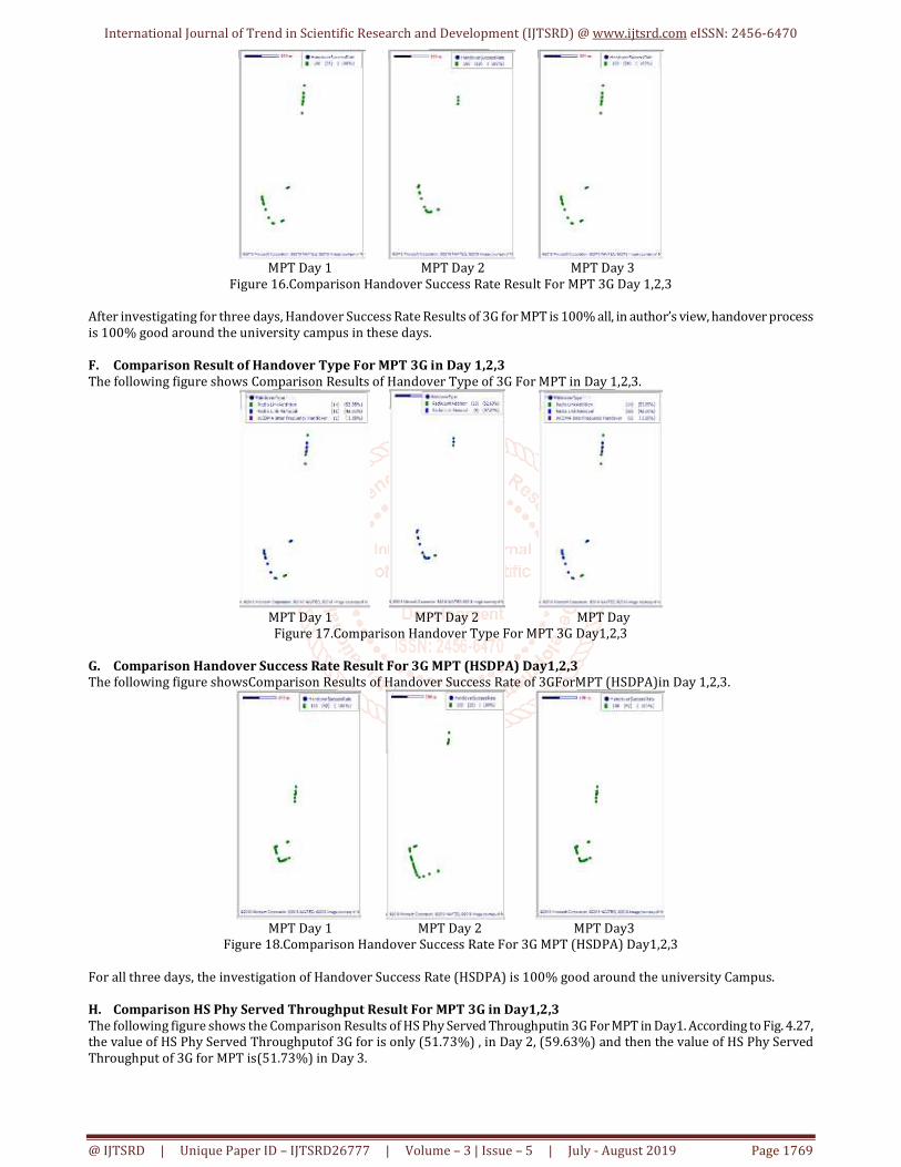
MPT Day 1 MPT Day 2 MPT Day 3
Figure 16.Comparison Handover Success Rate Result For MPT 3G Day 1,2,3
After investigating for three days, Handover Success Rate Results of 3G for MPT is 100% all, in author’s view, handover process
is 100% good around the university campus in these days.
F. Comparison Result of Handover Type For MPT 3G in Day 1,2,3
The following figure shows Comparison Results of Handover Type of 3G For MPT in Day 1,2,3.
MPT Day 1 MPT Day 2 MPT Day
Figure 17.Comparison Handover Type For MPT 3G Day1,2,3
G. Comparison Handover Success Rate Result For 3G MPT (HSDPA) Day1,2,3
The following figure showsComparison Results of Handover Success Rate of 3GForMPT (HSDPA)in Day 1,2,3.
MPT Day 1 MPT Day 2 MPT Day3
Figure 18.Comparison Handover Success Rate For 3G MPT (HSDPA) Day1,2,3
For all three days, the investigation of Handover Success Rate (HSDPA) is 100% good around the university Campus.
H. Comparison HS Phy Served Throughput Result For MPT 3G in Day1,2,3
The following figure shows the Comparison Results of HS Phy Served Throughputin 3G For MPT in Day1. According to Fig. 4.27,
the value of HS Phy Served Throughputof 3G for is only (51.73%) , in Day 2, (59.63%) and then the value of HS Phy Served
Throughput of 3G for MPT is(51.73%) in Day 3.

International Journal of Trend in Scientific Research and Development (IJTSRD) @ www.ijtsrd.com eISSN: 2456-6470
@ IJTSRD | Unique Paper ID – IJTSRD26777 | Volume – 3 | Issue – 5 | July - August 2019 Page 1770
MPT Day1 MPT Day2 MPT Day 3
Figure 19. Comparison HS Phy Served Throughput Result For MPT 3G Day1,2,3
After investigating for three days, the value of HS Phy Served Throughput Result for Day2 is better than the other days.
V. CONCLUSION
This paper represents about Drive Test System used in
university campus. In this paper, the author can analyze 3G
network using Drive Test TEMS software for long call.
Especially, the researcher can analyze the basic parameters
such as Cell ID Server, RxQualFull, Handover Success Rate,
Handover Type, Agg.Active Ec/Io, Agg.Active RSCPand HS
Phy Served Throughput.The author can be remarked the
parameters whether good or bad because of the help of
legend.In this work,the people can study about the
comparison of quality of network within three days for the
operators MPT.Aftr analysising, the researcher could know
about the quality of network around the university campus.
In the author’s view, there were many problems in this
analysis.The problem are that the matching of the software
and the window of PC is necessary.Cell file is also problem to
PC.There is problem to install some software.The author
hopes more better solution of this analysis if there has
sufficient time.
ACKNOWLEDGEMENT
I would like to acknowledge the many colleagues at Pyay
Technological University who have contributed to the
passing this research paper.
REFERENCES
[1] Comparative Study on Wireless Mobile Technology:
1G, 2G, 3G, 4G and 5G, Pandya Gujarat Technological
University, Gujarat, India,
https://pdfs.semanticscholar.org
[2] Development of Wireless Communication Networks:
From 1G to 5G, Shivam Jaiswal 1,Ajay Kumar 2, Neha
Kumari 3, https://www.ijecs.in
[3] Transformation of Mobile Communication Network
from 1G to 4G and 5G, Mohammad Javed and Ahmad
Talha Siddiqui, Department of computer science and
technology,Maulana Azad National Urdu University,
Hyderabad, Telangana, India, www.ijrcs.info
[4] Atif Mugdam jaheldeen: Handover Drive Test,Vol
.22,Issue 01,www.ijeam.com
[5] Evolution of Mobile Generation Technology: 1G to 5G
and review of upcoming wireless technology 5G, Ms.
Lopa J. Vora, https://pdfs.semanticscholar.org