32424 BLH 500X manual - · PDF fileF5 BLH1827 Servo Mounting Tab Set: B500 3D/X ... F7...
24
60 H11 H3 B6 B3 H10 H10 H1 H4 H4 H8 H11 H5 B1 H13 B5 H3 H4 B6 B3 H11 H6 H10 H10 H14 H15 H7 H18 H16 H7 H9 H17 H16 H5 H12 H2 H2 B3 H4 H8 H4 H1 B3
Transcript of 32424 BLH 500X manual - · PDF fileF5 BLH1827 Servo Mounting Tab Set: B500 3D/X ... F7...
60
H11
H3
B6 B3
H10
H10
H1
H4
H4
H8 H11 H5
B1
H13
B5
H3
H4
B6
B3
H11
H6
H10
H10
H14
H15
H7 H18
H16
H7
H9
H17
H16
H5
H12
H2
H2
B3H4
H8
H4
H1
B3
61
M9
M9
M9
M2
M2
M3
M3
M10
M10
M10
F17
F12 F1
6F6F1
4
B7
F2
F3
F8
B7
F7
M8
F17
F6F1
0
F9
F13
F4
F20
F19
F18
F15
F1
F11
F9
F6
F10
62
T5
T8
T3
T7
T15
T13B5B2
T14B2
T13
T14
T15
T13
B2
B2
B5
T12
B1
B2
B2
T11
T10
T9B1T1
1
T9T9
T8
T16
T8
T6
T4
T1
M9
T17
T17
T17
M10
T2
63
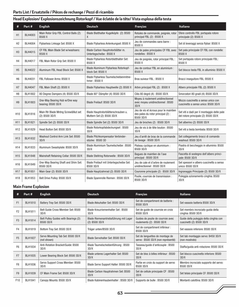
# Part # English Deutsch Françias Italiano
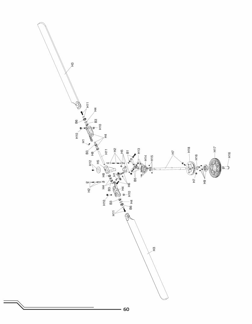
H1 BLH4003Main Rotor Grip FBL Control Balls (2):
B500 X
Blade Blatthalter Kugelköpfe (2): B500
X
Rotules de commande, poignée, rotor principal FBL (2) : B500 X
Sfere controllo FBL portapala rotore
principale (2): B500 X
H2 BLH4004 Flybarless Linkage Set: B500 X Blade Flybarless Anlenkungset: B500 XJeu de commandes sans barre : B500 X
Set di leveraggi senza fl ybar: B500 X
H3 BLH4015CF FBL Main Blade Set w/washsers:
B500 X
Blade Carbon Hauptrotorblätter m.
Unterlegscheibe : B500 X
Jeu de pales principales CF FBL avec rondelles : B500 X
Set pala principale CF FBL con rondelle:
B500 X
H4 BLH4017 FBL Main Rotor Grip Set: B500 XBlade Flybarless Rotorblatthalter Set:
B500 X
Jeu de poignée, rotor principal FBL : B500 X
Set portapala rotore principale FBL:
B500 X
H5 BLH4022 Aluminum FBL Head Block Set: B500 XBlade Aluminum Flybarless Rotorkopf-
block Set: B500 X
Jeu de contour FBL en aluminium : B500 X
Set blocco testa FBL in alluminio: B500 X
H6 BLH4031 FBL Follower Arms: B500 XBlade Flybarless Taumelscheibenmitne-
hmer : B500 XBras suiveur FBL : B500 X Bracci inseguitore FBL: B500 X
H7 BLH4047 FBL Main Shaft (2): B500 X Blade Flybarless Hauptwelle (2): B500 X Arbre principal FBL (2) : B500 X Albero principale FBL (2): B500 X
H8 BLH1802 80 Degree Dampers (4): B500 3D/X Blade 80° Dämpfer (4): B500 3D/X Clés 80 degré (4) : B500 3D/X Smorzatori 80 gradi (4): B500 3D/X
H9 BLH1803One-Way Bearing Hub w/One way
bearing: B500 3D/XBlade Freilauf: B500 3D/X
Moyeu à roulement unidirectionnel avec moyeu unidirectionnel : B500 3D/X
Mozzo cuscinetto a senso unico con
cuscinetto a senso unico: B500 3D/X
H10 BLH1816Main Rtr Blade Mntng Screw&Nut set
(2): B500 3D/X
Blade Hauptrotorblätterschrauben u.
Muttern Set (2): B500 3D/X
Jeu de vis et écrous pour le maintien des pales du rotor principal (2) : B500 3D/X
Set viti e dadi per il montaggio delle pale
del rotore principale (2): B500 3D/X
H11 BLH1821 Spindle Set (2): B500 3D/X Blade Spindle Set (2): B500 3D/X Jeu de broches (2) : B500 3D/X Set alberino (2): B500 3D/X
H12 BLH1829 Head Button Set: B500 3D/XBlade Rotorkopfabdeckungset : B500
3D/X
Jeu de vis à de tête bouton : B500 3D/X
Set viti a testa bombata: B500 3D/X
H13 BLH1832Washout Control Arm Link Set: B500
3D/X
Blade Pitchkompensator Verbinder-
stücke: B500 3D
Jeu d’arrêt de bras de la commande de lavage : B500 3D/X
Set collegamento bracci di comando
washout: B500 3D/X
H14 BLH1833 Aluminum Swashplate: B500 3D/XBlade Aluminium Taumelscheibe : B500
3D/X
Plateau cyclique en aluminium : B500 3D/X
Piastra di beccheggio in alluminio: B500
3D/X
H15 BLH1848 Mainshaft Retaining Collar: B500 3D/X Blade Stellring Rotorwelle : B500 3D/XBagues de maintien de l’axe principal : B500 3D/X
Fascetta di sostegno dell’albero princi-
pale: B500 3D/X
H16 BLH1849One-Way Bearing Shaft and Shim Set:
B500 3D/X
Blade Freilauf mit Unterlegscheibe Set:
B500 3D/X
Jeu de cale et d’arbre de roulement unidirectionnel : B500 3D/X
Set spessori e albero cuscinetto a senso
unico: B500 3D/X
H17 BLH1851 Main Gear (2): B500 3D/X Blade Hauptzahnrad (2): B500 3D/X Couronne principale (2) : B500 3D/X Ingranaggio Principale (2): B500 3D/X
H18 BLH1853 Belt Drive Pulley: B500 3D/X Blade Spannrolle Riemen : B500 3D/XPoulie, courroie de transmission : B500 3D/X
Puleggia azionamento cinghia: B500
3D/X
Parts List / Ersatzteile / Pièces de rechange / Pezzi di ricambio
# Part # English Deutsch Françias Italiano
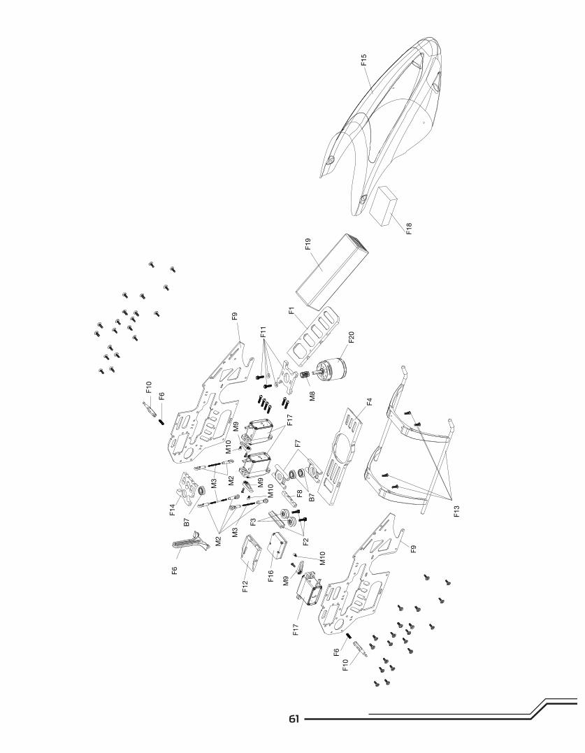
F1 BLH1810 Battery Tray Set: B500 3D/X Blade Akkuhalter Set: B500 3D/XSet de compartiment de batterie :
B500 3D/XSet vassoio batteria B500 3D/X
F2 BLH1811Belt Guide Cross Member Set: B500
3D/X
Blade Kreuzriemenhalter Set : B500
3D/X
Set de guide de courroie en croix
B500 3D/X
Set membro incrociato guida della
cinghia: B500 3D/X
F3 BLH1814Belt Pulley Guides with Bearings (2):
B500 3D/X
Blade Riemenantriebsführung mit Lager
(2): B500 3D/X
Guides de poulie de courroie avec
roulements (2) : B500 3D/X
Guide della puleggia della cinghia con
cuscinetti (2): B500 3D/X
F4 BLH1819 Bottom Tray Set: B500 3D/X Träger unten/B500 3D/X Set de compartiment inférieur :
B500 3D/XSet vassoio inferiore: B500 3D/X
F5 BLH1827Servo Mounting Tab Set: B500 3D/X
(not shown)Blade Servohalter Set: B500 3D/X
Set de languettes de montage de
servo : B500 3D/X (non représenté)
Set tab montaggio servo: B450 3D/X
(non mostrato)
F6 BLH1834Anti-Rotation Bracket/Guide: B500
3D/X
Blade Taumelscheibenführung : B500
3D/X
Tasseau/guide d'anticouple : B500
3D/XStaffa/guida anti-rotazione: B500 3D/X
F7 BLH1835 Lower Bearing Block Set: B500 3D/XBlade unteres Lagerhalter Set: B500
3D/X
Set de bloc à billes inférieur : B500
3D/X
Set blocco cuscinetto inferiore: B500
3D/X
F8 BLH1836Servo Support Cross Member: B500
3D/XBlade Servo Support Halter: B500 3D/X
Partie en croix du support de servo
B500 3D/X
Membro incrociato supporto del servo:
B500 3D/X
F9 BLH1839 CF Main Frame Set: B500 3D/XBlade Carbon Hauptrahmen Set: B500
3D/X
Set de cellule principale CF : B500
3D/XSet telaio principale CF: B500 3D/X
F10 BLH1841 Canopy Mounts: B500 3D/X Blade Kabinenhaubenhalter : B500 3D/X Supports de bulle : B500 3D/X Montanti calottina: B500 3D/X
Main Frame Explosion
Head Explosion/ Explosionszeichnung Rotorkopf / Vue éclatée de la tête/ Vista esplosa della testa
64
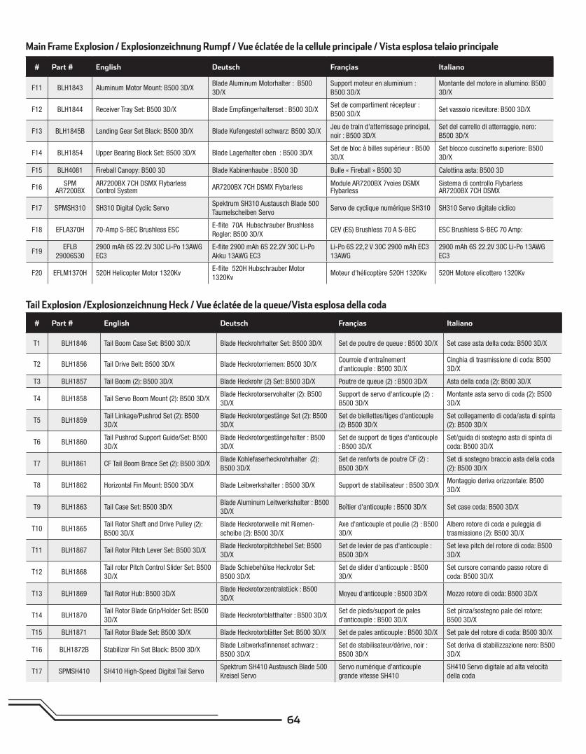
# Part # English Deutsch Françias Italiano
F11 BLH1843 Aluminum Motor Mount: B500 3D/XBlade Aluminum Motorhalter : B500
3D/X
Support moteur en aluminium :
B500 3D/X
Montante del motore in allumino: B500
3D/X
F12 BLH1844 Receiver Tray Set: B500 3D/X Blade Empfängerhalterset : B500 3D/XSet de compartiment récepteur :
B500 3D/XSet vassoio ricevitore: B500 3D/X
F13 BLH1845B Landing Gear Set Black: B500 3D/X Blade Kufengestell schwarz: B500 3D/XJeu de train d'atterrissage principal,
noir : B500 3D/X
Set del carrello di atterraggio, nero:
B500 3D/X
F14 BLH1854 Upper Bearing Block Set: B500 3D/X Blade Lagerhalter oben : B500 3D/XSet de bloc à billes supérieur : B500
3D/X
Set blocco cuscinetto superiore: B500
3D/X
F15 BLH4081 Fireball Canopy: B500 3D Blade Kabinenhaube : B500 3D Bulle « Fireball » B500 3D Calottina asta: B500 3D
F16SPM
AR7200BXAR7200BX 7CH DSMX Flybarless Control System
AR7200BX 7CH DSMX FlybarlessModule AR7200BX 7voies DSMX Flybarless
Sistema di controllo Flybarless AR7200BX 7CH DSMX
F17 SPMSH310 SH310 Digital Cyclic ServoSpektrum SH310 Austausch Blade 500
Taumelscheiben ServoServo de cyclique numérique SH310 SH310 Servo digitale ciclico
F18 EFLA370H 70-Amp S-BEC Brushless ESCE-fl ite 70A Hubschrauber Brushless
Regler: B500 3D/XCEV (ES) Brushless 70 A S-BEC ESC Brushless S-BEC 70 Amp:
F19EFLB
29006S30
2900 mAh 6S 22.2V 30C Li-Po 13AWG
EC3
E-fl ite 2900 mAh 6S 22.2V 30C Li-Po
Akku 13AWG EC3
Li-Po 6S 22,2 V 30C 2900 mAh EC3
13AWG
2900 mAh 6S 22.2V 30C Li-Po 13AWG
EC3
F20 EFLM1370H 520H Helicopter Motor 1320KvE-fl ite 520H Hubschrauber Motor
1320KvMoteur d'hélicoptère 520H 1320Kv 520H Motore elicottero 1320Kv
# Part # English Deutsch Françias Italiano
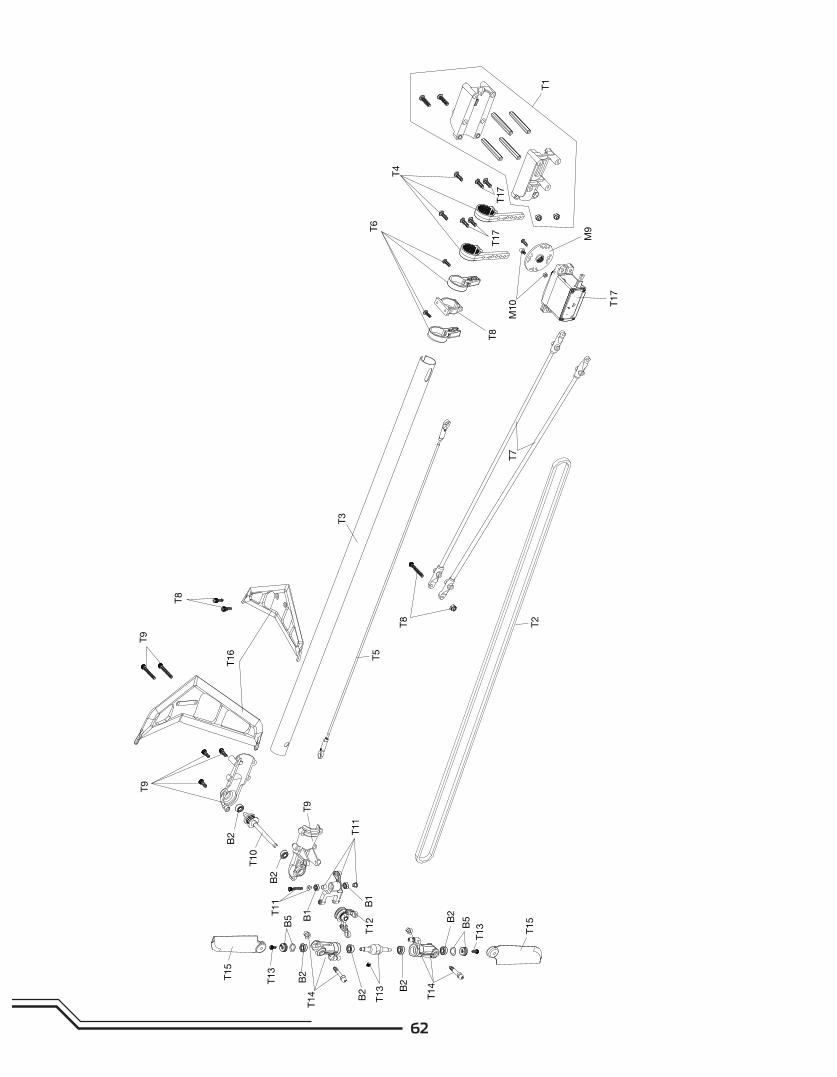
T1 BLH1846 Tail Boom Case Set: B500 3D/X Blade Heckrohrhalter Set: B500 3D/X Set de poutre de queue : B500 3D/X Set case asta della coda: B500 3D/X
T2 BLH1856 Tail Drive Belt: B500 3D/X Blade Heckrotorriemen: B500 3D/XCourroie d'entraînement
d'anticouple : B500 3D/X
Cinghia di trasmissione di coda: B500
3D/X
T3 BLH1857 Tail Boom (2): B500 3D/X Blade Heckrohr (2) Set: B500 3D/X Poutre de queue (2) : B500 3D/X Asta della coda (2): B500 3D/X
T4 BLH1858 Tail Servo Boom Mount (2): B500 3D/XBlade Heckrotorservohalter (2): B500
3D/X
Support de servo d'anticouple (2) :
B500 3D/X
Montante asta servo di coda (2): B500
3D/X
T5 BLH1859Tail Linkage/Pushrod Set (2): B500
3D/X
Blade Heckrotorgestänge Set (2): B500
3D/X
Set de biellettes/tiges d'anticouple
(2) B500 3D/X
Set collegamento di coda/asta di spinta
(2): B500 3D/X
T6 BLH1860Tail Pushrod Support Guide/Set: B500
3D/X
Blade Heckrotorgestängehalter : B500
3D/X
Set de support de tiges d'anticouple
: B500 3D/X
Set/guida di sostegno asta di spinta di
coda: B500 3D/X
T7 BLH1861 CF Tail Boom Brace Set (2): B500 3D/XBlade Kohlefaserheckrohrhalter (2):
B500 3D/X
Set de renforts de poutre CF (2) :
B500 3D/X
Set di sostegno braccio asta della coda
(2): B500 3D/X
T8 BLH1862 Horizontal Fin Mount: B500 3D/X Blade Leitwerkshalter : B500 3D/X Support de stabilisateur : B500 3D/XMontaggio deriva orizzontale: B500
3D/X
T9 BLH1863 Tail Case Set: B500 3D/XBlade Aluminum Leitwerkshalter : B500
3D/XBoîtier d'anticouple : B500 3D/X Set case coda: B500 3D/X
T10 BLH1865Tail Rotor Shaft and Drive Pulley (2):
B500 3D/X
Blade Heckrotorwelle mit Riemen-
scheibe (2): B500 3D/X
Axe d'anticouple et poulie (2) : B500
3D/X
Albero rotore di coda e puleggia di
trasmissione (2): B500 3D/X
T11 BLH1867 Tail Rotor Pitch Lever Set: B500 3D/XBlade Heckrotorpitchhebel Set: B500
3D/X
Set de levier de pas d'anticouple :
B500 3D/X
Set leva pitch del rotore di coda: B500
3D/X
T12 BLH1868Tail rotor Pitch Control Slider Set: B500
3D/X
Blade Schiebehülse Heckrotor Set:
B500 3D/X
Set de slider d'anticouple : B500
3D/X
Set cursore comando passo rotore di
coda: B500 3D/X
T13 BLH1869 Tail Rotor Hub: B500 3D/XBlade Heckrotorzentralstück : B500
3D/XMoyeu d'anticouple : B500 3D/X Mozzo rotore di coda: B500 3D/X
T14 BLH1870Tail Rotor Blade Grip/Holder Set: B500
3D/XBlade Heckrotorblatthalter : B500 3D/X
Set de pieds/support de pales
d'anticouple : B500 3D/X
Set pinza/sostegno pale del rotore:
B500 3D/X
T15 BLH1871 Tail Rotor Blade Set: B500 3D/X Blade Heckrotorblätter Set: B500 3D/X Set de pales anticouple : B500 3D/X Set pale del rotore di coda: B500 3D/X
T16 BLH1872B Stabilizer Fin Set Black: B500 3D/XBlade Leitwerksfi nnenset schwarz :
B500 3D/X
Set de stabilisateur/dérive, noir :
B500 3D/X
Set deriva di stabilizzazione nero: B500
3D/X
T17 SPMSH410 SH410 High-Speed Digital Tail ServoSpektrum SH410 Austausch Blade 500
Kreisel Servo
Servo numérique d'anticouple
grande vitesse SH410
SH410 Servo digitale ad alta velocità
della coda
Main Frame Explosion / Explosionzeichnung Rumpf / Vue éclatée de la cellule principale / Vista esplosa telaio principale
Tail Explosion /Explosionzeichnung Heck / Vue éclatée de la queue/Vista esplosa della coda
65
# Part # English Deutsch Françias Italiano
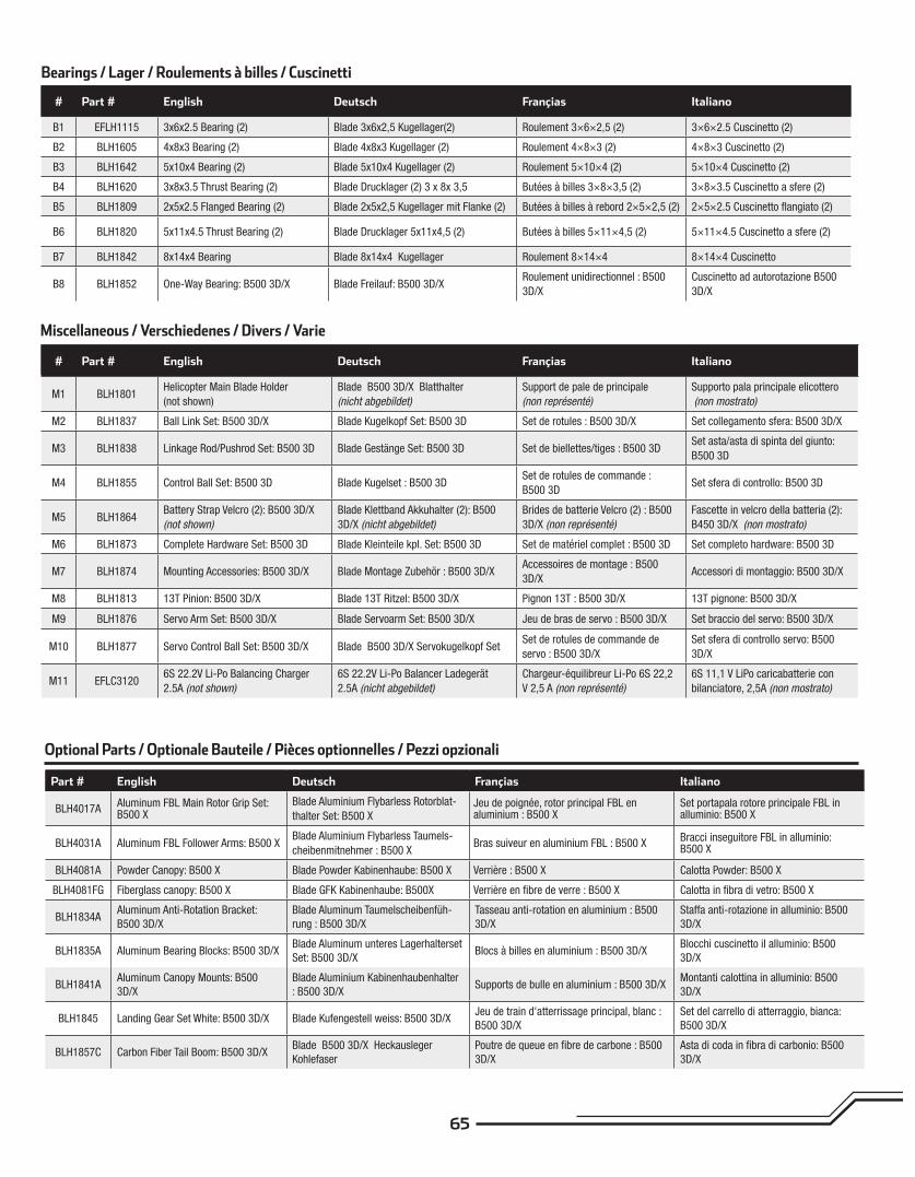
M1 BLH1801Helicopter Main Blade Holder
(not shown)
Blade B500 3D/X Blatthalter
(nicht abgebildet)
Support de pale de principale
(non représenté)
Supporto pala principale elicottero
(non mostrato)
M2 BLH1837 Ball Link Set: B500 3D/X Blade Kugelkopf Set: B500 3D Set de rotules : B500 3D/X Set collegamento sfera: B500 3D/X
M3 BLH1838 Linkage Rod/Pushrod Set: B500 3D Blade Gestänge Set: B500 3D Set de biellettes/tiges : B500 3DSet asta/asta di spinta del giunto:
B500 3D
M4 BLH1855 Control Ball Set: B500 3D Blade Kugelset : B500 3DSet de rotules de commande :
B500 3DSet sfera di controllo: B500 3D
M5 BLH1864Battery Strap Velcro (2): B500 3D/X
(not shown)
Blade Klettband Akkuhalter (2): B500
3D/X (nicht abgebildet)
Brides de batterie Velcro (2) : B500
3D/X (non représenté)
Fascette in velcro della batteria (2):
B450 3D/X (non mostrato)
M6 BLH1873 Complete Hardware Set: B500 3D Blade Kleinteile kpl. Set: B500 3D Set de matériel complet : B500 3D Set completo hardware: B500 3D
M7 BLH1874 Mounting Accessories: B500 3D/X Blade Montage Zubehör : B500 3D/XAccessoires de montage : B500
3D/XAccessori di montaggio: B500 3D/X
M8 BLH1813 13T Pinion: B500 3D/X Blade 13T Ritzel: B500 3D/X Pignon 13T : B500 3D/X 13T pignone: B500 3D/X
M9 BLH1876 Servo Arm Set: B500 3D/X Blade Servoarm Set: B500 3D/X Jeu de bras de servo : B500 3D/X Set braccio del servo: B500 3D/X
M10 BLH1877 Servo Control Ball Set: B500 3D/X Blade B500 3D/X Servokugelkopf SetSet de rotules de commande de
servo : B500 3D/X
Set sfera di controllo servo: B500
3D/X
M11 EFLC31206S 22.2V Li-Po Balancing Charger
2.5A (not shown)
6S 22.2V Li-Po Balancer Ladegerät
2.5A (nicht abgebildet)
Chargeur-équilibreur Li-Po 6S 22,2
V 2,5 A (non représenté)
6S 11,1 V LiPo caricabatterie con
bilanciatore, 2,5A (non mostrato)
# Part # English Deutsch Françias Italiano
B1 EFLH1115 3x6x2.5 Bearing (2) Blade 3x6x2,5 Kugellager(2) Roulement 3×6×2,5 (2) 3×6×2.5 Cuscinetto (2)
B2 BLH1605 4x8x3 Bearing (2) Blade 4x8x3 Kugellager (2) Roulement 4×8×3 (2) 4×8×3 Cuscinetto (2)
B3 BLH1642 5x10x4 Bearing (2) Blade 5x10x4 Kugellager (2) Roulement 5×10×4 (2) 5×10×4 Cuscinetto (2)
B4 BLH1620 3x8x3.5 Thrust Bearing (2) Blade Drucklager (2) 3 x 8x 3,5 Butées à billes 3×8×3,5 (2) 3×8×3.5 Cuscinetto a sfere (2)
B5 BLH1809 2x5x2.5 Flanged Bearing (2) Blade 2x5x2,5 Kugellager mit Flanke (2) Butées à billes à rebord 2×5×2,5 (2) 2×5×2.5 Cuscinetto fl angiato (2)
B6 BLH1820 5x11x4.5 Thrust Bearing (2) Blade Drucklager 5x11x4,5 (2) Butées à billes 5×11×4,5 (2) 5×11×4.5 Cuscinetto a sfere (2)
B7 BLH1842 8x14x4 Bearing Blade 8x14x4 Kugellager Roulement 8×14×4 8×14×4 Cuscinetto
B8 BLH1852 One-Way Bearing: B500 3D/X Blade Freilauf: B500 3D/XRoulement unidirectionnel : B500
3D/X
Cuscinetto ad autorotazione B500
3D/X
Bearings / Lager / Roulements à billes / Cuscinetti
Miscellaneous / Verschiedenes / Divers / Varie
Optional Parts / Optionale Bauteile / Pièces optionnelles / Pezzi opzionali
Part # English Deutsch Françias Italiano
BLH4017AAluminum FBL Main Rotor Grip Set: B500 X
Blade Aluminium Flybarless Rotorblat-
thalter Set: B500 XJeu de poignée, rotor principal FBL en aluminium : B500 X
Set portapala rotore principale FBL in alluminio: B500 X
BLH4031A Aluminum FBL Follower Arms: B500 XBlade Aluminium Flybarless Taumels-
cheibenmitnehmer : B500 XBras suiveur en aluminium FBL : B500 X
Bracci inseguitore FBL in alluminio: B500 X
BLH4081A Powder Canopy: B500 X Blade Powder Kabinenhaube: B500 X Verrière : B500 X Calotta Powder: B500 X
BLH4081FG Fiberglass canopy: B500 X Blade GFK Kabinenhaube: B500X Verrière en fi bre de verre : B500 X Calotta in fi bra di vetro: B500 X
BLH1834AAluminum Anti-Rotation Bracket:
B500 3D/X
Blade Aluminum Taumelscheibenfüh-
rung : B500 3D/X
Tasseau anti-rotation en aluminium : B500
3D/X
Staffa anti-rotazione in alluminio: B500
3D/X
BLH1835A Aluminum Bearing Blocks: B500 3D/XBlade Aluminum unteres Lagerhalterset
Set: B500 3D/XBlocs à billes en aluminium : B500 3D/X
Blocchi cuscinetto il alluminio: B500
3D/X
BLH1841AAluminum Canopy Mounts: B500
3D/X
Blade Aluminium Kabinenhaubenhalter
: B500 3D/XSupports de bulle en aluminium : B500 3D/X
Montanti calottina in alluminio: B500
3D/X
BLH1845 Landing Gear Set White: B500 3D/X Blade Kufengestell weiss: B500 3D/XJeu de train d'atterrissage principal, blanc :
B500 3D/X
Set del carrello di atterraggio, bianca:
B500 3D/X
BLH1857C Carbon Fiber Tail Boom: B500 3D/XBlade B500 3D/X Heckausleger
Kohlefaser
Poutre de queue en fi bre de carbone : B500
3D/X
Asta di coda in fi bra di carbonio: B500
3D/X
66
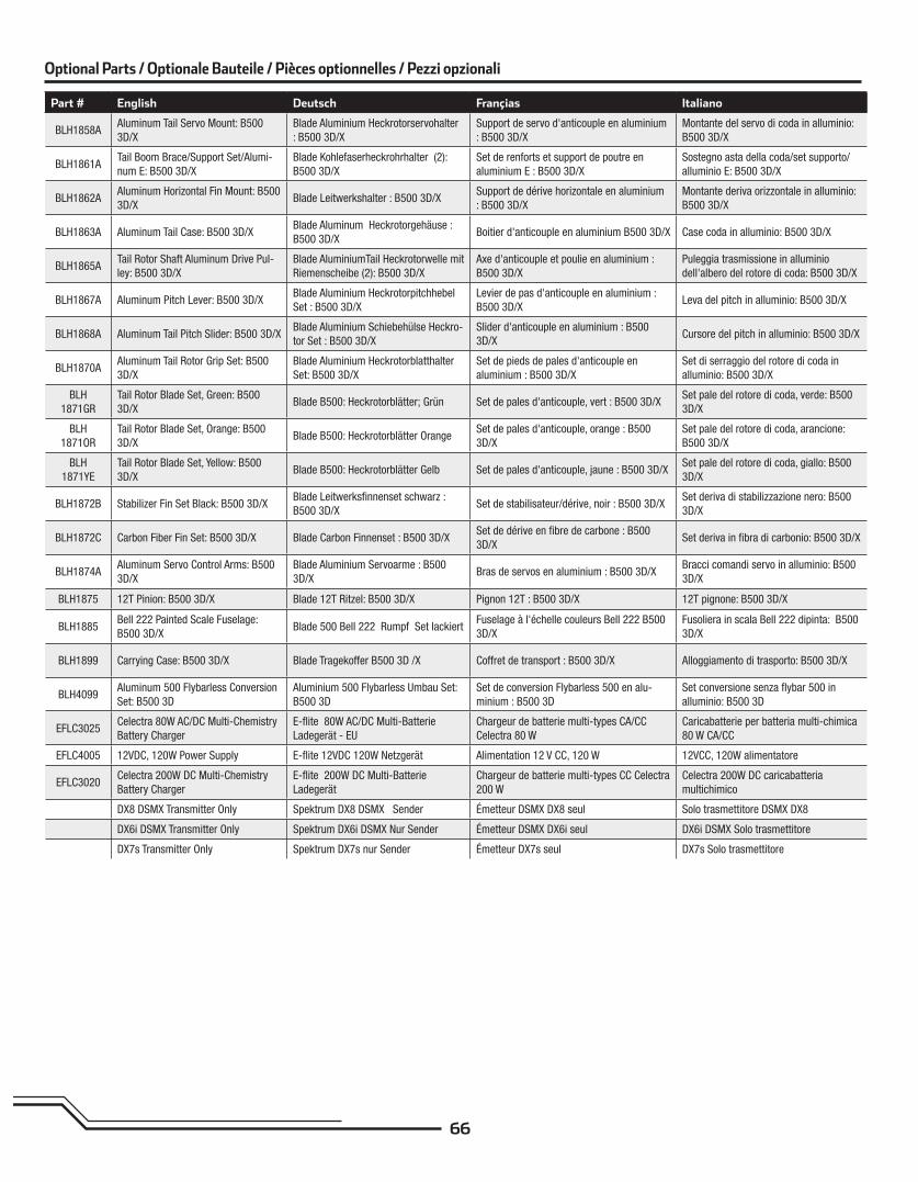
Part # English Deutsch Françias Italiano
BLH1858AAluminum Tail Servo Mount: B500
3D/X
Blade Aluminium Heckrotorservohalter
: B500 3D/X
Support de servo d'anticouple en aluminium
: B500 3D/X
Montante del servo di coda in alluminio:
B500 3D/X
BLH1861ATail Boom Brace/Support Set/Alumi-
num E: B500 3D/X
Blade Kohlefaserheckrohrhalter (2):
B500 3D/X
Set de renforts et support de poutre en
aluminium E : B500 3D/X
Sostegno asta della coda/set supporto/
alluminio E: B500 3D/X
BLH1862AAluminum Horizontal Fin Mount: B500
3D/XBlade Leitwerkshalter : B500 3D/X
Support de dérive horizontale en aluminium
: B500 3D/X
Montante deriva orizzontale in alluminio:
B500 3D/X
BLH1863A Aluminum Tail Case: B500 3D/XBlade Aluminum Heckrotorgehäuse :
B500 3D/XBoitier d'anticouple en aluminium B500 3D/X Case coda in alluminio: B500 3D/X
BLH1865ATail Rotor Shaft Aluminum Drive Pul-
ley: B500 3D/X
Blade AluminiumTail Heckrotorwelle mit
Riemenscheibe (2): B500 3D/X
Axe d'anticouple et poulie en aluminium :
B500 3D/X
Puleggia trasmissione in alluminio
dell'albero del rotore di coda: B500 3D/X
BLH1867A Aluminum Pitch Lever: B500 3D/XBlade Aluminium Heckrotorpitchhebel
Set : B500 3D/X
Levier de pas d'anticouple en aluminium :
B500 3D/XLeva del pitch in alluminio: B500 3D/X
BLH1868A Aluminum Tail Pitch Slider: B500 3D/XBlade Aluminium Schiebehülse Heckro-
tor Set : B500 3D/X
Slider d'anticouple en aluminium : B500
3D/XCursore del pitch in alluminio: B500 3D/X
BLH1870AAluminum Tail Rotor Grip Set: B500
3D/X
Blade Aluminium Heckrotorblatthalter
Set: B500 3D/X
Set de pieds de pales d'anticouple en
aluminium : B500 3D/X
Set di serraggio del rotore di coda in
alluminio: B500 3D/X
BLH
1871GR
Tail Rotor Blade Set, Green: B500
3D/XBlade B500: Heckrotorblätter; Grün Set de pales d'anticouple, vert : B500 3D/X
Set pale del rotore di coda, verde: B500
3D/X
BLH
1871OR
Tail Rotor Blade Set, Orange: B500
3D/XBlade B500: Heckrotorblätter Orange
Set de pales d'anticouple, orange : B500
3D/X
Set pale del rotore di coda, arancione:
B500 3D/X
BLH
1871YE
Tail Rotor Blade Set, Yellow: B500
3D/XBlade B500: Heckrotorblätter Gelb Set de pales d'anticouple, jaune : B500 3D/X
Set pale del rotore di coda, giallo: B500
3D/X
BLH1872B Stabilizer Fin Set Black: B500 3D/XBlade Leitwerksfi nnenset schwarz :
B500 3D/XSet de stabilisateur/dérive, noir : B500 3D/X
Set deriva di stabilizzazione nero: B500
3D/X
BLH1872C Carbon Fiber Fin Set: B500 3D/X Blade Carbon Finnenset : B500 3D/XSet de dérive en fi bre de carbone : B500
3D/XSet deriva in fi bra di carbonio: B500 3D/X
BLH1874AAluminum Servo Control Arms: B500
3D/X
Blade Aluminium Servoarme : B500
3D/XBras de servos en aluminium : B500 3D/X
Bracci comandi servo in alluminio: B500
3D/X
BLH1875 12T Pinion: B500 3D/X Blade 12T Ritzel: B500 3D/X Pignon 12T : B500 3D/X 12T pignone: B500 3D/X
BLH1885Bell 222 Painted Scale Fuselage:
B500 3D/XBlade 500 Bell 222 Rumpf Set lackiert
Fuselage à l'échelle couleurs Bell 222 B500
3D/X
Fusoliera in scala Bell 222 dipinta: B500
3D/X
BLH1899 Carrying Case: B500 3D/X Blade Tragekoffer B500 3D /X Coffret de transport : B500 3D/X Alloggiamento di trasporto: B500 3D/X
BLH4099Aluminum 500 Flybarless Conversion
Set: B500 3D
Aluminium 500 Flybarless Umbau Set:
B500 3D
Set de conversion Flybarless 500 en alu-
minium : B500 3D
Set conversione senza fl ybar 500 in
alluminio: B500 3D
EFLC3025Celectra 80W AC/DC Multi-Chemistry
Battery Charger
E-fl ite 80W AC/DC Multi-Batterie
Ladegerät - EU
Chargeur de batterie multi-types CA/CC
Celectra 80 W
Caricabatterie per batteria multi-chimica
80 W CA/CC
EFLC4005 12VDC, 120W Power Supply E-fl ite 12VDC 120W Netzgerät Alimentation 12 V CC, 120 W 12VCC, 120W alimentatore
EFLC3020Celectra 200W DC Multi-Chemistry
Battery Charger
E-fl ite 200W DC Multi-Batterie
Ladegerät
Chargeur de batterie multi-types CC Celectra
200 W
Celectra 200W DC caricabatteria
multichimico
DX8 DSMX Transmitter Only Spektrum DX8 DSMX Sender Émetteur DSMX DX8 seul Solo trasmettitore DSMX DX8
DX6i DSMX Transmitter Only Spektrum DX6i DSMX Nur Sender Émetteur DSMX DX6i seul DX6i DSMX Solo trasmettitore
DX7s Transmitter Only Spektrum DX7s nur Sender Émetteur DX7s seul DX7s Solo trasmettitore
Optional Parts / Optionale Bauteile / Pièces optionnelles / Pezzi opzionali

Instruction ManualBedienungsanleitungManuel d’utilisationManuale di Istruzioni
500 X
®
2EN
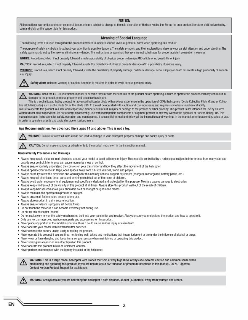
Age Recommendation: For advanced fl iers ages 14 and above. This is not a toy.
WARNING: Read the ENTIRE instruction manual to become familiar with the features of the product before operating. Failure to operate the product correctly can result in
damage to the product, personal property and cause serious injury.
This is a sophisticated hobby product for advanced helicopter pilots with previous experience in the operation of CCPM helicopters (Cyclic Collective Pitch Mixing or Collec-
tive Pitch Helicopter) such as the Blade SR or the Blade mCP X. It must be operated with caution and common sense and requires some basic mechanical ability.
Failure to operate this product in a safe and responsible manner could result in injury or damage to the product or other property. This product is not intended for use by children
without direct adult supervision. Do not attempt disassembly, use with incompatible components or augment product in any way without the approval of Horizon Hobby, Inc. This
manual contains instructions for safety, operation and maintenance. It is essential to read and follow all the instructions and warnings in the manual, prior to assembly, setup or use,
in order to operate correctly and avoid damage or serious injury.
The following terms are used throughout the product literature to indicate various levels of potential harm when operating this product:
The purpose of safety symbols is to atttract your attention to possible dangers. The safety symbols, and their explanations, deserve your careful attention and understanding. The
safety warnings do not by themselves eliminate any danger. The instructions or warnings they give are not substitutes for proper accident prevention measures.
NOTICE: Procedures, which if not properly followed, create a possibility of physical property damage AND a little or no possibility of injury.
CAUTION: Procedures, which if not properly followed, create the probability of physical property damage AND a possibility of serious injury.
WARNING: Procedures, which if not properly followed, create the probability of property damage, collateral damage, serious injury or death OR create a high probability of superfi -
cial injury.
General Safety Precautions and Warnings
• Always keep a safe distance in all directions around your model to avoid collisions or injury. This model is controlled by a radio signal subject to interference from many sources
outside your control. Interference can cause momentary loss of control.
• Always ensure you fully understand the controls on your transmitter and how they affect the movement of the helicopter.
• Always operate your model in large, open spaces away from full-size vehicles, traffi c and people.
• Always carefully follow the directions and warnings for this and any optional support equipment (chargers, rechargeable battery packs, etc.).
• Always keep all chemicals, small parts and anything electrical out of the reach of children.
• Always avoid water exposure to all equipment not specifi cally designed and protected for this purpose. Moisture causes damage to electronics.
• Always keep children out of the vicinity of this product at all times. Always store this product well out of the reach of children.
• Always keep hair secured above your shoulders so it cannot get caught in the blades.
• Always maintain and operate this product in daylight.
• Always ensure all fasteners are secure before use.
• Always store product in a dry, secure location.
• Always ensure failsafe is properly set before fl ying.
• Do not touch the motor as it can become extremely hot during use.
• Do not fl y this helicopter indoors.
• Do not exclusively rely on the safety mechanisms built into your transmitter and receiver. Always ensure you understand the product and how to operate it.
• Only use Horizon-approved replacement parts and accessories for this product.
• Never place any portion of the model in your mouth as it could cause serious injury or even death.
• Never operate your model with low transmitter batteries.
• Never connect the battery unless using or testing the product.
• Never operate this product if you are tired, not feeling well, taking any medications that impair judgment or are under the infl uence of alcohol or drugs.
• Never wear or have dangling and loose items on your person when maintaining or operating this product.
• Never spray glass cleaner or any other liquid on this product.
• Never operate this product in rain or inclement weather.
• Never perform maintenance with the battery installed in the helicopter.
NOTICEAll instructions, warranties and other collateral documents are subject to change at the sole discretion of Horizon Hobby, Inc. For up-to-date product literature, visit horizonhobby.
com and click on the support tab for this product.
Meaning of Special Language
WARNING: Failure to follow all instructions can lead to damage to your helicopter, property damage and bodily injury or death.
CAUTION: Do not make changes or adjustments to the product not shown in the instruction manual.
WARNING: This is a large model helicopter with Blades that spin at very high RPM. Always use extreme caution and common sense when
maintaining and operating this product. If you are unsure about ANY function or procedure described in this manual, DO NOT operate.
Contact Horizon Product Support for assistance.
WARNING: Always ensure you are operating the helicopter a safe distance, 45 feet (13 meters), away from yourself and others.
Safety Alert: Indicates warning or caution. Attention is required in order to avoid serious personal injury.
3 EN
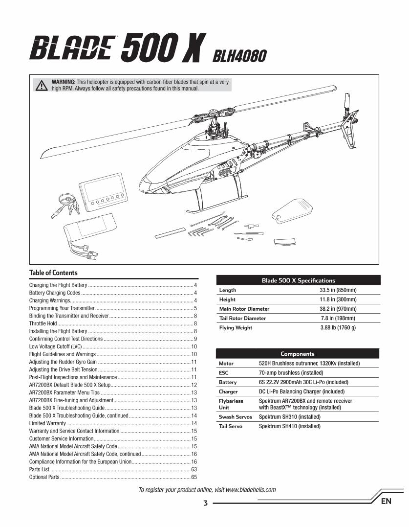
Table of ContentsBlade 500 X Specifi cations
Length 33.5 in (850mm)
Height 11.8 in (300mm)
Main Rotor Diameter 38.2 in (970mm)
Tail Rotor Diameter 7.8 in (198mm)
Flying Weight 3.88 lb (1760 g)
Components
Motor 520H Brushless outrunner, 1320Kv (installed)
ESC 70-amp brushless (installed)
Battery 6S 22.2V 2900mAh 30C Li-Po (included)
Charger DC Li-Po Balancing Charger (included)
Flybarless Unit
Spektrum AR7200BX and remote receiver with BeastX™ technology (installed)
Swash Servos Spektrum SH310 (installed)
Tail Servo Spektrum SH410 (installed)
To register your product online, visit www.bladehelis.com
Charging the Flight Battery ...........................................................................4
Battery Charging Codes ................................................................................4
Charging Warnings........................................................................................4
Programming Your Transmitter ......................................................................5
Binding the Transmitter and Receiver ............................................................8
Throttle Hold .................................................................................................8
Installing the Flight Battery ...........................................................................8
Confi rming Control Test Directions ................................................................9
Low Voltage Cutoff (LVC) .............................................................................10
Flight Guidelines and Warnings ...................................................................10
Adjusting the Rudder Gyro Gain ..................................................................11
Adjusting the Drive Belt Tension ..................................................................11
Post-Flight Inspections and Maintenance ....................................................11
AR7200BX Default Blade 500 X Setup .........................................................12
AR7200BX Parameter Menu Tips ................................................................13
AR7200BX Fine-tuning and Adjustment .......................................................13
Blade 500 X Troubleshooting Guide .............................................................13
Blade 500 X Troubleshooting Guide, continued ............................................14
Limited Warranty ........................................................................................14
Warranty and Service Contact Information ..................................................15
Customer Service Information .....................................................................15
AMA National Model Aircraft Safety Code ....................................................15
AMA National Model Aircraft Safety Code, continued ...................................16
Compliance Information for the European Union ..........................................16
Parts List ....................................................................................................63
Optional Parts .............................................................................................65
WARNING: This helicopter is equipped with carbon fi ber blades that spin at a very high RPM. Always follow all safety precautions found in this manual.
500 X BLH4080
4EN
Charging the Flight Battery
The Battery Charging Process
1. Charge only batteries that are cool to the touch and are not damaged. Make sure the battery is not swollen, bent or punctured.
2. Connect the charger to a 12V power source (minimum 10A power supply), noting proper polarity.
3. The CHARGE STATUS LED glows solid red.
4. Connect the Li-Po battery balance lead to the charger. The balance connector is keyed to prevent reverse polarity.
5. The CELL STATUS LEDs glow solid green or yellow and the CHARGE STATUS LED glows solid red when the battery is charging.
6. Battery charging is complete when all LEDs glow solid red.
7. Disconnect the battery from the charger when the charging process is complete.
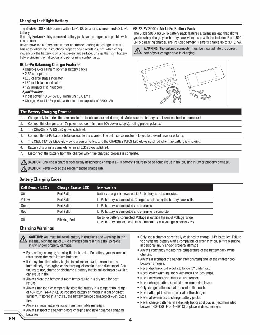
The Blade® 500 X BNF comes with a Li-Po DC balancing charger and 6S Li-Po battery. Use only Horizon Hobby approved battery packs and chargers compatible with this product. Never leave the battery and charger unattended during the charge process. Failure to follow the instructions properly could result in a fi re. When charg-ing, ensure the battery is on a heat-resistant surface. Charge the fl ight battery before binding the helicopter and performing control tests.
DC Li-Po Balancing Charger Features• Charges 6-cell lithium polymer battery packs
• 2.5A charge rate
• LED charge status indicator
• LED cell balance indicator
• 12V alligator clip input cord
Specifi cations
• Input power: 10.6–15V DC, minimum 10.0 amp
• Charges 6-cell Li-Po packs with minimum capacity of 2500mAh
6S 22.2V 2900mAh Li-Po Battery PackThe Blade 500 X 6S Li-Po battery pack features a balancing lead that allows
you to safely charge your battery pack when used with the included Blade 500
Li-Po balancing charger. The included battery is safe to charge up to 3C (8.7A).
WARNING: The balance connector must be inserted into the correct
port of your charger prior to charging!
Battery Charging Codes
Cell Status LEDs Charge Status LED Instruction
Off Red Solid Battery charger is powered. Li-Po battery is not connected.
Yellow Red Solid Li-Po battery is connected. Charger is balancing the battery pack cells
Green Red Solid Li-Po battery is connected and charging
Red Red Solid Li-Po battery is connected and charging is complete
Off Blinking RedNo Li-Po battery connected: Voltage is outside the input voltage range
Li-Po battery connected: At least one battery cell voltage is below 2.6V
CAUTION: You must follow all battery instructions and warnings in this manual. Mishandling of Li-Po batteries can result in a fi re, personal injury, and/or property damage.
• By handling, charging or using the included Li-Po battery, you assume all risks associated with lithium batteries.
• If at any time the battery begins to balloon or swell, discontinue use immediately. If charging or discharging, discontinue and disconnect. Con-tinuing to use, charge or discharge a battery that is ballooning or swelling can result in fi re.
• Always store the battery at room temperature in a dry area for best results.
• Always transport or temporarily store the battery in a temperature range of 40–120º F (4–49º C). Do not store battery or model in a car or direct sunlight. If stored in a hot car, the battery can be damaged or even catch fi re.
• Always charge batteries away from fl ammable materials.
• Always inspect the battery before charging and never charge damaged batteries.
• Only use a charger specifi cally designed to charge Li-Po batteries. Failure to charge the battery with a compatible charger may cause fi re resulting in personal injury and/or property damage
• Always constantly monitor the temperature of the battery pack while charging.
• Always disconnect the battery after charging and let the charger cool between charges.
• Never discharge Li-Po cells to below 3V under load.
• Never cover warning labels with hook and loop strips.
• Never leave charging batteries unattended.
• Never charge batteries outside recommended levels.
• Only charge batteries that are cool to the touch.
• Never attempt to dismantle or alter the charger.
• Never allow minors to charge battery packs.
• Never charge batteries in extremely hot or cold places (recommended between 40–120° F or 4–49° C) or place in direct sunlight.
Charging Warnings
CAUTION: Only use a charger specifi cally designed to charge a Li-Po battery. Failure to do so could result in fi re causing injury or property damage.
CAUTION: Never exceed the recommended charge rate.
5 EN
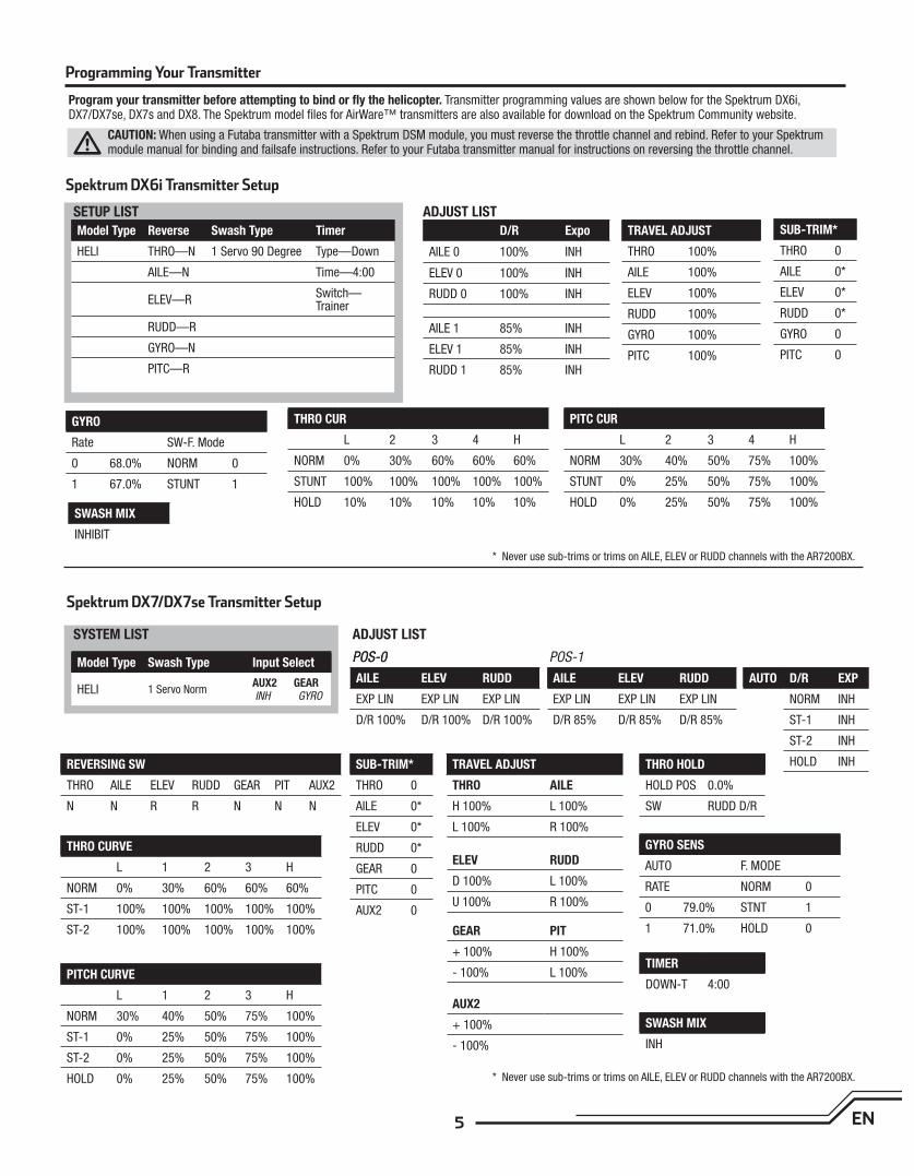
Spektrum DX6i Transmitter Setup
SETUP LIST
SYSTEM LIST
ADJUST LIST
ADJUST LIST
POS-0POS-0 POS-1
Spektrum DX7/DX7se Transmitter Setup
Model Type Reverse Swash Type Timer
HELI THRO—N 1 Servo 90 Degree Type—Down
AILE—N Time—4:00
ELEV—RSwitch—Trainer
RUDD—R
GYRO—N
PITC—R
Model Type Swash Type Input Select
HELI 1 Servo NormAUX2 GEAR INH GYRO
D/R Expo
AILE 0 100% INH
ELEV 0 100% INH
RUDD 0 100% INH
AILE 1 85% INH
ELEV 1 85% INH
RUDD 1 85% INH
AUTO D/R EXP
NORM INH
ST-1 INH
ST-2 INH
HOLD INH
AILE ELEV RUDD
EXP LIN EXP LIN EXP LIN
D/R 100% D/R 100% D/R 100%
AILE ELEV RUDD
EXP LIN EXP LIN EXP LIN
D/R 85% D/R 85% D/R 85%
TRAVEL ADJUST
THRO 100%
AILE 100%
ELEV 100%
RUDD 100%
GYRO 100%
PITC 100%
TRAVEL ADJUST
THRO AILE
H 100% L 100%
L 100% R 100%
ELEV RUDD
D 100% L 100%
U 100% R 100%
GEAR PIT
+ 100% H 100%
- 100% L 100%
AUX2
+ 100%
- 100%
SUB-TRIM*
THRO 0
AILE 0*
ELEV 0*
RUDD 0*
GYRO 0
PITC 0
SUB-TRIM*
THRO 0
AILE 0*
ELEV 0*
RUDD 0*
GEAR 0
PITC 0
AUX2 0
GYRO
Rate SW-F. Mode
0 68.0% NORM 0
1 67.0% STUNT 1
GYRO SENS
AUTO F. MODE
RATE NORM 0
0 79.0% STNT 1
1 71.0% HOLD 0
THRO HOLD
HOLD POS 0.0%
SW RUDD D/R
TIMER
DOWN-T 4:00
SWASH MIX
INH
REVERSING SW
THRO AILE ELEV RUDD GEAR PIT AUX2
N N R R N N N
THRO CUR
L 2 3 4 H
NORM 0% 30% 60% 60% 60%
STUNT 100% 100% 100% 100% 100%
HOLD 10% 10% 10% 10% 10%
THRO CURVE
L 1 2 3 H
NORM 0% 30% 60% 60% 60%
ST-1 100% 100% 100% 100% 100%
ST-2 100% 100% 100% 100% 100%
PITC CUR
L 2 3 4 H
NORM 30% 40% 50% 75% 100%
STUNT 0% 25% 50% 75% 100%
HOLD 0% 25% 50% 75% 100%
PITCH CURVE
L 1 2 3 H
NORM 30% 40% 50% 75% 100%
ST-1 0% 25% 50% 75% 100%
ST-2 0% 25% 50% 75% 100%
HOLD 0% 25% 50% 75% 100%
SWASH MIX
INHIBIT
* Never use sub-trims or trims on AILE, ELEV or RUDD channels with the AR7200BX.
* Never use sub-trims or trims on AILE, ELEV or RUDD channels with the AR7200BX.
Programming Your Transmitter
Program your transmitter before attempting to bind or fl y the helicopter. Transmitter programming values are shown below for the Spektrum DX6i, DX7/DX7se, DX7s and DX8. The Spektrum model fi les for AirWare™ transmitters are also available for download on the Spektrum Community website.
CAUTION: When using a Futaba transmitter with a Spektrum DSM module, you must reverse the throttle channel and rebind. Refer to your Spektrum module manual for binding and failsafe instructions. Refer to your Futaba transmitter manual for instructions on reversing the throttle channel.
6EN
Programming Your Transmitter
SYSTEM LIST
FUNCTION LIST
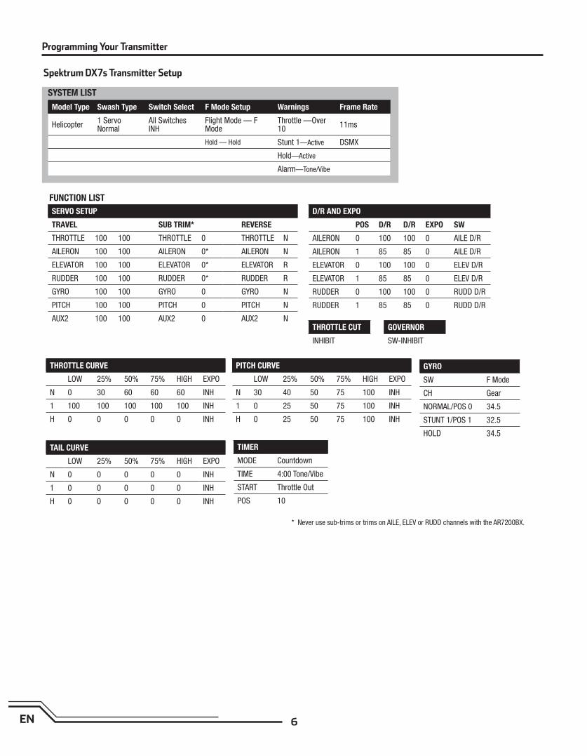
Spektrum DX7s Transmitter Setup
SERVO SETUP
TRAVEL SUB TRIM* REVERSE
THROTTLE 100 100 THROTTLE 0 THROTTLE N
AILERON 100 100 AILERON 0* AILERON N
ELEVATOR 100 100 ELEVATOR 0* ELEVATOR R
RUDDER 100 100 RUDDER 0* RUDDER R
GYRO 100 100 GYRO 0 GYRO N
PITCH 100 100 PITCH 0 PITCH N
AUX2 100 100 AUX2 0 AUX2 N
D/R AND EXPO
POS D/R D/R EXPO SW
AILERON 0 100 100 0 AILE D/R
AILERON 1 85 85 0 AILE D/R
ELEVATOR 0 100 100 0 ELEV D/R
ELEVATOR 1 85 85 0 ELEV D/R
RUDDER 0 100 100 0 RUDD D/R
RUDDER 1 85 85 0 RUDD D/R
GYRO
SW F Mode
CH Gear
NORMAL/POS 0 34.5
STUNT 1/POS 1 32.5
HOLD 34.5
TIMER
MODE Countdown
TIME 4:00 Tone/Vibe
START Throttle Out
POS 10
THROTTLE CURVE
LOW 25% 50% 75% HIGH EXPO
N 0 30 60 60 60 INH
1 100 100 100 100 100 INH
H 0 0 0 0 0 INH
TAIL CURVE
LOW 25% 50% 75% HIGH EXPO
N 0 0 0 0 0 INH
1 0 0 0 0 0 INH
H 0 0 0 0 0 INH
PITCH CURVE
LOW 25% 50% 75% HIGH EXPO
N 30 40 50 75 100 INH
1 0 25 50 75 100 INH
H 0 25 50 75 100 INH
Model Type Swash Type Switch Select F Mode Setup Warnings Frame Rate
Helicopter1 Servo Normal
All Switches INH
Flight Mode — F Mode
Throttle —Over 10
11ms
Hold — Hold Stunt 1—Active DSMX
Hold—Active
Alarm—Tone/Vibe
THROTTLE CUT
INHIBIT
GOVERNOR
SW-INHIBIT
* Never use sub-trims or trims on AILE, ELEV or RUDD channels with the AR7200BX.
7 EN
SYSTEM LIST
FUNCTION LIST
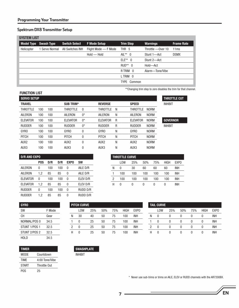
Spektrum DX8 Transmitter Setup
SERVO SETUP
TRAVEL SUB TRIM* REVERSE SPEED
THROTTLE 100 100 THROTTLE 0 THROTTLE N THROTTLE NORM
AILERON 100 100 AILERON 0* AILERON N AILERON NORM
ELEVATOR 100 100 ELEVATOR 0* ELEVATOR R ELEVATOR NORM
RUDDER 100 100 RUDDER 0* RUDDER R RUDDER NORM
GYRO 100 100 GYRO 0 GYRO N GYRO NORM
PITCH 100 100 PITCH 0 PITCH N PITCH NORM
AUX2 100 100 AUX2 0 AUX2 N AUX2 NORM
AUX3 100 100 AUX3 0 AUX3 N AUX3 NORM
D/R AND EXPO
POS D/R D/R EXPO SW
AILERON 0 100 100 0 AILE D/R
AILERON 1,2 85 85 0 AILE D/R
ELEVATOR 0 100 100 0 ELEV D/R
ELEVATOR 1,2 85 85 0 ELEV D/R
RUDDER 0 100 100 0 RUDD D/R
RUDDER 1,2 85 85 0 RUDD D/R
GYRO
SW F Mode
CH Gear
NORMAL/POS 0 34.5
STUNT 1/POS 1 32.5
STUNT 2/POS 2 32.5
HOLD 34.5
TIMER
MODE Countdown
TIME 4:00 Tone/Vibe
START Throttle Out
POS 25
THROTTLE CURVE
LOW 25% 50% 75% HIGH EXPO
N 0 30 60 60 60 INH
1 100 100 100 100 100 INH
2 100 100 100 100 100 INH
H 0 0 0 0 0 INH
TAIL CURVE
LOW 25% 50% 75% HIGH EXPO
N 0 0 0 0 0 INH
1 0 0 0 0 0 INH
2 0 0 0 0 0 INH
H 0 0 0 0 0 INH
PITCH CURVE
LOW 25% 50% 75% HIGH EXPO
N 30 40 50 75 100 INH
1 0 25 50 75 100 INH
2 0 25 50 75 100 INH
H 0 25 50 75 100 INH
Model Type Swash Type Switch Select F Mode Setup Trim Step Warnings Frame Rate
Helicopter 1 Servo Normal All Switches INH Flight Mode — F Mode THR 5 Throttle —Over 10 11ms
Hold — Hold AIL** 0 Stunt 1—Act DSMX
ELE** 0 Stunt 2—Act
RUD** 0 Hold—Act
R TRIM 0 Alarm—Tone/Vibe
L TRIM 0
TYPE Common
THROTTLE CUT
INHIBIT
SWASHPLATE
INHIBIT
GOVERNOR
INHIBIT
**Changing trim step to zero disables the trim for that channel.
* Never use sub-trims or trims on AILE, ELEV or RUDD channels with the AR7200BX.
Programming Your Transmitter
8EN
Binding is the process of programming the receiver to recognize the GUID (Globally Unique Identifi er) code of a single specifi c transmitter. You need to ‘bind’ your Spektrum™ DSM® transmitter to the fl ybarless unit before fl ying your helicopter. Please visit www.bindnfl y.com to see a list of compatible DSM transmitters.
Binding the Transmitter and Receiver
Installing the Flight Battery
Throttle Hold
When you move the throttle hold switch to the ON position, the helicopter motor turns off. You will still have control of the helicopter cyclic and rudder commands.
The blades spin if throttle hold is OFF. For safety, turn throttle hold ON any time you need to touch the helicopter or check the direction controls.
You should also turn throttle hold ON to minimize damage if the helicopter is out of control or in danger of crashing.
See your transmitter manual for more information on programming throttle hold.
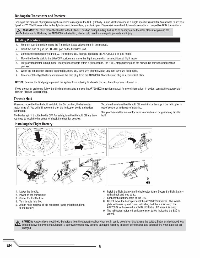
1. Lower the throttle.2. Power on the transmitter.3. Center the throttle trim.4. Turn throttle hold ON.5. Attach hook material to the helicopter frame and loop material
to the battery.
6. Install the fl ight battery on the helicopter frame. Secure the fl ight battery with a hook and loop strap.
7. Connect the battery cable to the ESC.8. Do not move the helicopter until the AR7200BX initializes. The swash-
plate will move up and down, indicating that the unit is ready. The AR7200BX will also emit a solid BLUE Status LED when it is ready
9. The helicopter motor will emit a series of tones, indicating the ESC is armed.
Binding Procedure
1. Program your transmitter using the Transmitter Setup values found in this manual.
2. Insert the bind plug in the BND/DAT port on the fl ybarless unit.
3. Connect the fl ight battery to the ESC. The H menu LED fl ashes, indicating the AR7200BX is in bind mode.
4. Move the throttle stick to the LOW/OFF position and move the fl ight mode switch to select Normal fl ight mode.
5. Put your transmitter in bind mode. The system connects within a few seconds. The H LED stops fl ashing and the AR7200BX starts the initialization
process.
6. When the initialization process is complete, menu LED turns OFF and the Status LED light turns ON solid BLUE.
7. Disconnect the fl ight battery and remove the bind plug from the AR7200BX. Store the bind plug in a convenient place.
WARNING: You must move the throttle to the LOW/OFF position during binding. Failure to do so may cause the rotor blades to spin and the helicopter to lift during the AR7200BX initialization, which could result in damage to property and injury.
NOTICE: Remove the bind plug to prevent the system from entering bind mode the next time the power is turned on.
If you encounter problems, follow the binding instructions and see the AR7200BX instruction manual for more information. If needed, contact the appropriate Horizon Product Support offi ce.
CAUTION: Always disconnect the Li-Po battery from the aircraft receiver when not in use to avoid over-discharging the battery. Batteries discharged to a voltage below the lowest manufacturer’s approved voltage may become damaged, resulting in loss of performance and potential fi re when batteries are charged.
9 EN
Rudder Gyro Test 1. Power on the transmitter.
2. Turn throttle hold ON and move the fl ight mode switch to select Normal fl ight mode.
3. Connect the Li-Po battery to the ESC.
NOTICE: Do not allow the helicopter to move until the Status LED is solid blue and all menu LEDs are OFF. The gyro will not operate correctly if the helicopter moves before the Status LED is solid blue.
4. Move the rudder stick to the right. The tail rotor blades move as shown. If they do not move as shown, reverse the rudder channel in your trans-mitter.
5. Release the rudder control.
6. Manually turn the helicopter nose to the left. The tail rotor blades automatically move as shown. If they do not move as shown, reverse the AR7200BX tail sensor direc-tion (Setup menu point F). See the AR7200BX instruction manual for more information.
Cyclic Gyro Test
When using a fl ybarless system, you are controlling rotational rates while the AR7200BX controls the servos. You are not directly controlling the servos with the transmitter.
It is normal for the swashplate to slowly move back to its original position after a stick input and for the servos to not move at the same speed as your control sticks.
1. Tilt the helicopter forward. The swashplate should tilt backward.
2. Tilt the helicopter backward. The swashplate should tilt forward.
3. Roll the helicopter left. The swashplate should roll right.
4. Roll the helicopter right. The swashplate should roll left.
5. If the swashplate does not move in the correct direction, you will need to reverse the cyclic sensor direction. Refer to the AR7200BX manual for more information (Setup menu point M).
6. Disconnect the fl ight battery from the ESC.
7. Power the transmitter OFF.
8. Connect the motor wires to the ESC.
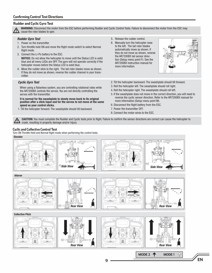
Confi rming Control Test Directions
Cyclic and Collective Control TestTurn ON Throttle Hold and Normal fl ight mode when performing the control tests.
Rudder and Cyclic Gyro Test
MODE 2 MODE 1
Elevator
Side View Side View
Aileron
Rear ViewRear View
Collective Pitch
Rear ViewRear View
CAUTION: You must complete the Rudder and Cyclic tests prior to fl ight. Failure to confi rm the sensor directions are correct can cause the helicopter to crash, resulting in property damage and/or injury.
WARNING: Disconnect the motor from the ESC before performing Rudder and Cyclic Control Tests. Failure to disconnect the motor from the ESC may cause the rotor blades to spin.
10EN
Motor Control Test
Place the helicopter outdoors on a clean, fl at and level surface (concrete or asphalt) free of obstructions. Always stay clear of moving rotor blades.
1 Power on the transmitter. Make sure throttle hold is ON and the fl ight mode switch is in the normal position.
WARNING: The motor will spin when throttle is increased and TH HOLD is OFF.
2. Lower the throttle completely.
WARNING: Stay at least 45 feet (13 meters) away from the helicopter when the motor is running. Do not attempt to fl y the helicopter at this time.
3. Connect the Li-Po battery to the ESC.
4. Turn throttle hold OFF. Slowly increase the throttle until the blades begin to spin. The main blades spin clockwise when viewing the helicopter from the top. The tail rotor blades spin counterclockwise when viewing the helicopter from the right-hand side.
NOTICE: If the main rotor blades are spinning counterclockwise, make sure you are in normal mode and reduce the throttle to low immediately. Turn TH HOLD ON. Disconnect the battery from the helicopter and reverse any two motor wire connections to the ESC and repeat the motor control test.
Consult local laws and ordinances before choosing a location to fl y your aircraft.
Select a large, open area away from people and objects. Your fi rst fl ights should be outdoors in low-wind conditions. Always stay at least 45 feet (13 meters) away from the helicopter when it is fl ying.
Do not attempt to fl y the Blade 500 X indoors.
CAUTION: The Blade 500 X is intended for pilots with experience fl ying
aerobatic, collective pitch helicopters. The Blade 500 X is more respon-
sive than other Blade helicopters. If you are not an experienced 3D or
collective pitch helicopter pilot, do not attempt to fl y this product.
Takeoff
Deliberately increase throttle and establish a hover at least 36” (1 meter) high, outside of ground effect.
CAUTION: Do not give any aileron, elevator or rudder commands before takeoff or the helicopter may crash.
Flying
The helicopter lifts off the ground when the rotor head reaches a suitable speed. Establish a low-level hover to verify proper operation of your helicopter. You must not set any trim; the fl ybarless design of the Blade 500 X renders trim unnecessary. Setting trim or sub-trim can cause an unwanted drift or rota-tion of the helicopter.
First fl ights should be performed in normal mode with low cyclic and rudder dual rates until you are familiar with the fl ying manner of the Blade 500 X. Discover the rates that fi t your fl ying style.
CAUTION: Always fl y the helicopter with your back to the sun and wind to prevent loss of fl ight control.
Landing
Establish a low level hover. Deliberately lower the throttle until the helicopter lands. Do not give any aileron, elevator or rudder commands when the helicop-ter is landing.
When the helicopter is in stunt mode:
- The rotor head speed is constant. - The main rotor will increase negative pitch as the throttle/collective stick is moved from the middle stick position to the low stick position. Negative pitch allows the helicopter to fl y upside down and perform aerobatics.
Change between stunt and idle up modes in a hover with the throttle near the hovering stick position.
The helicopter may go up or down when you change between modes due to the difference in the throttle and pitch curves.
WARNING: Only use Blade 500 X approved carbon fi ber main blades. Do not use wooden main blades with the Blade 500 X. Using wooden main blades may cause injury or property damage.
If the cyclic control is too slow or too fast, adjust the transmitter dual rates, expo or throttle curve to fi t your liking.
Flight Guidelines and Warnings
• Always keep aircraft in sight and under control.
• Always keep people and pets at least 45 feet (13 meters) away when the battery is connected.
• Keep children out of the vicinity of this product at all times.
• Always turn on throttle hold at rotor strike.
• Always use fullly charged batteries.
• Always keep transmitter powered on while aircraft is powered.
• Always remove batteries before disassembly.
• Always keep moving parts clean.
• Always keep parts dry.
• Always let parts cool after use before touching.
• Always remove batteries after use.
• Always have a fi rst aid kit with you.
• Always have an appropriate fi re extinguisher with you.
• Never operate aircraft with damaged wiring.
• Never touch moving parts.
Low Voltage Cutoff (LVC)
Low voltage cutoff (LVC) protects the Li-Po battery from overdischarge in fl ight and activates when the battery reaches 3V per cell under load.
Set your transmitter timer for 4 minutes and land when the timer expires.
Repeatedly activating LVC damages the fl ight battery and you will need to replace the battery.
Crash damage and battery damage are not covered under warranty.
11 EN
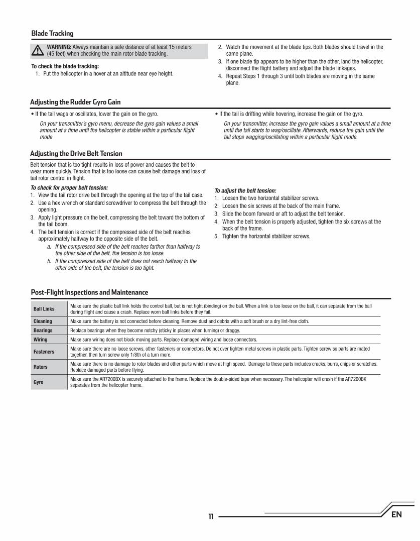
Adjusting the Rudder Gyro Gain
• If the tail wags or oscillates, lower the gain on the gyro.
On your transmitter’s gyro menu, decrease the gyro gain values a small amount at a time until the helicopter is stable within a particular fl ight mode
• If the tail is drifting while hovering, increase the gain on the gyro.
On your transmitter, increase the gyro gain values a small amount at a time until the tail starts to wag/oscillate. Afterwards, reduce the gain until the tail stops wagging/oscillating within a particular fl ight mode.
Post-Flight Inspections and Maintenance
Ball LinksMake sure the plastic ball link holds the control ball, but is not tight (binding) on the ball. When a link is too loose on the ball, it can separate from the ball during fl ight and cause a crash. Replace worn ball links before they fail.
Cleaning Make sure the battery is not connected before cleaning. Remove dust and debris with a soft brush or a dry lint-free cloth.
Bearings Replace bearings when they become notchy (sticky in places when turning) or draggy.
Wiring Make sure wiring does not block moving parts. Replace damaged wiring and loose connectors.
FastenersMake sure there are no loose screws, other fasteners or connectors. Do not over tighten metal screws in plastic parts. Tighten screw so parts are mated together, then turn screw only 1/8th of a turn more.
RotorsMake sure there is no damage to rotor blades and other parts which move at high speed. Damage to these parts includes cracks, burrs, chips or scratches. Replace damaged parts before fl ying.
GyroMake sure the AR7200BX is securely attached to the frame. Replace the double-sided tape when necessary. The helicopter will crash if the AR7200BX separates from the helicopter frame.
Adjusting the Drive Belt Tension
Belt tension that is too tight results in loss of power and causes the belt to wear more quickly. Tension that is too loose can cause belt damage and loss of tail rotor control in fl ight.
To check for proper belt tension:
1. View the tail rotor drive belt through the opening at the top of the tail case.
2. Use a hex wrench or standard screwdriver to compress the belt through the opening.
3. Apply light pressure on the belt, compressing the belt toward the bottom of the tail boom.
4. The belt tension is correct if the compressed side of the belt reaches approximately halfway to the opposite side of the belt.
a. If the compressed side of the belt reaches farther than halfway to the other side of the belt, the tension is too loose.
b. If the compressed side of the belt does not reach halfway to the other side of the belt, the tension is too tight.
To adjust the belt tension:
1. Loosen the two horizontal stabilizer screws.
2. Loosen the six screws at the back of the main frame.
3. Slide the boom forward or aft to adjust the belt tension.
4. When the belt tension is properly adjusted, tighten the six screws at the back of the frame.
5. Tighten the horizontal stabilizer screws.
Blade Tracking
WARNING: Always maintain a safe distance of at least 15 meters (45 feet) when checking the main rotor blade tracking.
To check the blade tracking:
1. Put the helicopter in a hover at an altitude near eye height.
2. Watch the movement at the blade tips. Both blades should travel in the same plane.
3. If one blade tip appears to be higher than the other, land the helicopter, disconnect the fl ight battery and adjust the blade linkages.
4. Repeat Steps 1 through 3 until both blades are moving in the same plane.
12EN
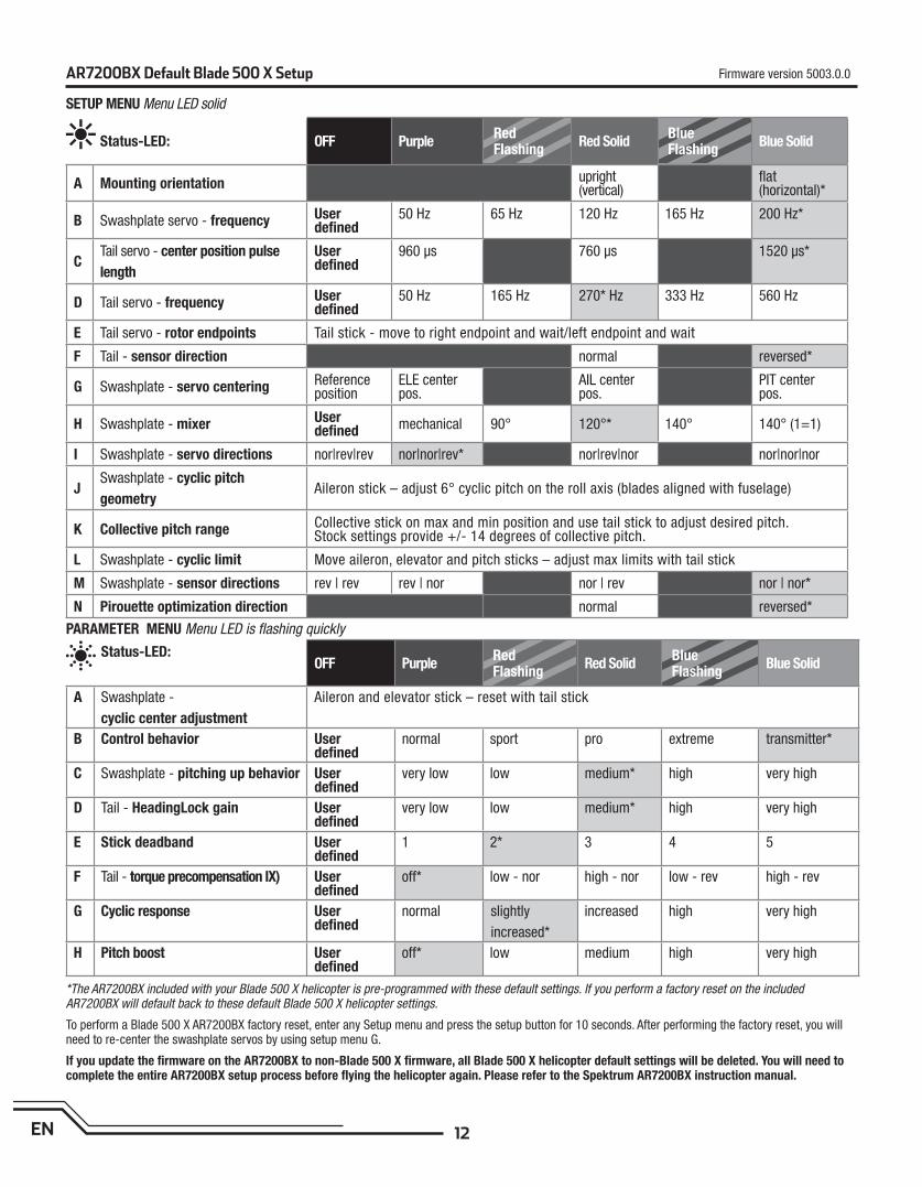
AR7200BX Default Blade 500 X Setup
*The AR7200BX included with your Blade 500 X helicopter is pre-programmed with these default settings. If you perform a factory reset on the included AR7200BX will default back to these default Blade 500 X helicopter settings.
To perform a Blade 500 X AR7200BX factory reset, enter any Setup menu and press the setup button for 10 seconds. After performing the factory reset, you will need to re-center the swashplate servos by using setup menu G.
If you update the fi rmware on the AR7200BX to non-Blade 500 X fi rmware, all Blade 500 X helicopter default settings will be deleted. You will need to complete the entire AR7200BX setup process before fl ying the helicopter again. Please refer to the Spektrum AR7200BX instruction manual.
Status-LED: OFF PurpleRed Flashing
Red SolidBlue Flashing
Blue Solid
A Mounting orientation upright (vertical)
fl at (horizontal)*
B Swashplate servo - frequency User defi ned
50 Hz 65 Hz 120 Hz 165 Hz 200 Hz*
CTail servo - center position pulse
length
User defi ned
960 μs 760 μs 1520 μs*
D Tail servo - frequency User defi ned
50 Hz 165 Hz 270* Hz 333 Hz 560 Hz
E Tail servo - rotor endpoints Tail stick - move to right endpoint and wait/left endpoint and wait
F Tail - sensor direction normal reversed*
G Swashplate - servo centering Reference position
ELE center pos.
AIL center pos.
PIT center pos.
H Swashplate - mixer User defi ned mechanical 90° 120°* 140° 140° (1=1)
I Swashplate - servo directions nor|rev|rev nor|nor|rev* nor|rev|nor nor|nor|nor
JSwashplate - cyclic pitch
geometryAileron stick – adjust 6° cyclic pitch on the roll axis (blades aligned with fuselage)
K Collective pitch range Collective stick on max and min position and use tail stick to adjust desired pitch. Stock settings provide +/- 14 degrees of collective pitch.
L Swashplate - cyclic limit Move aileron, elevator and pitch sticks – adjust max limits with tail stick
M Swashplate - sensor directions rev | rev rev | nor nor | rev nor | nor*
N Pirouette optimization direction normal reversed*
Status-LED: OFF Purple
Red Flashing
Red SolidBlue Flashing
Blue Solid
A Swashplate -
cyclic center adjustment
Aileron and elevator stick – reset with tail stick
B Control behavior User defi ned
normal sport pro extreme transmitter*
C Swashplate - pitching up behavior User defi ned
very low low medium* high very high
D Tail - HeadingLock gain User defi ned
very low low medium* high very high
E Stick deadband User defi ned
1 2* 3 4 5
F Tail - torque precompensation IX) User defi ned
off* low - nor high - nor low - rev high - rev
G Cyclic response User defi ned
normal slightly
increased*
increased high very high
H Pitch boost User defi ned
off* low medium high very high
PARAMETER MENU Menu LED is fl ashing quickly
SETUP MENU Menu LED solid
Firmware version 5003.0.0
13 EN
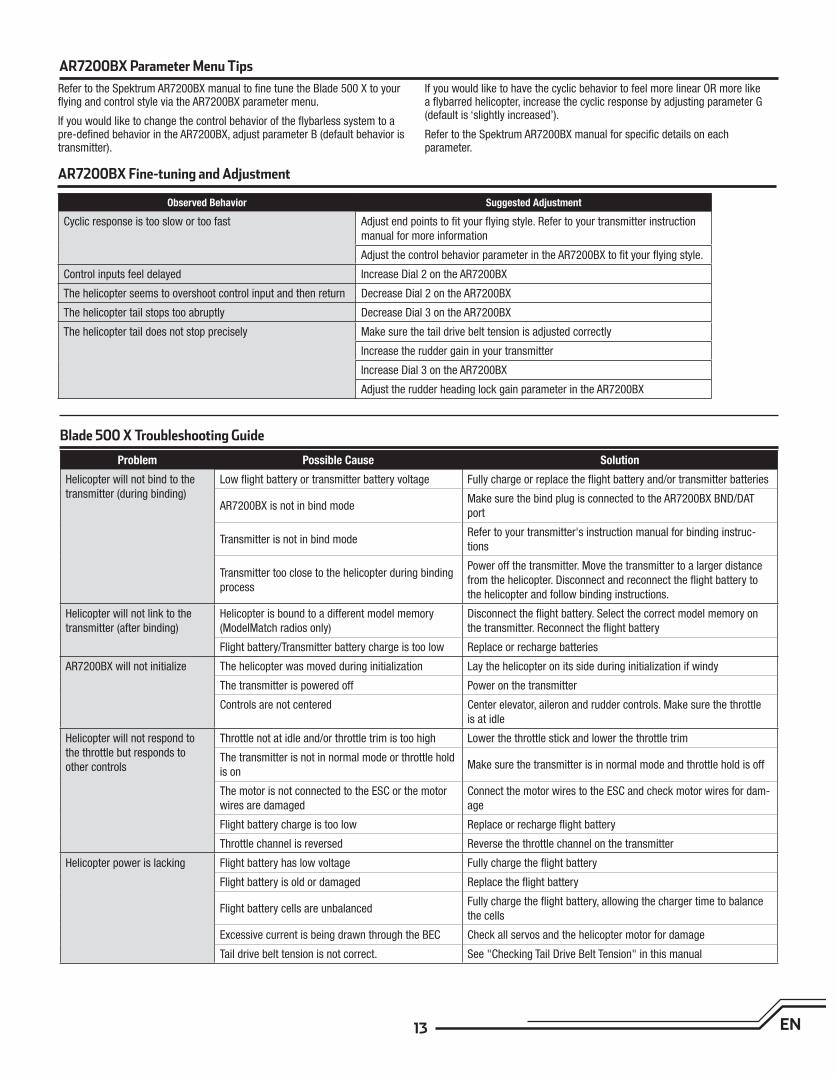
AR7200BX Fine-tuning and Adjustment
Blade 500 X Troubleshooting Guide
Problem Possible Cause Solution
Helicopter will not bind to the
transmitter (during binding)
Low fl ight battery or transmitter battery voltage Fully charge or replace the fl ight battery and/or transmitter batteries
AR7200BX is not in bind modeMake sure the bind plug is connected to the AR7200BX BND/DAT
port
Transmitter is not in bind modeRefer to your transmitter's instruction manual for binding instruc-
tions
Transmitter too close to the helicopter during binding
process
Power off the transmitter. Move the transmitter to a larger distance
from the helicopter. Disconnect and reconnect the fl ight battery to
the helicopter and follow binding instructions.
Helicopter will not link to the
transmitter (after binding)
Helicopter is bound to a different model memory
(ModelMatch radios only)
Disconnect the fl ight battery. Select the correct model memory on
the transmitter. Reconnect the fl ight battery
Flight battery/Transmitter battery charge is too low Replace or recharge batteries
AR7200BX will not initialize The helicopter was moved during initialization Lay the helicopter on its side during initialization if windy
The transmitter is powered off Power on the transmitter
Controls are not centered Center elevator, aileron and rudder controls. Make sure the throttle
is at idle
Helicopter will not respond to
the throttle but responds to
other controls
Throttle not at idle and/or throttle trim is too high Lower the throttle stick and lower the throttle trim
The transmitter is not in normal mode or throttle hold
is onMake sure the transmitter is in normal mode and throttle hold is off
The motor is not connected to the ESC or the motor
wires are damaged
Connect the motor wires to the ESC and check motor wires for dam-
age
Flight battery charge is too low Replace or recharge fl ight battery
Throttle channel is reversed Reverse the throttle channel on the transmitter
Helicopter power is lacking Flight battery has low voltage Fully charge the fl ight battery
Flight battery is old or damaged Replace the fl ight battery
Flight battery cells are unbalancedFully charge the fl ight battery, allowing the charger time to balance
the cells
Excessive current is being drawn through the BEC Check all servos and the helicopter motor for damage
Tail drive belt tension is not correct. See "Checking Tail Drive Belt Tension" in this manual
AR7200BX Parameter Menu Tips
Refer to the Spektrum AR7200BX manual to fi ne tune the Blade 500 X to your fl ying and control style via the AR7200BX parameter menu.
If you would like to change the control behavior of the fl ybarless system to a pre-defi ned behavior in the AR7200BX, adjust parameter B (default behavior is transmitter).
If you would like to have the cyclic behavior to feel more linear OR more like a fl ybarred helicopter, increase the cyclic response by adjusting parameter G (default is ‘slightly increased’).
Refer to the Spektrum AR7200BX manual for specifi c details on eachparameter.
Observed Behavior Suggested Adjustment
Cyclic response is too slow or too fast Adjust end points to fi t your fl ying style. Refer to your transmitter instruction
manual for more information
Adjust the control behavior parameter in the AR7200BX to fi t your fl ying style.
Control inputs feel delayed Increase Dial 2 on the AR7200BX
The helicopter seems to overshoot control input and then return Decrease Dial 2 on the AR7200BX
The helicopter tail stops too abruptly Decrease Dial 3 on the AR7200BX
The helicopter tail does not stop precisely Make sure the tail drive belt tension is adjusted correctly
Increase the rudder gain in your transmitter
Increase Dial 3 on the AR7200BX
Adjust the rudder heading lock gain parameter in the AR7200BX
14EN
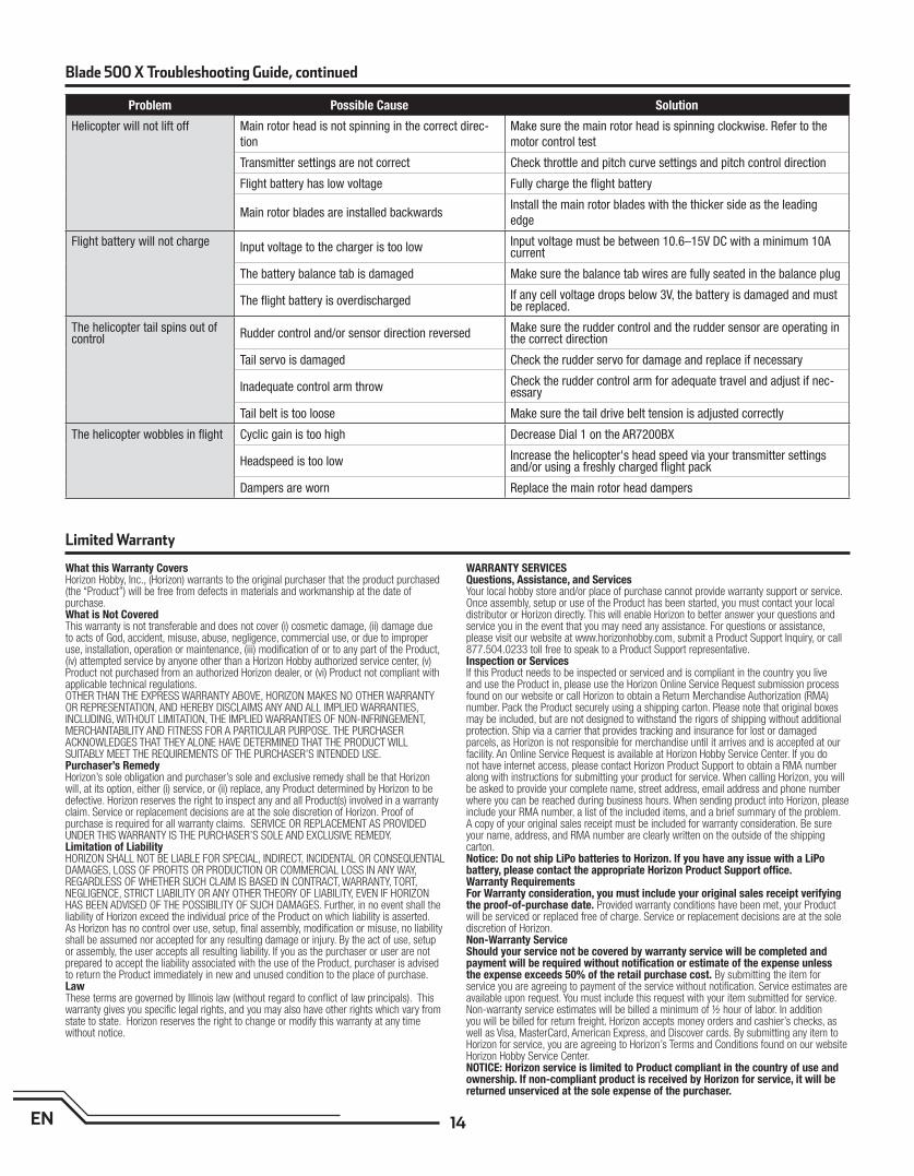
What this Warranty CoversHorizon Hobby, Inc., (Horizon) warrants to the original purchaser that the product purchased (the “Product”) will be free from defects in materials and workmanship at the date of purchase.What is Not CoveredThis warranty is not transferable and does not cover (i) cosmetic damage, (ii) damage due to acts of God, accident, misuse, abuse, negligence, commercial use, or due to improper use, installation, operation or maintenance, (iii) modifi cation of or to any part of the Product, (iv) attempted service by anyone other than a Horizon Hobby authorized service center, (v) Product not purchased from an authorized Horizon dealer, or (vi) Product not compliant with applicable technical regulations. OTHER THAN THE EXPRESS WARRANTY ABOVE, HORIZON MAKES NO OTHER WARRANTY OR REPRESENTATION, AND HEREBY DISCLAIMS ANY AND ALL IMPLIED WARRANTIES, INCLUDING, WITHOUT LIMITATION, THE IMPLIED WARRANTIES OF NON-INFRINGEMENT, MERCHANTABILITY AND FITNESS FOR A PARTICULAR PURPOSE. THE PURCHASER ACKNOWLEDGES THAT THEY ALONE HAVE DETERMINED THAT THE PRODUCT WILL SUITABLY MEET THE REQUIREMENTS OF THE PURCHASER’S INTENDED USE. Purchaser’s RemedyHorizon’s sole obligation and purchaser’s sole and exclusive remedy shall be that Horizon will, at its option, either (i) service, or (ii) replace, any Product determined by Horizon to be defective. Horizon reserves the right to inspect any and all Product(s) involved in a warranty claim. Service or replacement decisions are at the sole discretion of Horizon. Proof of purchase is required for all warranty claims. SERVICE OR REPLACEMENT AS PROVIDED UNDER THIS WARRANTY IS THE PURCHASER’S SOLE AND EXCLUSIVE REMEDY. Limitation of LiabilityHORIZON SHALL NOT BE LIABLE FOR SPECIAL, INDIRECT, INCIDENTAL OR CONSEQUENTIAL DAMAGES, LOSS OF PROFITS OR PRODUCTION OR COMMERCIAL LOSS IN ANY WAY, REGARDLESS OF WHETHER SUCH CLAIM IS BASED IN CONTRACT, WARRANTY, TORT, NEGLIGENCE, STRICT LIABILITY OR ANY OTHER THEORY OF LIABILITY, EVEN IF HORIZON HAS BEEN ADVISED OF THE POSSIBILITY OF SUCH DAMAGES. Further, in no event shall the liability of Horizon exceed the individual price of the Product on which liability is asserted. As Horizon has no control over use, setup, fi nal assembly, modifi cation or misuse, no liability shall be assumed nor accepted for any resulting damage or injury. By the act of use, setup or assembly, the user accepts all resulting liability. If you as the purchaser or user are not prepared to accept the liability associated with the use of the Product, purchaser is advised to return the Product immediately in new and unused condition to the place of purchase.LawThese terms are governed by Illinois law (without regard to confl ict of law principals). This warranty gives you specifi c legal rights, and you may also have other rights which vary from state to state. Horizon reserves the right to change or modify this warranty at any time without notice.
WARRANTY SERVICESQuestions, Assistance, and ServicesYour local hobby store and/or place of purchase cannot provide warranty support or service. Once assembly, setup or use of the Product has been started, you must contact your local distributor or Horizon directly. This will enable Horizon to better answer your questions and service you in the event that you may need any assistance. For questions or assistance, please visit our website at www.horizonhobby.com, submit a Product Support Inquiry, or call 877.504.0233 toll free to speak to a Product Support representative. Inspection or ServicesIf this Product needs to be inspected or serviced and is compliant in the country you live and use the Product in, please use the Horizon Online Service Request submission process found on our website or call Horizon to obtain a Return Merchandise Authorization (RMA) number. Pack the Product securely using a shipping carton. Please note that original boxes may be included, but are not designed to withstand the rigors of shipping without additional protection. Ship via a carrier that provides tracking and insurance for lost or damaged parcels, as Horizon is not responsible for merchandise until it arrives and is accepted at our facility. An Online Service Request is available at Horizon Hobby Service Center. If you do not have internet access, please contact Horizon Product Support to obtain a RMA number along with instructions for submitting your product for service. When calling Horizon, you will be asked to provide your complete name, street address, email address and phone number where you can be reached during business hours. When sending product into Horizon, please include your RMA number, a list of the included items, and a brief summary of the problem. A copy of your original sales receipt must be included for warranty consideration. Be sure your name, address, and RMA number are clearly written on the outside of the shipping carton. Notice: Do not ship LiPo batteries to Horizon. If you have any issue with a LiPo battery, please contact the appropriate Horizon Product Support offi ce.Warranty Requirements For Warranty consideration, you must include your original sales receipt verifying the proof-of-purchase date. Provided warranty conditions have been met, your Product will be serviced or replaced free of charge. Service or replacement decisions are at the sole discretion of Horizon.Non-Warranty ServiceShould your service not be covered by warranty service will be completed and payment will be required without notifi cation or estimate of the expense unless the expense exceeds 50% of the retail purchase cost. By submitting the item for service you are agreeing to payment of the service without notifi cation. Service estimates are available upon request. You must include this request with your item submitted for service. Non-warranty service estimates will be billed a minimum of ½ hour of labor. In addition you will be billed for return freight. Horizon accepts money orders and cashier’s checks, as well as Visa, MasterCard, American Express, and Discover cards. By submitting any item to Horizon for service, you are agreeing to Horizon’s Terms and Conditions found on our website Horizon Hobby Service Center. NOTICE: Horizon service is limited to Product compliant in the country of use and ownership. If non-compliant product is received by Horizon for service, it will be returned unserviced at the sole expense of the purchaser.
Limited Warranty
Problem Possible Cause Solution
Helicopter will not lift off Main rotor head is not spinning in the correct direc-
tion
Make sure the main rotor head is spinning clockwise. Refer to the
motor control test
Transmitter settings are not correct Check throttle and pitch curve settings and pitch control direction
Flight battery has low voltage Fully charge the fl ight battery
Main rotor blades are installed backwardsInstall the main rotor blades with the thicker side as the leading
edge
Flight battery will not charge Input voltage to the charger is too low Input voltage must be between 10.6–15V DC with a minimum 10A current
The battery balance tab is damaged Make sure the balance tab wires are fully seated in the balance plug
The fl ight battery is overdischarged If any cell voltage drops below 3V, the battery is damaged and must be replaced.
The helicopter tail spins out of control Rudder control and/or sensor direction reversed Make sure the rudder control and the rudder sensor are operating in
the correct direction
Tail servo is damaged Check the rudder servo for damage and replace if necessary
Inadequate control arm throw Check the rudder control arm for adequate travel and adjust if nec-essary
Tail belt is too loose Make sure the tail drive belt tension is adjusted correctly
The helicopter wobbles in fl ight Cyclic gain is too high Decrease Dial 1 on the AR7200BX
Headspeed is too low Increase the helicopter's head speed via your transmitter settings and/or using a freshly charged fl ight pack
Dampers are worn Replace the main rotor head dampers
Blade 500 X Troubleshooting Guide, continued
15 EN
Warranty and Service Contact Information
AMA National Model Aircraft Safety Code
Country of Purchase Horizon Hobby Address Phone Number / Email Address
United States of America
Horizon Service Center(Electronics and engines)
4105 Fieldstone RdChampaign, Illinois, 61822 USA
877-504-0233Online Repair Request visit: www.horizonhobby.com/service
Horizon Product Support(All other products)
4105 Fieldstone RdChampaign, Illinois, 61822 USA
United Kingdom Horizon Hobby LimitedUnits 1-4 Ployters RdStaple TyeHarlow, Essex, CM18 7NS, United Kingdom
+44 (0) 1279 641 [email protected]
Germany Horizon Technischer ServiceChristian-Junge-Straße 1 25337 Elmshorn, Germany
+49 (0) 4121 2655 [email protected]
France Horizon Hobby SAS14 Rue Gustave EiffelZone d’Activité du Réveil Matin91230 Montgeron
+33 (0) 1 60 47 44 [email protected]
China Horizon Hobby – ChinaRoom 506, No. 97 Changshou Rd.
Shanghai, China 200060
+86 (021) 5180 9868
Customer Service Information
Country of Purchase Horizon Hobby Address Phone Number / Email Address
United StatesSales
4105 Fieldstone RdChampaign, Illinois, 61822 USA
(800) [email protected]
United Kingdom Horizon Hobby LimitedUnits 1-4 Ployters RdStaple TyeHarlow, Essex, CM18 7NS, United Kingdom
+44 (0) 1279 641 [email protected]
Germany Horizon Hobby GmbHChristian-Junge-Straße 1 25337 Elmshorn, Germany
+49 (0) 4121 2655 [email protected]
France Horizon Hobby SAS14 Rue Gustave EiffelZone d’Activité du Réveil Matin91230 Montgeron
+33 (0) 1 60 47 44 [email protected]
China Horizon Hobby – ChinaRoom 506, No. 97 Changshou Rd. Shanghai, China 200060
+86 (021) 5180 [email protected]
Effective January 1, 2011
A. GENERAL: A model aircraft is a non-human-carrying aircraft capable of sustained fl ight
in the atmosphere. It may not exceed limitations of this code and is intended exclusively
for sport, recreation and/or competition. All model fl ights must be conducted in accor-
dance with this safety code and any additional rules specifi c to the fl ying site.
1. Model aircraft will not be fl own:
(a) In a careless or reckless manner.
(b) At a location where model aircraft activities are prohibited.
2. Model aircraft pilots will:
(a) Yield the right of way to all man carrying aircraft.
(b) See and avoid all aircraft and a spotter must be used when appropriate. (AMA
Document #540-D-See and Avoid Guidance.)
(c) Not fl y higher than approximately 400 feet above ground level within three (3)
miles of an airport, without notifying the airport operator.
(d) Not interfere with operations and traffi c patterns at any airport, heliport or
seaplane base except where there is a mixed use agreement.
(e) Not exceed a takeoff weight, including fuel, of 55 pounds unless in compliance
with the AMA Large Model Aircraft program. (AMA Document 520-A)
(f) Ensure the aircraft is identifi ed with the name and address or AMA number of the
owner on the inside or affi xed to the outside of the model aircraft. (This does not
apply to model aircraft fl own indoors).
(g) Not operate aircraft with metal-blade propellers or with gaseous boosts except
for helicopters operated under the provisions of AMA Document #555.
(h) Not operate model aircraft while under the infl uence of alcohol or while using
any drug which could adversely affect the pilot’s ability to safely control the
model.
(i) Not operate model aircraft carrying pyrotechnic devices which explode or burn, or
any device which propels a projectile or drops any object that creates a hazard
to persons or property.
Exceptions:
• Free Flight fuses or devices that burn producing smoke and are securely
attached to the model aircraft during fl ight.
• Rocket motors (using solid propellant) up to a G-series size may be used
provided they remain attached to the model during fl ight. Model rockets
may be fl own in accordance with the National Model Rocketry Safety
Code but may not be launched from model aircraft.
• Offi cially designated AMA Air Show Teams (AST) are authorized to use
devices and practices as defi ned within the Team AMA Program Docu-
ment (AMA Document #718).
(j) Not operate a turbine-powered aircraft, unless in compliance with the AMA turbine
regulations. (AMA Document #510-A).
16EN
AMA National Model Aircraft Safety Code, continued
Compliance Information for the European Union
Declaration of Conformity(in accordance with ISO/IEC 17050-1)
No. HH2012041903
Product(s): Blade 500 X BNF
Item Number(s): BLH4080
Equipment class: 1
The object of declaration described above is in conformity with the require-
ments of the specifi cations listed below, following the provisions of the
European R&TTE directive 1999/5/EC, EMC Directive 2004/108/EC and LVD
Directive 2006/95/EC:
EN 301 489-1 V1.7.1: 2006
EN 301 489-17 V1.3.2: 2008
EN 60950-1:2006+A11
EN55022: 2010
EN55024: 2010
Signed for and on behalf of:
Horizon Hobby, Inc.
Champaign, IL USA
April 19, 2012
Instructions for disposal of WEEE by users in the European
Union
This product must not be disposed of with other waste. Instead,
it is the user’s responsibility to dispose of their waste equipment
by handing it over to a designated collections point for the recy-
cling of waste electrical and electronic equipment. The separate
collection and recycling of your waste equipment at the time of
disposal will help to conserve natural resources and ensure that
it is recycled in a manner that protects human health and the environment.
For more information about where you can drop off your waste equipment for
recycling, please contact your local city offi ce, your household waste disposal
service or where you purchased the product.
Steven A. Hall
Vice President
International Operations and Risk Management
Horizon Hobby, Inc.
3. Model aircraft will not be fl own in AMA sanctioned events, air shows or model demon-
strations unless:
(a) The aircraft, control system and pilot skills have successfully demonstrated all
maneuvers intended or anticipated prior to the specifi c event.
(b) An inexperienced pilot is assisted by an experienced pilot.
4. When and where required by rule, helmets must be properly worn and fastened. They
must be OSHA, DOT, ANSI, SNELL or NOCSAE approved or comply with comparable
standards.
B. RADIO CONTROL (RC)
1. All pilots shall avoid fl ying directly over unprotected people, vessels, vehicles or structures
and shall avoid endangerment of life and property of others.
2. A successful radio equipment ground-range check in accordance with manufacturer’s
recommendations will be completed before the fi rst fl ight of a new or repaired model
aircraft.
3. At all fl ying sites a safety line(s) must be established in front of which all fl ying takes
place (AMA Document #706-Recommended Field Layout):
(a) Only personnel associated with fl ying the model aircraft are allowed at or in front of
the safety line.
(b) At air shows or demonstrations, a straight safety line must be established.
(c) An area away from the safety line must be maintained for spectators.
(d) Intentional fl ying behind the safety line is prohibited.
4. RC model aircraft must use the radio-control frequencies currently allowed by the Federal
Communications Commission (FCC). Only individuals properly licensed by the FCC are
authorized to operate equipment on Amateur Band frequencies.
5. RC model aircraft will not operate within three (3) miles of any pre-existing fl ying site
without a frequency-management agreement (AMA Documents #922-Testing for RF
Interference; #923- Frequency Management Agreement)
6. With the exception of events fl own under offi cial AMA Competition Regulations, excluding
takeoff and landing, no powered model may be fl own outdoors closer than 25 feet to any
individual, except for the pilot and the pilot’s helper(s) located at the fl ight line.
7. Under no circumstances may a pilot or other person touch a model aircraft in fl ight while
it is still under power, except to divert it from striking an individual. This does not apply to
model aircraft fl own indoors.
8. RC night fl ying requires a lighting system providing the pilot with a clear view of the
model’s attitude and orientation at all times.
9. The pilot of a RC model aircraft shall:
(a) Maintain control during the entire fl ight, maintaining visual contact without en-
hancement other than by corrective lenses prescribed for the pilot.
(b) Fly using the assistance of a camera or First-Person View (FPV) only in accordance
with the procedures outlined in AMA Document #550.
Please see your local or regional modeling association’s guidelines for proper, safe
operation of your model aircraft.

©2012 Horizon Hobby, Inc.
Blade, DSM, DSM2, ModelMatch, AirWare and EC3 are trademarks or registered trademarks of Horizon Hobby, Inc.
DSMX is a trademark of Horizon Hobby, Inc., registered in the U.S.
The Spektrum trademark is used with permission of Bachmann Industries, Inc.
BeastX is a trademark of Markus Schaack and is used with permission.
The Spektrum AR7200BX employs technology exclusively licensed to Horizon Hobby, Inc. from freakware GmbH.
Futaba is a registered trademark of Futaba Denshi Kogyo Kabushiki Kaisha Corporation of Japan
US patent number 7,391,320. Other patents pending.
Created 5/12 32424 BLH4080