
317N-UM T131 10 2011 1A EN - Pronar WHEELS AND TYRES 5.8 ... sodium chloride (NaCl), calcium...
114
PRONAR Sp. z o.o. 17-210 NAREW, UL. MICKIEWICZA 101A, WOJ. PODLASKIE tel.: +48 085 681 63 29 +48 085 681 64 29 +48 085 681 63 81 +48 085 681 63 82 fax: +48 085 681 63 83 +48 085 682 71 10 www.pronar.pl OPERATOR'S MANUAL SAND SPREADER PRONAR T131 TRANSLATION OF THE ORIGINAL COPY OF THE MANUAL ISSUE 1A-10-2011 PUBLICATION NO 317-00000000-UM GB
Transcript of 317N-UM T131 10 2011 1A EN - Pronar WHEELS AND TYRES 5.8 ... sodium chloride (NaCl), calcium...

PRONAR Sp. z o.o.
17-210 NAREW, UL. MICKIEWICZA 101A, WOJ. PODLASKIE
tel.: +48 085 681 63 29 +48 085 681 64 29 +48 085 681 63 81 +48 085 681 63 82 fax: +48 085 681 63 83 +48 085 682 71 10
www.pronar.pl
OPERATOR'S MANUAL
SAND SPREADER
PRONAR T131
TRANSLATION OF THE ORIGINAL COPY OF THE MANUAL
ISSUE 1A-10-2011 PUBLICATION NO 317-00000000-UM
GB


INTRODUCTION
Information contained herein is current at date of publication. As a result of improvements,
some numerical values and illustrations contained in this publication may not correspond to
the factual specification of the machine supplied to the user. The manufacturer reserves the
right to introduce design changes in machines produced that facilitate operation and improve
the quality of their work, without making minor amendments to this Operator's Manual.
Please send your comments and proposals on the design and operation of the machine to
the Manufacturer. This information enables objective evaluation of the machines produced
and provides indications for their further improvement. Information on significant design
changes is passed on to users on information inserts attached to this Operator's Manual
(annexes).This Operator's Manual is an integral part of the machine's documentation. Before
using the machine, the user must carefully read this Operator's Manual and observe all
recommendations. This guarantees safe operation and ensures malfunction free work of the
machine. The machine is designed to meet obligatory standards, documents and legal
regulations currently in force.
The manual describes the basic safety rules and operation of Pronar T131 single axle sand
spreader. If the information contained in the Operator's Manual needs clarification then the
user should refer for assistance to the sale point where the machine was purchased or to the
Manufacturer.
MANUFACTURER'S ADDRESS:
PRONAR Sp. z o.o.
ul. Mickiewicza 101A
17-210 Narew
CONTACT TELEPHONES
+48 085 681 63 29 +48 085 681 64 29
+48 085 681 63 81 +48 085 681 63 82

Information, descriptions of danger and precautions and also recommendations and
prohibitions associated with user safety instructions are marked:
and also preceded by the word "DANGER”. Failure to observe the instructions may
endanger the machine operator's or other person's health or life.
Particularly important information and instructions, the observance of which is essential, are
distinguished in the text by the sign:
and also preceded by the word "ATTENTION". Failure to observe the instructions may lead
to damage to the machine as a result of improper operation, adjustment or use.
In order to focus the user's attention on the need to perform maintenance, the relevant
section of the Operator's Manual is marked with the pictogram:

DIRECTIONS USED IN THIS OPERATOR'S MANUAL
Left side – side to the left hand of the operator facing in the direction of machine's forward
travel.
Right side – side to the right hand of the operator facing in the direction of machine's forward
travel.
REQUIRED SERVICE ACTIONS
Service actions described in the manual are marked:
Result of service/adjustment actions or comments concerning the performance of actions are
marked:


TABLE OF CONTENTS
1 BASIC INFORMATION 1.1
1.1 IDENTIFICATION 1.2
1.1.1 SAND SPREADER IDENTIFICATION 1.2
1.1.2 AXLE IDENTIFICATION 1.3
1.1.3 LIST OF SERIAL NUMBERS 1.4
1.2 PROPER USE 1.4
1.3 EQUIPMENT 1.7
1.4 TERMS & CONDITIONS OF WARRANTY 1.8
1.5 TRANSPORT 1.9
1.5.1 TRANSPORT ON VEHICLE 1.9
1.5.2 INDEPENDENT TRANSPORT BY THE USER 1.11
1.6 ENVIRONMENTAL HAZARDS 1.11
1.7 WITHDRAWAL FROM USE 1.12
2 SAFETY ADVICE 2.1
2.1 BASIC SAFETY RULES 2.2
2.1.1 BASIC SAFETY RULES 2.2
2.1.2 HITCHING AND UNHITCHING FROM TRACTOR 2.3
2.1.3 HYDRAULIC AND PNEUMATIC SYSTEM 2.4
2.1.4 CLEANING, MAINTENANCE AND ADJUSTMENT 2.4
2.1.5 LOADING THE SAND SPREADER AND SPREADING 2.7
2.1.6 DRIVING ON PUBLIC ROADS 2.7
2.1.7 TYRES 2.9
2.1.8 DESCRIPTION OF RESIDUAL RISK 2.10
2.2 INFORMATION AND WARNING DECALS 2.10

3 DESIGN AND OPERATION AND OPERATION 3.1
3.1 TECHNICAL SPECIFICATION 3.2
3.2 CHASSIS 3.3
3.3 LOAD BOX 3.4
3.4 FEEDING MECHANISM 3.5
3.5 SPREADER UNIT 3.6
3.6 HYDRAULIC SYSTEM 3.8
3.7 PNEUMATIC BRAKE SYSTEM 3.10
3.8 PARKING BRAKE 3.13
3.9 ELECTRICAL SYSTEM, WARNING SIGNS AND INDICATORS 3.14
4 CORRECT USE ADVICE 4.1
4.1 PREPARATION OF THE SAND SPREADER FOR WORK 4.2
4.1.1 PRELIMINARY INFORMATION 4.2
4.1.2 HAND-OVER AND INSPECTION OF THE MACHINE AFTER DELIVERY 4.2
4.1.3 PREPARING THE SAND SPREADER FOR THE FIRST USE, TEST RUN OF THE SPREADER 4.3
4.1.4 PREPARE THE SAND SPREADER FOR NORMAL USE 4.4
4.2 HITCHING AND UNHITCHING THE SAND SPREADER 4.5
4.3 LOADING 4.9
4.4 SPREADING AND ADJUSTMENT OF SPREADING MATERIAL DENSITY 4.10
4.5 DRIVING ON PUBLIC ROADS 4.15
4.6 PROPER USE AND MAINTENANCE OF TYRES 4.16
5 MAINTENANCE 5.1
5.1 PRELIMINARY INFORMATION 5.2

5.2 SERVICING WHEEL AXLE 5.2
5.2.1 PRELIMINARY INFORMATION 5.2
5.2.2 CHECK WHEEL AXLE BEARINGS FOR LOOSENESS 5.3
5.2.3 ADJUSTMENT OF PLAY OF WHEEL AXLE BEARINGS 5.4
5.2.4 MOUNTING AND DISMOUNTING WHEEL, INSPECTION OF WHEEL NUT TIGHTENING. 5.6
5.2.5 CHECK AIR PRESSURE, EVALUATE TECHNICAL CONDITION OF WHEELS AND TYRES 5.8
5.2.6 MECHANICAL BRAKES ADJUSTMENT 5.9
5.2.7 CHANGE OF PARKING BRAKE CABLE AND ADJUSTMENT OF CABLE TENSION. 5.11
5.3 PNEUMATIC SYSTEM MAINTENANCE 5.13
5.3.1 PRELIMINARY INFORMATION 5.13
5.3.2 INSPECTING AND CHECKING AIR TIGHTNESS OF PNEUMATIC SYSTEM. 5.14
5.3.3 CLEANING THE AIR FILTERS 5.15
5.3.4 DRAINING WATER FROM AIR TANK 5.17
5.3.5 CLEANING DRAIN VALVE 5.18
5.3.6 CLEANING AND MAINTAINING PNEUMATIC LINE CONNECTIONS AND PNEUMATIC SOCKETS 5.18
5.4 HYDRAULIC SYSTEM OPERATION 5.19
5.4.1 PRELIMINARY INFORMATION 5.19
5.4.2 CHECKING HYDRAULIC SYSTEM TIGHTNESS 5.19
5.4.3 CHECKING TECHNICAL CONDITION OF HYDRAULIC CONNECTIONS AND SOCKETS. 5.20
5.4.4 REPLACE THE HYDRAULIC LINES 5.20
5.5 LUBRICATING THE SAND SPREADER 5.21
5.6 CONSUMABLES 5.23
5.6.1 HYDRAULIC OIL 5.23
5.6.2 LUBRICANTS 5.24
5.7 TRANSMISSION MAINTENANCE 5.25

5.8 CLEANING THE SAND SPREADER 5.26
5.9 STORAGE 5.27
5.10 SETTING WORKING POSITION OF DRAWBAR 5.29
5.11 ADJUST CONVEYOR BELT TENSION 5.30
5.12 ADJUST SPREADING DISC BLADES 5.31
5.13 TIGHTENING TORQUE FOR NUT AND BOLT CONNECTIONS 5.32
5.14 TROUBLESHOOTING 5.33

SECTION
1
BASIC INFORMATION

Pronar T131 SECTION 1
1.2
1.1 IDENTIFICATION
1.1.1 SAND SPREADER IDENTIFICATION
FIG. 1.1 Location of the data plate and serial number
(1) data plate, (2) example of serial number
The Pronar T131 sand spreader is marked with the data plate (1), and the serial number (2)
located on a gold painted rectangle. The serial number is located on the right longitudinal
member of the frame- figure (1.1) and data plate is located on the front wall of the load box.
When buying the machine check that the serial numbers on the machine agree with the

SECTION 1 Pronar T131
1.3
number written in the WARRANTY BOOK and in the sales documents. The meanings of the
individual fields found on the data plate are presented in the table below:
TAB. 1.1 Markings on data plate
ITEM MARKING
A General description and purpose
B Symbol /Machine type
C Year of manufacture
D Seventeen digit serial number (VIN)
E Official certificate number
F Machine tare weight
G Maximum gross weight
H Carrying capacity
I Permissible hitching system loading
J Permissible front axle load
K Permissible rear axle load (not applicable)
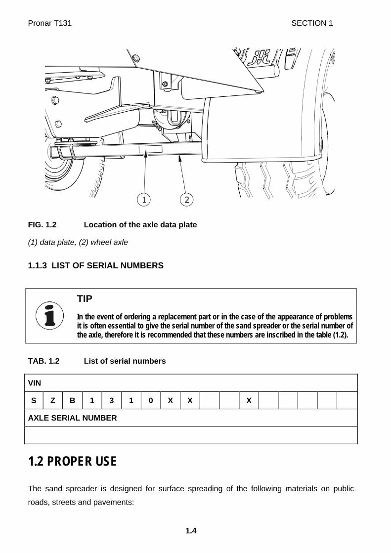
1.1.2 AXLE IDENTIFICATION
The serial number of the axle shaft and its type are stamped onto the data plate (1) secured
to the axle shaft beam (2) – figure (1.2).
Pronar T131 SECTION 1
1.4
FIG. 1.2 Location of the axle data plate
(1) data plate, (2) wheel axle
1.1.3 LIST OF SERIAL NUMBERS
TIP
In the event of ordering a replacement part or in the case of the appearance of problems it is often essential to give the serial number of the sand spreader or the serial number of the axle, therefore it is recommended that these numbers are inscribed in the table (1.2).
TAB. 1.2 List of serial numbers
VIN
S Z B 1 3 1 0 X X X
AXLE SERIAL NUMBER
1.2 PROPER USE
The sand spreader is designed for surface spreading of the following materials on public
roads, streets and pavements:

SECTION 1 Pronar T131
1.5
• non-chemical agents,
sand of grain size from 0.1 to 1 mm,
natural or artificial crushed stone of grain size up to 4 mm,
• solid chemical agents:
sodium chloride (NaCl),
calcium chloride (CaCl2)
magnesium chloride (MgCl2),
• mixture of solid chemical agents and non-chemical agents.
Chemical agents are applied in order to eliminate black ice and icing as well as to prevent
icing and slippery conditions after snowfall. Chemical agents are applied only after
mechanical snow clearing (based on the Ordinance of the Minister of the Environment,
Journal of Laws No. 230 item 1960).
The sand spreader must not be used in any way other than that described above. Using it as
intended also involves all actions connected with the safe and proper operation and
maintenance of the machine. Due to the above, the user is obliged to:
• carefully read the OPERATOR'S MANUAL and follow its recommendations,
• understand the machine's operating principle and how to operate it safely and
correctly,
• comply with general safety regulations while working,
• prevent accidents,
• comply with road traffic regulations.
The sand spreader is not intended or designed for transporting people or animals.
The brake system and the light and indicator system meet the requirements of road traffic
regulations. The maximum speed of the sand spreader on public roads is 30 km/h in Poland
(pursuant to Traffic Law Act of June 20th 1997, article 20). In the countries where the sand
spreader is used, the limits stipulated by the road traffic legislation in force in a given country
must be observed. The sand spreader speed must not, however, be greater than the
maximum design speed of 40 km/h.

Pronar T131 SECTION 1
1.6
IMPORTANT!
The sand spreader must not be used for purposes other than those for which it is intended, in particular:
• for transporting people and animals
• for transporting whatever materials
• spreading other materials than those specified in the Operator's Manual.
TAB. 1.3 Agricultural tractor's requirements
CONTENTS UNIT REQUIREMENTS
Pneumatic brake system Pneumatic system 2 - line Nominal pressure of the system Pneumatic system 1 - line Nominal pressure of the system Hydraulic brake system Hydraulic system Nominal pressure of the system
-
bar -
bar -
bar
sockets compliant with PN-
ISO 1728:2007 8
sockets compliant with PN-ISO 1728:2007
5.8
sockets compliant with ISO 7421-1 150
Hydraulic system Hydraulic oil Pressure rating of the system Oil demand: Minimum hydraulic pump capacity
-
MPa l
l/min
L HL 32 Lotos
16 6
32
Electrical system Electrical system voltage Connection socket
V -
12
7 polar compliant with ISO 1724
Tractor hitches Minimum lift capacity (vertical load) of the hitching system
kg
1,000
Other requirements Minimum tractor power demand
kW /
Horsepower
44 (60)

SECTION 1 Pronar T131
1.7
IMPORTANT!
Use of other oil is permitted on condition that it may be mixed with the oil used in the sand spreader. Detailed information may be found on the product information card.
TIP
Information concerning gear oil is provided in chapter 5
1.3 EQUIPMENT
TAB. 1.4 Sand spreader equipment
EQUIPMENT
STA
ND
AR
D
AD
DIT
ION
AL
OPT
ION
OPERATOR'S MANUAL •
WARRANTY BOOK •
Fixed drawbar eye ∅40 •
Rotating drawbar eye ∅50 •
Single conduit pneumatic brake system •
Double conduit pneumatic brake system •
Hydraulic brake system •
Slow-moving vehicle warning sign •
Wheel chocks •
Warning reflective triangle •
Service platform. •
Connection lead for the electrical system •

Pronar T131 SECTION 1
1.8
Information concerning tires is provided at the end of this publication in ANNEX A.
1.4 TERMS & CONDITIONS OF WARRANTY
PRONAR Sp. z o.o., Narew guarantees the reliable operation of the machine when it is used
according to its intended purpose as described in the OPERATOR'S MANUAL. The repair
period is specified in the WARRANTY BOOK.
The warranty does not apply to those parts and sub-assemblies of the machine, which are
subject to wear in normal usage conditions, regardless of the warranty period. Consumables
include the following parts/sub-assemblies:
• drawbar hitching eye,
• pneumatic system connector filters,
• tyres,
• brake shoes,
• conveyor belt,
• tensioners springs,
• seals,
• bearings.
The warranty service only applies to factory defects and mechanical damage that is not due
to the user's fault.
In the event of damage arising from:
• mechanical damage which is the user's fault, caused by road accidents,
• by inappropriate use, adjustment or maintenance, use of the sand spreader for
purposes other than those for which it is intended,
• use of damaged machine,
• repairs carried out by unauthorised persons, improperly carried out repairs,
• making unauthorised alterations to machine design,
the user will lose the right to warranty service.
SECTION 1 Pronar T131
1.9
TIP
Demand that the seller carefully and precisely fills out the WARRANTY BOOK and warranty repair coupons. A missing date of purchase or sale point stamp, may make the user ineligible for any warranty repair or refund.
The user is obliged to report immediately on noticing any wear in the paint coating or traces
of corrosion, and to have the faults rectified whether they are covered by the warranty or not.
For detailed Terms & Conditions of Warranty, please refer to the WARRANTY BOOK
attached to each machine.
Modification of the machine without the written consent of the Manufacturer is forbidden. In
particular, do NOT weld, drill holes in, cut or heat the main structural elements of the
machine, which have a direct impact on the machine operation safety.
1.5 TRANSPORT
The sand spreader is ready for sale completely assembled and does not require packing.
Packing is only required for the machine's technical documentation and any extra fittings. The
slurry tanker is delivered to the user either transported on a vehicle or, after being attached to
a tractor, independently (sand spreader towed with a tractor).
1.5.1 TRANSPORT ON VEHICLE
Loading and unloading of sand spreader from vehicle shall be conducted using loading ramp
with the aid of agricultural tractor, overhead crane or hoisting crane. During work adhere to
the general principles of Health and Safety at Work applicable to reloading work. Persons
operating reloading equipment must have the qualifications required to operate these
machines.
Lifting equipment used for transporting the sand spreader must be attached only to the fixed
structural elements of the machine. These elements are, first of all: frame, drawbar and axle.
IMPORTANT!
Do not secure or attach the sand spreader by drawbar eye, load box and other structural elements that are not sufficiently strong to withstand operations of this type.
Pronar T131 SECTION 1
1.10
The sand spreader should be attached firmly to the platform of the transport vehicle using
straps, chains, stays or other securing measures fitted with a tightening mechanism. In order
to attach the machine in a proper manner, fasten axles, frame longitudinal members and
possibly drawbar. Additionally, support the drawbar with a wooden block of such a height that
the sand spreader frame is positioned parallel to the load platform. Chocks, wooden blocks or
other objects without sharp edges should be placed under the wheels of the sand spreader to
prevent it from rolling. Wheel blocks must be nailed to the load platform planks of the vehicle
or secured in another manner preventing their movement.
Use certified and technically reliable securing measures. Worn straps, cracked securing
catches, bent or corroded hooks as well as other damage may disqualify use of the given
element from use. Carefully read the information stated in the Operator's Manual for the
given securing measure. The number of securing elements (cables, straps, chains and stays
etc.) and the force necessary for their tensioning depends on a number of things, including
weight of the machine, the construction of vehicle carrying it, speed of travel and other
conditions. For this reason it is impossible to define the securing plan precisely.
A correctly secured machine does not change its position with regard to the transport in
vehicle. The securing elements must be selected according to the guidelines of the
Manufacturer of these elements. In case of doubt apply a greater number of securing straps
in order to immobilise the machine. If necessary, sharp edges of sand spreader should be
protected at the same time protecting the securing straps from breaking during transport.
DANGER
Incorrect application of securing measures may cause an accident.
During reloading work, particular care should be taken not to damage parts of the machine's
fittings or the lacquer coating. The tare weight of the sand spreader is given in table (3.1).

SECTION 1 Pronar T131
1.11
IMPORTANT!
When being road transported on a motor vehicle the sand spreader must be mounted on the vehicle's platform in accordance with the transport safety requirements and the regulations. Driver of the vehicle should be particularly careful during travel. This is due to the vehicle's centre of gravity shifting upwards when loaded with the machine. Use only certified and technically reliable securing measures. Carefully read the manufacturer's instructions for the securing measures.
1.5.2 INDEPENDENT TRANSPORT BY THE USER
In the event of independent transport by the user, carefully read the OPERATORS MANUAL
and follow its recommendations. Independent transport involves towing the machine with own
agricultural tractor to destination. During transport adjust travel speed to the prevailing road
conditions, but do not exceed the maximum design speed.
IMPORTANT!
Before transporting independently, the tractor driver must carefully read this operator's manual and observe its recommendations.
1.6 ENVIRONMENTAL HAZARDS
A hydraulic or gear oil leak constitutes a direct threat to the natural environment owing to its
limited biodegradability. The negligible solubility of hydraulic oil in water does not cause
extreme toxicity of organisms living in the aquatic environment. The formation of a film of oil
on the water may be the direct cause of physical action on organism, perhaps causing
change of oxygen values in the water because of lack of direct contact of air with the water.
An oil leak into water reservoirs may however lead to a reduction of the oxygen content.
While carrying out maintenance and repair work, which involves the risk of an oil leak, this
work should take place on an oil resistant floor or surface. In the event of oil leaking into the
environment, first of all contain the source of the leak, and then collect the leaked oil using
available means. Remaining oil should be collected using sorbents, or by mixing the oil with
sand, sawdust or other absorbent materials. The oil pollution, once gathered up, should be
kept in a sealed, marked, hydrocarbon resistant container. The container should be kept
away from heat sources, flammable materials and food.

Pronar T131 SECTION 1
1.12
DANGER
Used hydraulic or gear oil or gathered remains mixed with absorbent material should be stored in a precisely marked container. Do not use food packaging for this purpose.
Oil, which has been used up or is unsuitable for further use owing to a loss of its properties
should be stored in its original packaging in the conditions described above. Waste oil should
be taken to the appropriate facility dealing with the re-use of this type of waste. Waste code
(L-HL 32 Lotos hydraulic oil): 13 01 10. Detailed information concerning hydraulic oil may be
found on the product's Material Safety Data Sheet.
TIP
The hydraulic system of the sand spreader is filled with L-HL32 Lotos hydraulic oil. Please refer to Chapter 5 for information on transmission oil used.
IMPORTANT!
Waste oil should only be taken to the appropriate facility dealing with the re-use of this type of waste. Do NOT throw or pour oil into sewerage or water tanks.
1.7 WITHDRAWAL FROM USE
In the event of decision by the user to withdraw the sand spreader from use, comply with the
regulations in force in the given country concerning withdrawal from use and recycling of
machines withdrawn from use. Before proceeding to dismantle equipment oil shall be
completely removed from hydraulic system and gearbox.
DANGER
During dismantling use the appropriate tools, equipment (overhead travelling crane, crane or hoist etc.), using personal protection equipment, i.e. protective clothing, footwear, gloves and eye protection etc. Avoid contact of skin with oil. Do not allow used hydraulic oil to spill.

SECTION 1 Pronar T131
1.13
Worn out or damaged parts that cannot be reclaimed should be taken to a collection point for
recyclable raw materials. Hydraulic and gear oil should be taken to the appropriate facility
dealing with the re-use of this type of waste.

Pronar T131 SECTION 1
1.14

SECTION
2
SAFETY ADVICE

Pronar T131 SECTION 2
2.2
2.1 BASIC SAFETY RULES
2.1.1 BASIC SAFETY RULES
• Before using the sand spreader, the user must carefully read this operator's
manual. When operating the machine, the operator must comply with all the
recommendations included in the operator's manual. Do NOT start the sand
spreader without knowledge of its function.
• The user is obliged to acquaint himself with the construction, action and the
principles of safe usage of the machine.
• Before using the sand spreader always check the machine, whether it is properly
prepared for work, especially in terms of safety.
• If the information stated in the Operator's Manual is difficult to understand, contact
a seller, who runs an authorised technical service on behalf of the Manufacturer,
or contact the Manufacturer directly.
• Careless and improper use and operation of the sand spreader and also non-
observance of the recommendations contained in this Operator's Manual,
endanger health and life third persons and/or machine operator.
• Be aware of the existence of a residual risk, and for this reason the fundamental
basis for using this sand spreader should be the application of safety rules and
sensible behaviour.
• The machine must never be used by persons who are not authorised to drive the
agricultural tractors and not trained in the safety principles and use of the
machine, including children and people under the influence of alcohol.
• The sand spreader must not be used for purposes other than those for which it is
intended. Anyone who uses the machine other than the way intended takes full
responsibility for himself for any consequences of this use. Use of the machine for
purposes other than those for which it is intended by the Manufacturer may
invalidate the warranty. Use other than intended means also spreading agents
other than those recommended by the machine Manufacturer.
• Any modification to the sand spreader frees the manufacturer from any
responsibility for damage or detriment to health which may arise as a result.

SECTION 2 Pronar T131
2.3
• Before using the sand spreader always check its technical condition. In particular,
check the technical condition of the hitch system, axle system, brake system,
indicator lights, spreader unit, feeding mechanism and set of safety guards.
• The user is obliged to acquaint himself with the principles of safe operation,
adjustment methods and inspection points of the sand spreader and with the risks
resulting from operation and maintenance of the machine.
• People, animal or objects must not be carried on the machine.
• The sand spreader may be operated only by one person at a time.
• The sand spreader may only be used when all the safety guards and other
protective elements are technically sound and correctly positioned. In the event of
loss or destruction of the safety guards, they must be replaced with new ones.
2.1.2 HITCHING AND UNHITCHING FROM TRACTOR
• Be especially careful when hitching and unhitching the machine.
• Only hitch spreader to an agricultural tractor equipped with side mirrors, which
provide visibility on both sides of the machine.
• While hitching the sand spreader to the tractor, use the appropriate hitch. After
completing the hitching of the machines check the safety of the hitch Carefully
read the tractor Operator's Manual. If the tractor is equipped with an automatic
hitch, make certain that the coupling operation is completed.
• When hitching, there must be nobody between the sand spreader and the tractor.
• Do NOT hitch the machines to tractor, if the tractor does not meet the
requirements of the Manufacturer (minimum tractor power demand, wrong
connection etc.) – compare table (1.3) AGRICULTURAL TRACTOR
REQUIREMENTS. Before hitching the machine, make certain that oil in the
external hydraulic system of tractor may be mixed with the hydraulic oil in the
machine's hydraulic system.
• When connecting the hydraulic lines to the tractor, make sure that the tractor and
sand spreader hydraulic system are not under pressure. If necessary reduce
residual pressure in the system.

Pronar T131 SECTION 2
2.4
• Before hitching sand spreader to tractor check that both machines are in good
technical condition. In particular, check the hitching system and hydraulic,
electrical, pneumatic connectors and sockets on the tractor and sand spreader.
• The machine disconnected from the tractor must be on level ground and be
supported by the parking stand and secured against rolling using parking brake
and wheel chocks. Lines terminals should be protected against contamination.
2.1.3 HYDRAULIC AND PNEUMATIC SYSTEM
• The sand spreader hydraulic system is under high pressure when operating.
• Regularly check the condition of the connections and the hydraulic and pneumatic
leads. There must not be any leaks of hydraulic oil.
• In the event of malfunction of the hydraulic or pneumatic system, do not use the
sand spreader until the malfunction is corrected.
• Coupling and towing of a defective spreader (eg in order to deliver the machine to
a service) is allowed only when the chassis, axle system, drawbar and brakes
are fully operational.
• Before proceeding to maintenance-repair work, make certain that the hydraulic
system is not under pressure.
• Rubber hydraulic conduits must be replaced every 4 years regardless of their
technical condition.
• Use the hydraulic oil recommended by the Manufacturer.
• After changing the hydraulic oil, the used oil should be properly disposed of. Used
oil or oil, which has lost its properties, should be stored in original containers or
replacement containers resistant to action of hydrocarbons. Replacement
containers must be clearly marked and appropriately stored.
• Do not store hydraulic oil in packaging designed for storing food or foodstuffs.
2.1.4 CLEANING, MAINTENANCE AND ADJUSTMENT
• Maintenance and repair works may be performed after hitching the sand spreader
to the tractor. In such a case, switch off the tractor engine, remove the key from
the ignition and immobilise the tractor and sand spreader with parking brake.
Ensure that unauthorised persons do not have access to the tractor cab. Protect

SECTION 2 Pronar T131
2.5
the machine against rolling by placing blocking chocks under the wheels. When
performing works that do not require hitching to tractor, position the sand
spreader on level and hard surface, support it using a parking stand and protect it
against rolling by placing chocks under the wheels. Place of work should be dry,
clean and well-lighted.
• Regularly check the condition of the bolt and nut connections.
• During the warranty period, any repairs may only be carried out by Warranty
Service authorised by the manufacturer. After the expiry of the warranty period it
is recommended that possible repairs to the machine be performed by specialised
workshops.
• During work use the proper, close-fitting protective clothing, gloves, protective
goggles and appropriate tools.
• Reduce the oil or air pressure in the sand spreader before dismantling the
hydraulic or pneumatic elements.
• In the event of any fault or damage whatsoever, do not use the machine until the
fault has been corrected.
• Servicing and repair work should be carried out in line with the general principles
of workplace health and safety. In the event of injury, the wound must be
immediately cleaned and disinfected. In the event of more serious injuries, seek a
doctor's advice.
• Service inspections of the sand spreader should be carried out according to the
frequency specified in this Operator's Manual.
• Welding works may be performed only by persons having appropriate
authorisations for this type of works.
• Before welding or electrical work, the sand spreader should be disconnected from
the power supply, if the machine is connected to the tractor (disconnect the
tractor negative battery cable (-) or disconnect connection lead). The paint coating
should be cleaned. Burning paint fumes are poisonous for people and animals.
Welding work should be carried out in a well lit and well ventilated space.
• Be especially careful when welding and pay attention to flammable or fusible
elements (hydraulic system conduits, electrical system leads and other structural
elements made of plastics). If there is a risk that they will catch fire or be

Pronar T131 SECTION 2
2.6
damaged, they should be removed or covered with non-flammable material
before commencing welding work. Before beginning work prepare a CO2 or foam
extinguisher.
• In the event of work requiring the sand spreader to be raised, use properly
certified hydraulic or mechanical lifts for this purpose. After lifting the machine,
stable and durable supports must also be used. Do NOT carry out work under a
machine, which has only been raised with the lift jack.
• The machine must not be supported using fragile elements (bricks or concrete
blocks).
• After completing work associated with lubrication, remove excess oil or grease.
The machine should be kept clean and tidy.
• Do NOT perform independent repair of hydraulic or pneumatic cylinders, valves,
etc. In the event of damage to these elements, repair should be entrusted to
authorised service point or replace elements with new parts.
• Do NOT make repairs to drawbar and drawbar eye (straightening, repairing or
welding). A damaged drawbar or drawbar eye must be replaced.
• Do NOT install additional appliances or fittings not according to the specifications
defined by the Manufacturer.
• Should it be necessary to change individual parts, use only original parts or those
indicated by the Manufacturer. Non-adherence to these requirements may put the
user and other people's health and life at risk, and also damage the machine.
• In the event of injuries being caused by pressurised hydraulic oil, contact a doctor
immediately. Hydraulic oil may find its way under the skin and cause infections. In
the event of contact of oil with eye, rinse with large quantity of water and in the
event of the occurrence of irritation consult a doctor. In the event of contact of oil
with skin wash the area of contact with water and soap. Do NOT apply organic
solvents (petrol, kerosene).
• After completion of works, make sure that no tools are left inside the load box, on
the belt conveyor or on the adapter discs.
• The sand spreader can only be stood on when it is absolutely motionless and the
tractor engine is switched off. Agricultural tractor and sand spreader must be
immobilised with parking brake. Before entering the sand spreader, ensure that

SECTION 2 Pronar T131
2.7
unauthorised persons do not have access to the tractor and remove key from
ignition.
• Remove the remains of load from the sand spreader each time after finished
work. Check spreader unit rear guard is contaminated and clean if necessary.
2.1.5 LOADING THE SAND SPREADER AND SPREADING
• Do NOT exceed the sand spreader's maximum carrying capacity. Exceeding the
carrying capacity may lead to damage to the machine, loss of stability while
driving, scattering of the load and danger while working or driving.
• Before loading make certain that there are no stones, tools or other objects in the
load box and on the adapter's discs.
• While reversing, the sand spreader drive must be disengaged.
• Do NOT leave the tractor cab, when the spreader unit drive and the feeding
mechanism drive are engaged.
• When spreading is completed, disengage the hydraulic drive of the feeding
mechanism and discs.
• The load in the sand spreader's load box must be distributed uniformly.
• The sand spreader drive may be started only when there are no bystanders or
animals within the radius of approximately 3 metres from the machine.
• Spreading agents must be prepared in accordance with the regulations
concerning winter road maintenance in force in the country in which the sand
spreader is used. Spreading agents other than those recommended by the
Manufacturer must not be used.
• Unused load should be unloaded in the storage area to prevent the load from
freezing in the sand spreader's load box.
• Use parking stand in the event you need to lift the spreader screen.
2.1.6 DRIVING ON PUBLIC ROADS
• When driving on public roads, comply with the road traffic regulations.
• Exceeding the maximum load capacity of the sand spreader may damage it, and
also threaten the safety of traffic.

Pronar T131 SECTION 2
2.8
• Place the slow-moving vehicle warning sign on the back wall.
FIG. 2.1 Mounting place for slow-moving vehicle sign
(1) warning sign, (2) attachment point
• While driving on public roads the sand spreader must be fitted with a certified or
authorised reflective warning triangle.
• During sand spreader operation, the tractor must be equipped with the yellow
beacon light.
• The sand spreader must NOT be left unsecured. Engage parking brake and place
chocks under wheels to protect the machine from rolling.
• Do not exceed the maximum speed limit. Adjust driving speed to the road
conditions.

SECTION 2 Pronar T131
2.9
FIG. 2.2 Method of placing chocks
(1) chocks
2.1.7 TYRES
• When working with tyres, the sand spreader should be secured against rolling by
placing chocks under the wheels. Wheels can be taken off the machine axle only
when the machine is not loaded.
• Repair work on the wheels or tyres should be carried out by persons trained and
entitled to do so. This work should be carried out using appropriate tools.
• Inspection of nut tightening should be carried out after first use of sand spreader,
after first day of work under load and then every month of use. The inspection
should be repeated individually if a wheel has been removed from the wheel axle.
• Avoid potholes, sudden manoeuvres or high speeds when turning.
• Check the tyre pressure regularly. Owing to the large temperature differences in
winter, it is recommended that the air pressure be checked more often.
• Protect tyre valves using suitable caps to avoid soiling.

Pronar T131 SECTION 2
2.10
2.1.8 DESCRIPTION OF RESIDUAL RISK
Pronar Sp. z o. o. in Narew has made every effort to eliminate the risk of accidents. There is,
however, a certain residual risk, which could lead to an accident, and this is connected
mainly with the actions described below:
• using the sweeper for purposes other than those for which it is intended,
• being between the tractor and the machine while the engine is running and when
the machine is being hitched,
• being on the machine while the engine is running,
• operating the machine with removed or faulty safety guards,
• not maintaining a safe distance from the machine during its operation and
loading,
• operation of the machine by persons under the influence of alcohol
• cleaning, maintenance and technical checks of the machine,
• work of machine on unstable and sloping surface.
The residual risk may be kept to a minimum by following the recommendations below:
• prudent and unhurried operation of the machine,
• adherence to the remarks and recommendations stated in the OPERATOR'S
MANUAL,
• maintaining safe distance from forbidden or dangerous zones,
• a ban on being on the machine when it is operating,
• carrying out repair and maintenance work in line with operating safety rules and
carrying out such work by trained persons,
• using close fitting protective clothing,
• ensuring unauthorised persons have no access to the machine, especially
children.
2.2 INFORMATION AND WARNING DECALS
The machine is labelled with the information and warning decals mentioned in table (2.1).
The symbols are positioned as presented in figures (2.3) and (2.4). Throughout the time it is
SECTION 2 Pronar T131
2.11
in use, the user of the machine is obliged to take care that notices and warning and
information symbols located on the sand spreader are clear and legible. In the event of their
destruction, they must be replaced with new ones. Safety decals are available from your
PRONAR dealer or directly from PRONAR customer service. New assemblies, changed
during repair, must be labelled once again with the appropriate safety signs. During sand
spreader cleaning do not use solvents which may damage the coating of information label
stickers and do not subject them to strong water jets.
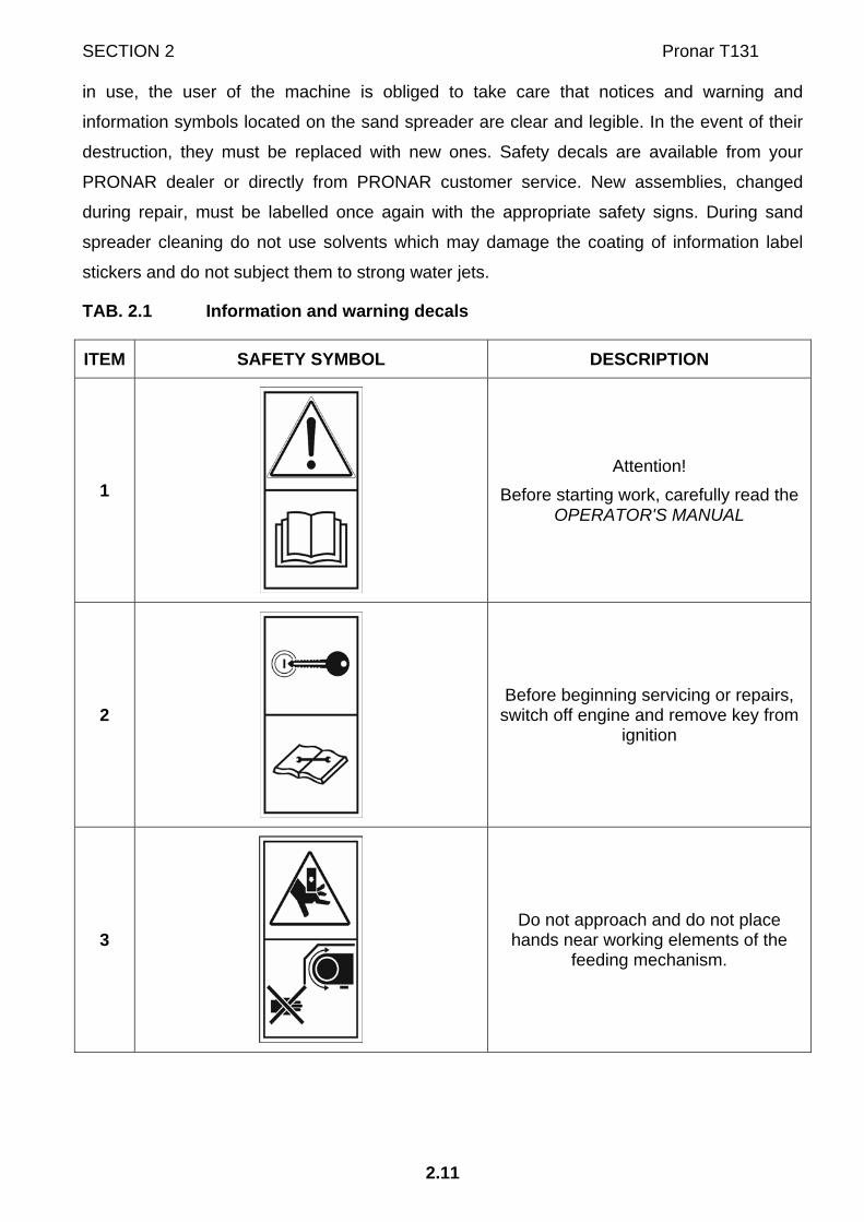
TAB. 2.1 Information and warning decals
ITEM SAFETY SYMBOL DESCRIPTION
1
Attention! Before starting work, carefully read the
OPERATOR'S MANUAL
2
Before beginning servicing or repairs, switch off engine and remove key from
ignition
3
Do not approach and do not place hands near working elements of the
feeding mechanism.

Pronar T131 SECTION 2
2.12
ITEM SAFETY SYMBOL DESCRIPTION
4
Do not approach and do not touch rotating discs of the spreader unit.
5
Attention! Do not stand on the operating feeding
mechanism.
6
Risk of impact by debris. Keep a safe distance from the spreader
unit while it is operating.
7
Check the condition of the screw and nut connections of the wheel axles
regularly
8
Grease according to the recommendations in the OPERATOR'S
MANUAL.

SECTION 2 Pronar T131
2.13
ITEM SAFETY SYMBOL DESCRIPTION
9
Air pressure in the tyres.
10
Machine type.

Pronar T131 SECTION 2
2.14
FIG. 2.3 Locations of information and warning decals.

SECTION 2 Pronar T131
2.15
FIG. 2.4 Locations of information and warning decals.

Pronar T131 SECTION 2
2.16

SECTION
3
DESIGN AND OPERATION
AND OPERATION

Pronar T131 SECTION 3
3.2
3.1 TECHNICAL SPECIFICATION
TAB. 3.1 Basic technical specification
CONTENTS UNIT DATA
Dimensions Total length Total width Total height
mm mm mm
5,500 1,840 1,950
Technical specification Cargo capacity Maximum design carrying capacity Sand spreader tare weight Minimum tractor power demand
m3
kg kg
hp (kW)
3
3,800 1,360
60 (44)
Hydraulic system System capacity Nominal pressure of the system Minimum tractor pump capacity Hydraulic oil
l
MPa l/min
-
6
16 32
L HL32 Lotos
Feeding mechanism and spreader unit Width of the feeding mechanism conveyor Quantity of adapter discs Maximum rotation speed of adapter discs (1)
Mm
- RPM
800 2
150
Other information Electrical system voltage Axle track Maximum design speed Maximum vertical drawbar load Recommended sand spreader working speed Level of acoustic power Spreading width
V
mm km/h
kg km/h dB mm
12
1,500 40
1,000 4 - 10
below 70 1,700 – 3,000
(1) – with the tractor hydraulic pump capacity at 32 l/min

SECTION 2 Pronar T131
3.3
3.2 CHASSIS
Sand spreader chassis consists of subassemblies indicated on figure (3.1). Lower frame (1)
of the sand spreader is a structure welded from steel sections. The main support elements of
the frame are two longitudinal members connected with crossbars.
In the rear section of the frame there are elements for securing the wheel axle. Wheel axle
(2) consists of square bar terminated with a pin, on which wheel hubs are mounted on cone
bearings. The wheels are single, equipped with brake shoes activated through mechanical
expander cams.
FIG. 3.1 Sand spreader chassis
(1) lower frame, (2) wheel axle, (3) wheel, (4) drawbar, (5) support, (6) parking brake
mechanism, (7) mudguard, (8) drawbar hitching eye
Sand spreader is equipped with drawbar (4) secured to the faceplate of the frame.
Depending on requirements, drawbar position can be changed by the sand spreader
operator. In the front section of the frame there is support with wheel (5) bolted to the left
longitudinal member. The bolt mechanism of the parking brake (6) is welded underneath, on
the left side of the frame. Elements of electrical lighting system, hydraulic system, pneumatic

Pronar T131 SECTION 3
3.4
system and load box are mounted to the frame structure. In the rear section of the frame
shields and spreader unit are mounted.
3.3 LOAD BOX
Sand spreader load box (1) has a monocoque construction. The load box interior is equipped
with bows (6) fixed to the load box walls. Pipes (3), which reduce load on the feeding
mechanism during sand spreader operation, are bolted to the bows.
FIG. 3.2 Load box
(1) load box, (2) screen, (3) pipe, (4) screen support, (5) lights support beam, (6) bow, (7)
service platform
On the upper part of the load box there are two screens (2) which can be raised and propped
with support (4), if needed. Beam (5) with license plate light is bolted to the rear wall of the
load box. The load box is mounted on feeding mechanism frame. In the lower section of the

SECTION 2 Pronar T131
3.5
load box there are rubber shields fixed to the side walls edges, front wall and rear wall. These
shields prevent loss of load during travel and operation of sand spreader.
3.4 FEEDING MECHANISM
FIG. 3.3 Feeding mechanism
(1) feeding table, (2) front roller, (3) rear drive roller, (4) conveyor belt, (5) guide roller, (6)
reduction gear, (7) hydraulic motor, (8) light bracket, (9) bearing assembly
Design of feeding mechanism is shown on figure (3.3). Feeding table (1) is a support
structure for individual elements of feeding mechanism. Between longitudinal members there
are 20 guide rollers (5) installed on which conveyor belt (4) moves. In the front section of the
mechanism there is front roller (2) connected with belt tensioner.

Pronar T131 SECTION 3
3.6
In the rear section of the mechanism there is rear drive roller (3) to which reduction gear (6)
is fixed (on the right side). Thanks to the design of rollers (2) and (3), the conveyor belt can
work without slipping. The roller is driven by hydraulic motor (7). Rear light brackets (8) are
bolted to the longitudinal members of the feeding table, on the left and right side of the
feeding mechanism.
3.5 SPREADER UNIT
FIG. 3.4 Spreader unit
(1) right spreading disc, (2) left spreading disc, (3) spreader unit base, (4) hydraulic motor
Spreader unit base (3) is secured to the sand spreader frame brackets located in the rear
section of the machine – figure (3.4). Hydraulic motors (4) are bolted to the frame. Right
spreading disc (1) and left spreading disc (2) are mounted on the hydraulic motors.
Position of both spreading discs can be adjusted. Spreading disc blades can be adjusted
depending on requirements. Spreading agent is transported on conveyor belt and fed to
spreader unit discs.

SECTION 2 Pronar T131
3.7
FIG. 3.5 Spreader unit discs
(1) left spreading disc, (2) right spreading disc, (3) spreading blades, (A) front of sand
spreader, (B) rotation direction of spreader unit discs
Spreader unit is placed under protection guards (1) made of sheet steel, figure (3.6). Shields
are connected together with bolts and fixed to shield frame. Complete unit is installed in
appropriate seats on the sand spreader frame by means of brackets.

Pronar T131 SECTION 3
3.8
FIG. 3.6 Spreader unit shields
(1) set of rear guards, (2) ladder
3.6 HYDRAULIC SYSTEM
Hydraulic system of the sand spreader drives the spreader unit and feeding mechanism. This
hydraulic system is supplied from the external hydraulic system of the tractor. Hydraulic oil
flows through supply connection (1) and gets to flow regulator (4) - to connection (P).
Hydraulic oil flows out of outlet (A) and supplies hydraulic motor (3) which drives reduction
gear (9) and next, conveyor belt.

SECTION 2 Pronar T131
3.9
FIG. 3.7 Hydraulic system
(1) supply connection, (2) return connection, (3) hydraulic motor, (4) flow regulator, (5) check
valve, (6) flow divider, (7) hydraulic motor of right spreading disc, (8) hydraulic motor of left
spreading disc, (9) reduction gear
Hydraulic motors (7) and (8) are supplied with oil returning from hydraulic motor (3) and oil
stream from flow regulator, from connection (T), flowing first through flow divider (6). Finally,
hydraulic oil returns to the tractor hydraulic system through check valve (5) located in front of
return connection (2).
Flow regulator is equipped with a knob adjusting oil output on the receiver's connection. Flow
regulator setting determines conveyor belt speed and consequently, density of spreading
material. Flow regulator is located in the front section of the sand spreader, under shield,
behind the machine drawbar. Flow regulator setting determines only conveyor belt speed. If
flow regulator setting is changed, rotation speed of spreader unit discs is only insignificantly
changed. If flow regulator setting is 1, conveyor belt should stop. If the setting is increased
above 4, conveyor belt speed will not be further increased. Check valve (5) precludes

Pronar T131 SECTION 3
3.10
movement of the feeding mechanism conveyor in the opposite direction (i.e. towards the front
wall of the load box).
FIG. 3.8 Flow regulator
(1) flow regulator, (2) shield, (3) adjusting knob with scale, (P) supply, (A) receiver, (T) return
3.7 PNEUMATIC BRAKE SYSTEM
Depending on the version, the sand spreader is equipped with one of the two types of
working brake system:
• single line pneumatic system with three position regulator, figure (3.9),
• double line pneumatic system with three position regulator, figure (3.10).
Working brake is activated from the tractor driver's seat by pressing on the brake pedal in the
tractor. The control valve activates the sand spreader brakes when the brake pedal is

SECTION 2 Pronar T131
3.11
pressed in the tractor. Furthermore, in case of an inadvertent disconnection of the line
between the sand spreader and the tractor, the control valve will automatically activate sand
spreader's brakes.
FIG. 3.9 Single line pneumatic system
(1) air tank, (2) control valve, (3) brake force regulator, (4) air filter, (5) line connection, (6)
diaphragm pneumatic cylinder, (7) cylinder control connection, (8) air tank control connection,
(9) drain valve

Pronar T131 SECTION 3
3.12
FIG. 3.10 Double line pneumatic system
(1) air tank, (2) control valve, (3) brake force regulator, (4) air filter, (5) red line connection (6)
yellow line connection, (7) diaphragm pneumatic cylinder, (8) cylinder control connection,
(9) air tank control connectors, (10) drain valve
Valve used in the system is equipped with a circuit causing the brakes to be applied when
sand spreader is disconnected from the tractor. When compressed air line is connected to
the tractor, the device automatically applying the brakes now changes its position to allow
normal brake operation.
Three-step brake force regulator in pneumatic system adjusts braking force depending on the
regulator's setting. Switching to a suitable working mode is done manually by sand spreader
operator using the regulator lever prior to moving off. The regulator has 3 working positions:
"no load", "half load", "full load".

SECTION 2 Pronar T131
3.13
FIG. 3.11 Three-step brake force regulator
(1) braking force regulator, (2) lever, (A) "no load" (B) "half load", (C) "full load"
3.8 PARKING BRAKE
The parking brake is for immobilising sand spreader while standing motionless. The brake
crank mechanism (1) – located on the left side of chassis frame - is connected with axle
rudder bar using a steel cable (3). Rotation of the crank increases tension of the steel cable.
Expander arms exert pressure or brake shoes and cause the axle to brake. Prior to moving
off, handbrake must be released - steel cable must hang loose.

Pronar T131 SECTION 3
3.14
FIG. 3.12 Parking brake of sand spreader
(1) brake crank mechanism, (2) handbrake release, (3) steel cable, (4) guide roller
3.9 ELECTRICAL SYSTEM, WARNING SIGNS AND INDICATORS
The sand spreader electrical system is designed for supply from direct current source of 12
V. Connection of the sand spreader electrical system with the tractor should be made through
an appropriate connection lead delivered with the machine. The sand spreader is also
equipped with orange lateral reflectors. The machine is connected to electrical system of the
tractor with electrical line included in standard equipment of the sand spreader.

SECTION 2 Pronar T131
3.15
FIG. 3.13 Positioning of electrical components and reflective lights, front view
(1) front left parking light, (2) 7-pole connection socket, (3) orange lateral reflector

Pronar T131 SECTION 3
3.16
FIG. 3.14 Positioning of electrical components and reflective lights, rear view
(1) left rear lamp assembly, (2) right rear lamp assembly, (3) license plate light, (4) orange
lateral reflector

SECTION 2 Pronar T131
3.17
FIG. 3.15 Electrical system diagram
(GP) seven-pin socket (PP), (PL) left/right front parking light, (ZP),(ZL) left/right rear lamp
assembly, (OTP)/(OTL) left/right license plate light

Pronar T131 SECTION 3
3.18

SECTION
4
CORRECT USE ADVICE

Pronar T131 SECTION 4
4.2
4.1 PREPARATION OF THE SAND SPREADER FOR WORK
4.1.1 PRELIMINARY INFORMATION
The sand spreader is supplied to the user completely assembled and does not require
additional mounting operations of machine sub-assemblies. The manufacturer guarantees
that the machine is fully operational and has been checked according to quality control
procedures and is ready for use. This does not release the user from an obligation to check
the machine's condition prior to purchasing and before first use.
4.1.2 HAND-OVER AND INSPECTION OF THE MACHINE AFTER DELIVERY
After delivery of the machine to the buyer, the user is obliged to check technical condition of
the sand spreader (one-time inspection). While buying the machine, the user must be
informed by the seller about the method of use of the machine, risks resulting from the use
for purposes other than intended, the method of the machine hitching and the principles of
the machine construction and design. Detailed information concerning the machine hand-
over are included in the WARRANTY BOOK.
Checking the sand spreader after delivery
Check completeness of the sand spreader according to order.
Check technical condition of safety guards.
Check condition of paint coating; check the machine for traces of corrosion.
Check the machine for damage resulting from wrong transport of the machine
to its destination (crushing, piercing, bending or breaking of minor elements
etc.).
Check technical condition of the rubber belt of the feeding mechanism.
Check air pressure in tyres and check correct tightening of wheel nuts.
Check technical condition of drawbar eye and if correctly installed.
Check the condition of bolt and nut connections of the sand spreader unit
shields and fixing of spreader unit discs.
If non-conformities are found, do not attach and start the sand spreader. Discovered defects
should be notified directly to the seller in order to remove them.

SECTION 4 Pronar T131
4.3
ATTENTION!
The seller is obliged to conduct the first start up of the sand spreader in the presence of the user. The user trained by the seller is not released from the obligation to read this operator’s manual carefully.
4.1.3 PREPARING THE SAND SPREADER FOR THE FIRST USE, TEST RUN OF THE SPREADER
TIP
All service activities are described in detail in further parts of the Operator’s Manual.
Preparing for the test run
The user must carefully read this OPERATOR’S MANUAL and observe all
recommendations.
Visually inspect the sand spreader according to guidelines presented in
section PREPARING THE SAND SPREADER FOR NORMAL USE.
Hitch sand spreader to tractor. Immobilise tractor with parking brake.
Release sand spreader’s parking brake.
Test start
Make sure there are object or living animals in the load box.
Start the tractor, check correct operation of lights and indicators by turning on
individual lights.
Start the drive of the feeding mechanism and spreading discs. By changing
the setting of the flow regulator check whether the feeding mechanism tape
speed varies depending on the set value. Turn off the drive.
Release tractor’s parking brake. Perform test drive.
While driving check correct operation of brakes.

Pronar T131 SECTION 4
4.4
After stopping the tractor, turn off the engine, immobilize the spreader and
tractor with parking brake. Check the tightness of the hydraulic system.
If during test run worrying symptoms occur such as:
• excessive noise and abnormal sounds originating from the rubbing of moving
elements,
• hydraulic oil leak,
• improper operation of the hydraulic, electric or pneumatic system,
• other suspected faults,
immediately stop the tractor and turn off the feeding mechanism drive. If a fault cannot be
rectified or the repair could void the warranty, please contact retailer for additional
clarifications or to perform the repair.
4.1.4 PREPARE THE SAND SPREADER FOR NORMAL USE
Scope of inspection activities
Visually inspect if the tyres are properly inflated. In case of doubt, carefully
check tyre pressure.
Check technical condition of drawbar eye.
Check technical condition and completeness of safety guards.
Check if spreader unit blades are properly attached.
Check if rear covers (inner side) are clean.
Check if the load in the load box is not frozen.
ATTENTION!
After completed operation of the sand spreader, the remaining material must be unloaded in the storage area. Before operating the sand spreader, the user is obliged to check the load box, especially if the machine is operated by several operators. Trapped and frozen material may cause serious damage to the belt conveyor’s mechanisms.

SECTION 4 Pronar T131
4.5
DANGER
Careless and improper use and operation of the sand spreader, and non-compliance with the recommendations given in this operator's manual is dangerous to your health. The sand spreader must never be used by persons, who are not authorised to drive agricultural tractors, including children and people under the influence of alcohol or other drugs. Non-compliance with the safety rules of this Operator’s Manual can be dangerous to the health and life of the operator and others.
4.2 HITCHING AND UNHITCHING THE SAND SPREADER
Ensure that pneumatic, hydraulic and electric connections and the hitch of agricultural tractor
are according to the Manufacturer's requirements, if not the sand spreader should not be
hitched to the tractor.
In order to hitch the sand spreader to the tractor perform the steps below in the sequence
presented.
Connection
Position agricultural tractor directly in front of the sand spreader drawbar eye.
Set the drawbar eye with the aid of the support at such a height that it is
possible to hitch the machine.
Reverse tractor, hitch sand spreader, check coupling lock protecting machine
against accidental unhitching.
If the agricultural tractor is equipped with an automatic coupler, ensure
that the hitching operation is completed and that drawbar eye is
secured.
Pronar T131 SECTION 4
4.6
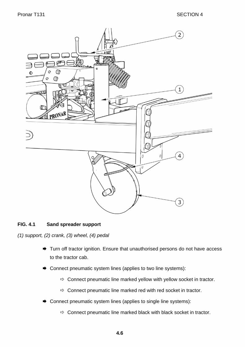
FIG. 4.1 Sand spreader support
(1) support, (2) crank, (3) wheel, (4) pedal
Turn off tractor ignition. Ensure that unauthorised persons do not have access
to the tractor cab.
Connect pneumatic system lines (applies to two line systems):
Connect pneumatic line marked yellow with yellow socket in tractor.
Connect pneumatic line marked red with red socket in tractor.
Connect pneumatic system lines (applies to single line systems):
Connect pneumatic line marked black with black socket in tractor.

SECTION 4 Pronar T131
4.7
Connect hydraulic system lines.
Hydraulic lines are marked with arrows indicating the direction of
hydraulic oil flow.
Connect the wiring to power the electric lighting.
Turning crank (2) – figure (4.1) raise support wheel.
Press support pedal (4) and holding ring in hand (3) place it in transport
position.
Immediately before driving remove wheel chocks and release the sand
spreader parking brake.
DANGER
When hitching, there must be nobody between the sand spreader and the tractor. When hitching the machine, tractor driver must exercise caution and make sure that nobody is present in the hazard zone. When connecting the hydraulic lines to the tractor, make sure that the tractor and sand spreader hydraulic system are not under pressure. Ensure sufficient visibility during hitching. Exercise particular caution during folding support - danger of severing limbs. After completion of hitching check the security of the hitching pin.
During connection of braking system lines (pneumatic double line) the correct sequence of
line connection is very important. First connect the yellow connector to yellow socket in the
tractor and only then connect the red connector to the red socket in the tractor. Once the 2nd
line is connected, the braking system will switch to normal mode of operation (disconnection
or interruption of the lines causes the sand spreader's braking system control valve to
automatically apply brakes). Lines are marked with coloured protective covers, which identify
the appropriate system line.

Pronar T131 SECTION 4
4.8
IMPORTANT!
Ensure compatibility of oils in tractor hydraulic system and in the sand spreader hydraulic system. Sand spreader may only be hitched to a tractor, which has the appropriate hitch, connection sockets for braking, hydraulic and electrical systems, and hydraulic oil in both machines is the same type and may be mixed. When hitching is completed, secure the electrical leads and hydraulic and braking system lines in such a way that they do not become entangled in tractor's moving parts and are not at the risk of breaking or severed when making turns.
Disconnecting the sand spreader
In order to disconnect the sand spreader from the tractor follow these steps.
Immobilise tractor and sand spreader with parking brake.
Turn off tractor ignition. Ensure that unauthorised persons do not have access
to the tractor cab.
Return support wheel to parking position.
Turning crank, set the drawbar eye at such a height that one may safely
unhitch the sand spreader.
Disconnect all hydraulic system lines from tractor.
Disconnect electric lead.
Disconnect pneumatic system conduits (applies to double conduit systems):
Disconnect pneumatic conduit marked red.
Disconnect pneumatic conduit marked yellow.
Disconnect pneumatic system lines (applies to single line systems):
Disconnect pneumatic line marked black.
Protect terminal ends with covers, Place line terminals in appropriate sockets.
Place chocks under manure sand spreader wheel.
Release tractor hitch and disconnect sand spreader drawbar from tractor hitch
and drive tractor away.

SECTION 4 Pronar T131
4.9
DANGER
Exercise caution when disconnecting sand spreader from the tractor. Ensure good visibility. Unless it is necessary, do not go between tractor and sand spreader. Before disconnecting lines and drawbar eye, close tractor cab and secure it against access by unauthorised persons. Turn off tractor's engine.
IMPORTANT!
Do NOT park a loaded sand spreader, which is disconnected from the tractor and resting on the parking stand wheel.
4.3 LOADING
Load box can be loaded only when the sand spreader is connected to the tractor and
positioned horizontally. Always aim at distributing the load uniformly in the load box. This will
ensure stability of the sand spreader when travelling and correct axle and drawbar hitching
eye loads. When loading the load box, it is recommended to use a loader or belt conveyor.
IMPORTANT!
Do NOT exceed the sand spreader's maximum carrying capacity. Do not carry people or animals. Before loading make certain that there are no stones, tools or other objects in the load box and on the adapter's discs. The load in the sand spreader's load box must be distributed uniformly.
Before loading check that there are no objects (tools, stones) in the load box. Avoid throwing
material into the load box from a great height during loading because the feeding mechanism
may be damaged. Loading of materials other than those recommended by the Manufacturer
is forbidden. During loading, the screen should be closed and properly attached to the load
box rim.

Pronar T131 SECTION 4
4.10
IMPORTANT!
Spreading agents must be prepared in accordance with the regulations concerning winter road maintenance in force in the country in which the sand spreader is used. Spreading agents other than those recommended by the Manufacturer must not be used.
4.4 SPREADING AND ADJUSTMENT OF SPREADING MATERIAL DENSITY
FIG. 4.2 Adjustment of conveyor belt speed
(1) flow regulator knob
Amount of spread material depends on the regulator setting and humidity of the material. If
humidity of sand or sand-chemicals mixture is higher, the spread material may slip on the
conveyor surface and a reduced amount of material may be fed to the spreader unit discs.

SECTION 4 Pronar T131
4.11
Speed of the feeding mechanism conveyor depends on the regulator setting. Proper working
position is selected with knob (1). In order to do this, turn the knob completely clockwise to
setting 0; then, turn the knob in the opposite direction (anticlockwise) and select proper
working position (2…4 recommended). The maximum setting is 4. If the setting is increased,
the feeding conveyor speed will not be further increased.
Density of spread material depends on numerous factors: conveyor speed (regulator setting),
blades setting (spread width), travelling speed of the sand spreader, composition of spread
material mixture and its physical properties such as weight, humidity and other. Spreading
density can not be adjusted precisely. This is caused mainly by difficulty in maintaining
constant humidity of spread material as well as various grain size and degree of mixing of
sand-chemicals mixtures.
Figures (4.3), (4.4) oraz (4.5) show the diagrams presenting relation between spread material
density and the sand spreader speed and setting of spreader unit blades.
IMPORTANT!
While reversing, the sand spreader drive must be disengaged. Do NOT leave the tractor cab, when the spreader unit drive and the feeding mechanism drive are engaged. Use of the sand spreader with damaged shields is forbidden.
Measurements of spreading density were made by Pronar personnel during tests of the sand
spreader and they are the basis for determining operating efficiency of the machine. Results
given should be interpreted as approximate ones and settings should be selected on the
basis of experience of sand spreader user, taking into account type of spread material and its
properties. Fine sand of medium humidity, without chemicals, was used during the tests.
Switch on the orange beacon light in the tractor before you start spreading. Conveyor belt
and adapter discs are started from the tractor driver's cab, with the aid of the selective control
valve lever. Check valve in the sand spreader's hydraulic system precludes movement of the
conveyor belt towards the front wall of the load box.
Spreading is recommended to be started during travel of the sand spreader. When the sand
spreader is stopped (e.g. at the traffic lights) or after emptying the load box, the sand
spreader's drive should be disengaged.

Pronar T131 SECTION 4
4.12
FIG. 4.3 Spreading density, diagram 1
(A) front of sand spreader, (B) rotation direction of discs, (I), (II), (III) positions of blades

SECTION 4 Pronar T131
4.13
FIG. 4.4 Spreading density, diagram 2
(A) front of sand spreader, (B) rotation direction of discs, (I), (II), (III) positions of blades

Pronar T131 SECTION 4
4.14
FIG. 4.5 Spreading density, diagram 3
(A) front of sand spreader, (B) rotation direction of discs, (I), (II), (III) positions of blades

SECTION 4 Pronar T131
4.15
DANGER
Use of the sand spreader with damaged shields is forbidden. When driving on public roads, comply with the road traffic regulations. Do not exceed the maximum speed limit. Adjust driving speed to the road conditions. If spreading with the sand spreader is done on pavements special attention should be paid to the bystanders and animals near the machine. During sand spreader operation, the tractor must be equipped with the orange beacon light.
4.5 DRIVING ON PUBLIC ROADS
When driving on public roads, respect the road traffic regulations, exercise caution and
prudence. If the spreading is done on pavements special attention should be paid to the
bystanders likely to be near the working sand spreader. Listed below are the key guidelines
for driving the tractor and trailer combination.
• Before moving off make sure that there are no bystanders, especially children,
near the sand spreader or the tractor. Take care that the driver has sufficient
visibility.
• Make sure that the sand spreader is correctly attached to the tractor and tractor's
hitch is properly secured.
• The sand spreader must not be overloaded, loads must be uniformly distributed
so that the maximum permissible axle and drawbar loads are not exceeded. The
sand spreader's maximum carrying capacity must not be exceeded as this can
damage the machine and pose a risk to the operator or other road users.
• Permissible design speed and maximum speed allowed by road traffic law must
not be exceeded. The towing speed should be adapted to the current road
conditions, load carried by the sand spreader, road surface conditions and other
relevant conditions.
• When not connected to the tractor, the sand spreader must be immobilised using
parking brake and possibly also with chocks or other objects without sharp edges
placed under the front and back wheels. Do NOT leave unsecured sand spreader.
In the event of sand spreader malfunction, pull over on the hard shoulder avoiding

Pronar T131 SECTION 4
4.16
any risk to other road users and position reflective warning triangle according to
traffic regulations.
• While driving on public roads the sand spreader must be fitted with a certified or
authorised reflective warning triangle. When driving, comply with all road traffic
regulations, indicate an intention to turn using indicator lamps, keep all road lights
and indicator lights clean at all times and ensure they are in good condition. Any
damaged or lost lamps or indicator lights must be immediately repaired or
replaced.
• The yellow beacon light should be turned on during sand spreader operation.
• The conveyor belt and the spreader unit drive should be engaged only during
travel of the tractor and sand spreader. When the sand spreader is stopped (e.g.
at the traffic lights), after emptying the load box or while reversing, the sand
spreader's drive should be disengaged.
• Avoid ruts, depressions, ditches or driving on roadside slopes. Driving across
such obstacles could cause the machine or the tractor to suddenly tilt. This is of
special importance because loaded sand spreader's centre of gravity is higher,
which reduces safety. Driving near ditches or canals is dangerous as there is a
risk of the wheels sliding down the slope or the slope collapsing.
• When driving on public roads the sand spreader must be marked with a slow-
moving vehicle warning sign attached to the rear wall of load box.
• When driving, avoid sharp turns especially on slopes.
• Please note that the braking distance of the tractor and slurry tanker combination
is substantially increased at higher speeds and loads.
• Speed must be sufficiently reduced before making a turn or driving on an uneven
road or a slope.
4.6 PROPER USE AND MAINTENANCE OF TYRES
• When working on the tyres, chocks or other objects without sharp edges should
be placed under the wheels of the sand spreader to prevent it from rolling.
Wheels can be taken off the sand spreader axle only when the sand spreader is
not loaded.

SECTION 4 Pronar T131
4.17
• Repair work on the wheels or tyres should be carried out by persons trained and
entitled to do so. This work should be carried out using appropriate tools.
• After removing a wheel, always check how firmly the nuts are screwed in.
Individual checks should be made after the first use, after the first journey with a
load, after travelling 1000 km and then every 6 months. The above actions should
be repeated individually if a wheel has been removed from the wheel axle.
• Regularly check and maintain correct pressure in tyres according to Operator's
Manual (especially if sand spreader is not used for a longer period).
• Pressure and tyres should be also checked after the whole day of intensive work.
Please note that higher temperatures could raise tyre pressure by as much as 1
bar. At high temperatures and pressure, reduce load or speed.
• Do not release air from warm tyres to adjust the pressure or the tyres will be
underinflated when temperatures return to normal.
• Protect tyre valves using suitable caps to avoid soiling.
• Do not exceed the sand spreader's maximum design speed.
• When wrapper is operated all day, stop working for a minimum of one hour in the
afternoon.
• Avoid potholes, sudden manoeuvres or high speeds when turning.

Pronar T131 SECTION 4
4.18

SECTION
5
MAINTENANCE

Pronar T131 SECTION 5
5.2
5.1 PRELIMINARY INFORMATION
When using the sand spreader, regular inspections of its technical condition and the
performance of maintenance procedures are essential, which keep the machine in good
technical condition. In connection with this the user of the sand spreader is obliged to perform
all the maintenance and adjustment procedures defined by the Manufacturer.
Repairs during the warranty period may only be performed by authorised service points.
Detailed procedures and extents of functions are described in this section, which the user
may perform with his own resources. In the event of unauthorised repairs, changes to factory
settings and other actions, which are not regarded as possible for the sand spreader operator
to perform, the user shall invalidate the warranty.
5.2 SERVICING WHEEL AXLE
5.2.1 PRELIMINARY INFORMATION
Work connected with the repair, change or regeneration of axle components should be
entrusted to specialist establishments, having the appropriate technology and qualifications
for this type of work.
The responsibilities of the user are limited to:
• Inspection and adjustment of loose play of axle bearings,
• mounting and dismounting wheel, inspection of wheel tightening,
• checking air pressure, evaluating technical condition of wheels and tyres.
• mechanical brakes adjustment,
• change of parking brake cable and adjustment of cable tension.
Procedures connected with:
• changing grease in axle bearings,
• changing bearings, hub seals,
• repairing wheel axle,
may be performed by specialist workshops.

SECTION 5 Pronar T131
5.3
5.2.2 CHECK WHEEL AXLE BEARINGS FOR LOOSENESS
FIG. 5.1 Lifting jack support point
(1) wheel axle, (2) U bolt
Preparation procedures
Hitch sand spreader to tractor, braking tractor with parking brake.
Park tractor and sand spreader on hard level ground.
Tractor must be placed to drive forward.
Place securing chocks under one sand spreader wheel. Ensure that machine
shall not move during inspection.
Raise the wheel (opposite to the side where chocks are placed).
Lifting jack should be positioned in the place indicated by the arrow in
figure (5.1). Lifting jack must be suited to weight of sand spreader.
Check wheel axle bearings looseness
Turning the wheel slowly in both directions check that movement is smooth
and that the wheel rotates without excessive resistance.
Turn the wheel so that it rotates very quickly, check that the bearing does not
make any unusual sounds.

Pronar T131 SECTION 5
5.4
Holding the wheel above and below, try to feel any looseness.
You may use a lever placed under the wheel supporting the other end
on the floor.
Lower the lifting jack, relocate the chocks to the other wheel and repeat the
inspection procedure for the other wheel.
TIP
Damaged hub cover or lack of hub cover causes penetration of contamination and dampness to hub, which causes significantly faster wear of bearing and hub seals. Bearing life is dependent on sand spreader working conditions, loading, speed of travel and lubrication conditions.
If play is felt, adjust bearing. Unusual sounds coming from bearing may be symptoms of
excess wear, dirt or damage. In such an event the bearing, together with sealing ring, should
be replaced with new parts, or cleaned and greased again
Check wheel axle bearings for looseness • after the first month of use,
• every 6 months of use.
Check condition of hub cover, if necessary replace with new cover. Inspection of bearing
looseness may only be conducted, when the sand spreader is hitched to a tractor. The
machine may not be loaded.
DANGER
Before commencing work the user must read the instructions for lifting and adhere to the manufacturer's instructions. The lifting jack must be stably supported by the ground and so must the axle. Ensure that sand spreader shall not move during inspection of bearing looseness of axles.
5.2.3 ADJUSTMENT OF PLAY OF WHEEL AXLE BEARINGS

SECTION 5 Pronar T131
5.5
Preparation procedures
Prepare tractor and sand spreader for adjustment procedures according to
description provided in section 5.2.2.
Adjustment of road wheel axle bearings
FIG. 5.2 Adjusting half axle bearings
(1) hub cover, (2) castellated nut, (3) securing split cotter pin
Take off hub cover (1) - figure (5.2).
Take out split cotter pin (3) securing castellated nut (2).
Tighten castellated nut in order to eliminate looseness.
Wheel should rotate with insignificant resistance.
Unscrew nut (not less than1/3 rotation) to cover the nearest thread groove
with alignment to opening in wheel stub axle. Wheel should rotate without
excessive resistance.
Nut may not be excessively tightened. Do not apply excessive
pressure with regard for deterioration of bearing working conditions.
Secure castellated nut with cotter pin and mount hub cap.
Delicately tap hub cap with rubber or wooden hammer.

Pronar T131 SECTION 5
5.6
The wheel should turn smoothly without stiffness or detectable resistance. Adjustment of
bearing looseness may only be conducted, when the sand spreader is hitched to a tractor,
and the load box is empty.
TIP
If the wheel is dismounted, bearing looseness is easy to check and adjust.
5.2.4 MOUNTING AND DISMOUNTING WHEEL, INSPECTION OF WHEEL NUT TIGHTENING.
Dismounting wheel
Place chocks under wheel that will not be dismounted.
Ensure that sand spreader shall not move during wheel dismounting.
Loosen wheel nuts according to sequence given in figure (5.3).
Place lifting jack and lift sand spreader.
Dismount wheel.
Wheel mounting
Clean axle pins and nuts of dirt contamination.
Do not grease thread of nuts and pins.
Check condition of pins and nuts, if necessary replace.
Place wheel on hub, tighten nuts so that wheel rim adjoins hub exactly.
Lower sand spreader, tighten nuts according to recommended torque and
given sequence.
Tightening nuts
Nuts should be tightened gradually diagonally, (in several stages, until obtaining the required
tightening torque) using a torque spanner. If a torque spanner is not available, one may use
an ordinary spanner. The arm of the spanner (L) Figure (5.3) should be selected according to
the weight of the person (F) tightening the nut. Remember that this method of tightening is
not as accurate as the use of a torque spanner.
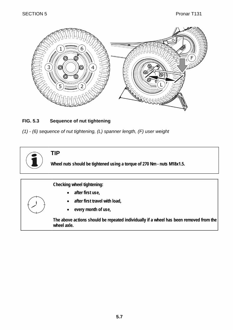
SECTION 5 Pronar T131
5.7
FIG. 5.3 Sequence of nut tightening
(1) - (6) sequence of nut tightening, (L) spanner length, (F) user weight
TIP
Wheel nuts should be tightened using a torque of 270 Nm - nuts M18x1.5.
Checking wheel tightening: • after first use,
• after first travel with load,
• every month of use,
The above actions should be repeated individually if a wheel has been removed from the wheel axle.

Pronar T131 SECTION 5
5.8
TAB. 5.1 Spanner arm
WHEEL TIGHTENING TORQUE BODY WEIGHT (F) ARM LENGTH (L)
[Nm] [kg] [m]
90 0.30
77 0.35
67 0.40 270
60 0.45
IMPORTANT!
Axle nuts may not be tightened with impact wrench, because of danger of exceeding permissible tightening torque, the consequence of which may be breaking the thread connection or breaking off the hub pins. The greatest precision is achieved by use of a torque spanner. Before commencing work, ensure that correct tightening torque value is set.
5.2.5 CHECK AIR PRESSURE, EVALUATE TECHNICAL CONDITION OF WHEELS AND TYRES
Tyre pressure should be checked each time after changing spare wheel and not less than
every month. In the event of intensive use it is recommended to check air pressure more
frequently. During this time sand spreader must be unloaded. Checking should be done
before travelling when tyres are not heated, or after an extended period of parking.
TIP
Tyre pressure values are specified in information decal, placed on wheel or on frame above machine wheel.
DANGER
Damaged tyres or wheels may be the cause of a serious accident.

SECTION 5 Pronar T131
5.9
While checking pressure pay attention to technical condition of wheels and tyres. Look
carefully at tyre sides and check the condition of tread.
In case of mechanical damage consult the nearest tyre service and check whether the tyre
defect requires tyre replacement.
Wheels should be inspected with regard to distortion, breaking of material, breaking of welds,
corrosion, especially in the area of welds and contact with tyre.
Proper technical condition and appropriate maintenance of wheels significantly extends the
life of these components and ensures appropriate level of safety to sand spreader users.
Checking tyre pressure and steel rims: • every 1 month of use,
• every week during intensive work,
• if needed.
5.2.6 MECHANICAL BRAKES ADJUSTMENT
During sand spreader operation drum brake linings are subjected to wear. Piston stroke
extends, and exceeding braking force limiting value declines.
Adjustment must be made when:
• piston stroke amounts to 2/3 of maximum stroke,
• expansion levers are not set in parallel to each other during braking,
• repairs are made to braking system.
Sand spreader wheels must brake simultaneously. Brakes adjustment involves changing the
position of the expander arm (1), Figure (5.4), in relation to expander shaft (2).
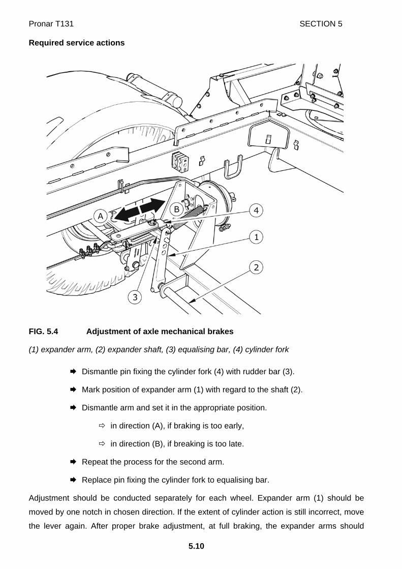
Pronar T131 SECTION 5
5.10
Required service actions
FIG. 5.4 Adjustment of axle mechanical brakes
(1) expander arm, (2) expander shaft, (3) equalising bar, (4) cylinder fork
Dismantle pin fixing the cylinder fork (4) with rudder bar (3).
Mark position of expander arm (1) with regard to the shaft (2).
Dismantle arm and set it in the appropriate position.
in direction (A), if braking is too early,
in direction (B), if breaking is too late.
Repeat the process for the second arm.
Replace pin fixing the cylinder fork to equalising bar.
Adjustment should be conducted separately for each wheel. Expander arm (1) should be
moved by one notch in chosen direction. If the extent of cylinder action is still incorrect, move
the lever again. After proper brake adjustment, at full braking, the expander arms should

SECTION 5 Pronar T131
5.11
create the angle of 90° with the cylinder piston, and the stroke should amount to
approximately half the length of the total stroke of the piston. After the brake is released,
expander arms may not be supported on any structural elements, because insufficient
withdrawal of a piston ram may cause abrasion of brake shoes in drum and result in
overheating sand spreader brakes. Expander arms must be positioned in parallel with regard
to each other at full braking. If this is not so, adjust the position of the lever, which has the
longer stroke.
If it is necessary to dismantle the equalising bar, remember or mark its original position in the
expander arms. The mounting position is selected by the Manufacturer and may not be
changed.
5.2.7 CHANGE OF PARKING BRAKE CABLE AND ADJUSTMENT OF CABLE TENSION.
Proper operation of the parking brake is dependent on the effectiveness of the axle brake
and the correct brake cable tension.
Replacing the parking brake cable
Hitch sand spreader to tractor. Park sand spreader and tractor on level
surface.
Place chocks under sand spreader wheel.
Loosen nuts (2) of cable clamps.
Dismantle cable (3).
Lubricate parking brake mechanism (1) and pins of cable guide rollers (4).
Install new cable, adjust cable tension.

Pronar T131 SECTION 5
5.12
FIG. 5.5 Adjustment of parking brake cable tension
(1) brake crank mechanism, (2) cable clamp nuts (3) hand brake cable, (4) guide roller
Adjustment of parking brake cable tension
Hitch sand spreader to tractor. Park sand spreader and tractor on level
surface.
Place chocks under sand spreader wheel.
Unscrew the brake mechanism bolt maximally (1) – Figure (5.5), (anti
clockwise).
Loosen nuts of handbrake cable clamps (2).
Tighten cable and tighten clamps.
Length of parking brake cable should be so selected that at total
release of working and parking brake the cable would be loose and
hanging by 1 - 2 cm.
Adjustment of parking brake cable tension should be conducted in the event of:
• stretching of cable,

SECTION 5 Pronar T131
5.13
• loosening of parking brake cable clamps
• after adjustment of axle brakes,
• after repairs to axle brake system,
• after repairs in parking brake system.
Before commencing adjustment make certain that the main break is correctly regulated and
is functioning properly.
Checking and parking brake adjustment: • every 12 months,
• if needed.
5.3 PNEUMATIC SYSTEM MAINTENANCE
5.3.1 PRELIMINARY INFORMATION
Work connected with the repair, change or regeneration of system components (brake
cylinders, lines, control valve, braking force regulator etc.) should be entrusted to specialist
establishments, having the appropriate technology and qualifications for this type of work.
The duties of the operator connected with the pneumatic system include:
• inspecting and checking air tightness of system.
• cleaning the air filter (filters),
• draining water from air tank,
• cleaning drain valve,
• cleaning and maintaining pneumatic line connections,
DANGER
Do NOT use the sand spreader when brake system is unreliable.

Pronar T131 SECTION 5
5.14
5.3.2 INSPECTING AND CHECKING AIR TIGHTNESS OF PNEUMATIC SYSTEM.
Checking hydraulic system tightness
Hitch sand spreader to tractor.
Immobilise tractor and sand spreader with parking brake. Place chocks under
sand spreader wheel.
Start tractor in order to supplement air in sand spreader brake system tank.
In single line systems air pressure should amount to approx. 5.8 bar.
In double line systems air pressure should amount to approx. 8 bar.
Turn off tractor ignition.
Check system components by releasing brake pedal in tractor.
Give particular attention to line connections and brake cylinders.
Repeat system check with depressed tractor brake pedal.
The help of a second person is required.
In the event of the appearance of leaks, compressed air will reach places of damage on the
exterior, with a characteristic hiss. Lack of system tightness may be exposed by covering
checked elements with washing fluid or other foaming preparations, which will not react
aggressively with system components. It is recommended to supply preparations
commercially available designed to facilitate discovering air leaks. Damaged components
should be replaced or repaired. If leaks appear at connections then tighten the connections. If
air continues to escape replace connection component or seal.
Check system tightness • after travelling the first 1,000 km,
• each time after making repairs or changing system components,
• annually.
Visual assessment of system
During tightness inspection attention should additionally be given to technical condition and
degree of cleanness of the system components. Contact of pneumatic line seals etc. with oil,

SECTION 5 Pronar T131
5.15
grease, petrol etc. may cause damage and accelerate the ageing process. Bent lines,
permanently deformed, cut or worn should be replaced.
Visual assessment of system • Conduct inspection of system at the same time as when checking tightness.
IMPORTANT!
Repair, exchange or regeneration of pneumatic system components may only be performed in a specialised workshop.
5.3.3 CLEANING THE AIR FILTERS
Depending on sand spreader working conditions, but not less than once in three months,
take out and clean air filter inserts, which are located in pneumatic system connection lines.
Inserts are used many times and are not subject to changing unless they are mechanically
damaged.
FIG. 5.6 Air filter
(1) securing slide lock, (2) air filter cover

Pronar T131 SECTION 5
5.16
DANGER
Before proceeding to dismantle filter, reduce pressure in supply line. While disengaging filter slide gate, hold cover with other hand. Stand away from filter cover vertical direction.
Required service actions
Reduce pressure in supply line.
Reduction of pressuring line may be achieved by pressing the head of
the pneumatic connection to resistance point.
Remove securing slide (1).
Hold the filter cover (2) with the other hand. After removing slide lock,
the cover is pushed off by the spring, in the filter housing.
The insert and the filter body should be carefully washed out and blown
through with compressed air. Assembly should be done in reverse order.
Cleaning the air filter (filters): • every 3 months of use,

SECTION 5 Pronar T131
5.17
5.3.4 DRAINING WATER FROM AIR TANK
FIG. 5.7 Draining water from air tank
(1) drain valve, (2) air tank
Required service actions
Open out drain valve (1) placed in lower part of tank (2) – the tank is placed on
brackets of left longitudinal member of lower frame.
The compressed air in the tank causes the removal of water to the
exterior.
After release valve stem should automatically close and stop airflow from tank.
In the event, that the valve stem resists returning to its setting, then
the whole drain valve must be unscrewed and cleaned, or replaced (if
it is damaged).

Pronar T131 SECTION 5
5.18
Draining water from air tank: • every seven days of use.
5.3.5 CLEANING DRAIN VALVE
DANGER
Before dismantling drain valve release air from tank.
Required service actions
Reduce pressure in air tank.
Reduction of pressure in tank is achieved by tilting the drain valve
mandrel.
Unscrew valve.
Clean valve, purge with compressed air.
Change copper seal.
Screw in valve, fill air tank, and check tank tightness.
Cleaning valve: • every 12 months (before winter period).
5.3.6 CLEANING AND MAINTAINING PNEUMATIC LINE CONNECTIONS AND PNEUMATIC SOCKETS
DANGER
Unreliable and dirty sand spreader connections may cause unreliability and faulty functioning of braking system.

SECTION 5 Pronar T131
5.19
Connection with damaged body should be replaced. In event of damage to cover or seal,
change these elements for new reliable elements. Contact of pneumatic connector seals with
oils, grease, petrol etc. may cause damage and accelerate ageing process.
If the sand spreader is unhitched from the tractor, connections should be protected by cover
or placed in their designated socket. Before the winter period it is recommended to preserve
the seal with special preparations (e.g. silicon grease for rubber elements).
Each time before connection of the machine inspect technical condition and cleanness of
contacts and sockets in tractor. If necessary clean or repair tractor socket.
Inspect sand spreader connections: • each time before hitching to tractor.
5.4 HYDRAULIC SYSTEM OPERATION
5.4.1 PRELIMINARY INFORMATION
Work connected with the repair, replacement or regeneration of hydraulic system
components should be entrusted to specialist establishments, having the appropriate
technology and qualifications for this type of work.
TIP
Bleeding air from the sand spreader's hydraulic system is not required during normal operation.
The duties of the operator connected with the hydraulic system include:
• inspecting and checking air tightness of system.
• Checking technical condition of hydraulic connections.
5.4.2 CHECKING HYDRAULIC SYSTEM TIGHTNESS
Required service actions
Hitch sand spreader to tractor.
Connect all hydraulic system lines according to service instructions.

Pronar T131 SECTION 5
5.20
Clean connectors and ram cylinders.
Run the sand spreader hydraulic system for a period of 5 minutes.
Check the system components for leaks.
If leaks appear at connections then tighten the connections.
Checking tightness: • After a week of use
• every 12 months of use.
5.4.3 CHECKING TECHNICAL CONDITION OF HYDRAULIC CONNECTIONS AND SOCKETS.
Hydraulic connections must be technically reliable and kept in a clean condition. Each time
before connecting, check if socket in tractor are maintained in good working condition.
Hydraulic systems of the tractor and sand spreader are sensitive to the presence of
particulate matter, which may cause damage to precision system components.
Inspection of hydraulic connections and sockets: • each time before connecting sand spreader to tractor.
5.4.4 REPLACE THE HYDRAULIC LINES
Hydraulic lines must be changed every 4 years regardless of their technical condition. This
should be entrusted to specialised workshops.
Replace the hydraulic lines: • every 4 years,

SECTION 5 Pronar T131
5.21
5.5 LUBRICATING THE SAND SPREADER
Sand spreader lubrication should be performed with the aid of a manually or foot operated
grease gun, filled recommended grease. Before commencing work insofar as is possible
remove old grease and other contamination. Remove and wipe off excess oil or grease.
Parts, which should be lubricated with machine oil, should be wiped with dry cleaning cloth
and then a small quantity of oil should be applied do surfaces (with oil can or brush). Wipe off
excess oil.
Change of grease in hub bearings should be entrusted to specialised service points,
equipped with the appropriate tools. According to the recommendations of the axle
Manufacturer, dismantle the entire hub, remove the bearing and individual sealing rings. After
careful washing and inspection mount lubricated elements. If necessary, bearing and seals
should be replaced with new parts. Lubrication of axle bearings shall be performed at least
once in 2 years.
Empty grease or oil containers should be disposed of according to the recommendations of
the lubricant Manufacturer.
TAB. 5.2 Sand spreader lubrication schedule
ITEM LUBRICATION POINT
NU
MB
ER O
F LU
BR
ICA
TIO
N
POIN
TS
TYPE
OF
GR
EASE
FREQ
UEN
CY
1 Handbrake crank mechanism 1 A 3M
2 Wheel bearings 2 A 23M
3 Pulley pin 1 A 6M
4 Equalising bar socket 2 A 3M
5 Support screw 1 A 6M
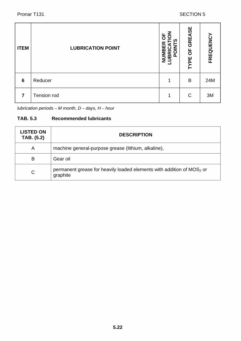
Pronar T131 SECTION 5
5.22
ITEM LUBRICATION POINT
NU
MB
ER O
F LU
BR
ICA
TIO
N
POIN
TS
TYPE
OF
GR
EASE
FREQ
UEN
CY
6 Reducer 1 B 24M
7 Tension rod 1 C 3M
lubrication periods – M month, D – days, H – hour
TAB. 5.3 Recommended lubricants
LISTED ON TAB. (5.2) DESCRIPTION
A machine general-purpose grease (lithium, alkaline),
B Gear oil
C permanent grease for heavily loaded elements with addition of MOS2 or graphite

SECTION 5 Pronar T131
5.23
FIG. 5.8 Lubrication points on the sand spreader
During sand spreader use the user is obliged to observe lubrication instructions according to attached lubrication schedule.
5.6 CONSUMABLES
5.6.1 HYDRAULIC OIL
Always adhere to the principle that the oil in the sand spreader hydraulic system and in the
tractor hydraulic system are of the same type. In the event of application of different types of
oil make certain that both hydraulic substances may be mixed together. Application of
different oil types may cause damage to sand spreader or tractor. In a new machine, the
hydraulic system is filled with L HL32 Lotos hydraulic oil.

Pronar T131 SECTION 5
5.24
TAB. 5.4 L-HL 32 Lotos hydraulic oil characteristics
ITEM NAME UNIT VALUE
1 ISO 3448VG viscosity classification - 32
2 Kinematic viscosity at 40°C mm2/s 28.8 – 35.2
3 ISO 6743/99 quality classification - HL
4 DIN 51502 quality classification - HL
5 Flash-point C 230
In the event of necessity of changing hydraulic oil for another oil, check the recommendations
of the oil Manufacturer very carefully. If it is recommended to flush the system with the
appropriate preparation, then comply with these recommendations. Attention should be
given, so that chemical substances used for this purpose do not damage the materials of the
hydraulic system. During normal sand spreader use change of hydraulic oil is not necessary,
but if required, this operation should be entrusted to a specialist service point.
Because of its composition the oil applied is not classified as a dangerous substance,
however long-term action on the skin or eyes may cause irritation. In the event of contact of
oil with skin wash the place of contact with water and soap. Do NOT apply organic solvents
(petrol, kerosene). Contaminated clothing should be changed to prevent access of oil to skin.
In the event of contact of oil with eye, rinse with large quantity of water and in the event of the
occurrence of irritation consult a doctor. Hydraulic oil in normal conditions is not harmful to
the respiratory tract. A hazard only occurs when oil is strongly atomised (oil vapour), or in the
case of fire during which toxic compounds may be released.
DANGER
Oil fires should be quenched with the use of carbon dioxide, foam or extinguisher steam. Do not use water to quench oil fires.
5.6.2 LUBRICANTS
For parts under great load it is recommended to apply lithium grease with molybdenum
disulphide (MOS2) or graphite additive. In the case of less loaded sub-assemblies the
application of general purpose machine greases is recommended, which contain
anticorrosion additive and have significant resistance to being washed away by water. Similar

SECTION 5 Pronar T131
5.25
characteristics should typify aerosol preparations (Silicon greases and anticorrosive lubricant
substances).
Before starting to use greases acquaint oneself with the content off the information leaflet for
the chosen product. Particularly relevant are safety rules and handling procedures for given
lubricant product and waste utilisation (used containers, contaminated rags etc.). Information
leaflet (material safety data sheet) should be kept together with grease.
5.7 TRANSMISSION MAINTENANCE
IMPORTANT!
If the amount of transmission oil added in order to reach the correct level (after 100 hours) is greater than 1.5 litres, it is an indication of transmission oil leakage. Please contact the service centre for repair.
TAB. 5.5 Requirements for transmission lube oil
ITEM NAME VALUE
1 SAE viscosity classification 80W/90
2 Kinematic viscosity at 100°C 14.0 – 20.0 mm²/s
3 Viscosity index, min 95
4 API quality class GL4
First oil change must be made after the first 100 hours worked. Replace oil in reduction gear
every 24 months or add in case of oil carry-over. Oil level should be checked regularly,
because in case of larger oil loss, repair of reduction gear seals may be necessary. Before
fresh oil is added, read the instructions of Manufacturer and make sure that rinsing of reducer
is not required. Supplement oil to required level (oil level indicator is located under inspection
glass on the reduction gear body). When changing the oil, also change the washers under
the plugs.
Check the oil level in the transmission each time before starting the machine. If oil level is insufficient, add oil.

Pronar T131 SECTION 5
5.26
IMPORTANT!
The temperature of the transmission housing may not exceed 80°C. If the transmission housing heats up too much, contact the service centre.
5.8 CLEANING THE SAND SPREADER
Sand spreader should be cleaned depending on requirements and before longer idle periods.
Wash sand spreader thoroughly each time after unloading the material, which may cause
corrosion of machine components. Before using pressure washer the user is obliged to
acquaint himself with the operating principles and recommendations concerning safe use of
this equipment.
Cleaning guidelines
• Remaining material should be removed from the load box before cleaning the
sand spreader (sweep or blow with compressed air).
• To clean the sand spreader only use clean running water or water with a cleaning
detergent additive with neutral pH.
• Using pressure washer increases washing effectiveness, but particular care must
be taken during work. During washing washer nozzle may not be closer than 50
cm from the surface being cleaned.
• Water temperature shall not exceed 55°C.
• Do not direct water stream directly at system and equipment elements of sand
spreader i.e. control valve, braking force regulator, brake cylinders, pneumatic,
electric and hydraulic plugs, lights, electrical connections, information and
warning decals, identification plates, line connections and lubrication points etc.
High water jet pressure may damage these elements.
• For cleaning and maintenance of plastic coated surfaces it is recommended to
use clean water or special preparations designed for this purpose.
• Do not apply organic solvents, preparations of unknown origin or other
substances, which may cause damage to lacquered, rubber or plastic surfaces. In
the event of doubt it is recommended to make a test on an unseen surface area.

SECTION 5 Pronar T131
5.27
• Surfaces smeared with oil or grease should be cleaned by application of benzene
or other degreasing agents and then washed with clean water with added
detergent. Comply with recommendations of the Manufacturer.
DANGER
Carefully read the instructions for application of washing detergents and maintenance preparations. While washing with detergents wear appropriate protective clothing and goggles protecting against splashing.
• Washing detergent should be kept in original containers, optionally in replacement
containers, but very clearly marked. Preparations may not be stored in food and
drink containers.
• Care for the cleanness of elastic lines and seals. The plastic from which these
elements are made may be susceptible to organic substances and some
detergents. As a result of long-term reaction of some substances, the ageing
process may be accelerated and risk of damage increased. Rubber elements
should be maintained with the aid of special preparations after previous thorough
washing.
• After finishing washing wait until the sand spreader is dry and then grease all
inspection points according to recommendations. Remove excess oil or grease
with a dry cloth.
• Observe environmental protection principles and wash the sand spreader in a
place designed for this purpose.
• Washing and drying sand spreader must take place at temperatures above 0°C.
• After washing and drying, sand spreader should be greased at all control points
regardless of last lubrication period.
5.9 STORAGE
After finishing work, the sand spreader should be thoroughly cleaned and washed with water
jet. In the event of damage to the paint coat, clean rust and dust from damaged area,
degrease and then paint with undercoat and after it is dry paint with surface coat paint
retaining colour uniformity and even thickness of protective coating. Until the time of touch-up

Pronar T131 SECTION 5
5.28
painting, the damaged place may be covered with a thin layer of grease or anticorrosion
preparation. Sand spreader should be kept in closed or roofed building at temperature above
0°C.
If the sand spreader will not be used for a long time, it is essential to protect it from adverse
weather, especially rust and accelerated tyre deterioration. During this time the machine must
be unloaded.
Sand spreader should be very carefully washed and dried. While washing do not direct a
strong water or steam jet at information and warning decals, bearings of the feeding table
rollers and bearings of the tightening mechanism, electrical equipment elements, and
hydraulic and pneumatic systems. Nozzle of pressure or steam washer should be kept at a
distance of not less than 30 cm from cleaned surface. Corroded areas should be protected as
described above.
Lubricate the sand spreader according to the instructions provided. In the event of prolonged
work stoppage, it is essential to lubricate all elements regardless of the period of the last
lubrication process.
Tyres should undergo conservation maintenance at least twice a year using the appropriate
preparations designed for this purpose. Wheels and tyres should be previously carefully
washed and dried. During longer storage of unused sand spreader it is recommended that
every 2 to 3 weeks the machine may be moved a bit so that the place of contact of tyres with
ground is changed. The tyres will not be deformed and maintain proper geometry. Also tyre
pressure should be inspected from time to time, and if necessary pressure should be
increased to appropriate value.

SECTION 5 Pronar T131
5.29
5.10 SETTING WORKING POSITION OF DRAWBAR
FIG. 5.9 Adjustment of drawbar position
(1) drawbar, (2) bolt, (3) drawbar linkage, (4) front plate (A), (B) permitted drawbar positions
In new sand spreader, adjust the position of drawbar to the tractor hitch. Changing height of
drawbar should be performed by two persons. In order to do this:
position the sand spreader on a flat surface, put chocks under the wheels,
using the knob, pull out or retract the support to such a height so that the sand
spreader frame is positioned parallel to the ground,
Unscrew the bolts (2) and remove the drawbar (1),
adjust the height of the drawbar by screwing it to the front plate (4) at the
desired height.
The mounting height and position of the drawbar should be individually matched to tractor
hitch.
DANGER
Changing height of drawbar should be performed by two persons. Take special care when removing the bolts because of the risk of crushing feet.

Pronar T131 SECTION 5
5.30
5.11 ADJUST CONVEYOR BELT TENSION
FIG. 5.10 Adjustment of conveyor belt tension
(1) bearing mechanism, (2) tensioning bolt, (3) adjustment nut
Adjustment of conveyor belt tension should be performed if decrease in spreading
mechanism efficiency is noticeable when flow regulator setting is unchanged. In such cases
the conveyor belt slips considerably while moving over driving roller of the drive mechanism.
Consequently, the conveyor belt wears faster and may be completely broken.
The conveyor belt should be tensioned symmetrically in such a manner as to ensure that
difference between distances (a) measured from the roller axis to the front part of bracket, on
both sides of the sand spreader, is not larger than 5 mm. Nuts (3) of the tightening
mechanism are located on the front wall of the load box. When the nut is turned clockwise,
bearing assembly (1) moves towards the front wall and tightens the conveyor belt. The length
of protruding end of tensioning bolt (2) should be the same on the left and right side of the
sand spreader. Equal lengths of protruding bolt ends indicate that the conveyor belt is
tightened symmetrically.
Conveyor belt tightening should be performed only when the load box is empty. Adjustment is
recommended to be carried out in the same conditions (the same ambient temperature).

SECTION 5 Pronar T131
5.31
5.12 ADJUST SPREADING DISC BLADES
Setting of rake angle of the adapter disc blades and adjustment of flow regulator setting have
influence on spread width. Blades are factory set in position (A).
In order to change rake angle:
loosen nuts located closer to the centre of disc,
undo the nuts and remove bolts from the external side of the disc,
set blades to selected position (A), (B) or (C),
install bolts and nuts, tighten all connections,
repeat the process for the second disc.
Blades in the left disc and right disc do not have to be set symmetrically. Variable spread
width is achieved in this way. For example, if blades in the right disc are set to position (C)
and blades in the left disc to position (A), the spread width on the right side of the sand
spreader will be larger.
FIG. 5.11 Changing rake angle of blades

Pronar T131 SECTION 5
5.32
(1) blade, (2) securing bolts, (A), (B), (C) allowable working positions of blades
IMPORTANT!
After change of blades position, check tightening of bolt connections after 8 hours of sand spreader operation.
5.13 TIGHTENING TORQUE FOR NUT AND BOLT CONNECTIONS
Unless other tightening parameters are given, during maintenance repair work apply
appropriate torque to tightening nut and bolt connections. Recommended tightening torque of
most frequently applied nut and bolt connections are given in table below. Given values apply
to non-lubricated steel bolts.
TAB. 5.6 Tightening torque for nut and bolt connections
5.8(1) 8.8(1) 10.9(1) THREAD METRIC Md [Nm]
M10 37 49 72
M12 64 85 125
M14 100 135 200
M16 160 210 310
M20 300 425 610
M24 530 730 1,050
M27 820 1,150 1,650
(1) – resistance class according to DIN ISO 898 standard
TIP
Hydraulic lines should be tightened with torque of 50 – 70 Nm.

SECTION 5 Pronar T131
5.33
FIG. 5.12 Bolt with metric thread
(1) resistance class, (d) thread diameter
5.14 TROUBLESHOOTING
TAB. 5.7 Troubleshooting
FAULT CAUSE REMEDY
Brake system pneumatic line not connected Connect brake line.
Damaged pneumatic system connection lines Replace
Leaking connections Tighten, replace washers or seal set
Parking brake applied Release parking brake
Problem with moving off
Damage control valve or brake force regulator
Check valve, check brake force regulator, replace in the event of damage to whichever elements
Excessive play in bearings Check play and regulate if needed Noise in axle hubs
Damaged bearing Change bearing together with sealing ring
Excessive heating of axle hubs
Incorrectly adjusted main brake Regulate setting of expander arms

Pronar T131 SECTION 5
5.34
FAULT CAUSE REMEDY
Incorrectly adjusted parking brake
Adjust tension of parking brake cables
Worn brake linings Change brake shoes
Flow regulator setting is 0 Increase setting
Conveyor belt is too slack Tighten the belt, possibly replace
Incorrectly connected hydraulic system lines Check and possibly correct
Damaged quick couplers of hydraulic system lines Replace quick couplers
Damaged check valve in hydraulic system Check and possibly replace
Conveyor belt does not move
Damaged flow regulator Check and possibly replace

NOTES
……………………………………………………………………………………………………………
……………………………………………………………………………………………………………
……………………………………………………………………………………………………………
……………………………………………………………………………………………………………
……………………………………………………………………………………………………………
……………………………………………………………………………………………………………
……………………………………………………………………………………………………………
……………………………………………………………………………………………………………
……………………………………………………………………………………………………………
……………………………………………………………………………………………………………
……………………………………………………………………………………………………………
……………………………………………………………………………………………………………
……………………………………………………………………………………………………………
……………………………………………………………………………………………………………
……………………………………………………………………………………………………………
……………………………………………………………………………………………………………
……………………………………………………………………………………………………………
……………………………………………………………………………………………………………
……………………………………………………………………………………………………………
……………………………………………………………………………………………………………
……………………………………………………………………………………………………………
……………………………………………………………………………………………………………
……………………………………………………………………………………………………………
……………………………………………………………………………………………………………

……………………………………………………………………………………………………………
……………………………………………………………………………………………………………
……………………………………………………………………………………………………………
……………………………………………………………………………………………………………
……………………………………………………………………………………………………………
……………………………………………………………………………………………………………
……………………………………………………………………………………………………………
……………………………………………………………………………………………………………
……………………………………………………………………………………………………………
……………………………………………………………………………………………………………
……………………………………………………………………………………………………………
……………………………………………………………………………………………………………
……………………………………………………………………………………………………………
……………………………………………………………………………………………………………
……………………………………………………………………………………………………………
……………………………………………………………………………………………………………
……………………………………………………………………………………………………………
……………………………………………………………………………………………………………
……………………………………………………………………………………………………………
……………………………………………………………………………………………………………
……………………………………………………………………………………………………………
……………………………………………………………………………………………………………
……………………………………………………………………………………………………………
……………………………………………………………………………………………………………
……………………………………………………………………………………………………………
……………………………………………………………………………………………………………
……………………………………………………………………………………………………………

ANNEX A
TYRES WHEEL RIM
11.5/80-15.3 14PR 139A8 9.00x15.3"