3136784-T16-REP Electrical Master Plan
53
Robertson Barracks Electrical Master Plan 3136784-T16-REP-00 Department of Defence August 2021 The Power of Commitment
Transcript of 3136784-T16-REP Electrical Master Plan

Robertson Barracks Electrical Master Plan 3136784-T16-REP-00
Department of Defence
August 2021
The Power of Commitment
The Power of Commitment
GHD Pty Ltd | ABN 39 008 488 373
24 Mitchell Street, Level 7
Darwin, Northern Territory 800, Australia
T +61 8 8982 0100 | F +61 8 8981 1075 | E [email protected] | ghd.com
Printed date 24/08/2021 1:42:00 PM
Last saved date 24 August 2021
File name https://projects.ghd.com/oc/Victoria2/defencerenewableener/Delivery/Documents/Tech/Task 16 - ROB HV Masterplan/3136784-T16-REP_Electrical Master Plan.docx
Author Erwan Goasdoue
Project manager Le Thuy Dinh
Client name Department of Defence
Project name Defence Renewable Energy Program Consultant
Document title Robertson Barracks Electrical Master Plan | 3136784-T16-REP-00
Revision version Rev 00
Project number 3136784
Document status
Status Code
Revision Author Reviewer Approved for issue
Name Signature Name Signature Date
Draft A E.Goasdoue
L.Benger
A.O’Keeffe A.O’Keeffe* A. Low A. Low* 22/06/2021
Final 00 E.Goasdoué L. Benger L. Benger* A. Low A. Low* 24/08/2021
© GHD 2021
This document is and shall remain the property of GHD. The document may only be used for the purpose for
which it was commissioned and in accordance with the Terms of Engagement for the commission. Unauthorised
use of this document in any form whatsoever is prohibited.
GHD | Department of Defence | 3136784 | Robertson Barracks Electrical Master Plan i
Executive Summary
Robertson Barracks is located approximately 15 km east of Darwin Business District (CBD) in the Northern
Territory. The barracks was built during the 1990s and is home to the 1st Brigade and the 1st Aviation Regiment.
The objective of this report is to develop an Electrical Master Plan for the high voltage (HV) primary network
(including backup generation) at Robertson Barracks until 2035. This report will address the future needs of the
establishment in terms of:
– Incoming electrical supply
– High Voltage (HV) Primary network configuration
– Emergency Generation
– Power Control and Monitoring Systems (PCMS)
Load Projection
The last three year’s peak load for Robertson Barracks were recorded as 9.59, 9.64 and 10.20 MVA, in February
2018, November 2019 and March 2020 respectively.
The Base load was projected out to 2035 using data about known future projects, and beyond this using a yearly
load growth of 3%. The Ultimate Base Load (UBL) is expected to reach 20.3 MVA (after diversity and with 2 MVA
solar PV offset) by 2035.
Incoming Supply Options
The existing incoming supply consists of four 11 kV feeders, one of which is a non-dedicated backup feeder. The
combined capacity of the four incoming feeders is 24.5 MVA or 17.8 MVA firm. This assumes that the load can be
spread evenly across the feeders which is not possible in practice particularly as the incoming supply originates
from two difference Zone Substations and results in difficult switching operation of the Base HV network to prevent
connecting these two Zone Substation together. A more realistic capacity is 80% of the combined capacity of the
feeders, which is 19.6 MVA or 14.2 MVA firm. To meet the projected demand the existing supply capacity will need
to be augmented.
Three supply options were identified and analysed to determine how best to address these issues:
– Option 1 is to continue to take electrical supply at 11 kV from the PWC Zone Substations at Palmerston
(PAZSS) (or Hudson Creek (HCTS) and Berrimah (BEZSS).
– Option 2 is to take electrical supply at 66 kV, with Defence owned 66/11 kV substations.
– Option 3 is to take electrical supply at 11 kV from a new PWC Zone Substation located on the boundary of
Robertson Barracks.
Option 2 is recommended as it offers the best flexibility and scalability. It is noted that Option 1 can be considered
an interim solution before a transition to Option 2 as it is quite inflexible as a long-term solution.
Master Plan
The recommended supply option is to ultimately take supply at 66 kV, with this supply coming from two different
sources. The proposed power system concept developed for this master plan is to modify the existing
configuration to align with the incoming supply by splitting the HV network into two separate systems with limited
interconnection:
– HVSYS-A: Consisting of the existing A Ring and new loads to the east of the main Base area.
– HVSYS-B: Consisting of the existing B and C rings and new loads to the north of the main Base area.
One of the two incoming supplies described above will be connected to one system and one to the other.
The CEPS buses will be located between the two systems so that it can supply each system separately of both
together. It will also act as a cross connect if mains supply to one system failed and the was still healthy.

GHD | Department of Defence | 3136784 | Robertson Barracks Electrical Master Plan ii
A high-capacity interconnector will also be provided between the two systems for use in the event of a failure at
one of the two 66 kV intake stations.
In addition, the recommended Master Plan envisages that the HV electrical system will include the following main
elements by 2035:
66 kV Configuration
A 66 kV intake will be located at both the new ISS1 and ISS2. Each intake will have capacity to supply the entire
Base and consist of:
– A 66 kV intake indoor switchboard
– A 66/11 kV 25/32 MVA power transformer
– The transformer will feed a 11 kV switchboard to which the 11 kV rings and interconnectors are connected
– A 66 kV interconnector that connects the 66 kV intakes at the new ISS1 and ISS2.
11 kV Configuration and PCMS
The Primary distribution system consists of a number of new primary distribution nodes as follow.
– Two new Intake Switching Stations (ISS):
• ISS1 – located adjacent to the existing ISS2.
This is where the incoming supply to HVSYS-A is connected
• ISS2 – located adjacent to the existing ISS3.
This is where the incoming supply to HVSYS-B is connected.
– HVSYS-A consists of ISS1 and two additional new Primary Switching Stations (PSS):
• PSS1 – located adjacent to the existing ISS1 at CEPS
• PSS4 – The new intake station located within the RCTA development and is currently being installed as
part of that project.
ISS1, PSS1 and PSS2 are connected together by three Interconnectors in a triangular arrangement.
– HVSYS-B consists of ISS2 and two additional new Primary Switching Stations (PSS):
• PSS2 – located adjacent to the existing ISS1 at CEPS
• PSS3 – located adjacent to the existing ISS2.
• PSS5 – A new switching station located north of Campbell Road to supply the future loads in that area.
• ISS2, PSS2 and PSS3 are connected together by three Interconnectors in a triangular arrangement.
• PSS5 will be supplied by an interconnector from ISS2
A high-capacity 11 kV interconnector will run between the adjacent nodes ISS1 and PSS3.
CEPS (existing consisting of two separate switchboards, CEPS1 and CEPS2). These are connected between
PSS1 and PSS2.
CEPS and PCMS
The CEPS will be augmented to allow for the Base load increase. By 2035 the overall CEPS capacity will be
11.6 MW.
A separate building immediately behind the existing CEPS is proposed, consisting of:
– A single generating hall with space for three generating sets
– A control room
– Ancillary rooms, such as a workshop and storage facility
Additional bulk fuel storage will be provided adjacent to the new building, and probably consist of above-ground
self-bunded tanks.
The PCMS shall be upgraded to allow for data logging and monitoring of the HV network (HV CB) as well as
distribution substation LV incomer.

GHD | Department of Defence | 3136784 | Robertson Barracks Electrical Master Plan iii
Contents
Executive Summary i
1. Introduction 1
1.1 Purpose of this report 1
1.1.1 General 1
1.1.2 HV network 1
1.2 Scope and limitations 1
1.3 Assumptions 2
2. Existing installation 3
2.1 Channel Island Power Station and Weddell Power Station 3
2.2 Hudson Creek Terminal Substation 4
2.2.1 Configuration 4
2.2.2 Condition 4
2.2.3 Reliability and redundancy 4
2.2.4 Capacity 5
2.3 Berrimah Zone Substation 5
2.3.1 Condition 6
2.3.2 Reliability and redundancy 6
2.3.3 Capacity 6
2.4 Palmerston Zone Substation 6
2.4.1 Condition 7
2.4.2 Reliability and redundancy 7
2.5 DNSP supply to Robertson Barracks 8
2.5.1 Configuration 8
2.5.2 Condition 9
2.5.3 Reliability and redundancy 9
2.5.4 Number of unplanned outages 9
2.5.5 Duration of unplanned outages 10
2.6 Existing loads 10
2.6.1 Magnitude and power factor 10
2.6.2 Load distribution 11
2.6.3 Load profile 11
2.6.4 Power factor 12
2.7 Primary distribution 12
2.7.1 Configuration 12
2.7.2 Capacity 14
2.7.3 Condition 15
2.7.4 Reliability and redundancy 15
2.8 Incoming supply – Solar 15
2.8.1 Configuration 15
2.8.2 Commercial agreement 15
2.9 Central Emergency Power Station (CEPS) 16
2.9.1 Configuration 16
2.9.2 Capacity 16
2.9.3 Condition 16
2.9.4 Reliability and redundancy 16
2.10 Local Emergency Generators (LEGs) 17

GHD | Department of Defence | 3136784 | Robertson Barracks Electrical Master Plan iv
2.10.1 Configuration 17
2.10.2 Condition 17
2.11 Power Control and Monitoring System (PCMS) 17
2.11.1 Configuration 17
2.11.2 Condition 17
2.12 BEAP report and HV assessment report 18
3. Projected Base Loads 19
3.1 Existing Load 19
3.2 Proposed Projects 19
3.2.1 Land 121 – armoured fighting vehicle – implementation 2020 19
3.2.2 HQ1 Barracks project – implementation 2020 19
3.2.3 AZ5950 - Power Purchase Agreement for Energy (solar) NT 2022 19
3.2.4 EST01990 – NT Range WP11 – implementation 2021 19
3.2.5 Land 2110 Phase 1B – implementation 2022 19
3.2.6 EST01990 – MEFH Building services ranges, training camp & range control precinct – implementation 2022 19
3.2.7 EST02116 - Robertson Barracks MTR – implementation 2024 20
3.2.8 EST05064 - USFPI Base Support Infrastructure – implementation 2024 20
3.2.9 Land 154 Ph-4 – implementation 2024 20
3.2.10 Land 8120 Ph-1 – implementation 2025 21
3.2.11 Land 4503 Ph-1 – implementation 2028 21
3.2.12 JP9101 - Relocation of HF antenna array – implementation date unknown 21
3.2.13 Robertson Barracks north side Masterplanning – implementation date unknown 21
3.3 Electric Vehicle Charging Stations 21
3.4 Growth in Existing Load – 2021 to 2035 21
3.5 Ultimate Base Load 22
3.6 Ultimate Design Load 22
4. Electrical Supply Options 23
4.1 Required Supply Capacity 23
4.2 Option Descriptions 23
4.2.1 Option 1 – Continue to take electrical supply at 11 kV 23
4.2.2 Option 2 – Take electrical supply at 66 kV 25
4.2.3 Option 3 – Take electrical supply at 11 kV from a new ZSS 26
4.3 Evaluation of Supply Options 26
4.3.1 Evaluation Criteria 26
4.3.2 Technical Viability 26
4.3.3 Scalability 27
4.3.4 Timescale 28
4.3.5 Capital and running costs 29
4.3.6 Recommendation 30
5. Electrical Master Plan 31
5.1 Power System Concept 31
5.2 Primary Power Distribution System 31
5.2.1 Proposed Configuration 31
5.3 Secondary Power Distribution System (Rings) 33
5.3.1 Number of Rings 33
5.3.2 Replacement of Ringmains Cables 33
5.4 Incoming supply – Solar 34
5.5 Emergency Power Generation 34
5.5.1 CEPS Capacity 34

GHD | Department of Defence | 3136784 | Robertson Barracks Electrical Master Plan v
5.5.2 Proposed CEPS Configuration 34
5.5.3 New CEPS Generator Control System (GCS) 34
5.6 Power Control and Monitoring System 35
5.6.1 Monitoring Functions 35
5.6.2 LV Load Shedding 35
5.6.3 Local Emergency Generators (LEGs) 36
5.7 Preliminary trade pricing estimate 36
6. References 38
6.1 Referenced Documents 38
6.2 Abbreviations 38
Table index
Table 1 Base peak demand 2007 and 2017-2020 11
Table 2 HV ring load distribution 11
Table 3 Preliminary trade pricing estimate 37
Figure index
Figure 1 PWC Darwin-Katherine network diagram 3
Figure 2 Berrimah Zone Substation single line diagram 5
Figure 3 Palmerston Zone Substation single line diagram 7
Figure 4 Incoming feeder arrangement 9
Figure 5 July 2019 to June 2020 Base power demand and average power factor (PF) 12
Figure 6 Existing HV network arrangement 14
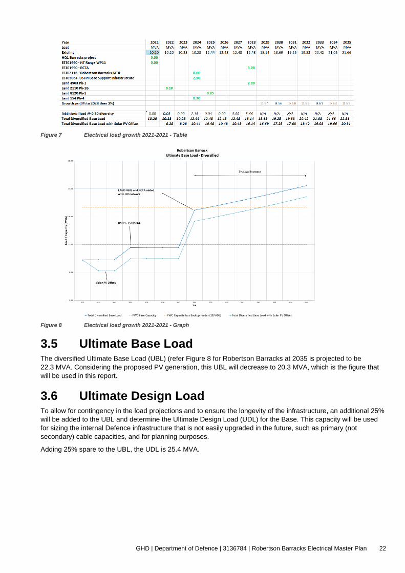
Figure 7 Electrical load growth 2021-2021 - Table 22
Figure 8 Electrical load growth 2021-2021 - Graph 22
Figure 9 Option 1 – Proposed arrangement 25
Figure 10 Option 2 – Proposed arrangement 26
Appendices
Appendix A Drawings

GHD | Department of Defence | 3136784 | Robertson Barracks Electrical Master Plan 1
1. Introduction
Robertson Barracks is located approximately 15 km east of Darwin Business District (CBD) in the Northern
Territory. The barracks was built during the 1990s and is home to the 1st Brigade and the 1st Aviation Regiment.
Robertson Barracks also homes US Marines on a six-month rotational basis.
1.1 Purpose of this report
1.1.1 General The purpose of this electrical master plan (EMP) is to address the future needs of the establishment in terms of the
following:
– Incoming electrical supply
– High Voltage (HV) distribution for the primary network only
– Emergency generation
– Power Control and Monitoring Systems (PCMS).
The report aims to provide a reference framework for future development, to allow the high voltage (and backup
generation) infrastructure to adequately meet the needs of the Base until 2035. In doing so, capacity constraints or
redundant infrastructure may be avoided.
This master plan has been prepared using the guidelines of the MIEE 2011 (Amendment 3) and electrical
principles developed by GHD in consultation with Defence in a number of similar master plans for Defence
establishments.
1.1.2 HV network
While there is some preliminary information about the electrical loads for some of the proposed development, the
actual site of such development is not known. Therefore, due to the lack of information with regards to the new
projects loads, their nature and location, Defence Directorate Estate Engineering Policy (DEEP) has agreed that
this EMP would consider the HV primary network only. The configuration of the secondary network (e.g., HV rings)
will not be considered as part of this EMP.
1.2 Scope and limitations This report: has been prepared by GHD for Department of Defence and may only be used and relied on by
Department of Defence for the purpose agreed between GHD and the Department of Defence as set out in section
1.1 of this report.
GHD otherwise disclaims responsibility to any person other than Department of Defence arising in connection with
this report. GHD also excludes implied warranties and conditions, to the extent legally permissible.
The services undertaken by GHD in connection with preparing this report were limited to those specifically detailed
in the report and are subject to the scope limitations set out in the report.
The opinions, conclusions and any recommendations in this report are based on conditions encountered and
information reviewed at the date of preparation of the report. GHD has no responsibility or obligation to update this
report to account for events or changes occurring subsequent to the date that the report was prepared.
The opinions, conclusions and any recommendations in this report are based on assumptions made by GHD
described in this report (refer section 1.3. of this report). GHD disclaims liability arising from any of the
assumptions being incorrect.
GHD has prepared this report on the basis of information provided by Department of Defence and others who
provided information to GHD (including Government authorities), which GHD has not independently verified or
checked beyond the agreed scope of work. GHD does not accept liability in connection with such unverified

GHD | Department of Defence | 3136784 | Robertson Barracks Electrical Master Plan 2
information, including errors and omissions in the report which were caused by errors or omissions in that
information.
1.3 Assumptions A number of assumptions have been made in the preparation of this report. These are listed in the applicable
sections of this report.

GHD | Department of Defence | 3136784 | Robertson Barracks Electrical Master Plan 3
2. Existing installation
The Power and Water Corporation (PWC) is the Distribution Network Service Provider (DNSP) for this region. The
electrical supply for Robertson Barracks is taken from 11 kV feeders originating at the PWC Berrimah Zone
Substation and Palmerston Zone Substation.
The aim of the following section is to identify potential shortfall within the PWC network resulting from the HV
network upgrade at Robertson Barracks.
2.1 Channel Island Power Station and Weddell Power Station
Channel Island Power Station (CIPS) is the largest power station in the Northern Territory, first commissioned in
1986 and the main source of electricity for the Darwin-Katherine Interconnected system. CIPS houses five (5 off)
turbines (gas/diesel), one (1 off) steam turbine and three (3 off) aero derivative turbines (gas/diesel), with a total
combined capacity of 310 MW.
The total MW availability is going to reduce from 310 MW to 279 MW following the decommissioning of one of its
units (C3).
Weddell Power Station (WPS) is a 129 MW power station consisting of two open cycle gas turbines commissioned
in 2008, with a third commissioned in 2014. WPS also feeds the Darwin-Katherine power network.
The PWC network diagram is shown in Figure 1.
Figure 1 PWC Darwin-Katherine network diagram

GHD | Department of Defence | 3136784 | Robertson Barracks Electrical Master Plan 4
2.2 Hudson Creek Terminal Substation
2.2.1 Configuration
The Hudson Creek Terminal Substation (HCTS) is fed from CIPS via two (2 off) 132 kV transmission lines. HCTS
houses three (3 off) 132/66 kV power transformers. Two (2 off) 66 kV lines feed Berrimah Zone Substation (BZSS)
and one (1 off) 66 kV line connects to Palmerston Zone Substation (PZSS).
2.2.2 Condition The CIPS to HCTS 132 kV transmission lines are in relatively good condition. A current program of works
undertaken by PWC plans to address the corrosion issues with the transmission lines insulators by replacing them.
This is considered crucial for the security of the network.
The high voltage circuit breakers at HCTS are reaching end of life and have a history of moisture entering the
active parts, increasing the risk of circuit breaker failure. PWC plans to address the issue by replacing all circuit
breakers at HCTS.
2.2.3 Reliability and redundancy
Reliability
The outages on the Darwin to Katherine power system are the main cause of supply interruption within the
network. This is particularly the case in the Wet Season when lightning activity is high as Darwin has some of the
highest rates of lightning strike in the world.
Although the Darwin-Katherine power network mainly consists of overhead distribution lines, the network has been
designed to cater for these lightning strikes in order to limit supply interruptions.
In addition to regular lightning induced outages during the Wet Season, severe tropical cyclone events in the
Darwin area have the potential to affect power supply reliability.
In 2019-2020, PWC met the reliability metrics target imposed by the NT Electricity Industry Performance Code
(EIP Code).
The System Average Interruption Duration Index (SAIDI in minutes of interruption experience per customer) was
53.4 minutes against a target of 140 minutes in a year.
The System Average Interruption Frequency Index (SAIFI in number of interruption experience per customer) was
0.97 interruption against a target of 2 interruptions in a year.
Redundancy
There is some redundancy in the incoming mains supply to HCTS:
– The CIPS 132 kV transmission line and the HCS 66 kV distribution line are both double circuit
– In the event that any generating set at CIPS is out of service, HCTS can be fed from WPS. Additional capacity
for Robertson Barracks can be taken from the Weddell Power Station via 66 kV transmission lines from
Archer Zone Substation
The HCTS has a current N-2 capacity (i.e., when two of the three 125 MVA transformer fail) of 127.5 MVA. PWC
has identified that under this scenario, the HCTS would be 13.62 MVA overloaded by 2021, increasing to
77.24 MVA by 2027. PWC indicates that the preferred solution is to purchase a spare 132/66 kV power
transformer.

GHD | Department of Defence | 3136784 | Robertson Barracks Electrical Master Plan 5
2.2.4 Capacity When considering the electrical supply to the Base, two different capacities shall be considered:
Capacity: The Capacity of the network is the sum of the individual capacities of the individual components
Firm Capacity: The Firm Capacity of the network is the Capacity of the network with the largest component out of
service.
Overhead line - CIPS to HCTS
Maximum Capacity: 532 MVA Rated capacity (Line 1 and Line 2 of 266 MVA)
– Firm Capacity: 266 MVA (with only one transformer out of service)
– Total Maximum demand: 182 MVA (as of 2020)
Under N-1 scenario, there is 84 MVA spare capacity to feed HCTS.
HCTS
– Maximum Capacity: 375 MVA Rated capacity (Tx1, Tx2 and Tx3 of 125 MVA)
– Tx Firm Capacity: 250 MVA (with only one transformer out of service)
– Total Maximum demand: 141 MVA (as of 2021)
Under N-1 scenario, the HCTS has 109 MVA spare capacity.
2.3 Berrimah Zone Substation Electrical supply to Berrimah Zone Substation (BEZSS) originates at the HCTS via two 66 kV distribution line.
Each 66 kV feeder terminates onto a dedicated 66 kV bus which feeds a 66/11 kV 38.1 MVA power transformer.
The BEZSS single line diagram is shown in Figure 2 below.
Figure 2 Berrimah Zone Substation single line diagram

GHD | Department of Defence | 3136784 | Robertson Barracks Electrical Master Plan 6
2.3.1 Condition The assets in BEZSS are at the end of their serviceable life. The 66 kV oil circuit breakers are in poor condition
and can cause significant damage to adjacent equipment when they fail.
PWC has also indicated that safety issues exist with the 11 kV switchboard.
An option analysis undertaken by PWC indicates that a new zone substation located adjacent to the existing
BEZSS is the preferred option to address these issues. PWC have an imminent project to construct this substation
by 2024. The new substation will be named Trevor Horman ZSS (THZSS).
2.3.2 Reliability and redundancy
Reliability
Despite the aging equipment, there is no indication of reliability issue at BEZSS.
Redundancy
There is some redundancy at BEZSS:
– Two 66 kV circuits from HCTS feed two independent 66 kV buses
– Two 66/11 kV transformers feed two independent 11 kV buses
However, despite the redundancies indicated above, Robertson Barracks is fed via only one 11 kV feeder from the
BEZSS.
2.3.3 Capacity
Overhead line - HCTS to BEZSS
– Maximum Capacity: 132 MVA Rated capacity (Line 1 and Line 2 of 64 MVA)
– Firm Capacity: 64 MVA
– Total Maximum demand: 27 MVA (as of 2020)
Under N-1 scenario, there is 37 MVA spare capacity to feed BEZSS via HCTS-BEZSS lines. The consideration for
other feeding scenario (such as Lenyard Zone Substation ) is dependent upon PWC switching configuration and is
not part of this EMP scope.
– BEZSS
– Maximum Capacity: 76.2 MVA (Tx1 and TZ2 of 38.1 MVA)
– Firm Capacity: 38.1 MVA
– Total Maximum demand: 26.1 MVA in 2018/19
Under N-1 scenario, the BEZSS has 12 MVA spare capacity.
2.4 Palmerston Zone Substation Electrical supply to the Palmerston Zone Substation (PAZSS) primarily originates from CIPS and is distributed via
a single 66 kV line from HCTS.
Backup electrical supply is available from Weddell Power Station (WPS), where it is distributed through a double
66 kV line to Archer Zone Substation, and then to Palmerston Zone Substation through a single 66 kV line.
The PAZSS single line diagram is shown in Figure 3.

GHD | Department of Defence | 3136784 | Robertson Barracks Electrical Master Plan 7
Figure 3 Palmerston Zone Substation single line diagram
2.4.1 Condition
The assets in PAZSS are at the end of their serviceable life. The 66 kV oil circuit breakers are in poor condition
and can cause significant damage to adjacent equipment when they fail.
2.4.2 Reliability and redundancy
Reliability
Despite the aging equipment, there is no indication of reliability issue at PAZSS.
Redundancy
There is some limited redundancy at PAZSS:
– Two 66 kV circuits (HCTS and Archer Zone Substation) feed two independent 66 kV buses
– Two 66/11 kV transformers feed two independent 11 kV buses
PWC has identified a future overload occurring on the HCTS to Archer Zone Substation (ARZSS) 66 kV line if the
HCTS to PAZSS 66 kV line is out of service, and vice versa. Under such N-1 scenario, the overload planned on
the 66 kV line from HCTS to Archer Zone Substation is expected to exceed capacity by 5.82 MVA and the HCTS
to PAZSS is expected to exceed capacity by 4.68 MVA by 2029.
PWC is currently exploring the option to increase both 66 kV line capacity from 64 MVA to 90 MVA.

GHD | Department of Defence | 3136784 | Robertson Barracks Electrical Master Plan 8
Overhead line to PAZSS
– Capacity HCTS-PAZSS - 64 MVA
– Capacity HCTS-ARZSS - 64 MVA
– Capacity AZSS-PAZSS - 90 MVA
The maximum line capacity is therefore limited by the HCTS-ARZSS / HTCS-PAZSS lines. This gives a maximum
capacity of 128 MVA
– Firm Capacity: 64 MVA
– Maximum demand HCTS-PAZSS - 19 MVA / 38 MVA (2020 / 2027 forecast)
– Maximum demand HCTS-ARZSS - 18 MVA / 26 MVA (2020 / 2027 forecast)
– Maximum demand PZSS-ARZSS - 26 MVA / 23 MVA (2020 / 2027 forecast)
Under normal scenario, there is:
– 45 MVA / 26 MVA (2020 / 2027) spare capacity to feed PAZSS via HCTS.
– 48 MVA / 38 MVA (2020 / 2027) spare capacity to feed PAZSS via HCTS.
Under N-1 scenario, there is no spare capacity on these lines. PWC plans to increase the HCTS-PAZSS and the
HCTS-ARZSS capacity to 90 MVA, thus increasing the spare capacity to approximately 20 MVA for both lines.
PAZSS
– Maximum Capacity: 114 MVA (Tx1, Tx2 and Tx3 of 38 MVA)
– Firm Capacity: 76 MVA
– Total Maximum demand: 33 MVA
Under N-1 scenario, the PAZSS has 43 MVA spare capacity.
2.5 DNSP supply to Robertson Barracks
2.5.1 Configuration
Robertson Barracks is supplied through four separate 11 kV feeders, each supplying a section of the barracks,
and entering through different intake switching stations (ISS). These feeders are:
– Feeder A (11PA08 Yarrawonga) originating from PAZSS and terminating at ISS2A. It consists of a
combination of 300 mm2 Cu XLPE underground cable, 300 mm2 Al XLPE underground cable and a section of
6/4.75 Al – 7/1.6 galvanised iron overhead line.
– Feeder B (11PA02 Waler) originating from PAZSS and terminating at ISS2B. It consists of a 400 mm2 Al
Paper Lead underground cable.
– Feeder C (11BE14 Robertson) originating from BEZSS and terminating at ISS3A. It consists of a 400 mm2 Al
Paper Lead underground cable.
– Feeder D (11PA17 Thorngate) originating from PAZSS and terminating at ISS1A. It consists of a 400 mm2 Al
XLPE underground cable.
The arrangement is shown in Figure 4.
All the feeders are dedicated to Robertson Barracks, with the exception of Feeder A, which has other consumers
attached. The nature of the load for these consumers is not known.

GHD | Department of Defence | 3136784 | Robertson Barracks Electrical Master Plan 9
Figure 4 Incoming feeder arrangement
Metering
There are five different tariff meters used on Robertson Barracks. These meters are as follows:
– Meter 209985 – Measures supply from dedicated Feeder 11PA17, located in ISS1
– Meter 210202 – Measures supply from dedicated Feeder 11PA02, located in IS2SB
– Meter 210203 – Measures supply from shared feeder 11PA08, located in ISS2A. Note, this meter only
measures the supply to Robertson Barracks
– Meter 225579 – Measures supply from dedicated feeder 11BE14, located in ISS3
– Meter 229357 – LV meter, not attached to a feeder.
2.5.2 Condition No deficiencies were identified for the feeders and so the condition of their power supply equipment is considered
to be good.
2.5.3 Reliability and redundancy
Reliability
Three of the PWC feeders are underground cable and are considered reliable.
Due to frequent severe thunderstorms in Darwin throughout the wet season, a majority of the outages occurring in
the Darwin area are due to lightning strikes affecting overhead power lines.
2.5.4 Number of unplanned outages
PWC meter 209985 (11PA17 Thorngate Feeder) has shown 23 outages have occurred between July 2016 and
June 2019.
Full outage data covering the other feeders is not readily available.

GHD | Department of Defence | 3136784 | Robertson Barracks Electrical Master Plan 10
2.5.5 Duration of unplanned outages PWC metering data shows an average outage duration of 5 hours and 50 minutes. In rare circumstances this may
be significantly exceeded. In 2016, two power outages exceeding 16 hours were recorded, caused by Tropical
Cyclone Yvette as well as Tropical Cyclone Alfred. The total duration of outages from July 2016 to June 2019 has
been recorded as an average of 44 hours and 45 minutes per year.
Redundancy
There is redundancy in the incoming mains supply as the 11 kV feeders to Robertson Barracks originate from two
separate substations.
Rating
– Combined Feeder Capacity: 19.6 MVA
The capacity of the four feeder is as follows:
• Feeder A: 5.2 MVA *
• Feeder B: 6.3 MVA
• Feeder C: 6.3 MVA
• Feeder D: 6.7 MVA
The combined capacity of the four feeders is 24.5 MVA. This assumes that the load can be spread evenly
across the feeders which is not possible in practice particularly as the incoming supply originates from two
difference Zone Substations and results in difficult switching operation of the Base HV network to prevent
connecting these two Zone Substation together. A more realistic capacity is 80% of the combined capacity of
the feeders.
– Firm Capacity: 14.2 MVA (with Feeder D out of service)
* Note: Feeder A (11PA08) is not a dedicated feeder and PWC considers this feeder a backup supply to the
Base. PWC has indicated that their priority is to feed other consumers that are connected to the feeder first. As
such, this feeder is not considered in the total Firm Capacity for the Base.
Furthermore, Feeder A is projected to be overloaded in 2022 and PWC’s capital works program is currently
undertaking its upgrade to 6.3 MVA capacity.
PWC has indicated in discussions that it might be possible to make Feeder A a dedicated feeder by moving the
other consumers to other feeders, therefore increasing the Firm Capacity by a further 5.2 MVA to a total of
17.8 MVA.
Loading
Between July 2019 and June 2020, the maximum demand of Robertson Barracks on the PWC feeders were as
follow:
– Feeder A: 0 MVA (Not loaded within the July 2019 – June 2020 period)
This is a backup feeder and this high load was an unusual event. Typical maximum loading on this feeder is
in the region of 1.4 MVA.
– Feeder B: 4.73 MVA (75.1% loaded)
– Feeder C: 4.43 MVA (70.3% loaded)
– Feeder D: 5.05 MVA (75.4% loaded)
2.6 Existing loads
2.6.1 Magnitude and power factor
As per the data provided by the Electricity Retailer Jacana for the period January 2017 to June 2020, the
maximum demand magnitude for Robertson Barracks is as follows:

GHD | Department of Defence | 3136784 | Robertson Barracks Electrical Master Plan 11
Table 1 Base peak demand 2007 and 2017-2020
Date Peak Demand (MVA)
2017 - September 8.73
2018 - February 9.59
2019 - November 9.64
2020 - March 10.20
As shown in Table 1 above, from 2017, the annual load growth has been 5.6% on average per year.
2.6.2 Load distribution
As provided in the 2019 HV Systems Report for Robertson Barracks by Aurecon, indicative load distribution in
Robertson Barracks is shown below. Note that these figures represent load estimates during the dry season,
which is generally a lower-than-average demand period.
Table 2 HV ring load distribution
HV Ring Installed Transformer Capacity (MVA)
Undiversified Maximum demand (MVA) as projected by BEAP for year 2024
Diversity Factor Diversified Maximum Demand
A1 3.25 0.61 0.7 0.427
A2 5.8 0.82 0.7 0.574
A3 9.3 2.21 0.7 1.547
A4 5.3 1.92 0.7 1.344
B1 8.75 1.62 0.7 1.134
B2 6.8 2.64 0.7 1.848
C1 8.05 3.89 0.7 2.723
C2 7.5 3.21 0.7 2.247
Total 54.75 16.92 11.844
No recorded data is available at the time.
2.6.3 Load profile The load profile for 2019-2020 was provided by the Electricity Retailer, Jacana based on 15 mn intervals records.
The monthly average and maximum demands are as per Figure 5 below.

GHD | Department of Defence | 3136784 | Robertson Barracks Electrical Master Plan 12
Figure 5 July 2019 to June 2020 Base power demand and average power factor (PF)
2.6.4 Power factor
The graph presented in Figure 5 represents the monthly average power factor. The minimum and maximum
values provided below are derived from the 15 min intervals data received from the electricity retailer.
The power factor (PF) between July 2019 and June 2020 was 0.94 on average with a maximum of 0.99 and a
minimum of 0.69. It should be noted that in the month of March, April and May 2020, the minimum PF was 0.75,
0.69 and 0.78 respectively.
Also noteworthy is that the PF is above the required 0.9 under NT regulations for most of the time.
With the refurbishment of existing facilities and the construction of replacement facilities on the Base, its PF is
improving. This is because the newer facilities inherently have a higher PF than the facilities they replace.
2.7 Primary distribution
2.7.1 Configuration
The primary network consists of primary nodes, incoming feeders (as discussed in Section 2.5.1) and
interconnectors. The primary network configuration is shown on drawing 31-36784-16-E001 in Appendix A and in
Figure 6.
The three (3 off) six primary distribution nodes for the HV system are as follows:
– Intake Switching Station 1 (ISS1) housing ISS1A and ISS1B
– ISS2 housing ISS2A and ISS2B
– ISS3 housing ISS3A and ISS3B

GHD | Department of Defence | 3136784 | Robertson Barracks Electrical Master Plan 13
The incoming mains supplies are connected to ISS1A, ISS2A, ISS2B, and ISS3A. The site has a Central
Emergency Power Station (CEPS) to provide backup emergency power. Direct interconnectors cable tie together
the three nodes as follows:
– ISS1-ISS2
– ISS2-ISS3
– ISS3-ISS1
Intake switching station 1A (ISS1A) & intake switching station 1B (ISS1B)
The ISS1 building contains two rooms for ISS1A and ISS1B. The 11 kV switchboard is composed of withdrawable
circuit breakers. This switchboard contains HV termination facilities for:
– Incoming feeders
– Six HV distribution rings
– ISS1-ISS2 (Interconnector)
– ISS1-ISS3 (Interconnector)
– Three CEPS generators
Note: There is a connection point for a fourth generating set on the 11 kV switchboard. However, the building lacks
the space required to house a fourth set and would need to be extended.
Intake switching station 2A (ISS2A) & intake switching station 2B (ISS2B)
The ISS2 building contains two rooms for ISS2A and ISS2B. Each ISS has an individual 11 kV switchboard with a
single bus. These switchboards contain HV termination facilities for:
– Two incoming feeders
– Six HV distribution rings
– ISS1-ISS2 (Interconnector)
– ISS2-ISS3 (Interconnector)
– Bus interconnection
– Solar farm incoming feeder
Intake switching station 3A (ISS3A) & intake switching station 3B (ISS3B)
The ISS3 building contains two rooms for ISS3A and ISS3B. Each ISS has an individual 11 kV switchboard with a
single bus. These switchboards contain HV termination facilities for:
– One incoming feeder
– Four HV distribution rings
– One HV spur
– ISS1-ISS3 (Interconnector)
– ISS2-ISS3 (Interconnector)
– Bus interconnection
– Two solar feeds

GHD | Department of Defence | 3136784 | Robertson Barracks Electrical Master Plan 14
Figure 6 Existing HV network arrangement
2.7.2 Capacity
ISS2 and ISS3 11 kV Switchboards
The ISS2 and ISS3 busbars and all incomer and interconnector circuit breakers are rated at 1250 A (or 23.8 MVA
at 11 kV). The remaining feeder circuit breakers are rated at 630 A, or 12 MVA at 11 kV.
ISS1 (CEPS) 11 kV Switchboards
The ISS1 busbars, incomer and interconnector circuit breakers are rated at 1250 A (or 23.8 MVA at 11 kV). The
remaining feeder circuit breakers are rated at 630 A, or 12 MVA at 11 kV.
Note that the Aurecon HV Systems Report incorrectly indicates that the CEPS busbars and circuit breakers are
rated at 630 A, or 12 MVA at 11 kV. Existing settings for the interconnector are 744 A for overcurrent, in line with
the interconnector CB rating of 1250 A.

GHD | Department of Defence | 3136784 | Robertson Barracks Electrical Master Plan 15
Interconnectors
The three interconnectors are made up 6 x 1C 400 mm2 AL/XLPE/NJ/HDPE. The derated capacity of these cables
is 828 A (or 15.8 MVA at 11 kV).
2.7.3 Condition
All of the primary distribution infrastructure was commissioned in 2013 under the A4512 project- Electrical System
Upgrade and is assumed to be in very good condition.
2.7.4 Reliability and redundancy
Reliability
All primary distribution infrastructure is considered reliable. However, there is no more room available for the
expansion of ISS2A, ISS2B, ISS3A and ISS3B.
Redundancy
With the completion of the Solar PV project (AZ5950) there will be no spare physical space within the existing
Intake and Primary Switching Stations, with new Intake and Primary Switching Stations required for any future ring
mains constructed at the Base.
2.8 Incoming supply – Solar
2.8.1 Configuration
A new 10.88 MWdc Solar Farm located north of the Robertson Barracks Defence Facility contains four (4) solar
fields (systems “A”, “B”, “C” and “S”). The solar farm terminates onto the Robertson Barracks HV network via three
points of connection.
The farm consists of four (4 off) ring main units, four (4 off) power converter units (PCUs) and three (3 off) battery
storage systems (BESS).
PV system “A” (PVA) PV system “S” (PVS) and terminates onto ISS2A via RMU A. It consists of:
• Two RMUs (A and S). RMU S is also connected to PCU B and PCU C.
• Two PCUs (A and S)
• BESS A1
– PV system “B” (PVB) terminates onto ISS3B via RMU B. It consists of:
• RMU B
• PCU B
• BESS B1
– PV system “C” (PVC) terminates onto ISS3A via RMU C. It consists of:
• RMU C
• PCU C
• BESS C1
2.8.2 Commercial agreement
The solar farm is run by a commercial operator under a power purchase agreement (PPA).
Any new project being implemented within Robertson Barracks resulting in modification to either the solar farm
connection and/or the connection agreement will require coordination with all relevant stakeholders, including
Defence, PWC and the PPA commercial operator.

GHD | Department of Defence | 3136784 | Robertson Barracks Electrical Master Plan 16
2.9 Central Emergency Power Station (CEPS)
2.9.1 Configuration
The CEPS at Robertson Barracks consists of three (3) generators with 11 V alternators which connect to the ISS1
11 kV switchboard (two on ISS1A and one on ISS1B). ISS1B has a spare provision for a fourth generating set.
However, the generating hall has no space to house the set and ancillaries.
Generators 1, 2 and 3 were manufactured in 2012 and have a capacity of 2.2 MW. Each has an 11 kV alternator
rated at 2750 kVA at 0.8 PF. Each engine is fitted with remote radiators and electric motor driven radiator fans.
Neutral Earthing Resistors and contactors were installed under Project A4512 in 2013 and provide an earth
reference when the CEPS is running islanded from the Mains.
The Power and Control Monitoring System (PCMS) is functional, however limited. It was installed and
commissioned as a part of project A4512. The PCMS has the capability to facilitate load shedding and monitor low
voltage supplies at each substation individual LV feeders, incoming supply at each ISS and monitoring of the
LEGS. However, the PCMS cannot currently provide the total loading of a distribution substation, as there is no
PCMS meter that measures the total load on the substation, only on the separate LV feeders out of the substation.
In many cases this LV feeder data is incomplete and so the load on the substation cannot be calculated. This
makes the data of limited value.
2.9.2 Capacity The total capacity of the CEPS is 6.6 MW. Taking into account the default spinning reserve of 300 kW required by
the MIEE, the CEPS maximum on-line capacity is 6.3 MW. This corresponds to 6.7 MVA at 0.94 pf (65.7% of the
current Base peak load).
Fuel Capacity
Each of the three (3) generators is located adjacent to a day fuel tank containing 1 kL. Each generator has an
inground fuel storage of 55 kL, summing to a total of 165 kL.
Section 2.6.3 provides a Base electrical demand average of approximately 5 MVA. If the CEPS is running to
satisfy the average Base demand, with an assumed fuel consumption of 312 L per MVA per hour, the CEPS could
supply the Base for approximately 106 hours (4 days and 9 hours). This meets the four days requirement under
the MIEE.
If the CEPS is running at full capacity (i.e., 6.7 MVA at 0.94 pf), with an assumed fuel consumption of 312 L per
MVA per hour, the CEPS could supply the Base for approximately 86.1 hours (3 days and 14 hours). Under this
scenario, the four days requirement under the MIEE is not met.
2.9.3 Condition
The condition of the generating sets is generally good.
2.9.4 Reliability and redundancy
The generators were reported to be largely reliable with no major faults mentioned.
Should load shedding be required, manual selection of the groups of loads has to be done using the CEPS Load
Shed Control Panel.
It should be noted that Base stakeholders have raised concerns with increasing brown outs resulting in loss of
supply as these do not trigger the CEPS to become operational.
The CEPS building does not have any physical space to house any additional generators.
It has been reported that, currently, switching issues exist between CEPS and the Berrimah Zone Feeder
(11BE14) due to voltage imbalance.
GHD | Department of Defence | 3136784 | Robertson Barracks Electrical Master Plan 17
2.10 Local Emergency Generators (LEGs)
2.10.1 Configuration
Robertson Barracks has five LEGs on-site as follows:
– One 650 kVA unit supporting Buildings #100, #101, #102 and #103
– One 440 kVA unit supporting the Data Centre in Building #102
– One 40 kVA unit supporting Building #315
– One 300 kVA unit supporting Building #628
– One 600 kVA unit supporting Building #121
2.10.2 Condition
At the time of writing this report, the following has been observed by the Base maintenance contractor:
– The LEG at Building #121 was the only one to operate correctly during the last black start that occurred
– The LEG at Building #628 only runs on Manual mode
2.11 Power Control and Monitoring System (PCMS)
2.11.1 Configuration
A Power, Control and Monitoring System (PCMS) has been established in 2014 as part of the Robertson Barracks
Electrical Reticulation Service Upgrade project.
The PCMS has been provided with the following functions:
– Load shedding control of loads within substations
– Local Emergency Generator System (LEGS) control and monitoring
– Monitoring the individual power flow of each LV feeder at the substations
– Collecting alarms, status and control signals from each substation
The new PCMS comprises of distributed programmable logic controllers (PLCs) installed at the Central
Emergency Power Station (CEPS) and every distribution substation, communicating back to a SCADA Client PC
at the CEPS Control Room.
The SCADA Client PC displays HV network status, load values and load shed device status and allows:
– Operator manual control of individual loads
– Assignment of single LV circuit breakers to a load group (with ten distinct load groups available)
– Assignment of whole substations to load groups
– Ability to manage two-time scheduled modes of load group assignments
– Ability to configure the schedule of the two modes on a 24 hrs / 7 days basis
– Measured data from analogue input field signals to be stored and presented graphically, with the ability to
measure individual data points within a limited trend.
– Real time metering values to be acquired from the devices and recorded by the PCMS SCADA system at a 5
second interval
– System state changes designated as Alarms, Warnings or Events to be stored on a triggered basis (change
of state recorded against time of change).
2.11.2 Condition
The PCMS is in good working condition with no apparent concern highlighted by the Maintenance Contractor.

GHD | Department of Defence | 3136784 | Robertson Barracks Electrical Master Plan 18
As mentioned in Section 2.9.1 above, the current system presents some limitations, which include:
– No data logging at the substation LV incomer. The substation demand is currently provided by summing all
feeder demand data. Should one of the meters fail, the total demand shown on the SCADA would not reflect
the real substation demand.
– No data logging at HV level. The data obtained are only instantaneous, which limits the analysis of a ring
loading trend.
– Ability to download individual power demand trends (i.e., for each LV outcoming feeder) but difficulty to
analyse these data as the system is not currently set-up for an overall demand analysis.
2.12 BEAP report and HV assessment report A more in-depth assessment was conducted on the HV power system by AECOM in 2013 under the Base
Engineering Assessment Program. The vast majority of the issues identified in this assessment are not considered
to be strategic issues and are therefore not relevant to a master plan. They are included as a general indication of
the status of the network only.
Some of the issues have since been addressed or are in the process of being addressed by PDS projects.
As part of its 2020 HV assessment report, Aurecon provided a list of recommendations to address some of the
issues identified in the BEAP report, as well as other issues identified during the HV assessment.
Where applicable, any outstanding major strategic issue will be addressed as part of this master plan.

GHD | Department of Defence | 3136784 | Robertson Barracks Electrical Master Plan 19
3. Projected Base Loads
3.1 Existing Load As indicated in Section 2.6.1 the peak load for Robertson Barracks is currently 10.2 MVA.
3.2 Proposed Projects The following are the known capital works projects currently being planned for Robertson Barracks and their
requirements for electrical power. Although some projects have been implemented at the time of writing this EMP,
they are still considered for the load analysis as it is unclear whether the power demand for these projects have
been included in the overall Base power demand data received from the retailer.
3.2.1 Land 121 – armoured fighting vehicle – implementation 2020
This project mainly consists of implementing a battle simulator centre. No information regarding the load has been
provided. However, based on the size of the building, the load has been estimated to be 50 kVA.
3.2.2 HQ1 Barracks project – implementation 2020
This project mainly consists of the extension of building 101. The project has indicated that there will be minimal
change to the existing loads. As such, the changes have not been taken into consideration in the Base load
growth.
3.2.3 AZ5950 - Power Purchase Agreement for Energy (solar) NT 2022
Department of Defence is currently implementing the connection of photovoltaic (PV) power generation to
Robertson Barracks HV network. The PV facility being considered has a capacity of 10.88 MWdc peak (10 MVA
ac).
The peak demand of the Base occurs in the middle of the day during the Wet Season. At this time, cloud cover
can be high and the output of the PV will be reduced. The PV can only be considered to provide a reliable output
of 20% of its capacity at these times. The impact of the PV on the Wet Season peak demand will therefore only be
20% of the total generation capacity (2 MVA).
It is assumed that the solar farm will be operational early 2022.
3.2.4 EST01990 – NT Range WP11 – implementation 2021
This project consists of the management of unexploded ordnances. There is no electrical demand associated with
it.
3.2.5 Land 2110 Phase 1B – implementation 2022 This project consists of the implementation of a new Mask Testing Facility (MTF). No load has been provided at
this stage. However, a 100 kVA diversified load has been assumed.
3.2.6 EST01990 – MEFH Building services ranges, training camp & range control precinct – implementation 2022
This project will see the implementation of a new Weapon Training Simulation System (WTSS), Urban Operation
Training Facility (UOTF), a range control precinct, a 360 CSR range and a future Section Urban Assault Range
(SUAR). This project is referred to as the RCTA project.

GHD | Department of Defence | 3136784 | Robertson Barracks Electrical Master Plan 20
The loads provided by WSP are as follow:
– WTSS will have a load (including 25% spare) of 352 kVA (or 282 kVA excluding 25% spare) fed from the
existing Sub 62
– UOTF – load is minimal and will come from an existing supply not part of the Base HV network. The UOTF
will not form part of this EMP
– Range Control Precinct (RCP) with a load of 70 kVA (or 56 kVA excluding 25% spare)
– 360 CSR (Range) – 3.45 MVA (or 2.76 MVA excluding 25% spare)
– Future SUAR – 4.08 MVA (or 3.26 MVA excluding 25% spare)
The RCP, CSR and SUAR will be fed from:
– A new 11 kV dedicated feeder rated at 6 MVA from Berrimah Zone Substation
– An existing 11 kV feeder (shared with others) that will supplement the dedicated feeder once the SUAR is
online.
It is assumed that the SUAR will be implemented in 2024.
The total undiversified load for RCTA adds to 6.35 MVA. However, a diversity of 0.8 will be added to consider that
the peak demand of all loads will not occur at the same time. As such, a total RCTA load of 5.08 MVA is
considered.
For the purpose of the EMP, all loads will be considered to be part of the Base HV network. This is to ensure that
the network is designed to incorporate the whole RCTA loads, thus removing the need for dedicated PWC feeders.
However, their implementation onto the HV Base network is considered following the Base diversified load being
greater than the PWC firm capacity. Referring to the graph shown in Figure 8, this is likely to occur in 2028 if no
PV offset is considered. As such, the RTCA loads will be added to the HV network in 2028.
3.2.7 EST02116 - Robertson Barracks MTR – implementation 2024
The project is an opportunity to address priority infrastructure and facility requirements at Robertson Barracks. The
majority of infrastructure and facilities at Robertson Barracks are reaching the middle of their planned life with
ongoing investment required to maintain a safe and compliant Base and to support ongoing operations and
functions.
The scope of the MTR is currently undefined, but it will likely focus on a maintenance program without any new
facilities built. As such, no new loads have been considered for this project.
EST02116 is planned to be delivered as a combined project with EST05064 USFPI Robertson Barracks Base
Support Infrastructure Improvements.
3.2.8 EST05064 - USFPI Base Support Infrastructure – implementation 2024
The EST05064 project objectives are to:
– Provide additional LIA to meet increased demand arising from the US Marines presence
– Deliver new efficient messing facilities to provide additional capacity and relieve pressure on existing facilities
that are coming to the end of their useful life
– Provide additional physical fitness facilities to support both ADF and allied personnel
No load has been provided for this project. As such, as total demand of 2.5 MVA has been considered.
3.2.9 Land 154 Ph-4 – implementation 2024
This project has not yet been defined. However, the project will involve the implementation of batteries charging
stations. As such, an assumed diversified electrical demand of 200 kVA has been considered.

GHD | Department of Defence | 3136784 | Robertson Barracks Electrical Master Plan 21
3.2.10 Land 8120 Ph-1 – implementation 2025 This project has not yet been defined. However, the project may involve the implementation of vehicles training
simulators. As such, an assumed diversified electrical demand of 50 kVA has been considered.
3.2.11 Land 4503 Ph-1 – implementation 2028
This project is currently at Master Planning phase. The project may involve the implementation of four ARH
hangars, a fuel farm, a maintenance and storage building, an EO preparation building and an admin/recreational
building. As such, an assumed diversified electrical demand of 2 MVA has been considered.
3.2.12 JP9101 - Relocation of HF antenna array – implementation date unknown
This project has not yet been defined. The current Shoal Bay Naval Air Station is fed from a dedicated PWC
feeder. The Shoal Bay station is located approximately 7 km from the nearest Robertson Barracks HV node.
Due to the distance separating the existing HV network and Shoal Bay station, it is not considered viable to create
a spur from the HV network at this stage.
However, this Electrical Master Plan recommends considering such eventuality once the Robertson Barracks north
side development occurs.
3.2.13 Robertson Barracks north side Masterplanning – implementation date unknown
This project has not yet been defined and will not be considered as part of this Electrical Master Plan. It is
assumed that the HV network for such development will be independent from the existing network.
In order to size the incoming supply to the base, the Ultimate Design Load for Robertson Barracks North has been
assumed to be 10 MVA.
3.3 Electric Vehicle Charging Stations An Electric Vehicle (EV) charging point policy will be implemented in the future. Future projects shall consider the
implementation of smart infrastructures, particularly taking into consideration the power requirement for EV
charging stations.
Future projects shall refer to the Defence “electric vehicle charging infrastructure policy position”.
3.4 Growth in Existing Load – 2021 to 2035 In order to project the maximum demand beyond the known project timeframes an annual percentage load growth
has been used as per the MIEE guidelines. Beyond the Land 4503 Phase 1 project in 2028, a load growth of 3%
will be used.
The actual load growth and maximum demands for each ring feeder can be monitored using the PCMS, once
modification occur to allow such analysis, and this plan can be modified accordingly.
GHD | Department of Defence | 3136784 | Robertson Barracks Electrical Master Plan 22
Figure 7 Electrical load growth 2021-2021 - Table
Figure 8 Electrical load growth 2021-2021 - Graph
3.5 Ultimate Base Load The diversified Ultimate Base Load (UBL) (refer Figure 8 for Robertson Barracks at 2035 is projected to be
22.3 MVA. Considering the proposed PV generation, this UBL will decrease to 20.3 MVA, which is the figure that
will be used in this report.
3.6 Ultimate Design Load To allow for contingency in the load projections and to ensure the longevity of the infrastructure, an additional 25%
will be added to the UBL and determine the Ultimate Design Load (UDL) for the Base. This capacity will be used
for sizing the internal Defence infrastructure that is not easily upgraded in the future, such as primary (not
secondary) cable capacities, and for planning purposes.
Adding 25% spare to the UBL, the UDL is 25.4 MVA.

GHD | Department of Defence | 3136784 | Robertson Barracks Electrical Master Plan 23
4. Electrical Supply Options
Three supply options to the Base have been identified and compared. Each option takes electrical supply from the
PWC network. The options are as follows:
– Option 1 is to continue to take electrical supply at 11 kV from the PWC Zone Substations at Palmerston
(PAZSS) (or Hudson Creek (HCTS) and Berrimah (BEZSS).
– Option 2 is to take electrical supply at 66 kV, with Defence owned 66/11 kV substations.
– Option 3 is to take electrical supply at 11 kV from a new PWC Zone Substation located on the boundary of
Robertson Barracks.
These options were evaluated using the criteria described in Section 4.3 below.
4.1 Required Supply Capacity As indicated in Section 3.5 the Ultimate Base Load in 2035 is projected to be 19.1 MVA. The incoming electrical
supply needs to meet this requirement for 2035.
4.2 Option Descriptions
4.2.1 Option 1 – Continue to take electrical supply at 11 kV
The current supply to Robertson Barracks is from 11 kV feeders, which originate from the BEZSS and PAZSS.
This option proposes to continue this arrangement of 11 kV feeders from PWC Zone Substations.
Number of 11 kV feeders
PWC has advised that the largest 11 kV feeder that they can provide is 400 A (7.6 MVA), however the larger
existing feeders have a capacity of 6.7 MVA. In order to provide a firm capacity of 20 MVA a total of four 6.7 MVA
feeders will be required. This assumes that the feeders can be connected to the Base network in such a way that
the load can be distributed relatively evenly to the remaining three feeders. This might be difficult to achieve
without major capital expenditure to reconfigure the existing Base network.
Due to known capacity limits in the PWC network, it is likely that the proposed four feeders will originate from two
different sources, notionally PAZSS and BEZSS, with a feeder pair from each source. PWC is unlikely to allow
supplies from these two sources to be cross connected. This creates additional difficulties in sharing the load
across the remaining three feeders in the event of a failure of one.
One option that could address this is to run three feeders from each source in a 2 out of 3 arrangement. This
eliminates the need to cross connect the two sources. However, this would result in a requirement for six feeders,
which could be impractical. It might also be difficult to connect the three feeders to each source in a flexible
arrangement.
In this arrangement the feeders from each source will power half the Base, with no real need to cross connect
these two power systems, except under mains failure when the CEPS is supplying the Base. This is similar to the
power supply arrangement adopted at RAAF Williamtown.
Implementation
Each set of feeders would terminate at a separate new Intake Switching Station, located near:
– The existing ISS2 in the south, and
– The existing ISS3 in the west
Of the existing three dedicated feeders to the Base, two originate at Palmerston ZSS and one originates from
Berrimah ZSS.

GHD | Department of Defence | 3136784 | Robertson Barracks Electrical Master Plan 24
In addition to these the following will be required:
– One additional feeder from Palmerston ZSS (or an upgrade to the existing non-dedicated Feeder A). Although
it is possible that PWC would want all three reconnected to HCTS due to capacity constraints at PAZSS.
– Two additional feeders from Berrimah ZSS.
As each set of feeders supplies half the base, each set needs a firm capacity of 12.7 MVA assuming that the Base
load is split with 80% imbalance. To achieve the capacity required in 2035 each feeder requires a minimum
capacity of 6.35 MVA, which is just under the capability of the existing 6.3 MVA feeders. However, these feeders
have an emergency rating of 6.5 to 6.7 MVA, meaning that they are capable of taking the load when such
temporarily peak demand occur.
In the initial stages two feeders rather than three could be provided into each new intake switching station.
However, should one feeder be out of service then the remaining feeder might need to be supported by the CEPS
generators.
The proposed arrangement is indicated in Figure 9.
Figure 9 Option 1 – Proposed arrangement

GHD | Department of Defence | 3136784 | Robertson Barracks Electrical Master Plan 25
4.2.2 Option 2 – Take electrical supply at 66 kV The PWC network utilises two HV voltage levels in the Robertson Barracks area:
– 11 kV is the distribution voltage that supplies PWC distribution substations in the street, and
– 66 kV is the transmission voltage that is used to move bulk power between zone substations.
This option proposes taking electrical supply at 66 kV in lieu of the existing 11 kV. The existing 11 kV supply would
be disconnected.
Implementation
The concept is to provide two transmission lines to Robertson Barracks:
– One entering the site from the south, originating from Palmerston Zone Substation; and
– One entering the site from the west, from Berrimah Zone Substation.
Each line will be rated as per PWC standards to a capacity of 64 MVA and would terminate at a separate new
Intake Substation, located near:
– The existing ISS2 in the south; and
– The existing ISS3 in the west
The new Intake Substations will each have the following configuration:
– Two 66 kV switchboards in separate 66 kV switchrooms
– Two 66/11 kV 25/32 MVA power transformers
– Two 11 kV switchboards in separate 11 kV switchrooms
A 66 kV interconnector between the two new Intake Substations will be provided sized at 64 MVA to match the
66 kV incomers.
The proposed arrangement is indicated in Figure 10.
Figure 10 Option 2 – Proposed arrangement

GHD | Department of Defence | 3136784 | Robertson Barracks Electrical Master Plan 26
4.2.3 Option 3 – Take electrical supply at 11 kV from a new ZSS
This option proposes that PWC construct a new 66/11 kV Zone Substation (called RBZSS thereafter) located on
the boundary of Robertson Barracks.
This will require that Defence provide a suitable site on Campbell Road at the western boundary of the site. This
location facilitates power supply to the undeveloped northern end of the larger site in the future.
Implementation
Supply into the Base will be at 11 kV. The incoming feeders will be almost entirely on Defence property, except for
the small section within the ZSS. Two options exist for the incoming feeders:
1. The feeders can be owned by PWC. This has the disadvantage to have easements on Defence land. It also
limits the feeder capacity to 7.6 MVA requiring two sets of three feeders.
2. The feeders can be owned by Defence. Should PWC agree, this has the potential of increasing the feeder
capacity to 630 A or 12.0 MVA, which is the typical switchgear rating. This has the advantage that only two
feeders may only be required.
The preferred option is that the feeders are owned by Defence.
Each set of feeders would terminate at a separate new Intake Switching Station, located near the following
locations:
– The existing ISS2 in the south; and
– The existing ISS3 in the west.
4.3 Evaluation of Supply Options
4.3.1 Evaluation Criteria The criteria used to evaluate the long-term supply options include:
– Technical Viability: The ability of the option to deliver the required supply capacity with acceptable power
quality and redundancy.
– Scalability: The ability of the solution to be further expanded beyond the end of the planning horizon in 2035.
– Timescale: The ability of the option to deliver the required supply capacity with the required timeframes for
the proposed development of the establishment.
– Cost: The long-term overall cost of the option including both capital and recurrent costs.
4.3.2 Technical Viability
To be technically viable the option needs to satisfy the following criteria:
– The solution needs to be able to supply the adequate power supply capacity to the establishment with
acceptable power quality.
– The solution needs to provide reliable power to the establishment with suitable levels of redundancy.
– The solution needs to be acceptable to Power and Water.
Option 1 – Continue 11 kV
From a Defence perspective this option is technically viable as it delivers adequate capacity with acceptable power
quality to meet Defence needs until the 2035 planning horizon:
– Redundancy is good as electrical supply originates from two separate sources.
– PWC has indicated that continued supply at 11 kV is acceptable

GHD | Department of Defence | 3136784 | Robertson Barracks Electrical Master Plan 27
Areas where technical difficulty might be experienced include:
– The difficulties in managing six 11 kV feeders into the installation.
– The delivery of the six 11 kV feeders envisaged could require rearrangement of existing feeders at the PWC
zone substations, including those supplying other consumers.
Option 2 – New 66 kV
From a Defence perspective this option is technically viable as it delivers adequate capacity with acceptable power
quality to meet Defence needs until the 2035 planning horizon:
– Redundancy is good as electrical supply originates from two separate sources.
– PWC have indicated that supply at 66 kV is acceptable
Areas where technical difficulty might be experienced include:
– Additional technical skill needed to manage 66 kV assets
Option 3 – New PWC ZSS
From a Defence perspective this option is technically viable as it delivers adequate capacity with acceptable power
quality to meet Defence needs until the 2035 planning horizon.
However, PWC has indicated that they are not interested in providing a new ZSS to supply Robertson Barracks.
For this reason, this option is not viable.
Conclusion
Options 2 and 3 offer the best technical solution in terms of the technical criteria listed above.
4.3.3 Scalability The electrical supply configuration needs to survive well past the 2035 planning horizon. As a major investment it
needs to be expandable beyond the present plans for the establishment. There is little value in implementing a
solution which ‘runs out of puff’ at the end of the planning period with no obvious way forward.
In the case of Robertson Barracks the solution does not just need to consider future development within the
existing built-up areas of the Base. There are significant areas of planned future development to the north and east
of the existing main Base and therefore, the solution also needs to consider how to supply future loads in these
areas.
Option 1 – Continue 11 kV
Beyond 2035 it is difficult to understand how Option 1 (PWC supply at 11 kV) could be further augmented.
Providing supply to areas to the north of the existing main Base might require additional incoming feeders to a new
intake station. These feeders will be quite long coming in from existing PWC ZSS.
Option 1 does not preclude migration to Options 2 or 3. However, the existing PWC feeders would be redundant
and unless they can be re-purposed by PWC, associated works would be considered abortive.
To reduce the amount of abortive works, one new feeder from PAZSS and one from BEZSS could be constructed
to 66 kV standards. It could then be re-purposed as a 66 kV transmission line for either Option 2 or 3.
Option 2 – New 66 kV
Option 2 only relies on the limitation of the 66 kV firm capacity of the PWC network. Both options are therefore
scalable beyond 2035.
As the 11 kV primary distribution is a Defence asset, the configuration is flexible when considering supplying areas
to the north of the existing main Base. However, these feeders will be reasonably short.

GHD | Department of Defence | 3136784 | Robertson Barracks Electrical Master Plan 28
Option 3 – New PWC ZSS
This option is not considered viable for reasons stated earlier. The following is offered as commentary should that
situation change.
Option 3 only relies on the limitation of the 66 kV firm capacity of the PWC network. Both options are therefore
scalable beyond 2035.
Providing supply to areas to the north of the existing main Base might require additional incoming feeders to a new
intake station.
Conclusion
Option 2 offers the best flexibility and scalability.
Option 1 is quite inflexible as a long-term solution. It can only really be considered an interim solution before a
transition to either Option 2 or 3.
4.3.4 Timescale
PWC Network Limitations and Upgrades
The existing capacity of the PWC electrical supply is currently limited by the capacity of the BEZSS and the 66 kV
lines between HCTS, PAZSS and ARZSS. Consequently, PWC has adequate capacity to support additional load
growth at Robertson Barracks until 2027. Beyond that date, it is anticipated that PWC’s supply will run out of firm
capacity to supply the Base.
The required time to perform upgrades depends upon the extent of the upgrade required. It is anticipated that 2 to
5 years is required from scoping DNSP works to its delivery.
Defence is a major load in the area and the incoming supply options adopted by Defence will have an impact on
the upgrade works that are required by PWC. For instance, Option 1 requires further supply from BEZSS and
relies on an upgrade or replacement of this zone substation.
Once the option to implement has been decided upon (i.e. either 11 kV or 66 kV), it is recommended that early
engagement with PWC’s planning department is undertaken to ascertain the extent of the upgrade required to
provide Robertson Barracks with at least 30 MVA firm capacity.
There may be capital contribution required from Defence to upgrade the PWC network. The capital contribution
can be either:
– Financial, with PWC constructing the works
– Provision of assets, with Defence constructing the works and then gifting these to PWC
As the extent of the works is unknown, the cost of the upgrades required is unknown.
Option 1 – Continue 11 kV
The construction of the proposed additional 11 kV feeders from PAZSS and BEZSS are works that can be
completed relatively quickly. There will be associated works at the originating zone substations to integrate these
new feeders. This might include re-arrangement of the circuits on the 11 kV buses to better balance the loads.
The biggest time implication relates to the upgrades to be implemented on the PWC in order to provide additional
capacity. This possibly includes:
– Upgrade or replacement of the existing BEZSS to provide additional 11 kV capacity.
– Upgrades to the 66 kV transmission capacity between HCTS and ARZSS.
These upgrades are more complex and it is understood that PWC has already started planning them. As a result,
it is anticipated that they could be completed before 2027 when the PWC network will no longer have firm capacity
to supply Robertson Barracks.

GHD | Department of Defence | 3136784 | Robertson Barracks Electrical Master Plan 29
Option 2 – New 66 kV
The implementation of a 66 kV supply is a large and complex project. The delivery of such a project will likely take
approximately 4 years once discussions commence. Additional time must be added to take into account the
Defence decision process to proceed with an option. Assuming a 6-year process in total, the timeframe to consider
implementing any option is considered tight.
Option 2 would remove Robertson Barracks from the PWC 11 kV network, freeing up spare capacity. This could
possibly defer some of the PWC upgrades needed.
Option 3 – New PWC ZSS
This option is not considered viable for reasons as stated earlier. The following is offered as commentary should
that situation change.
As indicated under Option 2, the size and complexity of the project for the implementation of a 66 kV supply is
likely to take 6 years in total. This includes Defence decision process and approximately 4 years for the delivery of
such project once discussions commence. The timeframe therefore to consider implementing any option is
considered tight.
This timescale assumes that Defence provide PWC with the land for the proposed zone substation. This will
reduce the time associated with land acquisition.
Option 3 would remove Robertson Barracks from the PWC 11 kV network, freeing up spare capacity. This could
possibly defer some of the needed PWC upgrades.
Conclusion
All options are capable of meeting the required timescales provided Defence takes early action to begin planning.
Option 1 can be implemented within the shortest timeframe but can only be considered an interim arrangement.
4.3.5 Capital and running costs
A full economic analysis of the options has not been performed as many of the costs cannot be quantified with a
suitable degree of accuracy. In particular:
– There is insufficient to no information with regards to the works required by PWC. This will be a major portion
of the capital cost.
– One of the major contributions to recurrent costs is the level of network charges that will be levied by PWC.
These are the fees that PWC charge to deliver electricity through their network and form part of the electricity
bill. Network charges vary by location and by the voltage at which electrical supply is taken and are
dependent upon the value of assets PWC provides to deliver the power.
Option 1 – Continue 11 kV
The construction of three extra 11 kV feeders will have the lowest capital cost of the three options. This is the case
even if two of the feeders are constructed to 66 kV standards.
As supply will be taken at 11 kV the network charges will be higher than for the 66 kV supply.
Option 2 – New 66 kV
The construction of two 66/11 kV Intake Substations and their associated 66 kV feeders represents the highest
capital cost.
Network charges will be the lowest, as the least number of PWC assets are used to deliver the power.
Option 3 – New PWC ZSS
This option is not considered viable for reasons as indicated earlier. The following is offered as commentary
should that situation change.

GHD | Department of Defence | 3136784 | Robertson Barracks Electrical Master Plan 30
PWC will need to construct a new zone substation and the associated 66 kV feeders. These assets have the
potential to supply other consumers in the area and not just Defence.
The 11 kV feeders into the Base are dedicated assets, but they are relatively short. Depending upon the outcome
of discussions with PWC they could either be PWC assets or Defence assets.
As supply will be taken at 11 kV the network charges will be higher than for the 66 kV supply.
4.3.6 Recommendation
Assessment
The option that best suits the long-term electrical supply requirements of Robertson Barracks is Option 2. It is
technically acceptable and can easily be implemented within the required timeframe. This option also:
– Reduces PWC metering points from five to two
– Addresses concerns with regards to the operability of the network
– Increases reliability of CEPS operation
– Is scalable beyond 2035
Option 1 addresses the medium-term power supply needs. However, it can only be considered as an interim
solution allowing migration to Option 2 as electrical demand increases.
Staging (Option 1)
A Staging Plan has not been requested as part of this EMP and the following is offered for discussion only.
Option 1 requires that 6 feeders be installed into the Base. This can be achieved by:
– Feeders into the new ISS1, consisting of:
• Existing Feeder A (11PA08) reconfigured as a dedicated feeder
• Existing Feeder B (11PA02), and
• Existing Feeder D (11PA17).
– Feeders into the new ISS2, consisting of:
• Existing Feeder C (11BE14)
• New feeder from BEZSS proposed for Stage 2 under the RCTA project, and
• An additional new feeder from BEZSS.
The new feeder from BEZSS proposed for Stage 2 as part of the RCTA project will run past the new ISS2, then
close to the new ISS1. If this were constructed to 66 kV standards and initially energised at 11 kV it could be
reused when Option 2 is implemented:
– The section from BEZSS to the new ISS2 will become the 66 kV incomer.
– The section between the new ISS2 and ISS1 will become the Defence 66 kV interconnector.
Staging (Option 2)
As the load increases Option 2 will need to be implemented.
With the approval of PWC it is possible to implement the two new 66 kV intakes separately. For instance, the load
growth might occur mainly in the northern end of the Base requiring that the 66 kV intake at the new ISS2 is
implemented first, while the new ISS1 remains connected at 11 kV.
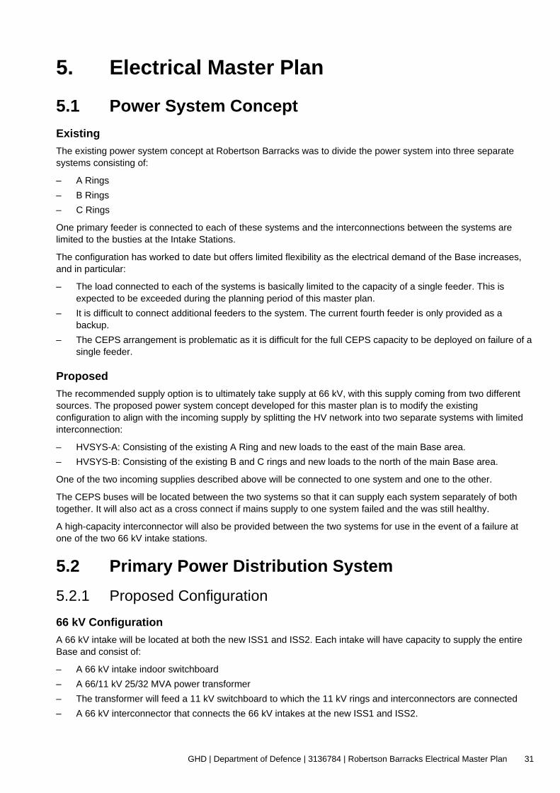
GHD | Department of Defence | 3136784 | Robertson Barracks Electrical Master Plan 31
5. Electrical Master Plan
5.1 Power System Concept
Existing
The existing power system concept at Robertson Barracks was to divide the power system into three separate
systems consisting of:
– A Rings
– B Rings
– C Rings
One primary feeder is connected to each of these systems and the interconnections between the systems are
limited to the busties at the Intake Stations.
The configuration has worked to date but offers limited flexibility as the electrical demand of the Base increases,
and in particular:
– The load connected to each of the systems is basically limited to the capacity of a single feeder. This is
expected to be exceeded during the planning period of this master plan.
– It is difficult to connect additional feeders to the system. The current fourth feeder is only provided as a
backup.
– The CEPS arrangement is problematic as it is difficult for the full CEPS capacity to be deployed on failure of a
single feeder.
Proposed
The recommended supply option is to ultimately take supply at 66 kV, with this supply coming from two different
sources. The proposed power system concept developed for this master plan is to modify the existing
configuration to align with the incoming supply by splitting the HV network into two separate systems with limited
interconnection:
– HVSYS-A: Consisting of the existing A Ring and new loads to the east of the main Base area.
– HVSYS-B: Consisting of the existing B and C rings and new loads to the north of the main Base area.
One of the two incoming supplies described above will be connected to one system and one to the other.
The CEPS buses will be located between the two systems so that it can supply each system separately of both
together. It will also act as a cross connect if mains supply to one system failed and the was still healthy.
A high-capacity interconnector will also be provided between the two systems for use in the event of a failure at
one of the two 66 kV intake stations.
5.2 Primary Power Distribution System
5.2.1 Proposed Configuration
66 kV Configuration
A 66 kV intake will be located at both the new ISS1 and ISS2. Each intake will have capacity to supply the entire
Base and consist of:
– A 66 kV intake indoor switchboard
– A 66/11 kV 25/32 MVA power transformer
– The transformer will feed a 11 kV switchboard to which the 11 kV rings and interconnectors are connected
– A 66 kV interconnector that connects the 66 kV intakes at the new ISS1 and ISS2.

GHD | Department of Defence | 3136784 | Robertson Barracks Electrical Master Plan 32
This arrangement provides good redundancy as it allows supply to be taken from either of the 66 kV incoming
feeders or to be split across them.
11 kV Configuration
The Primary distribution system consists of a number of new primary distribution nodes. Space and other
limitations at the existing nodes (ISS1, ISS2 and ISS3) mean that these cannot be reused and so the new nodes
will be built adjacent to the existing and the existing nodes will be decommissioned.
The new nodes are as follows:
– Two new Intake Switching Stations (ISS):
• ISS1 – located adjacent to the existing ISS2.
This is where the incoming supply to HVSYS-A is connected
• ISS2 – located adjacent to the existing ISS3.
This is where the incoming supply to HVSYS-B is connected.
– HVSYS-A consists of ISS1 and two additional new Primary Switching Stations (PSS):
• PSS1 – located adjacent to the existing ISS1 at CEPS
• PSS4 – The new intake station located within the RCTA development and is currently being installed as
part of that project.
• ISS1, PSS1 and PSS2 are connected together by three Interconnectors in a triangular arrangement.
– HVSYS-B consists of ISS2 and two additional new Primary Switching Stations (PSS):
• PSS2 – located adjacent to the existing ISS1 at CEPS
• PSS3 – located adjacent to the existing ISS2.
• PSS5 – A new switching station located north of Campbell Road to supply the future loads in that area.
• ISS2, PSS2 and PSS3 are connected together by three Interconnectors in a triangular arrangement.
• PSS5 will be supplied by an interconnector from ISS2
– CEPS (existing consisting of two separate switchboards, CEPS1 and CEPS2). These are connected between
PSS1 and PSS2. This allows the CEPS to be connected to either, or both, HVSYS A and HVSYS B. It also
allows HVSYS A and B to be connected together if required.
– A high-capacity 11 kV interconnector will run between the adjacent nodes ISS1 and PSS3.
Primary Distribution Node Construction
The existing 11 kV switchgear at Robertson Barracks is a Schneider SM6. The switchgear that has been installed
is fixed and non-withdrawable.
Given the size and importance of Robertson Barracks, greater flexibility and safety is required with the switchgear.
The new 11 kV switchgear at the primary distribution nodes should be withdrawable, possibly matching that
installed at RAAF Darwin and RAAF Tindal. Withdrawable switchgear would offer the following advantages:
- A faulty switch can quickly be removed and replaced with a spare, getting it back into service with minimal
disruption
- It would increase safety as it offers a visible break when isolating equipment
The new primary distribution nodes will consist of new switchboards in new buildings. This is necessary as, even
though the existing primary distribution nodes (existing ISS1, ISS2 and ISS3) were only commissioned in 2013,
they are deficient:
– The switchrooms are only just big enough for the existing switchboards and so the switchboards cannot be
extended,
– There are numerous non-conformances with the MIEE that existed at the time of construction:
• The switchboards have no remote control from an adjacent room. This means that the operator must
operate the switchgear from directly in front.
• The switchgear is not withdrawable.

GHD | Department of Defence | 3136784 | Robertson Barracks Electrical Master Plan 33
• There is no separate control room or battery room.
Constructing a new facility adjacent will also facilitate changeover to the new system. The new facility can be
constructed and then the cables progressively cut over, thus minimising disruption.
Each new primary distribution node building will consist of three fire-segregated functional spaces:
– 11 kV Switchroom, or Switchrooms in the case of the new ISS
– Control Room to house ancillary equipment, such as comms racks, control panels, DC supplies and LV
switchboards
– Battery room, to house the building DC batteries.
The building will be of masonry construction in accordance with the MIEE.
Interconnectors
The interconnectors allow bulk power transfers between the primary distribution nodes, under all conditions, even
if one of the interconnectors is out of service. To achieve this, and to be consistent with recently installed
infrastructure, the interconnectors shall be sized with a capacity, which is at least equal to the Ultimate Design
Load (UDL) of the HVSYS. This is taken as half of the UDL for the entire Base given in Section 3.6, which is
12 MVA or 630 A.
Current interconnectors are 2x1C 400 mm2 Al per phase. Although the exact configuration is not known, the
current carrying capacity is assessed to be approximately 840 A. This is adequate to meet the above, and
Interconnectors with a 1000 A capacity are recommended going forward.
Each new interconnector would be rated at approximately 1000 A, consisting of 2 x 400 mm2 Cu/XLPE cables per
phase installed underground in conduits. These can be installed as a single cable per phase initially and spare
conduits provided to allow upgrade as load increases.
5.3 Secondary Power Distribution System (Rings)
5.3.1 Number of Rings
The Base currently has eight 11 kV rings. The current RCTA (Range) project will add two more, bringing the total
to ten. Six of these will form HVSYS A and four will form HVSYS B.
It is envisaged that as the Base grows additional rings will be required. The location of these will be decided on a
case-by-case basis depending upon the final location of facilities. This will be a result of:
– Additional load exceeding the capacity of existing rings
– Development occurring in areas not currently served by the electrical distribution system.
5.3.2 Replacement of Ringmains Cables In its HV assessment report Section 6.4.1, Aurecon notes that:
The majority of the Ring Main cables are original installations from early 1990’s of initial construction of Robertson
Barracks. The BEAP report noted that some segments of the Ring Main cable that have been fully replaced with 3
x 1C 120mm^2 Cu/XLPE/NJ/HDPE, and other existing segments have been joined to existing 3 x 1C 120mm^2
Cu/XLPE cables. The derated capacity of the Ring Main cables is 5.12 MVA.
The condition and capacity of the existing ringmains cables is therefore of concern as the majority of HV cables
are 30+ years old and by the 2035 planning horizon will have exceeded the design service life.
Consideration needs to be given to instituting a rolling program to replace existing ringmains cabling in excess of
30 years old or if it experiences high failure rates.
In accordance with Section 5.3.1 above all future ringmains cables shall be 150 mm2 Copper conductor or the
aluminium equivalent.
GHD | Department of Defence | 3136784 | Robertson Barracks Electrical Master Plan 34
5.4 Incoming supply – Solar With the proposed HV primary network configuration, the PV incoming supply to the base shall therefore be:
– PV systems “A” (PVA) and “S” (PVS) - terminating onto the new ISS1 switchboard
– PV systems “B” (PVB) and “C” (PVC) - terminating onto the new ISS2 switchboard
5.5 Emergency Power Generation
5.5.1 CEPS Capacity
The purpose of the CEPS is principally to provide a backup to the Local Emergency Generators (LEGs) that are
the main standby power source for critical and essential facilities. These facilities are usually those with a
Contribution Factor of CF1 and CF2, or those with a post-disaster functionality.
The current CEPS capacity is 6.6 MW, consisting of three 2.2 MW generating sets. Considering the 300 kW
spinning reserve, the available capacity is 6.3 MW (6.7 MVA at 0.94 pf). This capacity corresponds to 31% of the
2035 Ultimate Base Load.
The minimum required CEPS capacity is that which is required to power all facilities that house critical and
essential loads. In the absence of a full Standby Power Report the MIEE provides guidance that in most
circumstances the capacity of the CEPS at establishments like RAAF Bases needs to be at least 70% of the Peak
Demand. Given that Robertson Barracks has a significant amount of LIA, which is a low priority load, 60% of the
Peak Demand is probably a more reasonable percentage.
For an Ultimate Base load of 20.3 MVA at 2035, the CEPS needs to have an available capacity of 11.4 MW
(12.1 MVA @ 0.94 pf). This is an increased capacity of 4.8 MW, which can be achieved by installing two additional
2.5 MW generating sets, totalling is an installed capacity of 11.6 MW.
5.5.2 Proposed CEPS Configuration
It is proposed to augment the existing CEPS to allow for the Base load increase. By 2028 one additional
generating set is required to bring the overall CEPS capacity to 9.1 MW to supply approximately 50% of the Base
until 2032. By 2035 a second set is required to bring the overall CEPS capacity to 11.6 MW.
The additional generating sets will require an extension to the existing CEPS. Due to limitations with the existing
building this will be in the form of a separate building immediately behind the existing CEPS and consist of:
– A single generating hall with space for three generating sets
– A control room
– Ancillary rooms, such as a workshop and storage facility
The existing control room is space constrained and so the control panels will be located in the new CEPS Control
Room.
Additional bulk fuel storage will be provided adjacent to the new building, and probably consist of above-ground
self-bunded tanks.
5.5.3 New CEPS Generator Control System (GCS)
A new generator control system (GCS) will perform automatic starting, capacity scheduling, and send load
shedding signals to the PCMS (described in section 5.6). A new touchscreen MIMIC panel and a redundant
SCADA server arrangement for the PCMS (including a PC usable as a client) will be fitted.
GHD | Department of Defence | 3136784 | Robertson Barracks Electrical Master Plan 35
5.6 Power Control and Monitoring System Monitoring of the HV network is currently provided through the site PCMS. Given the size of the Base HV network,
a comprehensive PCMS is required to monitor the HV network, including status, load flows and faults, and carry
out load shedding within the network.
The data logging and monitoring of the HV network (HV CB) as well as distribution substation LV incomer shall be
implemented.
To allow reliable storage of data the system will be equipped with a large RAID storage. The entire system will be
powered from a dedicated UPS or an inverter fed from the CEPS or the control batteries (either from the new or
existing control room).
5.6.1 Monitoring Functions
The PCMS would have the following monitoring functions:
ISSs, PSSs and CEPS Switchboards
– Power flows on each incoming and outgoing circuit
– Open/closed/tripped status of each circuit
– Primary System faults, such as switchboard fault indications, e.g., trip circuit supervision
– DC system parameters and status
– Other Secondary System parameters and status
– Ventilation and air conditioning faults
– RTU and communications faults
CEPS Plant
– Generating set parameters and status
– Power station ancillary system parameters and status
– DC systems parameters and status
– RTU and communications faults
Distribution Substations
– Open/closed/tripped status of RMU
– Power flows at substation LV switchboard, both incoming and outgoing
– Fault indications e.g., surge diverters
– Transformer faults, such as over temperature
– RTU and communications faults
Process Alarms
– Various alarms and status indication if required, e.g., local emergency generators.
5.6.2 LV Load Shedding
The PCMS would control LV load shedding devices. Loads would be prioritised into groups (‘load groups’), and in
the event of CEPS operation, these groups sequentially restore power (highest priority first), according to the
power available.
The normal arrangement is that the load shedding devices be located within the LV switchboard of the distribution
substations. New and replaced substations in future projects should include these load shedding devices within
the substation LV switchboard.

GHD | Department of Defence | 3136784 | Robertson Barracks Electrical Master Plan 36
To include load shedding at the existing substations that do not include load shedding facilities will require the
replacement of the LV switchboard. In some of the older kiosk substations a complete replacement of the
substation might be required.
5.6.3 Local Emergency Generators (LEGs)
Whenever the CEPS is running in response to a mains failure it issues a command to the various LEGs to keep
running even if they see the mains return. This prevents them from shutting down when the CEPS is powering the
HV network, throwing extra load onto the CEPS.
In these circumstances the CEPS Generator Control System (GCS) normally issues a Run-On command to the
PCMS which then uses a local RTU at the LEG location to keep the LEG running.
The PCMS also receives status indication from the LEG, which it records.
5.7 Preliminary trade pricing estimate GHD has prepared the preliminary trade pricing estimate using information reasonably available to GHD and
based on previous project of similar nature.
The preliminary trade pricing estimate has been prepared for the purpose of providing Department of Defence with
an order of magnitude trade pricing required to implement this Electrical Master Plan and must not be used for any
other purpose.
The trade pricing estimate is a preliminary estimate only. No detailed quotation has been obtained for actions
identified in this report. GHD does not represent, warrant or guarantee that the works can or will be undertaken at
a cost which is the same or less than the preliminary trade pricing estimate
Note: The works related to PWC (including incoming supply feeders, PWC network upgrade, etc.) are not part of
these preliminary pricing estimates.

GHD | Department of Defence | 3136784 | Robertson Barracks Electrical Master Plan 37
Table 3 Preliminary trade pricing estimate
Item Order of magnitude estimate
Qty Total
NIS1 and NIS2 66/11 kV indoor substation, including:
– 66/11 kV 32 MVA transformer (indoor)
– 66 kV indoor Gas Insulated Switchgear (GIS)
– 11 kV indoor switchgear
– Building
– NIS – ISS 11 kV incomers
$18M – $25M each 2 $36M – $50M
ISS1 (including PSS3), ISS2, PSS1, PSS2, PSS4
indoor switching station, including:
– 11 kV indoor Gas Insulated Switchgear (GIS)
– Building
$2.5M – $3.5M each 5 $12.5M - $17.5M
NIS1 – NIS2 66 kV interconnector (approx. 3.5 km) $4.5M – $5.5M 1 $4.5M – $5.5M
11 kV Interconnectors:
– PSS4 – ISS1 (approx. 1 km)
– PSS4 – PSS1 (approx. 1.2 km)
– ISS2-PSS1 interconnector 1 (approx. 2.5 km)
– ISS2-PSS1 interconnector 2 (approx. 2.5 km)
$1M – $2M
$1M – $2M
$2.5M – $4.5M
$2.5M – $4.5M
CEPS, including
– New building
– 2 new 11 kV generating sets
$15M – $20M

GHD | Department of Defence | 3136784 | Robertson Barracks Electrical Master Plan 38
6. References
6.1 Referenced Documents
[1]. AURECON, ‘04618 – National Electrical Master Plan Consultancy - 1200 Robertson Barracks NT
HV Systems Report – DEWPO’ - 27/08/2020
[2]. PowerWater, ‘Transmission and Distribution Annual Planning Report 2019’
[3]. PowerWater, ‘Transmission and Distribution Annual Planning Report 2020’
[4]. AECOM, ‘Base Engineering Assessment Program – Robertson Barracks, Rev 3’ - 04/11/2013.
[5]. PowerWater – ‘Power networks – Underground Approved Material List’ – November 2028
[6]. Department of Defence, ‘Manual of Engineering Infrastructure – Electrical’, 2011.
[7]. General Cable manufacturer
6.2 Abbreviations
Al Aluminium
ARZSS Archer Zone Substation
BEAP Base Engineering Assessment Program
BEZSS Berrimah Zone Substation
CB Circuit Breaker
CEPS Central Emergency Power Station
CIPS Channel Island Power Station
Cu Copper
DC Direct Current
DNSP Distribution Network Service Provider, in this case PWC
EDP Electrical Development Plan
EMP Electrical Master Plan
GCS Generator Control System
HCTS Hudson Creek Terminal Substation
HV High Voltage
ISS Intake Sub-Station
LV Low Voltage
MIEE Manual of Infrastructure Engineering Electrical
PDS Project Delivery Services
PCMS Power Control and Monitoring System
PVC Polyvinyl Chloride
PWC Power and Water Corporation
PAZSS Palmerston Zone Substation

GHD | Department of Defence | 3136784 | Robertson Barracks Electrical Master Plan 39
RMU Ring Main Unit
RTU Remote Terminal Unit
SCADA Supervisory Control and Data Acquisition
UBL Ultimate Base Load
UDL Ultimate Design Load
WPS Waddell Power Station
XPLE Cross-linked Polyethylene
ZSS Zone Substation

GHD | Department of Defence | 3136784 | Robertson Barracks Electrical Master Plan 40
Appendices

GHD | Department of Defence | 3136784 | Robertson Barracks Electrical Master Plan 41
Appendix A Drawings

G GG
ISS1A ISS1B
PWCINCOMER "D"
RING
A4
RING
A1
RING
A2
RING
A4
ISS2A
ISS2
-ISS1
INTE
RCON
NECT
OR
PWCINCOMER "A"
PWCINCOMER "B"
PV "A"
ISS2B
RING C1
RING C2
RING B1
RING B2
ISS1-ISS3 INTERCONNECTOR
ISS2-ISS3 INTERCONNECTOR
PWC INCOMER "C"
PV "C"
PV "B"
ISS3
BIS
S3A
Conditions of Use. This document may only be used by GHD's client (and any otherperson who GHD has agreed can use this document) for the purpose for which it wasprepared and must not be used by any other person or for any other purpose.
Plot Date: File Name:4 May 2021 - 1:43 PM G:\Network Trash\Jovel\3136784\31-36784-16-E001.dwg
Plotted by:
Jovel San Juan
Project No.
www.ghd.com
Drawing No.
DrawingTitle
Client
Project
Status
Rev Description Checked Approved Date
Author Drafting Check
Designer Design CheckStatusCode
Size
Rev
A1DEPARTMENT OF DEFENCE
DEFENCE RENEWABLEENERGY PROGRAMPRELIMINARY
ROBERTSON BARRACKSELECTRICAL MASTER PLANEXISTING HV NETWORKSINGLE LINE DIAGRAM
3136784-16 31-36784-16-E001 AJ. SAN JUAN
E. GOASDOUE
-
-
A ISSUED FOR REVIEW EJG - -
-
Level 9, 180 Lonsdale Street,
Melbourne VIC 3000 Australia
T 61 3 8687 8000 F 61 3 8687 8111
E [email protected] W www.ghd.com

G
CEPS
G G GGSPARE
NEW PSS1 NEW PSS2
PSS4-PSS1 INTERCONNECTOR
PSS4-ISS1 INTERCONNECTOR
OLD FEEDER FROM IS1DIVERTED TO PSS4
ISS1
-PSS
1 INT
ERCO
NNEC
TOR
RING
A1
RING
A2
RING
A3
RING
A4
(NOTE 2)
PSS1 PSS2
(NOTE 3)
PSS4
ISS1 PSS3
PSS3
-PSS
2 INT
ERCO
NNEC
TOR
HV RING
HV INTERCONNECTOR
LEGEND:
NOTES:1. NEW ISS2 LOCATED AT EXISTING ISS3 SITE.2. NEW ISS1 AND PSS3 LOCATED AT EXISTING ISS2 SITE.3. EXISTING RTCA ISS TO BE RENAMED PSS4.4. SWITCHGEAR TO HAVE WITHDRAWABLE BREAKERS.
GSPARE
11kV INCOMING SUPPLY FROMPALMERSTON ZONE SUBSTATION
ISS2-PSS3 INTERCONNECTOR
RING B2
RING B1
RING C2
RING C1
ISS2-PSS2 INTERCONNECTOR
(NOTE 1)
ISS2
11kV
INCO
MING
SUP
PLY
FROM
BERR
IMAH
ZON
E SU
BSTA
TION
PSS5
ISS2-PSS5 INTERCONNECTOR 1
ISS2-PSS5 INTERCONNECTOR 2
HVSY
S B
HVSY
S A
PV "A"
PV "B
"PV
"C"
Conditions of Use. This document may only be used by GHD's client (and any otherperson who GHD has agreed can use this document) for the purpose for which it wasprepared and must not be used by any other person or for any other purpose.
Plot Date: File Name:9 June 2021 - 11:11 AM G:\Network Trash\Jovel\3136784\31-36784-16-E002.dwg
Plotted by:
Jovel San Juan
Project No.
www.ghd.com
Drawing No.
DrawingTitle
Client
Project
Status
Rev Description Checked Approved Date
Author Drafting Check
Designer Design CheckStatusCode
Size
Rev
A1DEPARTMENT OF DEFENCE
DEFENCE RENEWABLEENERGY PROGRAMPRELIMINARY
ROBERTSON BARRACKSELECTRICAL MASTER PLANPROPOSED HV NETWORKSINGLE LINE DIAGRAM - OPTION 1
3136784-16 31-36784-16-E002 AJ. SAN JUAN
E. GOASDOUE
-
-
A ISSUED FOR REVIEW EJG - -
-
Level 9, 180 Lonsdale Street,
Melbourne VIC 3000 Australia
T 61 3 8687 8000 F 61 3 8687 8111
E [email protected] W www.ghd.com

G
CEPS
G G GGSPARE
NEW PSS1 NEW PSS2
PSS4-PSS1 INTERCONNECTOR
PSS4-ISS1 INTERCONNECTOR
OLD FEEDER FROM IS1DIVERTED TO PSS4
ISS1
-PSS
1 INT
ERCO
NNEC
TOR
RING
A1
RING
A2
RING
A3
RING
A4
(NOTE 2)
PSS1 PSS2
(NOTE 3)
PSS4
ISS1 PSS3
PSS3
-PSS
2 INT
ERCO
NNEC
TOR
HV RING
HV INTERCONNECTOR
LEGEND:
NOTES:1. NEW ISS2 LOCATED AT EXISTING ISS3 SITE.2. NEW ISS1 AND PSS3 LOCATED AT EXISTING ISS2 SITE.3. EXISTING RTCA ISS TO BE RENAMED PSS4.4. SWITCHGEAR TO HAVE WITHDRAWABLE BREAKERS.
GSPARE
ISS2-PSS3 INTERCONNECTOR
RING B2
RING B1
RING C2
RING C1
ISS2-PSS2 INTERCONNECTOR
(NOTE 1)
ISS2
PSS5
ISS2-PSS5INTERCONNECTOR 1
ISS2-PSS5INTERCONNECTOR 2
HVSY
S B
HVSY
S A
NIS166/11kV
25/32 MVA
66kV FROMPALMERSTONZONE SUBSTATION
PV "A" NIS266/11kV
25/32 MVA
66kV FROM BERRIMAHZONE SUBSTATION
PV "C
"PV
"B"
Conditions of Use. This document may only be used by GHD's client (and any otherperson who GHD has agreed can use this document) for the purpose for which it wasprepared and must not be used by any other person or for any other purpose.
Plot Date: File Name:9 June 2021 - 11:13 AM G:\Network Trash\Jovel\3136784\31-36784-16-E003.dwg
Plotted by:
Jovel San Juan
Project No.
www.ghd.com
Drawing No.
DrawingTitle
Client
Project
Status
Rev Description Checked Approved Date
Author Drafting Check
Designer Design CheckStatusCode
Size
Rev
A1DEPARTMENT OF DEFENCE
DEFENCE RENEWABLEENERGY PROGRAMPRELIMINARY
ROBERTSON BARRACKSELECTRICAL MASTER PLANPROPOSED HV NETWORKSINGLE LINE DIAGRAM - OPTION 2
3136784-16 31-36784-16-E003 AJ. SAN JUAN
E. GOASDOUE
-
-
A ISSUED FOR REVIEW EJG - -
-
Level 9, 180 Lonsdale Street,
Melbourne VIC 3000 Australia
T 61 3 8687 8000 F 61 3 8687 8111
E [email protected] W www.ghd.com

G
CEPS
G G GGSPARE
NEW PSS1 NEW PSS2
PSS4-PSS1 INTERCONNECTOR
PSS4-ISS1 INTERCONNECTOR
OLD FEEDER FROM IS1DIVERTED TO PSS4
ISS1
-PSS
1 INT
ERCO
NNEC
TOR
RING
A1
RING
A2
RING
A3
RING
A4
(NOTE 2)
PSS1 PSS2
(NOTE 3)
PSS4
ISS1 PSS3
PSS3
-PSS
2 INT
ERCO
NNEC
TOR
HV RING
HV INTERCONNECTOR
LEGEND:
NOTES:1. NEW ISS2 LOCATED AT EXISTING ISS3 SITE.2. NEW ISS1 AND PSS3 LOCATED AT EXISTING ISS2 SITE.3. EXISTING RTCA ISS TO BE RENAMED PSS4.4. SWITCHGEAR TO HAVE WITHDRAWABLE BREAKERS.
GSPARE
11kV INCOMING SUPPLY FROMNEW ROBERTSON BARRACKS ZONE SUBSTATION
ISS2-PSS3 INTERCONNECTOR
RING B2
RING B1
RING C2
RING C1
ISS2-PSS2 INTERCONNECTOR
(NOTE 1)
ISS2
11kV
INCO
MING
SUP
PLY
FROM
NEW
ROB
ERTS
ON B
ARRA
CKS
ZONE
SUB
STAT
ION
PSS5
ISS2-PSS5 INTERCONNECTOR 1
ISS2-PSS5 INTERCONNECTOR 2
HVSY
S B
HVSY
S A
IS1
PV "A"
PV "B
"PV
"C"
Conditions of Use. This document may only be used by GHD's client (and any otherperson who GHD has agreed can use this document) for the purpose for which it wasprepared and must not be used by any other person or for any other purpose.
Plot Date: File Name:9 June 2021 - 11:11 AM G:\Network Trash\Jovel\3136784\31-36784-16-E004.dwg
Plotted by:
Jovel San Juan
Project No.
www.ghd.com
Drawing No.
DrawingTitle
Client
Project
Status
Rev Description Checked Approved Date
Author Drafting Check
Designer Design CheckStatusCode
Size
Rev
A1DEPARTMENT OF DEFENCE
DEFENCE RENEWABLEENERGY PROGRAMPRELIMINARY
ROBERTSON BARRACKSELECTRICAL MASTER PLANPROPOSED HV NETWORKSINGLE LINE DIAGRAM - OPTION 3
3136784-16 31-36784-16-E004 AJ. SAN JUAN
E. GOASDOUE
-
-
A ISSUED FOR REVIEW EJG - -
-
Level 9, 180 Lonsdale Street,
Melbourne VIC 3000 Australia
T 61 3 8687 8000 F 61 3 8687 8111
E [email protected] W www.ghd.com

GHD | Department of Defence | 3136784 | Robertson Barracks Electrical Master Plan 42
ghd.com The Power of Commitment