313 Lab03 Thin Lenses - University of Delaware
8
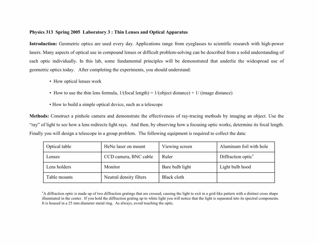
Physics 313 Spring 2005 Laboratory 3 : Thin Lenses and Optical Apparatus Introduction: Geometric optics are used every day. Applications range from eyeglasses to scientific research with high-power lasers. Many aspects of optical use in compound lenses or difficult problem-solving can be described from a solid understanding of each optic individually. In this lab, some fundamental principles will be demonstrated that underlie the widespread use of geometric optics today. After completing the experiments, you should understand: • How optical lenses work • How to use the thin lens formula, 1/(focal length) = 1/(object distance) + 1/ (image distance) • How to build a simple optical device, such as a telescope Methods: Construct a pinhole camera and demonstrate the effectiveness of ray-tracing methods by imaging an object. Use the “ray” of light to see how a lens redirects light rays. And then, by observing how a focusing optic works, determine its focal length. Finally you will design a telescope in a group problem. The following equipment is required to collect the data: Black cloth Neutral density filters Table mounts Light bulb hood Bare bulb light Monitor Lens holders Diffraction optic * Ruler CCD camera, BNC cable Lenses Aluminum foil with hole Viewing screen HeNe laser on mount Optical table * A diffraction optic is made up of two diffraction gratings that are crossed, causing the light to exit in a grid-like pattern with a distinct cross shape illuminated in the center. If you hold the diffraction grating up to white light you will notice that the light is separated into its spectral components. It is housed in a 25 mm diameter metal ring. As always, avoid touching the optic.
Transcript of 313 Lab03 Thin Lenses - University of Delaware
Physics 313 Spring 2005 Laboratory 3 : Thin Lenses and Optical Apparatus
Introduction: Geometric optics are used every day. Applications range from eyeglasses to scientific research with high-power
lasers. Many aspects of optical use in compound lenses or difficult problem-solving can be described from a solid understanding of
each optic individually. In this lab, some fundamental principles will be demonstrated that underlie the widespread use of
geometric optics today. After completing the experiments, you should understand:
• How optical lenses work
• How to use the thin lens formula, 1/(focal length) = 1/(object distance) + 1/ (image distance)
• How to build a simple optical device, such as a telescope
Methods: Construct a pinhole camera and demonstrate the effectiveness of ray-tracing methods by imaging an object. Use the
“ray” of light to see how a lens redirects light rays. And then, by observing how a focusing optic works, determine its focal length.
Finally you will design a telescope in a group problem. The following equipment is required to collect the data:
Black clothNeutral density filtersTable mounts
Light bulb hoodBare bulb lightMonitorLens holders
Diffraction optic*RulerCCD camera, BNC cableLenses
Aluminum foil with holeViewing screenHeNe laser on mountOptical table
*A diffraction optic is made up of two diffraction gratings that are crossed, causing the light to exit in a grid-like pattern with a distinct cross shapeilluminated in the center. If you hold the diffraction grating up to white light you will notice that the light is separated into its spectral components.It is housed in a 25 mm diameter metal ring. As always, avoid touching the optic.

Experiment 1: Pinhole Camera
A pinhole camera is a simple device that works on the principle that
light is a ray. The basic setup is shown in Fig. 1. A small hole is used
to select light rays from an object screen, O. After the pinhole, P, the
light rays from the object form an image of the original object. Use
ray tracing to understand this phenomena. Because the pinhole blocks
out most of the light rays, it is difficult to see small details of the
formed image due to such a small amount of light being transmitted
through the hole. A CCD camera is more sensitive than your eye and
may be used to remotely observe weak light signals (Fig. 1, M).
Mount a light bulb with paper taped to the front of the hood to diffuse
the light, the screen with the pinhole, and the CCD camera on an
optical table and ensure they are aligned, level and centered. A piece
of aluminum foil and a needle can be used to make the pinhole (make
it as small as possible). Mount the target object between the light
bulb and pinhole. Note that this object’s image is also in focus. Use
black fabric to create a shield around the CCD camera to block out
excess light. Adjust the target’s distance from the light source in
order to see the whole image.
Figure 1: Pinhole camera setup consisting of: O-object screen, L-light source with hood and diffuser, P-pinhole, CCD - camera, M – monitor of CCD output. Also shown in the figure is the computer (I) with two previously grabbed images.
Figure 2: Demonstrating the pinhole camera’s depth of field. The hand is nearer to the camera than the computer, hence is bigger. However, both are in focus.

When you have an image, then capture it using the program Videopoint
Capture to capture a movie (there is no single frame capture option). Save
a frame of the movie - it can be opened for analysis and printing later with
Videopoint 2.5.
Once you have a frame you are happy with, increase and decrease the size
of the pin hole and repeat the picture taking procedure.
Record your observations and ray-tracing diagrams of light rays of your
pinhole setup in your lab book. Consider the following in your
observations:
• Why is the image brightest right next to the pinhole?
• Why is the image always in focus?
• What changes did you observe once the pinhole size was
changed?

Experiment 2: Image/Object Distance Relationship
In this experiment, you’ll determine the focal length of a lens by studying the
relationship between an object and its image. An example of the setup is shown in Fig.
3 with a light bulb as an object. Look on the other side of the lens for the image.
Adjust the screen distance until the image is clearly in focus (see Fig. 4).
Record the object, o, and image, i, distances from the lens; repeat for several object
distances. In your lab notebook, sketch the layout of the optics with the “light rays”.
Use the imaging relationship for a thin lens (1/f=1/o+1/i) and a plot of your observed
values to determine the focal length of the lens. Since you know the thin lens formula,
decide what form of the measurements should be used in your plot, e.g. 1/o, 1/i, i/o,
etc. Make note of the fit correlation, i.e. the accuracy of the fit to the data. Using
ordered data set pairs (o, i), calculate the focal length and compare the average value
to the one determined from the graph. Calculate the standard deviation from the
ordered pair data. Do the two different analyses agree or disagree? Why?
Figure 3: Experiment arrangement: o=object distance,i=image distance
o i
30 - 50 cm
Figure 4: Focusing the image: move the screen untila clear image appears

Next, determine the focal length of a negative lens. Keep in mind that a negative lens
is a diverging lens. Evaluate the relationship between the object and image for a
negative lens, then propose a method for determining the focal length. Sketch the optic
layout and the optical rays in your notebook.
Try your experiment. Record your procedure, measurements, and calculation of the
negative focal length, f, in your lab notebook. How does a lens work differently than a
pinhole when it forms an image?
Experiment 3: Applications of Lenses – Magnification
Lenses can be used to produce magnified or “de”-magnified images of an object.
Illuminate the transmission test target (Fig.5, T) with diffused light. Diffused light can
be created by taping white paper over the light bulb cone (Fig.5, C & W). Using your
focusing lens, try several object, o, and image, i, distances as before, but note
quantitatively how the image size, is, changes relative to the object size, os, as a
function of o and i. Record the parameters (o, i, os, is) for a half dozen positions.
Inspect the ratios of i/o and is/os and speculate on a mathematical relationship for the
magnification of a lens, M ≡ is/os, as a function of i and o.
Figure 5: Measuring image size, is:C-cone, T-transmissiontest target(object), W-white paper taped to cone, o=objectdistance, i=image distance
CT
o i
W

Figure 6: Telescope. O- collimated light from an object at infinity, M- final magnified image, Lb- objected lens, Lc- ocular lens, i- image, E- eye, fb- focal length of the objective lens, fc- focal length of the ocular lens.
Experiment 4. Telescope
A telescope is an optical instrument whose function is to magnify
and collect light from distant objects. A simple telescope for
ocular (eye) observation is made up of at least two lenses, an
objective and an ocular lens. The objective lens gathers
collimated, or parallel, rays of light from a distant object and
focuses it. The ocular lens then takes that focused light and re-
collimates the condensed light to a size comparable to the size of
our pupil (5-7mm).
The ocular lens also magnifies the image. The angular
magnification of the telescope equals the ratio of the focal lengths.
Before constructing your telescope, a collimated light source is
required to act as a distant object. A collimated beam consists of
approximately-parallel rays that do not focus for several meters.
Set up a diffraction optic and a lens separated by a distance equal
to the lens’ focal length, f. Shine a HeNe beam through the
diffraction optic and confirm that the beam is collimated by
observing the image on the viewing screen; if not, adjust the lens
distance until the beam is collimated (see Fig. 7).
D C
f
Figure 7: Collimating the HeNe light: D-diffraction optic;C-positive lens placed a focal length from D; move the screen to ensure that beam-size remains constant

Construct a telescope with a magnification of approximately 4. Place a viewing
screen behind the ocular lens as shown in figure 8. The longer focal length lens
should be first, i.e. closer to the ray source. The output rays should also be
collimated; if not, small adjustments to the lens separation may be required.
Determine the size of the cross of rays exiting the collimating lens to the cross on
the viewing screen.
How does the size of the cross compare to the magnification of the telescope?
Remove the laser, diffraction optic, and collimating lens, then look at a distant
object through the telescope in the same direction as the rays (i.e. put your eye
where the diffraction optic was). Record your observations. Now look from the
other side. Does the magnification appear to be the reciprocal of the
concentration of the light rays from before? This is a paradox. When the
distance between the light rays is spreading out through the telescope, the
telescope demagnifies, but when the light rays are made closer together and
condensed the telescope magnifies. The resolution of the paradox comes when
considering the angular magnification. Use ray tracing to show how
magnification actually occurs (figure 6 may help). Figure 8: Telescope
Telescope
D C
f
Figure 7: Collimating the HeNe light: D-diffraction optic;C-positive lens placed a focal length from D; move the screen to ensure that beam-size remains constant

Group problem: The Narcissistic Neighbor
You have always prided yourself on your top of the line hair care products, and openly brag that no one can beat your shine.
However, last night as you were entering your building you noticed the person who lives in the apartment directly across
the street from yours going out for a night on the town. Not only was their “shine” better than you have ever been able to
achieve, but their remarkable aroma was noticeable from your doorway. You make it your mission to uncover what
magical elixir has been used. Lucky for you, your neighbor has left his bathroom blinds open and you have a clear view
of the bathroom shelf. The distance between the windows is about 50 meters and the lettering of the bottle is probably
about 4 centimeters tall, far too small to see with the naked eye from your apartment although easy to read from a normal
distance of 30 cm.
a. What is the angular size of the object when it is readable with the naked eye?
b. What is the angular size of the object from your apartment?
c. What magnification is needed to make out the text?
d. Construct a telescope with the necessary magnification and test it with text placed 50 m away. (A sign will be placed 50
m away from the lab, do not physically approach the sign – use your telescope to read the text.)
e. What does the text say your neighbor has that you don’t?