31.2 CONTRACTS - Transport
51
31.2 CONTRACTS TRAFFIC SIGNALS SARTSM – VOL 3 MAY 2012 9 Very often, a Dayworks Schedule is also included to allow for abnormal circumstances not necessarily forming part of the contract but where it is convenient to have these additional activities undertaken by the contractor. The Dayworks Schedule is, however, not considered as part of the contract for adjudication purposes. 10 Because of the issue of Variation Orders, it is necessary at completion of the project for “As Built” drawings to be submitted to the client. In the event of any subsequent dispute, reference is made to the “As Built” and not to the original design drawings. 11 Many contracts also provide for a period of maintenance, usually with a duration of twelve months, to ensure that there are no latent defects in the work as delivered. Any defects revealed during this maintenance period are repaired by the contractor at his own expense. 31.4 TENDER PROCESS 1 The client issues a Call for Tenders by advertising it in gazettes as well as newspapers. This advertisement typically includes: (a) The name of the client. (b) The number and name of the project being tendered for. (c) A brief description of its content. (d) The closing date for submission of bids. (e) The source from which tender documents can be obtained, including reference to any payment that must be made for these documents, specifying whether this is a refundable deposit or not. 2 The tender documents are, in fact, the contract documents and include a list of quantities against which the tenderer can quote rates for each item billed. 3 If the client considers a Tenderers’ Site Visit desirable, details of the date and venue will be included in the Call for Tenders. The Site Visit may be compulsory, in which case the client will issue Certificates of Attendance to tenderers. These should then be bound into the submitted bids. Failure to return a certificate could be deemed adequate grounds for rejection of the associated bid. 4 At the Site Visit, the client will describe the full extent of the works and draw attention to any points of particular concern as well as clarifying any uncertainties that would-be tenderers may have. 5 Tender submissions can take many forms. One method that can be followed consists of first requesting the tenderer to submit information illustrating an ability to undertake the intended project. This can be followed by a request for a technical proposal, which in turn may be followed by a request for the final bid. 6 A second method is the two-envelope process in which a tenderer submits a technical proposal (as well as information on the ability of the tenderer to undertake the intended project) in one envelope and a bid in the other envelope. Tenderers are then first adjudicated on the submitted technical proposals, followed by a second round of adjudication based on submitted bids. 7 The two-envelope method has fallen into disfavour because, particularly on large projects, pricing a tender is usually not a trivial task and pricing strategies can, in fact, be quite complex. It is considered inequitable to require a tenderer to devote significant amounts of time and money to deriving a bid when, in the opinion of the client, he or she is not competent to undertake the project. On relatively small and straightforward projects, it does however have the advantage of shortening the time span between advertisement and award of contract. 31.5 PROCUREMENT 1 A somewhat different form of contract involves the procurement of supplies outside the scope of normal design, construction and maintenance contracts. It would be patently ridiculous for an authority to have to call for tenders every time a light bulb had to be replaced. As a public body, the road authority must, however, be able to account for all funds disbursed. 2 In effect, procurement contracts amount to the creation of a panel of preferred suppliers for specified products with prices agreed to for a finite period, usually one year in duration. 3 Apart from the benefit of the creation of a system whereby public accountability is subject to audit, a properly structured procurement contract relieves the client of the necessity for maintaining a large stores department carrying a variety of capital and consumable items. 31.6 SERVICE LEVEL AGREEMENTS 1 Service Level Agreements are another specialised form of contract. They are brought into play when a road authority elects to outsource one or other of the activities that would normally be carried out in- house. A case in point would be the maintenance of all its traffic signalisation equipment. 2 All the normal conditions of the contract previously described apply equally to the Service Level Agreement. What is additionally specified, is the extent and quality of service required. For example, the maximum acceptable time elapsed between a request for service and arrival on site would be defined in the agreement. 31.7 BIBLIOGRAPHY 1 SAICE, 1982, General Conditions of Contract, South African Institution of Civil Engineering, Johannesburg. 2 FIDIC, 1987, Conditions of contract for electrical and mechanical works including erection on site, with Forms of Tender and Agreement, International Federation of Consulting Engineers, Lausanne.
Transcript of 31.2 CONTRACTS - Transport

31.2 CONTRACTS
TRAFFIC SIGNALS SARTSM – VOL 3 MAY 2012
9 Very often, a Dayworks Schedule is also included to allow for abnormal circumstances not necessarily forming part of the contract but where it is convenient to have these additional activities undertaken by the contractor. The Dayworks Schedule is, however, not considered as part of the contract for adjudication purposes.
10 Because of the issue of Variation Orders, it is necessary at completion of the project for “As Built” drawings to be submitted to the client. In the event of any subsequent dispute, reference is made to the “As Built” and not to the original design drawings.
11 Many contracts also provide for a period of maintenance, usually with a duration of twelve months, to ensure that there are no latent defects in the work as delivered. Any defects revealed during this maintenance period are repaired by the contractor at his own expense.
31.4 TENDER PROCESS
1 The client issues a Call for Tenders by advertising it in gazettes as well as newspapers. This advertisement typically includes:
(a) The name of the client.
(b) The number and name of the project being tendered for.
(c) A brief description of its content.
(d) The closing date for submission of bids.
(e) The source from which tender documents can be obtained, including reference to any payment that must be made for these documents, specifying whether this is a refundable deposit or not.
2 The tender documents are, in fact, the contract documents and include a list of quantities against which the tenderer can quote rates for each item billed.
3 If the client considers a Tenderers’ Site Visit desirable, details of the date and venue will be included in the Call for Tenders. The Site Visit may be compulsory, in which case the client will issue Certificates of Attendance to tenderers. These should then be bound into the submitted bids. Failure to return a certificate could be deemed adequate grounds for rejection of the associated bid.
4 At the Site Visit, the client will describe the full extent of the works and draw attention to any points of particular concern as well as clarifying any uncertainties that would-be tenderers may have.
5 Tender submissions can take many forms. One method that can be followed consists of first requesting the tenderer to submit information illustrating an ability to undertake the intended project. This can be followed by a request for a technical proposal, which in turn may be followed by a request for the final bid.
6 A second method is the two-envelope process in which a tenderer submits a technical proposal (as well as information on the ability of the tenderer to undertake the intended project) in one envelope and a bid in the other envelope. Tenderers are then first adjudicated on the submitted technical proposals, followed by a second round of adjudication based on submitted bids.
7 The two-envelope method has fallen into disfavour because, particularly on large projects, pricing a tender is usually not a trivial task and pricing strategies can, in fact, be quite complex. It is considered inequitable to require a tenderer to devote significant amounts of time and money to deriving a bid when, in the opinion of the client, he or she is not competent to undertake the project. On relatively small and straightforward projects, it does however have the advantage of shortening the time span between advertisement and award of contract.
31.5 PROCUREMENT
1 A somewhat different form of contract involves the procurement of supplies outside the scope of normal design, construction and maintenance contracts. It would be patently ridiculous for an authority to have to call for tenders every time a light bulb had to be replaced. As a public body, the road authority must, however, be able to account for all funds disbursed.
2 In effect, procurement contracts amount to the creation of a panel of preferred suppliers for specified products with prices agreed to for a finite period, usually one year in duration.
3 Apart from the benefit of the creation of a system whereby public accountability is subject to audit, a properly structured procurement contract relieves the client of the necessity for maintaining a large stores department carrying a variety of capital and consumable items.
31.6 SERVICE LEVEL AGREEMENTS
1 Service Level Agreements are another specialised form of contract. They are brought into play when a road authority elects to outsource one or other of the activities that would normally be carried out in-house. A case in point would be the maintenance of all its traffic signalisation equipment.
2 All the normal conditions of the contract previously described apply equally to the Service Level Agreement. What is additionally specified, is the extent and quality of service required. For example, the maximum acceptable time elapsed between a request for service and arrival on site would be defined in the agreement.
31.7 BIBLIOGRAPHY
1 SAICE, 1982, General Conditions of Contract, South African Institution of Civil Engineering, Johannesburg.
2 FIDIC, 1987, Conditions of contract for electrical and mechanical works including erection on site, with Forms of Tender and Agreement, International Federation of Consulting Engineers, Lausanne.

ANNUAL REPORTS 32.1
MAY 2012 SARTSM – VOL 3 TRAFFIC SIGNALS
CHAPTER 32: ANNUAL REPORTS
32.1 INTRODUCTION
1 The annual report is an important function of a traffic signal division. The purpose of the annual report is to provide information on the work of the division and to indicate that the work was undertaken responsibly and in the best interest of the community and the road user.
2 Performance management and the assessment of key performance indices are mechanisms to ensure that the goals and objectives of providing traffic signals are achieved. The annual report should provide information on the degree to which these goals and objectives have been reached.
32.2 CONTENTS OF THE ANNUAL REPORT
32.2.1 General
1 The annual report should provide information on aspects such as the following:
(a) Institutional.
(b) Special projects.
(c) Routine projects.
(d) Training and technology transfer.
(e) Programme and budget.
(f) Statistics.
2 Throughout the report there should be an emphasis on achievements and the degree to which key performance indices have been achieved.
32.2.2 Institutional
1 The annual report should contain information on the institutional and organisational structure as well as staff composition of the traffic signal division. Staff shortages and vacancies should also be indicated.
2 The facilities available in the traffic division should also be described, together with an indication of the traffic control system in use.
3 Information should also be given on the utilisation of consulting engineers and contractors, as well as the projects on which they were utilised.
4 Details should also be provided on co-operation with other authorities as well as duties undertaken on behalf of such authorities.
32.2.3 Special projects
1 The annual report should provide short summaries of special projects that have been undertaken by the traffic signal division.
2 Special projects would, for example, include upgrading to a new traffic signal system, installation of an operations control centre, installation of new traffic signals, etc. A special project is one that is not routinely undertaken each year.
32.2.4 Routine projects
1 Routine projects are those routinely undertaken each year. These include the upgrading of traffic signal settings, maintenance activities, etc.
2 A short description should be given in the report of all the routine activities of the signal division.
32.2.5 Training and technology transfer
1 The development of skills and knowledge in the traffic signal division is of such importance that it warrants a special section in the annual report. The signal division should be proud of any efforts made to provide training and to provide opportunities to personnel to improve their knowledge of traffic signalisation.
2 The report should highlight the importance of continued skill development and may refer to this manual to indicate the responsibility of road authorities to institute specific programmes at improving skills and knowledge.
32.2.6 Programme and budget
1 One of the essential elements of the report is the work programme and budget of the traffic signal division, for the current year as well as the future year.
2 Proper account must be given of all work and expenses undertaken by the traffic signal division. Any new proposed projects should be well motivated and their benefits to the community and the road user explained.
32.2.7 Statistics
1 Detailed statistics should be given in the report on all the activities of the traffic signal division. These statistics must cover the work of all personnel as well as consulting engineers and contractors.
2 Statistics should be given on aspects such as the following:
(a) Staff levels, subdivided according to function and qualifications.
(b) Traffic signal installations and other facilities.
(c) New traffic signal installations.
(d) Upgraded traffic signal installations.
(e) Traffic studies and accident statistics.
(f) Maintenance activities.
(g) Reported malfunctions, subdivided into classes of malfunctions.

32.2 ANNUAL REPORTS
TRAFFIC SIGNALS SARTSM – VOL 3 MAY 2012

DIGITISED VERSION – May 2012


GLOSSARY OF TERMS A.1
MAY 2012 SARTSM – VOL 3 TRAFFIC SIGNALS
APPENDIX A: GLOSSARY OF TERMS
A.1 INTRODUCTION
1 This glossary of terms provides the terminology, abbreviations, and expressions used in traffic signal control. It includes terminology from the fields of traffic, electrical and electronic engineering which the practising traffic signal designer may come across from time to time.
2 The term defined is given in bold at the head of each definition. Where necessary, optional alternative terms and abbreviations are also given.
A.2 GLOSSARY OF TERMS
1 actuation – The operation of a detector in
registering the presence or passage of a vehicle or pedestrian.
2 all-red (interval) A condition (part of the cycle)
when red light signals are displayed simultaneously to conflicting movements.
3 amber light signal/interval See yellow light
signal/interval.
4 area traffic control/ATC The co-ordination of a
number of signals in a road network by means of a central controller.
5 aspect A single lamp unit of a traffic signal which
is one of the prescribed colours and which is capable of being internally illuminated. An illuminated aspect is called a light signal.
6 bus light signal A light signal for the control of
minibuses and buses in a reserved bus lane.
7 cabinet An outdoor enclosure for housing the
controller and associated equipment.
8 cableless linking A method of coordinating
signals without use of a cable.
9 call See demand.
10 cantilever A supporting beam (for a signal light)
fixed at one end only to a vertical post, similar to an inverted "L".
11 capacity In terms of traffic, the maximum number
of vehicles that can pass across the stop line of an approach road to a signal, or a traffic lane, or make a particular movement (e.g. right turn capacity) in a given time period, expressed as vehicles or passenger car units per hour (veh/h or pcu/h).
12 checksum A check using the arithmetic sum of
binary coded information.
13 clearance interval Any interval needed or
provided to allow any traffic stream that has its right of way terminated to clear the conflict zone before a conflicting traffic stream gains right of way.
14 command message In a computerised traffic
control system, a message sent from the control centre to the controller, via the communications system, giving the controller and connected devices an instruction or providing data.
15 conflict monitor A device, being part of a
controller, that continually checks for the presence of conflicting signal light signals and that provides an output to the controller in response to its detecting a conflict condition, thus enabling the controller to respond accordingly, usually by switching immediately to flashing mode.
16 control centre (instation) The central control
system and the place where the system is located.
17 controller An apparatus for controlling the
operation of a traffic signal.
18 co-ordination The synchronous operation of two
or more traffic signals to facilitate progressive movement of vehicles by means of a continues green band.
19 cycle length The time taken to complete a full
cycle of light signals.
20 cycle One complete sequence of traffic light
signals for a given signal timing plan.
21 degree of saturation The traffic demand volume
as a proportion of the capacity of a particular turning movement, during a particular time of the day.
22 demand A request for right of way by traffic as
registered by a vehicle detector, pedestrian push button or control centre.
23 demand-dependent phase A phase which is
provided upon a demand being registered through a vehicle detector or pedestrian push button.
24 detector A device comprising a detector unit and a
sensing device such as a detector loop or a pedestrian push button, that detects the passage or presence of vehicles or pedestrians, whereupon it generates an appropriate output signal.
25 detector lead-in cable The cable connecting a
detector loop to the detector unit.
26 detector loop An inductive loop, embedded in or
laid on the road surface, which is connected to a detector unit, for sensing the passage or presence of vehicles.
27 detector unit A device that receives or detects a
signal from a sensing device in the road, upon the passage or presence of vehicles, and provides an output signal. In an inductive loop detector the detector unit generates an inductive field in the detector loop and senses changes in induction caused by the passage or presence of vehicles.
28 early cut-off See lagging turning phase.
29 electromechanical controller A controller which
uses motors, relays, step switches etc. to control a signal.
30 exclusive pedestrian phase See scramble
pedestrian phase.
31 fault monitoring A system used for the detection
and reporting of controller and other faults in a traffic signal.
32 filter green arrow Use left-turn phase.
33 fixed time control A mode of signal operation in
which the sequence and duration of stages and the cycle time are fixed for a given signal timing plan.

A.2 GLOSSARY OF TERMS
TRAFFIC SIGNALS SARTSM – VOL 3 MAY 2012
34 fully-actuated control A mode of vehicle-actuated
control in which all stages are actuated.
35 gap change In vehicle-actuated control, the
termination of right of way to a phase on account of the vehicle extension interval having timed out (due to a gap in the traffic stream).
36 green band/wave The appearance of green light
signals in succession at signals along a route, allowing the progressive flow of vehicles through and between successive signals along the route.
37 green split The proportion of time allocated to a
green light signal in a cycle, calculated as the green time divided by the cycle length.
38 hurry call A request from an external device to a
controller that a change to a specific stage be given priority. Used to give preferential right of way to emergency service vehicles, transit vehicles etc.
39 indication Use light signal.
40 inductive loop detector A vehicle detector which
functions by induction and comprising a detector loop and appropriate detector unit.
41 instation see control centre.
42 intergreen The interval provided between
conflicting green light signals and comprising the yellow light signal followed by a clearance or all-red signal.
43 intersection Legally defined as the area contained
in the prolongation of the lateral boundary lines of two or more public roads, open to vehicular traffic, that join one another at any angle, whether or not one such public road crosses the other. In traffic engineering terms also used for a junction with four approach legs.
44 interstage Part of the signal cycle between any
two consecutive stages.
45 interval Any part of the cycle during which the light
signals do not change. Also used, when qualified, to describe the period of time during which a given light signal is displayed, e.g. yellow interval.
46 isolated control The operation of a traffic signal
that is not co-ordinated with any other signal(s).
47 junction Legally defined as that portion of an
intersection contained within the prolongation of the lateral limits of the intersecting roadways and include any portion of the roadway between such lateral limits, and any stop or yield line marking which is painted at such intersection. In traffic engineering terms used only for junctions with three approach legs (T-junctions).
48 lagging turn phase A turning phase that is
provided after, or with, the termination of the main signal phase.
49 lamp fault monitoring unit A device that monitors
the electrical characteristics of a signal circuit and detects signal lamp failures.
50 latching A feature of a controller that permits the
registration of a detector demand to be retained - even if the detector output is not sustained - until cancelled internally by the controller e.g. upon the associated demand dependent phase green appearing.
51 late release See leading turning phase.
52 leading turn phase A turning phase that is
provided before, or with, the start of the main signal phase.
53 left-turn phase A phase permitting traffic to turn
left while conflicting traffic receives red light signals.
54 level of service Level of service is a measure of
how effectively traffic demand is met by the available supply.
55 light signal A single illuminated aspect that has a
particular meaning depending upon its colour, symbol (if any) and whether it is a steady or flashing signal. Examples include the red light signal, flashing green arrow light signal and a pedestrian red man light signal.
56 locking See latching.
57 main signal phase The main phase for an
approach gives right of way to the main traffic stream(s), normally the straight-through traffic stream.
58 major street The roadway at a junction that
normally carries the major volume of vehicular traffic.
59 manual control A mode of signal control where
the controller is advanced manually to another condition or stage by the activation of a switch on a special manual control panel or police panel. See stage advance.
60 master controller A controller that co-ordinates
the operation and synchronises signal timing plan changes in a number of (slave) controllers.
61 maximum green (interval) In vehicle-actuated
control, the maximum time (the interval) that a given phase green is permitted to run.
62 microprocessor An integrated circuit that
executes logical and arithmetical processes.
63 microprocessor controllers use integrated
electronic circuits and solid state lamp signals for the control of a signal.
64 minimum green (interval) The shortest time a
phase green will always run, irrespective of traffic conditions or external influences.
65 minor street The roadway at a junction that
normally carries the minor volume of vehicular traffic.
66 mode of control The manner in which a controller
operates, such as fixed time, co-ordinated fixed time, fully-actuated, semi-actuated, co-ordinated, manual, etc. A given controller may be able to operate in more than one mode, but it will operate under only one mode at any one time.
67 non-latching A feature of a controller whereby a
detector demand registers only for as long as there is an output from the detector unit.
68 non-locking See non-latching.
69 offset In co-ordinated control, the difference in
time between the start of a signal stage at one traffic signal to the start of a signal stage at another signal, or some common time base. Sometimes also measured to the end of a signal stage.

MAY 2012 SARTSM – VOL 3 TRAFFIC SIGNALS
70 parallel phases Two or more non-conflicting
phases that run together for part of the cycle.
71 passage detection A vehicle detection mode
where the detector unit emits a single, short pulse signal at the instant a vehicle enters the detection loop. Sometimes called pulse detection.
72 pedal cyclist light signal A light signal for the
control of pedal cyclists.
73 pedestrian clearance time The period of time
needed for pedestrians to be able to clear the conflict zone before the onset of a conflicting vehicular signal.
74 pedestrian crossing Legally defined as a) any
portion of a public road designated as a pedestrian crossing by appropriate road traffic signs or b) that portion of a public road at an intersection included within the prolongation or connection of the kerb line and adjacent boundary line of such road, when no pedestrian crossing has been designated by appropriate road traffic signs.
75 pedestrian light signal A light signal for the
control of pedestrians.
76 pedestrian phase A phase for the control of
pedestrian traffic.
77 pedestrian push button A push button device
pressed by pedestrians to demand a pedestrian phase.
78 permissive right turn See permitted right turn.
79 permitted right turn A right turn that is made by
the turning vehicle crossing through gaps in the opposing flow during the main phase.
80 permitted-only right turn A right turn movement
that is permitted, but no exclusive turning signal phase is provided.
81 phase An interval of the signal cycle during which
a particular green signal is displayed. The phase starts when the particular green signal is first displayed and ends as soon as this same green signal is terminated. Equivalent to a green signal.
82 platoon dispersion diagram A graphical
representation of the dispersion of platoons of traffic on a distance-time diagram.
83 police panel A panel in a controller, for manual
control/ a lockable, small, door giving access to the manual control panel.
84 pre-emption Use hurry call.
85 presence detection A vehicle detection mode
where the detector unit emits a signal while the detection area (the loop of an inductive detector) is occupied by a vehicle.
86 pre-timed control See fixed time control.
87 principal traffic signal faces Signal faces
provided to meet the minimum legal requirements.
88 progression diagram A graphical representation
of the spatial disposition of signals and their timings relative to one another.
89 progression Of vehicular traffic, the uninterrupted
or near uninterrupted flow of traffic through and between adjacent signals, as a result of co-ordination.
90 prohibited turn A turning movement that is not
permitted.
91 protected turn A turn made by a vehicle during an
exclusive turning phase, when conflicting traffic is stopped by a red light signal. Use turning phase.
92 protected/permitted turn A turn than can be
made either as a protected or permitted turn.
93 protected-only turn A turn that can ONLY be
made during a protected turning phase.
94 remote monitoring systems (RMS) Central
control systems used for the remote monitoring of faults and the synchronisation of timing equipment at local traffic signal controllers.
95 revert In vehicle-actuated control, for the controller
to automatically return to a pre-selected stage once conflicting stages have been serviced, and in the absence of any demands.
96 right of way The condition that applies when a
green light signal is displayed to traffic, permitting it to proceed if the way is clear and subject to the rules of priority on the road with regard to turning vehicular traffic and pedestrians.
97 right-turn phase A phase for traffic turning right
from an approach, where right of way is signalled by a flashing green right arrow light signal and traffic approaching from the opposite direction is stopped by a red light signal.
98 saturation flow The maximum rate at which
vehicles are able to cross the stop line under the prevailing conditions at a signalised road junction or pedestrian crossing when a green light signal is displayed, assuming unending demand and no lost time.
99 scramble pedestrian phase One phase that
includes all the pedestrian movements at a road junction simultaneously, to the exclusion of any vehicular phase.
100 semi-actuated control A mode of signal operation
in which the appearance and duration of some, but not all, stages (usually those in which side-road phases appear) depend upon demands and extensions registered by vehicle detectors and pedestrian push button actuations.
101 semi-actuated control A mode of vehicle-
actuated control in which only a subset of stages are actuated.
102 serial pedestrian phase See scramble pedestrian
phase.
103 signal group A group of traffic signal faces that
always display exactly the same sequence of light signals at the same time. These traffic signal faces are electrically interconnected and can therefore not display different signal times at any time.
104 signal timing plan The predetermined sequence
of stages and their timings applicable to a particular mode of operation.
105 slipway A roadway that passes to the left (or in the
instance of one-way systems, to the right) of the main junction without intersecting the main junction.
106 solid-state electronic controllers use relatively
basic transistorised electronic circuitry to control a signal.
107 space-time diagram See progression diagram.

A.4 GLOSSARY OF TERMS
TRAFFIC SIGNALS SARTSM – VOL 3 MAY 2012
108 stage An interval of the signal cycle during which
any combination of vehicular green signals is displayed (pedestrian or pedal cyclist green signals excluded). A stage starts when any vehicular green signal is first displayed and ends as soon as any of the vehicular green signals being displayed are terminated.
109 starting lost time The time lost during the start of
a green phase due to reaction time and acceleration of vehicles.
110 start-up sequence The order of appearance of
light signals, and their duration, when the controller and lamps are powered up.
111 start-up stage The stage that always follows the
start-up sequence.
112 supplementary traffic signal faces Additional
traffic signal faces, not being principal traffic signal faces, provided to meet requirements in respect of visibility and conspicuity or improved traffic operations.
113 traffic adaptive control A method of control
whereby traffic signal timings are adjusted based real-time traffic demands registered at traffic detectors, and using a relatively simple model of traffic flows.
114 traffic responsive control A method of control
whereby traffic signal timings are adjusted based real-time traffic demands registered at traffic detectors, and using a relatively complex model of traffic flows.
115 traffic signal A complete installation comprising a
set of traffic lights, a controller and associated equipment for the control of traffic on all road approaches and on all pedestrian crossing points (if appropriate) at a particular site.
116 traffic signal face A single arrangement of signal
aspects that is intended for warning and regulating traffic from one direction.
117 traffic signal head An assembly consisting of one
or more traffic signal aspects together with the associated signal housing.
118 traffic stream/movement Traffic on one approach
or crossing that moves in the same direction on having right of way.
119 traffic All road users, including vehicles,
pedestrians and/or pedal cyclists.
120 tram light signal A light signal used for the control
of trams.
121 vehicle-actuated control A mode of signal control
in which the appearance and duration of stages depend upon demands and extensions registered by vehicle detectors and pedestrian push button actuations.
122 vehicular light signal A light signal dedicated to
the control of vehicular traffic (as opposed to pedestrian traffic).
123 yellow effective green The portion of a yellow
interval which is effectively used by traffic as green time.

EXAMPLE TRAFFIC SIGNAL LAYOUTS B.1
MAY 2012 SARTSM – VOL 3 TRAFFIC SIGNALS
APPENDIX B: EXAMPLE TRAFFIC SIGNAL LAYOUTS
B.1 EXAMPLE LAYOUTS
1 Minimum required principal traffic signal faces are shown for a variety of typical junctions in the diagrams given in this appendix. Principal signal faces are any faces provided to meet the minimum legal requirements of the National Road Traffic Regulations.
2 A number of additional supplementary traffic signal faces are also shown on some of the diagrams. A supplementary traffic signal face is any additional traffic signal face, not being a principal traffic signal face, provided to meet the requirements in respect of visibility and conspicuity or improved traffic operations.
3 The diagrams provided are schematic only, indicating the signal faces required for various junction and pedestrian crossing configurations. The symbols used in the diagrams are shown in the legend below.
4 The purpose of the diagrams is to show the required number and positions of traffic signal faces and NOT to indicate ideal junction layouts. In fact, some of the example layouts have been selected because they are not ideal. The intention is to indicate the position of signal faces even when junction layouts are not ideal.
B.2 PEDESTRIAN SIGNALS
1 Pedestrian signals are also shown on most of the diagrams. Pedestrian signals will normally be provided where a significant number of pedestrians experience difficulty and/or delay in crossing a road at certain times during the day.
2 The pedestrian signals shown on the diagrams have been installed on posts where they are approximately in line with the pedestrian crossing, and where their view will not be obstructed by queued vehicles. The signal faces may, however, also be installed on the other posts shown in the drawings if their visibility at such posts will not be obstructed by such vehicles.
Legend of symbols used in layout diagrams
B.2 EXAMPLE TRAFFIC SIGNAL LAYOUTS
TRAFFIC SIGNALS SARTSM – VOL 3 MAY 2012
NOTES
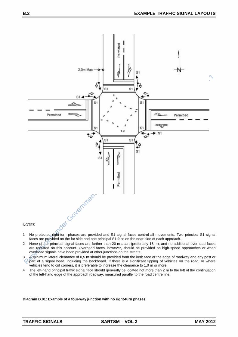
1 No protected right-turn phases are provided and S1 signal faces control all movements. Two principal S1 signal faces are provided on the far side and one principal S1 face on the near side of each approach.
2 None of the principal signal faces are further than 20 m apart (preferably 16 m), and no additional overhead faces are required on this account. Overhead faces, however, should be provided on high-speed approaches or when overhead signals have been provided at other junctions on the streets.
3 A minimum lateral clearance of 0,5 m should be provided from the kerb face or the edge of roadway and any post or part of a signal head, including the backboard. If there is a significant tipping of vehicles on the road, or where vehicles tend to cut corners, it is preferable to increase the clearance to 1,0 m or more.
4 The left-hand principal traffic signal face should generally be located not more than 2 m to the left of the continuation of the left-hand edge of the approach roadway, measured parallel to the road centre line.
Diagram B.01: Example of a four-way junction with no right-turn phases

EXAMPLE TRAFFIC SIGNAL LAYOUTS B.3
MAY 2012 SARTSM – VOL 3 TRAFFIC SIGNALS
NOTES
1 A protected/permitted right-turn phase is provided on the southern approach. This phase is controlled by two principal S10R signal faces on the far side. One of the two S10R signal faces can be provided on the near side, but in this example it is not advisable. The signal faces S1 and S10R can be replaced by single S8 faces.
2 No protected right-turn phases are provided on the other approaches and S1 signal faces control all movements. Two principal S1 signal faces are provided on the far side and one principal S1 face on the near side of each of these approaches.
3 None of the principal signal faces are further than 20 m apart (preferably 16 m), and no additional overhead faces are required on this account. Overhead faces, however, should be provided on high-speed approaches or when overhead signals have been provided at other junctions on the two streets.
Diagram B.02: Example of a four-way junction with a protected/permitted right-turn phase

B.4 EXAMPLE TRAFFIC SIGNAL LAYOUTS
TRAFFIC SIGNALS SARTSM – VOL 3 MAY 2012
NOTES
1 A protected-only right-turn phase is provided on the southern approach. This phase is controlled by two principal S1R faces combined with ST2 traffic signal arrow signs on the far side. Two of the far side S1 signal faces have been combined with ST5 traffic signal arrow signs. This combination is optional, but recommended when the S1 and S1R signal faces are erected immediately adjacent to each other.
2 No protected right-turn phases are provided on the other approaches and S1 signal faces control all movements. Two principal S1 signal faces are provided on the far side and one principal S1 face on the near side of each of these approaches.
3 None of the principal signal faces are further than 20 m apart (preferably 16 m), and no additional overhead faces are required on this account. Overhead faces, however, should be provided on high-speed approaches or when overhead signals have been provided at other junctions on the two streets.
Diagram B.03: Example of a four-way junction with a protected-only right-turn phase

EXAMPLE TRAFFIC SIGNAL LAYOUTS B.5
MAY 2012 SARTSM – VOL 3 TRAFFIC SIGNALS
NOTES
1 No protected right-turn phases are provided and S1 signal faces control all movements. All approaches have two principal S1 signal faces on the far side and one principal S1 on the near side.
2 The northern and southern approaches have a third additional principal signal face S1 mounted overhead on the far side. This signal face has been provided to meet the requirement that signal faces may not be further than 20 m apart (preferably 16 m).
3 The eastern and western approaches have not been provided with overhead signal faces since none of the principal signal faces are further than 20 m apart (preferably 16 m). Such faces, however, should be provided on high-speed approaches or when overhead signals have been provided at other junctions on the street.
Diagram B.04: Example of a wide four-way junction with no protected right-turn phases
B.6 EXAMPLE TRAFFIC SIGNAL LAYOUTS
TRAFFIC SIGNALS SARTSM – VOL 3 MAY 2012
NOTES
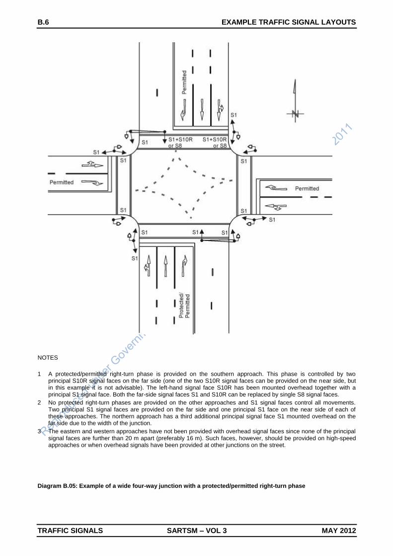
1 A protected/permitted right-turn phase is provided on the southern approach. This phase is controlled by two principal S10R signal faces on the far side (one of the two S10R signal faces can be provided on the near side, but in this example it is not advisable). The left-hand signal face S10R has been mounted overhead together with a principal S1 signal face. Both the far-side signal faces S1 and S10R can be replaced by single S8 signal faces.
2 No protected right-turn phases are provided on the other approaches and S1 signal faces control all movements. Two principal S1 signal faces are provided on the far side and one principal S1 face on the near side of each of these approaches. The northern approach has a third additional principal signal face S1 mounted overhead on the far side due to the width of the junction.
3 The eastern and western approaches have not been provided with overhead signal faces since none of the principal signal faces are further than 20 m apart (preferably 16 m). Such faces, however, should be provided on high-speed approaches or when overhead signals have been provided at other junctions on the street.
Diagram B.05: Example of a wide four-way junction with a protected/permitted right-turn phase

EXAMPLE TRAFFIC SIGNAL LAYOUTS B.7
MAY 2012 SARTSM – VOL 3 TRAFFIC SIGNALS
NOTES
1 A protected-only right-turn phase is provided on the southern approach. This phase is controlled by two principal S1R faces combined with ST2 traffic signal arrow signs on the far side. Two of the far side S1 signal faces have been combined with ST5 traffic signal arrow signs. This combination is optional, but recommended when the S1 and S1R signal faces are erected immediately adjacent to each other.
2 The left-hand signal face S1R/ST2 has been mounted overhead together with a S1/ST5 signal face. Care must be taken to ensure that the cantilever structure will be able to cope with the additional wind forces resulting from the larger size of the signal faces and arrow signs.
3 No protected right-turn phases are provided on the other approaches and S1 signal faces control all movements. Two principal S1 signal faces are provided on the far side and one principal S1 face on the near side of each of these approaches. The northern approach has a third additional principal signal face S1 mounted overhead on the far side due to the width of the junction.
4 The eastern and western approaches have not been provided with overhead signal faces since none of the principal signal faces are further than 20 m apart (preferably 16 m). Such faces, however, should be provided on high-speed approaches or when overhead signals have been provided at other junctions on the street.
Diagram B.06: Example of a wide four-way junction with a protected-only right-turn phase

B.8 EXAMPLE TRAFFIC SIGNAL LAYOUTS
TRAFFIC SIGNALS SARTSM – VOL 3 MAY 2012
NOTES
1 No protected right-turn phases are provided and S1 signal faces control all movements. All approaches have two principal S1 signal faces on the far side and one principal S1 signal face on the near side.
2 When a median is provided with adequate space, the principal S1 signal face on the far right-hand side must be placed on this median. This has been done in the above example for the northern and southern approaches.
3 The northern and southern approaches have also been provided with supplementary S1 signal faces on the far right-hand side to assist right-turning vehicles. These supplementary signal faces are not prescribed but are recommended when the signal face on the median can be blocked by heavy vehicles or buses turning right from the opposite approach.
4 None of the principal signal faces are further than 20 m apart (preferably 16 m), and no additional overhead faces are required on this account. Overhead faces, however, should be provided on high-speed approaches or when overhead signals have been provided at other junctions on the two streets.
Diagram B.07: Example of a four-way junction with a median and no protected right-turn phases

EXAMPLE TRAFFIC SIGNAL LAYOUTS B.9
MAY 2012 SARTSM – VOL 3 TRAFFIC SIGNALS
NOTES
1 Protected/permitted right-turn phases are provided on the northern and southern approaches. Two different methods for providing the principal signal phases are allowed, as shown for the two approaches. The southern approach is controlled by two principal S10R signal faces on the far side, while the northern approach is controlled by one principal S10R signal face on the far side and one on the near side. Both methods are allowed.
2 The stand-alone far-right signal face S10R should preferably be combined with an S1 signal face since no red signal is available in the S10R face. A single S8 signal face can also be used in stead of signal faces S1 and S10R.
3 The median in the north/south direction has adequate space, and the principal S1 signal face on the far right-hand side has therefore been placed on the median.
4 No protected right-turn phases are provided on the eastern and western approaches and S1 signal faces control all movements. Two principal S1 signal faces are provided on the far side and one principal S1 face on the near side of each of these approaches.
5 None of the principal signal faces are further than 20 m apart (preferably 16 m), and no additional overhead faces are required on this account. Overhead faces, however, should be provided on high-speed approaches or when overhead signals have been provided at other junctions on the two streets.
Diagram B.08: Example of a four-way junction with median and protected/permitted right-turn phases

B.10 EXAMPLE TRAFFIC SIGNAL LAYOUTS
TRAFFIC SIGNALS SARTSM – VOL 3 MAY 2012
NOTES
1 A protected-only right-turn phase is provided on the southern approach. This phase is controlled by two principal S1R faces combined with ST2 traffic signal arrow signs on the far side. One of the far-side S1 signal faces have been combined with a ST5 traffic signal arrow sign. This combination is optional, but recommended when the S1 and S1R signal faces are erected immediately adjacent to each other.
2 The median in the north/south direction has adequate space, and the principal S1 signal face on the far right-hand side has therefore been placed on the median.
3 No protected right-turn phases are provided on the other approaches and S1 signal faces control all movements. Two principal S1 signal faces are provided on the far side and one principal S1 face on the near side of each of these approaches.
4 The northern approach has been provided with a supplementary S1 signal face on the far right-hand side to assist right-turning vehicles. This supplementary signal face is not prescribed but is recommended when the signal face on the median can be blocked by heavy vehicles or buses turning right from the opposite (southern) approach.
5 None of the principal signal faces are further than 20 m apart (preferably 16 m), and no additional overhead faces are required on this account. Overhead faces, however, should be provided on high-speed approaches or when overhead signals have been provided at other junctions on the two streets.
Diagram B.09: Example of a four-way junction with a median and a protected-only right-turn phase

EXAMPLE TRAFFIC SIGNAL LAYOUTS B.11
MAY 2012 SARTSM – VOL 3 TRAFFIC SIGNALS
NOTES
1 Protected/permitted left-turn phases are provided on the southern and eastern approaches. These phases are controlled by two principal S10L signal faces, one on the near side and the second on the far side of the stop line. For the southern approach, the second principal S1L signal face has been provided on the median (this face could also have been provided on the far left-hand side of the junction).
2 Protected/permitted right-turn phases are provided on the southern and western approaches. The left-turn phase on the southern approach and the right-turn phase on the western approach operate at the same time, while the left-turn phase on the eastern approach and the right-turn phase on the southern approach operate together. The right-turn phases are controlled by two principal S10R signal faces. Some of the S1 and S10R signal faces can be replaced by single S8 signal faces.
3 The median in the east/west direction has adequate space, and the principal S1 signal faces on the far right-hand side have therefore been placed on the median.
4 The eastern approach has been provided with a supplementary S1 signal face on the far right-hand side to assist right-turning vehicles. This supplementary signal face is not prescribed but is recommended when the signal face on the median can be blocked by heavy vehicles or buses turning right from the opposite (western) approach.
Diagram B.10: Example of a four-way junction with protected left-turn phases

B.12 EXAMPLE TRAFFIC SIGNAL LAYOUTS
TRAFFIC SIGNALS SARTSM – VOL 3 MAY 2012
NOTES
1 Signalised left-turn slipways are provided on the northern and eastern approaches. Pedestrian signals have been provided on the northern slipway, but not on the eastern approach slipway.
2 All the slipways are controlled by three principal S1L signal faces, two on the far side and one on the near side. The far-side signals on the northern approach are provided on the median.
3 Protected-only right-turn phases are required on the southern and western approaches to also protect vehicles turning left on the northern and eastern approaches respectively. These phases are controlled by two principal S1R faces combined with ST2 traffic signal arrow signs on the far side. Some of the far-side S1 signal faces have been combined with a ST5 traffic signal arrow sign (such a combination is optional, but recommended when the S1 and S1R signal faces are erected immediately adjacent to each other).
4 None of the principal signal faces are further than 20 m apart (preferably 16 m), and no additional overhead faces are required on this account. Overhead faces, however, should be provided on high-speed approaches or when overhead signals have been provided at other junctions on the two streets.
Diagram B.11: Example of a four-way junction with signalised left-turn slipways

EXAMPLE TRAFFIC SIGNAL LAYOUTS B.13
MAY 2012 SARTSM – VOL 3 TRAFFIC SIGNALS
NOTES
1 Due to the wide median, sight distance for right-turn movements can be obstructed by queues of right-turning vehicles. Where possible, this problem should preferably be addressed by geometric improvements (an example of which is shown in the next diagram B.13). The problem can, however, also be addressed by providing protected-only right-turn phases (for the southern and northern approaches in the example).
2 The protected-only right-turn phases on the southern and northern approaches are controlled by two principal S1R faces combined with ST2 traffic signal arrow signs on the far side.
3 The median in the north/south direction has adequate space, and the principal S1 signal faces on the far right-hand side have therefore been placed on the median. None of these S1 signal faces have been combined with a ST5 traffic signal arrow sign. Such a combination is only recommended when the S1 and S1R signal faces are erected immediately adjacent to each other. Due to the width of the medians, the two signal faces have been erected on different signal posts.
4 No protected right-turn phases are provided on the eastern and western approaches and S1 signal faces control all movements. Two principal S1 signal faces are provided on the far side and one principal S1 face on the near side of each of these approaches.
5 None of the principal signal faces are further than 20 m apart (preferably 16 m), and no additional overhead faces are required on this account. Overhead faces, however, should be provided on high-speed approaches or when overhead signals have been provided at other junctions on the two streets.
Diagram B.12: Example of a four-way junction with very wide medians

B.14 EXAMPLE TRAFFIC SIGNAL LAYOUTS
TRAFFIC SIGNALS SARTSM – VOL 3 MAY 2012
NOTES
1 Sight distances for right-turn movements can be obstructed due to the wide median and queues of right-turn vehicles. This problem can be addressed by providing protected-only right-turn phases, but the preferred method of improvement is by providing a right-turn lane within the median as shown above.
2 The right-turn movements can be controlled as permitted movements, or by providing either protected/permitted or protected-only right-turn phases. In the example above, protected/permitted right-turn phases are provided on both the southern and northern approaches.
3 Two permissible methods for controlling the right-turn movements are shown for the southern and northern approaches. The northern approach is controlled by two principal S10R signal faces on the far side, while the southern approach is controlled by one principal S10R signal face on the far side and one on the near side. A supplementary S10R traffic signal face (together with a S1R face) is provided on the far side to improve visibility.
4 The stand-alone far-right signal face S10R should preferably be combined with an S1 signal face since no red signal is available in the S10R face. A single S8 signal face can also be used in stead of signal faces S1 and S10R.
Diagram B.13: Example of a four-way junction with a right-turn lane provided in the median

EXAMPLE TRAFFIC SIGNAL LAYOUTS B.15
MAY 2012 SARTSM – VOL 3 TRAFFIC SIGNALS
NOTES
1 This is an example of a junction of two one-way streets. No protected right-turn phases are provided or are required. Pedestrian signals and push buttons are provided.
2 The southern approach is controlled by S5 signal faces that incorporate left-turn and straight-through green arrow signal aspects. Two principal signal faces are provided on the far side and one on the near side.
3 The eastern approach is controlled by S7 signal faces that incorporate straight-through and right-turn green arrow signal aspects. Two principal signal faces are provided on the far side and one on the near side.
4 None of the principal signal faces are further than 20 m apart (preferably 16 m), and no additional overhead faces are required on this account. Overhead faces, however, should be provided on high-speed approaches or when overhead signals have been provided at other junctions on the two streets.
Diagram B.14: Example of a four-way junction between two one-way roads
B.16 EXAMPLE TRAFFIC SIGNAL LAYOUTS
TRAFFIC SIGNALS SARTSM – VOL 3 MAY 2012
NOTES
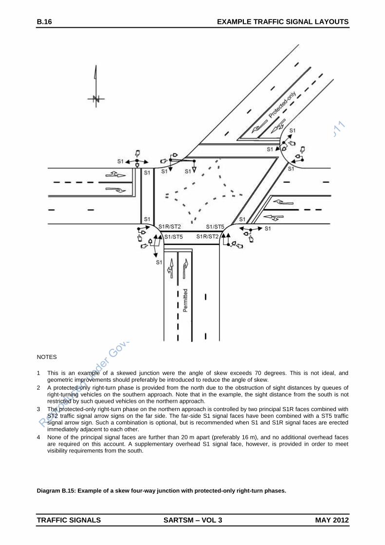
1 This is an example of a skewed junction were the angle of skew exceeds 70 degrees. This is not ideal, and geometric improvements should preferably be introduced to reduce the angle of skew.
2 A protected-only right-turn phase is provided from the north due to the obstruction of sight distances by queues of right-turning vehicles on the southern approach. Note that in the example, the sight distance from the south is not restricted by such queued vehicles on the northern approach.
3 The protected-only right-turn phase on the northern approach is controlled by two principal S1R faces combined with ST2 traffic signal arrow signs on the far side. The far-side S1 signal faces have been combined with a ST5 traffic signal arrow sign. Such a combination is optional, but is recommended when S1 and S1R signal faces are erected immediately adjacent to each other.
4 None of the principal signal faces are further than 20 m apart (preferably 16 m), and no additional overhead faces are required on this account. A supplementary overhead S1 signal face, however, is provided in order to meet visibility requirements from the south.
Diagram B.15: Example of a skew four-way junction with protected-only right-turn phases.

EXAMPLE TRAFFIC SIGNAL LAYOUTS B.17
MAY 2012 SARTSM – VOL 3 TRAFFIC SIGNALS
NOTES
1 All turning movements are controlled by S1 signal faces, except for the left-turn movement from the east. Two principal S1 signal faces are provided on the far side, and one principal S1 face on the near side of each approach.
2 The left-turn movement from the east is controlled by two principal S10L signal faces, one on the near side and one on the far side. The S1 and S10L signal faces can be replaced by combined S9 signal faces. Care must be taken that the green arrow light signal in the S10L is not flashed when a green signal is provided to a conflicting vehicular or pedestrian traffic stream.
3 The southern approach does not continue straight through the junction, and it is not possible to provide the far side principal signal faces S1 on the left- and right-hand sides of the road. The faces are therefore positioned opposite the approach lanes at locations where they are at least 3 m apart, but not further than 20 m apart. It is recommended that the left-hand face not be located further than 2 m from the continuation of the left-hand edge of the approaching roadway.
Diagram B.16: Example of a signalised T-junction

B.18 EXAMPLE TRAFFIC SIGNAL LAYOUTS
TRAFFIC SIGNALS SARTSM – VOL 3 MAY 2012
NOTES
1 The east-west road is subdivided by a constructed median that continues through the junction. The junction can therefore be treated as two separate individual T-junctions, and signal faces provided accordingly. The signals do not have to be co-ordinated and can be independently timed.
2 The two carriageways in the east-west direction can be treated as one-way roads, allowing the use of the S3 traffic signal faces. Two of the faces are provided on the far side and one on the near side as principal signal faces.
3 The pedestrian crossings in the north/south direction should be staggered to reduce the possibility of confusion when different coloured pedestrian signals are displayed in this direction.
Diagram B.17: Example of a four-way junction divided by a constructed median

EXAMPLE TRAFFIC SIGNAL LAYOUTS B.19
MAY 2012 SARTSM – VOL 3 TRAFFIC SIGNALS
NOTES
1 The above is an example of a staggered junction. Such junctions are difficult to control with traffic signals, and drivers can be confused by the operations of signals. Care must be taken that the signal is not treated as two junctions, particularly if a pedestrian crossing is provided in the middle of the junction as shown in the example.
2 The junction in the example is controlled by two vehicular signal phases operated in parallel with pedestrian phases. This may be acceptable while traffic volumes on the staggered street are low. When traffic volumes are high, each of the staggered legs may require a separate signal phase.
3 Two principal S1 signal faces are provided on the far side and one principal S1 face on the near side of each approach. Supplementary signal faces are provided for the east-west direction in the middle of the junction to improve the visibility of the signals. The far-side principal signals are situated relatively far from the stop lines, and may not be very clear to drivers. It is important to note that all the S1 signal faces in one direction must display the same red, yellow and green signal at the same time. The two far-side principal signal faces may for instance,
NOT display green light signals while red light signals are displayed by the supplementary signal faces in the middle of the junction.
Diagram B.18: Example of a staggered four-way junction
B.20 EXAMPLE TRAFFIC SIGNAL LAYOUTS
TRAFFIC SIGNALS SARTSM – VOL 3 MAY 2012
NOTES
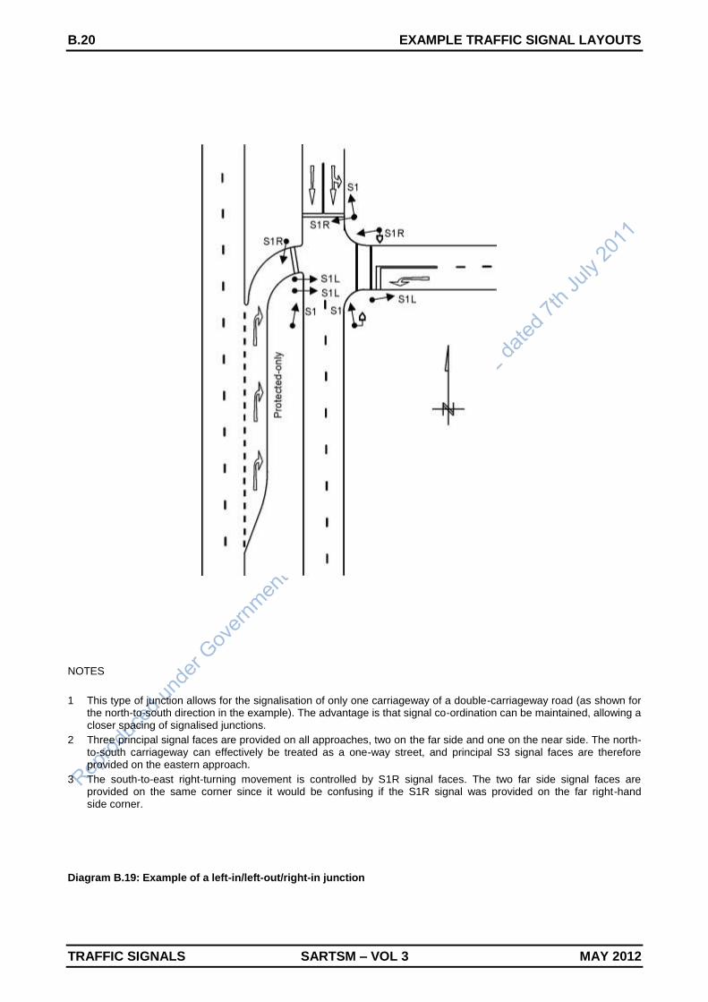
1 This type of junction allows for the signalisation of only one carriageway of a double-carriageway road (as shown for the north-to-south direction in the example). The advantage is that signal co-ordination can be maintained, allowing a closer spacing of signalised junctions.
2 Three principal signal faces are provided on all approaches, two on the far side and one on the near side. The north-to-south carriageway can effectively be treated as a one-way street, and principal S3 signal faces are therefore provided on the eastern approach.
3 The south-to-east right-turning movement is controlled by S1R signal faces. The two far side signal faces are provided on the same corner since it would be confusing if the S1R signal was provided on the far right-hand side corner.
Diagram B.19: Example of a left-in/left-out/right-in junction

EXAMPLE TRAFFIC SIGNAL LAYOUTS B.21
MAY 2012 SARTSM – VOL 3 TRAFFIC SIGNALS
NOTES
1 The “butterfly” junction allows for straight-through movement in one direction to by-pass the traffic signal (the western approach in the example). Although the layout of this type of T-junction was specifically developed for priority control, it can also be signalised.
2 The advantage of allowing the straight-through movement to by-pass the junction is that signal co-ordination can be maintained, even when traffic signals are spaced closer together. A minimum spacing, however, must still be provided to allow for weaving movements between the straight-through movement travelling from west to east and traffic turning onto the main road downstream of the junction.
3 A disadvantage of this design is that it leads to vehicle/pedestrian conflicts. Pedestrians waiting on the median tend to assume that vehicles approach the junction only from the left, without taking note or vehicles approaching from the right. The pedestrians must also cross the uncontrolled straight-through movement. The butterfly design should therefore only be considered when few pedestrians use a junction.
Diagram B.20: Example of a signalised “butterfly” T-junction

B.22 EXAMPLE TRAFFIC SIGNAL LAYOUTS
TRAFFIC SIGNALS SARTSM – VOL 3 MAY 2012

TRAFFIC SIGNAL CHECKLISTS C.1
MAY 2012 SARTSM – VOL 3 TRAFFIC SIGNALS
APPENDIX C: TRAFFIC SIGNAL CHECKLISTS
C.1 TRAFFIC SIGNAL LAYOUT CHECKLIST
SECTION REQUIREMENT CHECKED
GENERAL
1.2 Location of installation, north arrow
1.2 Drawing to scale, Scale shown
30 Version number
1.2 Signature of responsible registered professional engineer or technologist
SIGNAL WARRANTS
2.2 Minimum requirements for installation of traffic signals met
2.3 Alternatives that may obviate the need for traffic signals not viable or feasible
2.4.2 Queue length warrants met
SPEED LIMITS
3.10 Speed limits given. No limit exceeds 80 km/h
3.10 Measures on high-speed roads considered (traffic circles, etc.)
BASE PLAN
26.4 Property boundaries and fences
26.4 Roads, islands, medians and paint markings
26.4 Approach gradients
26.4 Paved sidewalks, driveways
26.4 Drainage structures
26.4 Plants and vegetation
26.4 Engineering services
26.4 Roadside furniture
26.4 Structures and buildings
GEOMETRIC DESIGN
5.2.3 Spacing of signalised junctions acceptable
5.2.4 Intersection angle minimum 70 degrees, including slipways
5.2.5 Sight distance requirements met (stopping, traffic signal faces, right-turn)
5.3.4 Right-turn sight distance adequate (particularly on wide medians/curves)
5.2.6 Design vehicle swept paths
5.2.7 Lane widths (approach and exit sides)
5.2.8 Median widths (minimum 1,2 m, but 2 m minimum when pedestrians)
5.2.9 Junction corner radius (8 to 10m radii preferred), Barrier kerbs
5.3.1 Auxiliary through lane (100 m beyond junction)
5.3.2 Left-turn lane provided when there is an opportunity for separate phase
5.3.3 Right-turn lane where possible, should be provided when speed exceeds 60 km/h
5.3.6 Auxiliary lane designs and lengths
5.3.5 Double and triple turn requirements (triple only at T-junctions and one-way streets)
5.3.7 Slipway design requirements met, 70 degrees maximum
3.3 Slipways separated from main junction by means of a constructed island
26.4 Parking space for signal maintenance vehicles

C.2 TRAFFIC SIGNAL CHECKLISTS
TRAFFIC SIGNALS SARTSM – VOL 3 MAY 2012
ROAD SIGNS AND MARKINGS
3.4 Control precedence of signs (pedestrian, bus or tram, arrows, disc light signals)
3.4/5.4 Road signs that may and may not be used with traffic signals
5.4 Pedestrian prohibited sign R218 provided where required
5.4 Traffic signal ahead warning signs provided where required (new signals, 70 km/h, etc.)
5.5.1 Stop lines
5.5.2 Pedestrian crossing lines (should be provided, except where sign R218 used)
5.5.3 Lane direction arrows
5.5.3 Regulatory road markings
5.5.4 Warning road markings
5.5.5 Guidance road markings
5.3.4 When signal face S1R used, right-turn lanes separated by painted island or similar
TRAFFIC SIGNAL FACES
3.8 Only prescribed traffic signal faces used
3.7 No duplicate light signals on one face
3.8 Signal arrow signs ST1 to ST5 only used when faces S1L and S1R used
3.8 Signal face S1 not used on same approach as S2, S3, S4, S5, S6 and S7
3.8 Signal faces S1R and S1L without ST3 and ST2 on slipways, otherwise with ST3 and ST2
3.8 Signal faces S2, S3, S4, S5, S6 and S7 only when specific turns not allowed
3.8 Signal faces S2, S6 and S7 not when there is an opposing conflicting movement
3.8 Signal faces S10R and S10L preferably not in a stand-alone location
PRINCIPAL SIGNAL FACES
1.2.4 Number, type and location of traffic signal faces
3.9.1 Two signal faces (containing red signal) on the far side of stop line
3.9.1 Additional far-side signal faces when further apart than 20 m (preferable 16 m)
3.9.1 One signal face with red signal on near side (recommended at pedestrian crossings)
3.9.1 Two faces with flashing green signals for turning phases (one far side, other far or near)
3.9.1 Far-side signal faces not nearer than 6 m from stop line (10 m preferable)
3.9.1 Far-side signal faces not less than 3 m apart, nor further than 20 m (16 m preferable)
3.9.2 Near-side signal faces not further than 3 m from stop line
SUPPLEMENTARY SIGNAL FACES
1.2.4 Number, type and location of traffic signal faces
3.11 At least two signal faces visible over minimum sight distances
3.11 At least two signal faces on far side visible over minimum distance of 50 m
3.11 At least one signal face visible in cone of vision
3.11 At least one signal face visible for right-turning vehicles waiting within junction
3.11 Additional faces provided for consistency and uniformity
3.12.3 Overhead signals on high-speed roads or to ensure consistency/uniformity
MOUNTING OF TRAFFIC SIGNAL FACES
3.11 No distracting advertisements and features near signal faces
3.12.1 Minimum clearance distance (0,5 or 0,1 m on medians when crossfalls fall away)
3.12.2 Maximum lateral distance (not further than 2 m from left edge of roadway)
3.12.5 Overhead signals on left-hand side of road

MAY 2012 SARTSM – VOL 3 TRAFFIC SIGNALS
PEDESTRIAN AND PEDAL CYCLIST SIGNALS
1.2 Number, type and location of pedestrian signal faces
4.6 Location of pedestrian signal faces
4.3 Push buttons provided and pedestrian signals demand dependent
4.7 Push button locations and directions
4.6 Staggered crossing considered
SIGNAL ASPECTS AND POSTS
16.2.2 Luminous intensity (normal or high – high on roads with speed limit 70 km/h or greater)
16.2.3 Aspect sizes (210 or 300 mm)
16.3 Signal louvres and visors
16.4 Background screens (optionally with white retro-reflective borders)
16.5 Yellow retro-reflective strips for signal posts (optional)
VEHICLE DETECTION
7 Vehicle-actuated control type and methodology
7.8/20.5 Number, type and location of vehicle detectors
20.4 Detector operations (latching or non-latching)
CONTROLLER AND ELECTRICAL
18.7 Location of controller (according to requirements)
22 Source of power
22.4 Cable ducts and draw boxes
22.2 Wiring, Number of cores
5.6 Road lighting considered
REMARKS
Consulting
Engineer
DESIGNED BY
Signed Responsible
Authority
APPROVED BY
Signed
N/S Street
&
E/W Street Name Name
Position Position
Registration Registration Intersection No
NNNN Date Date

C.4 TRAFFIC SIGNAL CHECKLISTS
TRAFFIC SIGNALS SARTSM – VOL 3 MAY 2012
C.2 TRAFFIC SIGNAL PHASING AND TIMING CHECKLIST
SECTION REQUIREMENT CHECKED
GENERAL
1.2/6.16 Signal configuration diagrams provided
30 Version number
1.2 Diagrams signed by responsible engineer or technologist
TRAFFIC LIGHT SIGNALS
3.5.1 Basic sequence of light signals (green, yellow, red)
3.5.1 Differently coloured signals not displayed together to the same movement
3.5.3/6.8 Yellow signal not to right-turn movement at same time as opposing traffic receives green
3.5.1 Yellow arrow may be omitted under specific circumstances
3.5.1 Yellow signals not in flashing mode
3.5.4 Steady green right arrow not used when there is an opposing movement
3.5.4 Steady green arrow and green disc light signals not displayed on the same approach
3.5.4 Flashing green arrows not used when there is an opposing movement
3.5.4 Pedestrian signals recommended when flashing green arrows used
3.5 Green light signal not used in both steady and flashing modes
3.6 No flashing signals in place of normal traffic signal operations
3.6 Start-up procedure for traffic signals
PEDESTRIAN AND PEDAL CYCLISTS
4.3.2 Pedestrian green – 4 to 7 seconds
4.3.3 Pedestrian walking speed of 1,2 or 1,0 m/s
4.3.3 Flashing red man reduced and replaced by steady red man (max 75% or intergreen)
4.3.3 Flashing red man terminate before parallel all-red period
4.3.3 Pedestrian green phase not in conflict with flashing vehicular green
TRAFFIC SIGNAL TIMING AND PHASING
6.6 Recent traffic counts, Counts to standards
6.5 Signal timing plans
6.9 Left-turn phases (check pedestrians)
6.10/6.11 Right-turn phases where required
5.3.7 Protected-only right-turn phase when signalised slipway provided
6.10.3 Leading/lagging right-turn phase appropriate, single lagging right-turn phase checked
3.5.4 Green light signals minimum safety requirements
3.5/6.12 Yellow and all-red intervals
6.12.4/6.8 Longer all-red intervals on slipways (and when main phase followed by left-turn phase)
6.13.4 Critical movement analysis used in signal timings
6.14 Signal co-ordination acceptable (queues and platoon dispersion taken into account)
6.14.6 Progression speed acceptable, possibility of speeding checked
6.14.8 Possibility of obstructive (damaging) queue lengths checked
REMARKS
Consulting
Engineer
INSPECTED BY
Signed Responsible
Authority
APPROVED BY
Signed
N/S Street
&
E/W Street Name Name
Position Position
Registration Registration Intersection No
NNNN Date Date

MAY 2012 SARTSM – VOL 3 TRAFFIC SIGNALS
C.3 TRAFFIC SIGNAL COMMISSIONING CHECKLIST
SECTION REQUIREMENT CHECKED
GENERAL
1.2 As-built layout plans and timing diagrams, Modifications shown and approved
1.2 Layout plans and timing diagrams signed by responsible engineer or technologist
GEOMETRIC DESIGN, ROAD SIGNS AND CIVIL ENGINEERING
5 Layout and geometric design of junction or crossing
5 Road works as per civil engineering requirements
5 Road signs and markings
5 Parking space for signal maintenance vehicles
5 Final clean up and finishing off, removal of waste material
TRAFFIC SIGNAL HEADS AND FACES
3.5.1 Signal heads masked out during installation, and other junction control in place
3 Types of traffic signal faces, signal symbols (disc, arrow, etc.)
16.4 Background screens (backboards) provided, white retro-reflective border if specified
16.2.3 Signal aspect sizes, lenses, reflectors
16.3 Signal visors (and louvres)
16.2.2 Luminous intensity (normal or high)
3.11 Alignment of signal axis
3.11 Signal faces intended for specific movements not be mistaken by other movements
3.7 All vehicular light signals on same horizontal level
Installation, damage, cleanliness, etc.
POSITION OF SIGNAL HEADS AND FACES
3 Locations and directions of traffic signal faces
3.9.1 Far-side signal faces not nearer than 6 m from stop line (10 m preferable)
3.9.1 Far-side signal faces not less than 3 m apart, nor further than 20 m (16 m preferable)
3.9.2 Near-side signal faces not further than 3 m from stop line
3.12.1 Minimum clearance distance - 0,5 or 0,1 m on medians where crossfall falls away
3.12.2 Maximum lateral distance - not further than 2 m from left edge of roadway
3.12.2 Post minimum/maximum mounting heights - 2,3 m/3,0 m – 2,1 m pedestrian minimum
3.12.2 Totem mounting heights - 1 m separation
3.12.2 Overhead minimum/maximum clearance/mounting heights - 5,2 m/6,2 m
3.12.5 Overhead preferably on left-hand side of road
PEDESTRIAN SIGNAL FACES AND PUSH BUTTONS
4.6 Locations and directions of pedestrian signal heads
4.7 Red man signal not higher than vehicular green signal (may be on the same height)
4.7 Location and directions of push buttons, 1,1 m heights
4.7 Pedestrian symbols on push buttons
Correct operation by testing each button
Installation, damage
SIGNAL POSTS
16.5 Foundations, anchor bolts, size and depth, backfill, concrete strength (where used)
Conduit entry, capping before pouring of concrete
Vertical alignment of posts, cantilevers and gantries
16.5 Yellow retro-reflectorised strips provided if specified
Paint work, damage

C.6 TRAFFIC SIGNAL CHECKLISTS
TRAFFIC SIGNALS SARTSM – VOL 3 MAY 2012
VEHICLE DETECTORS (CHECKED DURING INSTALLATION)
20.5.2 Location, dimensions and layout
20.5.3 Saw cut width and depth. Debris, dirt and moisture removed
20.5.3 Correct loop wiring, no splicing, no damage, no sharp corners, correct depth
20.5.3 Proper sealing of slot, proper adherence to pavement
20.5 Correct operation by using actual vehicle or a metal sheet that simulates a vehicle
TRAFFIC SIGNAL CONTROLLER
18.7 Location of controller
Foundation and fixing, alignment
18 Controller type
Cables entering cabinet (adequately sealed)
18.7 Sealing and waterproofing, operation of cabinet doors
Cleanliness, damage, paint work
6 Operation, signal plans, phases and timing, co-ordination, fallback plan
Manual control panel operation
19.5 Communication with central control system, synchronisation
18.4 Conflict monitoring
18 Signal start-up sequence, Restart after power failure (retention of signal timings)
18.5 Fault monitoring, red lamp monitoring
30 Maintenance record in cabinet
DUCTS, DRAW BOXES AND TRENCHES (CHECKED DURING CONSTRUCTION)
22 Location and sizes, materials, damage and cleanliness
22 Provision of draw wire in all ducts
22 Excavation trench width and depth, preparation of trenches and beds
22 Compaction of excavations, backfill material, Asphalt reinstatement
26 Sidewalks, paving, plants and grass
26 Damaged services
ELECTRICAL (ALL ELECTRICAL WORK TO BE APPROVED BY A QUALIFIED ELECTRICIAN)
22 Power supply (source of power)
22 Earthing, ground rods
Conduits - size and type, collapsed sections, bending, joints
Cables and wiring, colour coding and tags, damage.
22 Provision of drip loops
22 No unauthorised splicing of cables
Wiring tested for continuity and electrical leaks
22 Wiring certificate issued
REMARKS
Consulting
Engineer
INSPECTED BY
Signed Responsible
Authority
APPROVED BY
Signed
N/S Street
&
E/W Street Name Name
Position Position
Registration Registration Intersection No
NNNN Date Date

SOUTH AFRICAN
ROAD TRAFFIC SIGNS MANUAL
VOLUME 3: TRAFFIC SIGNAL DESIGN
APPENDIX D
TRAFFIC SIGNAL FORMS
DIGITISED VERSION – May 2012


Layout Plan
Signal face types shown together with signal groups (between parentheses)
Legend
Scale
DESIGNED BY
Signed
APPROVED BY
Signed
Name Name
Position Position
Registration Registration Intersection No
Date Date

Layout Plan
(Signal groups given between parentheses)
Legend
Scale
DESIGNED BY
Signed
APPROVED BY
Signed
Name Name
Position Position
Registration Registration Intersection No
Date Date

Signal groups and staging
Signal groups [SANS phases]
Signal staging (showing signal groups)
Stage 1 Stage 2 Stage 3 Stage 4
Stage 5 Stage 6 Stage 7 Stage 8
Notes – Stage 1 should be selected as the first permanently available stage, preferably on the main road.
Stages given and numbered in the sequence they will be displayed.
DESIGNED BY
Signed
APPROVED BY
Signed
Name Name
Position Position
Registration Registration Junction No: Date Date
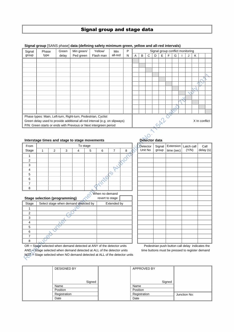
Signal group and stage data
Signal group [SANS phase] data (defining safety minimum green, yellow and all-red intervals)
Signal group
Phase type
Green
delay
Min green/
Ped green
Yellow/
Flash man
Min all-red
P
N
Signal group conflict monitoring
A B C D E F G I J K
Phase types: Main, Left-turn, Right-turn, Pedestrian, Cyclist
Green delay used to provide additional all-red interval (e.g. on slipways)
P/N: Green starts or ends with Previous or Next intergreen period
X In conflict
Interstage times and stage to stage movements
Detector data
From
Stage
To stage
Detector Unit No
Signal group
Extension
time (sec)
Latch call (Y/N)
Call delay (s) 1 2 3 4 5 6 7 8
1
2
3
4
5
6
7
8
Stage selection (programming)
When no demand
revert to stage
Stage Select stage when demand detected by Extended by
1
2
3
4
5
6
7
8
OR = Stage selected when demand detected at ANY of the detector units
AND = Stage selected when demand detected at ALL of the detector units
NOT = Stage selected when NO demand detected at ALL of the detector units
Pedestrian push button call delay indicates the
time buttons must be pressed to register demand
DESIGNED BY
Signed
APPROVED BY
Signed
Name Name
Position Position
Registration Registration Junction No: Date Date

Signal plans and timings
Event table
Fallback Plan No
Day of week Start time
End time
Plan No
Offset Stage 1
Day of week Start time
End time
Plan No
Offset Stage 1
Signal plans and timings
Plan No
Mode Stage
1 Stage
2 Stage
3 Stage
4 Stage
5 Stage
6 Stage
7 Stage
8 Cycle length
1 Min green
Max green
Perm/Skip
2 Min green
Max green
Perm/Skip
3 Min green
Max green
Perm/Skip
4 Min green
Max green
Perm/Skip
5 Min green
Max green
Perm/Skip
6 Min green
Max green
Perm/Skip
7 Min green
Max green
Perm/Skip
8 Min green
Max green
Perm/Skip
9 Min green
Max green
Perm/Skip
10 Min green
Max green
Perm/Skip
Modes: Fixed time, Linked fixed time, Fully-VA, Semi-VA, Linked semi-VA.
P = Permanent, S= Skip stage
(Linked semi-VA: Extend stage number)
DESIGNED BY
Signed
APPROVED BY
Signed
Name Name
Position Position
Registration Registration Junction No: Date Date

TRAFFIC SIGNAL LAYOUT CHECKLIST (1/3)
SECTION REQUIREMENT CHECKED
GENERAL
1.2 Location of installation, north arrow
1.2 Drawing to scale, Scale shown
30 Version number
1.2 Signature of responsible registered professional engineer or technologist
SIGNAL WARRANTS
2.2 Minimum requirements for installation of traffic signals met
2.3 Alternatives that may obviate the need for traffic signals not viable or feasible
2.4.2 Queue length warrants met
SPEED LIMITS
3.10 Speed limits given. No limit exceeds 80 km/h
3.10 Measures on high-speed roads considered (traffic circles, etc.)
BASE PLAN
26.4 Property boundaries and fences
26.4 Roads, islands, medians and paint markings
26.4 Approach gradients
26.4 Paved sidewalks, driveways
26.4 Drainage structures
26.4 Plants and vegetation
26.4 Engineering services
26.4 Roadside furniture
26.4 Structures and buildings
GEOMETRIC DESIGN
5.2.3 Spacing of signalised junctions acceptable
5.2.4 Intersection angle minimum 70 degrees, including slipways
5.2.5 Sight distance requirements met (stopping, traffic signal faces, right-turn)
5.3.4 Right-turn sight distance adequate (particularly on wide medians/curves)
5.2.6 Design vehicle swept paths
5.2.7 Lane widths (approach and exit sides)
5.2.8 Median widths (minimum 1,2 m, but 2 m minimum when pedestrians)
5.2.9 Junction corner radius (8 to 10m radii preferred), Barrier kerbs
5.3.1 Auxiliary through lane (100 m beyond junction)
5.3.2 Left-turn lane provided when there is an opportunity for separate phase
5.3.3 Right-turn lane where possible, should be provided when speed exceeds 60 km/h
5.3.6 Auxiliary lane designs and lengths
5.3.5 Double and triple turn requirements (triple only at T-junctions and one-way streets)
5.3.7 Slipway design requirements met, 70 degrees maximum
3.3 Slipways separated from main junction by means of a constructed island
26.4 Parking space for signal maintenance vehicles
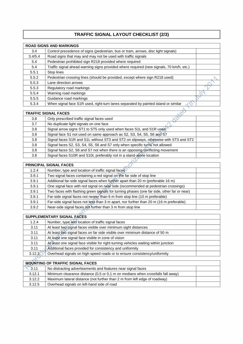
TRAFFIC SIGNAL LAYOUT CHECKLIST (2/3)
ROAD SIGNS AND MARKINGS
3.4 Control precedence of signs (pedestrian, bus or tram, arrows, disc light signals)
3.4/5.4 Road signs that may and may not be used with traffic signals
5.4 Pedestrian prohibited sign R218 provided where required
5.4 Traffic signal ahead warning signs provided where required (new signals, 70 km/h, etc.)
5.5.1 Stop lines
5.5.2 Pedestrian crossing lines (should be provided, except where sign R218 used)
5.5.3 Lane direction arrows
5.5.3 Regulatory road markings
5.5.4 Warning road markings
5.5.5 Guidance road markings
5.3.4 When signal face S1R used, right-turn lanes separated by painted island or similar
TRAFFIC SIGNAL FACES
3.8 Only prescribed traffic signal faces used
3.7 No duplicate light signals on one face
3.8 Signal arrow signs ST1 to ST5 only used when faces S1L and S1R used
3.8 Signal face S1 not used on same approach as S2, S3, S4, S5, S6 and S7
3.8 Signal faces S1R and S1L without ST3 and ST2 on slipways, otherwise with ST3 and ST2
3.8 Signal faces S2, S3, S4, S5, S6 and S7 only when specific turns not allowed
3.8 Signal faces S2, S6 and S7 not when there is an opposing conflicting movement
3.8 Signal faces S10R and S10L preferably not in a stand-alone location
PRINCIPAL SIGNAL FACES
1.2.4 Number, type and location of traffic signal faces
3.9.1 Two signal faces containing a red signal on the far side of stop line
3.9.1 Additional far-side signal faces when further apart than 20 m (preferable 16 m)
3.9.1 One signal face with red signal on near side (recommended at pedestrian crossings)
3.9.1 Two faces with flashing green signals for turning phases (one far side, other far or near)
3.9.1 Far-side signal faces not nearer than 6 m from stop line (10 m preferable)
3.9.1 Far-side signal faces not less than 3 m apart, nor further than 20 m (16 m preferable)
3.9.2 Near-side signal faces not further than 3 m from stop line
SUPPLEMENTARY SIGNAL FACES
1.2.4 Number, type and location of traffic signal faces
3.11 At least two signal faces visible over minimum sight distances
3.11 At least two signal faces on far side visible over minimum distance of 50 m
3.11 At least one signal face visible in cone of vision
3.11 At least one signal face visible for right-turning vehicles waiting within junction
3.11 Additional faces provided for consistency and uniformity
3.12.3 Overhead signals on high-speed roads or to ensure consistency/uniformity
MOUNTING OF TRAFFIC SIGNAL FACES
3.11 No distracting advertisements and features near signal faces
3.12.1 Minimum clearance distance (0,5 or 0,1 m on medians when crossfalls fall away)
3.12.2 Maximum lateral distance (not further than 2 m from left edge of roadway)
3.12.5 Overhead signals on left-hand side of road

TRAFFIC SIGNAL LAYOUT CHECKLIST (3/3)
PEDESTRIAN AND PEDAL CYCLIST SIGNALS
1.2 Number, type and location of pedestrian signal faces
4.6 Location of pedestrian signal faces
4.3 Push buttons provided and pedestrian signals demand dependent
4.7 Push button locations and directions
4.6 Staggered crossing considered
SIGNAL ASPECTS AND POSTS
16.2.2 Luminous intensity (normal or high – high on roads with speed limit 70 km/h or greater)
16.2.3 Aspect sizes (210 or 300 mm)
16.3 Signal louvres and visors
16.4 Background screens (optionally with white retro-reflective borders)
16.5 Yellow retro-reflective strips for signal posts (optional)
VEHICLE DETECTION
7 Vehicle-actuated control type and methodology
7.8/20.5 Number, type and location of vehicle detectors
20.4 Detector operations (latching or non-latching)
CONTROLLER AND ELECTRICAL
18.7 Location of controller (according to requirements)
22 Source of power
22.4 Cable ducts and draw boxes
22.2 Wiring, Number of cores
5.6 Road lighting considered
REMARKS
DESIGNED BY
Signed
APPROVED BY
Signed
Name Name
Position Position
Registration Registration Intersection No
Date Date
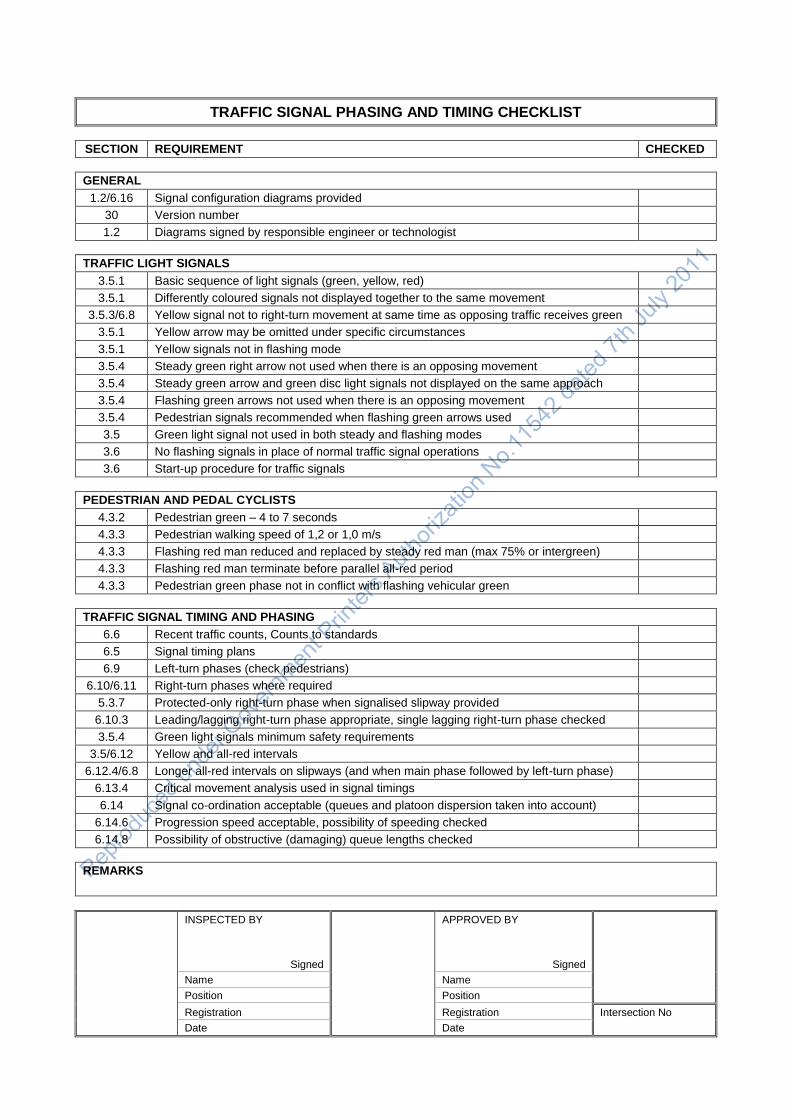
TRAFFIC SIGNAL PHASING AND TIMING CHECKLIST
SECTION REQUIREMENT CHECKED
GENERAL
1.2/6.16 Signal configuration diagrams provided
30 Version number
1.2 Diagrams signed by responsible engineer or technologist
TRAFFIC LIGHT SIGNALS
3.5.1 Basic sequence of light signals (green, yellow, red)
3.5.1 Differently coloured signals not displayed together to the same movement
3.5.3/6.8 Yellow signal not to right-turn movement at same time as opposing traffic receives green
3.5.1 Yellow arrow may be omitted under specific circumstances
3.5.1 Yellow signals not in flashing mode
3.5.4 Steady green right arrow not used when there is an opposing movement
3.5.4 Steady green arrow and green disc light signals not displayed on the same approach
3.5.4 Flashing green arrows not used when there is an opposing movement
3.5.4 Pedestrian signals recommended when flashing green arrows used
3.5 Green light signal not used in both steady and flashing modes
3.6 No flashing signals in place of normal traffic signal operations
3.6 Start-up procedure for traffic signals
PEDESTRIAN AND PEDAL CYCLISTS
4.3.2 Pedestrian green – 4 to 7 seconds
4.3.3 Pedestrian walking speed of 1,2 or 1,0 m/s
4.3.3 Flashing red man reduced and replaced by steady red man (max 75% or intergreen)
4.3.3 Flashing red man terminate before parallel all-red period
4.3.3 Pedestrian green phase not in conflict with flashing vehicular green
TRAFFIC SIGNAL TIMING AND PHASING
6.6 Recent traffic counts, Counts to standards
6.5 Signal timing plans
6.9 Left-turn phases (check pedestrians)
6.10/6.11 Right-turn phases where required
5.3.7 Protected-only right-turn phase when signalised slipway provided
6.10.3 Leading/lagging right-turn phase appropriate, single lagging right-turn phase checked
3.5.4 Green light signals minimum safety requirements
3.5/6.12 Yellow and all-red intervals
6.12.4/6.8 Longer all-red intervals on slipways (and when main phase followed by left-turn phase)
6.13.4 Critical movement analysis used in signal timings
6.14 Signal co-ordination acceptable (queues and platoon dispersion taken into account)
6.14.6 Progression speed acceptable, possibility of speeding checked
6.14.8 Possibility of obstructive (damaging) queue lengths checked
REMARKS
INSPECTED BY
Signed
APPROVED BY
Signed
Name Name
Position Position
Registration Registration Intersection No
Date Date

TRAFFIC SIGNAL COMMISSIONING CHECKLIST (1/2)
SECTION REQUIREMENT CHECKED
GENERAL
1.2 As-built layout plans and timing diagrams, Modifications shown and approved
1.2 Layout plans and timing diagrams signed by responsible engineer or technologist
GEOMETRIC DESIGN, ROAD SIGNS AND CIVIL ENGINEERING
5 Layout and geometric design of junction or crossing
5 Road works as per civil engineering requirements
5 Road signs and markings
5 Parking space for signal maintenance vehicles
5 Final clean up and finishing off, removal of waste material
TRAFFIC SIGNAL HEADS AND FACES
3.5.1 Signal heads masked out during installation, and other junction control in place
3 Types of traffic signal faces, signal symbols (disc, arrow, etc.)
16.4 Background screens (backboards) provided, white retro-reflective border if specified
16.2.3 Signal aspect sizes, lenses, reflectors
16.3 Signal visors (and louvres)
16.2.2 Luminous intensity (normal or high)
3.11 Alignment of signal axis
3.11 Signal faces intended for specific movements not be mistaken by other movements
3.7 All vehicular light signals on same horizontal level
Installation, damage, cleanliness, etc.
POSITION OF SIGNAL HEADS AND FACES
3 Locations and directions of traffic signal faces
3.9.1 Far-side signal faces not nearer than 6 m from stop line (10 m preferable)
3.9.1 Far-side signal faces not less than 3 m apart, nor further than 20 m (16 m preferable)
3.9.2 Near-side signal faces not further than 3 m from stop line
3.12.1 Minimum clearance distance - 0,5 or 0,1 m on medians where crossfall falls away
3.12.2 Maximum lateral distance - not further than 2 m from left edge of roadway
3.12.2 Post minimum/maximum mounting heights - 2,3 m/3,0 m – 2,1 m pedestrian minimum
3.12.2 Totem mounting heights - 1 m separation
3.12.2 Overhead minimum/maximum clearance/mounting heights - 5,2 m/6,2 m
3.12.5 Overhead preferably on left-hand side of road
PEDESTRIAN SIGNAL FACES AND PUSH BUTTONS
4.6 Locations and directions of pedestrian signal heads
4.7 Red man signal not higher than vehicular green signal (may be on the same height)
4.7 Location and directions of push buttons, 1,1 m heights
4.7 Pedestrian symbols on push buttons
Correct operation by testing each button
Installation, damage
SIGNAL POSTS
16.5 Foundations, anchor bolts, size and depth, backfill, concrete strength (where used)
Conduit entry, capping before pouring of concrete
Vertical alignment of posts, cantilevers and gantries
16.5 Yellow retro-reflectorised strips provided if specified
Paint work, damage

TRAFFIC SIGNAL COMMISSIONING CHECKLIST (1/2)
VEHICLE DETECTORS (CHECKED DURING INSTALLATION)
20.5.2 Location, dimensions and layout
20.5.3 Saw cut width and depth. Debris, dirt and moisture removed
20.5.3 Correct loop wiring, no splicing, no damage, no sharp corners, correct depth
20.5.3 Proper sealing of slot, proper adherence to pavement
20.5 Correct operation by using actual vehicle or a metal sheet that simulates a vehicle
TRAFFIC SIGNAL CONTROLLER
18.7 Location of controller
Foundation and fixing, alignment
18 Controller type
Cables entering cabinet (adequately sealed)
18.7 Sealing and waterproofing, operation of cabinet doors
Cleanliness, damage, paint work
6 Operation, signal plans, phases and timing, co-ordination, fallback plan
Manual control panel operation
19.5 Communication with central control system, synchronisation
18.4 Conflict monitoring
18 Signal start-up sequence, Restart after power failure (retention of signal timings)
18.5 Fault monitoring, red lamp monitoring
30 Maintenance record in cabinet
DUCTS, DRAW BOXES AND TRENCHES (CHECKED DURING CONSTRUCTION)
22 Location and sizes, materials, damage and cleanliness
22 Provision of draw wire in all ducts
22 Excavation trench width and depth, preparation of trenches and beds
22 Compaction of excavations, backfill material, Asphalt reinstatement
26 Sidewalks, paving, plants and grass
26 Damaged services
ELECTRICAL (ALL ELECTRICAL WORK TO BE APPROVED BY A QUALIFIED ELECTRICIAN)
22 Power supply (source of power)
22 Earthing, ground rods
Conduits - size and type, collapsed sections, bending, joints
Cables and wiring, colour coding and tags, damage.
22 Provision of drip loops
22 No unauthorised splicing of cables
Wiring tested for continuity and electrical leaks
22 Wiring certificate issued
REMARKS
INSPECTED BY
Signed
APPROVED BY
Signed
Name Name
Position Position
Registration Registration Intersection No
Date Date