Interconnection Guidelines for Transmission Interconnected Producer Owned Generation

SECTION 3
Electric Transmission Interconnection
3.1 Electric Transmission Interconnection GWF Energy LLC proposes to modify the existing Tracy Peaker Project (TPP), a nominal 169-megawatt (MW) simple-cycle power plant, by converting the facility into a combined-cycle power plant with a nominal 145 MW of additional net plant generating capacity. The modifications to the existing facility will be referred to hereinafter as the GWF Tracy Combined Cycle Power Plant (GWF Tracy). The new steam turbine generator (STG) would be connected to an individual, dedicated, three-phase generation step-up (GSU) transformer that would be connected to the existing 115-kV onsite Tracy Switchyard bus via a short span of overhead transmission line. From the Tracy Switchyard, the generated power would be connected to the regional electric grid via the existing onsite 115-kV overhead transmission tie-line and the existing Pacific Gas and Electric Company (PG&E) Schulte Switching Station located on the GWF Tracy site.
To interconnect the new generation, PG&E will loop the Tesla-Manteca 115-kV transmission line adjacent to the site into the onsite PG&E Schulte Switching Station. The single line diagram showing this interconnection is provided as Figure 5-2 in Appendix 3A. Three segments of the existing 115-kV transmission system, shown in Figure 1.1-3, would be reconductored downstream of the first point of interconnection to accommodate the additional power output. Power would then be routed via existing transmission lines to PG&E’s Tesla, Kasson, and Manteca Substations approximately five miles away. The interconnection to the PG&E transmission lines is shown on Figure 3.1-1. Five hard copies of the Interconnection System Impact Study for the 115-kV system have been submitted under a separate cover with this Application for Certification. Electronic copies of this Application for Certification include the Interconnection System Impact Study as Appendix 3A.
3.2 Transmission System Engineering 3.2.1 Existing Facilities GWF has received the competed System Impact Study (SIS) from the California Independent Systems Operator and PG&E. The SIS performs an evaluation of the existing transmission facilities near GWF Tracy to identify transmission lines with adequate capacity to accommodate the output of the proposed plant. The existing transmission facilities in the area that are impacted by GWF Tracy include the following:
• PG&E 115-kV Schulte-Lammers line that runs between the Lammers Substation and the Owens Tap #1. See Figure 1.1-3 Segment 1.
• PG&E 115-kV Vierra-Tracy-Kasson line that runs between Cross Road Junction and Kasson Junction #2. See Figure 1.1-3 Segments 2 and 3.
SAC/365887/080740007 (GWF_TRACY_3_ELECTRIC_TRANSMISSION_INTERCONNECTION.DOC) 3-1
SECTION 3: ELECTRIC TRANSMISSION INTERCONNETION
3.2.2 Proposed Facilities 3.2.2.1 GWF Tracy Switchyards GWF Tracy presently includes two onsite switchyards. One switchyard is owned by GWF and is called the Tracy Switchyard. The point of delivery switchyard is owned by PG&E and is called the PG&E Schulte Switching Station. The two switchyards are connected by an onsite 735-foot tie-line, as shown on Figure 6-1 in the 2001 TPP AFC (see Appendix 1A).
The 115-kV Tracy Switchyard is on the south side of the GWF Tracy site. The switchyard has a two-breaker radial bus configuration connecting the two 84.4-MW combustion turbine generators (CTGs), one position for each unit. Additional power would be generated by a 145-MW STG at 18 kV and then stepped up to 115 kV by a dedicated GSU transformer near the STG. If necessary, firewalls would be installed between the new STG transformer and the existing CTG transformers to protect from a fire at adjacent transformers. The firewall would also offer a degree of protection to other equipment and structures in the immediate area. Surge arresters would be provided at the high-voltage bushings to protect the transformer from surges on the 115-kV transmission system caused by lightning strikes or other system disturbances. The high-voltage terminals of the new GSU transformer would connect to the Tracy Switchyard via a 250-foot overhead tie-line, high-voltage circuit breaker, and associated disconnect switches. The new breaker and switches would be located in a fenced area adjacent to the new STG transformer. The new tie-line between the STG transformer and the Tracy Switchyard would use tubular steel pole dead-end-type structures with vertical conductor attachments and polymer dead-end conductor insulators, similar to the existing tie line and as shown on Figure 3.1-2. The tie-line would use a single 954-kcmil aluminum conductor steel reinforced per phase. This conductor has a normal current rating of 830 amperes. The normal rating is based on a conductor temperature of 176 degrees Fahrenheit (°F), (80 degrees Celsius [°C]), ambient temperature of 104°F (40°C), a 2 feet per second (fps) crosswind, and an emissivity factor of 0.50 with sun. The tubular steel pole structures are supported by anchor-bolted foundations.
The 115-kV PG&E Schulte Switching Station is on the east side of the GWF Tracy site. This station presently has a three-position ring bus configuration. Two bus positions are for the Tesla-Kasson 115-kV transmission line loop-through, and the remaining bus position is for the tie-line connection to the Tracy Switchyard. The three-position ring bus configuration would be converted to a three bay, breaker-and-a-half bus configuration to accommodate the loop through the 115-kV Tesla-Manteca transmission line.
The Tracy Switchyard and the PG&E Schulte Switching Station are connected with an onsite 735-foot tie-line. The tie-line utilizes tubular steel pole dead-end-type structures with vertical conductor attachments using polymer dead-end conductor insulators, as shown on Figure 3.1-2. The tubular steel pole structures are supported by anchor-bolted foundations.
The tie-line presently uses a single 1,590-kcmil, all aluminum conductor “Falcon” per phase. This conductor has a maximum current rating of 1,495 amperes determined from PLS-CADD Version 8.21+, based on a conductor temperature of 212°F, (100°C), ambient temperature of 104°F (40°C), a 2 fps crosswind, and an emissivity factor of 0.50 with sun. The tie-line would be reconductored using a single 1,431-kcmil, aluminum-conductor, steel-supported (ACSS) “Bobolink” per phase. This high-temperature conductor has a maximum current rating of 2,303 amperes determined from PLS-CADD Version 8.21+,
3-2 SAC/365887/080740007 (GWF_TRACY_3_ELECTRIC_TRANSMISSION_INTERCONNECTION.DOC)

SECTION 3: ELECTRIC TRANSMISSION INTERCONNETION
based on a conductor temperature of 392°F, (200°C), ambient temperature of 104 °F (40°C), a 2 fps crosswind, and an emissivity factor of 0.50 with sun.
The modifications to the Tracy Switchyard and the PG&E Schulte Switching Station would be designed in accordance with applicable industry standards and would have the following ratings:
• Nominal voltage: 115 kV • Basic impulse level: 550 kV • Continuous current: 2,000 amperes • Short-circuit current, included in PG&E’s System Impact Study
The Tracy Switchyard uses a strain-bus design supported by galvanized-steel structures and the modifications and additions to the PG&E Schulte Switching Station would use a conventional outdoor-air-insulated rigid-bus design supported on galvanized-steel structures.
Both switchyards are fenced with a galvanized-steel, chain-link fabric of a typical height and no new fencing in these areas would be required. All nongalvanized structures and equipment are painted shades of ANSI gray. The color of the control building is similar to that of the GWF Tracy power generation facility.
The existing ground mats of both switchyards would be extended, if necessary, into the areas of new installations to provide safe step-and-touch potentials for the general public and switchyard operation and maintenance personnel. The modified grounding system would be designed in accordance with American National Standards Institute/Institute of Electrical and Electronics Engineers (ANSI/IEEE) 80.
The switchyards existing alternating current (AC) station service system would be expanded to meet the needs of the expanded switchyards. The existing direct current (DC) station service system would meet the load requirements of the expanded switchyards.
3.2.2.2 GWF Tracy Tesla-Manteca 115-kV Interconnection The Tesla-Manteca 115-kV transmission line would be opened directly adjacent to the GWF Tracy site and looped into the existing onsite PG&E Schulte Switching Station as shown on Figure 3.1-1.
The tubular steel dead-end structures for the proposed loop-through line would consist of a tapered tubular steel poles and polymer dead-end conductor insulators, similar to the structure shown on Figure 3.1-2 but with a height of between 40 and 50 feet. The tubular steel dead-end structures would be supported by anchor-bolted foundations.
The proposed transmission line loop-through span is expected to be approximately 120 to 200 feet in length. The structure heights selected would provide a minimum ground clearance of 30 feet at 60 °F and 28.5 feet at 130°F, in accordance with the requirements of California Public Utilities Commission (CPUC) General Order No. 95 (GO-95).
The proposed loop-through line would use a single 477-kcmil ACSS “Flicker” per phase. This conductor has a normal current rating of 1,205 amperes. The normal conductor rating was determined from Alcoa’s T&D Conductors, Overhead Underground handbook, based on a
SAC/365887/080740007 (GWF_TRACY_3_ELECTRIC_TRANSMISSION_INTERCONNECTION.DOC) 3-3

SECTION 3: ELECTRIC TRANSMISSION INTERCONNETION
conductor temperature rise of 40°C above a 40°C ambient temperature, a 2 fps crosswind, and an emissivity factor of 0.50 without sun.
3.2.2.3 Other Typical industry design, operation, or maintenance practices would be required for the proposed switchyard and transmission line facilities. Both switchyard sites and most transmission structure locations would be accessible from existing dirt, gravel, or paved roads. Short spur roads would be added and would not be graded unless necessary. An access plan would be prepared for construction to designate acceptable construction access routes. Construction access routes would be flagged in the field as required.
Temporary disturbance of land during construction, maintenance, and operation of the transmission facilities is considered negligible because the construction laydown, access, and stringing areas would be on either the GWF Tracy site or within existing PG&E transmission easements.
3.2.3 Applicable Regulations The transmission line and switchyard associated with GWF Tracy would generally be designed and constructed in conformance with CPUC GO-95 and the National Electrical Safety Code. A list of laws, ordinances, regulations, and standards (LORS) that may apply to the transmission line and switchyard design are presented in the following sections.
3.2.3.1 Design and Construction Table 3.2-1 lists LORS applicable to the design and construction of the transmission line and switchyard.
TABLE 3.2-1 Design and Construction LORS
LORS Requirement/Applicability AFC Section Explaining
Conformance
GO-95 CPUC, Rules for Overhead Electric Line Construction
CPUC rule covers required clearances, grounding techniques, and maintenance and inspection requirements.
Section 3.1.2.2 Section 3.1.2.3
Title 8 California Code of Regulations (CCR), Section 2700 et seq., High Voltage Electrical Safety Orders
Establishes essential requirements and minimum standards for installation, operation, and maintenance of electrical installation and equipment to provide practical safety and freedom from danger.
Section 3.1.2
GO-128 CPUC, Rules for Construction of Underground Electric Supply and Communications Systems
Establishes requirements and minimum standards to be used for the station AC power and communications circuits.
Section 3.1.2.1 Section 3.1.2.3
GO-52 CPUC, Construction and Operation of Power and Communications Line
Applies to the design of facilities to prevent or mitigate inductive interference.
Section 3.1.2.2 Section 3.1.2.3
3-4 SAC/365887/080740007 (GWF_TRACY_3_ELECTRIC_TRANSMISSION_INTERCONNECTION.DOC)

SECTION 3: ELECTRIC TRANSMISSION INTERCONNETION
TABLE 3.2-1 Design and Construction LORS
LORS Requirement/Applicability AFC Section Explaining
Conformance
ANSI/IEEE 693, IEEE Recommended Practices for Seismic Design of Substations
Provides recommended seismic design and construction practices.
Section 3.1.2.1 Section 3.1.2.3
IEEE 1119, IEEE Guide for Fence Safety Clearances in Electric-Supply Stations
Provides recommended clearance practices for substation fences.
Section 3.1.2.1 Section 3.1.2.3
ANSI/IEEE 605, IEEE Guide for Design of Substation Rigid Bus Structures
Provides recommended design and construction practices for substation rigid bus systems.
Section 3.1.2.1 Section 3.1.2.3
NFPA 70-1996, National Electrical Code
Establishes requirements and minimum standards for low-voltage AC systems.
Section 3.1.2
3.2.3.2 Fire Hazard Table 3.2-2 lists the LORS that govern fire hazard protection for GWF Tracy.
TABLE 3.2-2 Fire Hazard LORS
LORS Requirement/Applicability AFC Section Explaining
Conformance
Title 14 CCR, Sections 1250–1258, Fire Prevention Standards for Electric Utilities
Provides specific exemptions from electric pole and tower firebreak and electric conductor clearance standards, and specifies when and where standards apply.
Section 3.1.2.2 Section 3.1.2.3
ANSI/IEEE 979, IEEE Guide for Substation Fire Protection
Provides guidance for fire protection practices that should be used in designing control and relay buildings.
Section 3.1.2.1 Section 3.1.2.3
GO-95 CPUC, Section 35, Rules for Overhead Electric Line Construction
CPUC rule covers tree trimming criteria to mitigate fire hazard.
Section 3.1.2.2 Section 3.1.2.3
SAC/365887/080740007 (GWF_TRACY_3_ELECTRIC_TRANSMISSION_INTERCONNECTION.DOC) 3-5
SECTION 3: ELECTRIC TRANSMISSION INTERCONNETION
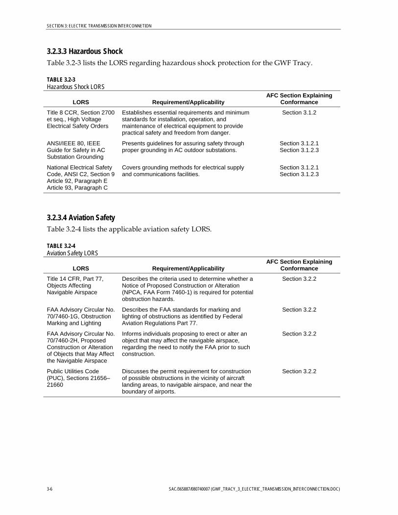
3.2.3.3 Hazardous Shock Table 3.2-3 lists the LORS regarding hazardous shock protection for the GWF Tracy.
TABLE 3.2-3 Hazardous Shock LORS
LORS Requirement/Applicability AFC Section Explaining
Conformance
Title 8 CCR, Section 2700 et seq., High Voltage Electrical Safety Orders
Establishes essential requirements and minimum standards for installation, operation, and maintenance of electrical equipment to provide practical safety and freedom from danger.
Section 3.1.2
ANSI/IEEE 80, IEEE Guide for Safety in AC Substation Grounding
Presents guidelines for assuring safety through proper grounding in AC outdoor substations.
Section 3.1.2.1 Section 3.1.2.3
National Electrical Safety Code, ANSI C2, Section 9 Article 92, Paragraph E Article 93, Paragraph C
Covers grounding methods for electrical supply and communications facilities.
Section 3.1.2.1 Section 3.1.2.3
3.2.3.4 Aviation Safety Table 3.2-4 lists the applicable aviation safety LORS.
TABLE 3.2-4 Aviation Safety LORS
LORS Requirement/Applicability AFC Section Explaining
Conformance
Title 14 CFR, Part 77, Objects Affecting Navigable Airspace
Describes the criteria used to determine whether a Notice of Proposed Construction or Alteration (NPCA, FAA Form 7460-1) is required for potential obstruction hazards.
Section 3.2.2
FAA Advisory Circular No. 70/7460-1G, Obstruction Marking and Lighting
Describes the FAA standards for marking and lighting of obstructions as identified by Federal Aviation Regulations Part 77.
Section 3.2.2
FAA Advisory Circular No. 70/7460-2H, Proposed Construction or Alteration of Objects that May Affect the Navigable Airspace
Informs individuals proposing to erect or alter an object that may affect the navigable airspace, regarding the need to notify the FAA prior to such construction.
Section 3.2.2
Public Utilities Code (PUC), Sections 21656–21660
Discusses the permit requirement for construction of possible obstructions in the vicinity of aircraft landing areas, to navigable airspace, and near the boundary of airports.
Section 3.2.2
3-6 SAC/365887/080740007 (GWF_TRACY_3_ELECTRIC_TRANSMISSION_INTERCONNECTION.DOC)
SECTION 3: ELECTRIC TRANSMISSION INTERCONNETION
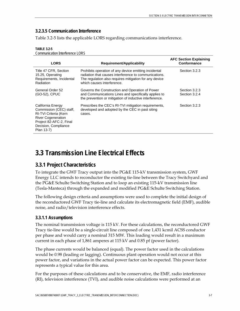
3.2.3.5 Communication Interference Table 3.2-5 lists the applicable LORS regarding communications interference.
TABLE 3.2-5 Communication Interference LORS
LORS Requirement/Applicability AFC Section Explaining
Conformance
Title 47 CFR, Section 15.25, Operating Requirements, Incidental Radiation
Prohibits operation of any device emitting incidental radiation that causes interference to communications. The regulation also requires mitigation for any device which causes interference.
Section 3.2.3
General Order 52 (GO-52), CPUC
Governs the Construction and Operation of Power and Communications Lines and specifically applies to the prevention or mitigation of inductive interference.
Section 3.2.3 Section 3.2.4
California Energy Commission (CEC) staff, RI-TVI Criteria (Kern River Cogeneration Project 82-AFC-2, Final Decision, Compliance Plan 13-7)
Prescribes the CEC’s RI-TVI mitigation requirements, developed and adopted by the CEC in past siting cases.
Section 3.2.3
3.3 Transmission Line Electrical Effects 3.3.1 Project Characteristics To integrate the GWF Tracy output into the PG&E 115-kV transmission system, GWF Energy LLC intends to reconductor the existing tie-line between the Tracy Switchyard and the PG&E Schulte Switching Station and to loop an existing 115-kV transmission line (Tesla-Manteca) through the expanded and modified PG&E Schulte Switching Station.
The following design criteria and assumptions were used to complete the initial design of the reconductored GWF Tracy tie-line and calculate its electromagnetic field (EMF), audible noise, and radio/television interference effects.
3.3.1.1 Assumptions The nominal transmission voltage is 115 kV. For these calculations, the reconductored GWF Tracy tie-line would be a single-circuit line composed of one 1,431 kcmil ACSS conductor per phase and would carry a nominal 315 MW. This loading would result in a maximum current in each phase of 1,861 amperes at 115 kV and 0.85 pf (power factor).
The phase currents would be balanced (equal). The power factor used in the calculations would be 0.98 (leading or lagging). Continuous plant operation would not occur at this power factor, and variations in the actual power factor can be expected. This power factor represents a typical value for this area.
For the purposes of these calculations and to be conservative, the EMF, radio interference (RI), television interference (TVI), and audible noise calculations were performed at an
SAC/365887/080740007 (GWF_TRACY_3_ELECTRIC_TRANSMISSION_INTERCONNECTION.DOC) 3-7
SECTION 3: ELECTRIC TRANSMISSION INTERCONNETION
assumed minimum conductor height above ground of 26 feet (mid-span). However, from a design perspective, the conductors would be a minimum of 30 feet above the ground (34 feet above railroad tracks).
The calculations were performed using the Bonneville Power Administration’s (BPA) Corona and Field Effects Program.
3.3.1.2 Conductor Analysis The selection of a phase conductor size and type for a new transmission line typically considers a number of factors that include the following:
• Thermal Capacity. The conductor size/type selected must have a thermal capacity greater than the future capacity requirements of the project.
• Economics. Economic evaluations typically consider the effects on conductor, structure, and foundation costs of various conductor sizes/types and bundle configurations (conductor diameters, sags, and tensions). The present worth of conductor losses is also typically considered.
• Environmental. Electric and magnetic field strengths are largely dependent on the maximum line operating voltage, phase conductor currents, and the spatial arrangement (configuration) of the phase conductors, not the conductor size/type.
• Standardization. Industry standard/typical conductor sizes/types and bundle configurations are given preference because of operation and maintenance, and in-service reliability considerations.
• Minimum Size. A minimum allowable conductor size of 477 kcmil was selected for this project. This size selection was based on the assumed existing conductor used on the Tesla-Manteca 115-kV transmission line.
3.3.2 Aviation Safety There is no major commercial aviation center in the general vicinity of the project. The Stockton airport is over 20 miles northeast of the GWF Tracy area. A smaller local airport in Tracy, the Tracy Municipal Airport, is within 2 miles of the project transmission line.
In accordance with Title 14, Part 77 of the Code of Federal Regulations (CFR), a Notice of Construction or Alteration must be filed with the Federal Aviation Administration (FAA) if there is any structure rising 200 feet (500 feet in uncongested areas) above the average ground level in the vicinity of the construction site. A notice is also required if any structure protrudes above an imaginary surface extending from the end of the nearest runway at a slope of 50:1 for 10,000 feet, if the longest runway length at the airport is 3,200 feet or less; or a slope of 100:1 for 20,000 feet, if the longest runway at the airport is longer than 3,200 feet.
The closest runway is less than 2 miles away, but the transmission line would not cut the extended imaginary surface of the airport runway. Therefore, an FAA Notice of Construction is not required for the transmission line.
3-8 SAC/365887/080740007 (GWF_TRACY_3_ELECTRIC_TRANSMISSION_INTERCONNECTION.DOC)

SECTION 3: ELECTRIC TRANSMISSION INTERCONNETION
Local crop dusting occurs in the project area. The Tesla-Manteca loop-through would be located within the existing transmission corridors and would not introduce a significant obstacle for crop-dusting activities.
3.3.3 Audible Noise and Radio/TV Interference Audible noise is defined as any unwanted sound from a man-made source such as a transmission line, a transformer, an airport, vehicular traffic, etc. Audible noise is superimposed on the background or ambient noise that existed prior to the introduction of the audible noise source.
When an electric transmission line is energized, an electric field is generated in the air around the conductors. This electric field may cause corona (the breakdown of the air in the vicinity of the transmission line phase conductors). When the intensity of the electric field at the conductor surface exceeds the breakdown strength of the surrounding air, a corona discharge occurs at the conductor surface. This corona discharge produces energy, which can result in audible noise and/or radio and television interference. The corona effects from the line were calculated using the BPA CFE Program.
Corona-generated audible noise can be characterized as a hissing, crackling sound, which, under certain conditions, can be heard. The noise levels generated by the line are very low, and most of the time the audible noise would not be detectable, except in an area directly beneath the line on a quiet day. The audible noise calculation results for the reconductored GWF Tracy tie-line are shown on Figure 3.1-3.
Corona on transmission line conductors can also generate electromagnetic noise in the frequency bands used for radio and television signals. This phenomenon is generally referred to as RI and TVI. These terms are commonly applied to any disturbance within the radio frequency band. RI and TVI consist of two distinct types: gap-type noise and noise due to corona. Gap-type noise is the result of sparking or arcing between two pieces of hardware. This arcing occurs when hardware is loose (not tight-fitting), or at sharp burrs or edges on the hardware. This type of noise occurs at discrete points along the line and is often associated with undermaintained lines. Such interference can be easily identified and corrected with proper maintenance. The second type of noise is caused by corona on the conductors. This corona noise emanates from the entire length of conductor and is typically referred to as RI and TVI.
Corona-related interference with radio and television reception is typically associated with transmission line voltages of 345 kV or greater, although it may occur at lower voltages. It is a direct function of the strength of the received radio/television signal and the level of the noise present. The signal to noise ratio (S/N) is defined as the ratio of the average signal power to the average noise power. The higher the S/N ratio, the better the reception quality. A high S/N ratio indicates a high signal level and a low noise level. Consider the analogy of a person talking in a room with low background noise and a person talking in a room with high background noise. If the person’s voice (signal level) remains constant, the person would be heard much more easily in a room with low background noise than the person in a room with high background noise. This concept also applies to radio and television signals in the presence of background noise.
SAC/365887/080740007 (GWF_TRACY_3_ELECTRIC_TRANSMISSION_INTERCONNECTION.DOC) 3-9
SECTION 3: ELECTRIC TRANSMISSION INTERCONNETION
It is difficult to determine whether a particular level of RI or TVI would cause unacceptable radio or television reception. Studies have been conducted, however, to determine acceptable signal to noise ratios. For radio reception, a S/N ratio above 20 is generally considered to provide acceptable reception. For television reception, an S/N ratio of 30 to 40 typically provides acceptable reception. It is anticipated that for receivers proximate to the reconductored GWF Tracy tie-line, there would be little, if any, degradation of radio or television reception. The exception, if there is one, would be for very remote, poorly received stations. In addition, RI typically interferes with amplitude modulated (AM) stations only. Frequency modulated (FM) stations are generally immune to RI because of the inherent characteristics of the modulation scheme. Therefore, the probability for RI complaints is reduced, because a major band of the radio broadcast spectrum is generally unaffected by the phenomenon. The calculated RI and TVI for the reconductored GWF Tracy tie-line are shown on Figures 3.1-4 and 3.1-5, respectively. These levels of interference are not expected to be noticeable, except for remote stations. The TVI at the edge of the right-of-way would be noticeable only for weak (remote) stations.
The reconductored GWF Tracy tie-line would be maintained as part of a regular maintenance program. Therefore, it is unlikely any gap-type noise would result. If any is reported or discovered, it would be quickly mitigated. In addition, it is anticipated that few if any RI/TVI complaints would occur, because of the low magnitude of calculated corona noise. If complaints do occur, they would be addressed, investigated, and mitigated if needed, on a case-by-case basis.
3.3.4 Electric and Magnetic Fields Electricity is a phenomenon resulting from the existence and interaction of charges. When a charge is stationary or static, it produces forces on objects in regions where it is present. When a charge is in motion, it produces magnetic effects. Whenever electricity is used or transmitted, electric and magnetic fields are created. Transmission lines, distribution lines, house wiring, and appliances produce electric fields in their vicinity due to the electric charges associated with the appliances/conductors. Electric field strengths are typically expressed in units of volts per meter or kilovolts (thousands of volts) per meter (kV/m).
Electric charges in motion (currents) produce magnetic fields. The strength of a magnetic field is proportional to the current through the conductor (circuit) producing the field. Magnetic fields can be characterized by the force they exert on a moving charge or on an electric current. Electric currents are sources of magnetic fields. Magnetic field strengths are measured in milligauss (mG).
An example of electric and magnetic fields in a home is a lamp plugged into an electrical outlet. If the lamp is turned off, an electric field exists in the vicinity of the cord of the lamp because of the voltage on the cord. When the lamp is turned on, current flows through the cord and a magnetic field also exists around the cord because of the current flow.
The strength of an electric field depends on the potential (voltage) of the source of the field, and distance from that source to the point of measurement of the field strength. Electric fields decrease rapidly as the distance (r) from the source increases. If an energized conductor (source) is placed inside a grounded conducting enclosure, the electric field
3-10 SAC/365887/080740007 (GWF_TRACY_3_ELECTRIC_TRANSMISSION_INTERCONNECTION.DOC)

SECTION 3: ELECTRIC TRANSMISSION INTERCONNETION
outside the enclosure would approach zero (limited by ambient electric field level), and the source is said to be shielded.
Transmission-line-related magnetic fields decrease at a rate of 1/r2 if currents are balanced and conductors are closely spaced. Magnetic fields associated with unbalanced phase currents decrease at a rate inversely proportional to the distance from the source (conductor), at a rate of 1/r. Transmission lines typically are operated with balanced phase currents.
The electric field created by a high-voltage transmission line extends from the energized conductors to other nearby conducting objects such as the ground, structures, vegetation, buildings, vehicles, and people. The strength of the vertical component of the electric field at a height of 1 meter (3.28 feet) is frequently used to characterize electric fields under transmission lines.
The transmission line parameters that have the greatest effect on electric and magnetic field levels in the vicinity of a transmission line are maximum operating voltage, line current, conductor height, and electrical phasing. The maximum ground-level electric and magnetic fields typically occur near the centerline of a line and at mid-span where the conductors are closest to the ground. For purposes of these estimates, the minimum mid-span conductor height is assumed to be 26 feet.
The electric and magnetic fields from the reconductored GWF Tracy tie-line were calculated using the BPA Corona and Field Effects Program. The strengths of the electric and magnetic fields were calculated for a sensor height of 1 meter above ground. Calculations were performed based on the minimum 26-foot ground clearance and extend to at least 120 feet on each side of the centerline. The calculated magnetic fields produced by the reconductored GWF Tracy tie-line operating at peak loading conditions are shown on Figure 3.1-6. The magnetic field levels are directly proportional to the current flowing through the transmission line. When current flow is increased or reduced, the magnetic field level also increases or decreases.
The electric field levels produced by the reconductored GWF Tracy tie-line are shown on Figure 3.1-6.
The tie-line is on GWF or PG&E property for its entire length; therefore, there should be little or no change in EMF levels to the general public.
Given the concerns about human exposure to electric and magnetic fields and possible adverse health affects, several states have adopted standards limiting electric and magnetic field levels within or at the edge of transmission line rights-of-way (see Table 3.3-1). California is not one of these states. However, while California does not have regulatory requirements for transmission line magnetic fields, the calculated magnetic fields for the Tesla reconductored GWF Tracy tie-line (refer to Figure 3.3-1) are much lower than the requirements for those states with existing limitations.
California does not regulate the level of transmission line electric fields. However, calculated values for the reconductored GWF Tracy tie-line (refer to Figure 3.1-6) are also substantially below the levels established by those states that do have limits.
SAC/365887/080740007 (GWF_TRACY_3_ELECTRIC_TRANSMISSION_INTERCONNECTION.DOC) 3-11

SECTION 3: ELECTRIC TRANSMISSION INTERCONNETION
3.3.4.1 Transmission Line Electromagnetic Field Reduction Although the State of California does not limit electric and magnetic field levels, the CPUC mandates EMF reduction as a practicable design criterion for new and upgraded electrical facilities. From this mandate, the regulated electric utilities, including PG&E, have developed their own design guidelines to reduce EMF at each new facility. The CEC requires independent power producers to follow the guidelines that have already been established by the local electric utility or transmission-system owner.
TABLE 3.3-1 State Regulatory Requirements on Electric and Magnetic Fields
Electric Field Magnetic ROW
On ROW Edge of ROW Edge of ROW
Florida 8 kV/ma 2 kV/m 150 mGa (max load)
10 kV/mb — 200 mGb (max load)
— — 250 mGc (max load)
Minnesota 8 kV/m — —
Montana 7 kV/md 1 kV/m
New Jersey — 3 kV/m —
New York 11.8 kV/m 1.6 kV/m 200 mG (max load)
11.0 kV/me —
7 kV/md —
North Dakota 9 kV/mf — —
Oregon 9 kV/mg — —
Rhode Island 8 kV/mh — — a For lines of 69 kV–230 kV bFor 500-kV lines cFor double-circuit, 500-kV lines dMaximum for highway crossings eMaximum for private road crossings fFor 230-kV lines and above gFor 230-kV lines and above hFor all new lines ROW=right-of-way
In keeping with the goal of EMF reduction, the GWF Tracy interconnection would be generally designed and constructed using the principles outlined in the PG&E publication, Transmission Line EMF Guidelines. These guidelines incorporate the directives of the CPUC by developing design procedures that comply with Decision 93-11-013 and GO-95, 128, and 131-D. In other words, when the towers, conductors, and rights-of-way are designed and routed according to the PG&E guidelines, the transmission line is consistent with the CPUC mandate.
3-12 SAC/365887/080740007 (GWF_TRACY_3_ELECTRIC_TRANSMISSION_INTERCONNECTION.DOC)

SECTION 3: ELECTRIC TRANSMISSION INTERCONNETION
From the PG&E guidelines, the primary techniques for reducing EMF anywhere along the line are the following:
• Increase the distance from the line conductors • Reduce the spacing between the line conductors • Minimize the current on the line • Optimize the configuration of the phases (A, B, C)
To increase the distance from the line conductors, the line would be routed along an existing utility corridor, thereby avoiding proximity to residential and public-use areas. The nearest residence is approximately 350 feet away. Additionally, along the route of the overhead line, the adjacent land is a mix of industrial, agricultural, and vacant land.
Reducing the spacing between the conductors can reduce magnetic fields. Also, for the double-circuit case, the circuits on one side would be reverse-phased from the circuits on the other side to further reduce resulting magnetic fields.
While the EMF levels have been calculated for the GWF Tracy tie-line as designed, the CEC requires actual measurement of EMF for comparison of “before” (background) with “after” (transmission line and background together) EMF levels. These verification measurements would be made consistent with IEEE guidelines and would provide sampled readings of edge of right-of-way EMF. Additional measurements would be made upon request for areas of particular concern.
3.3.4.2 Conclusion on Electromagnetic Fields Electromagnetic field reduction would be an integral consideration during the design and routing of the interconnection between the GWF Tracy and the offsite transmission lines. Because the PG&E Transmission Line EMF Guidelines embody the CPUC directives for EMF reduction, the guidelines are the primary criteria for EMF considerations in this project.
3.3.5 Induced Current and Voltages A conducting object, such as a vehicle or person, in an electric field would experience induced voltages and currents. The magnitude of the induced current would depend on the electric field strength, the size and shape of the object, and object-to-ground resistance. The measured induced current for a person in a 1-kV/m electric field is 0.016 milliamps (mA); for a large school bus, 0.41 mA; and for a large trailer truck, 0.63 mA.
When a conducting object in an electric field is isolated from ground, and a grounded person touches the object, a perceptible current or shock may occur. The magnitude of the current depends on the field strength, the size (or length for fences, pipelines, and railroad tracks) of the object, and the grounding resistance of the object and person. Shocks are classified as below perception, above perception, secondary, and primary. The mean perception level is 1.0 mA for a 180-pound man and 0.7 mA for a 120-pound woman. Secondary shocks cause no direct physiological harm but may annoy a person and cause involuntary muscle contraction. The lower average secondary-shock level for an average-sized man is about 2 mA. Primary shocks can be harmful; their lower level is described as the current at which 99.5 percent of subjects can still voluntarily “let go” of the shocking
SAC/365887/080740007 (GWF_TRACY_3_ELECTRIC_TRANSMISSION_INTERCONNECTION.DOC) 3-13

SECTION 3: ELECTRIC TRANSMISSION INTERCONNETION
electrode. For the 180-pound man this is 9 mA, for the 120-pound woman, 6 mA, and for children, 5 mA.
The National Electric Safety Code specifies 5 mA as the maximum allowable short-circuit current to ground from vehicles, trucks, and equipment near transmission lines.
The mitigation for hazardous and nuisance shocks is to ensure that metallic objects on or near the right-of-way are grounded, and that sufficient clearances are provided at roadways and parking lots to keep electric-field-induced voltages at these locations sufficiently low to prevent vehicle short-circuit currents resulting from vehicle contact by persons below 5 mA.
Magnetic fields can also induce voltages and currents in conducting objects. Typically, this requires a long metallic object such as a fence, pipeline, or railroad that is grounded at only one location. A person who touches the object, at a location remote from the grounded point, would experience a shock similar to that described above for an ungrounded object. Installing multiple grounds on fences or pipelines parallel to the transmission line can mitigate this problem.
The proposed 115-kV Tesla-Manteca loop-through and the GWF Tracy tie-line would be constructed in conformance with GO-95 and Title 8 CCR, Section 2700 requirements. Therefore, hazardous shocks are unlikely to occur as a result of the GWF Tracy construction or operation.
3.3.6 Nuisance Shocks Normal grounding practices effectively mitigate the possibility of nuisance shocks resulting from induced currents from stationary objects near the line, such as fences and buildings. Since the electric field extends beyond the right-of-way, grounding requirements extend beyond the right-of-way for very large metal objects or very long fences. Electric fences require a special grounding technique because they can operate only if they are insulated. Application of the grounding policy during and after construction would effectively mitigate the potential for shocks from stationary objects near the Tesla-Manteca line and the GWF Tracy tie-line.
3.3.7 Fire Hazards The transmission line and switchyards would be modified and expanded in conformance with CPUC GO-95 and National Electric Safety Code standards. Title 14 CCR, Section 1250, Article 4 (from CPUC GO-95) establishes fire prevention standards for electric utilities. The GWF Tracy would comply with these standards.
3.3.8 Cumulative Effects The Tesla-Manteca transmission line would operate proximate to existing transmission lines along the right-of-way. Interaction with the electric and magnetic fields of other existing lines would depend on the phase arrangements and relative positions of the conductors of the new line compared to the existing lines. An evaluation of these interactions would require detailed construction data on the existing transmission lines that are not currently available. Corona noise for the Tesla-Manteca line is projected to be small and is not expected to significantly increase the ambient noise near the existing lines.
3-14 SAC/365887/080740007 (GWF_TRACY_3_ELECTRIC_TRANSMISSION_INTERCONNECTION.DOC)

SECTION 3: ELECTRIC TRANSMISSION INTERCONNETION
3.4 Transmission System Evaluation 3.4.1 Description of Transmission Alternatives Interconnection alternatives for integrating the nominal 315-MW plant output into the California transmission system grid were evaluated in the original permitting process; therefore, no additional alternatives are presented.
3.4.2 Applicant’s Interconnection Study A load flow and transient system impact analysis has been performed for the permitting of the original TPP. In addition, PG&E completed a fault current study for the original TPP. No significant impacts were identified that would require additional facilities or other mitigation measures.
3.4.3 PG&E System Impact/Facility Study GWF Energy LLC requested that PG&E/California Independent System Operator prepare a System Impact Study for the electrical interconnection of the proposed GWF Tracy. The study, which was completed on May 19, 2008, evaluated the potential impacts of adding an additional 145 MW of generation to the PG&E system (see Appendix 3A).
3.5 Jurisdiction Table 3.5-1 identifies agencies with jurisdiction to issue permits and approvals, and/or enforce laws and regulations.
TABLE 3.5-1 Jurisdiction
Agency or Jurisdiction Responsibility
California Energy Commission Project Manager 1516 9th Street, MS-15 Sacramento, CA 95814-5512
Jurisdiction over new transmission lines associated with thermal power plants that are 50 megawatts or more (Public Resources Code [PRC] 25500); jurisdiction of lines out of a thermal power plant to the interconnection point to the utility grid (PRC 25107); jurisdiction over modifications of existing facilities that increase peak operating voltage or peak kilowatt capacity by 25 percent (PRC 25123).
California Public Utilities Commission Mr. Julian Ajello Supervisor, North California Safety Section 505 Van Ness Avenue San Francisco, CA 94102 (415) 703-1327
Regulates construction and operation of overhead transmission lines (General Order No. 95); regulates construction and operation of underground transmission and distribution lines (General Order No. 128); regulates construction and operation of power and communications lines for the prevention of inductive interference (General Order No. 52).
San Joaquin County Electrical Inspector Department of Public Works Sacramento, CA
Jurisdiction over safety inspection of electrical installations that connect to the supply of electricity (NFPA 70).
Western Systems Coordinating Council Mr. Dennis E. Eyre Executive Director 615 Arapeen Drive, Suite 210 Salt Lake City, UT 84108 (801) 582-0353
Establishes power supply design criteria to improve reliability of the power system.
SAC/365887/080740007 (GWF_TRACY_3_ELECTRIC_TRANSMISSION_INTERCONNECTION.DOC) 3-15

SECTION 3: ELECTRIC TRANSMISSION INTERCONNETION
3-16 SAC/365887/080740007 (GWF_TRACY_3_ELECTRIC_TRANSMISSION_INTERCONNECTION.DOC)
3.6 Agency Contacts Local contacts for the GWF Tracy transmission line and the switchyard are shown in Table 3.6-1.
TABLE 3.6-1 Agency and Utility Contacts
Agency Contact/Title Telephone Number
California Independent System Operator Armando Perez Director, Grid Planning
(916) 331-4444
Pacific Gas & Electric Company Crispin M. Sullivan Project Manager
(415) 257-3317

Figure source: Black & Veatch Corp., 2008
FIGURE 3.1-1INTERCONNECTION TO PG&E TRANSMISSION LINEGWF TRACY COMBINED CYCLE POWER PLANT PROJECT SAN JOAQUIN COUNTY, CA
EY012008001BAO Figure_3_1_1_PGE_interconnect.ai 06-26-08 dash

Figure source: Hanby Young, 2002
FIGURE 3.1-2TRANSMISSION POLE STRUCTUREGWF TRACY COMBINED CYCLE POWER PLANT PROJECT SAN JOAQUIN COUNTY, CA
EY012008001BAO Figure_3_1_2_trans_pole_structure.ai 06-26-08 dash

0
2
4
6
8
10
12
-200 -175 -150 -125 -100 -75 -50 -25 0 25 50 75 100 125 150 175 200 225 250 275 300
Lateral Distance
Aud
ible
Noi
se (D
BA
) Rai
n
-25
-20
-15
-10
-5
0
Aud
ible
Noi
se (D
BA
) Fai
r
Rain L50 Fair L50
FIGURE 3.1-3
Corona-generated Audible Noise Levels at Lateral Distance from Centerline of Reconductored 115-kV Tie-line
0
5
10
15
20
25
30
35
-200 -175 -150 -125 -100 -75 -50 -25 0 25 50 75 100 125 150 175 200 225 250 275 300
Lateral Distance
Rad
io In
terf
eren
ce (D
BuV
/M) R
ain
-20
-15
-10
-5
0
5
10
15
Rad
io In
terf
eren
ce (D
BuV
/M) F
air
Rain L50 Fair L50
FIGURE 3.1-4
Radio Interference Levels at Lateral Distance from Centerline of Reconductored 115-kV Tie-line

-200 -175 -150 -125 -100 -75 -50 -25 0 25 50 75 100 125 150 175 200 225 250 275 300
Lateral Distance
TV In
terf
eren
ce (D
BuV
\M)
-35
-30
-25
-20
-15
-10
-5
0
5
FIGURE 3.1-5
TV Interference Levels at Lateral Distance from Centerline of Reconductored 115-kV Tie-line
0
0.1
0.2
0.3
0.4
0.5
0.6
0.7
0.8
-200 -175 -150 -125 -100 -75 -50 -25 0 25 50 75 100 125 150 175 200 225 250 275 300
Lateral Distance
Elec
tric
kV/
M
0
20
40
60
80
100
120
Mag
netic
(mG
)
Electric Magnetic
FIGURE 3.1-6 FIGURE 3.1-6
Electric and Magnetic Field Levels at Lateral Distance from Centerline of Reconductored 115-kV Tie-line Electric and Magnetic Field Levels at Lateral Distance from Centerline of Reconductored 115-kV Tie-line